deleterious thermal effects due to randomized … · deleterious thermal effects due to randomized...
TRANSCRIPT

Deleterious Thermal Effects due to
Randomized Flow PathsIn
Pebble Bed, and Particle Bed Style Reactors
Robert Moran, Thermal [email protected]‐544‐4005Jan 8 2013 1
https://ntrs.nasa.gov/search.jsp?R=20130011256 2018-09-06T19:54:05+00:00Z

Nuclear Thermal Rocket IntroductionFew rocket propulsion concepts offer the combination of high thrust and reasonable efficiency that can be obtained
from a Nuclear Thermal Rocket (NTR). Long considered one of the most basic forms of Nuclear Propulsion, the solid‐core nuclear thermal rocket engine concept typically employs a uranium fueled nuclear reactor core and hydrogen (H2) gas working fluid. The H2 gas acts first as fuel rod coolant as it passes through the nuclear reactor core followed by rocket working fluid when the then super heated hydrogen is expanded out of a nozzle in order to produce thrust.
2
Famously the Nuclear Engine for Rocket Vehicle Application, or NERVA test program of the 1960’s extensively demonstrated the feasibility of the nuclear thermal rocket design concept, testing nearly 30 nuclear thermal rocket engines suchat the KIWI‐B4 which produced approximately 75,000 pounds of thrust with an efficiency (isp) of 825 seconds.
A typical Nuclear Thermal Propulsion (NTP) rocket engine is the product of a host of design tradeoffs including but not limited to heat transfer, structural including fuel thermal swelling, core reactivity, radiation shielding, thrust, volume, mass, and etc
Fuel surface area plays a key role in heat transfer along with the availability of coolant pathways thus the surface to volume ratio of a NTP concept is often used as a quality measure

NERVA/Rover NTP limitations• NERVA/ROVER designs were very large and very heavy• A typical NERVA program Nuclear Thermal Propulsion (NTP) system averaged a thrust to weight ratio of about 4:1• Fails to meet the low mass requirements, and limited available space of today’s space launch vehicles
• Precludes most unmanned missions• Modern chemical liquid oxygen ‐ liquid hydrogen (LOX/LH2) engines routinely achieve 50:1 and higher
• Space Shuttle Main Engine T/W is about 65:1 in vacuum
3

Review of Modern NTP Concepts
4
• Modern NTP designs would like to achieve an efficiency (isp) of 1000 seconds versus NERVA 825 seconds• NTP fuel rods will be exposed to extreme operating temperatures and pressures to achieve an isp of 1000 seconds
• Operating in excess of 5000 °f, and 1000 psi• Next generation designs would like to achieve a superior thrust to weight ratio over NERVA 4 to 1
• Will require non‐traditional fuel rod materials, geometry, and manufacturing techniques
• A literature review of several modern solid core potential NTP concepts was performed• The purpose of the review was to identify both the strong and weak points of each fuel element concept, hoping to glean
the ideal fuel rod characteristics for optimum thermal heat transfer to the coolant/working fluid while still maintaining structural integrity
• A large fuel rod surface area ideally shaped to promote heat transfer to the hydrogen working fluid while simultaneously avoiding structural degradation due to the high operating temperatures and pressures
• Pebble Bed Reactor• Particle Bed Reactor• Foam Core Reactor

Localized Thermal Instability Deleterious thermal effects systemic to Pebble Bed and Particle Bed designs were identified• Both designs suffered from unexplained localized thermal instabilities leading to thermal runaway and fuel melting
Similarities of the two designs• Small localized hot spots can occur within a reactor core for any one of a host of reasons unrelated to coolant flow
• Design flaw• Manufacturing flaw• Fuel migration within the pellet/particles affecting fission reactivity• Small instabilities that are randomly inherent to a large scale fission reaction
• Coolant flow will resist localized high temperature regions• Coolant fluid properties change with temperature
• Both Pebble Bed and Particle Bed reactors by design utilize randomized coolant channel pathways• Traditional designs such as the close packed hexagonal reactor cores have structured coolant flow pathways
• Have a greater thermal stability
5

Pebble bed Reactor• Helium cooled, graphite moderated, high temperature reactor • Use thousands of marble to softball sized ceramic coated uranium fuel pebbles
6
• The encapsulating style of the pebbles can lead to both structural and reactivity issues when built up fission product gasses trapped within the pebble by the outer coating layers force the uranium fuel to migrate away from the center of the pebble
• Pebble Beds have high operating temperatures (1700 ⁰F helium exit temperatures) compared to most nuclear electric plants• Pebbles ceramic encapsulating style significantly reduces the negative effects of fuel melting• The pebbles are stacked in the reactor core like cannon balls resulting in significant volume between them, massively
increasing the total volume requirements of this type of design and limiting it’s applicability to Nuclear Thermal Propulsion• A 5.1x10⁷ BTU/hr (15 MW) electric, helium cooled pebble bed plant was successfully demonstrated in Germany
• Suffered from temperature instabilities which resulted in localized thermal runaway for indeterminate reasons • Subsequent fuel melting heavily contaminated the pressure vessel with Cs‐137 and Sr‐90

Particle Bed Reactor• Hydrogen cooled high temperature reactor • uses billions of 400 micron sized ceramic coated uranium fuel particles held inside a porous walled (Frit) fuel rod
7
• Fuel particles were known to block the porous passages of the frit, inhibiting the flow of hydrogen coolant
• Reactor operation would result in permanent structural deformation (i.e. bowing of the specially manufactured porous material frits due to thermal expansion)
• Has an expected efficiency (isp) of 1000 seconds with accompanying operating temperatures of 5000 ⁰F• Expected thrust to weight ratio of 35 to 1• Testing reveled that marble sized regions spread throughout the fuel rod would suffer from excessive heating,
subsequent thermal runaway, and localized fuel melting for indeterminate reasons• Potentially related to clogging or deformation of the Frit, which would effect reactor criticality

Foam Core Reactor• Fuel Element comprised of Uranium based bi‐carbide, tri‐carbide or carbonitride fuels chemical vapor deposited onto
porous carbon foam
8
• The Foam Fuel element eliminates the need for a porous (frit) container which are known to permanently deformation
• The Foam Fuel element does not have any loose fuel particles which are known to block the porous coolant passages of other designs
• Has an expected efficiency (isp) of 925 seconds with accompanying high operating temperatures• Expected thrust to weight ratio of 35 to 1
Excerpt from the original patent application (15)
Excerpt from the original patent application (15)
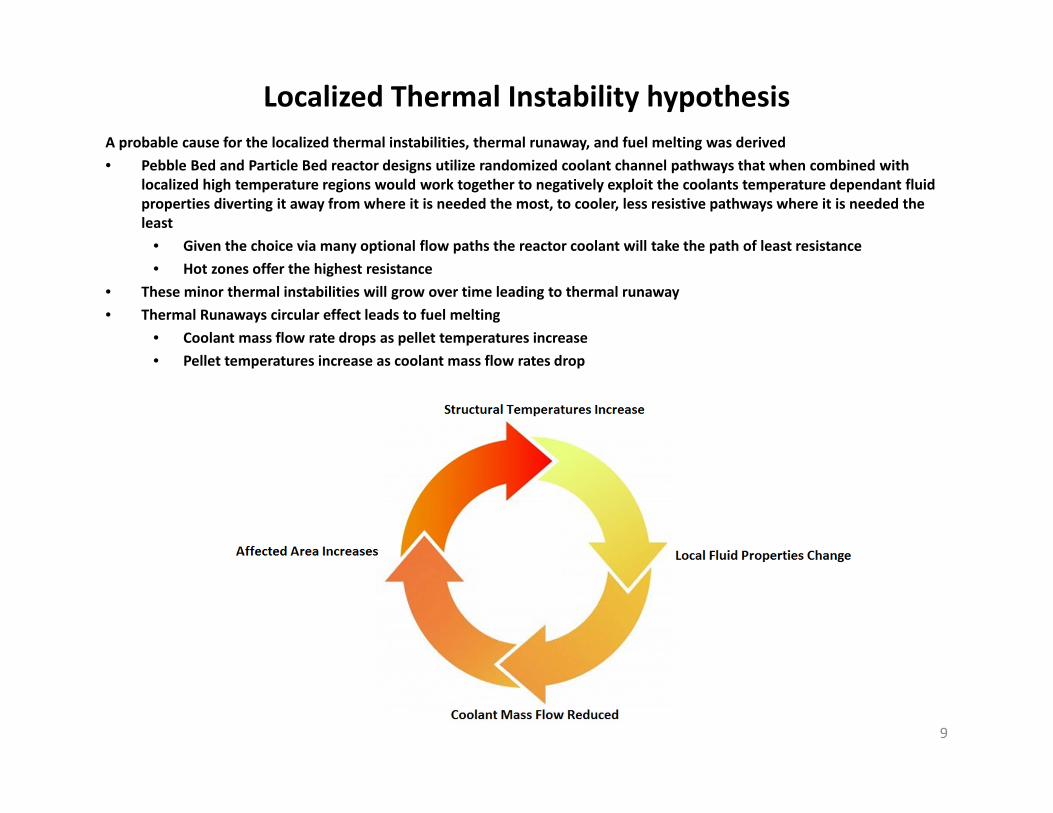
Localized Thermal Instability hypothesis A probable cause for the localized thermal instabilities, thermal runaway, and fuel melting was derived• Pebble Bed and Particle Bed reactor designs utilize randomized coolant channel pathways that when combined with
localized high temperature regions would work together to negatively exploit the coolants temperature dependant fluid properties diverting it away from where it is needed the most, to cooler, less resistive pathways where it is needed the least
• Given the choice via many optional flow paths the reactor coolant will take the path of least resistance• Hot zones offer the highest resistance
• These minor thermal instabilities will grow over time leading to thermal runaway• Thermal Runaways circular effect leads to fuel melting
• Coolant mass flow rate drops as pellet temperatures increase • Pellet temperatures increase as coolant mass flow rates drop
9
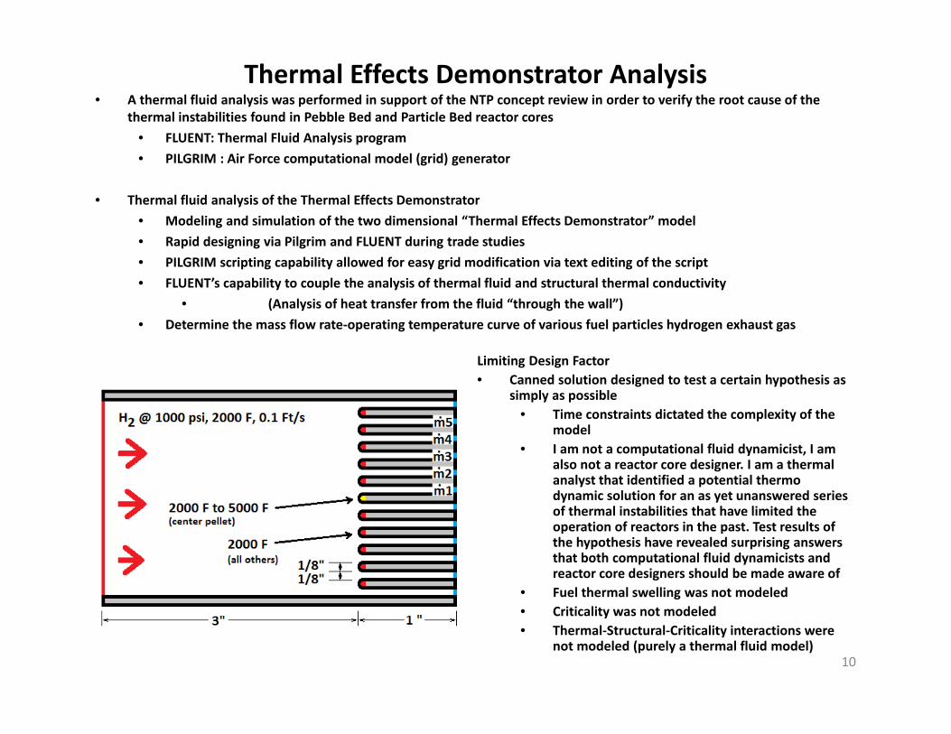
Thermal Effects Demonstrator Analysis• A thermal fluid analysis was performed in support of the NTP concept review in order to verify the root cause of the
thermal instabilities found in Pebble Bed and Particle Bed reactor cores• FLUENT: Thermal Fluid Analysis program• PILGRIM : Air Force computational model (grid) generator
• Thermal fluid analysis of the Thermal Effects Demonstrator• Modeling and simulation of the two dimensional “Thermal Effects Demonstrator” model • Rapid designing via Pilgrim and FLUENT during trade studies• PILGRIM scripting capability allowed for easy grid modification via text editing of the script• FLUENT’s capability to couple the analysis of thermal fluid and structural thermal conductivity
• (Analysis of heat transfer from the fluid “through the wall”)• Determine the mass flow rate‐operating temperature curve of various fuel particles hydrogen exhaust gas
10
Limiting Design Factor• Canned solution designed to test a certain hypothesis as
simply as possible• Time constraints dictated the complexity of the
model• I am not a computational fluid dynamicist, I am
also not a reactor core designer. I am a thermal analyst that identified a potential thermo dynamic solution for an as yet unanswered series of thermal instabilities that have limited the operation of reactors in the past. Test results of the hypothesis have revealed surprising answers that both computational fluid dynamicists and reactor core designers should be made aware of
• Fuel thermal swelling was not modeled• Criticality was not modeled• Thermal‐Structural‐Criticality interactions were
not modeled (purely a thermal fluid model)
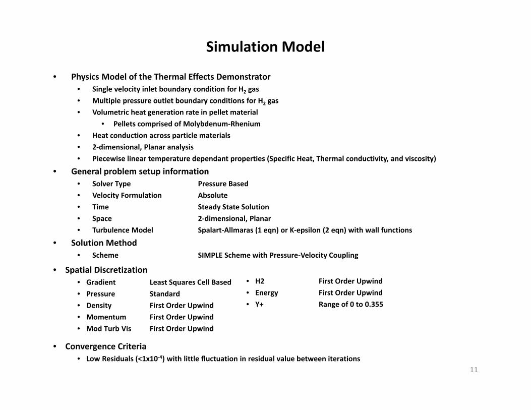
Simulation Model
• Physics Model of the Thermal Effects Demonstrator• Single velocity inlet boundary condition for H2 gas• Multiple pressure outlet boundary conditions for H2 gas• Volumetric heat generation rate in pellet material
• Pellets comprised of Molybdenum‐Rhenium• Heat conduction across particle materials• 2‐dimensional, Planar analysis• Piecewise linear temperature dependant properties (Specific Heat, Thermal conductivity, and viscosity)
• General problem setup information• Solver Type Pressure Based• Velocity Formulation Absolute• Time Steady State Solution• Space 2‐dimensional, Planar• Turbulence Model Spalart‐Allmaras (1 eqn) or K‐epsilon (2 eqn) with wall functions
• Solution Method• Scheme SIMPLE Scheme with Pressure‐Velocity Coupling
11
• Spatial Discretization• Gradient Least Squares Cell Based • Pressure Standard• Density First Order Upwind• Momentum First Order Upwind• Mod Turb Vis First Order Upwind
• H2 First Order Upwind• Energy First Order Upwind• Y+ Range of 0 to 0.355
• Convergence Criteria• Low Residuals (<1x10‐4) with little fluctuation in residual value between iterations
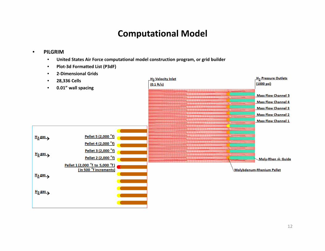
Computational Model
• PILGRIM• United States Air Force computational model construction program, or grid builder• Plot‐3d Formatted List (P3dF)• 2‐Dimensional Grids• 28,336 Cells• 0.01” wall spacing
12
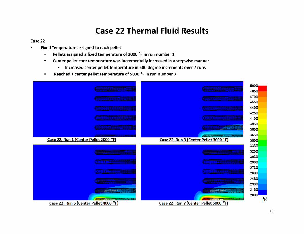
Case 22 Thermal Fluid ResultsCase 22• Fixed Temperature assigned to each pellet
• Pellets assigned a fixed temperature of 2000 ⁰F in run number 1• Center pellet core temperature was incrementally increased in a stepwise manner
• Increased center pellet temperature in 500 degree increments over 7 runs• Reached a center pellet temperature of 5000 ⁰F in run number 7
13

Case 22 Thermal Fluid Results Cont.Case 22• Fixed Temperature assigned to each pellet
• Contour plots show marked increase of coolant velocity in outlier channels as center pellet temperature increases
14

Case 22 Thermal Fluid Results Cont.
15
Case 22• Fixed Temperature assigned to each pellet
• Coolant mass flow rate past the overheating pellet is reduced with increasing temperature
2.5000E‐04
3.0000E‐04
3.5000E‐04
4.0000E‐04
4.5000E‐04
5.0000E‐04
5.5000E‐04
6.0000E‐04
2000 2500 3000 3500 4000 4500 5000
Mass F
low Rate (lb
m/s)
Temperature (F)
Mass Flow Rate vs Temperature
m1
m2
m3
m4
m5

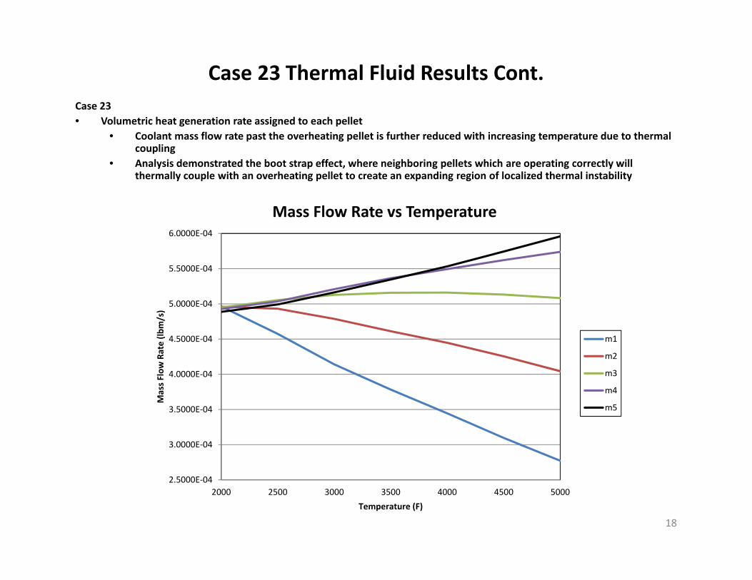
Case 23 Thermal Fluid ResultsCase 23• Volumetric heat generation rate assigned to each pellet
• Pellets reached a temperature of 2000 ⁰F (±10 ⁰F) in run number 1• Heat generation rate was increased in the center pellet to increase pellet core temperature
• Adjusted center pellet temperature in 500 (±10 ⁰F) degree increments over 7 runs• Reached a center pellet temperature of 5000 ⁰F (±10 ⁰F) in run number 7
16

Case 23 Thermal Fluid Results Cont.Case 23• Volumetric heat generation rate assigned to each pellet
• Contour plots show marked increase of coolant velocity in outlier channels as center pellet temperature increases• Increased coupling of coolant velocity profiles between neighboring channels is demonstrated
17
Case 23 Thermal Fluid Results Cont.
18
2.5000E‐04
3.0000E‐04
3.5000E‐04
4.0000E‐04
4.5000E‐04
5.0000E‐04
5.5000E‐04
6.0000E‐04
2000 2500 3000 3500 4000 4500 5000
Mass F
low Rate (lb
m/s)
Temperature (F)
Mass Flow Rate vs Temperature
m1
m2
m3
m4
m5
Case 23• Volumetric heat generation rate assigned to each pellet
• Coolant mass flow rate past the overheating pellet is further reduced with increasing temperature due to thermal coupling
• Analysis demonstrated the boot strap effect, where neighboring pellets which are operating correctly will thermally couple with an overheating pellet to create an expanding region of localized thermal instability
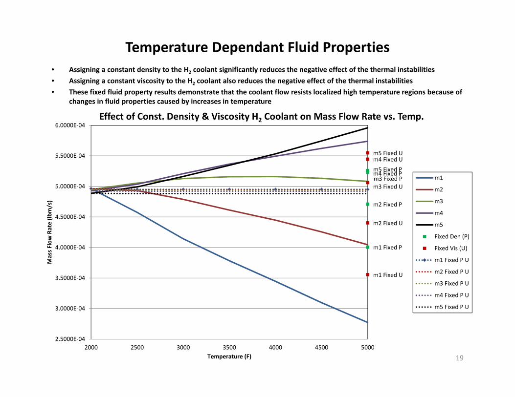
Temperature Dependant Fluid Properties• Assigning a constant density to the H2 coolant significantly reduces the negative effect of the thermal instabilities• Assigning a constant viscosity to the H2 coolant also reduces the negative effect of the thermal instabilities• These fixed fluid property results demonstrate that the coolant flow resists localized high temperature regions because of
changes in fluid properties caused by increases in temperature
19
m1 Fixed P
m2 Fixed P
m3 Fixed Pm3 Fixed U
m4 Fixed Pm5 Fixed P
m1 Fixed U
m2 Fixed U
m4 Fixed Um5 Fixed U
2.5000E‐04
3.0000E‐04
3.5000E‐04
4.0000E‐04
4.5000E‐04
5.0000E‐04
5.5000E‐04
6.0000E‐04
2000 2500 3000 3500 4000 4500 5000
Mass F
low Rate (lb
m/s)
Temperature (F)
Effect of Const. Density & Viscosity H2 Coolant on Mass Flow Rate vs. Temp.
m1
m2
m3
m4
m5
Fixed Den (P)
Fixed Vis (U)
m1 Fixed P U
m2 Fixed P U
m3 Fixed P U
m4 Fixed P U
m5 Fixed P U

Results/ObservationsThe Thermal Effects Demonstrator does not just mimic the symptoms it also shows why randomized flow paths are vulnerable
to minor thermal instabilities• The difference in pressure along the length of the Thermal Effects Demonstrator (∆P > 0) ensures coolant mass flow• There is no pressure difference perpendicular to the length (∆P ≈ 0) of the main channel• When the flow encounters surface area that is perpendicular to the ∆P at the tips of the pellets it stagnates• With no ∆P to drive the stagnated flow the coolant is instead directed by what begins as relatively small thermal effects• These thermal effects then go on to rapidly build up out of control as a pellet is literally starved for coolant
20
Observations• In an effort to overcome the shortcomings of current NTP designs a great deal of emphasis has been placed on the
Surface Area to Volume ratio (S/V) of the next generation concepts• This has lead to several advanced design concepts that would or could utilize randomized flow paths• This analysis has demonstrated that nuclear thermal rocket reactor core designs which utilize randomized flow paths are
highly vulnerable to the types of minor thermal instabilities that lead to thermal runaway• Designs with structured flow paths easily overcome these very same types of thermal instabilities with no impediment• A large Surface Area that is Parallel to the ∆P to Volume ratio (=S/V) positively impacts the design• A large Surface Area that is Perpendicular to the ∆P to Volume ratio (+S/V) negatively impacts the design• Parallel Surface Area plus Perpendicular Surface Area equals Total Surface Area (=S) + (+S) = ST• A large Total Surface Area to Volume ratio (ST/V) is indeterminate in predicting the thermal stability of a given design• A set of cross flow pumps which establish a small ∆P in the perpendicular direction would easily overcome the initial
minor thermal instabilities before they have time to build up • A cross flow ∆P may be difficult to apply to highly randomized flow paths of irregularly shaped pellets such as the Particle
Bed, but should be applicable to Pebble Bed designs
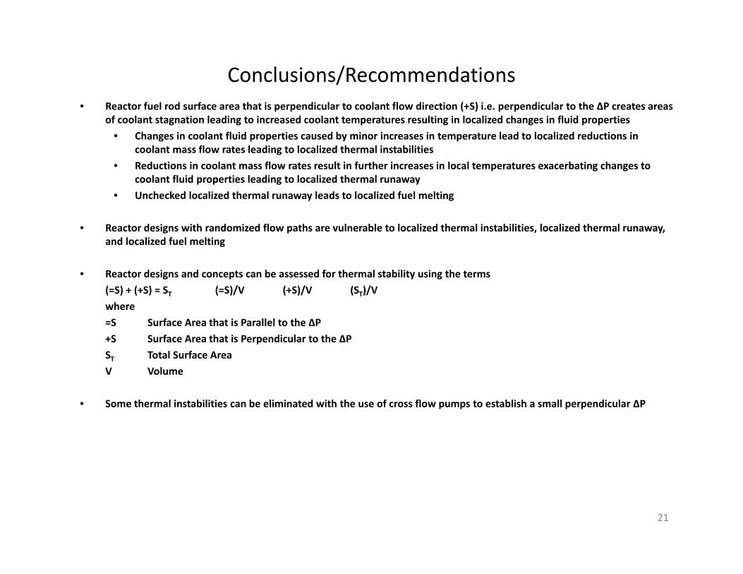
Conclusions/Recommendations• Reactor fuel rod surface area that is perpendicular to coolant flow direction (+S) i.e. perpendicular to the ∆P creates areas
of coolant stagnation leading to increased coolant temperatures resulting in localized changes in fluid properties• Changes in coolant fluid properties caused by minor increases in temperature lead to localized reductions in
coolant mass flow rates leading to localized thermal instabilities• Reductions in coolant mass flow rates result in further increases in local temperatures exacerbating changes to
coolant fluid properties leading to localized thermal runaway• Unchecked localized thermal runaway leads to localized fuel melting
• Reactor designs with randomized flow paths are vulnerable to localized thermal instabilities, localized thermal runaway, and localized fuel melting
• Reactor designs and concepts can be assessed for thermal stability using the terms(=S) + (+S) = ST (=S)/V (+S)/V (ST)/V where=S Surface Area that is Parallel to the ∆P+S Surface Area that is Perpendicular to the ∆PST Total Surface AreaV Volume
• Some thermal instabilities can be eliminated with the use of cross flow pumps to establish a small perpendicular ∆P
21

References• 1. Philip G. Hill and Carl R. Peterson, Mechanics and Thermodynamics of Propulsion, Reading, MA: Addi‐son‐Wesley
Publishing Company, 1965, p. 478. • 2. http://en.wikipedia.org/wiki/Pebble_bed_reactor • 3. http://www.euronuclear.org/info/encyclopedia/p/ • pebble.htm • 4. http://www.eskom.co.za/c/article/71/pebble‐bed‐modular‐reactor/ • 5. http://en.wikipedia.org/wiki/AVR_reactor • 6. http://en.wikipedia.org/wiki/HTR‐10 • 7. http://en.wikipedia.org/wiki/PBMR • 8. AIAA 91‐3404 Fast Mission to Mars with a Particle Bed Reactor Propulsion System • 9. AIAA 92‐3408 Planetary Capture Vehicle Based on a Particle Bed Reactor Propulsion System • 10. IAF 92‐0555 Solar System Exploration Missions Utiliz‐ing a Particle Bed Reactor Propulsion System • 11. Inspector General Audit Report 93‐033, The Tim‐ber Wind Special Access Program • 12. Nuclear Thermal Propulsion for Manned Mission to Mars • 13. Particle Bed Test Program Presentation • 14. A vortex‐Compensated Integrated Cold Frit/Moderator • 15. Porous Nuclear Fuel Element for High Temperature Gas‐Cooled Nuclear Reactors US7899146
22