delamination identification on composite … identification on composite material by free vibration...
TRANSCRIPT

227
Int. J. Mech. Eng. & Rob. Res. 2012 R Sultan et al., 2012
DELAMINATION IDENTIFICATION ONCOMPOSITE MATERIAL BY FREE VIBRATION
TESTR Sultan1*, S Guirguis2, M Younes2 and E El-Soaly3
*Corresponding Author: R Sultan,[email protected]
The composite materials are well known by their excellent combination of high structural stiffnessand low weight. Their inherent anisotropy allows the designer to tailor the material in order toachieve the desired performance requirements. However the delamination which is one of theserious defects often develops and propagates in composite structure. The presence ofdelamination warrants the design life of the structure and the safety. Hence the presence ofsuch defect has to be detected in time to plan the remedial action well in advance. The presentstudy involves extensive experimental works to investigate the free vibration of woven fiber Glass/Epoxy composite laminate plates in simply supported boundary conditions based on the comparisonbetween natural frequencies of the healthy and delaminated composite laminate plates. The squarespecimens of woven glass fiber and epoxy matrix composite were manufactured by the hand-layup technique with different areas of artificial delamination. Elastic parameters of the plate werealso determined experimentally by tensile testing. The present free vibration experiments wereused to validate the results obtained from the FEM numerical analysis. A three-dimensional finiteelement modelling was employed to simulate the dynamic response of composite laminated plateswith and without delamination to extract their natural frequencies. The effect of increasingdelamination area on natural frequencies was studied experimentally and numerically. The naturalfrequencies extracted from the current numerical simulations were compared with experimentalresults. Numerical results showed a good agreement with available experimental data.
Keywords: Laminated composite material, Finite element method, Free vibration test,Delamination
INTRODUCTIONComposite materials are composed of at leasttwo elements working together to produce
ISSN 2278 – 0149 www.ijmerr.comVol. 1, No. 3, October 2012
© 2012 IJMERR. All Rights Reserved
Int. J. Mech. Eng. & Rob. Res. 2012
1 Libyan Air Force, Libya.2 Egyptian Armed Forces, Egypt.3 10th of Ramadan Higher Institute of Technology, Egypt.
material properties that are different to theproperties of those elements on their own.There are of constituent materials: matrix and
Research Paper

228
Int. J. Mech. Eng. & Rob. Res. 2012 R Sultan et al., 2012
reinforcement. The matrix material surroundsand supports the reinforcement materials bymaintaining their relative positions. Thereinforcements impart special physical(mechanical and electrical) properties toenhance the matrix properties. Compositematerials are widely used because of their lessweight to strength ratio. Now composites arealso used in aerospace industry, many jetsand airplanes are made of compositematerials that are stronger and lighter than thematerials they were made from (Jones, 1975;Tsai and Hahn, 1980; Agarwal and Broutman,1990; and Schwartz, 1997). Woven fabricsprovide excellent integrity and conformabilityfor advanced structural composite applications.The reinforcement of composites with wovenfiber materials lead to improved properties ofcomposite structures in terms of acoustical,elastical and thermal properties. Glass fibersare the most commonly used ones in low tomedium performance composites because oftheir high tensile strength and low cost. To betterunderstand any structural vibration problem, thenatural frequencies of a structure need to beidentified. Today due to the advancement incomputer aided data acquisition systems andinstrumentation, experimental modal analysishas become an extremely important tool in thehands of an experimentalist. A number ofresearchers have been developed numeroussolution methods to analysis the dynamicbehaviour of laminated composite laminates.However experimental investigations on wovenfabric composite laminated structures are stilllimited (Itishree and Shishir, 2012).
Several research studies have been carriedfor the composite structures with delamination.They are related to the modelling aspects ofthe composite structures with delamination
(Della and Shu, 2007; Aniello, 2008; Alnefaie,2009; and Kudela and Ostachowicz, 2009).
There are different studies using finiteelement method, Komur et al. (2009)presented a buckling analysis of woven glasspolyester laminated composite plates withcircular and elliptical hole. Alnefaie (2009)developed three dimensional finite elementmodel of delaminated composite plate. Israrand Jyoti (2009) studied the dynamicbehaviour of delaminated composite platebased on numerically simulated experiment.Various examples studied by Hua et al. (2002)in many previous researches to verify thejustification, accuracy and efficiency of the finiteelement model with delamination. Zhang et al.(2010) used commercial finite elementsoftware ANSYS to build finite element modelsfor both undamaged and delaminated carbonfiber reinforced composite beams and platesto study their vibration behaviour.
This work presents an experimental andnumerical study of modal testing of woven fiberGlass/Epoxy laminated composite platescontain different areas of mid plane artificialdelamination. A three-dimensional finiteelement modelling was employed to simulatethe dynamic response of composite laminateplates with delamination to extract their naturalfrequencies. The effect of increasingdelamination area on natural frequencies wasstudied experimentally and numerically.Numerical results show a good agreementwith the available experimental data.
EXPERIMENTAL PROGRAMMEProduction of the LaminatesSpecimens
E glass woven f iber was used asreinforcement in the form of bidirectional
229
Int. J. Mech. Eng. & Rob. Res. 2012 R Sultan et al., 2012
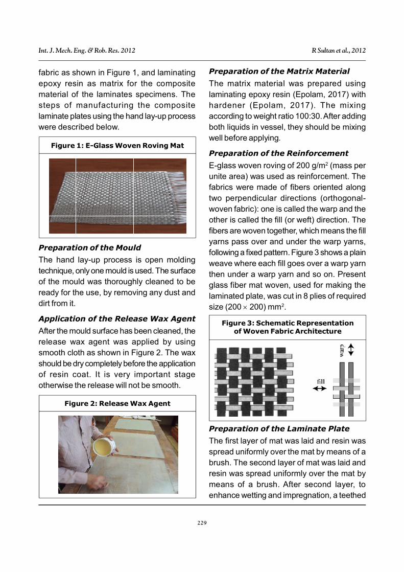
fabric as shown in Figure 1, and laminatingepoxy resin as matrix for the compositematerial of the laminates specimens. Thesteps of manufacturing the compositelaminate plates using the hand lay-up processwere described below.
Preparation of the Matrix Material
The matrix material was prepared usinglaminating epoxy resin (Epolam, 2017) withhardener (Epolam, 2017). The mixingaccording to weight ratio 100:30. After addingboth liquids in vessel, they should be mixingwell before applying.
Preparation of the Reinforcement
E-glass woven roving of 200 g/m2 (mass perunite area) was used as reinforcement. Thefabrics were made of fibers oriented alongtwo perpendicular directions (orthogonal-woven fabric): one is called the warp and theother is called the fill (or weft) direction. Thefibers are woven together, which means the fillyarns pass over and under the warp yarns,following a fixed pattern. Figure 3 shows a plainweave where each fill goes over a warp yarnthen under a warp yarn and so on. Presentglass fiber mat woven, used for making thelaminated plate, was cut in 8 plies of requiredsize (200 200) mm2.
Figure 1: E-Glass Woven Roving Mat
Preparation of the Mould
The hand lay-up process is open moldingtechnique, only one mould is used. The surfaceof the mould was thoroughly cleaned to beready for the use, by removing any dust anddirt from it.
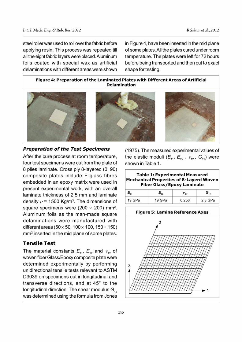
Application of the Release Wax Agent
After the mould surface has been cleaned, therelease wax agent was applied by usingsmooth cloth as shown in Figure 2. The waxshould be dry completely before the applicationof resin coat. It is very important stageotherwise the release will not be smooth.
Figure 2: Release Wax Agent
Figure 3: Schematic Representationof Woven Fabric Architecture
Preparation of the Laminate Plate
The first layer of mat was laid and resin wasspread uniformly over the mat by means of abrush. The second layer of mat was laid andresin was spread uniformly over the mat bymeans of a brush. After second layer, toenhance wetting and impregnation, a teethed
230
Int. J. Mech. Eng. & Rob. Res. 2012 R Sultan et al., 2012
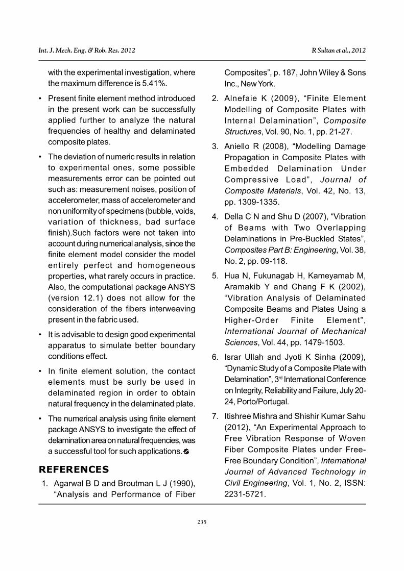
steel roller was used to roll over the fabric beforeapplying resin. This process was repeated tillall the eight fabric layers were placed. Aluminumfoils coated with special wax as artificialdelaminations with different areas were shown
in Figure 4, have been inserted in the mid planeof some plates. All the plates cured under roomtemperature. The plates were left for 72 hoursbefore being transported and then cut to exactshape for testing.
Figure 4: Preparation of the Laminated Plates with Different Areas of ArtificialDelamination
Preparation of the Test Specimens
After the cure process at room temperature,four test specimens were cut from the plate of8 plies laminate. Cross ply 8-layered (0, 90)composite plates include E-glass fibresembedded in an epoxy matrix were used inpresent experimental work, with an overalllaminate thickness of 2.5 mm and laminatedensity = 1500 Kg/m3. The dimensions ofsquare specimens were (200 200) mm2.Aluminum foils as the man-made squaredelaminations were manufactured withdifferent areas (50 50, 100 100, 150 150)mm2 inserted in the mid plane of some plates.
Tensile Test
The material constants E11
, E22
and 12
ofwoven fiber Glass/Epoxy composite plate weredetermined experimentally by performingunidirectional tensile tests relevant to ASTMD3039 on specimens cut in longitudinal andtransverse directions, and at 45° to thelongitudinal direction. The shear modulus G
12
was determined using the formula from Jones
(1975). The measured experimental values ofthe elastic moduli (E
11, E
22 ,
12 , G
12) were
shown in Table 1.
E11
E22
12
G12
19 GPa 19 GPa 0.256 2.8 GPa
Table 1: Experimental MeasuredMechanical Properties of 8-Layerd Woven
Fiber Glass/Epoxy Laminate
Figure 5: Lamina Reference Axes

231
Int. J. Mech. Eng. & Rob. Res. 2012 R Sultan et al., 2012
FINITE ELEMENT MODELUSING ANSYSFinite element analysis for compositematerials is much more complex ascompared to isotropic materials, in terms ofinput and output informations. Special careneeds to be taken for the orientation of pliesand direction of their associated properties.In the present research, the commercial finiteelement software ANSYS was used to buildfinite element models for both healthy anddelaminated cross ply 8-layered (0, 90) platesto study their vibration behaviour. The 3-Dlayered structural solid shell (SOLSH190) is8 nodes element with three degrees offreedom per node was used; this elementtype can be used for simulating structure withwide range of thickness. The element allows250 layers for modelling laminatedcomposite. The layer information is input byusing section commands rather than realconstant.
RESULTS AND DISCUSSIONGenerally, a plate with delamination willexperience reduction in natural frequenciesdue to the loss of stiffness. The extent ofstiffness loss depends on delaminationcharacteristic.
Numerical Results
Numerical results were carried out todetermine the capability of the present FEMto predict natural frequencies of healthy anddelaminated cross ply (0, 90) laminatecomposite plates.
Verification
In order to analyze the vibration response toextract natural frequencies of healthy and
Figure 6: Vibration Test System
Test Procedure for Free VibrationTest
Vibration tests were conducted on plates withsimply support boundary conditions around thefour edges. Through vibration testing, it wasdetermined FRFs (Frequency ResponseFunctions) which relate the response given bythe specimen when impacted by hammer,allowing for the determination of the naturalfrequencies, this was done by fixing thelaminate specimen in special simply supportlocally manufactured apparatus as shown inFigure 6. The impact hammer was used to givethe input load (pulse) to the specimen, thenoutput was captured by the accelerometer andis amplified using a conditioning amplifier andthen read using the high resolution signalanalyzer, giving the FRF. For every specimenmultiple measurements were conducted.

232
Int. J. Mech. Eng. & Rob. Res. 2012 R Sultan et al., 2012
delaminated composite plates, FEM was
proposed in the present work. Previous
published research was employed in this
subsection to verify the justification, accuracy
and efficiency of the present Finite Element
Model. Clamped composite square laminates
(0°/90°/45°/90°) with side length 250 mm,
thickness 2.12 mm, and density = 1446.20
kg/m3, with a square delamination 125 125
mm2 at middle plane of plate was investigated.
The laminate elastic constants are E11
= 1.32
102 GPa; E22
= 5.35 GPa; G12
= 2.79 GPa;
12
= 13
= 0.29; 23
= 0.3. The numerical results
of present FEM in Table 2 showed a good
agreement with the previously published finite
element results (Ju et al., 1995).
First Healthy 344.37 346.59
Delaminated 322.53 334.67
Second Healthy 658.60 651.51
Delaminated 560.18 579.43
Table 2: Comparison of NaturalFrequencies of a Healthy and
Delaminated Clamped Square CompositeLaminate Plate (0°/90°/45°/90°)s
Mode Condition Present FEMJu et al.(1995)
be used to study how midplane delamination
with different areas effects natural frequencies
and comparing the obtained numerical results
with experimental measured results. The
results from present FEM validated with the
experiments conducted on cross eight plies
(0/90) with simply supported boundary
condition accomplished in our laboratory.
Table 3 and Figure7 show the comparison of
frequencies predicted for the first four modes
by using the present finite element model
(ANSYA 12.1) and those measured
experimentally on the healthy and
delaminated woven fiber Glass/Epoxy square
plates. The natural frequencies with increase
of delamination area for both experimental
and numerical results were decreased. From
Figure 7 it arises that the results obtained from
numerical calculations were in good
agreement with the experimental
investigation. The maximum error between
FEM and experimental test results were less
than 5.41%. The present verified finite
element model can be used for further
analysis and the comparison shows that the
introduced FEM is capable of providing
accurate predictions for natural frequencies
of healthy and delaminated laminate
composite plates.
Healthy 172.2 179.40 459.5 466.95 466.3 466.95 686.4 697.47
50 50 170.3 178.82 420.8 413.85 432.5 424.57 637.3 648.62
100 100 169.2 174.86 314.5 326.02 337.4 329.47 549.2 547.26
150 150 159.4 156.30 258.8 267.13 271.2 267.31 293.3 277.43
Table 3: Comparison Between Experimental Measured Natural Frequenciesand Present Finite Element Results of Simply Supported Square Laminate Plates
Delaminationarea mm2
First Mode Second Mode Third Mode Fourth Mode
EX FE EX FE EX FE EX FE
Modal Analysis
After validating the present finite elementmodel with the existing literature, FEM can

233
Int. J. Mech. Eng. & Rob. Res. 2012 R Sultan et al., 2012
Figure 7: Comparison of Present Finite Element Results with Experimental MeasuredNatural Frequencies
(a) First Mode
(b) Second Mode
(c) Third Mode

234
Int. J. Mech. Eng. & Rob. Res. 2012 R Sultan et al., 2012
Figure 7 (Cont.)
(d) Fourth Mode
CONCLUSIONIn this study, the natural frequencies of thesimply supported composite laminate plateswith different areas of mid plane delaminationwere investigated numerically andexperimentally. As a first step towards the goalof solving the problem of detectingdelamination in composite laminate structuresusing natural frequency shifts, the applicationof finite element analysis using the commercialsoftware ANSYS (version 12.1) for modellingthe vibration behaviour of fibre reinforcedcomposite laminates with embedded differentdelamination areas was investigated. Thisreliable finite element model successfullysimulates eight cross plies (0/90) for healthyand delaminated plates. Based on thenumerical and experimental results followingconclusions can be drawn:
• Delamination in plates results in a decreasein the natural frequencies experimentallyand numerically.
• The changes in natural frequencies arefunctions of the area of the delamination.
When the area of delamination increasesthe reduction of natural frequencies alsoincreases.
• Effect of delamination area is mostdominant at moderate modes of vibration.
• Analytical methods to predict changes in thenatural frequencies are of dubious worth inmore complex structures and limited to anumber of particular shapes of plates withparticular boundary conditions, and theexperimental methods used to obtain thenatural frequencies are difficult to set upbecause we have to use a propermanufacturing boundary condition. So far,finite element method has been shown tobe more realistic for application toengineering constructions. Laboratoryexperiments are often conducted to insurevalidity of numerical model.
• The accuracy of present finite elementmodel in predicting the natural frequencywas verified using an experimental work.The results obtained from numericalcalculations were in excellent agreement
235
Int. J. Mech. Eng. & Rob. Res. 2012 R Sultan et al., 2012
with the experimental investigation, wherethe maximum difference is 5.41%.
• Present finite element method introducedin the present work can be successfullyapplied further to analyze the naturalfrequencies of healthy and delaminatedcomposite plates.
• The deviation of numeric results in relationto experimental ones, some possiblemeasurements error can be pointed outsuch as: measurement noises, position ofaccelerometer, mass of accelerometer andnon uniformity of specimens (bubble, voids,variation of thickness, bad surfacefinish).Such factors were not taken intoaccount during numerical analysis, since thefinite element model consider the modelentirely perfect and homogeneousproperties, what rarely occurs in practice.Also, the computational package ANSYS(version 12.1) does not allow for theconsideration of the fibers interweavingpresent in the fabric used.
• It is advisable to design good experimentalapparatus to simulate better boundaryconditions effect.
• In finite element solution, the contactelements must be surly be used indelaminated region in order to obtainnatural frequency in the delaminated plate.
• The numerical analysis using finite elementpackage ANSYS to investigate the effect ofdelamination area on natural frequencies, wasa successful tool for such applications.
REFERENCES1. Agarwal B D and Broutman L J (1990),
“Analysis and Performance of Fiber
Composites”, p. 187, John Wiley & SonsInc., New York.
2. Alnefaie K (2009), “Finite ElementModelling of Composite Plates withInternal Delamination”, CompositeStructures, Vol. 90, No. 1, pp. 21-27.
3. Aniello R (2008), “Modelling DamagePropagation in Composite Plates withEmbedded Delamination UnderCompressive Load”, Journal ofComposite Materials, Vol. 42, No. 13,pp. 1309-1335.
4. Della C N and Shu D (2007), “Vibrationof Beams with Two OverlappingDelaminations in Pre-Buckled States”,Composites Part B: Engineering, Vol. 38,No. 2, pp. 09-118.
5. Hua N, Fukunagab H, Kameyamab M,Aramakib Y and Chang F K (2002),“Vibration Analysis of DelaminatedComposite Beams and Plates Using aHigher-Order Finite Element”,International Journal of MechanicalSciences, Vol. 44, pp. 1479-1503.
6. Israr Ullah and Jyoti K Sinha (2009),“Dynamic Study of a Composite Plate withDelamination”, 3rd International Conferenceon Integrity, Reliability and Failure, July 20-24, Porto/Portugal.
7. Itishree Mishra and Shishir Kumar Sahu(2012), “An Experimental Approach toFree Vibration Response of WovenFiber Composite Plates under Free-Free Boundary Condition”, InternationalJournal of Advanced Technology inCivil Engineering, Vol. 1, No. 2, ISSN:2231-5721.

236
Int. J. Mech. Eng. & Rob. Res. 2012 R Sultan et al., 2012
8 Jones R M (1975), “Mechanics ofComposite Materials”, Scripta Book,Washington DC.
9. Ju F, Lee H P and Lee K H (1995), “FiniteElement Analysis of Free Vibration ofDelaminated Composite Plates”,Composites Engineering, Vol. 5, No. 2,pp. 195-209.
10. Komur M A,Sen F, Atas A and Arslan N(2009), Adv. Eng. Software, Vol. 41,
pp. 161-164.
11. Kudela P and Ostachowicz W A (2009),“Multilayer Delaminated Composite Beamand Plate Elements: Reflections of Lamb
Waves at Delamination”, Mechanics ofAdvanced Materials and Structures,Vol. 16, No. 3, pp. 174-187.
12. Schwartz Mel M (1997), “CompositeMaterials Properties Non DestructiveTesting and Repair”, Prentice Hall Inc.,pp. 1-16.
13. Tsai S W and Hahn H T (1980),“Introduction to Composite Materials”,Technomic, pp. 272-273, Wesport CT.
14. Zhang Z, Shankar K, Tahtali M and MorozovE V (2010), “Vibration Modelling ofComposite Laminates with DelaminationDamage”, Proceedings of 20th InternationalCongress on Acoustics, ICA.
E11
Modulus of elasticity in fiber direction
E22
Modulus of elasticity transverse to fiber direction
EX Experiment
FE Finite element
FEM Finite element model
FRF Frequency Response Function
G12
In plane shear modulus of elasticity
12
Major in plane Poisson’s ratio
Laminate density
Nomenclature
APPENDIX