defro smart ii - esterownik.pl sterownik...• mixing , circulation or boiler feed pump follow the...
TRANSCRIPT
DEFRO SMART II
V3.5
Software version: 1.1.20.0
Operating manual
Kutno
2016-10-07
Table of Contents1. Safety................................................................................................................................................32. Assembly..........................................................................................................................................5
2.1 Environmental conditions...........................................................................................................52.2 Control panel setup.....................................................................................................................5
2.3 Connecting the sensors...............................................................................................................62.4 Sensor of breaking a split pin.....................................................................................................8
2.5 Sensor of closing the storage unit...............................................................................................82.6 Connecting the 230V AC automation devices............................................................................8
3. Operation of the controller...............................................................................................................93.1 Operator panel............................................................................................................................9
3.2 Operator panel - operation level...............................................................................................103.2.1 Home screens.....................................................................................................................10
3.2.2 Main screen.......................................................................................................................123.2.3 DHW screen......................................................................................................................13
3.2.4 Feeder screen.....................................................................................................................143.2.5 CH.1 and CH.2 circuits screen..........................................................................................15
3.2.6 Network screen..................................................................................................................163.2.7 Alarm screen......................................................................................................................17
3.2.8 Manual control screen.......................................................................................................183.2.9 Operating mode screen......................................................................................................18
4. Controller parameters.....................................................................................................................194.1 Combustion parameters............................................................................................................19
4.1.1 Combustion parameters – Retort - auto type.....................................................................204.1.2 Combustion parameters – Retort - group type..................................................................20
4.1.3 Combustion parameters – Retort - manual type................................................................214.1.4 Combustion parameters – top-loading type.......................................................................22
4.1.5 Uphold parameters.............................................................................................................234.1.6 Blower power in manual mode..........................................................................................23
4.2 Boiler settings...........................................................................................................................244.3 CH.1 circuit..............................................................................................................................25
4.4 CH.2 circuit screen...................................................................................................................284.5 DHW circuit.............................................................................................................................29
4.6 Programmers.............................................................................................................................304.7 Internet......................................................................................................................................32
4.8 Date and time............................................................................................................................334.9 Advanced parameters................................................................................................................34
5. Alarms.............................................................................................................................................36
2/41

Technical data
Power supply......................................................230V~50Hz
Protection degree............................................IP40
Electrical protection class.....................I
Acceptable ambient temperature range.......from 5°to 45°C without
condensation
Feeder line load..............................to 1 A
Blower line load..............................to 0.8 A
Each line pump load......................to 0.5 A
Valve line load..............................to 0.2 A
Fuses .................................................4 A
1. Safety• Prior to starting the assembly works read the following instructions and
the warranty. Incorrect assembly, operation and handling not in line with
this manual will void any applicable warranties.
• Assembly and installation works should be carried out by an authorized
service or suitably qualified specialists, in accordance with the applicable
regulations and standards.
• This controller can be used by children of 8 years old or above, people
with physical or mental disabilities and people with no experience or
knowledge of using this device if supervision and training of safe use is
provided in order to understand all possible hazards and risks related to
this appliance. Children should not be allowed to play with this appliance.
Unattended children should not clean or maintain this device.
• If the non-detachable power cord is damaged, it should be replaced by a
manufacturer, a repair service employee or a trained person in order to
avoid any risks.
• The controller should be connected to installations with socket with earth
3/41

pin, because of safety reasons and electromagnetic interferences which
can influence the operation of controller and devices working with it.
• Do not expose the controller to excessive humidity causing condensation
(e.g. in rapid external temperature changes) and avoid spilling water on
it.
• Do not expose the controller to temperatures higher than 45ºC and lower
than 5ºC.
• In case of burning wood in the boiler remove the sensor from the flue.
• Electrical wiring must be well secured and cannot touch the water jacket
of the boiler or the exhaust outlet.
• Always unplug the controller from the mains before
connecting/disconnecting controller-powered devices.
• During storm the controller should be disconnected from the 230V mains
and the Ethernet.
• The installation to which the controller is to be connected should be
equipped with fuses suitable for the electrical loads and in accordance
with the applicable regulations and standards.
• Do not install a controller with mechanically damaged casing, damaged
or broken wiring.
• Only authorized service can repair the controller. Otherwise warranty will
become void.
• Exhaust temperature sensor should be cleaned at least once a month.
• The end of exhaust temperature sensor should be positioned in the
middle of the flue's diameter.
• In case of using sensor wiring longer than 5m it is advised to use
shielded pair cable. Cable shield should be connected to PE terminal only
from the side of the controller.
4/41

2. AssemblyAssembly and installation works should be carried out by an authorized
service or suitably qualified specialists, in accordance with the applicable
regulations and standards.
2.1 Environmental conditionsDo not expose the controller to excessive humidity causing condensation
(e.g. in rapid external temperature changes) and avoid spilling water on it.
Do not expose the controller to temperatures higher than 45ºC and lower
than 5ºC.
2.2 Control panel setupConnection made in accordance with the pictures below
[yellow – green – white – brown]
Recommended cable: LIYY 4x0.25mm2.
5/41
Picture 1: Connecting glass panel

2.3 Connecting the sensorsActivation of the devices connected and the controller functions is automatic
and depends only on connecting the temperature sensors to the controller. For
example: connecting a domestic hot water (DHW) temperature sensor
activates the pump, and connecting a sensor of external temperature makes it
automatically possible to use weather compensator, and so on. The sensors
should be inserted into the controller through a suitable cable grommet
(description on the casing) and connected as described in the manual. All
sensors are of KTY-81-210 type, and the exhaust temperature sensor is of
KTY-81-210 type.
If there is no sensor connected, it is signalized with lines marked next to the
sensor's description.
The controller has a function of faulty sensors detection. Always unplug the
controller from the 230V AC mains before connecting/disconnecting sensors.
6/41
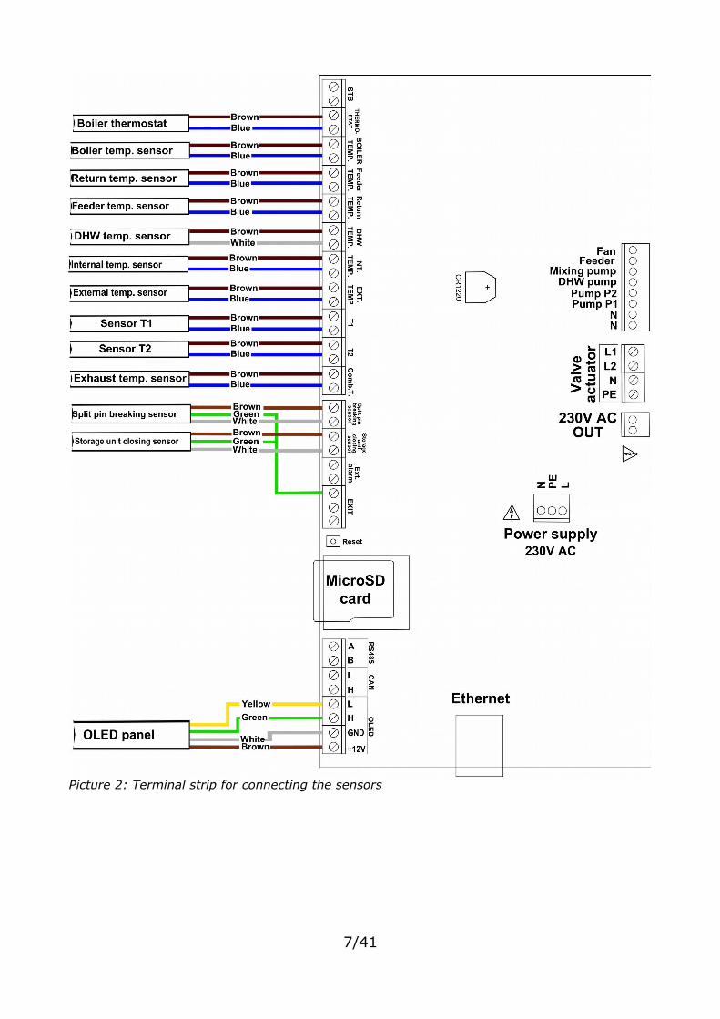
Picture 2: Terminal strip for connecting the sensors
7/41
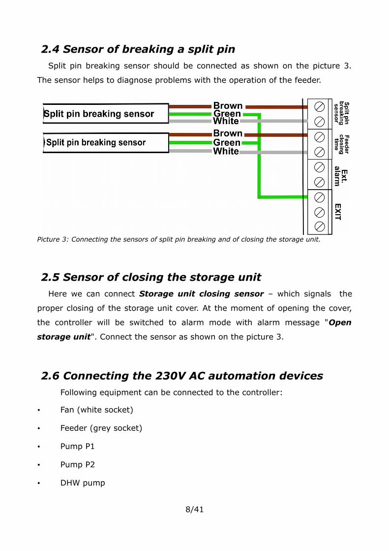
2.4 Sensor of breaking a split pinSplit pin breaking sensor should be connected as shown on the picture 3.
The sensor helps to diagnose problems with the operation of the feeder.
2.5 Sensor of closing the storage unitHere we can connect Storage unit closing sensor – which signals the
proper closing of the storage unit cover. At the moment of opening the cover,
the controller will be switched to alarm mode with alarm message "Open
storage unit". Connect the sensor as shown on the picture 3.
2.6 Connecting the 230V AC automation devicesFollowing equipment can be connected to the controller:
• Fan (white socket)
• Feeder (grey socket)
• Pump P1
• Pump P2
• DHW pump
8/41
Picture 3: Connecting the sensors of split pin breaking and of closing the storage unit.

• Mixing , circulation or boiler feed pump
Follow the instructions given on the casing.
3. Operation of the controller
3.1 Operator panelThe LCD operator panel is equipped with a OLED graphic display, six buttons
and pictograms with LEDS signalizing the operation of the following equipment:
• fan
• feeder
• DHW pump
• pumps P1 and P2
• alarm
• navigating menu
• changing parameter values
• choice confirmation• entering the controller settings from the main screen (pressing the button
for 2s)
• canceling• returning to the main menu• keeping the button pressed (2s) allows to quickly switch the controller's
operating modes: Manual, AUTO
Table 1: Button functions
After 30 minutes of inactivity the display will run a screensaver - the current
time will be displayed on the screen. To go back to the information about the
boiler please press any button on the operator panel.
9/41

3.2 Operator panel - operation levelIn case of incorrect communication between the panel and the controller a
message: "No communication, check the controller connection" will be
displayed.
3.2.1 Home screensThe following information is displayed on the home screen right after
activating the controller:
First screen:
• Type and model of the display
• Version of the display software
Second screen:
• Controller type
• Controller version
10/41
Picture 4: Type and model of the display and software version

The next start window informs about the selected type of the boiler.
At the first start of the controller and after restoring the factory settings
there will also be displayed a screen on which a suitable boiler type should be
selected. The boiler type is given on the boiler name plate.
11/41
Picture 5: Controller type and software version
Picture 6: An example of the boiler type
Picture 7: Boiler type selection screen
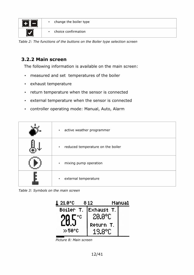
• change the boiler type
• choice confirmation
Table 2: The functions of the buttons on the Boiler type selection screen
3.2.2 Main screenThe following information is available on the main screen:
• measured and set temperatures of the boiler
• exhaust temperature
• return temperature when the sensor is connected
• external temperature when the sensor is connected
• controller operating mode: Manual, Auto, Alarm
• active weather programmer
• reduced temperature on the boiler
• mixing pump operation
• external temperature
Table 3: Symbols on the main screen
12/41
Picture 8: Main screen
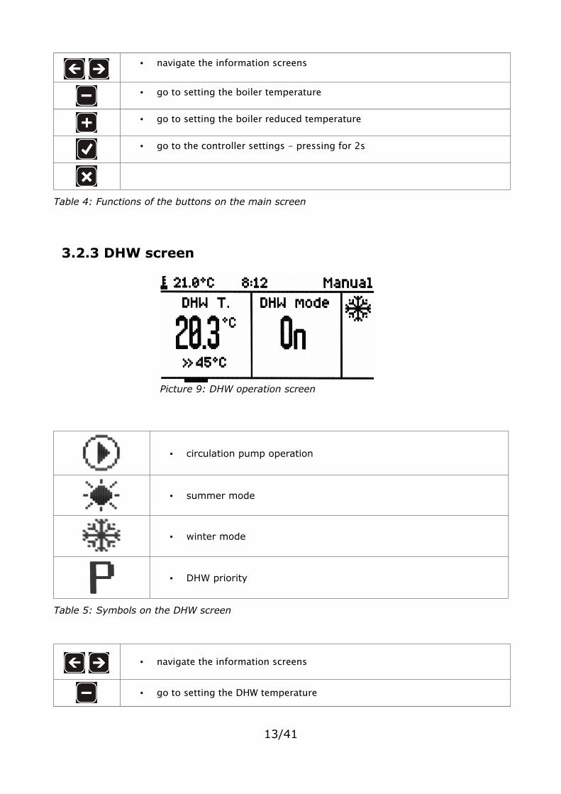
• navigate the information screens
• go to setting the boiler temperature
• go to setting the boiler reduced temperature
• go to the controller settings - pressing for 2s
Table 4: Functions of the buttons on the main screen
3.2.3 DHW screen
• circulation pump operation
• summer mode
• winter mode
• DHW priority
Table 5: Symbols on the DHW screen
• navigate the information screens
• go to setting the DHW temperature
13/41
Picture 9: DHW operation screen

• go to setting the DHW mode
• go to the controller settings - pressing for 2s
• return to the main menu
Table 6: Functions of the buttons on the DHW screen
DHW operating modes:
• Zal – DHW active (ON)
• Wyl – DHW inactive (OFF)
• Prog – DHW active in line with the settings of its programmer
• +1h – DHW active for one hour After this time the DHW returns to its
previous mode.
• +2h – DHW active for two hours After this time the DHW returns to its
previous mode.
3.2.4 Feeder screen
• navigate the information screens
• go to adding new coal batch
• return to the main menu
Table 7: Functions of the buttons on the feeder screen
14/41
Picture 10: Feeder screen

The controller makes it possible to generate entries to the events archive
about new fuel batch fed to the storage unit and a notification of low level of
fuel in the storage unit. Feeder working time is used to deduct it.
3.2.5 CH.1 and CH.2 circuits screenScreens are available depending on the type of CH (central heating) circuit
chosen.
The following information is available on the CH screen:
• measured and set external temperature
• temperature measured and set behind the valve - only for the CH circuit
• valve opening angle - only for the CH circuit
• navigate the information screens
• go to setting the temperature behind the valve
• go to setting the reduced temperature behind the valve
• go to the controller settings - pressing for 2s
• return to the main menu
Table 8: Functions of the buttons on the CH.1 screen
• CH pump operation
15/41
Picture 11: CH.1 circuit screen Picture 12: CH.2 circuit screen

• active room thermostat
• circuit type - central heating (CH) or floor heating
• valve operating mode (only for the CH.1 circuit)
Table 9: Symbols on the CH.1 and CH.2 circuits screen
3.2.6 Network screenThe following information is available on the network screen:
• state of network cable connection
• IP address, mask and gateway
• state of connection to the eSterownik.pl platform:
◦ online – connection is correct
◦ offline – not connected to the platform
16/41
Picture 13: Network settings screen

3.2.7 Alarm screenThe screen lists current alarms.
• navigate the information screens
• alarm review
• confirmation of all alarms
• return to the main menu
• each button mutes audible alarms
Table 10: Functions of the buttons on the alarm screen
An additional device for signaling a controller alert (e.g. an alarm light, a
buzzer) can be connected to the controller.
Input parameters:
• Maximum voltage: 24V DC,
• Maximum load current: 50mA
17/41
Picture 14: Alarm screen
Picture 15: Connection of an additional alarm receiver to the alarm output

3.2.8 Manual control screen
• navigate the information screens
• selection of a device
• turning the device on/off • setting to blower and pressing the button for 2s allows to change Blower
power in manual mode.
• return to the main menu
Table 11: Functions of the buttons on the manual control screen
3.2.9 Operating mode screen
Manual • manual mode is used to manually turn on and off all the devices powered by the controller.
AUTO • operation with auto control of the combustion process
Alarm
• operation of the devices with possible limitations, depending on the alarm type
• return to the auto mode is possible only after removing the technical problem and confirming the alarm
Table 12: Operating modes
18/41
Picture 16: Manual control screen
Picture 17: Operating mode screen
4. Controller parameters
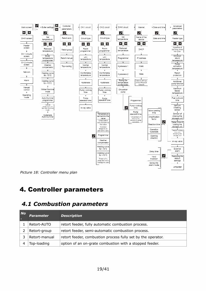
4.1 Combustion parameters
No.
Parameter Description
1 Retort-AUTO retort feeder, fully automatic combustion process.
2 Retort-group retort feeder, semi-automatic combustion process.
3 Retort-manual retort feeder, combustion process fully set by the operator.
4 Top-loading option of an on-grate combustion with a stopped feeder.
19/41
Picture 18: Controller menu plan
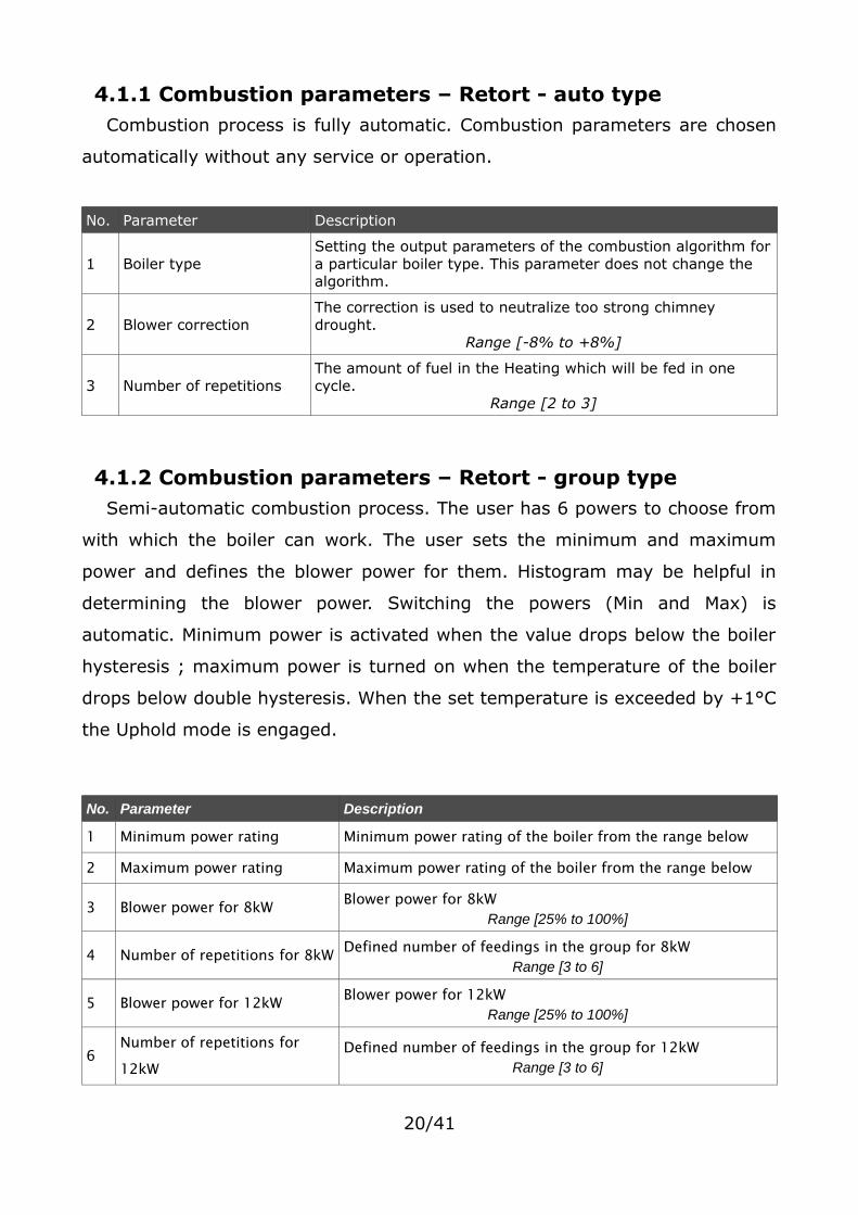
4.1.1 Combustion parameters – Retort - auto typeCombustion process is fully automatic. Combustion parameters are chosen
automatically without any service or operation.
No. Parameter Description
1 Boiler typeSetting the output parameters of the combustion algorithm fora particular boiler type. This parameter does not change the algorithm.
2 Blower correctionThe correction is used to neutralize too strong chimney drought.
Range [-8% to +8%]
3 Number of repetitionsThe amount of fuel in the Heating which will be fed in one cycle.
Range [2 to 3]
4.1.2 Combustion parameters – Retort - group typeSemi-automatic combustion process. The user has 6 powers to choose from
with which the boiler can work. The user sets the minimum and maximum
power and defines the blower power for them. Histogram may be helpful in
determining the blower power. Switching the powers (Min and Max) is
automatic. Minimum power is activated when the value drops below the boiler
hysteresis ; maximum power is turned on when the temperature of the boiler
drops below double hysteresis. When the set temperature is exceeded by +1°C
the Uphold mode is engaged.
No. Parameter Description
1 Minimum power rating Minimum power rating of the boiler from the range below
2 Maximum power rating Maximum power rating of the boiler from the range below
3 Blower power for 8kW Blower power for 8kW Range [25% to 100%]
4 Number of repetitions for 8kW Defined number of feedings in the group for 8kW Range [3 to 6]
5 Blower power for 12kW Blower power for 12kW Range [25% to 100%]
6Number of repetitions for 12kW
Defined number of feedings in the group for 12kW Range [3 to 6]
20/41

7 Blower power for 16kW Blower power for 16kW Range [25% to 100%]
8Number of repetitions for 16kW
Defined number of feedings in the group for 16kW Range [3 to 6]
9 Blower power for 20kW Blower power for 20kW Range [25% to 100%]
10Number of repetitions for 20kW
Defined number of feedings in the group for 20kW Range [3 to 6]
11 Blower power for 25kW Blower power for 25kW Range [25% to 100%]
12Number of repetitions for 25kW
Defined number of feedings in the group for 25kW Range [4 to 9]
13 Blower power for 30kW Blower power for 30kW Range [25% to 100%]
14Number of repetitions for 30kW
Defined number of feedings in the group for 30kW Range [4 to 9]
15 Boiler hysteresis
Boiler temperature hysteresis. Temperature above the setvalue for the boiler – the Uphold mode is engaged;temperature below the set value minus hysteresis of theboiler – going into the Heating mode.
Range [0°C to 5°C]
4.1.3 Combustion parameters – Retort - manual typeThe combustion process is fully automatic. The user sets all the combustion
parameters.
No. Parameter Description
1 Exhaust regulator
This function makes it possible to reduce chimney loss bydecreasing the fan power when a set temperature of exhaust isexceeded.
Range [YES/NO]
2Maximum exhaust temperature
Maximum exhaust temperature which will be sustained by theexhaust thermostat. Exceeding this temperature will result inreduction of the fan performance.
Range [90°C to 500°C]
3 Minimum blower powerMinimum power for which the fan value will be reduced with activeexhaust thermostat.
Range [25% to 100%]
21/41

4 Feeder working time Fuel feeding time in the Heating mode. Range [3s to 30s]
5 Feeder standstill timeThe standstill time in the Heating mode - the standstill betweeneach dose.
Range [10s to 600s]
6 Blower power The power of blower in the Heating mode. Range [25% to 100%]
7 Boiler hysteresis
Boiler temperature hysteresis. Temperature above the set value forthe boiler – the Uphold mode is engaged; temperature below theset value minus Hysteresis of the boiler – going into the Heatingmode.
Range [0°C to 5°C]
4.1.4 Combustion parameters – top-loading typeThe mode of on-grate combustion with a stopped feeder. The algorithm
automatically reduces the blower power when the exhaust temperature
exceeds 350°C and stops the blower when this temperature is higher than
400°C. In case of burning wood in the boiler remove the exhaust sensor from
the flue.
No. Parameter Description
1 Purging time
Up to 8°C above the set temperature the controller makes automaticpurging to remove gases from the chamber (it is very important fortop-loaded boilers). The purging time defines the time duringwhich the blower will be turned on.
Range [0s to 90s]
2Time between each purging
The time between one purging and the next. Range [1min to 15min]
3 Blower powerThe power of the blower whit which it will be turned on in theheating mode.
Range [25% to 100%]
4 Auto regulation
The parameter relates to the temperature range just beforereaching the set value, in which the controller automatically reducesthe blower power. Within this range, together with the rise of thecentral heating temperature, the blower smoothly slows down untilit reaches the level of the set temperature. When the temperaturedrops, the blower speed increases.
Range [0°C to 10°C]
22/41

No. Parameter Description
5 Boiler hysteresis
Boiler temperature hysteresis. Temperature above the set value forthe boiler – the Uphold mode is engaged; temperature below theset value minus Hysteresis of the boiler – going into the Heatingmode.
Range [0°C to 5°C]
4.1.5 Uphold parametersUphold parameters are set for the combustion parameters: Retort auto,
retort group, retort manual. These parameters can be find in the combustion
settings of a particular combustion process (not for top-loaders.)
No.
Parameter Description
1Uphold: Feeder working time
Fuel feeding time in the Uphold mode. Range [3s to 30s]
2Uphold: Feeder standstilltime
The standstill time in the Uphold mode. Range [3min to 360min]
3Uphold: Short break time
The short break time (standstill) of the feeder in the Upholdmode. In this mode the fuel feeding cycle has the followingstages:[WORK-SHORT BREAK] - [WORK-SHORT BREAK]Cyclical work helps to burn down the fuel during the Upholdstage. The number of cycles can be defined in the nextparameter.
Range [5s to 90s]
4Uphold: Number of feeding repetitions
Number of cycle repetitions: [WORK-SHORT BREAK] in theuphold.
Range [1 to 5]
5 Uphold: Blower powerThe power of blower in the Uphold mode.
Range [25% to 100%]
4.1.6 Blower power in manual modeThe parameter allows to change the blower power in the manual mode. In
this mode it is also possible to turn on/off each of the devices connected to the
controller - see point 3.2.8 Manual control screen.
23/41

No.
Parameter Description
6The power of blower in the manual mode.
The power of blower set in the manual mode. Range [25% to 100%]
4.2 Boiler settings
No. Parameter Description
1 Set temperature The set temperature of water at the boiler outlet.Range [42°C to 80°C]
2 Reduced temperature
The value by which the set temperature of the boiler will bereduced when there is a reduced temperature set in a boilerprogrammer.
Range [0°C to 25°C]
3Boiler temperature programmer
The programmer is used to set the water temperature at theboiler outlet for each weekday.Programming the reduced temperature has also an impact on thework of the weather compensator.
4 Weather compensator
Activating the weather compensator. The compensator deductsan adequate temperature set for the boiler, based on outdoortemperature and a heating curve. Connecting wired or remotetemperature sensors BT2 is a prerequisite for this function. Thetemperature set for the weather compensator is updated every 5minutes.
Range [YES/NO]
5 Heating curve for -10°CThe temperature set for the boiler with the outdoor temperature-10°C.
Range [42°C to 80°C]
6 Heating curve for +10°CThe temperature set for the boiler with the outdoor temperature+10°C.
Range [42°C to 80°C]
7 Winter/Summer mode
Defining the operating mode for the DHW circuit. Options:• Winter - both CH and DHW circuits working• Summer - only DHW circuit working• Auto-Summer - Winter or Summer mode, depending on
the outdoor temperature Connecting wired or remotetemperature sensors BT2 is a prerequisite for thisfunction.
8 Auto-Summer programmer
Time settings of the mode for a particular weekday:
• Winter
• Summer
24/41
• Auto-Summer
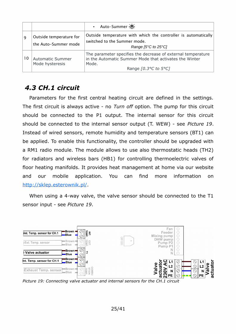
9 Outside temperature for the Auto-Summer mode
Outside temperature with which the controller is automaticallyswitched to the Summer mode.
Range [5°C to 25°C]
10 Automatic Summer Mode hysteresis
The parameter specifies the decrease of external temperature in the Automatic Summer Mode that activates the Winter Mode.
Range [0.3°C to 5°C]
4.3 CH.1 circuitParameters for the first central heating circuit are defined in the settings.
The first circuit is always active - no Turn off option. The pump for this circuit
should be connected to the P1 output. The internal sensor for this circuit
should be connected to the internal sensor output (T. WEW) - see Picture 19.
Instead of wired sensors, remote humidity and temperature sensors (BT1) can
be applied. To enable this functionality, the controller should be upgraded with
a RM1 radio module. The module allows to use also thermostatic heads (TH2)
for radiators and wireless bars (HB1) for controlling thermoelectric valves of
floor heating manifolds. It provides heat management at home via our website
and our mobile application. You can find more information on
http://sklep.esterownik.pl/.
When using a 4-way valve, the valve sensor should be connected to the T1
sensor input - see Picture 19.
25/41
Picture 19: Connecting valve actuator and internal sensors for the CH.1 circuit
An external thermostat can be connected to the controller. The thermostat
should be connected to the T.WEW (internal temperature) contacts of the
controller board (in the place of an internal sensor). The thermostat is required
to have an potential-free contact. If the thermostat is connected, it produces a
controller reaction by switching the contacts. When the contacts are in a close
state the boiler is set to heat. With an open state of the contacts the controller
changes its mode to cooling, moreover the P1 pump can be in one of these
modes: cyclic operation, continuous operation or turned off.
No. Parameter Description
1 Circuit type
The definition of CH.1 circuit operation explains the following workparameters:
● CH pump - continuous work of P1 pump ● CH pump + room regulator - P1 pump working based on the
inside temperature coming from the programmer. Connectingwired or remote humidity and temperature sensors BT1 is a prerequisite for this function. Ability to use external thermostat.
● Floor pump - P1 pump working as a floor pump The P1 pump working based on the inside temperature coming from the programmer. Connecting wired or remote humidity and temperature sensors BT1 is a prerequisite for this function. Ability to use external thermostat.
● CH pump + 4D - P1 pump and 4-way valve● CH pump + 4D + room regulator - P1 pump working with 4-
way valve based on the inside temperature coming from the programmer. Connecting wired or remote humidity and temperature sensors BT1 is a prerequisite for this function. Ability to use external thermostat.
● Floor pump - 4-way valve and P1 pump as a floor pump● Floor pump + 4D + room regulator - P1 pump working as a
floor pump with 4-way valve based on inside temperature coming from the programmer. Connecting wired or remote humidity and temperature sensors BT1 is a prerequisite for this function. Ability to use external thermostat.
2Room controller type
This parameter is defined as a source of information for the roomcontroller:
• Temperature sensor – the information about temperature ispassed from an internal wired or wireless BT1 sensor. Aweekly table of set point temperature for the room should be
26/41
defined.• External thermostat – the information about heating mode is
received from an external thermostat. That appliance replacesthe weekly set point temperature table.
Range [Internal sensor/Thermostat]
3 Programmer
The parameter is used to set temperature for each weekday.Connecting wired or remote temperature sensors BT1 is aprerequisite for this function. Achieving the desired roomtemperature rearranges the controller in cooling mode - the ability tostop the pump P1 / P2. Ability to use external thermostat.
4 Low temperatureThe parameter determines the value of a reduced temperature (e.g. night) in a room. Does not apply to external thermostat
Range [5°C to 35°C]
5 Normal temperatureThe parameter determines the value of a normal temperature (e.g. day) in a room. Does not apply to external thermostat
Range [5°C to 35°C]
6Comfortable temperature
The parameter determines the value of a comfortable (increased) temperature in a room. Does not apply to external thermostat
Range [5°C to 35°C]
7 Hysteresis
The parameter determines the value by which the internaltemperature should be decreased for the controller to decide that aroom extra heating procedure should be started.
Range [0°C to 5°C]
8 Pump working time
The parameter determines the working time of the P1 pump for anactive Programmer. Setting 0mm means that the P1 pump will beturned off after reaching the set temperature in the room.
Range [0min to 240min]
9Pump standstill time
The parameter determines the standstill time of the P1 pump for anactive Programmer.
Range [1min to 250min]
10 4-way valveGroup of parameters concerning the operation of the 4-wayvalve (only for the CH.1 circuit)
10.1 Temperature set behind the valve
Water temperature set behind the valve.Range [20°C to 80°C]
10.2Temperature reduced behind the valve
The value by which the set temperature behind the valve will bereduced when there is set a reduced temperature in a programmer.
Range [0°C to 25°C]
10.3Maximum temperature behindthe valve
Reaching this temperature results in generating the alarm: High
temperature behind the 4-way valve. The valve is additionally closed for floor heating.
Range [20°C to 80°C]
27/41

10.4 Programmer
The programmer is used to set the water temperature behind thevalve for each weekday.Programming the reduced temperature has also an impact on thework of the weather compensator.
10.5 Weather compensator
Activating the weather compensator. The compensator deducts an adequate temperature set behind the valve, based on outdoor temperature and a heating curve. Connecting an external sensor is a
prerequisite for this function. The temperature set for the weather compensator is updated every 5 minutes.
Range [YES/NO]
10.6 Heating curve for -10°C
The temperature set behind the valve with the outdoor temperature -10°C.
Range [20°C to 80°C]
10.7 Heating curve for +10°C
The temperature set behind the valve with the outdoor temperature +10°C.
Range [20°C to 80°C]
10.8Stopping the pump after extra heating the room
The parameter determines if after reaching the temperature in the room, the pump should stop or only reduce the temperature behind the valve.
Range [YES/NO]
4.4 CH.2 circuit screenParameters for the second central heating circuit are defined in these
settings. The parameters are the same as for the first CH.1 circuit. It is also
possible to turn off this circuit. The receiver for this circuit should be connected
to the P2 output. The internal sensor for this circuit should be connected to the
T2 sensor input - see Picture 19. It is not possible to define the valve actuator
for this circuit. Instead of wired sensors, remote humidity and temperature
sensors (BT1) can be applied. To enable this functionality, the controller should
be upgraded with a RM1 radio module. The module allows to use also
thermostatic heads (TH2) for radiators and wireless bars (HB1) for controlling
thermoelectric valves of floor heating manifolds. It provides heat management
at home via our website and our mobile application. You can find more
information on http://sklep.esterownik.pl/.
An external thermostat can be connected to the controller. The thermostat
should be connected to the T2 (internal temperature) contacts of the controller
28/41

board (in the place of an internal sensor). The thermostat is required to have
an potential-free contact. If the thermostat is connected, it produces a
controller reaction by switching the contacts. When the contacts are in a close
state the boiler is set to heat. With an open state of the contacts the controller
changes its mode to cooling, moreover the P1 pump can be in one of these
modes: cyclic operation, continuous operation or turned off.
4.5 DHW circuit
No.
Parameter Description
1 Set temperature The temperature set for the DHW storage unit. Range [20°C to 60°C]
2 Reduced temperature
The value by which the set temperature of the domestic hot waterwill be reduced when there is too low temperature set on theweekly chart.
Range [0°C to 25°C]
3 ProgrammerThe programmer is used to set the temperature of DHW for eachweekday.
4 Hysteresis #1 The hysteresis of starting the DHW loading pump.Range [0°C to 10°C]
5 Hysteresis #2
The hysteresis for achieving the DHW priority - activating the DHWloading pump and stopping the P1 and P2 pump. Choosing 30°C
deactivates the priority option.Range [0°C to 30°C]
6Rising the temperature on the boiler
Setting the rising (increase) of the set temperature on the boiler inorder to warm up water in the storage unit with an active DHWpriority.
Range [0°C to 20°C]
7 Circulation pumpThe group of parameters related to the operation of the DHW circulation pump.
7.1 Programmer
The programmer is used to set the temperature of the DHWcirculation pump for each weekday. Options:
• - pump turned off
• - pump turned on
• - cyclical work of the pump in accordance with the 7.2
and 7.3 parameters.
29/41
7.2 Pump working time Pump working time for the cyclic mode.Range [1min to 240min]
7.3 Pump standstill time Pump standstill time for the cyclic mode. Range [1min to 240min]
7.4Temperature of startingthe circulation pump operation
The prerequisite for starting the circulating pump - minimum temperature in the DHW storage unit. Hysteresis for turning off 0.5°C
Range [25°C to 60°C]
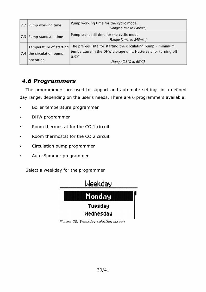
4.6 ProgrammersThe programmers are used to support and automate settings in a defined
day range, depending on the user's needs. There are 6 programmers available:
• Boiler temperature programmer
• DHW programmer
• Room thermostat for the CO.1 circuit
• Room thermostat for the CO.2 circuit
• Circulation pump programmer
• Auto-Summer programmer
Select a weekday for the programmer
30/41
Picture 20: Weekday selection screen
• weekday selection
• confirm the selection and go to the programmer
• return
Table 13: The functions of the buttons for the weekday selection screen for the programmer
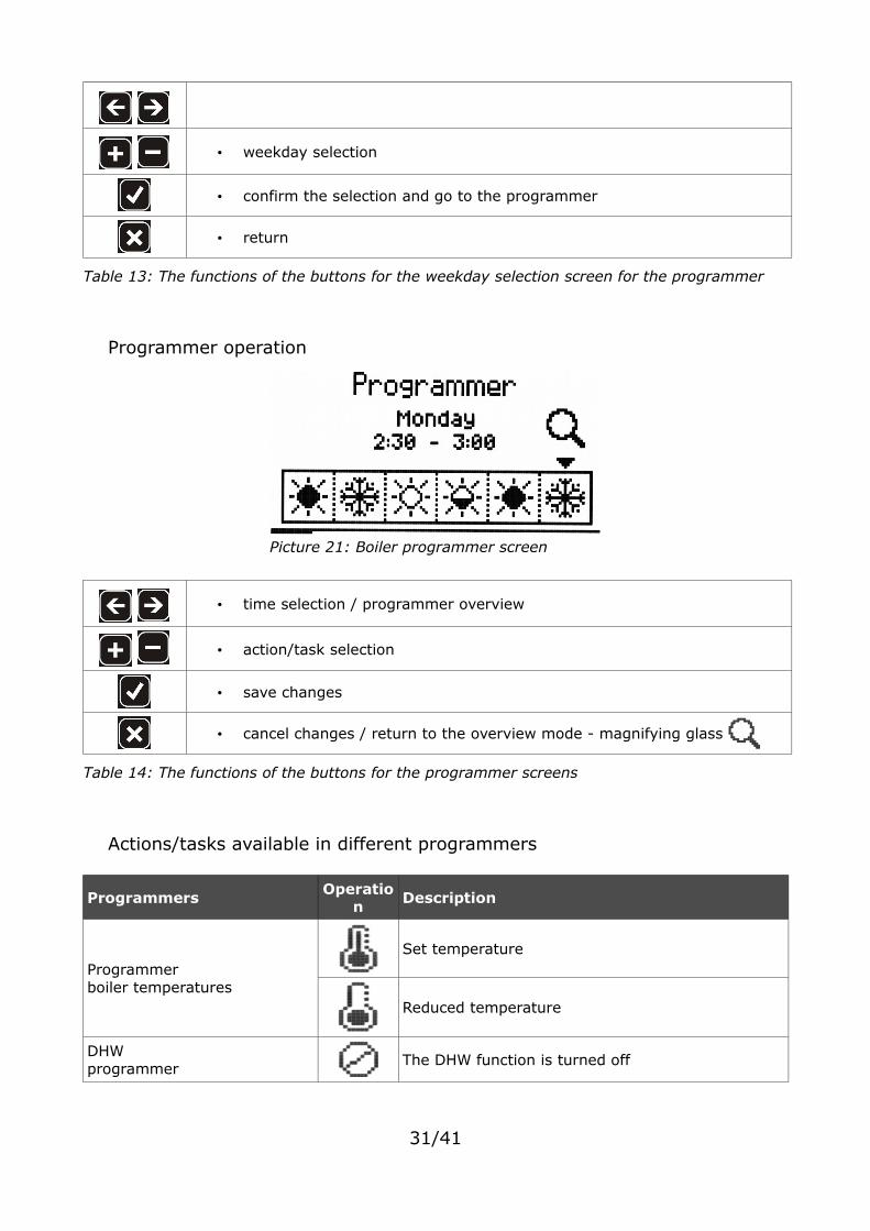
Programmer operation
• time selection / programmer overview
• action/task selection
• save changes
• cancel changes / return to the overview mode - magnifying glass
Table 14: The functions of the buttons for the programmer screens
Actions/tasks available in different programmers
Programmers Operation
Description
Programmerboiler temperatures
Set temperature
Reduced temperature
DHW programmer
The DHW function is turned off
31/41
Picture 21: Boiler programmer screen
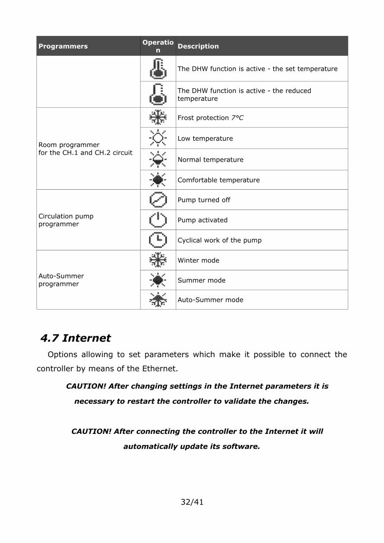
Programmers Operation
Description
The DHW function is active - the set temperature
The DHW function is active - the reduced temperature
Room programmerfor the CH.1 and CH.2 circuit
Frost protection 7°C
Low temperature
Normal temperature
Comfortable temperature
Circulation pump programmer
Pump turned off
Pump activated
Cyclical work of the pump
Auto-Summer programmer
Winter mode
Summer mode
Auto-Summer mode
4.7 InternetOptions allowing to set parameters which make it possible to connect the
controller by means of the Ethernet.
CAUTION! After changing settings in the Internet parameters it is
necessary to restart the controller to validate the changes.
CAUTION! After connecting the controller to the Internet it will
automatically update its software.
32/41
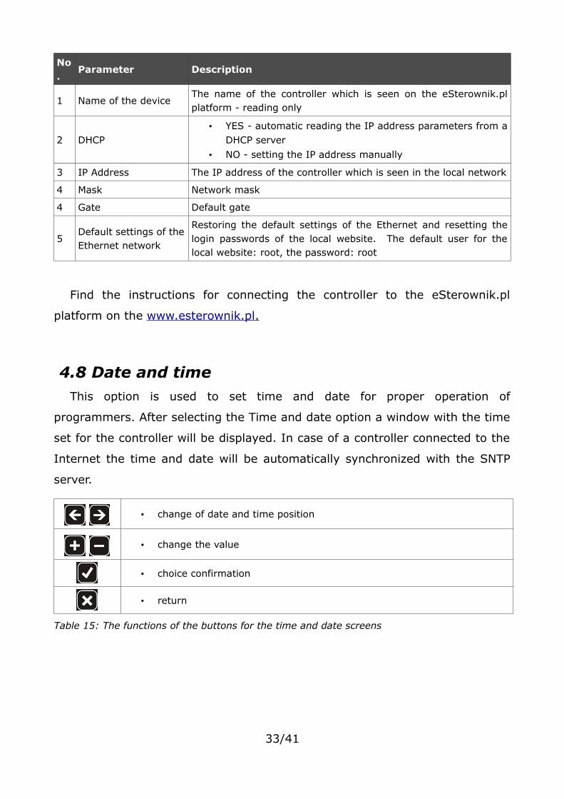
No.
Parameter Description
1 Name of the deviceThe name of the controller which is seen on the eSterownik.plplatform - reading only
2 DHCP• YES - automatic reading the IP address parameters from a
DHCP server
• NO - setting the IP address manually
3 IP Address The IP address of the controller which is seen in the local network
4 Mask Network mask
4 Gate Default gate
5Default settings of theEthernet network
Restoring the default settings of the Ethernet and resetting thelogin passwords of the local website. The default user for thelocal website: root, the password: root
Find the instructions for connecting the controller to the eSterownik.pl
platform on the www.esterownik.pl .
4.8 Date and timeThis option is used to set time and date for proper operation of
programmers. After selecting the Time and date option a window with the time
set for the controller will be displayed. In case of a controller connected to the
Internet the time and date will be automatically synchronized with the SNTP
server.
• change of date and time position
• change the value
• choice confirmation
• return
Table 15: The functions of the buttons for the time and date screens
33/41

4.9 Advanced parameters
No. Parameter Description
1 Feeder type
Selection of the feeder operation (combustion algorithm):• Retort auto – retort feeder, fully automatic combustion
process• Retort Group – retort feeder, semi-automatic combustion
process• Retort Manual – retort feeder, combustion process fully set
by the operator• Top-loaded – option of an on-grate combustion
2Algorithm of damping down the boiler
Detection of boiler damping down in the Uphold and Heating mode, based on the exhaust temperature:
• Inactive – turning off the boiler damping down detection• Heating only – boiler damping down detection only in the
Heating mode• Uphold only – boiler damping down detection only in the
Uphold mode• Always – boiler damping down detection both in the
Heating and Uphold mode.
3Minimum return temperature
The minimum value of the return temperature below which themixing pump will be activated
Range [35°C to 60°C]
4Pump activation temperature
The value of the outlet water temperature below which thefollowing pumps can be activated: P1, P2, mixing, DHW, boilerfeed pump
Range [35°C to 60°C]
5 Return protection • DHW pump – the DHW pump acts as a storage unit loadingpump and a mixing pump
• Mixing pump – using the mixing pump.Pump turning off hysteresis amounts 2°C
• 4-wayvalve – return protection by means of a 4-way valveIt is necessary in this case to use a gravity flow of water inthe small 4-way valve cycle from the boiler side. Otherwisean additional circulation pump should be installed. In case of using a 3-way valve it is not possible to have areturn protection and a smooth temperature control behindthe valve at the same time. When a CH pump is installed witha 3-way valve, temperature control behind the valve ispossible, but a return protection is not. When a CH pump isinstalled with a 3-way valve, a return protection is possible,but temperature control behind the valve is not. Therefore, a 4-way valve is necessary to have both a return
34/41

No. Parameter Description
protection and a smooth temperature control behind thevalve at the same time.
6Additional pump function
• mixing pump – sustaining the minimum temperature of thewater returning to the boiler
• circulation pump – it is intended to ensure a constant watercirculation from the storage unit to the point of drawingwater
• boiler pump – small cycle pump between the boiler and abuffer.
7Maximum feeder temperature
The limiting temperature of the feeder exceeding which willactivate an alarm
Range [40°C to 110°C]
8 Fuel outburst timeThe time of activating the feeder after the following alarmappeared: Fuel ignition in the feeder.
Range [1min to 10min]
9Split pin breaking sensor
Activating the function of feeder damage detectionRange [YES/NO]
10Sensor of closing the storage unit
Activating the function of open storage unit detectionRange [YES/NO]
11Delay time of closing the storage unit
The time after which an Open feeder alarm will be reportedRange [0s to 60s]
12Feeder working time until emptying the storage unit
The time of feeder operation after which the storage unit will be emptied and the following alarm reported: Empty storage unit. Setting 0min for the parameter disables the function.
Range [0min to 999min]
13 4-way valveGroup of parameters concerning the operation of the 4-way valve
13.1 Valve opening timeThe time when the valve is fully open. This time is given on the valve name plate.
Range 30s to 600s
13.2 Amplification factor
The amplification factor of the difference between the set and the currently measured temperatures. The higher the factor, the bigger the individual steps of the valve.
Range [0 to 2.0]
13.3 Reaction time Defines the time after which the valve corrects its positionRange [10s to 600s]
13.4 Operation hysteresis If the difference between the set and the measured temperature is lower than the value of Operation hysteresis, the valve does not correct its position
35/41
No. Parameter Description
Range [0°C to 10°C]
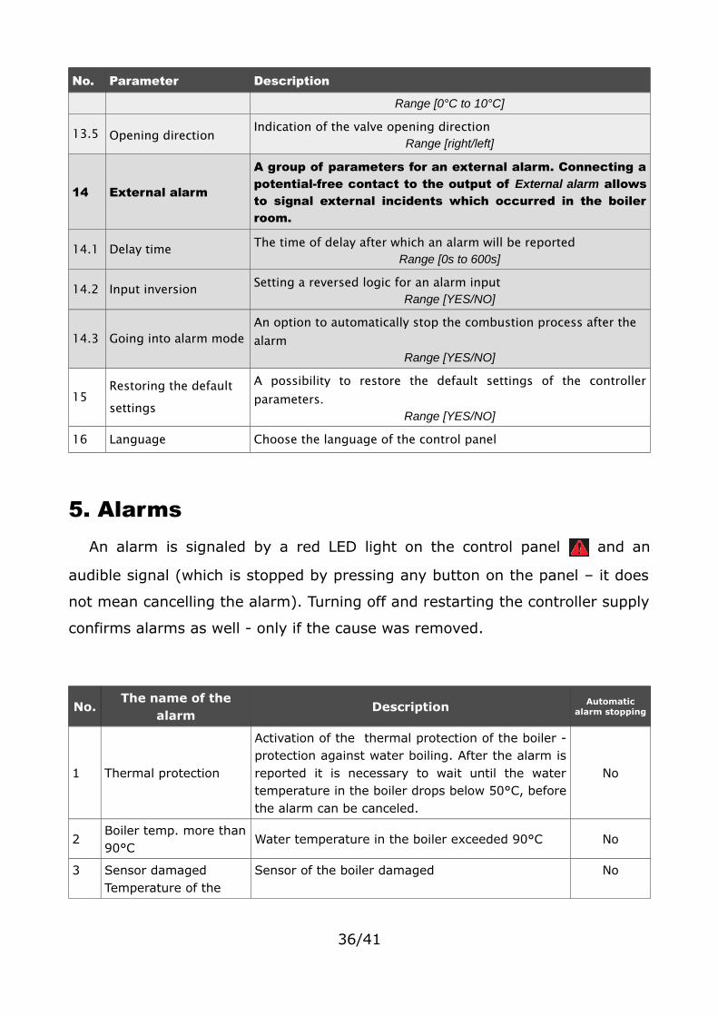
13.5 Opening direction Indication of the valve opening directionRange [right/left]
14 External alarm
A group of parameters for an external alarm. Connecting apotential-free contact to the output of External alarm allowsto signal external incidents which occurred in the boilerroom.
14.1 Delay time The time of delay after which an alarm will be reportedRange [0s to 600s]
14.2 Input inversion Setting a reversed logic for an alarm inputRange [YES/NO]
14.3 Going into alarm modeAn option to automatically stop the combustion process after the alarm
Range [YES/NO]
15Restoring the default settings
A possibility to restore the default settings of the controllerparameters.
Range [YES/NO]
16 Language Choose the language of the control panel
5. AlarmsAn alarm is signaled by a red LED light on the control panel and an
audible signal (which is stopped by pressing any button on the panel – it does
not mean cancelling the alarm). Turning off and restarting the controller supply
confirms alarms as well - only if the cause was removed.
No.The name of the
alarmDescription Automatic
alarm stopping
1 Thermal protection
Activation of the thermal protection of the boiler -protection against water boiling. After the alarm isreported it is necessary to wait until the watertemperature in the boiler drops below 50°C, beforethe alarm can be canceled.
No
2Boiler temp. more than90°C
Water temperature in the boiler exceeded 90°C No
3 Sensor damaged Temperature of the
Sensor of the boiler damaged No
36/41

No.The name of the
alarmDescription Automatic
alarm stopping
boiler
4Sensor damaged DHW temp.
DHW sensor damaged Yes
5Sensor damaged return temp.
Return sensor damaged Yes
6Internal sensor damaged
Internal sensor damaged Yes
7External sensor damaged
External sensor damaged Yes
8Sensor damaged feeder temp.
Feeder sensor damaged No
9Sensor damaged exhaust temp.
Exhaust sensor damaged No
10 Sensor damaged T1
T1 sensor damaged When the sensor acts as a valve sensor, the failure of the circuit in:
• floor heating - the valve will be closed• central heating - the valve will be open
Yes
11 Sensor damaged T2 T2 sensor damaged Yes
12Fuel ignition in the feeder
Fuel ignition in the feeder – exceeding themaximum temperature of the feeder
No
13High feeder temperature
Too high feeder temperature Yes
14 Boiler put out
The boiler was put out - the alarm relates to theUphold and Heating mode. When:- in the Heating mode - the exhaust temperaturedoes not exceed 50°C in 30min. Check if the boilerexchanger and the flue are clean.- in the Uphold mode - after starting the upholdprocedure the exhaust temperature does notincrease by 5°C. Incorrectly set parameters of theUphold mode.
No
15 Dirty boilerThe boiler got dirty - check if the boiler exchangerand the flue are clean.
No
16High exhaust temperature
Too high exhaust temperature - check if thecomponents of the boiler exchanger are properlymounted.
Yes
17 IP addresses conflictConflict of IP addresses - this IP address isalready reserved
Yes
18 SD card error No microSD card or missing Yes
19 External alarm Open/close CONT contact on the controller plate– universal alarm input. When the alarm occurs
No
37/41

No.The name of the
alarmDescription Automatic
alarm stopping
check if to the CONT input a sensor has not beenconnected or Advanced parameters – Externalalarm - Input inversion has not been changedto Yes
20 Empty storage unit
Low level of fuel in the storage unit - this alarmdoes not stop the boiler work. It is used formaking statistics of fuel combustion. The alarmoption is disabled by setting Feeder workingtime until emptying the storage unit to 0min.Alarm is cleared by adding a new batch of fuel.
No
21 STB External thermal protection of the boiler No
22 Feeder errorThe feeder is not connected or there was a powersupply failure in this circuit
No
23 Broken split pin
A problem with the feeder – a broken split pin,feeder jamming (e.g. a stone in the fuel). Checkthe split pin and see if the feeder rotates afterturning it on. The alarm appears also when nosensor is connected or when it is incorrectlyconnected.
No
24 Open storage unit
Open (not closed) feeder cover Check if the feedercover is well closed. The alarm appears also whenno sensor is connected or when it is incorrectlyconnected.
Yes
25High temperature behind the 4-way valve
Only for floor heating: Maximum temperaturebehind the 4-way valve has been exceeded. Thevalve can be closed for floor heating.
No
38/41

Declaration of conformity
ELEKTRO-SYSTEM s.c. with its official seat at ul. Sienkiewicza 25 in Kutno hereby declares that
the product:
Adaptive controller DEFRO SMART II V3.5
complies with the provisions of the following European Directives:
• Directive 2006/95/EC of the European Parliament and of the
Council on the harmonization of the laws of Member States relating to electrical
equipment designed for use within certain voltage limits
• Directive 2004/108/EC of the European Parliament and of the
Council on the approximation of the laws of the Member States relating to
electromagnetic compatibility and repealing Directive 89/336/EEC
Compliance with these directives is ensured through respecting the following standards:
PN-EN 60730-2-9:2006 in conjunction with PN-EN 60730-1:2002 + A1:2008 + A2:2009 +
A12:2004 + A13:2005 + A14:2006 + A15:2009 + A16:2009 + Ap1:2007
IEC 60730-2-9:2008 (Third Edition) in conjunction with IEC 60730-1:1999 (Third Edition) +
A1:2003+ A2:2007
The last two digits of the number of the year in which the CE marking was affixed: '15
This declaration is not a guarantee of product properties within the meaning of the Product
Liability Law. Safety requirements defined in the Operations Manual must be adhered to.
In accordance with Low Voltage Directive, the installation and connection of the products with
the CE marking made in line with the Operations Manual must comply to the requirements
stipulated in Electromagnetic Compatibility Directive (EMC).
Kutno, dated 10-08-2015
39/41
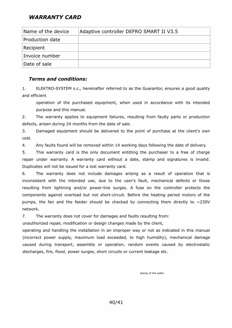
WARRANTY CARD
Name of the device Adaptive controller DEFRO SMART II V3.5
Production date
Recipient
Invoice number
Date of sale
Terms and conditions:
1. ELEKTRO-SYSTEM s.c., hereinafter referred to as the Guarantor, ensures a good quality
and efficient
operation of the purchased equipment, when used in accordance with its intended
purpose and this manual.
2. The warranty applies to equipment failures, resulting from faulty parts or production
defects, arisen during 24 months from the date of sale.
3. Damaged equipment should be delivered to the point of purchase at the client's own
cost.
4. Any faults found will be removed within 14 working days following the date of delivery.
5. This warranty card is the only document entitling the purchaser to a free of charge
repair under warranty. A warranty card without a date, stamp and signatures is invalid.
Duplicates will not be issued for a lost warranty card.
6. The warranty does not include damages arising as a result of operation that is
inconsistent with the intended use, due to the user's fault, mechanical defects or those
resulting from lightning and/or power-line surges. A fuse on the controller protects the
components against overload but not short-circuit. Before the heating period motors of the
pumps, the fan and the feeder should be checked by connecting them directly to ~230V
network.
7. The warranty does not cover for damages and faults resulting from:
unauthorized repair, modification or design changes made by the client,
operating and handling the installation in an improper way or not as indicated in this manual
(incorrect power supply, maximum load exceeded, to high humidity), mechanical damage
caused during transport, assembly or operation, random events caused by electrostatic
discharges, fire, flood, power surges, short circuits or current leakage etc.
stamp of the seller
40/41
Elektro-System s.c.
ul. Sienkiewicza 25
99-300 Kutno
Tel: +48 24 253 76 63
Tel: +48 24 355 05 63
Mob: +48 605 780 882
Fax: +48 24 355 05 73
www.eSterownik.pl
41/41