deformation theory for elastic-plastic buckling analysis of plates under nonproportional planar...
TRANSCRIPT
Comprrlrrs & Stnrttrms Vol. 22. No. 2. pp. 131-149. 1986 Printed in Great Britain.
0045-7949186 $3.00 + .OO 0 1986 Pergamon Press Ltd.
DEFORMATION THEORY FOR ELASTIC-PLASTIC BUCKLING ANALYSIS OF PLATES UNDER NON-
PROPORTIONAL PLANAR LOADING
H. A. EL-GHAZALY and A. N. SHERBOURNE University of Waterloo, Ontario, Canada
(Received 2 I July 1984)
Abstract-Deformation theories are known to give solutions similar to flow theory for proportional loading where the components of the stress tensor at all points grow proportionally. However, if buckling is involved, deformation theories generally give better agreement with experiments. In this study, a deformation theory has been successfully employed for the elastic-plastic buckling analysis of plates under nonproportional external loading and nonproportional stresses. Loading, unloading, and reloading situations have been conveniently considered via conducting multistage analysis after casting the constitutive relations of a deformation theory in an incremental form. In order to achieve an economical solution the modified Newton-Raphson method has been generally used when the structure is loading (or reloading) everywhere while the initial stress method has been employed if unloading due to changes in the external loads takes place. The procedure has been applied in several cases and displayed accuracy and reliability. Three cbmparisons onstrate the applicability of the integrated procedure.
with experiments ark-shown to dem-
NOMENCLATURE 6w,.,. 6w3.v
area of the plate middle surface @WI finite element planar strain-displacement matrix X, Y, and Z planar continuous strain-displacement dif- ferential operator matrix vector of infinitesimal virtual curvatures
Greek
matrix moduli in the inelastic range [&L-I - L&J modulus of elasticity secant modulus from a uniaxial stress-strain relationship total effective strain elastic stress-strain matrix (plane stress) jth load increment global elastic bending stiffness matrix global geometric bending stiffness matrix finite element planar tangent stiffness matrix structural global planar tangent stiffness ma- trix ratio between the purely elastic stresses and the total stress increment total number of iterations vector of infinitesimal internal moments stress resultants in X and Y directions, re- spectively shear stress resultant in the X-Y plane vector of planar continuous loading element load vector due to difference be- tween elastic and inelastic stresses rth iteration vector of global nodal planar load increment part of the boundary on which boundary tractions are prescribed displacements along X, Y, and Z axes, re- spectively volume of structure finite element volume rate of change of w w.r.t. X and Y axes, re- spectively virtual slope w.r.t. X and Y axes, respec- tively
slope variation w.r.t. X and Y axes, respec- tively vector of infinitesimal global displacements (out of plane) global axes
shear strain vector of continuous planar displacements vector of global planar nodal displacement increments vector of virtual planar continuous displace- ment increments strain component in the X and Y directions, respectively very small value to define termination of it- erations tensor of elastic strain increment tensor of plastic strain increment strain tensor incremental disturbance element total strain element strain increment (&I&) - I Poisson’s ratio effective stress stress components in the Xand Ydirections, respectively yield stress uniaxial yield stress stress tensor incremental disturbance element total stresses element elastic stress increment element stresses that have to be equilibrated by body forces shear stress components in the X-Y plane
1. INTRODUCTION
Attempts to understand the problem of plate buck- ling in the plastic range go back to the early 1940s. While Handelman and Prager[ 1] adopted a flow the-
131
132 H. A. EI -GHAI,U ‘I and A. N. SHERROURN~
ory. which is mathematically consistent, to for- mulate a solution for plastic plate buckling, Bijlaard[?]. Shanley[J]. and StowelI] employed a deformation theory, which has general validity for proportional loading, and obtained results more consistent with experiments. Shanley[S], in a com- prehensive paper, showed the inapplicability of for- mulation for plate plastic buckling based on a flow theory and proved, via physical argument. the ap- plicability of the counter formulation based on de- formation theory. A pioneering paper by Budi- ansky(61 showed that, under certain conditions. a deformation theory may still be used for quasi-pro- portional loading without violating Drucker’s basic requirements]71 for plastic deformations. Sewell drew attention to the significant sensitivity of the buckling stress to the shape of the yield surface@] and later published a paper[9] where he constructed a plastic flow rule at a yield vertex: in doing so, the incipient shear modulus becomes less than its elas- tic value. In fact, Ref. [9] is believed to be an im- portant extension and application to the results ob- tained previously by Budiansky[h]. Dubey. in a series of publications( IO, I I. 12, 131 diagnosed. in depth, the difficulty of using a flow theory in plate plastic buckling problems, and suggested new for- mulations which essentially lower the value of the effective shear modulus, and hence give better ea- timates of the buckling stress in the plastic range.
Researchers adopting a flow theory in the frame- work of large deflection analysis and using imper- fections to lower the value of the buckling load are faced with the inevitable question about the distri- bution of these imperfections prior to applying ex- ternal loading. Examples of this approach are re- ported in [l4. 15, 16, 17. 181. In Ref. 1181, Crisfield explicitly indicated that the elastic buckling mode is to be used as a guide to obtain imperfection dis- tributions for stability analysis in the plastic range; the authors disagree with Crisfield’s assertion. In simple structures, such as pin-ended columns and square plates. the elastic and the plastic buckling modes may be similar. For general plate geome- tries, however. the plastic buckling mode is often different from the elastic buckling mode. and hence assuming imperfection distributions similar to the elastic buckling mode may lead to erroneous re- sults. In fact. this is a major criticism in this ap- proach, as the stability analysis becomes totally de- pendent on the imperfection distribution. which is known to assume a random pattern.
Shrivastava[ 191 tried to reconcile the differences between the results of the buckling stress as ob- tained by the two theories of plasticity by including shear effects: however, the flow theory continued to give much higher buckling stresses. The good agreement obtained between deformation theory and experimental results(201 tempted other re- searchers, such as Isakson c’t rr1.[21]. to use this theory in a general discrete element analysis for plate structures. Stanton and Schmit(221 adopted an
energy search procedure in conjunction vvith a Hencky-Nadai stress-total strain law and a discre- tized potential energy function to study the elasto- plastic bending of plates. More recently. ‘I‘ang(23] used a deformation theory for the elasto-plastic large deformation of thin shells by employing a gra- dient search method.
2. PROBLEM STATEMEN’I
The problem of plastic buckling is indeed con- troversial. While a flow theory. which is mathe- matically accepted, grossly overestimates the buck- ling load, especially for relatively thick platey, deformation theories, on the other hand, show bet- ter agreement with experimental results. even though they contain inconsistencies regarding the development of plastic deformations. It has be- come. by now, physically accepted that plastic strains are stress-history dependent and that un- loading from a plastic state causes permanent re- sidual strains. This stems from the following two inequalities[24] which are the basis of flow theory formulations.
do;;(d+ + de:;) > 0
du. de!’ 2 0. ,I 1,
(I)
(2)
The first inequality indicates that positive work is done during the application of the structural dis- turbance denoted by (da;,. de;,). The second ine- quality implies that, if the external agency causing do;,, is removed, the elastic component de); will be completely recovered. Deformation theory formu- lations do not account for the second inequality. and assume that there is a regular progression ol plastic deformations and, therefore, that no se- quential “loading-unloading” of any yield mode oc- curs over the loading history.
The present study aims at presenting an inte- grated finite element procedure for elastic-plastic buckling which employs a deformation theory in conjunction with the appropriate numerical tech- niques in order to handle general loading-unloading situations depending on the history of external ap- plied loading. The article concludes with a brief de- scription of experimental tests and their compari- son with the results obtained analytically.
3. FORMULATION
In Ref. 1251, it was shown that inelastic bifur- cation in plane-stress problems may occur as a re- sult of(i) Symmetric mode due to necking. (ii) Anti- symmetric mode due to buckling. and (iii) Surface instability. Since structural steels usually possess
sufficient ductility[26]. steel plates subjected to pre- dominantly compressive forces are liable to fail by buckling rather than excessive plastic deforma- tions.
Deformation theory for elastic-plastic buckling analysis of plates 133
3. I Planar analysis
For buckling analysis in the plastic range, the planar stress distribution needs to be delineated in order to check the stability of the planar stress state. When the stresses are everywhere elastic, the principle of virtual work yields the following con- tinuous force-deformation relationship in the pres- ence of a perturbation {SA},
j-” @A} [BIT [El @I (4 dV = j-, @A}’ 0’) dS,>
(3)
where [B] is a continuous planar strain-displace- ment differential operator matrix, {A} and {6A} are the actual and virtual perturbation displacements, respectively, V, S, are the plate volume and surface area, respectively, and {P} is the vector of applied boundary traction. [E] is the matrix moduli in the elastic range which takes the following form for plane-stress analysis
As the stresses due to planar loading exceed the yield stress in accordance with the appropriate yield criterion, eqn (4) becomes invalid. In the applica- tions shown in this study, Stowell’s deformation theory[4] has been used exclusively. The theory as- sumes the following matrix moduli
(5)
where
E, = if e
(6)
cr = (IT; + a; - u,u,, + 3T2)“2
e = +(E.: + E.: + l , E,~ + a y’)“‘.
(7)
(8)
Equation (5) implies nonlinear elastic behaviour due to the dependency of E, on {u}, which is yet to be found; an iterative procedure therefore becomes essential. Although the concept of a yield surface is not explicitly defined in the Stowell theory, we may consider eqn (7) to represent this surface for the stress vector {a}.
It was decided to obtain the incremental version of eqn (5) in order to use the modified Newton- Raphson method[271 for solving iteratively the non- linear equilibrium equations for the nonlinear elas- ticity problem. If unloading, due to changes in the
external applied loading, is detected, the Initial Stress Method[28, 291 is alternatively used to en- force unloading along an elastic path, as will be ex- plained in the programming steps. In other words, a multi-stage analysis, similar to the procedure ex- plained in [30], is employed where unloading occurs elastically as it actually occurs in typical plasticity problems. The derivation of the incremental ver- sion of (5) is given in [31] and the final form reads
[De-p1 = E,
where
sym.
q = EtIE,T - 1.
The element tangent stiffness matrix takes the form
W” = I,, WIT &,I [Bl dV,. (11)
which is then assembled to obtain the structural tan- gent stiffness matrix needed to define the direction of travel required to obtain the initial displacement and subsequent corrections according to the mod- ified Newton-Raphson technique[27]. In Ref. [32] by the authors, the general programming steps using the Initial Stress Method and deformation the- ory have been detailed. In the following, the pro- gramming steps employing the modified Newton- Raphson and Stowell’s deformation theory are il- lustrated
At the outset of the application of load level {8R}j_I store all the necessary variables for analysis, which are {e’)i- 1, {u’}j- 1, [Dep],i-, , a~,_, for each element and {A},- I for the whole structure. Assemble the global tangent stiffness matrix ]K$?- I, where the element tangent stiffness matrix is obtained by using eqn (11) and the analysis data from step j - I. Factorize [K$“]j-1 = [L] [LIT provided that [Kf”]j_, is non-singular. Apply load increment {8R]j and find {&A}; through the elimination part of solving [K,];i , @A}; = {6R}j’-‘ . Find the total accumulated displacement.
{A}j = {A>;-I + 2 {sA)J I’= I
(rk = total no. of iterations).
H. A. EL-GHAZALY and A. N. SHERBOURNE
---- all~on test L- 44 k.s. proposed
30 ‘- E 20r
1 -v,
10 -
J ESt
0000152 l 0.027 0.0608 E
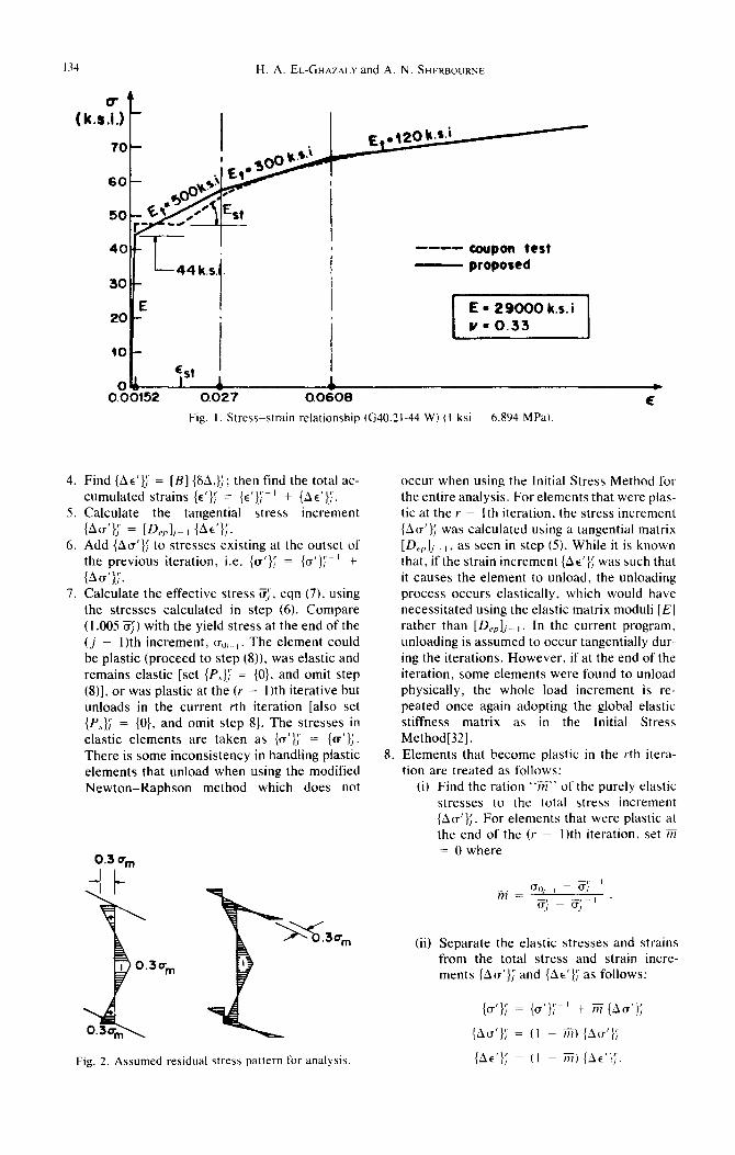
Fig. I. Stress-strain relationship (G40.21-44 W) (I ksi = 6.804 MPa).
Find {AE’}; = [B] {SAi};; then find the total ac- cumulated strains {E’}: = {E’}:-’ + {AE’};. Calculate the tangential stress increment
IAo’); = ]D,,]~-I {AE’);. Add {Au’); to stresses existing at the outset of the previous iteration, i.e. {a’}; = {a’};‘-’ + {Au’};. Calculate the effective stress ;T;, eqn (7), using the stresses calculated in step (6). Compare (1.005 ?Yj) with the yield stress at the end of the (j - I)th increment, uO, , . The element could be plastic (proceed to step (8)), was elastic and remains elastic [set {P,); = {0}, and omit step (8)], or was plastic at the (r - I)th iterative but unloads in the current rth iteration [also set {P,,,); = {0}, and omit step 81. The stresses in elastic elements are taken as {a’};’ = {a’};. There is some inconsistency in handling plastic elements that unload when using the modified Newton-Raphson method which does not
Fig. 2. Assumed residual stress pattern for analysis.
8.
occur when using the Initial Stress Method for the entire analysis. For elements that were plas- tic at the Y - lth iteration, the stress increment {Au’}; was calculated using a tangential matrix [D,,j]i_I, as seen in step (5). While it is known that, if the strain increment {Ae’}; was such that it causes the element to unload, the unloading process occurs elastically, which would have necessitated using the elastic matrix moduli [E] rather than [D,],j_ , . In the current program, unloading is assumed to occur tangentially dur- ing the iterations. However, if at the end of the iteration, some elements were found to unload physically, the whole load increment is re- peated once again adopting the global elastic stiffness matrix as in the Initial Stress Method[32]. Elements that become plastic in the rth itera- tion are treated as follows:
(i) Find the ration “X’ of the purely elastic stresses to the total stress increment {Au’};. For elements that were plastic at the end of the (,’ - I)th iteration, set 7ti = 0 where
m = go, I - a; ’ cr;_c;-’
(ii) Separate the elastic stresses and strains from the total stress and strain incre- ments {Au’); and {he’); as follows:
{u’l; = {a’};+ ’ + m {Au’};
{Au’}; = (I - ?ii) {Au’};
{he’}; = (I - r?l) (AE’};.
Deformation theory for elastic-plastic buckling analysis of plates 135
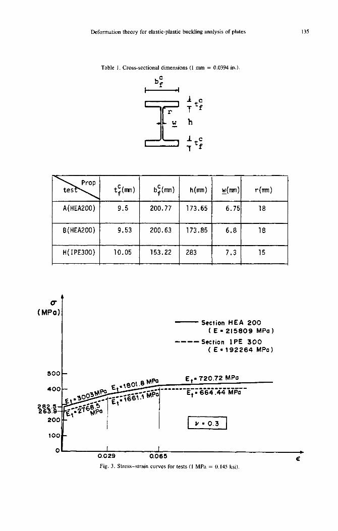
Table 1. Cross-sectional dimensions (1 mm = 0.0394 in.).
It= 7 f
A(HEA200) 9.5 200.77 173.65 6.75 18
B(HEA200) 9.53 200.63 173.85 6.8 18
H(IPE300) 10.05 153.22 283 7.3 15
28 5, 26 .9, 3
20(
- Section HEA 200 (E= 215809 MPa)
---- Section IPE 300 ( E = 192264 MPa)
1 umo.3 1
I I 0.029 0.065
Fig. 3. Stress-strain curves for tests (1 MPa = 0.145 ksi).
H. A. EL-GHAZALY and A. N. SHERBOURNE
0 2 3 4 8
(mm 1
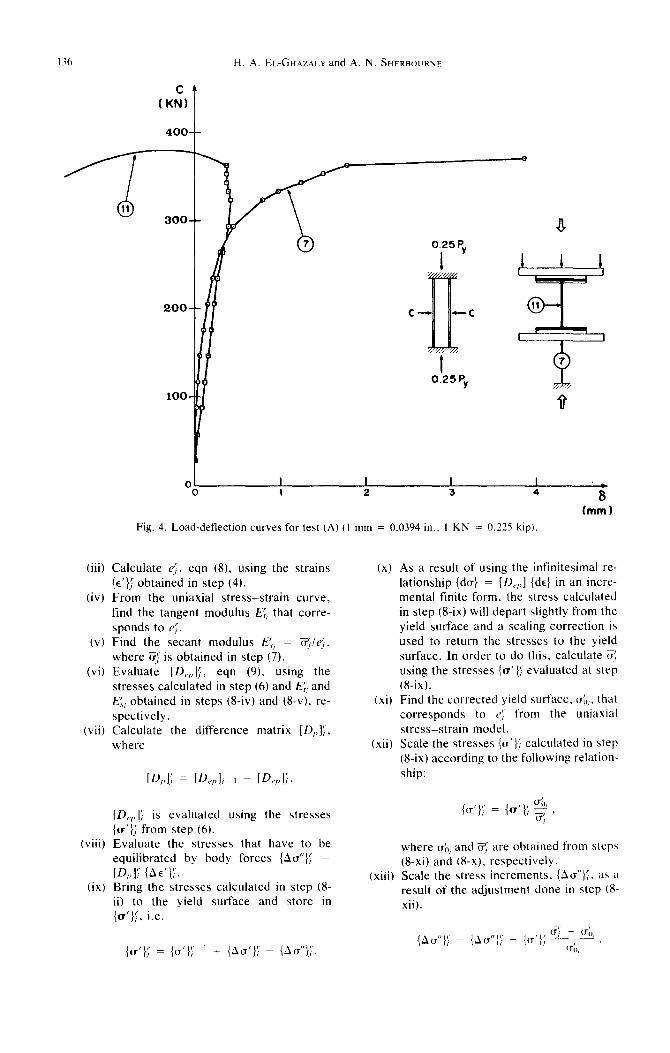
Fig. 4. Load-deflection curves for test (A) (I mm = 0.0394 in.. I KN = 0.225 kip).
(iii)
(iv)
(v)
(vi)
(vii)
(viii)
(ix)
Calculate e;, eqn (8), using the strains {E’); obtained in step (4). From the uniaxial stress-strain curve, find the tangent modulus EF, that corre- sponds to e;‘. Find the secant modulus i?,, = ??;le;, where $ is obtained in step (7). Evaluate [D,,,,],;, eqn (9), using the stresses calculated in step (6) and E;, and E”, obtained in steps @-iv) and (8-v). re- spectively. Calculate the difference matrix ID,,]:, where
[D,,,,],; is evaluated using the stresses {a’}; from step (6). Evaluate the stresses that have to be equilibrated by body forces {Au”}:’ = IQ>l,; {he’);. Bring the stresses calculated in step (8- ii) to the yield surface and store in {a’}:‘, i.e.
(x)
(xi)
(xii)
(xiii)
As a result of using the infinitesimal re- lationship {dcr} = [D,,,,] {de} in an incre- mental finite form, the stress calculated in step @-ix) will depart slightly from the yield surface and a scaling correction is used to return the stresses to the yield surface. In order to do this, calculate (r: using the stresses {a’}: evaluated at step (a-ix). Find the corrected yield surface. CJ;,,. that corresponds to 1~: from the uniaxial stress-strain model. Scale the stresses {u’); calculated in step (S-ix) according to the following relation- ship:
(CT’}; = {a’}; 2 I
where I$,, and 5; are obtained from steps @-xi) and (8-x). respectively. Scale the stress increments, (Au”}:, as a result of the adjustment done in step (X- xii).
(a’); = {u’); ’ + (Au’}; - {ilu”}:.

Deformation theory for elastic-plastic buckling analysis of plates 137
I C m,,(exp) 1370.4 KN
Cc, (onalyticOl) 0378. KN I
I P=O.25Py
a plastic zones buckling imminan?
-.Lc
/ buckling mode opposite force ‘C’
Fig. 5. Analysis of column A (I KN = 0.225 kip).
(xiv) Compute the nodal forces corresponding to the equilibrating body stresses ob- tained in step (g-xiii). For the (ith) ele- IO. ment, these forces are given by:
{6Ri)r = J”, [B]r {AU”}: dV,.. Il.
9. Assemble the structural global unbalanced load vector {SR}J where
NE
{6R}J = 2 {SRi}J, i= I
where (NE) is the total number of membrane elements. Find {SAli” by solving the equation
[K$ , {&A};+ ’ = (6R):‘.
Repeat steps (3) through (IO) until the following criterion is satisfied
The value of l l can be taken as any desired small value, depending upon the imposed level of accuracy.
H. A. EL.-GHA~AL.Y and A
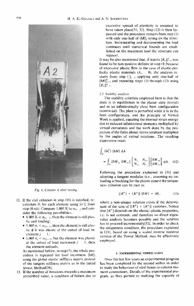
Fig. 6. Column A after testing
12. If the exit criterion in step (I I) is satisfied, re- calculate Si for each element using {n’}; from step (g-xii). Compare I.005 cr/ to o,,, , and con- sider the following possibilities: l I .005 E, 2 o,,, , . then the element is still plas-
tic and loading; l I .005 a/ < ur,, , , then the element is still elas-
tic if it was elastic at the outset of load in- crementj - I:
l I .005 a, < (T,),_, , but the element was plastic at the outset of load increment j - I; then the element unloads.
13. If the number of iterations exceeds a maximum
As mentioned before, in step (7). the whole pro- cedure is repeated for load increment {SR}, using the global elastic stiffness matrix instead of the tangent stiffness matrix as in the Initial Stress Method[281.
N. SHERBOURNE
excessive spread of plasticity is assumed to have taken place[3 I, 321. Step (I 2) is then by- passed and the procedure restarts from step (1) with only one-half of {6R}j acting on the struc- ture. Incrementing and decrementing the load continues until numerical bounds are estab- lished on the maximum load the structure can support.
It may be also mentioned that, if matrix [K,r!, was found to be non-positive definite in step (I) because of excessive plastic flow in the case of elastic-per- fectly plastic materials (E, = 0), the analysis re- starts from step { ),_Z applying only one-half of (U?}~~_, and repeating steps (I) through (13) using [K,]$'i ?.
The stability criterion employed here is that the plate is in equilibrium in the planar state (trivial) and in an infinitesimally close bent configuration (nontrivial). The plate is perturbed while it is in the bent configuration, and the principle of Virtual Work is applied, equating the internal strain energy due to induced infinitesimal moments multiplied by virtual curvatures and the work done by the pro- jection of the finite planar stress resultant multiplied by the angles of virtual rotations. The resulting expression reads
I il {SC} {6M} dA
Following the procedure explained in (311 and adopting a tangent modulus (i.e., assuming no un- loading at buckling for the plastic zones) the unique- ness criterion can be cast as
{IK"] + II {SW = {O}, (13)
where a non-unique solution exists if the determi- nant of the sum of {[Kh] + [K'I} vanishes. Notice that [ Kh] depends on the elastic-plastic properties, i.e. is not constant. and therefore no direct eigen- value analysis becomes possible and the solution has to proceed incrementally[32]. In order to check the uniqueness condition, the procedure explained in (331, based on using a scaled inverse iterative version of the Power Method, may be effectively employed.
4. EXPERIMENTAL VERIFICATION
Over the last few years an experimental program has been completed by the second author in order to study the behaviour of steel beam-to-column mo- ment connections. Details of the experimental pro-
prescribed value, a condition of failure due to gram. as they pertain to studying the capacity ot
Deformation theory for elastic-plastic buckling analysis of plates 139
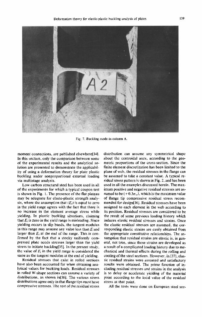
Fig. 7. Buckling mode in column A.
moment connections, are published elsewheret341. In this section, only the comparison between some of the experimental results and the analytical so- lution are presented to demonstrate the applicabil- ity of using a deformation theory for plate plastic buckling under nonproportional external loading via multistage analysis.
Low carbon structural steel has been used in all of the experiments for which a typical coupon test is shown in Fig. 1. The presence of the flat plateau may be adequate for elasto-plastic strength analy- sis, where the assumption that (E,) is equal to zero in the yield range agrees with the fact that there is no increase in the element average stress while yielding. In plastic buckling situations, claiming that E, is zero in the yield range is misleading. Since yielding occurs in slip bands, the tangent modulus in this range may assume any value less than E and larger than E, at the end of the range. This is con- firmed by the fact that a stocky uniformly com- pressed plate needs stresses larger than the yield stress to initiate buckling[35]. In the present study, the value of Et in the yield range is considered the same as the tangent modulus at the end of yielding.
Residual stresses that exist in rolled sections have also been accounted for when obtaining ana- lytical values for buckling loads. Residual stresses in rolled W-shape sections can assume a variety of distributions, as shown in[361. The various stress distributions agree only in that flange tips must have compressive stresses. The rest of the residual stress
distribution can assume any symmetrical shape about the centroidal axes, according to the geo- metric proportions of the cross-section. Since the finite element discretization has been limited to the plane of web, the residual stresses in the flange can be assumed to take a constant value. A typical re- sidual stress pattern is shown in Fig. 2, and has been used in all the examples discussed herein. The max- imum positive and negative residual stresses are as- sumed to be (k O.~U,,~), which is the maximum value of flange tip compressive residual stress recom- mended for design[361. Residual stresses have been assigned to each element in the web according to its position. Residual stresses are considered to be the result of some previous loading history which induces elastic residual stresses and strains. Once the elastic residual stresses are assumed, the cor- responding elastic strains are easily obtained from the appropriate constitutive relationships. The as- sumption that residual strains are elastic is, in gen- eral, not true, since these strains are developed as a result of a complicated loading history due to me- chanical and thermal effects during the rolling and cooling of the steel sections. However, in 1371, elas- tic residual strains were assumed and satisfactory results were obtained. The prime function of in- cluding residual stresses and strains in the analysis is to delay or accelerate yielding of the material point according to the local value of the residual stress at that point.
All the tests were done on European steel sec-
H. A. El..-GHAZALY and A. N. SHERBOURNE
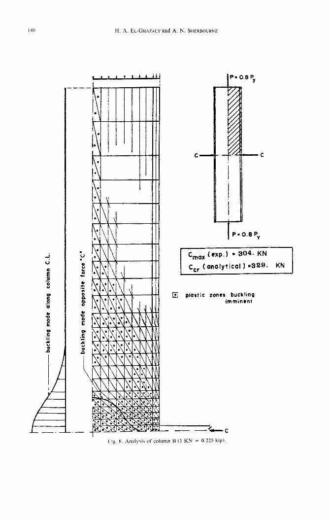
a plastic zones buckting imminent
t.~y. X. Analysis of column H (1 KN = 0.225 kip).
Deformation theory for elastic-plastic buckling analysis of plates 141
tions (HEA200) and (IPE300) for which the average section dimensions are shown in Table 1. The av- erage coupon test results for the two sections were not identical, especially the value of the yield stress, and Fig. 3 shows the trilinear stress-strain uniaxial relationship used in the analysis.
4.1 Test A The column (HEA200) was first subjected to
axial uniform stress of (0.250,~); then two equal and opposite horizontal forces (C) at the mid-height of the column were increased until the column web failed by buckling. During the application of the horizontal forces, the axial load was kept constant. The external loading is nonproportional, as evi- denced by the previous discussion. Figure 4 rep- resents a plot of the applied horizontal force (c) and readings of two dial gauges installed to measure the in-plane deformations (dial gauge 7) and the out-of- plane deflections (dial gauge 11). It may be noticed that nonlinearity due to plasticity is significant, as shown by the readings of dial gauge 7. Dial gauge I1 is primarily used to indicate the occurrence of buckling. The web plate buckles at C,, equal to (362.6 kN), while the analytical solution using mul- tistage analysis and deformation theory predicted buckling at C,, equal to (378 kN), which slightly overestimated the maximum load observed exper- imentally by about 2.1%. Due to the double sym- metry of the problem, only one quadrant of the col- umn needs to be considered in the analysis. The in- plane boundary conditions are imposed along the axes of symmetry such that the displacement nor- mal to each axis is set equal to zero. The buckling boundary conditions are prescribed such that the column is assumed to be totally fixed at the two ends (W = w,., = w,,, = 0), while (w,,) and (IV,,,) were set equal to zero along the (I’) and (X) axes, Fig. 11, respectively. The lateral displacement, (w), at the point of application of the beam force, has also been suppressed. Figure 5 shows the finite ele- ment discretization, the plastic zones at incipient buckling, and the resulting buckling mode. In the experiments, the column specimens were covered with whitewash, which flaked off at yielding, to give a description of the plastic zones at various stages of loading. The photo in Fig. 6 shows the column (A) after testing; the dark areas represent plastic zones. Comparison of the predictions of the ana- lytical solution with the plasticity shown in the pic- ture may not be satisfactory, since more flaking oc- curs due to flexure once the web starts to buckle and the photograph is taken after excessive post- buckling. However, a general similarity between the figures may be observed. The buckling mode consists of one major buckle in the transverse and longitudinal directions which peaks at the column center, as shown in Fig. 5. This agrees completely with the buckling mode observed experimentally, Fig. 7.
4.2 Test B
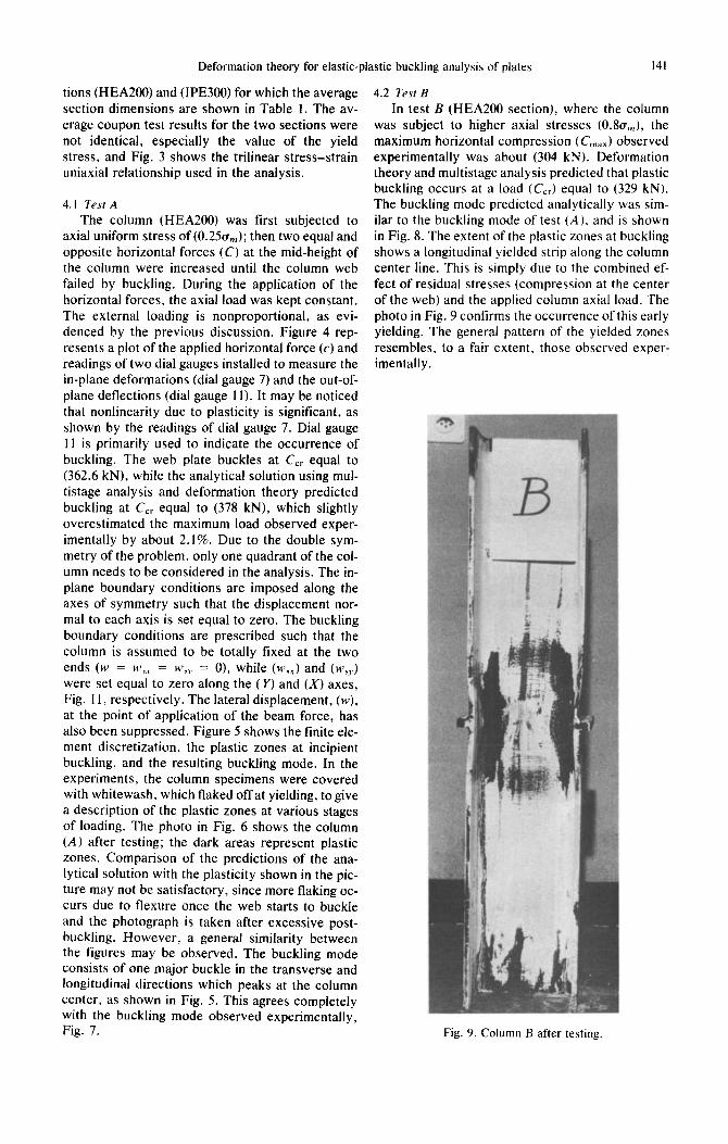
In test B (HEA section), where the column was subject to higher axial stresses (O.~U,,,), the maximum horizontal compression (C,,,) observed experimentally was about (304 kN). Deformation theory and multistage analysis predicted that plastic buckling occurs at a load (C,,) equal to (329 kN). The buckling mode predicted analytically was sim- ilar to the buckling mode of test (A), and is shown in Fig. 8. The extent of the plastic zones at buckling shows a longitudinal yielded strip along the column center line. This is simply due to the combined ef- fect of residual stresses (compression at the center of the web) and the applied column axial load. The photo in Fig. 9 confirms the occurrence of this early yielding. The general pattern of the yielded zones resembles, to a fair extent, those observed exper- imentally.
Fig. 9. Column B after testing.
142
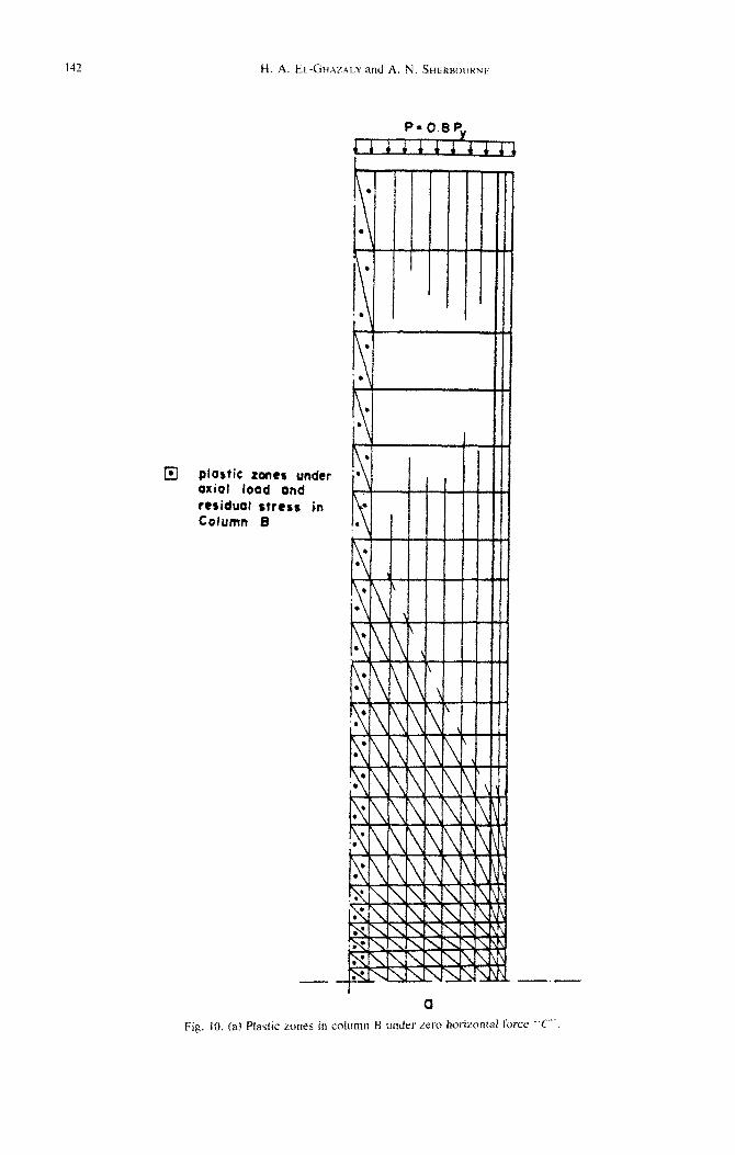
El plastic rontr undtr Oxiol load and residual stttss in Cotumn 8
Deformation theory for elastic-plastic buckling analysis of plates 143
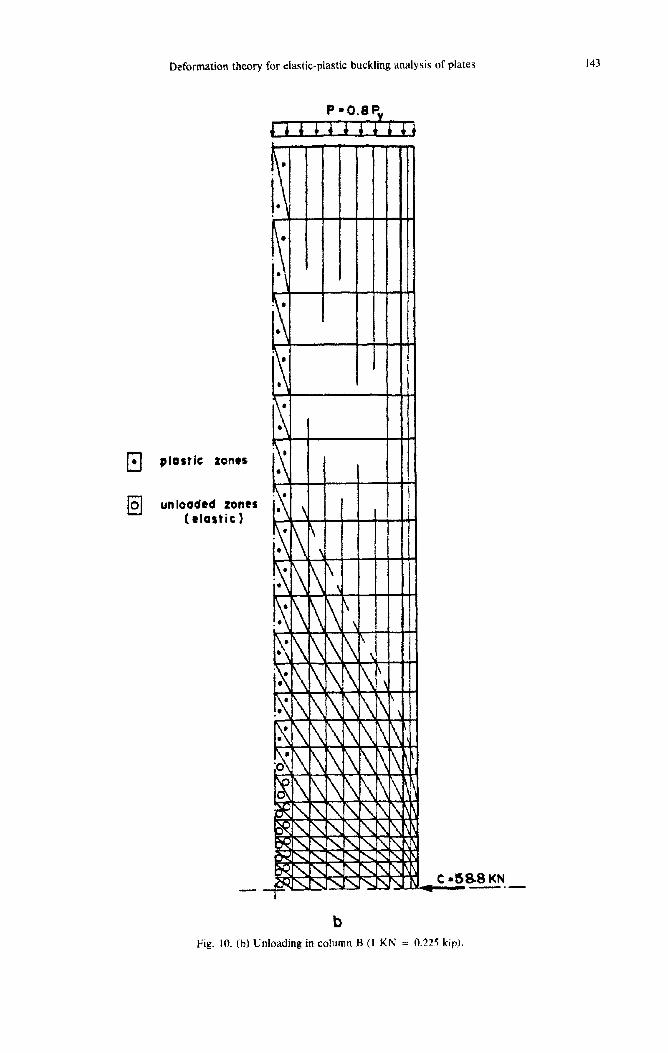
cl * p tortic zoner
cl 0 unloaded tones t elastic I
Fig. 10. (b) Unloading in column B (I KN = 0.225 kip).
144
Cl .
0 X
plastic zones
zones that reloodtd
. Ii
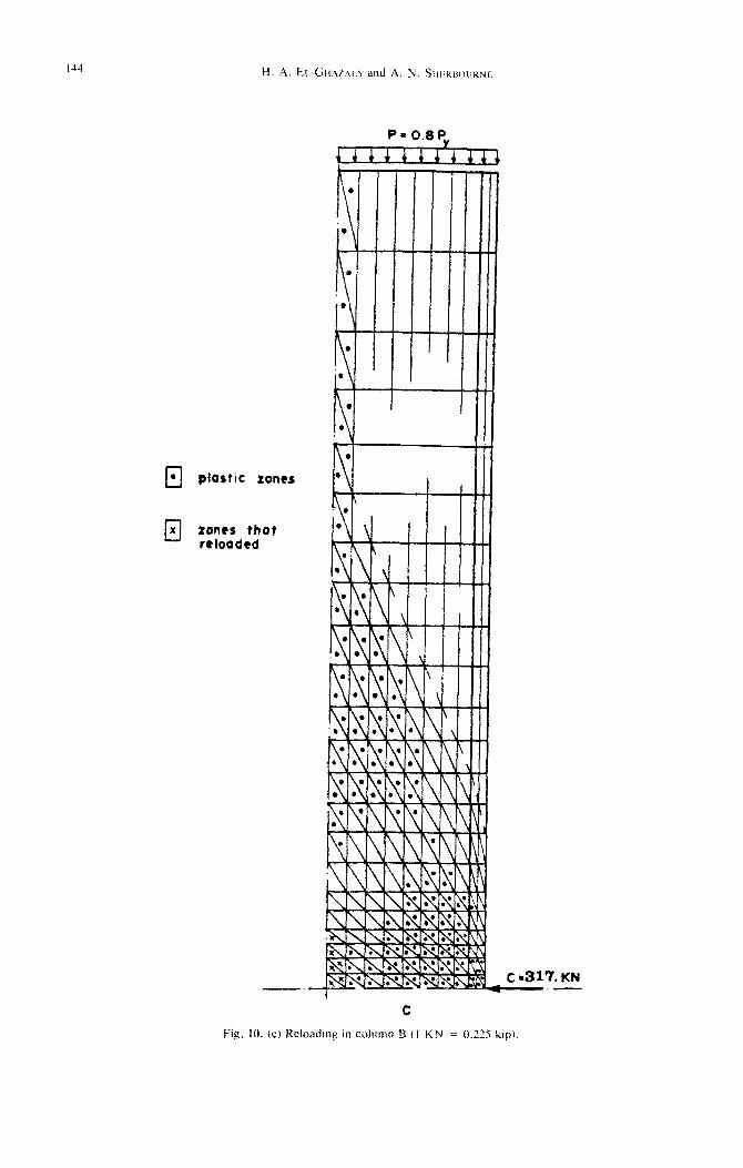
Fig. IO. (c) Reloading in column B I I KN = 0.23 kip).

Deformation theory for elastic-plastic buckling analysis of plates 145
w=o L
woo J, u=o -4 w,x=o I 3 =_
c, t-T L w = W,% = w, y =o Lv=O
Planar Boundary Conditions
Bending Boundory Conditions
Fig. I I. Boundary conditions for the analysis of column H.
Figure 10 demonstrates the capability of the ana- lytical procedure to handle loading-unloading and reloading in the various elements, using a defor- mation theory. Early yielding occurs near the col- umn center line as a result of the combined effects of the compressive axial loads and the assumed compressive residual stress there, Fig. 10(a). As the horizontal compressive force (C) is applied, a com- plementary tension field is created in the vertical direction (Poisson’s effect) causing unloading of some of the previously yielded elements along the column center line, Fig. 10(b). As more horizontal load (C) is applied, the increasing compressive stresses in the X direction cause some of the un- loaded elements to reload again, as seen in Fig. IO(c). The plastic zones at buckling are shown in Fig. 8.
4.3 Test H
In the test, the column (IPE300) was initially subjected to vertical uniform axial stresses equal to (0.80,,). A couple subsequently applied to each flange, created by two equal and opposite forces (C
and T), was increased until the web plate failed by buckling. The in-plane boundary conditions are se- lected such that the (u) displacement along the col-
umn center line is set equal to zero because of sym- metry about this axis, shown in Fig. 11. Also, rollers are provided at the column base to prevent rigid body vertical movement. The buckling bound- ary conditions are assumed by considering the col- umn to be fixed at its two ends (W = w,, = w,,. = 0). Along the Y-axis, (w,,~) is imposed as zero, in- dicating a symmetrical buckling mode about this axis. Moreover, the out-of-plane deflection at the point of application of (C) and (T) is set equal to zero. This column reached its maximum capacity
Table 2. Results obtained using the flow and the deformation theories for columns A and H (I KN =
0.225 kip).
146 H. A. EL-GHAZ4l.Y al
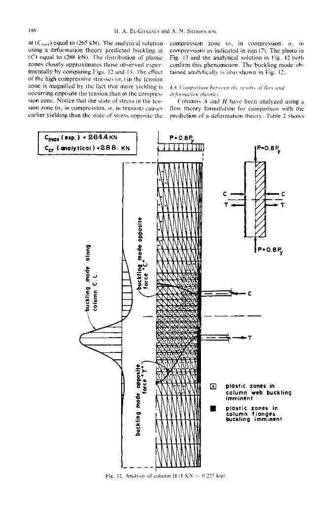
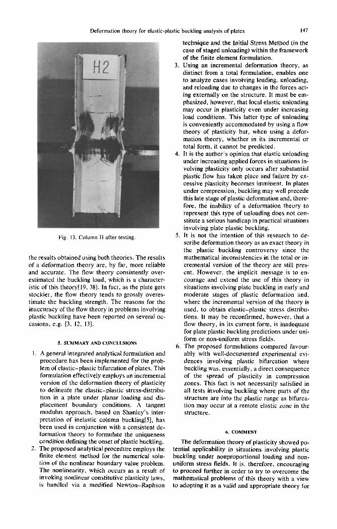
at (C,,;,,) equal to (265 kN). The analytical solution using a deformation theory predicted buckling at (C) equal to (288 kN). The distribution of plastic zones closely approximates those observed exper- imentally by comparing Figs. 12 and 13. The effect
of the high compressive stresses (CT,.) in the tension zone is magnified by the fact that more yielding is occurring opposite the tension than in the compres- sion zone. Notice that the state of stress in the tcn- sion zone (CT,. in compression. o, in tension) causes earlier yielding than the state of stress opposite the
nd A. N. SIIFRHOLIRNL
compression zone ((7, in compression. o, in compression) as indicated in eqn (7). The photo in Fig. 13 and the analytical solution in Fig. 12 both
confirm this phenomenon. The buckling mode ob-
tained analytically is also shown in Fig. 12.
Columns A and H have been analyzed using a flow theory formulation for comparison with the prediction of a deformation theory. Table 2 shows
q plastic zones in column web buck imminent
n plastic zones in column f longer buckling imminen
;ling
t
Fig. 13,. Analysis of column H (I KN = 0.225 kipl
Deformation theory for elastic-plastic buckling analysis of plates 147
Fig. 13. Column H after testing.
the results obtained using both theories. The results of a deformation theory are, by far, more reliable and accurate. The flow theory consistently over- estimated the buckling load, which is a character- istic of this theory[l9, 381. In fact, as the plate gets stockier, the flow theory tends to grossly overes- timate the buckling strength. The reasons for the inaccuracy of the flow theory in problems involving plastic buckling have been reported on several oc- casions, e.g. [3, 12, 131.
5. SUMMARY AND CONCLUSIONS
I. A general integrated analytical formulation and procedure has been implemented for the prob- lem of elastic-plastic bifurcation of plates. This formulation effectively employs an incremental version of the deformation theory of plasticity to delineate the elastic-plastic stress-distribu- tion in a plate under planar loading and dis- placement boundary conditions. A tangent modulus approach, based on Shanley’s inter- pretation of inelastic column buckling[5], has been used in conjunction with a consistent de- formation theory to formulate the uniqueness condition defining the onset of plastic buckling.
2. The proposed analytical procedure employs the finite element method for the numerical solu- tion of the nonlinear boundary value problem. The nonlinearity, which occurs as a result of invoking nonlinear constitutive plasticity laws, is handled via a modified Newton-Raphson
3.
4.
5.
6.
technique and the Initial Stress Method (in the case of staged unloading) within the framework of the finite element formulation. Using an incremental deformation theory, as distinct from a total formulation, enables one to analyze cases involving loading, unloading, and reloading due to changes in the forces act- ing externally on the structure. It must be em- phasized, however, that local elastic unloading may occur in plasticity even under increasing load conditions. This latter type of unloading is conveniently accommodated by using a flow theory of plasticity but, when using a defor- mation theory, whether in its incremental or total form, it cannot be predicted. It is the author’s opinion that elastic unloading under increasing applied forces in situations in- volving plasticity only occurs after substantial plastic flow has taken place and failure by ex- cessive plasticity becomes imminent. In plates under compression, buckling may well precede this late stage of plastic deformation and, there- fore, the inability of a deformation theory to represent this type of unloading does not con- stitute a serious handicap in practical situations involving plate plastic buckling. It is not the intention of this research to de- scribe deformation theory as an exact theory in the plastic buckling controversy since the mathematical inconsistencies in the total or in- cremental version of the theory are still pres- ent. However, the implicit message is to en- courage and extend the use of this theory in situations involving plate buckling in early and moderate stages of plastic deformation and, where the incremental version of the theory is used, to obtain elastic-plastic stress distribu- tions. It may be reconfirmed, however, that a flow theory, in its current form, is inadequate for plate plastic buckling predictions under uni- form or non-uniform stress fields. The proposed formulations compared favour- ably with well-documented experimental evi- dences involving plastic bifurcation where buckling was, essentially, a direct consequence of the spread of plasticity in compression zones. This fact is not necessarily satisfied in all tests involving buckling where parts of the structure are into the plastic range as bifurca- tion may occur at a remote elastic zone in the structure.
6. COMMENT
The deformation theory of plasticity showed po- tential applicability in situations involving plastic buckling under nonproportional loading and non- uniform stress fields. It is, therefore, encouraging to proceed further in order to try to overcome the mathematical problems of this theory with a view to adopting it as a valid and appropriate theory for
14x H. A. EL-GHAZALY and A N. SHEKBOURNE
plastic buckling. If the presence of a vertex in the yield surface is necessary to legitimize the theory of nonproportional loading[(i] from a mathematical point of view, it may be worthwhile to employ an-
other yield surface, such as a Tresca surface, which already has sharp corners. Another approach may be to adopt a piecewise linear von Mises yield sur- face which would serve the same purpose. It is known that employing a P.W.L. yield surface re-
sults in appreciable simplifications when approach- ing elasto-plastic analysis via mathematical pro- gramming[30]. Similar improvements may also result in the convergence of the iterative tech- niques, such as the modified Newton-Raphson method. However, it should be mentioned, in this regard, that the convergence characteristics of the modified Newton-Raphson technique, when used
in conjunction with the incremental version of the deformation theory and employing the continuous von Mises surface, were consistent and may be rated as excellent.
Efforts towards improving the results of a flow theory in plastic buckling situations through mod- ifying the tangent shear modulus must continue, as there is evidenceI31, 391 to suggest that the current impractical results of this theory are attributable mainly to errors in assessing this material property.
Ackno~ledgmenrs-The authors are grateful to Professor R. N. Dubey for his contribution to an understanding of plastic bifurcation and to the NSERC for assistance re- ceived which made possible the computational work pre- sented in this study.
REFERENCES
I. G. H. Handelman and W. Prager, Plastic buckling of rectangular plates under edge thrusts. Tech. Note- 1530, NASA (1948).
2. P. P. Bijlaard, Theory and tests on the plastic stability of plates and shells. J. Aero. Sci. 16, 529-541 (1949).
3. F. R. Shanley, Inelastic column theory. J. Aero. Sci. 14, 261-268 (1947).
4. E. Z. Stowell, A unified theory of plastic buckling of columns and plates. Tech. Note-1556, NASA (1948).
5. F. R. Shanley, The column paradox. J. Arro. Sci. 13, 678 (1946).
6. B. Budiansky, A reassessment of deformation theo- ries of plasticity. J. Appl. Mech. 26, 259-264 (1959).
7. D. C. Drucker, A more fundamental approach to plas- tic stress-strain relations. Proc. First U.S. Nutionul Congress of Applied Mcchanic,.s, ASME, 487-491
8. M. J. Sewell, A general theory of elastic and inelastic plate failure-H. J. Mech. Phys. Solids 12, 279-297 (1964).
9.
IO.
11.
12.
13.
M. J. Sewell, A plastic flow rule at a yield vertex. 1. Mech. Phys. Solids 22, 469-490 (1974). R. N. Dubey and N. C. Lind, Reassessment of the incremental elastic-plastic constitutive relation Mech. Res. Comm. 3, 41 l-415 (1976). R. N. Dubey, Uniqueness criteria for elastic-plastic solids, Trans. CSME 4, 181-188 (1976-77). R. N. Dubey and M. J. Pindera, Effect of rotation of principal axes on effective shear modulus in elastic- plastic solids, J. Srrucr. Mech. 5, 77-85 (1977). R. N. Dubey, Bifurcation in elastic-plastic plates. 36. L. S. Beedle and L. Tall. Basic column strength. .1.
(1951). 32.
33.
34.
35.
14.
IS.
16.
17.
18.
19.
20.
21.
22.
23.
24.
25.
26.
27.
28.
29.
30.
31.
Solid Mech., Univ. of Waterloo. Ont.. Canada, Papet No. I56 (April 1979). E. T. Gnat and D. C. Drucker. Inelastic instability and incremental theories of plasticity. J. Aero. Sci. 20, 181-186 (1953). J. W. Hutchinson and B. Budiansky, Analytical and numerical study of the effects of initial imperfections on the inelastic buckling of a cruciform of column. Proc. IUTAM Symposilrm on buckling of structure.\. Harvard Univ., Cambridge, MA, 98-105 (1974). D. Bushnell, A strategy for the solution of problems involving large deflections. plasticity and creep. /fir. J. Numer. Merh. Engng 11, 683-708 r 1977). K. Bathe and S. Bolourchi, A geometric and material nonlinear plate and shell element. Comput. Struc,trrrr.\ 11, 23-48 (1980). M. A. Crisfield, Large-deflection elasto-plastic buck- ling analysis of plates using finite elements. TRRL Re- port LR 593 (1973). S. C. Shrivastava, Inelastic buckling of plates includ- ing shear effects. Int. J. So/ids Strwfures 15, 567-575 (1979). R. A. Pride and G. J. Heimeral, Plastic buckling of simply supported compressed plates. Tech. Note- 1817, NASA (1949). G. Isakson, H. Armen. Jr.. and A. Pifko, Discrete- element methods for the plastic analysis of structure\. CR-803, NASA (1967). E. L. Stanton and L. A. Schmit, A discrete element stress and displacement analysis of elasto-plastic plates. AIAA J. 8, 1245-1251 (1970). S. C. Tang. Elasto-plastic and large deformation anal- ysis of thrn shells by the deformation theory of plas- ticity. Comput. Strlrc.ture.\ 6, 297-303 (1976). A. Mendelson. Plusticity Theor\, and App/iurriorr.\. Macmillan, New York (1968). R. N. Dubey and S. T. Ariardtnam. Bifurcation in elastic-plastic solids in plane stress, Q. Appl. Mech. XXVII(3). 381-390 (19691. J. A. Yara. T. V. Galambos, and M. K. Ravindrd, The bending resistance of steel beams. J. Srruct. IX,.. ASCE 104, No. ST9 1355-1370 (Sept. 1978). 0. C. Zienkiewicz. The Finirc Elrmer~t Method irr I+- gineering Science. McGraw-Hill. New York (I971 1. 0. C. Zienkiewicz, S. Valliappan. and I. P. King. Elasto-plastic solutions of engineering problems “in- itial stress”. fmite element approach. Int. J. Nur,ler. Meth. Engng 1, 75-100 (1969). G. C. Nayak and 0. c‘. Zienkiewicz. Elasto-plastic stress analysis. A generalization for various consti- tutive relations including strain softening. Irr/. J. Nlcmer-. Meth. Engng 5, 113-135 (1972). 0. E. Grierson, A. Franchi, 0. Dedonato, and L. Cor- radi, Mathematical programming and nonlinear finite element analysis. Comprrr. Merh. Appl. Mrclr. Eugir,q 17118, 497-518 (1979). H. A. El-Ghazaly, Elastic-plastic bifurcation analysis of column webs in moment connections of steel struc- tures. Ph.D. thesis submitted at the University of Wa- terloo. Waterloo. Canada ( 1984). H. A. El-Ghazaly, R. N. Dubey. and A. N. Sher- bourne, Elasto-plastic buckling of stiffener plates in beam-to-column flange connections. Cornput. Srruv
turcs 18, 201-213 (1984). H. El-Ghazaly and A. N. Sherbourne, The power method in finite element analysis of plastic bifurcation plate problems. Solid Mechanics Division, University of Waterloo. Ontario. Canada. paper No. 176 (Jan. 1983). A. N. Sherbourne and H. A. El-Ghazaly. Steel beam to-column connections (in press). M. G. Lay, Yielding of uniformly loaded steel mem- bers. J. Siruct. Div., ASCE 91, No. ST6. Proc. Paper 4580. pp. 49-66 (Dec. 19651.

Deformation theory for elastic-plastic buckling analysis of plates 149
Slruct. Div., AXE 86, No. ST7, Proc. Paper 2555, buckling of short plate stiffeners in beam-column con- pp. 139-173 (July 1960). nections. Proc. Fourth Engineering Mechanics Divi-
37. J. L. Dawe and G. L. Kulak, Local buckling of W sion Speciality Conference, Purdue Univ., West La- shapes used as columns, beams and beam-columns. fayette, IN (May 1983). Structural Engineering Report No. 95, Dept. of Civil 39. H. A. El-Ghazaly, A. N. Sherbourne, and R. N. Engng. The University of Alberta, Edmonton, Al- Dubey, Inelastic interactive distorsional buckling of berta, Canada (March 1981). W-shape steel beams. Comput. Strucrures 19, 351-
38. H. A. El-Ghazaly and A. N. Sherbourne, Inelastic 368 (1984).