deformation prediction of aero-structural assembly
TRANSCRIPT

DEFORMATION PREDICTION OF AERO-STRUCTURAL ASSEMBLY INVOLVING DRILLING-INDUCED STRESSES
Hua Wang State Key Laboratory of Mechanical System and
Vibration, Shanghai Jiao Tong University Shanghai 200240, P.R. China
Qing Ge Shanghai Key Laboratory of Digital Manufacture for Thin-walled Structures, Shanghai Jiao Tong
University Shanghai 200240, P.R. China
ABSTRACT Drilling is a material removal process which introduces
the plastic deformation and stresses around the hole. When large amounts of drilling stresses are added up, there will be deformation in the aero-structural assembly. This work presents a deformation predicting method based on finite element analysis considering drilling stresses. A riveting equivalent unit is employed to simulate the riveting process in order to obtain a balance between accuracy and the computational efficiency in finite element analyzing. Drilling stresses are added up into the riveting process with additional temperature fields in ABAQUS. The assembly of the two riveted plates and the trailing edge were considered to illustrate effects of drilling stresses coupling. The simulation results had shown that drilling stresses had little influence on one riveting deformation. When so many drilling stresses and riveting effects were added up, there will be striking deformation in the aircraft's structure. The deformation predicting method outlined in this work will enhance the understanding of the compliant components deformation resulting from the drilling stresses, and help systematically improving the precision control efficiency in civil aircraft industry.
Keywords: Civil aircraft; Assembly; Riveting; Drilling Stresses INTRODUCTION
Riveting is the principal method used for fastening metallic parts in the assembly of aerospace components, and ribs and edges used in the civil aircraft horizontal stabilizer are joined using rivets. Riveting bulging is unavoidable but extremely undesirable in the aircraft industries because it creates an uneven surface in the skin [1]. A good riveting process should attempt to minimize bulging, with zero as an ideal value. As far as the aircraft's structure is concerned, there are hundreds and thousands of rivets. When so many rivets' bulging effects are added up, there will be deformation in the
aircraft's structure. Deformation of aircraft's structure during assembly has a significant effect on the aerodynamic performance of the aircraft.
Riveting, residual stresses, machining distortion and other stochastic variables result in ribs and edges’ distortion. Part-to-part assembly of these compliant components regularly cause difficulties associated with dimensional variations. There are thousands of rivets in the horizontal stabilizer. It is impossible to analyze every riveting position and riveting process in the horizontal stabilizer FEA (Finite Element Analysis) model. A riveting equivalent unit [2] is employed to analyze the deviation induced by different riveting sequences. Equivalent unit for riveting brings a good balance between accuracy and the computational efficiency in finite element analyzing. The riveting equivalent unit proposed by Wang [2] only concerns the pressure induced by the deformation of rivet shank during riveting, without considering the stresses around the riveting holes induced by drilling.
Drilling is a material removal process which introduces the plastic deformation and stresses around the hole. When large amounts of drilling stresses are added up, there will be deformation in the aero-structural assembly. Although drilling may appear to be a simple process, it is in fact deceptively complex. Holes quality can be reduced in drilling by a number of factors. Some of the primary factors in the drilling of aircraft fastener holes are the material and geometry of the bit, sharpness of the bit, the work piece material, and human factors [3]. It is a challenging and important problem in mechanical engineering to consider the drilling stresses during the course of assembly, especially in aircraft industry.
The paper focuses on the dimensional issues of riveting assembly for the horizontal stabilizer, especially considering the stresses induced by drilling. After discussing the most relevant literature, the horizontal stabilizer assembly process and its FEA model is described. The drilling stresses around the riveting holes are simulated by the temperature fields in
1 Copyright © 2014 by ASME
Proceedings of the ASME 2014 International Mechanical Engineering Congress and Exposition IMECE2014
November 14-20, 2014, Montreal, Quebec, Canada
IMECE2014-36948
ABAQUS. Riveting equivalent unit is employed in the horizontal stabilizer FEA model to predict the riveting deformations. It brings a good balance between accuracy and the computational efficiency in FEA analyzing. The simulation results have shown that the drilling stresses affect the riveting deformation and stresses apparently.
LITERATURE REVIEW
The civil aircraft horizontal stabilizer is assembled with ribs and edges through a variety of processes. The aircraft assembly precision control should consider the non-rigid behaviors of compliant parts, such as ribs and edges [4]. Saadat [4-6] studied the wing box dimensional variation took place at Airbus UK to quantify the actual deformation occurring while assembling the wing panels onto the structure. Sim [7] presented a method for predicting dimensional variation in the assembly processes of a wing-box structure. FEM and experimental tests were conducted on the rib structure based on the site measurement gathered from Airbus assembly factory. Wang [2, 8-10] studied the horizontal stabilizer assembly precision control, the proposed FE model provides a capability of predicting the overall deformation of the trailing edge resulting from the individual edge’s and rib's deformation after machining.
Most metallic parts used in aircraft are joined by riveting. Drilling is a vital process before riveting and the drilling will leave stresses near the holes. Great care is expended on drilling quality because they are subject to high stresses. Significant research has been conducted on drilling parameters to characterize the residual stress state resulting from the drilling process. Williams [11] found three identifiable zones at the drilling point, that is the main cutting edges, the secondary cutting edges at the chisel edge and an indentation zone about the drill center. Liu [3] studied the effect of holes quality on fatigue life of open hole. It showed that many drilling parameters have a significant influence on the stress distribution and finally on the fatigue endurance of the joint, such as drilling speed, feeding speed and friction coefficient etc. Many researches [12-15] have been conducted on the drilling process modeling. They mainly focused on the relationship of the thrust force, torque and power increase with the drilling speed.
Furthermore, Sun [16] pointed out the importance of initial residual stress on the deformation of aeronautic components. As the riveting process is frequently used in aerospace manufacture, the residual stress induced by former drilling should be considered rather than neglected. In order to examine the effect of drilling process on fastening holes, Pirtini [17] proposed a mathematical model based on the mechanics of drilling for the prediction of cutting forces. It also visualized and quantified the hole quality. Ralph [18] studied the fatigue performance of production-quality aircraft fastener holes, it was reported that machining marks play a greater role than residual stress in the fatigue life of production-quality holes. Pei [19] studied the effect of the drilling processes on the surface quality of fastening holes of 7075-aluminum alloy plate used in aircraft
structures. It reported the measuring results of the surface roughness, residual stress and micro hardness under different drilling parameters. Wu [20] conducted a series of drilling experiments for surface quality control, and provided the distribution of residual stresses around the hole after drilling.
ASSEMBLY OF HORIZONTAL STABILIZER
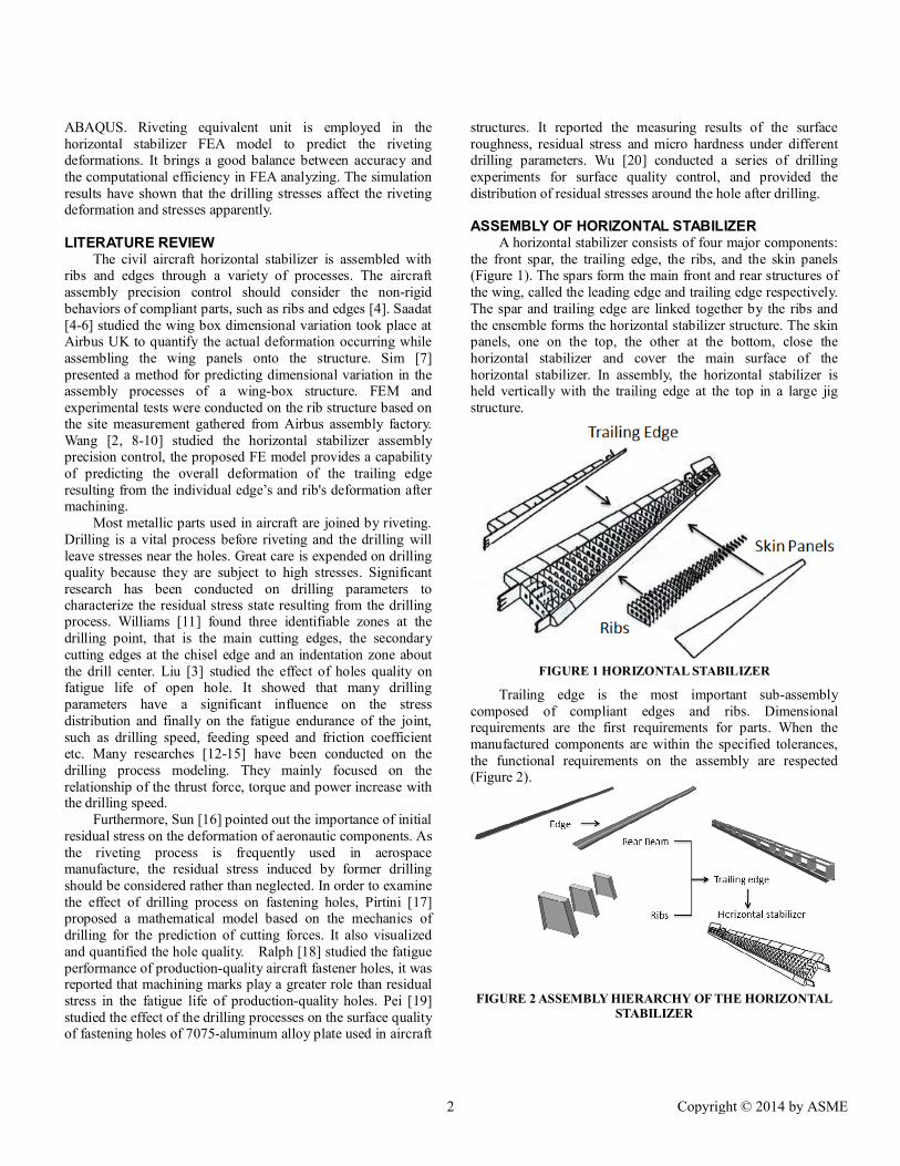
A horizontal stabilizer consists of four major components: the front spar, the trailing edge, the ribs, and the skin panels (Figure 1). The spars form the main front and rear structures of the wing, called the leading edge and trailing edge respectively. The spar and trailing edge are linked together by the ribs and the ensemble forms the horizontal stabilizer structure. The skin panels, one on the top, the other at the bottom, close the horizontal stabilizer and cover the main surface of the horizontal stabilizer. In assembly, the horizontal stabilizer is held vertically with the trailing edge at the top in a large jig structure.
FIGURE 1 HORIZONTAL STABILIZER
Trailing edge is the most important sub-assembly composed of compliant edges and ribs. Dimensional requirements are the first requirements for parts. When the manufactured components are within the specified tolerances, the functional requirements on the assembly are respected (Figure 2).
FIGURE 2 ASSEMBLY HIERARCHY OF THE HORIZONTAL
STABILIZER
2 Copyright © 2014 by ASME

In order to produce an acceptable representation of the assembly process, a 3D FE model is proposed. The FE model is created using commercial software ABAQUS CAE as the pre-processor. A FEA is carried out using the general-purpose FEA package ABAQUS Explicit. The typical experimental trailing edge structure has a total of 4 edges and 3 ribs, which are 7 series Al-alloy. They were meshed with 8-node, 3D solid, reduced integration C3D8R continuum three-dimensional brick elements. This resulted in 40,815 nodes and 20,200 elements approximately (Figure 3).
FIGURE 3 FE MODEL OF THE TRAILING EDGE
Ribs and edges used in the civil aircraft horizontal stabilizer are joined using rivets. Many riveting parameters have a significant influence on the stress distribution and finally on the fatigue endurance of the joint, such as squeeze force, clearance between rivet shank and hole, clamping angle, rivet length and friction coefficient etc. The dimensional deformation of the couple of plates after riveting is the key point of riveting modeling.
Modeling of one riveting process is complex and needs a large amount of computation. There are hundreds of rivets in the horizontal stabilizer. It is impossible to analyze every riveting position and riveting process in the horizontal stabilizer FEA model. Riveting equivalent unit is employed to maintain a good balance between accuracy and the computational efficiency [2]. Riveting equivalent unit is composed with two parts. One part is the pressure in the inner riveting holes calculated with equation (1). p = σ 1.5 + = σ (1.5+ ) (1)
where σ is the yield limit of the rivet material, D is the diameter of the riveted head, b is the rivet head width, d is the diameter of the rivet shank, and h is the height of the riveted head. The other is the analog connection of the riveting. MPC Beam rigid connection in ABAQUS is applied to the two riveted parts as illustrated in Figure 4.
FIGURE 4 SCHEMATIC OF MPC BEAM OF THE
RIVETING EQUIVALENT UNIT
SIMULATION OF DRILLING STRESSES Drilling is a vital process before riveting and it will leave
stresses near the holes. Although drilling may appear to be a simple process, it is in fact deceptively complex. Holes quality can be reduced in drilling by a number of factors. Some of the primary factors in the drilling of aircraft fastener holes are the material and geometry of the bit, sharpness of the bit, the work piece material, and human factors [3].
The FE model of drilling induced stresses is created using commercial software ABAQUS CAE as the pre-processor, as shown in Figure 5. The drilling-for-riveting structure has one rivet and two plates, which are 7 series Al-alloy. They are meshed using 8-node, 3D solid, reduced integration C3D8R continuum three-dimensional brick elements. It resulted in 50,250 nodes and 38,904 elements approximately.
FIGURE 5 THE FE MODEL OF THE DRILLING-HOLE
AND RIVETING PLATES
In order to understand the drilling stresses around the drilling-hole, experimental works were carried out under one-step-compound cutting (Winslow) condition [19]. The parameters are presented in Table 1. And the drilling stresses around the hole are shown in Figure 6.
TABLE 1 THE ONE-STEP-COMPOUND DRILLING METHOD AND PARAMETERS
Diameter (mm) 6.1
Turning speed (r•min-1) 3600
Feed rate (mm•r-1) 0.05
Cutting speed (m•min-1) 88.2
Coolant T80-92B
3 Copyright © 2014 by ASME
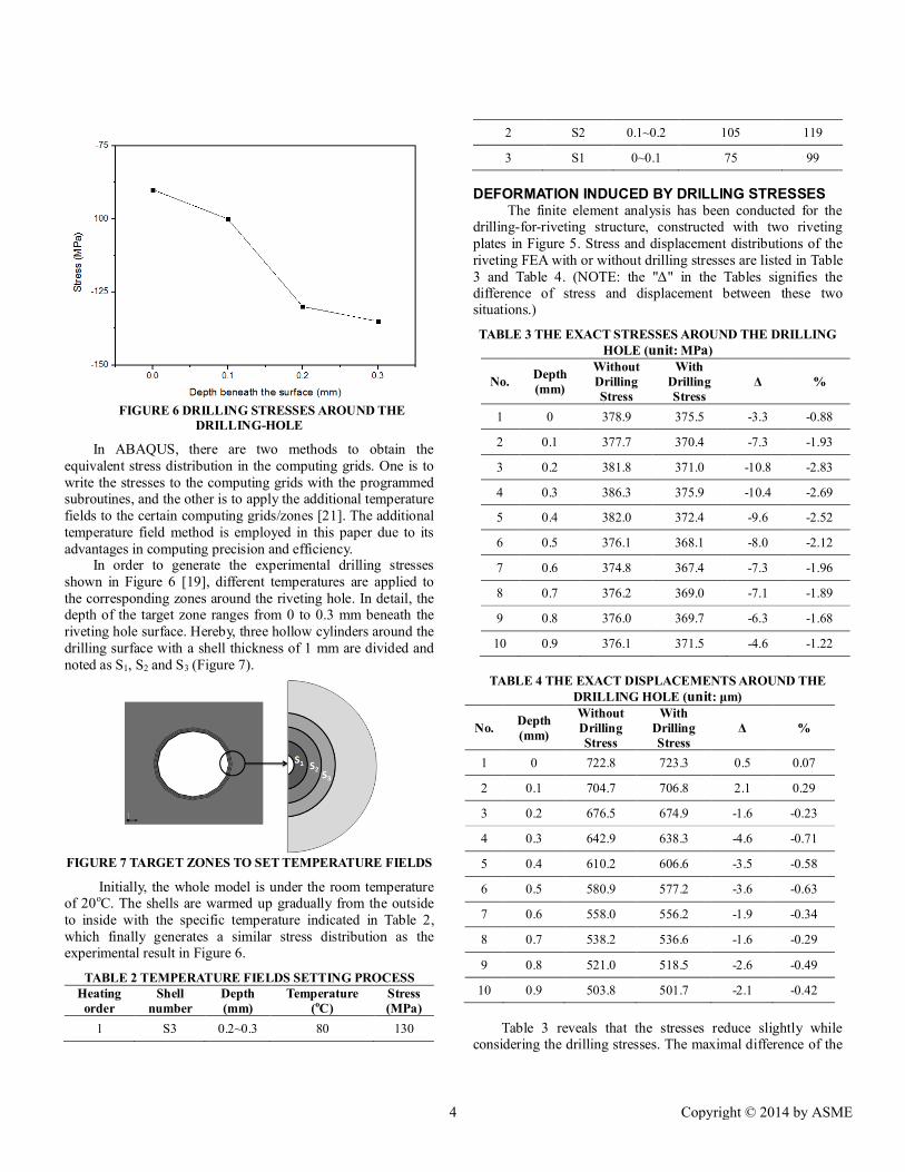
FIGURE 6 DRILLING STRESSES AROUND THE
DRILLING-HOLE
In ABAQUS, there are two methods to obtain the equivalent stress distribution in the computing grids. One is to write the stresses to the computing grids with the programmed subroutines, and the other is to apply the additional temperature fields to the certain computing grids/zones [21]. The additional temperature field method is employed in this paper due to its advantages in computing precision and efficiency.
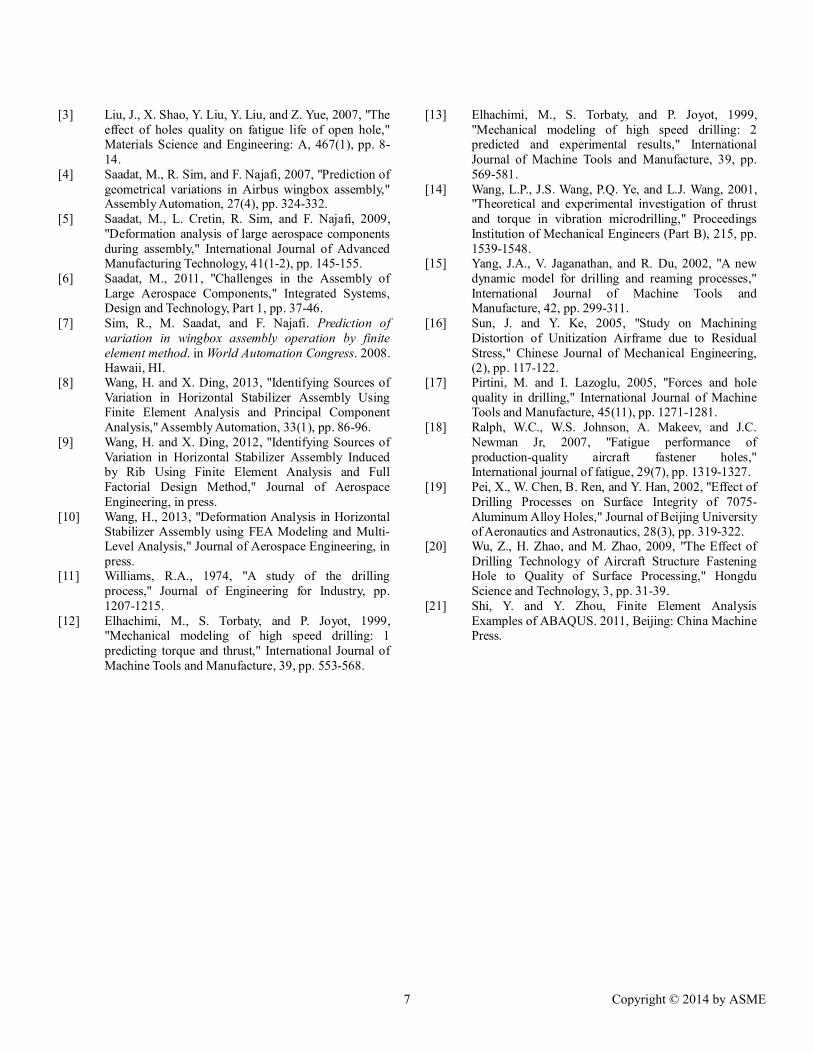
In order to generate the experimental drilling stresses shown in Figure 6 [19], different temperatures are applied to the corresponding zones around the riveting hole. In detail, the depth of the target zone ranges from 0 to 0.3 mm beneath the riveting hole surface. Hereby, three hollow cylinders around the drilling surface with a shell thickness of 1 mm are divided and noted as S1, S2 and S3 (Figure 7).
FIGURE 7 TARGET ZONES TO SET TEMPERATURE FIELDS
Initially, the whole model is under the room temperature of 20oC. The shells are warmed up gradually from the outside to inside with the specific temperature indicated in Table 2, which finally generates a similar stress distribution as the experimental result in Figure 6.
TABLE 2 TEMPERATURE FIELDS SETTING PROCESS Heating
order Shell
number Depth (mm)
Temperature (oC)
Stress (MPa)
1 S3 0.2~0.3 80 130
2 S2 0.1~0.2 105 119
3 S1 0~0.1 75 99 DEFORMATION INDUCED BY DRILLING STRESSES
The finite element analysis has been conducted for the drilling-for-riveting structure, constructed with two riveting plates in Figure 5. Stress and displacement distributions of the riveting FEA with or without drilling stresses are listed in Table 3 and Table 4. (NOTE: the "Δ" in the Tables signifies the difference of stress and displacement between these two situations.)
TABLE 3 THE EXACT STRESSES AROUND THE DRILLING HOLE (unit: MPa)
No. Depth (mm)
Without Drilling Stress
With Drilling Stress
Δ %
1 0 378.9 375.5 -3.3 -0.88
2 0.1 377.7 370.4 -7.3 -1.93
3 0.2 381.8 371.0 -10.8 -2.83
4 0.3 386.3 375.9 -10.4 -2.69
5 0.4 382.0 372.4 -9.6 -2.52
6 0.5 376.1 368.1 -8.0 -2.12
7 0.6 374.8 367.4 -7.3 -1.96
8 0.7 376.2 369.0 -7.1 -1.89
9 0.8 376.0 369.7 -6.3 -1.68
10 0.9 376.1 371.5 -4.6 -1.22
TABLE 4 THE EXACT DISPLACEMENTS AROUND THE
DRILLING HOLE (unit: μm)
No. Depth (mm)
Without Drilling Stress
With Drilling Stress
Δ %
1 0 722.8 723.3 0.5 0.07
2 0.1 704.7 706.8 2.1 0.29
3 0.2 676.5 674.9 -1.6 -0.23
4 0.3 642.9 638.3 -4.6 -0.71
5 0.4 610.2 606.6 -3.5 -0.58
6 0.5 580.9 577.2 -3.6 -0.63
7 0.6 558.0 556.2 -1.9 -0.34
8 0.7 538.2 536.6 -1.6 -0.29
9 0.8 521.0 518.5 -2.6 -0.49
10 0.9 503.8 501.7 -2.1 -0.42
Table 3 reveals that the stresses reduce slightly while considering the drilling stresses. The maximal difference of the
4 Copyright © 2014 by ASME

stresses is about 10.8MPa (2.83%). As far as the displacement is concerned (Table 4), it decreases very slightly on the whole when considering the drilling stresses. The difference of displacements varies from -4.5μm to 2.1μm, which is small enough to be neglected.
In the aero-structural assembly, there are hundreds and millions of rivets applied. Though the difference of ONE riveting is small enough, the coupling effect of many riveting could not be neglected. To examine the coupling effect of many riveting on the whole structure, the sequential FEA experiment is designed with two identical plates of 7 series Al-alloy. 15 fasten holes are drilled in sequence, through which two aluminum plates are riveted. The dimensions of each plate is as 600mm*50.8mm*5mm. And the diameter of every hole is 6.2mm. The distance between holes is 40mm while that from the side is 20mm. In ABAQUS, the whole model resulted in 6,612 nodes and 3,052 elements of type C3D8R, as shown in Figure 8.
FIGURE 8 THE FE MODEL OF TWO ALUMINUM PLATES
RIVETED
The FEA has been conducted for this two-aluminum-plate structure and its displacement distributions with and without drilling stresses are demonstrated in Figure 9. The midpoint of the upper plate on the right end is chosen as the measuring point.
FIGURE 9 DISPLACEMENTS WITH AND WITHOUT DRILLING STRESSES
TABLE 5 COMPARISONS OF STESS AND
DISPLACEMENT OF MEASURING POINT
Drilling-induced Stress
Δ % without with
Stress (MPa) 9.6 15.3 5.7 59.5
Displacement (mm) 4.9 2.7 -2.2 -44.5 NOTE: The “Δ” is the difference between these two situations. As shown in Table 5, the value of stress of the measuring
point is raised 59.5% while that of displacement is decreased 44.5%. There are significant differences of stress and displacement distribution in consideration of drilling stresses,
which should be considered during the course of riveting deformation prediction. DEFORMATION OF HORIZONTAL STABILIZER
The thickness of the trailing edge and deviation along axis directly affect the following assembly quality of the elevators, and they are taken as an assembly key characteristic (AKC) in the horizontal stabilizer production [18]. There are 6 measuring points distributed in two edges, 3 measuring points in one edge respectively (Figure 10).
FIGURE 10 POSITIONS OF MEASURING POINTS ON
THE TRAILING EDGE
The finite element analysis has been conducted for the typical 3-ribs structure of the trailing edge. FEA deformation with or without drilling stresses are shown in Table 6, Figure 11 and Figure 12.
TABLE 6 Y-DIRECTIONAL DEVIATIONS OF MEASURING POINTS (unit: mm)
Without drilling stresses
Point Y-Deviation Point Y-
Deviation Deviation along axis Thickness
1 0.13 4 -0.12 0.01 0.26
2 0.44 5 -0.25 0.10 0.69
3 0.11 6 -0.15 -0.02 0.27
With drilling stresses
Point Y-Deviation Point Y-
Deviation Deviation along axis Thickness
1 0.31 4 -0.83 -0.26 1.14
2 1.23 5 0.18 0.52 1.42
3 0.59 6 -0.33 0.13 0.92
5 Copyright © 2014 by ASME

FIGURE 11 COMPARISON OF DEVIATION ALONG AXIS
FIGURE 12 COMPARISON OF THICKNESS
As can be seen from Table 6, there are significant differences in the average thickness of the 3 positions with or without drilling stresses. Wherein, the smallest average difference is 0.66mm, and the largest difference is 0.89mm. As far as the aircraft's structure is concerned, there are hundreds and thousands of rivets. When so many rivets' effects are added up, there will be striking deformations in the aircraft's structure.
DISCUSSIONS
Based on the FEA results reported in the paper, there are significant differences in the stresses and displacements between considering and non-considering drilling-induced stresses. As a result, the rivet shank's deformation becomes smaller when introducing the drilling-induced stresses around the riveting hole. It can be interpreted as the drilling hardening effect on the riveting-hole-surface plays important function, which discourages the rivet shank's deformation during riveting. During the course of drilling, riveting hole's surface is
pressed and a small surface hardening layer is formed. The surface hardening layer will counteract the effects of the rivet shank expansion, thus the riveting deformation is smaller. The riveting simulation results provide the same conclusions.
A set of experiments, two riveted aluminum plates (Figure 8) and three-rib structure (Figure 10), will be conducted. In the experiments considering drilling-induced stresses, the riveting holes will be manufactured with the twist drilling. In the contrasting experiments, the riveting holes will be obtained by the wire cutting. The final deformations of the specimens will be measured and employed to verify the effectiveness of the proposed deformation prediction method as well as the FE models.
CONCLUSIONS
Drilling is a material removal process which introduces the plastic deformation and stresses around the hole. When large amounts of drilling stresses are added up, there will be deformation in the aero-structural assembly. The paper presented a deformation predicting method based on finite element analysis considering drilling stresses. A riveting equivalent unit was employed to simulate the riveting process in order to obtain a balance between accuracy and the computational efficiency in finite element analyzing. Drilling stresses were added up into the riveting process with the additional temperature fields in ABAQUS. The assembly of the two riveted plates and the trailing edge were considered to illustrate effects of drilling stresses coupling. The simulation results had shown that drilling stresses had little influence on one riveting deformation. When so many drilling stresses and riveting effects were added up, there will be striking deformation in the aircraft's structure. The deformation predicting method outlined in this work enhanced the understanding of the compliant components deformation resulting from the drilling-induced stresses.
ACKNOWLEDGEMENTS
This work was supported by the National Natural Science Foundation of China (Grant No. 51275308, and 50821003), the National Basic Research Program of China (Grant No.2010CB731703) and Fund of National Engineering and Research Center for Commercial Aircraft Manufacturing of China (The project No. is SAMC13-JS-15-025). REFERENCES [1] Aman, F., S.H. Cheraghi, K.K. Krishnan, and H.
Lankarani, 2012, "Study of the impact of riveting sequence, rivet pitch, and gap between sheets on the quality of riveted lap joints using finite element method," International Journal of Advanced Manufacturing Technology, pp. 1-18.
[2] Wang, H., 2013, "Riveting Sequence Study of Horizontal Stabilizer Assembly Using Finite Element Analysis and Riveting Equivalent Unit," Journal of Aerospace Engineering, in press.
6 Copyright © 2014 by ASME
[3] Liu, J., X. Shao, Y. Liu, Y. Liu, and Z. Yue, 2007, "The effect of holes quality on fatigue life of open hole," Materials Science and Engineering: A, 467(1), pp. 8-14.
[4] Saadat, M., R. Sim, and F. Najafi, 2007, "Prediction of geometrical variations in Airbus wingbox assembly," Assembly Automation, 27(4), pp. 324-332.
[5] Saadat, M., L. Cretin, R. Sim, and F. Najafi, 2009, "Deformation analysis of large aerospace components during assembly," International Journal of Advanced Manufacturing Technology, 41(1-2), pp. 145-155.
[6] Saadat, M., 2011, "Challenges in the Assembly of Large Aerospace Components," Integrated Systems, Design and Technology, Part 1, pp. 37-46.
[7] Sim, R., M. Saadat, and F. Najafi. Prediction of variation in wingbox assembly operation by finite element method. in World Automation Congress. 2008. Hawaii, HI.
[8] Wang, H. and X. Ding, 2013, "Identifying Sources of Variation in Horizontal Stabilizer Assembly Using Finite Element Analysis and Principal Component Analysis," Assembly Automation, 33(1), pp. 86-96.
[9] Wang, H. and X. Ding, 2012, "Identifying Sources of Variation in Horizontal Stabilizer Assembly Induced by Rib Using Finite Element Analysis and Full Factorial Design Method," Journal of Aerospace Engineering, in press.
[10] Wang, H., 2013, "Deformation Analysis in Horizontal Stabilizer Assembly using FEA Modeling and Multi-Level Analysis," Journal of Aerospace Engineering, in press.
[11] Williams, R.A., 1974, "A study of the drilling process," Journal of Engineering for Industry, pp. 1207-1215.
[12] Elhachimi, M., S. Torbaty, and P. Joyot, 1999, "Mechanical modeling of high speed drilling: 1 predicting torque and thrust," International Journal of Machine Tools and Manufacture, 39, pp. 553-568.
[13] Elhachimi, M., S. Torbaty, and P. Joyot, 1999, "Mechanical modeling of high speed drilling: 2 predicted and experimental results," International Journal of Machine Tools and Manufacture, 39, pp. 569-581.
[14] Wang, L.P., J.S. Wang, P.Q. Ye, and L.J. Wang, 2001, "Theoretical and experimental investigation of thrust and torque in vibration microdrilling," Proceedings Institution of Mechanical Engineers (Part B), 215, pp. 1539-1548.
[15] Yang, J.A., V. Jaganathan, and R. Du, 2002, "A new dynamic model for drilling and reaming processes," International Journal of Machine Tools and Manufacture, 42, pp. 299-311.
[16] Sun, J. and Y. Ke, 2005, "Study on Machining Distortion of Unitization Airframe due to Residual Stress," Chinese Journal of Mechanical Engineering, (2), pp. 117-122.
[17] Pirtini, M. and I. Lazoglu, 2005, "Forces and hole quality in drilling," International Journal of Machine Tools and Manufacture, 45(11), pp. 1271-1281.
[18] Ralph, W.C., W.S. Johnson, A. Makeev, and J.C. Newman Jr, 2007, "Fatigue performance of production-quality aircraft fastener holes," International journal of fatigue, 29(7), pp. 1319-1327.
[19] Pei, X., W. Chen, B. Ren, and Y. Han, 2002, "Effect of Drilling Processes on Surface Integrity of 7075-Aluminum Alloy Holes," Journal of Beijing University of Aeronautics and Astronautics, 28(3), pp. 319-322.
[20] Wu, Z., H. Zhao, and M. Zhao, 2009, "The Effect of Drilling Technology of Aircraft Structure Fastening Hole to Quality of Surface Processing," Hongdu Science and Technology, 3, pp. 31-39.
[21] Shi, Y. and Y. Zhou, Finite Element Analysis Examples of ABAQUS. 2011, Beijing: China Machine Press.
7 Copyright © 2014 by ASME