deflections of a uniformly loaded circular plate …...nasa / tm--1999-209631 deflections of a...
TRANSCRIPT
NASA / TM--1999-209631
Deflections of a Uniformly Loaded Circular
Plate With Multiple Support Points
L.D. Craig
Marshall Space Flight Center, Marshall Space Flight Center, Alabama
J.A.M. Boulet
University of Tennessee, Knoxville, Tennessee
September 1999
https://ntrs.nasa.gov/search.jsp?R=19990107327 2020-03-14T02:39:40+00:00Z

The NASA STI Program Office...in Profile
Since its founding, NASA has been dedicated to
the advancement of aeronautics and spacescience. The NASA Scientific and Technical
Information (STI) Program Office plays a key
part in helping NASA maintain this importantrole.
The NASA STI Program Office is operated by
Langley Research Center, the lead center forNASA's scientific and technical information. The
NASA STI Program Office provides access to the
NASA STI Database, the largest collection of
aeronautical and space science STI in the world. The
Program Office is also NASA's institutional
mechanism for disseminating the results of its
research and development activities. These results
are published by NASA in the NASA STI Report
Series, which includes the following report types:
TECHNICAL PUBLICATION. Reports of
completed research or a major significant phase
of research that present the results of NASA
programs and include extensive data or
theoretical analysis. Includes compilations of
significant scientific and technical data and
information deemed to be of continuing reference
value. NASA's counterpart of peer-reviewed
formal professional papers but has less stringent
limitations on manuscript length and extent of
graphic presentations.
TECHNICAL MEMORANDUM. Scientific and
technical findings that are preliminary or of
specialized interest, e.g., quick release reports,
working papers, and bibliographies that containminimal annotation. Does not contain extensive
analysis.
CONTRACTOR REPORT. Scientific and
technical findings by NASA-sponsored
contractors and grantees.
CONFERENCE PUBLICATION. Collected
papers from scientific and technical conferences,
symposia, seminars, or other meetings sponsored
or cosponsored by NASA.
SPECIAL PUBLICATION. Scientific, technical,
or historical information from NASA programs,
projects, and mission, often concerned with
subjects having substantial public interest.
TECHNICAL TRANSLATION.
English-language translations of foreign scientific
and technical material pertinent to NASA'smission.
Specialized services that complement the STI
Program Office's diverse offerings include creating
custom thesauri, building customized databases,
organizing and publishing research results...even
providing videos.
For more information about the NASA STI Program
Office, see the following:
• Access the NASA STI Program Home Page at
http://www.sti.nasa.gov
• E-mail your question via the Internet to
• Fax your question to the NASA Access Help
Desk at (301) 621-0134
• Telephone the NASA Access Help Desk at (301)621-0390
Write to:
NASA Access Help Desk
NASA Center for AeroSpace Information
800 Elkridge Landing Road
Linthicum Heights, MD 21090-2934

NASA / TM--1999-209631
Deflections of a Uniformly Loaded Circular
Plate With Multiple Support Points
L.D. CraigMarshall Space Flight Center, Marshall Space Flight Center, Alabama
J.A.M. Boulet
University of Tennessee, Knoxville, Tennessee
National Aeronautics and
Space Administration
Marshall Space Flight Center • MSFC, Alabama 35812
September 1999

Available from:
NASA Center for AeroSpace Information
800 Elkridge Landing RoadLinthicum Heights, MD 21090-2934
(301) 621-0390 ...................................................
National Technical Information Service
5285 Port Royal Road iSpringfield, VA 22161
(703) 487-4650 " t

TABLE OF CONTENTS
,
2.
3.
4.
INTRODUCTION ..................................................................................................................
S1NGLERING OF MUL_PLESUPPORTPOINTS ...........................................................
MULTIPLE RINGSOFEQUALLYSPACEDSUPPORTPOINTS .....................................
CONCLUSIONS ....................................................................................................................
1
2
5
14
111

LIST OF FIGURES
[[
,
2.
3.
4.
5.
6.
7.
8.
9.
,
2.
3.
4.
5.
Three-point support ................................................................................................................
Four-point support ..................................................................................................................
Five-point support ..................................................................................................................
Six-point support ....................................................................................................................
Deflection versus r at three azimuthal locations ....................................................................
Mathcad surface plot of Mathcad results ...............................................................................
PATRAN surface plot of NASTRAN results .........................................................................
PATRAN fringe plot of NASTRAN results ...........................................................................
Fringe plot of Mathcad results ...............................................................................................
LIST OF TABLES
Normalized deflections for a three-point support (v=-0.25) ...................................................
Normalized deflections for a four-point support (v=-0.25) .....................................................
Normalized deflections for a five-point support (v=0.25) .....................................................
Normalized deflections for a six-point support (v=-0.25) .......................................................
Deflection constants and reactions for various multipoint support
configurations (v=-0.25) ..........................................................................................................
2
3
3
4
II
12
12
13
I3
2
3
3
4
II
iv

TECHNICAL MEMORANDUM
DEFLECTIONS OF A UNIFORMLY LOADED CIRCULAR PLATE
WITH MULTIPLE SUPPORT POINTS
1. INTRODUCTION
This technical memorandum (TM) describes methods for determining the transverse deflections
of a uniformly loaded, thin circular plate of constant thickness supported by single or multiple rings of
equally spaced discreet points. The rotations are assumed free at each point. These methods could have
application in the design of telescope primary mirror supports that must minimize structural gravitational
deformations. They could also be of general use to the structural analyst.
Tables and graphs are presented in section 2 for a variable radius ring of three, four, five, or six
equally spaced support points. These contain constants for calculation of the transverse deflection at three
locations of interest. Section 3 contains results for multiple rings of various support point configurations.
These results include constants for the calculation of root mean square (RMS) and peak-to-valley deflec-
tions and the fraction of load supported by each ring. Results obtained from three different methods are
summarized and compared. Also presented are equations suitable for programming into a mathematical
solver computer program. Once programmed, results may be obtained for practically any support point
configuration.
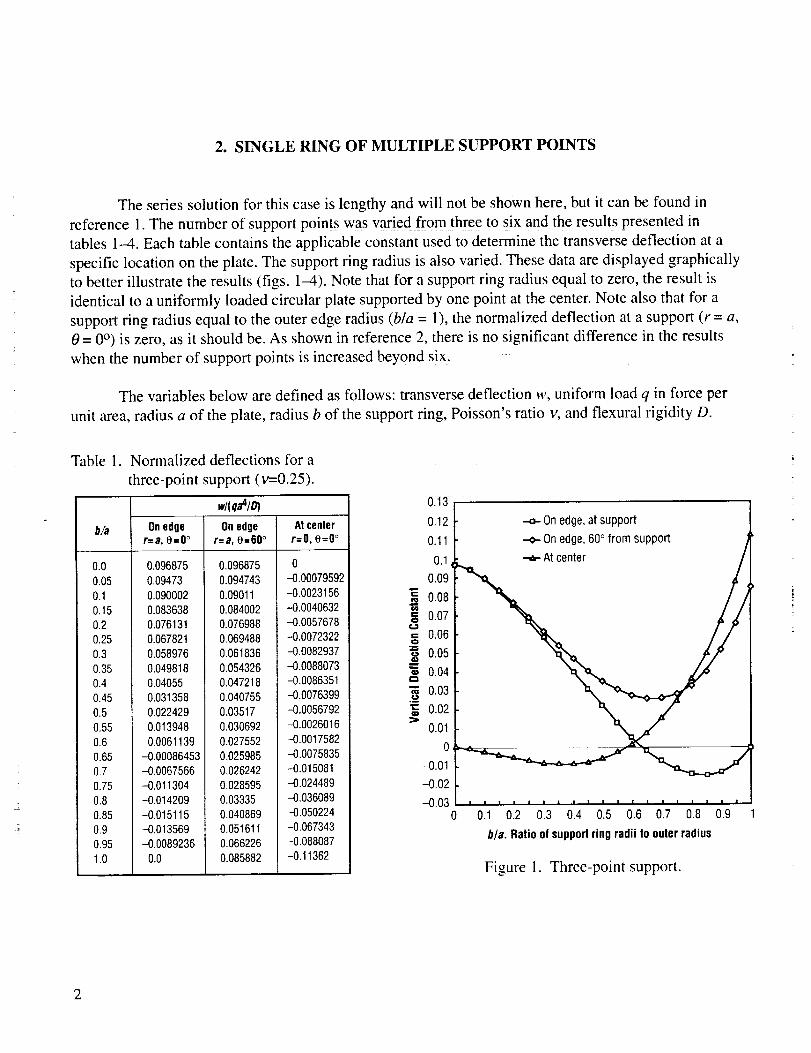
2. SINGLE RING OF MULTIPLE SUPPORT POINTS
The series solution for this case is lengthy and will not be shown here, but it can be found in
reference 1. The number of support points was varied from three to six and the results presented in
tables I-4. Each table contains the applicable constant used to determine the transverse deflection at a
specific location on the plate. The support ring radius is also varied. These data are displayed graphically
to better illustrate the results (figs. 1-4). Note that for a support ring radius equal to zero, the result is
identical to a uniformly loaded circular plate supported by one point at the center. Note also that for a
support ring radius equal to the outer edge radius (b/a = 1), the normalized deflection at a support (r = a,
0 = 0 °) is zero, as it should be. As shown in reference 2, there is no significant difference in the results
when the number of support points is increased beyond six.
The variables below are defined as follows: transverse deflection w, uniform load q in force per
unit area, radius a of the plate, radius b of the support ring, Poisson's ratio v, and flexural rigidity D.
Table 1. Normalized deflections for a
three-point support (v=0.25).
wi(qa41D)
b/a Onedge Onedoe Atcenlerr=a, 0=0 ° r=a, o=60° r=O, 0=0 °
0.0 0.0968750.05 0.094730.1 0.0900020.15 0.0836380.2 0.0761310.25 0.067821O.3 0.0589760.35 0.0498180.4 0.040550.45 0.0313580.5 0.0224290.55 0.0139480.6 0.00611390.65 -0.000864530.7 -0.00675660.75 -0.0113040.8 -0.0142090.85 -0.0151150.9 -0.0135690.95 -0.00892361.0 0.0
0.0968750.094743
0.090110.0840020.0769880.0694880.0618360.054326
0.0472180.0407550.03517
0.0306920.0275520,0259850.0262420.0285950,033350.0408690.0516110.066226
0.085882
0--0.00079592-0.0023156-0.0040632-0.0057678--0.0072322-0.0082937-0.0088073-0.0086351-0.0076399-0.0056792-0.0026016-0.0017582-0.0075835-0.015081-0,024489-0.036089-0.050224-0.067343-0.088087-0.11362
On edge,at support
--e- On edge, 60° from support
•.-a- At center
0.1 0.2 0.3 0.4 0.5 0.6 0.7 0.8
bla. Ratio of supportring radii Io outerradius
Figure 1. Three-point support.
0.9 1

Table 2. Normalized deflections for a
four-point support (v=0.25).
b/a
0.00.050.10.150.20.250.30.350.40.450.50.55
0.60.650.7
0.750.80.850.90.951.0
w/(qa4/_
Onedge Onedge Atcenterr=a, e=O° r=a, e=45° r=O, 0=0 °
0.0968750.0947180.089980.0836420.076226O.068O970.0595360.0507760.042014
O.0334260.0251730.0174110.010290.003966
-0.0013977-0.0056214-0.0085001-0.0097884-0.0091717-0.00619520.0
0.0968750.0947180.0899850.0836660.0763010.0682770.059906O.O514530.043154
0.0352260.0278720.0212880.015670.0112090.00810740.00657520.00684550.00918730.0139370.021570.032954
0-0.0008143-0.0023891-0.004229-0.0060644-0.0077013-0.0089838-0.009778-0.009963-0.0094251
-0.0080536-0.0057361-0.00235530.00221540.00811680.015510.0245850.0355780.04880.0647070.084153
Table 3. Normalized deflections for a
five-point support (v=0.25).
wi(qa41D)
Onedge Onedge Atcenterr=a, e=O° r=a, e=36° r=O, e=O°
b/a
0.00.050.10.150.20.250.30.350.40.450.50.550.60.650.70.750.80.850.90.951.0
0.0968750.0947120.0899580.0835980.0761610.0680210.0594690.0507460.0420580.0335890.02550.0179460.0110680.0050073
-9.4832x10⁻⁵-0.0040905-0.0068171-0.0080849-0.0076547-0.00518280.0
0.0968750.O947120.0899580.0836O.O761690.0680450.0595290.0508740.0423040.0340230.0262220.019080.0127750.00748160.00337560.00063968
-0.000530688.4254×10-50.0027521O.O0784530.016058
0-0.00082045-0.0024137-0.0042844-0.0061629-0.0078555-0.0092066-0.010083-0.010368-0.0099499-0.OO87263-0.0065955-0.00345550.000799240.0062820.0131180.0214540.0314670.0433910.0575730.074692
0.11
0.1
Ew
O
em
0.01
0.11
0.1
0.09
0.08
0.07
0.06
0.05
0.04
0.03
0.02
0.01
0.
-0.01
-0.02
-.o-On edge, atsupport
--o-0n edge, 45°from support
•-,_-At center
0.2 0.3 0.4 0.5 0.6 0.7 0.8 0.9
b/a. Ratio of supportring radii to outer radius
Figure 2. Four-point support.
.-o- On edge, at support
-o-- Onedge, 36° from support
i z ! z z ! ] I I I I I I I I I I ! i
0.1 0.2 0.3 0.4 0.5 0.6 0.7 0.8 0.9
bla. Ratioof support ringradii to outerradius
Figure 3. Five-point support.
3

Table4.
b/a
0.0
0.05
0.1
0.150.2
0.25
0.3
0.35
0.4
0.450.5
0.55
0.6
0.650.7
0.75
0.8
0.85
0.90.95
1.0
Normalized deflections for a six-
point support (v=0.25).
w/(qa4/D)
On edger=a, e=O °
0.096875
0.094709
0.089947
0.083575
0.076122
0.067965
0.059398
0.050666
0.041980.033529
0.025479
0.017987
0.011196
0.0052455
0.00026902
-0.0035977-0.0062118
-0.0074135-0.007007
-0.0047165
0.0
On edger=a, 8=30 °
0.096875
0.094709
0.089947
0.083575
0.076123
0.067968
0.0594090.050693
0.042041
0.033649
0.0257
0.018367
0.011818
0.0062157
0.0017249-0.0014877
-0.0032473
-0.0033622
-0.0016062
0.00232820.0090156
At center
r=O, e=O °
0
-0.0008231
-0.0024243
-0.0043082
-0.0062054
-0.0079218
-0.0093022
-0.010214
-0.010538-0.010168
-0.0089995
-0.0069353
-0.0038785
0.00026869
0.0056073
0.012246
0.020307
0.0299340.041316
0.054729
0.070726
0.11
0.01
-.o- On edge, at support
--o- On edge, 30 ° from support
At center
0.2 0.3 0.4 0.5 0.6 0.7 0.8 0.9
b/a. Ratio of support ring radii 1o outer radius
Figure 4. Six-point support.
=
2
4

3. MULTIPLE RINGS OF EQUALLY SPACED SUPPORT POINTS
The solution to the multiple ring problem is described in a paper by Nelson, Lubliner, and Mast. 2
A solution for a single ring of discreet support points is derived in appendix B of reference 2. The
multiple ring solution 2 is expressed as the summation of single ring solutions with each ring weighted by
its portion of the total load reacted. This summation of weighted single ring solutions is not easily
obtained for the analyst with only a basic understanding of plate theory and the method of superposition.
The solution is complicated and lengthy, but results may be obtained quickly with the aid of a computer.
In 1998, a summer faculty fellow, Dr. Toby Boulet of the University of Tennessee, attempted to
develop a true, closed-form solution. In the process, he developed a Mathcad® (a registered trademark of
MathSoft, Inc.) document using the solution in reference 2. This document can be used to determine
transverse deflections of a uniformly loaded circular plate resting on multiple rings of equally spaced
support points, multiple rings of equally spaced support points with a center support point, or a single
ring of equally spaced support points with or without a center support. The number of rings and support
points must be two or greater to obtain results. Deflections for a single ring of points may be found by
specifying different azimuthal positions of two support rings located at the same radius. To create a
center support point, the radius of one ring must he set equal to zero. Dr. Boulet programmed the
following equations in Mathcad:
v:= 0.25 Poisson's ratio
j] (_,_) := (f12 + _2). ln(fi) +
f2(_,/3) := ([32 + _2). In(_) +
2 i+v
l 22 l+v
[3+v-(1-v)._ 2]
3 + v - (1 - v)./3 2]
J:=20 (number of terms in Fourier expansion)
J:= 1,2 .... J
A(j, fl, N). flN'J [ ( 1 ]_2 )= 37V (l-v). N.j-I N-7.j+
-1
8 . l+v /(N.j) 2 (N.j-1).(1-v) ]

B(j, fl, N) := _flN.j .__1-v .( 13+v N.j N.j+I
C(j,fl, N) :=-1. fiN.j+2
N.j.(N.j+I)
flN.j
D(j,_,N) := l_. j.(N. j-1)
E(j, fl, N) := A(j, fl, N) -_N.j.(N.j-I)
_-(N.j)
F(j,_,N):=B(j, fl, N) W.j.(N.j+l)
rl(j,_,fl, N):= A(j,_,N)._ N'j + B(j,fl, N)._ N'j+2 +C(j, fl, N)._ -(N'j) + D(j, fl, N)._ -(N'j)+2
Z(j,_,/3, N) := E(j, fl, N)'_ N'j + F(j, fl, N)'_ N'j+2
wj(j,_,fl, N) "= if(_ < fl,)t(j,_,fl, N),o(j,_,fl, N))
F(_,fl, U,O):= fu(_,fl)- 2 wj(j,_,fl, N)c°s(N" j'O))j
N R :=? (integer number of rings)
NI
N2
N: = : N i
NNR
is the number of supports in each ring (>1).
6

_NR _
/3i is the ring radius divided by the outer radius of the plate•
41
0 R]_i is the azimuthal (clocking angle) location (radians) of supports in each ring.
Note that the supports within each ring are equally spaced; that is, if NI=3, the support points in ring 1
are 120 ° apart or, if Nj =4, they are 90 ° apart and so on.
s:= 1,2 .... N R k:=l,2 .... N R
bk,s := F( flk ,fls, Ns, (Pk - dPs)
t := 2,3...N R
Ki,k:= 1
Kt,k := bt,k - bl,k
h := XX.XX" in.
p:= YY.YY. lb__f_f,hin. 3
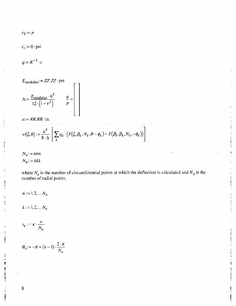
Cl:= P
c t:= 0- psi
q:= K -1 • c
Emodulus:= ZZ.ZZ. psi
A: = Em°dulus " h3 q =
a: = RR.RR. in.
a4 1w(_,0) := __-_-__• qk.(F(_,_k,Nk,O-(_k)-F(fll,flk,Nk,-Ok))
where N n is the number of circumferential points at which the deflection is calculated and N_: is the
number of radial points.
n "= 1,2 .... N.
k'=l,2 .... N_,-
a
• = Ic.--N_-
2.,7'0,,:= -zr + (n - 1).--
N n
rx
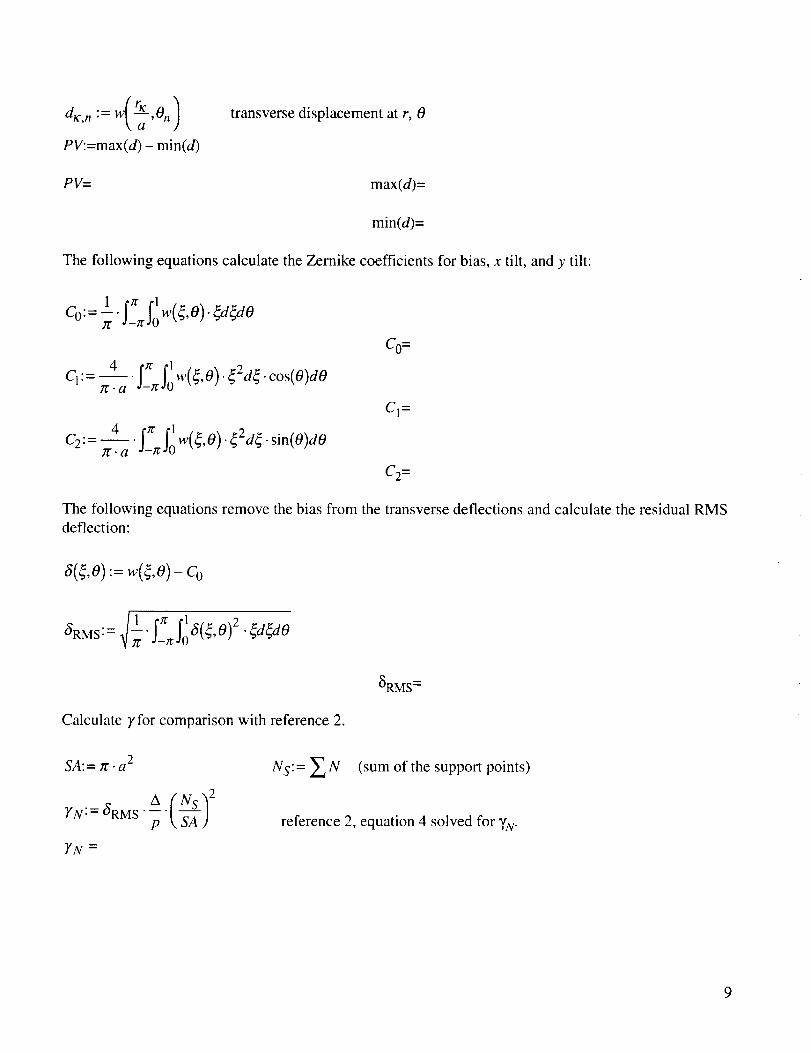
PV:=max(d) - min(d)
transverse displacement at r, 0
PV= max(d)=
min(d)=
The following equations calculate the Zernike coefficients for bias, x tilt, and y tilt:
-. w(¢O).¢d dOIf
C2:: 4 ._.x_lr 1/:a SOw(_'O)'¢2d_'sin(O)dO
CO=
Cl=
C2=
The following equations remove the bias from the transverse deflections and calculate the residual RMSdeflection:
6(¢o):: w(¢O)-Co
_RMS =
Calculate 7for comparison with reference 2.
2SA: = ;,r . a
YN:= 6RMS p 1_SA )
YN =
NS:= _., N (sum of the support points)
reference 2, equation 4 solved for YN-
This concludestheMathcadinput.Thecasesin table 1of reference2 weresolvedwith thisinput andtheresultsconvertedto aform for comparison.Thesamecasesweresolvedvia thefiniteelementmethod(FEM) with NASTRANfor furthervalidation,andtheseresultsarealsoshownintable5. No attemptwasmadeto explainthediscrepanciesbetweentheresultsfrom reference2 andthosefrom NASTRAN ortheequationsabove.TodeterminetheRMS deflection(with biasremoved;thatis, thefirstZernikecoefficient),useequation(4) from reference2 shownbelow.
aRMS = _'N D _, N S ) "
Mathcad or NASTRAN deflections may be illustrated graphically with various software packages.
Once the results are generated, they can be plotted internally or exported to a spreadsheet and plotted
externally. Results for the 4-ring, 12-point support in table 5 are shown in figures 5"9. Note that deflec-
tion downward is positive with the exception of the PATRAN fringe plot of NASTRAN results where
the downward direction is negative.
The Mathcad-generated deadweight deflections shown in figure 5 are for a 0.1-i n. thick, 20-in.
diameter aluminum plate. Note the zero deflection at the inner and intermediate ring support points.
Figures 6-9 illustrate different ways of displaying the deadweight deflections of the aluminum plate.
10
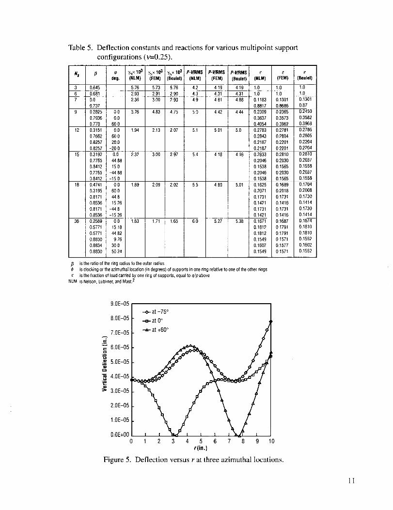
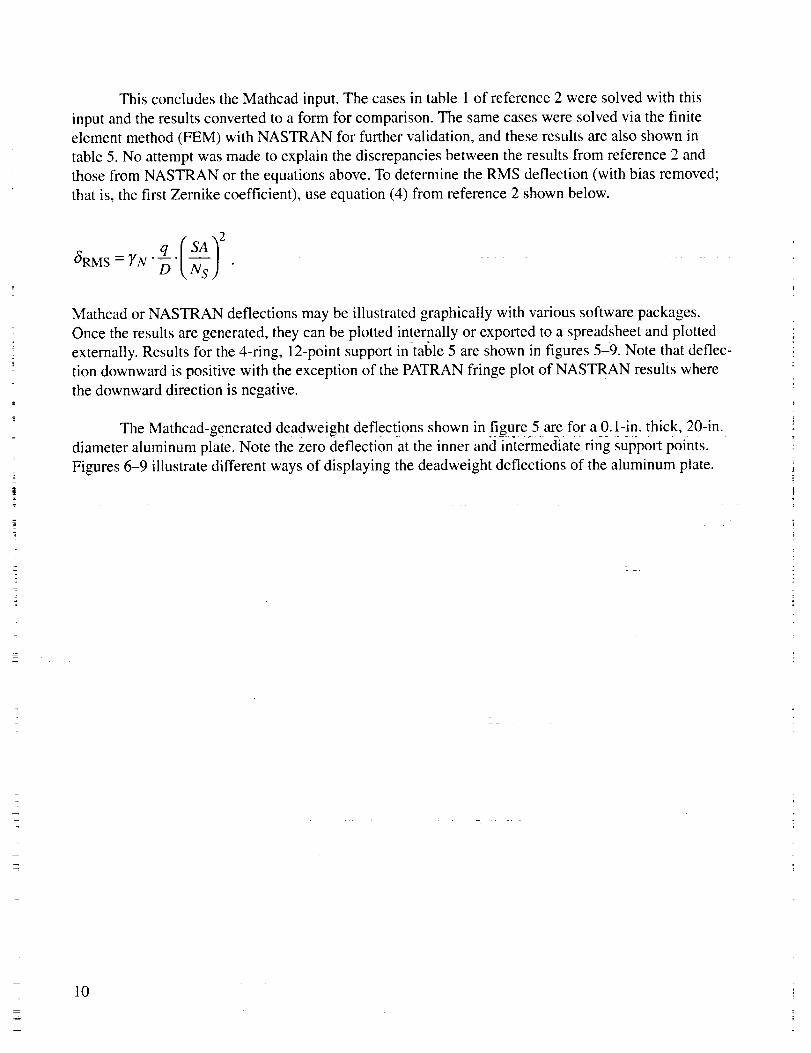
Table 5. Deflection constants and reactions for various multipoint support
configurations (v=-0.25).
Ns
3
6-, 0.6,._ 81
7 0.0
0.737
9 0.2825
0.7936
0.770
12 0.3151
0.7662
0.8257
0.8257
15 0.3192
0.7765
0.8412
0.7765
0.8412
18 0,4741
0.3195
0.8171
0.8536
0.8171
0.8536
36 0.2569
0.5771
0.5771
0.8830
0.8834
0.8830
,6 {o yNxll_ "/Nxl03 YNXl_ P-I/]RMS P-V/RMS P-V/RMS e e e
deg. (NLM) (FEM) (8oulet) (NLM) (FEM) (8oulet) (NLM) (FEM) (Boulet)
0,645 " " 5.76 " 5.73" 5,76 4.2 4,19 4,19 1.0 1.0 1.0
2.93 2.91 2.90 4.3 4.3t 4.31 1.0 1.0 1.0
2.36 3.00 2.93 4.9 4.81 4.88 0.1183 0.1301 0.1301
0.8817 0.8686 0.87
5.0 4,42 4.44 0.2309 0.2365 0.24500.0 3.76 4.83 4.75
0.0
60.0
0.0 1.94 2.13 207
60.0
20.0
-20.0
0.0 2.32 3.00 2.97
44.88
150
-44.88
-15.0
0.0 1,89 2.09 2.02
60.0
44.8
15.26
-44.8
-15.26
0.0 1.63 1.71 1.65
15.18
44.82
9.76
30.0
50.24
5.1 5.01 5,0
5.4 4.18 4,16
5.5 4.89 5.01
6.0 5.27 5.38
0.3637 0,3573 0.3582
0.4054 0.3962 0.39680.2783 0.2781 0.2786
0.2843 0.2804 0,2805
0.2187 0.2201 0.2204
0,2187 0.2201 0.2204
0.2833 0.2810 0.2810
0.2046 0.2030 0.2037
0.1538 0.1565 0.1558
0.2046 0,2030 0.2037
0,1538 0.1565 0.1558
0.1625 0.1689 0.1704
0.2071 0.2018 0.2008
0.1731 0,1731 0,1730
0.1421 0.1416 0.1414
0.1731 0.1731 0.1730
0,1421 0.1416 0.1414
0.1671 0.1687 0.1674
0.1812 0.1791 0.1810
0.1812 0.1791 0.1810
0.1549 0.1571 0.1552
0.1607 0,1577 0.1602
0.1549 0.1571 0.1552
,8 is the ratio of the ring radius to the outer radiusis clocking or the azimuthal location (in degrees) of suppods in one ring relative to one of the other rings
_" is the fraction of load carried by one ring of supports, equal to qlp aboveNLM is Nelson, Lubliner, and Mast.2
9.0E-05
8.0E-05
7.0E-05
.w
= 6.0E-05o
5.0E-05(13
4.0E-05
=_ 3.0E-05
2.0E-05
1.0E-05
O.OE+O0
Figure 5.
--.o- at -75 °
.-o- at 0°
i i _ i i 1 j.. zuq !
1 2 3 4 5 6 7 8 9 10r(in.)
Deflection versus r at three azimuthal locations.
11
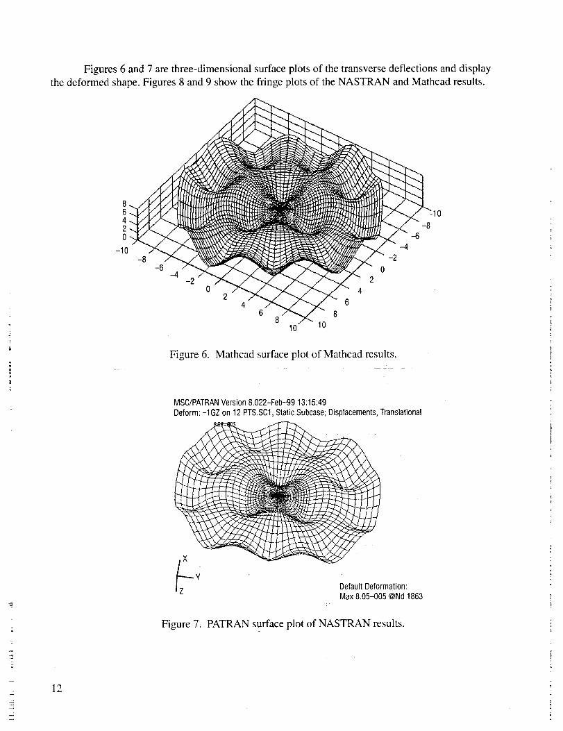
Figures 6 and 7 are three-dimensional surface plots of the transverse deflections and display
the deformed shape. Figures 8 and 9 show the fringe plots of the NASTRAN and Mathcad results.
12
86420
-10
-20
24
6 88
10 10
02
4
6
Figure 6. Mathcad surface plot of Mathcad results.
MSC/PATRANVersion 8.022-Feb-99 13:15:49
Deform:-1GZ on 12 PTS.SC1.Static Subcase; Displacements, Translationalt;
Default Deformation:Max 8.05-005 @Nd 1863
Figure 7. PATRAN surface plot of NASTRAN results.
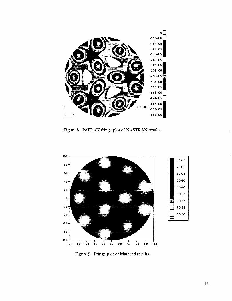
Figure 8. PATRAN fringe plot of NASTRAN results.
10,0
--6.0-
-8.0-
--T [ T--
10.0 -8,0 -6.0 -4,0 -2.0 0.0 2.0 40 6.0 8.0 10.0
Figure 9. Fringe plot of Mathcad results.
8.00E.5
7.00E.5
6.00E-5
5.00E-5
4.00E-5
3.00E-5
200E-5
I,OOE-5
O,OOE-5
13
4. CONCLUSIONS
This TM describes three methods for defining the deflected shape of a uniformly loaded, thin
circular fiat plate supported with multiple discreet points. A comparison of these methods for specific
examples is shown. These methods can provide a preliminary support system design for thin telescope
mirrors. The equations programmed into Mathcad can solve Virtually any system of support points but
are limited to thin, circular fiat plates (although contributio_n !:o thg deflection due to shear could be
added). The finite element method (NASTRAN) can solve any support system and mirror geometry but
requires much more computer time and memory and more of the analyst's time and effort. The tables
and graphs contained in section 2 are sUbsets-of the results of-sec_n 3_and are generated v_ith different
equations. The graphs may be used to determine (he optimum Support ring radius.
. _2 . _
14

REFERENCES
o
°
Pan, H.H.; and Yu, J.C.L.: "Uniformly Loaded Circular Plate Supported at Discrete Points,"
blternational Journal of Mechanical Sciences, pp. 333-340, May 1966.
Nelson, J.E.; Lubliner, J.; and Mast, T.S.: "Telescope Mirror Supports: Plate Deflections on Point
Supports," SPIE, Vol. 332, pp. 212-228, 1982.
15

REPORT DOCUMENTATION PAGE FormApprove_OMB No. 0704-0188
Public reporting burden for this collection of information _s estimated to average 1 hour per response, including the time for reviewing instructions, searching existing data SOurces,
gathering and maintaining the data needed, and completing and reviewing the collection of information. Send comments regarding this burden estimate or any other aspect of this
collection of information, including suggestions for reducing this burden, to Washington Headquarters Services, Directorate for Information Operation and Reports, 1215 Jefferson
Davis Highway, Suite 12C,4+ Arlington, VA 22202-4302, and to the Office of Management and Budget, Paperwork Reduction Project (0704-0188), Washington, DC 20503
1, AGENCY USE ONLY (Leave Blank) 2. REPORT DATE 3. REPORT TYPE AND DATES COVERED
September 1999 Technical Memorandum4. TITLE AND SUBTITLE 5. FUNDING NUMBERS
Deflections of a Uniformly Loaded Circular Plate With Multiple
Support Points
8. AUTHORS
L.D. Craig and J.A.M. Boulet*
7.PERFORMINGORGANIZATIONNAMES(S)ANDADDRESS(ES)
George C. Marshall Space Flight Center
Marshall Space Flight Center, Alabama 35812
9. SPONSORING/MONITORINGAGENCYNAME(S)ANDADDRESS(ES)
National Aeronautics and Space Administration
Washington, DC 20546-0001
8. PERFORMING ORGANIZATION
REPORT NUMBER
M-942
10• SPONSORING/MONITORINGAGENCY REPORT NUMBER
NASA/TM--1999-209631
11. SUPPLEMENTARY NOTES
Structures, Mechanics, and Thermal Department, Engineering Directorate
*University of Tennessee, Knoxville, Tennessee
12a. DISTRIBUTION/AVAILABILITY STATEMENT
Unclassified-Unlimited
Subject Category 39Nonstandard Distribution
12b. DISTRIBUTION CODE
13, ABSTRACT (Maximum 200 words)
This technical memorandum describes a method for determining the transverse deflections of a
uniformly loaded, thin circular plate of constant thickness supported by single or multiple rings
of equally spaced discreet points. The rotations are assumed free at each point. This could have
application in the design of telescope mirror supports that must minimize structural gravitational
deformations. It could also be of general use to the structural analyst.
14. SUBJECT TERMS
circular plates, multipoint support, uniform load, telescope, optics,
mirror supports
15. NUMBER OF PAGES
2O16. PRICE CODE
A0317. SECURITY CLASSIFICATION 18, SECURITY CLASSIFICATION 19. SECURITY CLASSIFICATION 20. LIMITATION OF ABSTRACT
OF REPORT OF THIS PAGE OF ABSTRACT
Unclassified Unclassified Unclassified UnlimitedNSN 7540-01-280-5500 Standard Form 298 (Rev 2-89)
PrEc,cribed by ANSI SId 239-182_-102