deer creek station alternative evaluation analysis and · pdf filedeer creek station...
TRANSCRIPT
Deer Creek Station Alternative Evaluation Analysis and
Site Selection Study
(February 2008, Rev 1)

RUS Environmental Review February 2008
Deer Creek Station
- i -
Table of Contents
1. Introduction ..............................................................................................................1
2. Project Overview .....................................................................................................1
3. Project Need and Justification .................................................................................1
4. Alternative Evaluation Analysis ..............................................................................3
5. Site Selection Study ...............................................................................................10
6. References ..............................................................................................................18

RUS Environmental Review February 2008
Deer Creek Station
- ii -
Index of Figures & Tables
Figure 1. Total System Load and Capability ............................................................... 2
Figure 2. East System Short-Term RFP Proposals...................................................... 7
Figure 3. Renewable Proposals First-Year Bus Bar Costs .......................................... 8
Figure 4. Combined Cycle Unit Process Flow Diagram ............................................. 9
Figure 5. Potential Plant Sites ................................................................................... 11
Table 1. Initial Site Evaluation ................................................................................ 12
Figure 6. Location of White Sites 1 and 2, Brookings County, South Dakota ......... 13
Figure 7. White Site 1 Photo ..................................................................................... 14
Figure 8. White Site 1 Photo ..................................................................................... 15
Figure 9. White Site 1 Photo ..................................................................................... 15
Figure 10. White Site 2 Photo ..................................................................................... 16
Table 2. Incremental Cost Comparison.................................................................... 18

- 1 -
1. Introduction
Basin Electric Power Cooperative (Basin Electric) is a consumer-owned, regional cooperative
headquartered in Bismarck, ND. It generates and transmits electricity to 125 member rural
electric systems in nine states: Colorado, Iowa, Minnesota, Montana, Nebraska, New Mexico,
North Dakota, South Dakota, and Wyoming. These member systems distribute electricity to
about 2.5 million consumers.
Basin Electric has established the need for intermediate generating capacity to service the
increased use of electricity and the resulting load growth including high load factor industrial and
energy-sector (coal, oil, gas, ethanol, and biodiesel) development, and new rural and residential
development. A combined cycle combustion turbine (CCCT) facility was one component of an
optimal resource expansion portfolio determined to be the least-cost portfolio to provide for
future requirements. Basin Electric proposes to construct a new CCCT intermediate resource
located in eastern South Dakota to serve member loads.
The purpose of this report is to describe the proposal, and the technological and siting
alternatives that were evaluated in its development. The report is prepared in accordance with
Rural Utilities Service requirements at 7 CFR 1794.51(c). The material presented here forms in
large part the basis for a more detailed assessment to comply with the National Environmental
Policy Act.
2. Project Overview
The proposed 250 - 300 MW facility would be named Deer Creek Station and would include a
new gas-fired combustion turbine generator set, a heat recovery steam generator (HRSG), and a
steam turbine generator set. The site and facility would be designed to accommodate a possible
future second unit. Firm gas supply and transportation are available and would satisfy Mid-
Continent Area Power Pool (MAPP) accreditation requirements. If a second plant were ever
added to the site, ample gas supply will be available. Power from the facility would be supplied
to Basin Electric’s customers through an interconnection with Western Area Power
Administration’s (Western) transmission system. Western is a federal power marketing agency
with the U.S. Department of Energy (DOE).
3. Project Need and Justification
Existing Resources
Basin Electric’s generating resources include two coal-based power plants in North Dakota – the
Antelope Valley Station, Beulah, and the Leland Olds Station, Stanton; a coal-based power plant
in Wyoming – the Laramie River Station, Wheatland; an oil-based peaking station – the Spirit
Mound Station, Vermillion, S.D.; nine combustion-turbine generators (natural gas) in the
Gillette, Wyo., area; two gas-fired peaking stations – the Groton Generation Station near Groton,
S.D., and the Wisdom Station Unit 2 near Spencer, Iowa; four wind turbines – two near Minot,
N.D., and two near Chamberlain, S.D. Basin Electric purchases the entire output of three wind
farms owned and operated by FPL Energy – one near Edgeley/Kulm and one near Wilton in
North Dakota, and another near Highmore in South Dakota; and two other 750-kilowatt wind

- 2 -
turbines, one located near Pipestone, Minn., and another near Rosebud, S.D. Basin Electric also
purchases the entire production of four recovered energy projects located along the Northern
Border Pipeline. Basin Electric also manages and maintains 2,424 miles of high-voltage
transmission lines; 40 switchyards and substations, and 58 microwave installations used for
communications and system protection.
Projected Energy Requirements
Between 1999 and 2006, Basin Electric system peak demand increased 752 MW from 1,195 to
1,947 MW or approximately 107 MW per year. Basin Electric system energy sales increased 5.3
million MWh (from 6.5 million MWh to 11.8 million MWh) or approximately 760,000 MWh
per year. Basin Electric forecasts peak demand on its system to grow by 1,834 MW from 2006
through 2021 or approximately 122 MW per year. Basin Electric forecasts energy consumption
on its system to grow by approximately 12 million MWh from 2006 through 2021 or
approximately 800,000 MWh per year. The average expected increase in energy sales compared
to the average expected increase in peak demand results in a 75% annual load factor for the
forecasted load growth. Demand is forecasted to double in the next 15 years, with 1,947 MW in
2006 projected to grow 1,834 MW by 2021, and 2006 energy usage at 11.8 million MWh
forecasted to grow 12 million MWh by 2021. The load growth is driven mainly by commercial
sector growth which includes energy related development in the form of coal, oil and gas
development and also increased loads in the residential sector mainly located on the outskirts of
larger cities within the service territory.
The difference in the load forecast plus other obligations (such as sales, losses, and reserves less
Basin’s system-wide load management), and existing and planned generating resources along
with purchases define the load and capability of the Basin Electric system which shows the
amount of surplus capacity on the system. Figure 1 shows Basin Electric’s total system summer
season surplus capacity.
Figure 1. Total System Load and Capability
-1400
-1200
-1000
-800
-600
-400
-200
0
20
08
20
09
20
10
20
11
20
12
20
13
20
14
20
15
20
16
20
17
20
18
20
19
20
20
20
21
Su
rplu
s/D
efic
it (
MW
)
Year

- 3 -
Basin Electric’s total system deficit is 275 MW in 2008 and is forecasted to increase steadily
over time. The two periods that do not produce additional deficits from one year to the next are
when the Dry Fork Station in Wyoming is anticipated to go commercial in 2011 and when a
long-term power supply obligation ends in early 2016. With the addition of the Dry Fork Station
and ending of the long-term power supply obligation, no additional generation is required on
Basin Electric’s Western System and therefore the additional resource required will be on Basin
Electric’s Eastern System.
4. Alternative Evaluation Analysis
Basin Electric’s 2007 Power Supply Analysis (PSA) provides an in depth look at its current
operating system, future load growth and the framework for future expansion, including both
supply-side and demand-side resource expansion. Twelve resource expansion portfolios were
created to meet the forecasted needs of Basin Electric and were evaluated with respect to cost,
performance, and risk. All portfolios included some component of wind energy development.
The twelve portfolios ranged from emphasizing nearly all baseload development to all peaking
development, with various combinations in between.
A number of demand-side and supply-side resource alternatives have been considered as a means
of meeting the forecasted electrical need for Basin Electric. The alternatives evaluated include:
Demand Side Management
Renewable Energy Sources
o Wind
o Solar
o Hydroelectric
o Geothermal
o Biomass Power
o Biogas
o Municipal Solid Waste
Fossil Fuel Generation
o Simple Cycle Combustion Turbines
o Combined Cycle Combustion Turbines
o Microturbines
o Coal Facility
Nuclear Power
Repowering/Uprating of Existing Generating Units
Participation in Another Utility’s Generation Project
Purchased Power / Request for Proposals
New Transmission Capacity
The most economical means of supplying power to a load that varies every hour on an electric
power system is to have three basic types of generating assets available for use. These
generation assets are commonly referred to as baseload, intermediate, and peaking capacity.
- 4 -
Baseload capacity runs at its full capacity continuously throughout the day and night, throughout
the year. The output of baseload-type plants cannot be rapidly decreased or increased to “follow
load.” Baseload units are designed to optimize the balance between high capital/installation cost
and low fuel cost, resulting in the lowest overall production cost under the assumption that the
unit will be heavily loaded for most of its life. Typically, baseload capacity units are operated
around 80 percent capacity factor or more. Coal-fired power plants, nuclear plants, and
hydroelectric plants are examples of baseload generation capacity; however, hydro plants that
follow load are not considered baseload units.
Intermediate capacity units are designed to be “cycled” at low load periods, such as evening and
weekends. The units are loaded up and down rapidly to handle the load swings of the system
while the unit is online. Typically, intermediate capacity units are operated between a 20 and 80
percent capacity factor, or between baseload and peaking.
Peaking capacity is only operated during peak load periods and during emergencies. Very low
capital/installation costs are important due to the fact these units are typically not operated very
much. The production costs are relatively high due to the high cost and volatility in the price of
fuel. Types of peaking capacity power plants include combustion turbines, internal combustion
engine plants, and pumped-storage hydroelectric facilities. Typically, peaking resources are
operated under a 20 percent capacity factor.
The generation types capable of meeting an intermediate need of Basin Electric’s would be the
alternatives that have a capacity factor between 20 percent and 80 percent, which include wind,
solar, hydroelectric and combined cycle combustion turbines. Wind is an intermittent resource
that cannot be scheduled when to operate but does not cost a whole lot due to the fact it is a fuel
displacer. Wind would integrate very well with gas fired generation to produce a more useable
product. Solar is also an intermittent resource that cannot be scheduled when to operate however
it is very costly. Hydroelectric power generally operates between 40 and 50 percent capacity
factor, however it is very dependent on annual rainfall and therefore can go through some long
periods of low generation, and the upper Midwest has seen several years of drought so water is
currently limited. Combined cycle combustions turbines are an excellent source to meet Basin
Electric’s intermediate generating resource need; combined cycles do not tend to have a stable
fuel cost however the fuel is generally there when needed. For these reasons a CCCT facility
was determined to be the most cost effective option to meet Basin Electric’s intermediate
generating resource needs.
Of the twelve resource expansion portfolios analyzed in the PSA, the preferred portfolio included
300 MW of wind, 200 MW of peaking generation, 250 MW of intermediate generation and 600
MW of baseload coal generation. The Deer Creek Station is proposed to meet Basin Electric’s
projected intermediate generation requirement. While baseload and peaking capacity units are
being contemplated for inclusion in Basin Electric’s resource expansion plan, they are not
addressed in this alternative evaluation analysis.
Demand Side Management
Demand Side Management (DSM) is the process of managing the consumption of energy,
generally to optimize available and planned generation resources. According to the Department

- 5 -
of Energy, DSM refers to “actions taken on the customer’s side of the meter to change the
amount or timing of energy consumption. Utility DSM programs offer a variety of measures that
can reduce energy consumption and consumer energy expenses. Electricity DSM strategies have
the goal of maximizing end-use efficiency to avoid or postpone the construction of new
generating plants.”
DSM programs aim to achieve three broad objectives: energy conservation, energy efficiency
and load management. Energy conservation can reduce the overall consumption of electricity by
reducing the need for heating, lighting, cooling, cooking energy and other uses. Energy
efficiency can encourage consumers to use energy more efficiently, and thus get more out of
each unit of electricity produced. Load management allows generation companies to better
manage the timing of their consumers’ energy use, and thus help reduce the large discrepancy
between on-peak and off-peak demand.
Approximately half of the Basin Electric members are utilizing load management to manage
their power purchases from Basin Electric. Basin Electric has implemented a system-wide load
management program on its eastern system which enables Basin Electric to target large loads
and/or generation that are not included in the members’ load management programs to be used
during Basin Electric’s seasonal peak periods. Basin Electric has approximately 6-10 MW of
load management available at this time.
DSM programs are capable of reducing the energy demand and reducing the required capacity of
future additional generation facilities. It is apparent, however, that energy savings through DSM
are not enough to alleviate the need for the intermediate resource fulfilled by the current
proposal.
Repowering/Uprating of Existing Generating Units
Basin Electric has committed to upgrading the high pressure and intermediate pressure (HP/IP)
turbine section of the main turbine at all three units of the Laramie River Station. The Unit 2
upgrade occurred in the spring 2007 maintenance outage, unit 3 is scheduled to occur in the
spring 2008 maintenance outage and unit 1 in the spring 2009 maintenance outage. The upgrade
to the HP/IP turbine is anticipated to increase the net output of each unit by 8-12 MW for a total
of 24-36 MW. Basin Electric could see an additional 10-15 MW from the upgrades of these
turbines, due to its 42.27% ownership share of the Missouri Basin Power Project (MBPP). These
increases in net output are due to efficiency increases, without increasing the fuel input to the
units.
Basin Electric has also committed to retrofitting the low pressure (LP) turbine sections of Unit 2
in the Leland Olds Station. This upgrade when completed in 2009, should increase the net
output by 5.5 MW. This increase in net output is due to efficiency increases, without increasing
the fuel input to the unit.
Basin Electric has also evaluated the option of upgrading the HP/IP turbines at the Antelope
Valley Station; however work within the boiler would need to be done to make this a viable
project. This work would require full “New Source Review” (NSR) for modification of the

- 6 -
boiler. Basin Electric has decided not to move forward with the upgraded turbines at the
Antelope Valley Station.
While Basin Electric has made progress in upgrading existing facilities, it is apparent that the
scale of the improvements does not alleviate the need for the intermediate resource fulfilled by
the current proposal.
Participation in Another Utility’s Generation Project
Basin Electric has been having discussions with some neighboring utilities about participating in
a third unit at the Milton R. Young Station near Center, North Dakota. Basin Electric is looking
at a 100 MW share of a 500 MW unit to be operational in the 2016-2020 time period.
This participation could help meet a portion of Basin Electric’s long-term need for increased
generating capacity in the region, but would not meet the need for its short-term intermediate
resource requirements.
Purchased Power / Request for Proposals
Basin Electric has signed a 25-year contract with the developer of four current Recovered Energy
Generation (REG) power plants, which are fueled by hot exhaust heat off the Northern Border
Pipeline, to purchase the output from four additional REG power plants. There will be one site
each in Montana and Minnesota, and two sites in North Dakota. These additional four sites
should have a total combined output of 22 MW and are anticipated to be operational in 2009.
The generation is environmentally benign, using virtually no additional fuel and producing
virtually zero emissions.
Basin Electric hired Power Systems Engineering (PSE) to develop and issue a Request for
Proposals (RFP) in early 2007 for short- and long-term power supply on both its eastern and
western system. The long-term proposals were used to evaluate against Basin Electric’s self-
build options. The short-term proposals could be utilized to meet some of Basin Electric’s need
in the next couple of years. Renewable proposals were also sought.
Short-term Proposals
Basin Electric received short-term proposals from nine different entities for power products
located in both of Basin Electric’s eastern and western systems. The short-term proposals were
evaluated by PSE.
Figure 2 compares Basin Electric’s eastern system needed generation capacity to the magnitude
of proposals received. From this information it was determined that Basin Electric could
purchase the needed power from the market through 2009 but would need to develop additional
resources to meet the needed obligations beyond 2009. Basin Electric did elect to short-list one
proposal from the proposals received for delivery into Basin Electric’s eastern system. It was
believed that the short-term proposals were more costly than Basin Electric’s self build options.

- 7 -
Figure 2. East System Short-Term RFP Proposals
Long-term Proposals
Basin Electric received four conventional long-term power purchase proposals from two
different entities for either coal generation or a combination combined cycle and simple cycle
generation. It was believed that the four long-term proposals were more costly than Basin
Electric’s self build options. These conventional long-term proposals were evaluated by PSE.
Renewable Proposals
Basin Electric received 12 proposals from nine different entities for wind generation. These 12
wind proposals were located in North Dakota, South Dakota, Montana and Wyoming. Figure 3
shows the anticipated first-year bus bar of each proposal. The renewable proposals were
evaluated by Basin Electric staff.
0
100
200
300
400
500
600
700
800
2008 2009 2010 2011 2012 2013
MW
Year
Intermediate
Baseload
Needed

- 8 -
Figure 3. Renewable Proposals First-Year Bus Bar Costs
Based on the anticipated capacity factor, location and bus bar cost, proposal 3 was short-listed to
be compared to Basin Electric’s own self-build option for wind generation. Proposal 3 is still
being evaluated. Wind generation, however, is not an “on call” resource and therefore is not
capable of fulfilling the purpose and need for an intermediate resource on its own.
New Transmission Capacity
Today there is limited available transmission capacity (ATC) on the transmission system to
move power into the Integrated System (IS) from Nebraska Public Power District (NPPD), Mid-
American Energy Company (MEC), Midwest Independent Transmission System Operator
(MISO) or Saskatchewan. In order to bring in enough power to cover Basin Electric’s total need,
additional transmission would need to be built and there would probably be upgrades needed to
third-party transmission in order to move the power into the region.
The other question becomes is there existing generation outside the region to meet Basin
Electric’s need. The Request for Proposals provided few responses for power outside the IS area
during the short term; one proposal within MISO, one proposal within MEC and one proposal
from within NPPD. One proposal for a long-term output of a new coal plant was received that
would result in either additional transmission to be built or additional wheeling expense to move
the power into the IS or both. Because of these anticipated higher costs, Basin Electric feels it
would be a better economic decision to build the new generation within the IS and therefore
avoid some unnecessary transmission costs to provide power to the membership at the lowest
reasonable cost.
Combined Cycle Combustion Turbine (CCCT)
Combined cycle is a term used when a power producing engine or plant employs more than one
thermodynamic cycle. In a combined cycle power plant (CCPP) or combined cycle combustion
turbine (CCCT) plant, a gas turbine generator generates electricity and the waste heat from the
gas turbine is used to make steam to generate additional electricity via a steam turbine; this last
step enhances the efficiency of electricity generation. In a thermal power plant, high-
$0.00
$10.00
$20.00
$30.00
$40.00
$50.00
$60.00
$70.00
$80.00
1 2 3 4 5 6 7 8 9 10 11 12
$/M
Wh
Site Proposal #
- 9 -
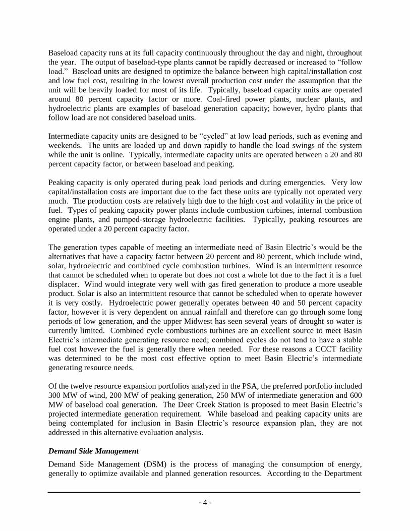
temperature heat as input to the power plant, usually from burning of fuel, is converted to
electricity as one of the outputs and low-temperature heat as another output. As a rule, in order
to achieve high efficiency, the temperature of the input heat should be as high as possible and the
temperature of the output heat as low as possible. This is achieved by combining the Rankine
(steam power system) and the Brayton (gas turbine) thermodynamic cycles. Figure 4 shows a
typical combined cycle unit process flow diagram.
Figure 4. Combined Cycle Unit Process Flow Diagram
The thermal efficiency of a combined cycle power plant is normally in terms of the net power
output of the plant as a percentage of the lower heating value of the fuel. Typical combined
cycle plants are powered by natural gas, although other sources of fuel can be used such as fuel
oil or synthetic gas.
Combined cycle equipment is pre-engineered and factory packaged to minimize installation time
and cost. All major equipment (gas turbine generator, heat recovery steam generator, and steam
turbine generator) is shipped to the field as assembled and tested components. CCCT plants have
demonstrated high reliability and low operations and maintenance costs.
The capital cost component of the levelized cost of CCCT power is approximately $18/MWh for
a plant that runs at about 60 percent annual capacity factor. The total levelized cost of CCCT
power is projected to be approximately $92/MWh for about 5,250 hours of operation in a year or
about 60 percent annual capacity factor. If a CCCT plant were operated at 80 percent annual
capacity factor, the levelized cost of power would be about $86/MWh. Most of the power-
generation cost for a CCCT plant is from the variable/fuel cost at approximately $69/MWh,
assuming the cost of fuel is about $6.50/MMBtu. Natural gas cost is highly variable and strongly
affected by the economy, production and supply, demand, weather, and storage levels.
Traditionally, demand for natural gas peaks in the coldest months, but with the nation’s power
increasingly being generated by natural gas, demand also spikes in summer, when companies
fire-up peaking plants to provide more power for cooling needs.

- 10 -
Summary of Alternatives
For the reasons described above, neither demand side management, repowering, project
partnerships, purchased power, nor new transmission capacity meet the need for the intermediate
resource fulfilled by the current proposal. CCCT facilities have been a proven solution for
meeting intermediate resource requirements industry wide and this type of facility logically
meets Basin Electric’s intermediate generating resource need.
5. Site Selection Study Basin Electric has established the need for additional intermediate capacity to serve forecasted
member load growth. Basin Electric has concluded that an intermediate resource located in
eastern South Dakota is necessary to fulfill its member obligations. Eastern South Dakota was
selected because it is outside the existing North Dakota export transmission constraint but within the
Integrated Transmission System (IS) and proximity to an adequate fuel supply. The IS is owned by
Western Area Power Administration, Basin Electric Power Cooperative and Heartland Consumers
Power District. As discussed in the Alternative Evaluation Analysis, a CCCT facility appears to
be the best alternative for Basin Electric’s use as an intermediate resource. There were several
factors considered in evaluating potential plant sites: access to a high voltage transmission
system with available capacity, fuel supply, water supply, existing land use and terrain, and
proximity to residences.
Initially, five potential plant sites were identified in eastern South Dakota. Following a
preliminary review of environmental constraints including obvious exclusion or avoidance areas
and existence of required factors such as fuel supply and transmission lines, the number of
proposed locations was reduced to two candidate sites.
The five potential plant sites initially chosen are shown on Figure 5. The potential sites are
located within Basin Electric membership areas in eastern South Dakota. The Groton Site is
located near Aberdeen, SD, the Watertown Site is about halfway between Watertown and
Brookings, SD, and the White Sites 1, 2, and 3 are located near Brookings, SD.

- 11 -
Figure 5. Potential Plant Sites
BEPC staff completed an initial field review of these five sites in August and September, 2007.
The purpose of this site screening field review was to verify the accuracy of databases used to
locate existing natural gas pipelines, transmission lines and substations, and the spatial
relationship of these resources to each other in the area surrounding the potential sites. Existing
water supplies and transportation access were also documented. Potential environmental and
human constraints in the area surrounding the potential sites were also noted. Regional air
quality constraints, land use compatibility, geologic hazards, potential biological or cultural
resource constraints, wetlands, and any potential for hazardous waste or spill sites in the general
area were considered. Based on this initial field review, three of the five potential sites were
rejected from future consideration. This evaluation is depicted in Table 1. The three sites that

- 12 -
were evaluated as the lowest rankings and therefore rejected from further study were the Groton
Site, the Watertown Site, and White Site 3.
Table 1. Initial Site Evaluation
Site Groton WaterTown White
Site 1
White
Site 2
White
Site 3
Site
Conditions
Congested Greenfield Greenfield Greenfield Greenfield
Transmission
Access
2 3 1 2 2
Transmission
Capacity
2 1 1 1 1
Substation
Required?
1 3 1 3 1
Fuel
Supply/Length
3 1 3 2 3
Water Supply 3 3 2 2 2
Land Use 1 3 1 1 1
Terrain 2 2 1 1 3
Proximity to
Residences
3 3 1 2 3
Ranking 17 19 11 14 16
Ranking: 1 – Most Favorable, 2- Moderate and 3- Least Favorable
The Groton Site was rejected due to property and transmission constraints due to the previous
installation of two simple cycle peaking facilities and also the limitation of the water and fuel
supply. The Watertown Site was rejected due to the long distances to the nearest substation and
water supply, the increase costs associated with the need for an additional substation and
congested land use issues. White Site 3 was rejected because it is not large enough for a CCCT
facility and terrain suitability.
The two sites that were suitable for further study following the initial screening were White
Sites 1 and 2 (see Figure 6). These two sites were evaluated in more detail according to the
screening criteria listed in Table 1 and an incremental cost comparison has been prepared to
further evaluate the two sites.

- 13 -
Figure 6. Location of White Sites 1 and 2, Brookings County, South Dakota.
Fuel Supply
The two sites under consideration (see Figures 7 thru 10) are located near the Northern Border
Pipeline (NBPL), thus ensuring a reliable fuel source is available. White Site 1 is located
approximately 6 miles southeast of White, South Dakota in the northeast quarter of Section 25,
Township 111 North, Range 48 West, of the Fifth Principal Meridian, Brookings County. White
Site 2 is located approximately 4 miles east-northeast of White, South Dakota in the northwest
quarter of Section 2, Township 111 North, Range 48 West, of the Fifth Principal Meridian,
Brookings County. Firm gas supply and transportation agreements are available with Northern
Border Pipeline that meet Mid-Continent Area Power Pool (MAPP) accreditation requirements.
The compressor station locations are also favorable because of existing above-ground pipeline
taps. White Site 1 is located further from the NBPL than White Site 2; however the rugged
topography of the area near White Site 2 dictates that the pipeline to either site would be nearly
the same length. As a result, neither site has an advantage over the other with respect to fuel
supply.

- 14 -
Figure 7. View looking south from the north boundary of White Site 1.
Western and Xcel substations are in the background.

- 15 -
Figure 8. View looking north from the south boundary of White Site 1.
Figure 9. View looking northeast from the south boundary of White Site 1.

- 16 -
Land Use/Terrain
The terrain in the White Site 1 study area is relatively flat and slopes from the northwest to the
southeast; the area surrounding the site is well-drained. The area under consideration for White
Site 1 is agricultural, consisting primarily of farmland. The elevation of White Site 1 is
approximately 1850 feet above mean sea level (msl). The terrain around the White Site 2 study
area is very flat consisting primarily of farmland. The elevation of White Site 2 is approximately
1935 feet above mean sea level (msl). Since both sites are relatively flat, neither site has an
advantage over the other with respect to constructability. However, White Site 1 is preferred
with respect to terrain because the slope of White Site 1 would allow better drainage than White
Site 2. Also, the lower elevation of White Site 1, as compared to White Site 2, would yield
slightly better gas turbine performance. This is because gas turbine performance decreases as
elevation increases due to a decrease in air density.
Water Supply Water usage for the proposed CCCT facility would be minimal because an air cooled condenser
would be used to condense the steam that exits the steam turbine, rather than a water cooled
condenser and cooling tower combination for this purpose. The facility would use water for
control of nitrogen oxide (NOx) emissions, evaporative cooling, and for make-up water needs. A
single unit facility would normally consume 25 gallons of treated water per minute with a
maximum of 60 gallons of treated water per minute. The facility would use a groundwater
Figure 10. View looking southeast from the northwest corner of White Site 2.
- 17 -
source as no rural water distribution system currently exists at either site and because systems
nearby are approaching full capacity. Currently, the exact location of a sufficient groundwater
source for the sites remains undetermined; several test wells would be required to locate a source
capable of delivering both sufficient water supply and properties to satisfy various station service
water requirements. Since both sites would use a groundwater source, neither site has an
advantage over the other with respect to water supply.
Transmission Access
Existing transmission in the vicinity of White Site 1 includes a Western 345 kV line just west of
the site. An existing 345/115 kV substation owned by Western is located about 1/2 mile
southwest of the potential site. There are presently two 115 kV transmission lines (one owned
by Western and one owned by East River Electric Power Cooperative) tied into this substation.
A 345/115 kV substation owned by Xcel is located about 1/3 mile south of White Site 1. White
Site 2 is located approximately 1/3 mile west of the same Western 345 kV line, and 4 3/4 miles
north of the same 345/115kV substation owned by Western and the 345/115 kV substation
owned by Xcel. Power from a CCCT facility located at White Site 1 would be interconnected
into the existing 345 kV bus in Western’s White Substation via a new ½ mile 345 kV
transmission line. At White Site 2 a new substation would be required to be constructed and
would interconnect to Western’s 345 kV transmission line thru two 3/4 mile 345 kV lines. The
shorter transmission line associated with White Site 1 and no requirement to construct a
substation would cause less land to be disturbed by construction activities and would also be less
costly due to fewer materials and less labor being required. As such, White Site 1 has a
significant advantage over White Site 2 since it is much closer to the high voltage transmission
system and existing substation.
Proximity to Residences
A facility on White Site 1 would be located approximately 1 mile away from the nearest
occupied residence while on White Site 2 it would be located approximately 1/2 mile away from
the nearest occupied residence. Therefore, White Site 1 has an advantage over White Site 2
because it is located farther away from the nearest occupied residence.
Site Selection Summary
Based on the evaluation criteria applied in the site selection process (access to a high voltage
transmission system with available capacity, fuel supply, water supply, existing land use and
terrain, and proximity to nearest occupied residence), White Site 1 appears to offer considerable
advantages versus White Site 2. The terrain of White Site 1 allows for better drainage than
White Site 2. The lower elevation of White Site 1 means that a gas turbine would perform better
at White Site 1 than at White Site 2. The relatively short distances to high voltage transmission
facilities at White Site 1 would cause fewer disturbances of natural resources and be less costly
because fewer materials and less labor would be required. White Site 1 is also further away from
the nearest occupied residence than White Site 2. Table 2 depicts the incremental costs
associated with White Site I and White Site 2. For the reasons listed above and the increased
costs associated with White Site 2, White Site 1 is considered the Preferred Site.

- 18 -
Table 2. Incremental Cost Comparison
White Site 1 White Site 2
Site Conditions Base Same
Transmission Access Base $750,000
Transmission Capacity Base Same
Substation Base $10,000,000
Fuel Supply/Length Base ($1,000,000)
Water Supply Base Same
Land Use Base Same
Terrain Base ($500,000)
Proximity to Residences Base Same
Cost Base $10,250,000
6. References 1.) Technology Characterization: Microturbines, Prepared by Energy Nexus Group for
Environmental Protection Agency – Climate Protection Partnership Division, March
2002, <http://www.epa.gov/chp/chp_support_tools.htm#catalogue>.
2.) U.S. Department of Energy – Energy Information Administration, Annual Energy
Outlook 2006, (Washington, D.C.: February 2006) DOE/EIA-0383(2006),
<http://www.eia.doe.gov/oiaf/aeo/>.
3.) U.S. Department of Energy Hydropower Program – Idaho National Laboratory, Idaho
National Laboratory, January 2007, <http://hydro2.inel.gov>.
4.) U.S. Department of Energy – National Renewable Energy Laboratory, Power
Technologies Energy Data Book, Fourth Edition, August 2006, NREL/TP-620-39728,
<http://www.nrel.gov/analysis/power_databook/>.