deepgomimo: deep learning-aided generalized optical mimo
TRANSCRIPT

1
DeepGOMIMO: Deep Learning-Aided GeneralizedOptical MIMO with CSI-Free Blind Detection
Xin Zhong, Chen Chen, Member, IEEE, Shu Fu, Zhihong Zeng, and Min Liu
Abstract—Generalized optical multiple-input multiple-output(GOMIMO) techniques have been recently shown to be promisingfor high-speed optical wireless communication (OWC) systems.In this paper, we propose a novel deep learning-aided GOMIMO(DeepGOMIMO) framework for GOMIMO systems, where chan-nel state information (CSI)-free blind detection can be enabledby employing a specially designed deep neural network (DNN)-based MIMO detector. The CSI-free blind DNN detector mainlyconsists of two modules: one is the pre-processing module whichis designed to address both the path loss and channel crosstalkissues caused by MIMO transmission, and the other is the feed-forward DNN module which is used for joint detection of spatialand constellation information by learning the statistics of boththe input signal and the additive noise. Our simulation resultsclearly verify that, in a typical indoor 4 × 4 MIMO-OWC systemusing both generalized optical spatial modulation (GOSM) andgeneralized optical spatial multiplexing (GOSMP) with unipolarnon-zero 4-ary pulse amplitude modulation (4-PAM) modulation,the proposed CSI-free blind DNN detector achieves near the samebit error rate (BER) performance as the optimal joint maximum-likelihood (ML) detector, but with much reduced computationalcomplexity. Moreover, since the CSI-free blind DNN detector doesnot require instantaneous channel estimation to obtain accurateCSI, it enjoys the unique advantages of improved achievable datarate and reduced communication time delay in comparison to theCSI-based zero-forcing DNN (ZF-DNN) detector.
Index Terms—Optical wireless communication, multiple-inputmultiple-output, deep learning, blind detection.
I. INTRODUCTION
DUE to the exhaustion of radio frequency (RF) spectrumresources, optical wireless communication (OWC) which
explores the infrared, visible light or ultra-violet spectrum hasbeen envisioned as a promising candidate to satisfy the ever-increasing data demand in future indoor environments [1]. Inrecent years, bidirectional OWC, which is also named lightfidelity (LiFi), has been widely considered as one of the keyenabling technologies for 5G/6G and Internet of Things (IoT)communications [2]–[5]. Although OWC systems have manyinherent advantages such as abundant license-free spectrum re-sources, no electromagnetic interference (EMI) and enhancedphysical-layer security, the practically achievable capacity of
This work was supported in part by the National Natural Science Foundationof China under Grant 61901065, in part by the Fundamental ResearchFunds for the Central Universities under Grant 2021CDJQY-013 and Grant2020CDJQY-A001, and in part by the China Postdoctoral Science Foundationunder Grant 2021M693744.
X. Zhong, C. Chen, S. Fu, and M. Liu are with the School of Microelec-tronics and Communication Engineering, Chongqing University, Chongqing400044, China (e-mail: {c.chen, 201912131098, shufu, liumin}@cqu.edu.cn).
Z. Zeng is with the LiFi Research and Development Centre, Institute forDigital Communications, The University of Edinburgh, EH9 3JL, UK (e-mail:[email protected]).
OWC systems is largely limited by the small modulation band-width of commercial off-the-shelf (COTS) optical elements,especially for illumination light-emitting diodes (LEDs) [6].
As a very natural way to efficiently improve the achievablecapacity of indoor OWC systems using LEDs, multiple-inputmultiple-output (MIMO) transmission has attracted great at-tention recently, which fully exploits the existing LED fixturesin the ceiling of a typical room to harvest substantial diversityor multiplexing gain [7]–[9]. So far, various optical MIMOtechniques have been introduced for OWC systems, amongwhich optical spatial multiplexing (OSMP) and optical spatialmodulation (OSM) are two most popular ones. Specifically,OSMP can achieve full multiplexing gain and hence a relativehigh spectral efficiency, but suffers from severe inter-channelinterference (ICI) [10]. In contrast, OSM can remove ICI byactivating a single LED to transmit signal at each time slot.Although OSM can transmit additional index bits, only oneconstellation symbol can be transmitted at each time slot,and hence it is challenging for OSM systems to achieve highspectral efficiency [11]. Lately, generalized optical MIMO(GOMIMO) techniques, including generalized OSM (GOSM)and generalized OSMP (GOSMP), have been further proposedto boost the capacity of MIMO-OWC systems [12]–[15]. InGOSM systems, multiple LEDs are activated to transmit thesame signal, and therefore more index bits can be transmittedand the diversity gain can also be increased. In GOSMPsystems, only a subset of LEDs are activated to transmit differ-ent signals, resulting in reduced multiplexing gain. However,additional index bits can be transmitted and the ICI can alsobeen reduced in GOSMP systems. Our previous work [15]has already clearly demonstrated the superiority of GOMIMOtechniques in comparison to conventional OSM and OSMP.
In order to successfully implement GOMIMO systems, anefficient MIMO detection scheme should be adopted. Gen-erally, the joint maximum-likelihood (ML) detector serves asthe optimal detector for GOMIMO systems [16]. Nevertheless,the ML detector usually has high computational complexity,making it infeasible in practical applications. Instead, thecombination of zero-forcing (ZF) equalization and ML detec-tion can be a practical low-complexity detection scheme forGOMIMO systems [16]. However, ZF equalization inevitablyleads to noise amplification due to high channel correlationin typical indoor MIMO-OWC systems. Moreover, the ZF-ML detector also suffers from the adverse effect of errorpropagation, since the detection error of spatial symbols mightpropagate to the estimation of constellation symbols.
With the rapid development of machine learning technology,deep learning has revealed its great potential in wireless com-
arX
iv:2
110.
0408
4v1
[ee
ss.S
P] 8
Oct
202
1

2
munication systems [17], [18]. Most recently, deep learningtechniques have also been applied in OWC systems for binarysignaling design [19], mitigation of both linear and nonlinearimpairments [20], energy-efficient resource management [21],and so on. More specifically, a ZF-based deep neural network(DNN) detection scheme has been proposed for MIMO detec-tion in GOMIMO systems [22]. The obtained results in [22]show that the ZF-DNN detector can achieve comparable biterror rate (BER) performance as the optimal joint ML detectorwith greatly reduced computational complexity. Nevertheless,the ZF-DNN detector takes the ZF equalized signal as itsinput, which requires accurate channel state information (CSI),i.e., the MIMO channel matrix, to successfully perform ZFequalization. Although CSI can be estimated by using trainingsymbols [23], training-based instantaneous channel estimationinevitably causes both the loss of achievable data rate and theincrease of communication time delay.
In this paper, to address the disadvantages of CSI-basedZF-DNN detection due to the requirement of instantaneousCSI for ZF equalization, we for the first time propose aDeepGOMIMO framework for GOMIMO systems where CSI-free MIMO detection is achieved by a novel blind DNN de-tection scheme. By adding a specially designed pre-processingmodule before the feed-forward DNN module, CSI-free blinddetection can be successfully enabled for GOMIMO systems.Numerical simulations are extensively conducted to evaluatethe performance of the proposed CSI-free blind DNN detector,which is also compared with other three benchmark schemesincluding the joint ML detector, the ZF-ML detector and theZF-DNN detector. Our simulation results verify the advantagesof the proposed CSI-free blind DNN detector in comparisonto other benchmark schemes in GOMIMO systems.
The rest of this paper is organized as follows. In Section II,we describe the mathematical model of a general GOMIMOsystem. In Section III, we introduce four detection schemesfor GOMIMO systems. Detailed simulation setup and resultsare presented in Section IV. Finally, Section V concludes thepaper.
II. SYSTEM MODEL
In this section, we introduce the mathematical model of ageneral GOMIMO system equipped with Nt LEDs and Nrphoto-detectors (PDs). The channel model is first describedand then the basic principle of GOMIMO is further reviewed.
A. Channel ModelLetting x = [x1, x2, · · · , xNt ]
T be the transmitted signalvector, H represent the Nr × Nt MIMO channel matrix andn = [n1, n2, · · · , nNr
]T denote the additive noise vector, thereceived signal vector y = [y1, y2, · · · , yNr
]T is obtained by
y = Hx + n, (1)
and the corresponding channel matrix H can be expressed by
H =
h11 · · · h1Nt
.... . .
...hNr1 · · · hNrNt
, (2)
where hrt (r = 1, 2, · · · , Nr; t = 1, 2, · · · , Nt) denotes thedirect current (DC) channel gain between the r-th PD andthe t-th LED. Assuming that each LED follows the generalLambertian radiation pattern and only the line-of-sight (LOS)transmission is considered, hrt is calculated by [24]
hrt =(l + 1)ρA
2πd2rt
cosm(ϕrt)Ts(θrt)g(θrt)cos(θrt). (3)
In (3), l = −ln2/ln(cos(Ψ)) denotes the Lambertian emissionorder, with Ψ being the semi-angle at half power of the LED;ρ and A represent the responsivity and the physical area ofthe PD, respectively; drt is the distance between the r-th PDand the t-th LED; ϕrt and θrt are the emission angle and theincident angle, respectively; Ts(θrt) is the gain of optical filter;g(θrt) = n2
sin2Φis the gain of optical lens, where n and Φ are
the refractive index and the half-angle field-of-view (FOV) ofthe optical lens, respectively.
Moreover, the additive noise in typical OWC systems con-sists of both shot and thermal noises, and it is reasonable tomodel the additive noise as a real-valued zero-mean additivewhite Gaussian noise (AWGN) [8]. Letting N0 denote thenoise power spectral density (PSD) and B be the signal band-width, the power of the additive noise is given by Pn = N0B.
B. Principle of GOMIMOThe concept of GOMIMO was first proposed in [15], which
aims to fully explore the potential of MIMO transmission forspectral efficiency enhancement of bandlimited OWC systems.Specifically, GOMIMO techniques can be generally dividedinto two main categories: one is GOSM where all the activatedLED transmitters transmit the same signal, and the other isGOSMP where the activated LED transmitters transmit differ-ent signals. For more details about the GOMIMO techniques,please refer to our previous work [15].
Fig. 1 illustrates the block diagram of a general Nr × NtGOMIMO system, where Na (1 ≤ Na ≤ Nt) LEDs are acti-vated for signal transmission during GOMIMO mapping. Aswe can see, the input bits are first divided into two streams: oneis fed into the constellation mapper which converts the binarybits into constellation symbols, and the other is sent into theLED index selector which selects the desired LEDs to transmitthe generated constellation symbols accordingly. Based on theobtained constellation symbol vector c and spatial index vectorv, GOMIMO (GOSM or GOSMP) mapping is performed togenerate the transmitted signal vector x. The mapping tablesfor GOSM and GOSMP with Nt = 4 and Na = 2 are given ininsets (a) and (b) of Fig. 1, respectively. At the receiver side,the received signal vector y is fed into the GOMIMO detectorwhich finally yields the output bits. The detailed GOMIMOdetection schemes will be discussed in the following section.
In typical LED-based OWC systems, intensity modulationwith direct detection (IM/DD) is generally applied due to thenon-coherence nature of LEDs. As a result, only real-valuednon-negative signals can be successfully transmitted in theIM/DD OWC systems [24]. In this work, unipolar M -ary pulseamplitude modulation (M -PAM) is adopted as the modulationformat for GOMIMO systems. In order to avoid the loss of

3
Fig. 1. Block diagram of a general Nr ×Nt GOMIMO system. Insets (a) and (b) show the mapping tables of GOSM and GOSMP, respectively.
spatial information when performing GOMIMO mapping, theM -PAM symbols cannot have zero values [15]. Therefore,unipolar non-zero M -PAM modulation is utilized here andthe corresponding intensity levels are given by
Im =2Iav
M + 1m, m = 1, · · · ,M, (4)
where Iav denotes the average optical power emitted [8]. UsingM -PAM modulation, the spectral efficiencies (bits/s/Hz) of theNr×Nt GOMIMO system with Na activated LEDs applyingGOSM and GOSMP mappings are respectively given by
ηGOSM = log2(M) + blog2(C(Nt, Na))c, (5)
ηGOSMP = Na log2(M) + blog2(C(Nt, Na))c, (6)
where b·c denotes the floor operator which outputs an integersmaller or equal to its input value and C(·, ·) represents thebinomial coefficient.
III. DETECTION SCHEMES FOR GOMIMO SYSTEMS
In this section, we first introduce two conventional detectionschemes for GOMIMO systems utilizing M -PAM modulation,including the optimal joint ML detection and the ZF-ML de-tection. After that, we further present two deep learning-aideddetection schemes, including the CSI-based ZF-DNN detectionand our newly proposed CSI-free blind DNN detection.
A. Joint ML DetectionAssuming perfect CSI, joint ML detection is the optimal
detection scheme for GOMIMO systems with M -PAM mod-ulation. More specifically, the joint ML detector estimates thetransmitted constellation and spatial information simultane-ously in a joint manner. By applying the joint ML detector,the transmitted signal vector x can be estimated by
xJML = arg minx∈X‖y −Hx‖2
, (7)
where ‖·‖2 denotes the modulus operator and X represents theset of all the considered transmitted signal vectors.
Although the joint ML detection can achieve optimal per-formance, it suffers from high computational complexity.Therefore, it is usually not feasible to apply the joint MLdetector in practical GOMIMO systems.
B. ZF-ML Detection
In order to avoid the high computational complexity of jointML detection, a low-complexity ZF-ML detection scheme canbe applied in GOMIMO systems, which is basically a three-step detection scheme [15], [25]. In the first step, ZF equal-ization is performed for MIMO demultiplexing. The estimateof the transmitted signal vector x after ZF equalization can beobtained by
xZF = H†y = x + H†n, (8)
where H† denotes the pseudo inverse of H [10].In the second step, ML detection is executed to obtain the
estimate of the spatial index vector according to xZF. Finally,in the third step, the estimate of the constellation symbol vectorcan be obtained accordingly by using xZF and the estimate ofthe spatial index vector. For more details about the principleof ZF-ML detection for GOMIMO systems, please refer toour previous work [15].
Compared with joint ML detection, the computational com-plexity of ZF-ML detection is significantly reduced. Never-theless, the performance of ZF-ML detection is also largelydegraded in comparison to that of joint ML detection, whichcan be explained as follows. On the one hand, ZF equalizationinevitably causes severe noise amplification due to the highchannel correlation in typical MIMO-OWC systems [8], whichmight greatly degrade the performance of GOMIMO systems.On the other hand, the detection error of spatial symbols mightpropagate to the estimation of the constellation symbols [26],which leads to further substantial performance degradation ofGOMIMO systems.
C. CSI-Based ZF-DNN Detection
To efficiently address both the high computational complex-ity issue of joint ML detection and the noise amplification

4
Fig. 2. Schematic diagram of the proposed CSI-free blind DNN detector consisting of a pre-processing module and a feed-forward DNN module.
and error propagation issues of ZF-ML detection, a ZF-DNNdetection has been proposed for GOSMP systems in [22]. Thekey idea of the ZF-DNN detection scheme is to employ a feed-forward DNN module to directly and simultaneously estimatethe transmitted spatial and constellation bits by taking the ZFequalized signal vector xZF as input. For more details about theimplementation of the ZF-DNN detector, please refer to [22],[26]. In a word, the feed-forward DNN module can fulfill thetasks of spatial index vector estimation, constellation symbolvector estimation, spatial symbol demodulation and constella-tion symbol demodulation at the same time. Simulation resultsin [22] clearly show that, by selecting a proper training signal-to-noise ratio (SNR), the ZF-DNN detector can achieve nearlythe same BER performance as the optimal joint ML detector,but with a significantly reduced computational complexity.
Despite the near-optimal BER performance and low com-putational complexity of the ZF-DNN detector, it takes the ZFequalized signal vector xZF as the input of the feed-forwardDNN module. As per (8), xZF is obtained by multiplying thereceived signal vector y with H†, i.e., the pseudo inverse ofthe channel matrix H. Generally, the CSI (i.e., the channelmatrix) can be efficiently estimated by transmitting trainingsymbols [23]. Nevertheless, the use of training symbols foraccurate CSI estimation inevitably reduces the achievable datarate of GOMIMO systems, especially for low SNR scenarios.Furthermore, since the channel matrix is highly related to thespecific location of the MIMO receiver, i.e., the PD array,channel estimation needs to be executed instantaneously withthe change of receiver location. In consequence, instantaneouschannel estimation inevitably introduces additional communi-cation time delay and computational complexity in practicalGOMIMO systems.
D. Proposed CSI-Free Blind DNN DetectionConsidering the many disadvantages of CSI-based ZF-DNN
detection due to the requirement of instantaneous CSI for ZFequalization, in this work, we for the first time propose a novelCSI-free blind DNN detection scheme for GOMIMO systems.Fig. 2 depicts the schematic diagram of the proposed CSI-free blind DNN detector, which consists of a pre-processingmodule and a feed-forward DNN module. It can be seen thata pre-processing module is placed in front of the feed-forwardDNN module in the proposed CSI-free blind DNN detector,which is the key to deal with the impact of MIMO transmission
through free-space channels and hence realize blind detectionwithout the need of CSI. Specifically, as can be found from (1),the impact of MIMO transmission on the transmitted signalvector x can be characterized from the following two aspects.Firstly, since the channel coefficients in typical MIMO-OWCsystems are within the region from 10−6 to 10−4 [8], [27], theelectrical path loss caused by MIMO transmission is about 80to 120 dB. Secondly, MIMO transmission also inevitably leadsto channel crosstalk, which might cause severe ICI, especiallyfor GOSMP systems. As a result, the designed pre-processingmodule should be able to address both the path loss issue andthe channel crosstalk issue caused by MIMO transmission.
As shown in Fig. 2, our specially designed pre-processingmodule mainly contains two parts: one is the amplitude scalingpart and the other is the feature extraction part. Specifically,the amplitude scaling part is adopted to address the path lossissue by multiplying the received signal vector y with a scalingfactor α. Note that a proper α value is determined in advancefor each receiver location in the GOMIMO system, and henceno instantaneous CSI is needed to achieve amplitude scaling.Moreover, the feature extraction part is used to address thechannel crosstalk issue, which multiplies the scaled receivedsignal vector αy by a feature matrix F. Hence, the outputsignal vector of the pre-processing module in the CSI-freeblind DNN detector, i.e., y = [y1, y2, · · · , yNr
]T , can beobtained by
y = αFy. (9)
In order to provide enough information for the followingfeed-forward DNN module to efficiently learn and remove theimpact of channel crosstalk caused by MIMO transmission,the feature matrix F should be able to reflect all the potentialsignal superposition cases at the receiver side. Consequently,according to the mapping tables of both GOSM and GOSMPin Fig. 1, we adopt the corresponding unified mapping matrixas the feature matrix, i.e.,
F =
1 1 0 01 0 1 00 1 0 10 0 1 1
. (10)
Subsequently, the pre-processed signal vector y is fed into afeed-forward DNN module, which mainly consists of an inputlayer, multiple hidden layers, an output layer and a decisionlayer. Since y is a vector with Nr elements, the input layer

5
TABLE ISIMULATION PARAMETERS
Parameter Value
Room dimension 5 m× 5 m× 3 mHeight of receiving plane 0.85 m
Number of LEDs 4Semi-angle at half power of LED 60◦
LED spacing 2.5 mGain of optical filter 0.9
Refractive index of optical lens 1.5Half-angle FOV of optical lens 72◦
Number of PDs 4Responsivity of PD 1 A/WActive area of PD 1 cm2
PD spacing 10 cmNumber of activated LEDs, Na 2
PAM levels, M 4
contains Nr neurons accordingly. Moreover, we set totallyfour fully-connected hidden layers in the feed-forward DNNmodule, which are used to learn the statistical characteristicsof both the input signal and the additive noise. The numberof neurons in the i-th (1 ≤ i ≤ 4) hidden layer is denotedby Li, and the rectified linear unit (ReLU) function, i.e.,fReLU(α) = max(0, α), is adopted as the activation function ofthe hidden layers. For the output layer, it adopts the Sigmoidfunction, i.e., fSigmoid (α) = 1/ (1 + exp−α), as the activationfunction to generate a fuzzy bit information, so as to mapthe output of each neuron within the range [0, 1]. Since theDNN detector takes the input binary bits corresponding to atransmitted signal vector as the output, both the output layerand the decision layer have the same number of neurons, whichis equal to the spectral efficiency of the GOMIMO system, i.e.,S = ηGOMIMO. Therefore, letting zk denote the output of thek-th (1 ≤ k ≤ 6) layer of the feed-forward DNN module, thecorresponding input-output relationship can be described by
zk =
αFy, k = 1fReLU (Wk−1zk−1 + bk−1) , 2 ≤ k ≤ 5fSigmoid (Wk−1zk−1 + bk−1) , k = 6
, (11)
where Wp and bp with 1 ≤ p ≤ 5 represent the correspondingweight matrix and the bias vector, respectively.
Finally, the decision layer is utilized to determine the fuzzyoutput of each neuron in the output layer to be 0 or 1. Lettingz6 = [z1, z2, . . . zS ]T and b = [b1, b2, · · · , bS ]T respectivelydenote the fuzzy output vector of the output layer and the finaloutput binary bit vector, the q-th (q = 1, 2, · · · , S) binary bitin b can be estimated by
bq =
{0, zq < 0.51, zq ≥ 0.5
. (12)
In the proposed CSI-free blind DNN detector, we adoptthe mean-square error (MSE) loss function to measure thedifference between the transmitted bit vector b and the corre-sponding estimated bit vector b, which is given by
eMSE =1
S
∥∥∥b− b∥∥∥2
. (13)
TABLE IIPARAMETERS OF THE BLIND DNN DETECTOR FOR GOSM
Parameter Value
Receiver locations (2.5 m, 2.5 m, 0.85) | (0 m, 0 m, 0.85)Number of input nodes 4
Number of hidden layers 4Number of neurons L1 = 128, L2 = 64, L3 = 32, L4 = 16
Number of output nodes 4Hidden layer activation ReLUOutput layer activation Sigmoid
Loss function MSEOptimizer Adamax
Learning rate 0.01 | 0.001Length of training set 150000
Length of validation set 50000Scaling factor 1× 10⁵ | 2× 10⁵
TABLE IIIPARAMETERS OF THE BLIND DNN DETECTOR FOR GOSMP
Parameter Value
Receiver locations (2.5 m, 2.5 m, 0.85) | (0 m, 0 m, 0.85)Number of input nodes 4
Number of hidden layers 4Number of neurons L1 = 64, L2 = 64, L3 = 64, L4 = 64
Number of output nodes 6Hidden layer activation ReLUOutput layer activation Sigmoid
Loss function MSEOptimizer Adamax
Learning rate 0.01 | 0.005Length of training set 150000
Length of validation set 50000Scaling factor 1× 10⁵ | 1× 10⁶
IV. SIMULATION RESULTS
In this section, we evaluate and compare the performance offour different detection schemes in a typical indoor GOMIMOsystem through numerical simulations.
A. Simulation Setup
In our simulations, we consider a 4 × 4 (Nr = Nt = 4)GOMIMO system configured in a typical 5 m × 5 m × 3 mroom. The 2 × 2 square LED array is placed at the center ofthe ceiling and the spacing between two adjacent LEDs is 2 m.The height of the receiving plane is 0.85 m, and two receiverlocations over the receiving plane, i.e., the center (2.5 m, 2.5m, 0.85 m) and the corner (0 m, 0 m, 0.85 m), are consideredfor performance evaluation. The receiver consists of a 2 ×2 square PD array, where the spacing between two adjacentPDs is 10 cm. For both GOSM and GOSMP mappings, twoout of four LEDs are activated for signal transmission, i.e.,Na = 2. Moreover, unipolar non-zero 4-PAM modulation isadopted in the GOMIMO system, and hence the correspondingspectral efficiencies for GOSM and GOSMP mappings are 4and 6 bits/s/Hz, respectively. In addition, we adopt transmittedSNR as the measure to evaluate the BER performance of theGOMIMO system [8], [15]. The other simulation parametersof the GOMIMO system can be found in Table I.
The detailed parameters of the CSI-free blind DNN de-tectors for GOSM and GOSMP are given in Tables II and

6
(a) GOSM
(b) GOSMP
Fig. 3. MSE loss of the proposed CSI-free blind DNN detector with receiverlocated at the center of the receiving plane for (a) GSM and (b) GSMP.
III, respectively. For GOSM, the number of neurons of fourhidden layers is 128, 64, 32 and 16, respectively. The learningrate is 0.01 when the receiver is located at the center of thereceiving plane, while it is reduced to 0.001 when the receiveris moved to the corner. Moreover, the scaling factors are setto 1 × 10⁵ and 2 × 10⁵ when the receiver is located at thecenter and the corner, respectively. For GOSMP, every hiddenlayer contains 64 neurons, and the learning rates are 0.01 and0.005 when the receiver is located at the center and the cornerof the receiving plane, respectively. In addition, the scalingfactors of 1× 10⁵ and 1× 10⁶ are used for center and cornerreceived locations, respectively. For both GOSM and GOSMP,the lengths of training set and validation set are assumed tobe 150000 and 50000, respectively. In order to accelerate theconvergence speed, we use the mini-batch technique in trainingand each mini-batch contains 100 transmitted signal vectors.
(a) GOSM, center
(b) GOSM, corner
Fig. 4. BER comparison of the proposed CSI-free blind DNN detector andthree benchmark detectors for GOSM at (a) the center and (b) the corner.
B. MSE Loss
We first analyze the MSE loss of the proposed CSI-freeblind DNN detector in the 4 × 4 GOMIMO system. Figs. 3(a)and (b) show the MSE losses versus the number of epochs forGOSM and GOSMP, respectively, where the receiver is locatedat the center of the receiving plane. As we can see, the MSEloss decreases rapidly with the increase of training epochs forboth GOSM and GOSMP. Moreover, the MSE loss is muchreduced when a higher training SNR is used, especially forGOSMP. It can be seen from Fig. 3(a) that the MSE loss forGOSM fast converges with only a few epochs. For GOSMP, asshown in Fig. 3(b), about 20 epochs are required for the MSEloss to converge. Hence, owing to the use of the mini-batchtechnique, the CSI-free blind DNN detector only requires avery limited number of epochs for efficient training, indicatingthat it can be deployed rapidly in practical applications.

7
(a) GOSMP, center
(b) GOSMP, corner
Fig. 5. BER comparison of the proposed CSI-free blind DNN detector andthree benchmark detectors for GOSMP at (a) the center and (b) the corner.
C. BER Performance
We further evaluate and compare the BER performance ofthe proposed CSI-free blind DNN detector with the other threebenchmark detectors in the 4 × 4 GOMIMO system. Figs. 4(a)and (b) compare the BER performance of four detectors forGOSM with the receiver located at the center and the corner ofthe receiving plane, respectively. When the receiver is locatedat the center of the receiving plane, as shown in Figs 4(a),the ZF-ML detector requires a high transmitted SNR of 163.4dB to achieve the target BER of 10−3. However, the requiredSNR to reach BER = 10−3 is reduced to 138.9 dB for the jointML detector. As a result, a substantial 24.5-dB SNR gain canbe obtained by the joint ML detector in comparison to the ZF-ML detector, which is mainly because that the ZF-ML detectorsuffers from severe noise amplification and error propagation.Moreover, it can be further seen that the ZF-DNN detectorwith an optimal 140-dB training SNR can achieve comparableBER performance as the joint ML detector in the high SNRregion, suggesting the excellent error performance of the ZF-
DNN detector under the condition of accurate CSI for ZFequalization. Finally, for our proposed CSI-free blind DNNdetector, we investigate the impact of training SNR on its errorperformance and three different training SNRs of 130, 140and 150 dB are considered. It is clearly shown that the CSI-free blind DNN detector with 140-dB training SNR achievesnearly the same BER performance as the joint ML detectoracross the whole SNR region, which slightly outperforms theZF-DNN detector in the low SNR region. However, the jointML detector outperforms the CSI-free blind DNN detectorwhen a lower training SNR of 130 dB or a higher trainingSNR of 150 dB is adopted, and the reasons can be explainedas follows. The DNN module can better learn the statisticsof the noise with a relatively small training SNR, while thestatistics of the data symbols can be more accurately learnedwhen the training SNR is relatively large. As a result, thereexists an optimal training SNR which can make a trade-off forthe DNN module to learn the statistics of both the noise andthe data symbols and hence lead to a minimum overall BER.When the receiver is moved to the corner of the receivingplane, as shown in Figs 4(b), we can observe that the jointML detector outperforms the ZF-ML detector by an SNRgain of more than 40 dB at BER = 10−3, while the ZF-DNNdetector with an optimal training SNR of 160 dB obtains near-optimal BER performance as the joint ML detector only forrelatively low BERs. Furthermore, the CSI-free blind DNNdetector achieves comparable BER performance as the jointML detector in the high SNR region, which outperforms theZF-DNN detector in the low SNR region. It should be notedthat an error floor occurs for the CSI-free blind DNN detectorwith a lower training SNR of 140 dB, which is mainly due tothe insufficient learning of the statistics of the data symbolsunder a very noisy environment.
The BER versus transmitted SNR for GOSMP is plotted inFig. 5. As we can see, the ZF-DNN detector with an optimaltraining SNR can achieve very close performance as the jointML detector when the receiver is located at the center ofthe receiving plane, but it performs worse than the joint MLdetector when the receiver is moved to the corner, especiallyin the low SNR region. In contrast, the proposed CSI-freeblind DNN detector can achieve comparable BER performanceas the joint ML detector for both center and corner receiverlocations. Moreover, error floors occur for the CSI-free blindDNN detector when the adopted training SNR is too small ortoo large. It can be further observed from Figs. 4 and 5 thatthe optimal training SNRs for the ZF-DNN detector and theCSI-free blind DNN detector at the same receiver location aregenerally the same in GOMIMO systems.
D. Impact of Input Pre-processing
It can be seen from Fig. 2 that the pre-processing module,which pre-processes the input of the feed-forward DNN mod-ule, plays a vital role to guarantee that the proposed CSI-freeblind DNN detector can successfully perform MIMO detectionblindly without the need of CSI. In the next, we evaluate theimpact of input pre-processing on the performance of the CSI-free blind DNN detector. Here, two different inputs of the

8
Fig. 6. BER comparison of the proposed CSI-free blind DNN detector wherethe feed-forward DNN module having different inputs for both GOSM andGOSMP at the center of the receiving plane.
feed-forward DNN module are considered: one is αy, i.e., thepre-processing module only performs amplitude scaling, andthe other is αFy, i.e., the pre-processing module performsboth amplitude scaling and feature extraction. Fig. 6 comparesthe BER performance of the proposed CSI-free blind DNNdetector where the feed-forward DNN module having differentinputs for both GOSM and GOSMP with the receiver locatedat the center of the receiving plane. As we can see, for GOSM,the BER performance is only slightly improved when the inputis changed from αy to αFy, and the SNR gain at BER =10−3 is only 0.8 dB. In contrast, for GOSMP, a noticeableBER improvement can be obtained by replacing the inputαy with αFy, and the corresponding SNR gain at BER =10−3 is increased to 2.4 dB. The difference between BERimprovements for GOSM and GOSMP can be explained asfollows. As discussed in Section III.D, since the feature matrixF contains the spatial mapping information of GOMIMOsystems, the feed-forward DNN module can use the spatialmapping information to remove the channel crosstalk. As aresult, the feed-forward DNN module with input αFy canefficiently mitigate the adverse effect of error propagation.However, in GOSM systems, the activated LEDs are used totransmit the same signal and hence error propagation onlyleads to reduced diversity gain, which might not significantlydegrade the BER performance. In contrast, since the activatedLEDs transmit different signals in GOSMP systems, errorpropagation leads to the missing of constellation informationand hence results in significant BER degradation.
Due to the substantial path loss during MIMO transmission,the received signal needs to be properly amplified before it canbe fed into the feed-forward DNN module. Figs. 7(a) and (b)show the BER versus Log10α with different transmitted SNRsfor GOSM and GOSMP, respectively. For GOSM, as shown inFig. 7(a), we can observe that a feasible range of α is around[105, 107] when the receiver is located at the center of thereceiving plane. Moreover, the feasible range of α keeps thesame for different transmitted SNR values. When the receiver
(a) GOSM
(b) GOSMP
Fig. 7. BER vs. log10α of the proposed CSI-free blind DNN detector for (a)GOSM and (b) GOSMP.
is moved to the corner, the feasible range of α is [105, 108].For GOSMP, as shown in Fig. 7(b), the same feasible range ofα is obtained as that of GOSM when the receiver is located atthe center of the receiving plane. However, the feasible rangeof α for GOSMP is only around 106 when the receiver ismoved to the corner. To successfully implement the proposedCSI-free blind DNN detector, the proper α value with respectto each receiver location is determined in advance.
E. Computational Complexity
Finally, we evaluate the computational complexity of theproposed CSI-free blind DNN detector and compare it withother benchmark detectors, in terms of computation time [28].For both the CSI-free blind DNN detector and the ZF-DNNdetector, once the detector has been successfully trained, itcan be used for MIMO detection for a long period of timewithout further retraining, unless the system parameters suchas receiver location have been changed [22]. Hence, only thecomputational complexity of the online detection process is
9
(a) GOSM
(b) GOSMP
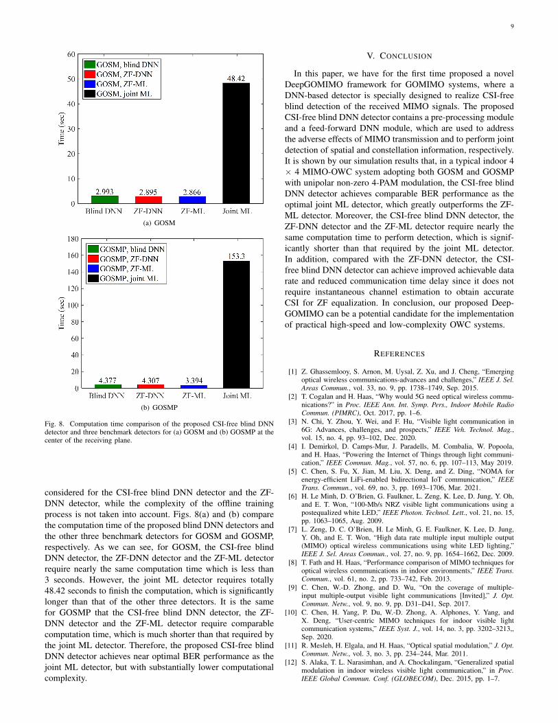
Fig. 8. Computation time comparison of the proposed CSI-free blind DNNdetector and three benchmark detectors for (a) GOSM and (b) GOSMP at thecenter of the receiving plane.
considered for the CSI-free blind DNN detector and the ZF-DNN detector, while the complexity of the offline trainingprocess is not taken into account. Figs. 8(a) and (b) comparethe computation time of the proposed blind DNN detectors andthe other three benchmark detectors for GOSM and GOSMP,respectively. As we can see, for GOSM, the CSI-free blindDNN detector, the ZF-DNN detector and the ZF-ML detectorrequire nearly the same computation time which is less than3 seconds. However, the joint ML detector requires totally48.42 seconds to finish the computation, which is significantlylonger than that of the other three detectors. It is the samefor GOSMP that the CSI-free blind DNN detector, the ZF-DNN detector and the ZF-ML detector require comparablecomputation time, which is much shorter than that required bythe joint ML detector. Therefore, the proposed CSI-free blindDNN detector achieves near optimal BER performance as thejoint ML detector, but with substantially lower computationalcomplexity.
V. CONCLUSION
In this paper, we have for the first time proposed a novelDeepGOMIMO framework for GOMIMO systems, where aDNN-based detector is specially designed to realize CSI-freeblind detection of the received MIMO signals. The proposedCSI-free blind DNN detector contains a pre-processing moduleand a feed-forward DNN module, which are used to addressthe adverse effects of MIMO transmission and to perform jointdetection of spatial and constellation information, respectively.It is shown by our simulation results that, in a typical indoor 4× 4 MIMO-OWC system adopting both GOSM and GOSMPwith unipolar non-zero 4-PAM modulation, the CSI-free blindDNN detector achieves comparable BER performance as theoptimal joint ML detector, which greatly outperforms the ZF-ML detector. Moreover, the CSI-free blind DNN detector, theZF-DNN detector and the ZF-ML detector require nearly thesame computation time to perform detection, which is signif-icantly shorter than that required by the joint ML detector.In addition, compared with the ZF-DNN detector, the CSI-free blind DNN detector can achieve improved achievable datarate and reduced communication time delay since it does notrequire instantaneous channel estimation to obtain accurateCSI for ZF equalization. In conclusion, our proposed Deep-GOMIMO can be a potential candidate for the implementationof practical high-speed and low-complexity OWC systems.
REFERENCES
[1] Z. Ghassemlooy, S. Arnon, M. Uysal, Z. Xu, and J. Cheng, “Emergingoptical wireless communications-advances and challenges,” IEEE J. Sel.Areas Commun., vol. 33, no. 9, pp. 1738–1749, Sep. 2015.
[2] T. Cogalan and H. Haas, “Why would 5G need optical wireless commu-nications?” in Proc. IEEE Ann. Int. Symp. Pers., Indoor Mobile RadioCommun. (PIMRC), Oct. 2017, pp. 1–6.
[3] N. Chi, Y. Zhou, Y. Wei, and F. Hu, “Visible light communication in6G: Advances, challenges, and prospects,” IEEE Veh. Technol. Mag.,vol. 15, no. 4, pp. 93–102, Dec. 2020.
[4] I. Demirkol, D. Camps-Mur, J. Paradells, M. Combalia, W. Popoola,and H. Haas, “Powering the Internet of Things through light communi-cation,” IEEE Commun. Mag., vol. 57, no. 6, pp. 107–113, May 2019.
[5] C. Chen, S. Fu, X. Jian, M. Liu, X. Deng, and Z. Ding, “NOMA forenergy-efficient LiFi-enabled bidirectional IoT communication,” IEEETrans. Commun., vol. 69, no. 3, pp. 1693–1706, Mar. 2021.
[6] H. Le Minh, D. O’Brien, G. Faulkner, L. Zeng, K. Lee, D. Jung, Y. Oh,and E. T. Won, “100-Mb/s NRZ visible light communications using apostequalized white LED,” IEEE Photon. Technol. Lett., vol. 21, no. 15,pp. 1063–1065, Aug. 2009.
[7] L. Zeng, D. C. O’Brien, H. Le Minh, G. E. Faulkner, K. Lee, D. Jung,Y. Oh, and E. T. Won, “High data rate multiple input multiple output(MIMO) optical wireless communications using white LED lighting,”IEEE J. Sel. Areas Commun., vol. 27, no. 9, pp. 1654–1662, Dec. 2009.
[8] T. Fath and H. Haas, “Performance comparison of MIMO techniques foroptical wireless communications in indoor environments,” IEEE Trans.Commun., vol. 61, no. 2, pp. 733–742, Feb. 2013.
[9] C. Chen, W.-D. Zhong, and D. Wu, “On the coverage of multiple-input multiple-output visible light communications [Invited],” J. Opt.Commun. Netw., vol. 9, no. 9, pp. D31–D41, Sep. 2017.
[10] C. Chen, H. Yang, P. Du, W.-D. Zhong, A. Alphones, Y. Yang, andX. Deng, “User-centric MIMO techniques for indoor visible lightcommunication systems,” IEEE Syst. J., vol. 14, no. 3, pp. 3202–3213,,Sep. 2020.
[11] R. Mesleh, H. Elgala, and H. Haas, “Optical spatial modulation,” J. Opt.Commun. Netw., vol. 3, no. 3, pp. 234–244, Mar. 2011.
[12] S. Alaka, T. L. Narasimhan, and A. Chockalingam, “Generalized spatialmodulation in indoor wireless visible light communication,” in Proc.IEEE Global Commun. Conf. (GLOBECOM), Dec. 2015, pp. 1–7.

10
[13] F. Wang, F. Yang, and J. Song, “Constellation optimization under theergodic VLC channel based on generalized spatial modulation,” Opt.Exp., vol. 28, no. 14, pp. 21 202–21 209, Jul. 2020.
[14] K. Wang, “Indoor optical wireless communication system with filters-enhanced generalized spatial modulation and carrierless amplitude andphase (CAP) modulation,” Opt. Lett, vol. 45, no. 18, pp. 4980–4983,Sep. 2020.
[15] C. Chen, X. Zhong, S. Fu, X. Jian, M. Liu, H. Yang, A. Alphones,and H. Y. Fu, “OFDM-based generalized optical MIMO,” J. Lightw.Technol., vol. 39, no. 19, pp. 6063–6075, Oct. 2021.
[16] T. Ozbilgin and M. Koca, “Optical spatial modulation over atmosphericturbulence channels,” J. Lightw. Technol., vol. 33, no. 11, pp. 2313–2323,Jun. 2015.
[17] Y. LeCun, Y. Bengio, and G. Hinton, “Deep learning,” Nature, vol. 521,no. 7553, pp. 436–444, May 2015.
[18] T. Wang, C.-K. Wen, H. Wang, F. Gao, T. Jiang, and S. Jin, “Deeplearning for wireless physical layer: Opportunities and challenges,” Chin.Commun., vol. 14, no. 11, pp. 92–111, Nov. 2017.
[19] H. Lee, I. Lee, T. Q. Quek, and S. H. Lee, “Binary signaling design forvisible light communication: A deep learning framework,” Opt. Exp.,vol. 26, no. 14, pp. 18 131–18 142, Jul. 2018.
[20] X. Lu, C. Lu, W. Yu, L. Qiao, S. Liang, A. P. T. Lau, and N. Chi,“Memory-controlled deep LSTM neural network post-equalizer used inhigh-speed PAM VLC system,” Opt. Exp., vol. 27, no. 5, pp. 7822–7833,Mar. 2019.
[21] H. Yang, A. Alphones, W.-D. Zhong, C. Chen, and X. Xie, “Learning-based energy-efficient resource management by heterogeneous RF/VLCfor ultra-reliable low-latency industrial IoT networks,” IEEE Trans. Ind.Informat., vol. 16, no. 8, pp. 5565–5576, Aug. 2019.
[22] T. Wang, F. Yang, and J. Song, “Deep learning-based detection schemefor visible light communication with generalized spatial modulation,”Opt. Exp., vol. 28, no. 20, pp. 28 906–28 915, Sep. 2020.
[23] Y. Wang and N. Chi, “Demonstration of high-speed 2 × 2 non-imaging MIMO Nyquist single carrier visible light communication withfrequency domain equalization,” J. Lightw. Technol., vol. 32, no. 11, pp.2087–2093, Jun. 2014.
[24] T. Komine and M. Nakagawa, “Fundamental analysis for visible-lightcommunication system using LED lights,” IEEE Trans. Consum. Elec-tron., vol. 50, no. 1, pp. 100–107, Feb. 2004.
[25] I. Tavakkolnia, A. Yesilkaya, and H. Haas, “OFDM-based spatial mod-ulation for optical wireless communications,” in Proc. IEEE GlobecomWorkshops (GC Wkshps), Dec. 2018, pp. 1–6.
[26] C. Chen, L. Zeng, X. Zhong, S. Fu, M. Liu, and P. Du, “Deep learning-aided OFDM-based generalized optical quadrature spatial modulation,”2021. [Online]. Available: https://arxiv.org/abs/2106.12770.
[27] K. Ying, H. Qian, R. J. Baxley, and S. Yao, “Joint optimization ofprecoder and equalizer in MIMO VLC systems,” IEEE J. Sel. AreasCommun., vol. 33, no. 9, pp. 1949–1958, Sep. 2015.
[28] H. Albinsaid, K. Singh, S. Biswas, C.-P. Li, and M.-S. Alouini, “Blockdeep neural network-based signal detector for generalized spatial mod-ulation,” IEEE Commun. Lett., vol. 24, no. 12, pp. 2775–2779, Dec.2020.