deep soil mixing at the jackson lake damgrouting, and jet grouting. the bid documents suggested the...
TRANSCRIPT

1
ASCE Geotechnical and Construction Divisions Special Conference
June 25-29, 1989
DEEP SOIL MIXING AT THE JACKSON LAKE DAM
By Christopher R. Ryan (1) and Brian H. Jasperse (2)
________________________________________________________________ ABSTRACT: The Jackson Lake Dam was constructed in 1917 in the Grand Teton National Park near Jackson, Wyoming. The dam was a hydraulic fill placed on a natural alluvium and outwash foundation. The Bureau of Reclamation (Burec) determined that the dam and its foundation would be susceptible to liquefaction and failure during a potential earthquake; a series of contracts was let to remove and replace the dam with a compacted fill and to improve the dam’s foundation to depths of up to 110 feet (33 meters). After considering a number of options, the Burec selected deep soil mixing (DSM) as the method to improve the subsoils and to install an upstream cut-off wall. A pre-job test section and extensive quality control testing was carried out, particularly related to the strength of the mixed soil. The results are summarized and reported herein. Significant conclusions reached from the testing program include: - DSM samples continue to increase in strength for at least 112 days after placement. - water cement ratio is the key determining factor in final strength, even more important than cement content. - laboratory results run before the project conservatively predicted field results. - wet mix samples generally have lower strengths than cores taken after the column set The DSM method appears to have great promise as a method for creating deep foundations, retaining walls, areal soil improvement and even underwater foundations. A rapid expansion in the application of this technology is likely for the U.S. market.
(1) President, Geo-Con, Inc., P.O. Box 17380, Pittsburgh, PA 15235 (2) Group Mgr., Geo-Con, Inc. P.O. Box 17380, Pittsburgh, PA 15235

2
OUTLINE OF PROJECT Located in the heart of the Grand Teton National Park, just north of Jackson, Wyoming, the lake, with its background of the jagged peaks of the Grand Tetons, is surrounded by some of the most ruggedly beautiful scenery anywhere. First construction on the Jackson Lake Dam dates back to 1911. The initial dam served as an irrigation source. A concrete spillway structure was completed in 1917 and the structure was increased in height two times in subsequent years. The initial structure was an uncompacted hydraulic fill constructed without a core or an underlying cut-off wall. The dam’s foundation consisted of alluvial and outwash deposits overlying a glacial till. The till or a low-plasticity silt was found at depths of 50-100 ft (15-30m) over most of the project. Overlying these zones was a loose combination of gravels and sands with occasional clay and silt layers. In the early 1980’s, studies performed by the U.S. Bureau of Reclamation (Burec) determined that the dam and its foundation would be highly susceptible to failure due to earthquake-induced liquefaction. A determination was made to rebuild the dam and strengthen its foundation. A series of contracts was let to remove the old dam, rehabilitate the spillway structure, and improve the foundation subsoils. This paper concerns one aspect of the contract awarded in April of 1987, namely, to improve the foundation subsoils. An unusual aspect of this project was the latitude granted to the bidding contractors in choosing a construction method. The bid documents described a desired pattern of columns of stabilized soil, but left to the contractor the method of constructing the columns and of quality assurance. A secondary, but significant, aspect of the project was the requirement for construction of an upstream cut-off wall located under the toe of the future embankment. Bid evaluations were to be based on a system that rewarded technical merit with approximately twice the weight of cost savings. Early in the bid process, the competing contractors determined that technical points outweighed almost all cost considerations, so great emphasis was placed on the system chosen, and the degree to which quality could be assured. SELECTION OF TECHNIQUE Numerous deep soil improvement technologies were considered for use at this project. These included sand compaction piles, stone columns, compaction grouting, and jet grouting. The bid documents suggested the use of compaction piles or jet grouting, both of which had been the subject of test programs at the site. There were, however, significant specification requirements that made any of these techniques impractical or technically undesirable, especially in the face of the technical weight given to bid proposals. These included, for the soil improvement portion of the work, the following provisions:
3
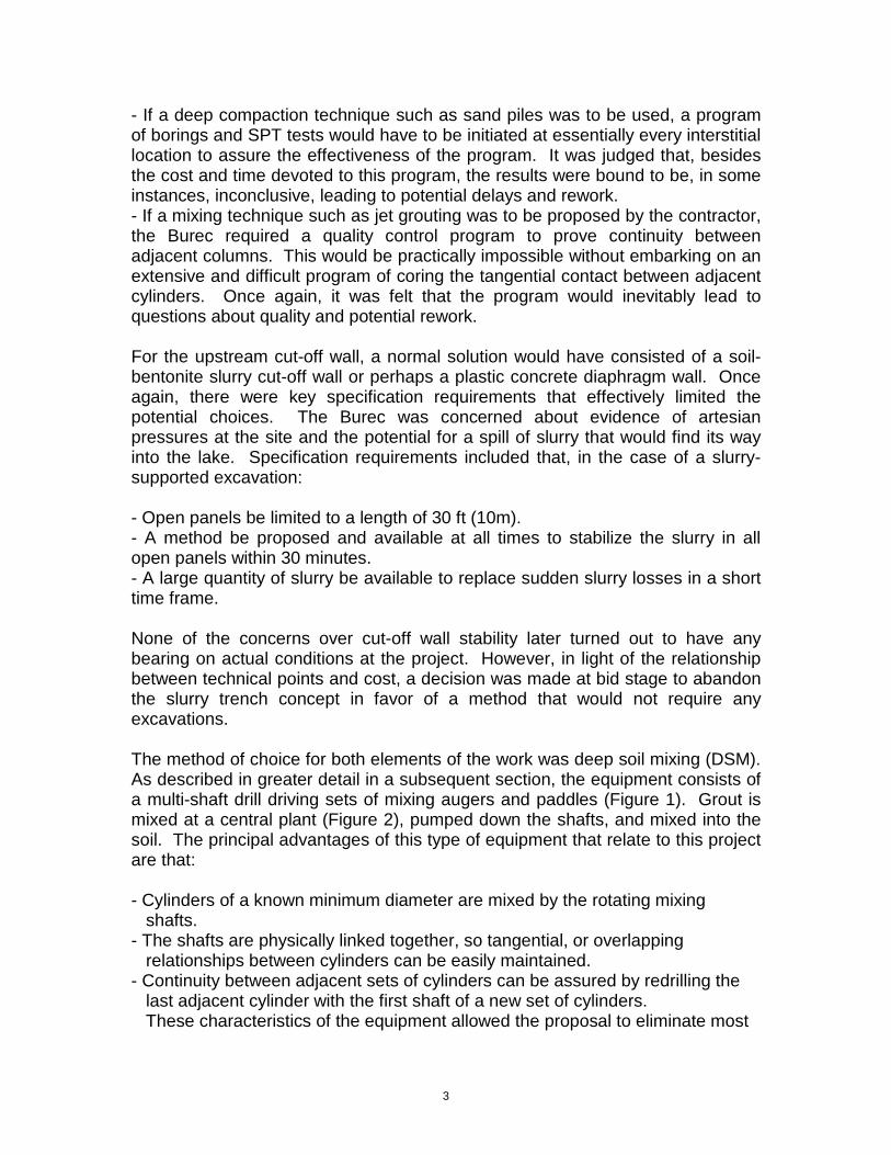
- If a deep compaction technique such as sand piles was to be used, a program of borings and SPT tests would have to be initiated at essentially every interstitial location to assure the effectiveness of the program. It was judged that, besides the cost and time devoted to this program, the results were bound to be, in some instances, inconclusive, leading to potential delays and rework. - If a mixing technique such as jet grouting was to be proposed by the contractor, the Burec required a quality control program to prove continuity between adjacent columns. This would be practically impossible without embarking on an extensive and difficult program of coring the tangential contact between adjacent cylinders. Once again, it was felt that the program would inevitably lead to questions about quality and potential rework. For the upstream cut-off wall, a normal solution would have consisted of a soil-bentonite slurry cut-off wall or perhaps a plastic concrete diaphragm wall. Once again, there were key specification requirements that effectively limited the potential choices. The Burec was concerned about evidence of artesian pressures at the site and the potential for a spill of slurry that would find its way into the lake. Specification requirements included that, in the case of a slurry-supported excavation: - Open panels be limited to a length of 30 ft (10m). - A method be proposed and available at all times to stabilize the slurry in all open panels within 30 minutes. - A large quantity of slurry be available to replace sudden slurry losses in a short time frame. None of the concerns over cut-off wall stability later turned out to have any bearing on actual conditions at the project. However, in light of the relationship between technical points and cost, a decision was made at bid stage to abandon the slurry trench concept in favor of a method that would not require any excavations. The method of choice for both elements of the work was deep soil mixing (DSM). As described in greater detail in a subsequent section, the equipment consists of a multi-shaft drill driving sets of mixing augers and paddles (Figure 1). Grout is mixed at a central plant (Figure 2), pumped down the shafts, and mixed into the soil. The principal advantages of this type of equipment that relate to this project are that: - Cylinders of a known minimum diameter are mixed by the rotating mixing shafts. - The shafts are physically linked together, so tangential, or overlapping relationships between cylinders can be easily maintained. - Continuity between adjacent sets of cylinders can be assured by redrilling the last adjacent cylinder with the first shaft of a new set of cylinders. These characteristics of the equipment allowed the proposal to eliminate most

4
of the time-consuming and potentially confusing quality control work required by the specifications. Secondary advantages that related to the project were that; - The full-length treatment from the surface to the bottom eliminates the need for a large portion of a “shallow” soil improvement zone that was to have been completed using dynamic compaction to a depth of about 30 ft (10m). - Since material is never removed from the mixing zone, the method is not affected by artesian conditions, so all of the concerns over the cut-off wall were not applicable. For all of these reasons, the Burec assigned the highest technical weight to the DSM proposal and it was eventually accepted and incorporated into the project.
Figure 1. Deep Soil Mixing Drill Rig
HISTORY OF DEEP SOIL MIXING As used in this paper, “DSM” or “deep soil mixing” is a generic term for a process that had its roots in the 1950’s and which has undergone considerable
5
development and refinement in the years since. An early U.S. patent (6) describes a Mixed in Place pile process that was used on several projects. In the late 1960’s and early 1970’s the Swedes used a mixed-in-place lime stabilization process in certain of their quick clays (1, 2). Significant advances were made by several Japanese manufacturers that mounted multiple shaft augers to improve productivity (10). Numerous projects were completed, some of which have been documented in the U.S. literature (3, 4, 7, 11). Equipment used at the Jackson Lake project was manufactured to the specification of one of these firms (9). Recent advances on the American front have included construction of larger, more versatile equipment and the use of sophisticated instrumentation to coordinate grout flows with penetration depth. Another American evolution of the technique is in its application to site remediation of hazardous waste spills. Applications have included containments (5) and in-situ fixation (8). Applications in the planning or design stage to date include underwater soil improvement, retaining walls, foundation support for structures, and many more.
Figure 2. Central Grout Mix Plant
DESCRIPTION OF SOIL IMPROVEMENT WORK To control liquefaction in case of an earthquake of a magnitude of up to 6 on the Richter scale, a series of soilcrete cells (Figure 3) were constructed using DSM on the upstream and downstream side of the dam extending from 20 ft (6m) outside of the embankment toe to 30 ft (9m) inside the embankment toes.

6
Figure 3. Soil Improvement Pattern - Plan
In addition to foundation densification treatment, the Burec required a cut-off wall along the entire upstream toe of the dam to a depth of 20 ft (6m) into the silt layer. the cut-off wall was also constructed using DSM. The length of the treatment zone was about 1,900 ft (580m) for the soil improvement work and 4,000 ft (1200m) for the cut-off wall. The theory behind the soilcrete cells is that, in the event of liquefaction, the soils would be contained in the cells thereby preventing a shear failure in the foundation that would cause a collapse of the embankment. The Burec had a requirement of 200-psi (1380 kPa) shear strength for the soilcrete columns. To prevent a failure underneath the cells, it was required that the cells extend a minimum of 10ft (3m) into the till or silt layer which would not liquefy (Figure 4).

7
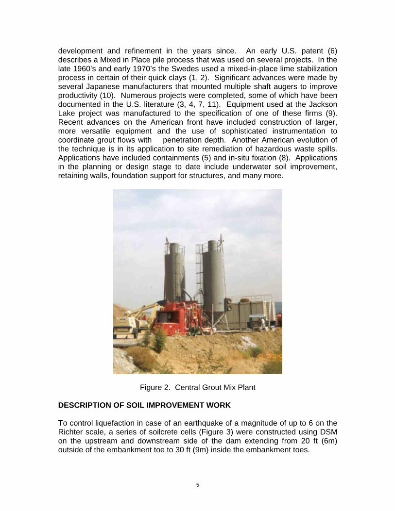
Figure 4. Work Plan – Cross Section SOIL MIXING EQUIPMENT The equipment for the DSM cell work consisted of soil mixing rigs and grout plant. The base machine for the rig was a crane fitted with pile driving leads. A large electric motor with guide fitted to the leads was pulled up and down by the crane drum. The electric motor had a large shaft which fitted into a gearbox; from the bottom of the gearbox extended two drive shafts on 36 in. (915mm) centers which turned the two tangent 36 in (915mm) diameter-mixing tools. The mixing tools were hollow-stemmed shafts to which were welded a series of discontinuous auger flights. Between the flighting, thick flat beater bars were attached. At the bottom of each shaft was an earth auger cutting head. As drilling began, the cutting heads penetrated the soil as grout was pumped through the hollow stem and out the tip of the shaft. The discontinuous flight would loosen and break up the soil but would not lift it out of the hole as continuous flighting would, but rather lifted the soil t the flat bars which mixed like a pugmill and blended the grout with the soil into a homogenous soilcrete column (Figure 5). The grout would set in a few hours, eventually hardening into a coreable soilcrete that could be cored (Figure 6).

8
Figure 5. Soil Mixing in Progress
CUT-OFF WALL EQUIPMENT The cut-off wall was required to have a minimum thickness of 24 in. (610mm). To meet this requirement, a three shaft-mixing auger was built with 34 in. (864mm) mixing flights. The shafts were on 24 in. (610mm) centers yielding a 24 in. (610mm) thick wall at the overlap points. The equipment to install the cut-off wall was basically the same as far as the base crane and support equipment. A different gearbox that would dive a 3 shaft-mixing auger was attached to the electric motor. The cut-off wall was installed by using a primary-secondary type drill pattern. QUALITY CONTROL The Bureau of Reclamation had the following requirements for the soilcrete columns for both cell construction and cut-off wall work: - Columns of required size for full length - Columns extending to required depth - 200 psi (1380kPa) shear strength - Well-mixed soilcrete columns - Uniform distribution of grout in the columns - Verticality tolerance of 1%. - Minimum 24 in. (610mm) overlap for cut-off wall columns.
9
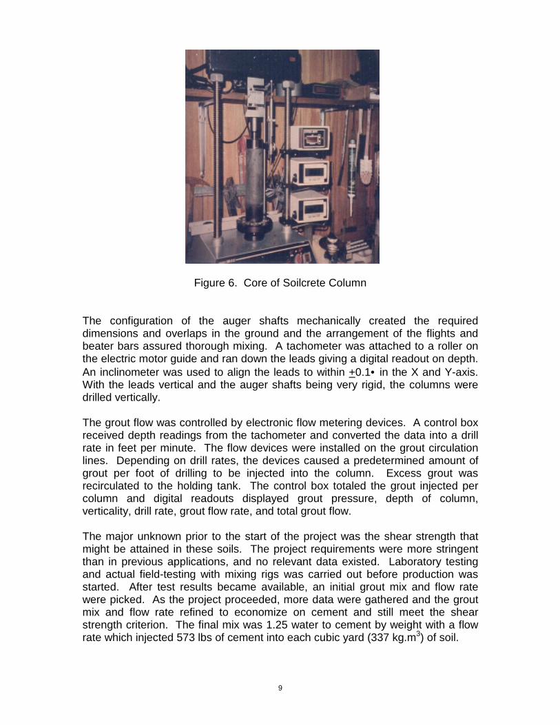
Figure 6. Core of Soilcrete Column
The configuration of the auger shafts mechanically created the required dimensions and overlaps in the ground and the arrangement of the flights and beater bars assured thorough mixing. A tachometer was attached to a roller on the electric motor guide and ran down the leads giving a digital readout on depth. An inclinometer was used to align the leads to within +0.1• in the X and Y-axis. With the leads vertical and the auger shafts being very rigid, the columns were drilled vertically. The grout flow was controlled by electronic flow metering devices. A control box received depth readings from the tachometer and converted the data into a drill rate in feet per minute. The flow devices were installed on the grout circulation lines. Depending on drill rates, the devices caused a predetermined amount of grout per foot of drilling to be injected into the column. Excess grout was recirculated to the holding tank. The control box totaled the grout injected per column and digital readouts displayed grout pressure, depth of column, verticality, drill rate, grout flow rate, and total grout flow. The major unknown prior to the start of the project was the shear strength that might be attained in these soils. The project requirements were more stringent than in previous applications, and no relevant data existed. Laboratory testing and actual field-testing with mixing rigs was carried out before production was started. After test results became available, an initial grout mix and flow rate were picked. As the project proceeded, more data were gathered and the grout mix and flow rate refined to economize on cement and still meet the shear strength criterion. The final mix was 1.25 water to cement by weight with a flow rate which injected 573 lbs of cement into each cubic yard (337 kg.m3) of soil.

10
TECHNICAL RESULTS A great deal of data was obtained from the project on soilcrete columns. Typically, “wet samples” were taken from the columns by inserting a sampling device into the columns immediately after mixing and retrieving samples from various depths. Over 2,000 of these “wet samples” were made, cured, and broken for compressive strength or shear strength information. About 70 core holes were made and about 150 core samples were broken to correlate actual in-column strength with wet samples. There were two important findings. The first was that up to 112 days and maybe further, there are significant strength gains in the soilcrete. The strength gains from 7 days to 28 days and from 28 days to 56 days are each 100%. From 6 days to 112 days of age, there is a 40 to 50% gain in strength and the curves from 7 to 112 days still have not completely flattened out (Figure 7). Secondly, the water/cement ration, rather than the amount of cement injected, has the most effect on the strength of the soilcrete. In general, columns installed using more cement but the same water/cement ratio showed insignificant strength gain, particularly considering the economics of cement expenditures. However, columns installed using the same cement amount with lower water/cement ratios had significant strength gains (Figure 8). While significant laboratory testing was done at an early stage in the project, one of the big questions was how lab data would relate to field data. Despite all of the data generated on this project, it was difficult to locate sets of data that corresponded with respect to area of the site, cement/water ratio, and cement content. Figure 9 presents one set of data that was comparable. Field wet samples yielded results substantially higher than laboratory samples, probably because some waster is squeezed out of the mix before it sets. In addition to the program of wet sampling, which was the primary quality control measure taken; a series of core borings was used to take samples from the set-up columns. Figure 10 shows that core strengths were generally somewhat higher than were samples taken nearby during the work. This is probably because of excellent insitu curing conditions which include high pressure and a cool, moist environment.

11

12

13
Shear strength was determine from triaxial and direct shear tests to be about one third of compressive strength, so the specified shear strength of 200 psi (1380kPa) corresponded to unconfined compressive strength of 600 psi (4140 kPa). Taking into account strength gain over time, core strength versus wet sample strength, and shear strength versus compressive strength, it was determined that a 7 day wet sample compressive strength of 125 to 150 psi (860-1030 kPa) would yield a fully cured column of 200 psi (1380 kPa) shear strength. This relationship provided a quick and easy way to be assured that the DSM work would meet strength criteria by testing wet samples for compressive strength after seven days. CONCLUSION At the Jackson Lake project, deep soil mixing provided an economical, reliable way of satisfying a difficult set of technical parameters and meeting a tight project work schedule. Obviously, much is yet to be learned about DSM strength parameters at other sites with differing soil conditions. It is apparent, however, that high quality, high strength columns can be constructed using DSM. The different applications that could be used are numerous and the technique appears to have a solid future in the geotechnical construction industry. ACKNOWLEDGMENTS The authors would like to thank Shuichi Kagami of Taisei Corporation for his invaluable assistance in collecting and collating data used in this paper. REFERENCES
1. BB Broms & P Boman, Lime Columns – A New Foundation Method, ASCE J.Geot.Eng.(ASCE). 105 (4), 1977, 539-556.
2. BB Broms & P Boman, Stabilization of Soil with Lime Columns –Design Handbood, Royal Institute of Technology, Department of Soil and Rock Mechanics, Stockholm, Feb. 1978. 3. ENR, Weak Seabed Strata Yields Strong Support, Mar 10, 1983, 30-31. 4. P Hann, Taipei Untangles Its Rail Lines, ENR, Feb 13, 1986, 41-42. 5. BH Jasperse & CR Ryan, Geotech Import: Deep Soil Mixing, Civil Engineering, Dec 1987, 66-68. 6. NL Liver, Mixed In Place Pile Patent, US Patent No. 3,023,585, Filed Nov 26, 1956. 7. M Ralton, Dam Rebuilt to Save It From Quakes, ENR, Sep17, 1987,46-47. 8. S Sawyer, Site Demonstration Report – In Situ Stabilization/Solidification –
Hialeah, FL, EERU Contract No. 68-03-3255 USEPA, Cincinnati, Nov 1988.

14
9. Seiko Kogyo /Co., Ltd., Soil-Cement /Diaphragm Wall, Seiko Kogyo Co., Ltd., Osaka, 1983. 10. Takenaka Komuten, Deep Mixing Method Using Cement Slurry As Hardening Agent, TakenakaKomuten, Tokyo, Apr 1985. 11. N Usui, Japanese Start Construction on Kansai Seawall, ENR, Jul 2, 1987, 24.