decoupling identification and physical parameter estimation...
TRANSCRIPT
Extended Summary 本文は pp.669–677
Decoupling Identification and Physical Parameter Estimationfor Serial Two-Link Two-Inertia System
Junji Oaki Student Member (Keio University and Toshiba Corporation, [email protected])
Shuichi Adachi Member (Keio University, [email protected])
Keywords: multivariable identification, subspace identification method, SCARA-type robot, elastic joint, two-inertia resonant sys-tem, accelerometer
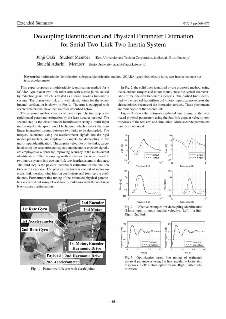
This paper proposes a multivariable identification method for aSCARA-type planar two-link robot arm with elastic joints causedby reduction gears, which is treated as a serial two-link two-inertiasystem. The planar two-link arm with elastic joints for the exper-imental verification is shown in Fig. 1. The arm is equipped withaccelerometers that have the two roles described below.
The proposed method consists of three steps. The first step is therigid model parameter estimation by the least-squares method. Thesecond step is the elastic model identification using a multi-inputmulti-output state space model technique, which enables the non-linear interaction torques between two links to be decoupled. Thetorques, calculated using the accelerometer signals and the rigidmodel parameters, are employed as inputs for decoupling in themulti-input identification. The angular velocities of the links, calcu-lated using the accelerometer signals and the motor encoder signals,are employed as outputs for improving accuracy in the multi-outputidentification. The decoupling method divides the serial two-linktwo-inertia system into two one-link two-inertia systems in this step.The third step is the physical parameter estimation of the one-linktwo-inertia systems. The physical parameters consist of motor in-ertias, link inertias, joint-friction coefficients and joint-spring coef-ficients. Furthermore fine tuning of the estimated physical parame-ters is carried out using closed-loop simulations with the nonlinearleast-squares optimization.
Fig. 1. Planar two-link arm with elastic joints
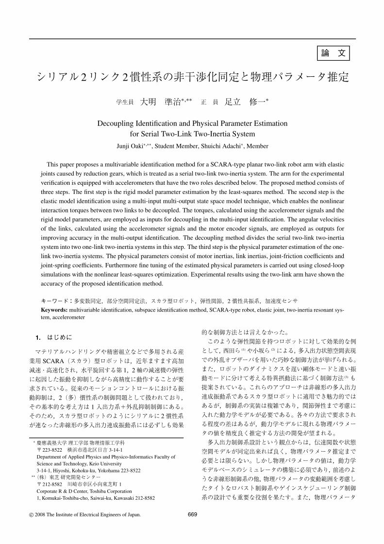
In Fig. 2, the solid lines identified by the proposed method, usingthe calculated torques and motor inputs, show the typical character-istics of the one-link two-inertia systems. The dashed lines identi-fied by the method that utilizes only motor inputs cannot express thecharacteristics because of the interaction torques. These phenomenaare remarkable at the second link.
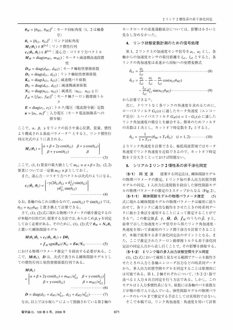
Figure 3 shows the optimization-based fine tuning of the esti-mated physical parameters using the first-link angular velocity stepresponses of the real arm and simulation. More accurate parametershave been obtained.
Fig. 2. Effective examples for decoupling identification(Motor input to motor angular velocity). Left: 1st link.Right: 2nd link
Fig. 3. Optimization-based fine tuning of estimatedphysical parameters using 1st link angular velocity stepresponses. Left: Before optimization. Right: After opti-mization
– 15 –
論 文
シリアル2リンク2慣性系の非干渉化同定と物理パラメータ推定
学生員 大明 準治∗,∗∗ 正 員 足立 修一∗
Decoupling Identification and Physical Parameter Estimationfor Serial Two-Link Two-Inertia System
Junji Oaki∗,∗∗, Student Member, Shuichi Adachi∗, Member
This paper proposes a multivariable identification method for a SCARA-type planar two-link robot arm with elastic
joints caused by reduction gears, which is treated as a serial two-link two-inertia system. The arm for the experimental
verification is equipped with accelerometers that have the two roles described below. The proposed method consists of
three steps. The first step is the rigid model parameter estimation by the least-squares method. The second step is the
elastic model identification using a multi-input multi-output state space model technique, which enables the nonlinear
interaction torques between two links to be decoupled. The torques, calculated using the accelerometer signals and the
rigid model parameters, are employed as inputs for decoupling in the multi-input identification. The angular velocities
of the links, calculated using the accelerometer signals and the motor encoder signals, are employed as outputs for
improving accuracy in the multi-output identification. The decoupling method divides the serial two-link two-inertia
system into two one-link two-inertia systems in this step. The third step is the physical parameter estimation of the one-
link two-inertia systems. The physical parameters consist of motor inertias, link inertias, joint-friction coefficients and
joint-spring coefficients. Furthermore fine tuning of the estimated physical parameters is carried out using closed-loop
simulations with the nonlinear least-squares optimization. Experimental results using the two-link arm have shown the
accuracy of the proposed identification method.
キーワード:多変数同定,部分空間同定法,スカラ型ロボット,弾性関節,2慣性共振系,加速度センサ
Keywords: multivariable identification, subspace identification method, SCARA-type robot, elastic joint, two-inertia resonant sys-tem, accelerometer
1. はじめに
マテリアルハンドリングや精密組立などで多用される産業用 SCARA(スカラ)型ロボットは,近年ますます高加
減速・高速化され,水平旋回する第 1,2軸の減速機の弾性に起因した振動を抑制しながら高精度に動作することが要求されている。従来のモーションコントロールにおける振動抑制は,2(多)慣性系の制御問題として扱われており,
その基本的な考え方は 1入出力系+外乱抑制制御にある。そのため,スカラ型ロボットのようにシリアルに 2慣性系が連なった非線形の多入出力連成振動系には必ずしも効果
∗ 慶應義塾大学理工学部物理情報工学科〒223-8522 横浜市港北区日吉 3-14-1Department of Applied Physics and Physico-Informatics Faculty ofScience and Technology, Keio University3-14-1, Hiyoshi, Kohoku-ku, Yokohama 223-8522
∗∗(株)東芝研究開発センター〒212-8582 川崎市幸区小向東芝町 1Corporate R & D Center, Toshiba Corporation1, Komukai-Toshiba-cho, Saiwai-ku, Kawasaki 212-8582
的な制御方法とは言えなかった。このような弾性関節を持つロボットに対して効果的な例
として,西田ら (1)や小坂ら (2)による,多入出力状態空間表現での外乱オブザーバを用いた巧妙な制御方法が挙げられる。また,ロボットのダイナミクスを遅い剛体モードと速い振動モードに分けて考える特異摂動法に基づく制御方法 (3) も
提案されている。これらのアプローチは非線形の多入出力連成振動系であるスカラ型ロボットに適用でき魅力的ではあるが,制御系の実装は複雑であり,関節弾性まで考慮に入れた動力学モデルが必要である。各々の方法で要求され
る程度の差はあるが,動力学モデルに現れる物理パラメータの値を精度良く推定する方法の開発が望まれる。多入出力制御系設計という観点からは,伝達関数や状態空間モデルが同定出来れば良く,物理パラメータ推定まで
必要とは限らない。しかし物理パラメータの値は,動力学モデルベースのシミュレータの構築に必須であり,前述のような非線形制御系の他,物理パラメータの変動範囲を考慮し
たタイトなロバスト制御系やゲインスケジューリング制御系の設計でも重要な役割を果たす。また,物理パラメータ
c© 2008 The Institute of Electrical Engineers of Japan. 669

の経年変化を監視することでロボットの品質保証もできる。ここでいう物理パラメータとは,各軸の慣性やバネ係数,
摩擦係数を指している。慣性については,昨今の 3 次元CAD によれば,かなり正確な値が計算可能である。しかし,そのような詳細なデータが入手できるとは限らないので,組立後に動作させて得た時系列データから推定する必
要がある。バネ係数については,減速機メーカーから提供されるカタログ (4) 中のデータが参考にはなるが,ベアリング等の特性も含まれてくるため,組立後の時系列データから推定すべきものである。摩擦係数については,当然のこ
とながら,組立後の時系列データからしか推定できない。さて,時系列データからの 1入出力 2慣性系の物理パラメータ推定については,例えば,粟屋ら (5)の方法が使える。しかし,スカラ型ロボットのようなシリアル 2リンク 2慣
性系では,連成振動の影響が出るため誤差を生じる (6)。時系列データから多リンク剛体関節モデルの物理パラメータの値を推定する方法 (7) については従来からさまざま研究されてきたが,周波数応答を見ながらの手作業 (2) なしに弾
性関節モデルまで拡張したものはほとんど見あたらない。本稿では,前述のようなシリアル 2リンク 2慣性系に対して,部分空間法に基づく多入出力状態空間モデル同定法を応用した第 1,2リンクの非干渉化同定法と,各リンク
の慣性やバネ係数,摩擦係数といった物理パラメータの値を推定する方法を提案する。本同定法は,各リンク上に搭載した加速度センサ信号を同定出力だけでなく,同定入力
にも利用することに特徴がある。そして,多入力による同定時のリンク間非干渉化達成と,多出力による同定精度向上をねらっている。この非干渉化によって,2つの 1リンク 2慣性系の同定問題に帰着させているのがポイントであ
る。そして,同定された 1リンク 2慣性系の式から物理パラメータの値を推定する。さらに,閉ループシミュレーションベースの非線形最適化手法に基づいて物理パラメータ推定のファインチューニングも試みた。バネ係数や摩擦係数
は,厳密には非線形特性を持つが,本稿は,実機の波形に出来るだけ良く合い,かつ,制御系設計に使いやすいモデルを得るために,これらを定数として推定する立場をとる。以下の章では,本稿で対象とするシステムと提案する方
法を述べた後,水平旋回型 2リンクアームの実機で有効性を検証した結果を示す。
2. 対象とするシステム
本稿で制御対象とするのは,Fig. 1に示すような水平旋回型の 2リンクアーム(各リンクの長さ 0.325 m)である。各軸を駆動するDCモータ(第 1軸 500 W,第 2軸 300 W)
は各リンク上に配置され,バネ要素として振る舞うハーモニックドライブ R© 減速機(減速比 1/50)が直結されている。これは,スカラ型ロボットの第 1,2軸を模擬しており,1リンク 2慣性系が直列に 2つ配置されているので,本
稿ではシリアル 2リンク 2慣性系と呼ぶ。第 1,2軸の駆動系は全く同じ構造をしているが,第 2軸は並進運動もす
Fig. 1. Planar two-link arm with elastic joints
るので,回転運動だけの第 1軸とは異なる複雑な連成振動特性を示すのが特徴である。ハーモニックドライブ R©については入力軸周波数の 2倍で脈動し,これが,2慣性系の固有周波数を励起すると激しい振動を起こすことが知られている (8),しかし,脈動自体は制御できないため,本稿で
は,固有周波数におけるゲインを抑制制御するためのモデルに必要な慣性やバネ係数,摩擦係数などの物理パラメータ推定を取り扱う。第 2リンク先端には 1枚 1 kgの円盤を 5枚取り付けて
あり,5∼0 kgの範囲で手先負荷を変化できる。各モータには,モータ回転角度計測用エンコーダ(8192 pulse)が内蔵され,各リンク上には,並進加速度計測用加速度センサ(帯域 300 Hz)が搭載されている。この並進加速度の座標変換
によってリンク毎の回転角加速度を得ると共に,後述するエンコーダ差分信号との融合演算によって,リンク毎の回転角速度を得る。リンク上には,角速度計測用レートジャイロ(帯域 5 Hz)も搭載されているが,今回は並進加速度
信号から計算した角速度の精度確認だけに用いている。以上で得た角加速度信号は多入力による非干渉化同定達成のために,角速度信号については多出力による同定精度向上のために利用される。なお,アーム制御や同定用デー
タ収集には,リアルタイム LinuxPCを用いている。
3. シリアル 2リンク 2慣性系の動力学モデル
シリアル 2リンク 2慣性系の動力学モデル (1) (2) は,次の
ようなモータ側とリンク側の 2組の式で与えられる。
MM θM + DM θM + f Msgn(θM)
= Eu − NG[KG(NGθM − θL) + DG(NG θM − θL)]
· · · · · · · · · · · · · · · · · · · · (1)
ML(θL)θL + cL(θL, θL) + DLθL
= KG(NGθM − θL) + DG(NGθM − θL) · · · · · · · · · · · (2)
ただし,
670 IEEJ Trans. IA, Vol.128, No.5, 2008
2リンク 2慣性系の非干渉化同定
θM = [θM1, θM2]T:モータ回転角度(1,2は軸番号)
θL = [θL1, θL2]T:リンク回転角度
ML(θL) ∈ R2×2:リンク慣性行列cL(θL, θL) ∈ R2×1:遠心力・コリオリ力ベクトルMM = diag(mM1, mM2):モータ+減速機高速段慣
性DM = diag(dM1, dM2):モータ軸粘性摩擦係数DL = diag(dL1, dL2):リンク軸粘性摩擦係数
KG = diag(kG1, kG2):減速機バネ係数DG = diag(dG1, dG2):減速機減衰係数NG = diag(nG1, nG2):減速比(nG1,nG2 ≤ 1)f M = [ fM1, fM2]T:モータ軸クーロン動摩擦トル
クE = diag(e1, e2):トルク/電圧(電流指令値)定数
u = [u1, u2]T:入力電圧(モータ電流制御系への指令値)
ここで,α,β,γをリンクの長さや重心位置,質量,慣性より構成される基底パラメータ (7) とすると,リンク慣性行
列は次式のように表される。
ML(θL) =
⎡⎢⎢⎢⎢⎢⎣α + β + 2γ cos(θL2) β + γ cos(θL2)
β + γ cos(θL2) β
⎤⎥⎥⎥⎥⎥⎦
· · · · · · · · · · · · · · · · · · · · (3)
ここで,(1, 1)要素の最大値としてmL1 ≡ α+ β+ 2γ,(2, 2)
要素については一定値mL2 ≡ βとしておく。また,遠心力・コリオリ力ベクトルは次式のようになる。
cL(θL, θL) =
⎡⎢⎢⎢⎢⎢⎣−γ(2θL1θL2 + θ
2L2) sin(θL2)
γθ 2L1 sin(θL2)
⎤⎥⎥⎥⎥⎥⎦
· · · · · · · · · · · · · · · · · · · · (4)
なお,各軸のねじれは微小なので,cos(θL2)や sin(θL2)では,θL2 = nG2θM2 と置き換えて計算できる。
さて,(1),(2)式に現れる物理パラメータの値を推定するのが本稿の目的だが,提案する方法では,あらかじめ β, γを同定しておく必要がある。そのために,(1),(2)式で θM = NGθL
と置いた剛体関節モデル
M(θL)θL + cL(θL, θL) + DθL
+ f M sgn(θM)/NG = Eu/NG · · · · · · · · · · ·(5)
における物理パラメータ推定 (7) を経由する必要がある。ここで,M(θL),Dは,次式で表される剛体関節モデルとしての慣性行列と粘性摩擦係数行列である。
M(θL)
=
⎡⎢⎢⎢⎢⎢⎣α + β + 2γ cos(θL2) + mM1/n2
G1 β + γ cos(θL2)
β + γ cos(θL2) β + mM2/n2G2
⎤⎥⎥⎥⎥⎥⎦
· · · · · · · · · · · · · · · · · · · · (6)
D = diag(dL1 + dM1/n2G1, dL2 + dM2/n
2G2) · · · · · · · · (7)
なお,以上では小坂ら (2)によって指摘されている第2軸の
モータロータの並進運動成分については,影響は小さいと見なし含めなかった。
4. リンク状態変数計測のための信号処理
第 1,2リンク上の加速度センサ信号を a1,a2 とし,各
軸からの加速度センサの取付距離を la1,la2 とすると,各リンクの角加速度は並進から回転への座標変換式
θL1 =a1
la1· · · · · · · · · · · · · · · · · · · · · · · · · · · · · · · · · · · · · · · (8)
θL2 =a2
la2− a1
la1− a1
la2cos(nG2θM2)
− la1
la2θ 2
L1 sin(nG2θM2) · · · · · · · · · · · · · · · · · · · · · · (9)
から計算できる (9)。
次に,ドリフトなく各リンクの角速度を求めるために,ローパスフィルタGL(s)に通したモータ角速度(エンコーダ差分)とハイパスフィルタ GH(s) = 1 − GL(s)に通したリンク角加速度の積分とを融合する。簡単のためフィルタ
の次数は 1次とし,カットオフ時定数を TV とすると,
θLi =1
1 + TV s(θMi + TV θLi) (i = 1, 2) · · · · · · · · · (10)
よりリンク角速度を計算できる。極低周波帯域ではモータ角速度でリンク角速度を近似できるので,カットオフ時定
数を十分大きくとっておけば問題ない。
5. シリアル 2リンク 2慣性系の非干渉化同定
〈5・1〉 同 定 法 提案する同定法は,剛体関節モデルの物理パラメータの推定,1リンク毎の多入出力状態空間モデルの同定,1入出力伝達関数を経由した弾性関節モデ
ルの物理パラメータの推定の 3ステップからなる(Fig. 2)。〈5・1・1〉 剛体関節モデルの物理パラメータ推定 (5)
式に現れる剛体関節モデルの物理パラメータは線形に括り出せて,各リンクに適当な動作をさせたときの時系列データに最小 2乗法を適用することによって推定することができる (7)。この推定値 β,γ,M,D, f M のうちの β,γと,
前章で示した加速度センサ信号から得たリンク角加速度・角速度を用いて非線形のリンク間干渉力を計算できることが,本稿で提案する非干渉化同定法のポイントとなる。ま
た,ここで推定されたクーロン動摩擦トルクも非干渉化同定法の同定入力から差し引くことで,その影響を排除する。〈5・1・2〉 1リンク毎の多入出力状態空間モデル同定(1),(2)式において線形と見なせる範囲でアームを動作させたときの入力と各軸エンコーダ出力などの時系列データから,多入出力状態空間モデルを同定することは原理的に
は可能である。第 1,2軸それぞれについて,〈5・2・2〉節で述べる 1入力 4出力同定を行う方法である。しかし,このモデルは 1入力多慣性系になり,係数には各軸のバネ係数などが積の形で入り込んでいる。弾性関節モデルの物理パラ
メータのレベルまで推定する手法としては実用的ではない。そこで本稿では,リンク角加速度・角速度を用いて計算
電学論 D,128 巻 5 号,2008 年 671
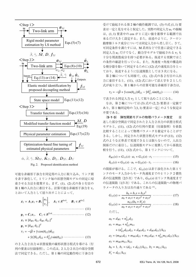
Fig. 2. Proposed identification method
可能な非線形干渉力を同定用の入力に取り込み,リンク間
を非干渉化して,1リンク毎の状態空間モデルの同定に帰着させる方法を提案する。まず,(1),(2)式の各 1行目の第 1軸の入出力に着目する。計算可能な非線形干渉力を τ1
とおいて入力として括り出すことによって,
x1 = A1x1 + B1
⎡⎢⎢⎢⎢⎢⎣u1
τ1
⎤⎥⎥⎥⎥⎥⎦ , A1 ∈ R4×4, B1 ∈ R4×2
· · · · · · · · · · · · · · · · · · (11)
y1 = C1x1, C1 ∈ R2×4 · · · · · · · · · · · · · · · · · · · · · · · (12)
x1 ≡ [θM1 θL1 θM1 θL1]T
y1 ≡ [θM1 θL1]T
τ1 = −(β + γ cos(θL2))θL2
+ γ(2θL1θL2 + θ2L2) sin(θL2) · · · · · · · · · · · · · · · (13)
の 2入力 2出力 4状態変数の線形状態方程式を導ける(行
列の要素は付録参照)。この式は,2入力 2出力の部分空間法で同定できる。ただし,第 1軸の同定動作時に干渉力を
受けて励起される第 2軸の動作範囲では,(3)の式 (1, 1)要素は一定と見なせると仮定した。実際の同定入力 u1の振幅
は,(1, 1)要素中の cos が 1に近い値を推移する範囲で出来るだけ大きく設定する。また,前述のように,クーロン動摩擦トルク成分については同定入力から差し引く。さて,可同定条件を満たすには,M系列などで任意に設定できる
同定入力 u1 だけでなく,動力学モデルで励起される τ1 も十分な周波数成分を持つ必要がある。後述する実験ではこの条件の確認を行っている。また,角速度→角度の構造的な積分器を除いて同定するために (12)式の速度出力をとっ
ており,後述するように伝達関数としては 3次になる。第 2軸についても同様で,(1),(2)式の各 2行目の入出力に着目すると,(11),(12)式において添え字を 2とした式が成り立つ。第 1軸からの計算可能な非線形干渉力は,
τ2 = −(β + γ cos(θL2))θL1 − γθ 2L1 sin(θL2) · · · · · · · (14)
で表される同定入力 τ2 として取り込むことになる。なお,第 2軸については (3)式の (2, 2)要素は一定値であり,第 1軸同定時の「(1, 1)要素は一定」のような仮定は不要である。〈5・1・3〉 弾性関節モデルの物理パラメータ推定 前述した部分空間法で同定された 2入力 2出力の状態方程式モデルと,(11),(12)式の行列の要素(付録参照)を係数比較することによって物理パラメータを推定することがで
きる。しかし,同定された状態方程式モデルが (11),(12)
式のような正準系で実現できるとは限らないので,入出力関係だけに着目し,伝達関数モデルに変換してから係数比
較を行う。(11),(12)式から,第 1リンクについて,
θM1(s) = G11(s) · u1 +G12(s) · τ1 · · · · · · · · · · · · · · (15)
θL1(s) = G21(s) · u1 +G22(s) · τ1 · · · · · · · · · · · · · · (16)
の関係が導ける。ここで,G11(s)は非干渉化された第 1リンクのモータ入力からモータ角速度までの 1リンク 2慣性系の伝達関数(2/3次)であり,G21(s)はリンク角速度まで
の伝達関数(1/3次)である。これらの伝達関数への物理パラメータの入り方は次の通りである (10)。
G11(s) =b0 + b1s + b2s2
a0 + a1s + a2s2 + a3s3· · · · · · · · · · · · · · (17)
G21(s) =nG1(b0 + b′1s)
a0 + a1s + a2s2 + a3s3· · · · · · · · · · · · · · (18)
ただし,
a0 = dM1 + n2G1dL1
a1 = mM1 + n2G1mL1
+ (n2G1dG1dL1 + dM1dL1 + dM1dG1)/kG1
a2 = (mM1dL1 + mM1dG1 + mL1dM1 + n2G1mL1dG1)/kG1
a3 = mM1mL1/kG1
b0 = 1, b1 = (dL1 + dG1)/kG1, b2 = mL1/kG1
b′1 = dG1/kG1
672 IEEJ Trans. IA, Vol.128, No.5, 2008

2リンク 2慣性系の非干渉化同定
kG1 → ∞のとき,これらの伝達関数は 1次遅れ(剛体関節モデル)になる。同定された (17),(18)式の各係数に関す
る式は 7個,未知パラメータの数は 6個であるので,非負の拘束条件を加えた最小 2乗法によって弾性関節モデルの物理パラメータを推定することができる。以上では,同定のサンプリング周期の選択 (11)が機械共振
の存在する周波数領域には適切であっても,それと数デカード離れた低周波領域(剛体モード)には適切ではないことが多い (12)。そこで,低周波領域での同定精度を補正することを考え,(17)式の分母を
G11(s) =b0 + b1s + b2s2
(c0 + c1s)(d0 + d1s + d2s2)· · · · · · · · · · · (19)
ただし,
c0 = dM1 + n2G1dL1, c1 = mM1 + n2
G1mL1, d0 = 1
のように変形して括りだした 1次遅れ分を,前述の剛体パ
ラメータの推定結果から導いた 1/(c0 + c1s)で置き換えることで実現する。この近似では,分母の 1次の係数のみ誤差が生じるが,剛体モードと共振モードの周波数が十分離
れていれば実用上問題ないことがわかっている (5)。なお,機械共振の減衰係数が小さいことを利用して,まず 2つの慣性とバネ係数,次に 3つの摩擦係数,というように見通しの良い 2段階法で解くこともできる。以下に結
果だけ示す (5)。慣性比を μ1 = n2G1mL1/mM1,共振角周波数
を ωP,反共振角周波数を ωZ とすると,
μ1 = (ωP/ωZ)2 − 1 · · · · · · · · · · · · · · · · · · · · · · · · · · · (20)
mM1 = c1/(1 + μ) · · · · · · · · · · · · · · · · · · · · · · · · · · · · · (21)
mL1 = (c1 − mM1)/n2G1 · · · · · · · · · · · · · · · · · · · · · · · · (22)
kG1 = ω2ZmL1 · · · · · · · · · · · · · · · · · · · · · · · · · · · · · · · · · (23)
のように 2つの慣性とバネ係数が求まるので,(17),(18)
式に代入すれば,3つの摩擦係数 dM1,dL1,dG1 も求めることができる。ここでは,第 1リンクの物理パラメータ推
定について述べたが,第 2リンクについても同様である。以上の手順で求めた物理パラメータの推定値
α, β, γ, MM, KG, DL, DM, DG, f M
を用いて,(1),(2)式に基づくシリアル 2リンク 2慣性系のシミュレータを構築する。そして,閉ループシミュレーションベースで非線形最小 2乗法に基づく最適化を行い,実機
の時間応答に合うように物理パラメータをファインチューニングする。なお,収束を確実にするために,探索範囲は小さく設定する。後述する実験では,非線形関数であるクーロン動摩擦トルクについては最適化は行わず一定値とした。
〈5・2〉 同定実験と考察
〈5・2・1〉 各 1リンク 2入力 2出力系の非干渉化同定実験 Fig. 1のアーム(負荷 5 kg)に対し,第 1軸に開ルー
プでM系列を入力,第 2軸はフリー状態として同定実験を行った。入出力データのサンプル時間は 0.25 ms,M系列
のステップは 1 ms,周期 1023,時間は 1.023秒である。同定する周波数は 100 Hz程度までとし,入出力データのデシメーション次数は 8,つまり同定のサンプル時間は 2 msとした。Fig. 3は,M系列入力(図示は最初の 0.3秒分)と
パワースペクトル密度(デシメーション後)で,Fig. 4は同定動作時の非線形干渉力 τ1とパワースペクトル密度(デシメーション後)である。後者のパワースペクトル密度は,動力学モデルに基づくフィードバック効果を受けて凹凸が
生じているが,実用上問題ないと判断できる。Fig. 5に,同定動作時の第 1軸のモータとリンクの角速度データを示す。リンク角速度を合成するローパスフィルタのカットオフ時定数は 0.08秒とした。Fig. 6の上は同定
時の第 1リンクの動作角度,下は第 2リンクの動作角度のcosをとったものである。後者は,0.999以上で推移しており,(3)式の (1, 1)要素は一定との仮定が満たされている。
Figs. 3–5のデータを用いて,2入力 2出力系と見なした
同定を行った。アルゴリズムには,MATLAB R© の部分空間法ベースの予測誤差法コマンド pem (13) を次数 3で使い,
Fig. 3. M sequence input data for 1st link identification(First 0.3 s of 1.023 s) and its power spectral density
Fig. 4. Nonlinear interaction torque data for 1st linkidentification and its power spectral density
電学論 D,128 巻 5 号,2008 年 673
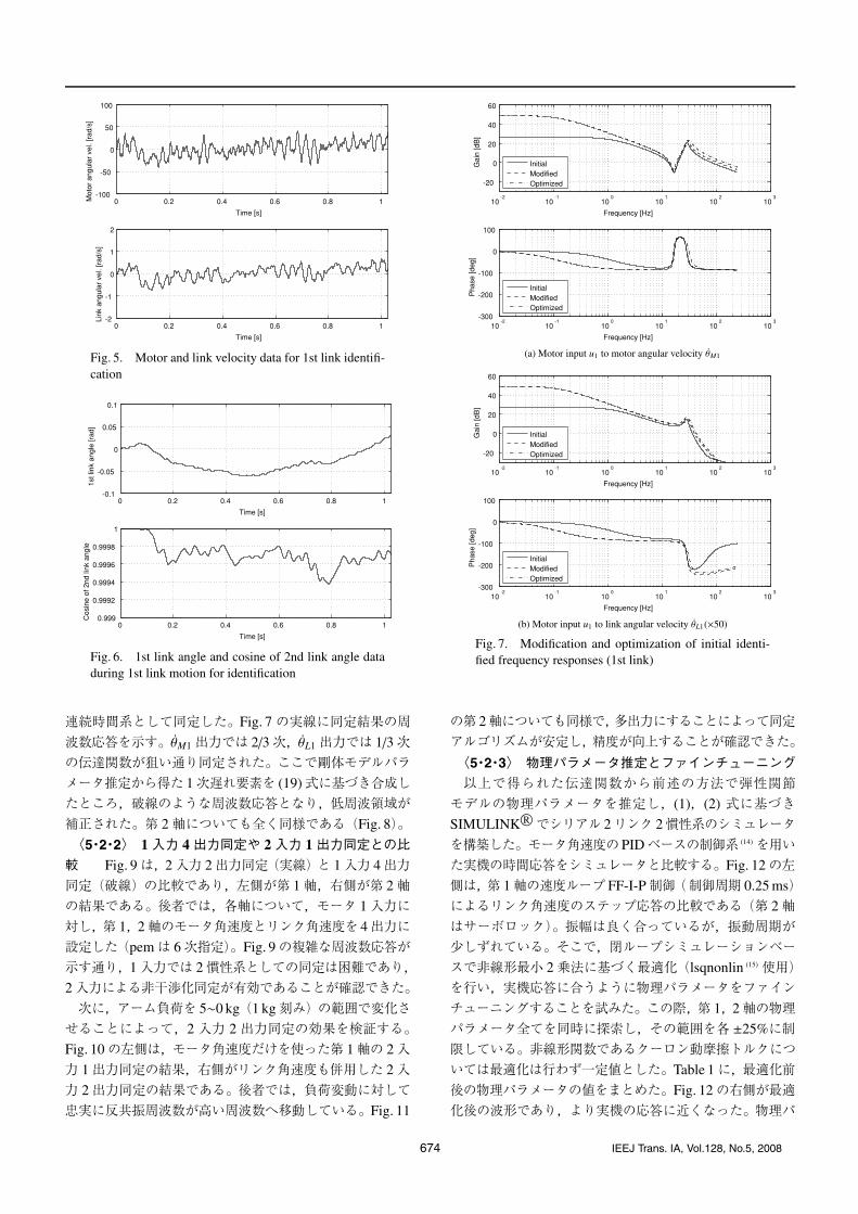
Fig. 5. Motor and link velocity data for 1st link identifi-cation
Fig. 6. 1st link angle and cosine of 2nd link angle dataduring 1st link motion for identification
連続時間系として同定した。Fig. 7の実線に同定結果の周
波数応答を示す。θM1出力では 2/3次,θL1出力では 1/3次の伝達関数が狙い通り同定された。ここで剛体モデルパラメータ推定から得た 1次遅れ要素を (19)式に基づき合成したところ,破線のような周波数応答となり,低周波領域が
補正された。第 2軸についても全く同様である(Fig. 8)。
〈5・2・2〉 1入力 4出力同定や 2入力 1出力同定との比較 Fig. 9は,2入力 2出力同定(実線)と 1入力 4出力同定(破線)の比較であり,左側が第 1軸,右側が第 2軸の結果である。後者では,各軸について,モータ 1入力に
対し,第 1,2軸のモータ角速度とリンク角速度を 4出力に設定した(pemは 6次指定)。Fig. 9の複雑な周波数応答が示す通り,1入力では 2慣性系としての同定は困難であり,2入力による非干渉化同定が有効であることが確認できた。
次に,アーム負荷を 5∼0 kg(1 kg刻み)の範囲で変化させることによって,2 入力 2 出力同定の効果を検証する。Fig. 10の左側は,モータ角速度だけを使った第 1軸の 2入力 1出力同定の結果,右側がリンク角速度も併用した 2入
力 2出力同定の結果である。後者では,負荷変動に対して忠実に反共振周波数が高い周波数へ移動している。Fig. 11
(a) Motor input u1 to motor angular velocity θM1
(b) Motor input u1 to link angular velocity θL1(×50)
Fig. 7. Modification and optimization of initial identi-fied frequency responses (1st link)
の第 2軸についても同様で,多出力にすることによって同定アルゴリズムが安定し,精度が向上することが確認できた。
〈5・2・3〉 物理パラメータ推定とファインチューニング
以上で得られた伝達関数から前述の方法で弾性関節モデルの物理パラメータを推定し,(1),(2) 式に基づきSIMULINK R©でシリアル 2リンク 2慣性系のシミュレータ
を構築した。モータ角速度のPIDベースの制御系 (14)を用いた実機の時間応答をシミュレータと比較する。Fig. 12の左側は,第 1軸の速度ループ FF-I-P制御(制御周期 0.25 ms)によるリンク角速度のステップ応答の比較である(第 2軸
はサーボロック)。振幅は良く合っているが,振動周期が少しずれている。そこで,閉ループシミュレーションベースで非線形最小 2乗法に基づく最適化(lsqnonlin (15) 使用)を行い,実機応答に合うように物理パラメータをファイン
チューニングすることを試みた。この際,第 1,2軸の物理パラメータ全てを同時に探索し,その範囲を各 ±25%に制限している。非線形関数であるクーロン動摩擦トルクについては最適化は行わず一定値とした。Table 1に,最適化前
後の物理パラメータの値をまとめた。Fig. 12の右側が最適化後の波形であり,より実機の応答に近くなった。物理パ
674 IEEJ Trans. IA, Vol.128, No.5, 2008

2リンク 2慣性系の非干渉化同定
(a) Motor input u2 to motor angular velocity θM2
(b) Motor input u2 to link angular velocity θL2(×50)
Fig. 8. Modification and optimization of initial identi-fied frequency responses (2nd link)
Fig. 9. Effective examples for multi-input identification(Motor input to motor angular velocity). Left: 1st link.Right: 2nd link
ラメータ最適化後の周波数応答を Figs. 7,8の 1点鎖線に示した。共振周波数がわずかにずれたことがわかる。物理パラメータ最適化後の速度ステップ応答比較を Fig. 13(第
1軸),Fig. 14(第 2軸)に示す。Fig. 13での第 2軸,Fig. 14
での第 1軸はサーボロック状態である。各軸のモータ角速
Fig. 10. Effective examples for multi-output identifica-tion (1st link) under changing payload. Left: 1 output.Right: 2 outputs
Fig. 11. Effective examples for multi-output identifica-tion (2nd link) under changing payload. Left: 1 output.Right: 2 outputs
Fig. 12. Optimization-based fine tuning of estimatedphysical parameters using 1st link angular velocity stepresponses. Left: Before optimization. Right: After opti-mization
度・リンク角速度・モータ駆動入力について,実機の波形
に合ったシミュレーション結果が得られており,物理パラメータ推定が良好に行われていることを示している。
6. おわりに
多入出力状態空間モデル同定法を応用したシリアル 2リ
ンク 2慣性系の非干渉化同定と物理パラメータ推定の方法を提案し,2リンクアーム実機に適用して得られたモデル
電学論 D,128 巻 5 号,2008 年 675

Table 1. Estimated physical parameters before and afternonlinear optimization
Before opt. After opt.
α [kgm2] 2.39 2.27
β [kgm2] 0.865 0.742
γ [kgm2] 0.731 0.740
mM1 [kgm2] 9.75 × 10⁻⁴ 6.30 × 10⁻⁴
mM2 [kgm2] 4.34 × 10⁻⁴ 2.80 × 10⁻⁴
kG1 [Nm/rad] 53800 46300
kG2 [Nm/rad] 28900 25300
dL1 [Nms/rad] 2.84 3.06
dL2 [Nms/rad] 2.44 2.62
dM1 [Nms/rad] 1.10 × 10⁻³ 7.35 × 10⁻⁴
dM2 [Nms/rad] 9.75 × 10⁻⁴ 6.30 × 10⁻⁴
dG1 [Nms/rad] 49.0 52.7
dG2 [Nms/rad] 20.3 21.9
Fixed parameters
fM1 [Nm] 0.196
fM2 [Nm] 0.140
System parameters
e1 [Nm/V] 0.56
e2 [Nm/V] 0.56
nG1 1/50
nG2 1/50
Fig. 13. Examples for model accuracy validation usingvelocity step responses (1st link). Left: Real arm. Right:Simulation
Fig. 14. Examples for model accuracy validation usingvelocity step responses (2nd link). Left: Real arm. Right:Simulation
の有効性を確認した。実際のスカラロボットの手先の回転軸(第 4軸)に長尺の負荷が取り付けられた場合には,シ
リアル 3リンク 2慣性系として扱う必要が生じる。本文中で述べた可同定条件を満たすことを確認する必要があるが,本稿で提案した方法を拡張して適用可能であると考えている。今後の応用先として,物理パラメータの変動範囲を考
慮したタイトなロバスト制御系や,ゲインスケジューリング制御系の設計への適用を検討していく。(平成19年10月12日受付,平成20年1月19日再受付)
文 献
( 1) Y. Nishida, T. Nishimura, K. Honke, H. Nakagami, Y. Imaizumi, andN. Kimura: “Robust Control Method for Industrial Robot Manipulatorswith Flexible Joints—Application of State Observer and Two-Degree-of-Freedom Controller—”, J. RSJ, Vol.12, No.3, pp.466–471 (1994-4) (inJapanese)西田吉晴・西村利彦・本家浩一・中上敬之・今泉吉規・木邑信夫:「柔軟関節を持つマニピュレータのロバスト制御—オブザーバと 2自由度コントローラの適用—」, 日本ロボット学会誌, Vol.12, No.3,pp.466–471 (1994-4)
( 2) Y. Kosaka and A. Shimada: “Robot Manipulator Control Considering Mo-tors and Reduction Gears”, T. SICE, Vol.41, No.5, pp.466–472 (2005-5) (inJapanese)小坂裕紀・島田 明:「モータと減速機を考慮したロボットマニピュレータ制御」,計測自動制御学会論文集, Vol.41, No.5, pp.466–472 (2005-5)
( 3) M.C. Readman: “Flexible Joint Robots”, CRC Press (1994)( 4)(株)ハーモニック・ドライブ・システムズ:「減速機カタログ」( 5) I. Awaya, Y. Kato, Y. Ohta, I. Miyake, and M. Ito: “Parameter Identifica-
tion Method for Two Inertia Resonant Systems by Use of Both Observerand FFT”, T. JSME, Ser.C, Vol.60, No.572, pp.1175–1181 (1994-4) (inJapanese)粟屋伊智郎・加藤義樹・太田裕二・三宅岩夫・伊藤正美:「オブザーバと FFT を併用した 2 慣性共振系のパラメータ同定法」,日本機械学会論文集(C 編), Vol.60, No.572, pp.1175–1181 (1994-4)
( 6) S. Wakui and T. Mita: “Degrade of Identification Accuracy of Inertial Termscaused by Coupling Vibration and its Modification”, J. RSJ, Vol.7, No.3,pp.195–198 (1989-6) (in Japanese)涌井伸二・美多 勉:「連成振動による慣性項同定精度の劣化とその改善」,日本ロボット学会誌, Vol.7, No.3, pp.195–198 (1989-6)
( 7) 計測自動制御学会編:「ロボット制御の実際」, pp.62–80, コロナ社(1997)
( 8) N. Takesue, J. Furusho, and K. Iwakoshi: “A Consideration on Inertia-Ratioand Vibration Control of Two-Inertia System—Effectiveness of VibrationSuppression of Driving Ripple—”, IEEJ Trans. IA, Vol.123, No.2, pp.149–155 (2003-2) (in Japanese)武据直行・古荘純次・岩越邦男:「二慣性系の慣性比と振動制御に関する一考察—駆動伝達リプルの振動抑制効果—」,電学論 D, 123, 2,pp.149–155 (2003-2)
( 9) 美多 勉・大須賀公一:「ロボット制御工学入門」, pp.238–239,コロナ社 (1989)
(10) 松日楽信人・大明準治:「わかりやすいロボットシステム入門—メカニズムから制御まで—」, pp.84–85,オーム社 (1999)
(11) 足立修一:「MATLABによる制御のための上級システム同定」, pp.300–304,東京電機大学出版局 (2004)
(12) J. Oaki and S. Adachi: “Simultaneous Identification Method for FrequencyResponse and Physical Parameters of a Robot Arm”, T. SICE, Vol.26, No.12,pp.1461–1463 (1990-12) (in Japanese)大明準治・足立修一:「ロボットアームの周波数応答と物理パラメータの同時同定法」,計測自動制御学会論文集, Vol.26, No.12, pp.1461–1463(1990-12)
(13) L. Ljung: “System Identification Toolbox For Use with MATLAB (Version7.0)”, The MathWorks (2007)
(14) J. Oaki and S. Adachi: “A Digital Servo Tuning System for IndustrialRobots”, T. RSJ, Vol.9, No.1, pp.55–64 (1991-2) (in Japanese)大明準治・足立修一:「産業用ロボットのディジタルサーボチューニングシステム」,日本ロボット学会誌, Vol.9, No.1, pp.55–64 (1991-2)
(15) The MathWorks: “Optimization Toolbox For Use with MATLAB (Version3.1.1)”, The MathWorks (2007)
676 IEEJ Trans. IA, Vol.128, No.5, 2008
2リンク 2慣性系の非干渉化同定
付 録
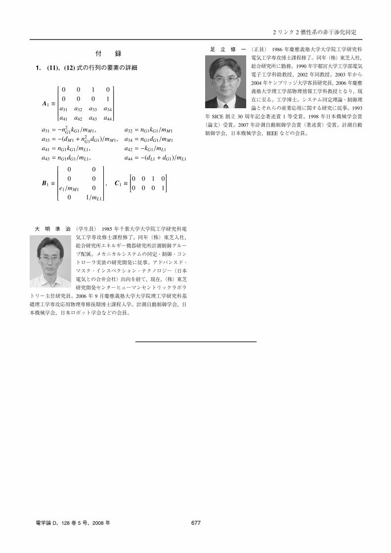
1. (11),(12)式の行列の要素の詳細
A1 ≡
⎡⎢⎢⎢⎢⎢⎢⎢⎢⎢⎢⎢⎢⎢⎢⎢⎢⎣
0 0 1 0
0 0 0 1
a31 a32 a33 a34
a41 a42 a43 a44
⎤⎥⎥⎥⎥⎥⎥⎥⎥⎥⎥⎥⎥⎥⎥⎥⎥⎦
a31 = −n2G1kG1/mM1, a32 = nG1kG1/mM1
a33 = −(dM1 + n2G1dG1)/mM1, a34 = nG1dG1/mM1
a41 = nG1kG1/mL1, a42 = −kG1/mL1
a43 = nG1dG1/mL1, a44 = −(dL1 + dG1)/mL1
B1 ≡
⎡⎢⎢⎢⎢⎢⎢⎢⎢⎢⎢⎢⎢⎢⎢⎢⎢⎣
0 0
0 0
e1/mM1 0
0 1/mL1
⎤⎥⎥⎥⎥⎥⎥⎥⎥⎥⎥⎥⎥⎥⎥⎥⎥⎦
, C1 ≡⎡⎢⎢⎢⎢⎢⎣0 0 1 0
0 0 0 1
⎤⎥⎥⎥⎥⎥⎦
大 明 準 治 (学生員) 1985 年千葉大学大学院工学研究科電
気工学専攻修士課程修了。同年(株)東芝入社,
総合研究所エネルギー機器研究所計測制御グルー
プ配属。メカニカルシステムの同定・制御・コン
トローラ実装の研究開発に従事。アドバンスド・
マスク・インスペクション・テクノロジー(日本
電気との合弁会社)出向を経て,現在,(株)東芝
研究開発センターヒューマンセントリックラボラ
トリー主任研究員。2006 年 9 月慶應義塾大学大学院理工学研究科基
礎理工学専攻応用物理専修後期博士課程入学。計測自動制御学会,日
本機械学会,日本ロボット学会などの会員。
足 立 修 一 (正員) 1986 年慶應義塾大学大学院工学研究科
電気工学専攻博士課程修了。同年(株)東芝入社,
総合研究所に勤務。1990年宇都宮大学工学部電気
電子工学科助教授,2002 年同教授。2003 年から
2004年ケンブリッジ大学客員研究員,2006年慶應
義塾大学理工学部物理情報工学科教授となり,現
在に至る。工学博士。システム同定理論・制御理
論とそれらの産業応用に関する研究に従事。1993
年 SICE 創立 30 周年記念著述賞 1 等受賞。1998 年日本機械学会賞
(論文)受賞。2007 年計測自動制御学会賞(著述賞)受賞。計測自動
制御学会,日本機械学会,IEEE などの会員。
電学論 D,128 巻 5 号,2008 年 677