decontamination chamber for the maintenance of dupic
TRANSCRIPT

KR0100814
KAERI/TR-1658/2000
Decontamination Chamber for the Maintenance of DUPICNuclear Fuel Fabrication and Process Equipment

- 2000 <SJ£ "DUPIC *A<3.5-
(DUPIC) «!££. ^ ] S - ^ ^
2000. 10.

A}-g--f *q<35.(FWR spent fuel)
M6
^ # £ S DUPIC^^S
°.E.5, 7}
!c: DUPIC
57^ SLfS
7]
- 1 -

Abstract
DUPIC nuclear fuel is to reuse PWR spent fuel as a raw material
and is fabricated through a variety of processes. DUPIC nuclear fuel
fabrication processes are conducted in the M6 hot-cell of the IMEF
(Irradiation Material Examination Facility) at KAERI (Korea Atomic
energy Research Institute) because of the nature of the high
radioactivity of spent fuel. All the process and treatment equipment
were designed and constructed to be operated remotely because direct
human access to the in-cell is not possible.
DUPIC nuclear fuel fabrication equipment and handling devices are
apt to be contaminated with high radioactive particles because the high
radioactive materials are treated in the fabrication processes. In the
case of which such equipment and devices are malfunctioned in use,
they needs to be repaired and maintained in the hot-cell or outside of
the hot-cell. The human operator can not deal with the contaminated
equipment and devices by direct contact. Therefore, the
decontamination needs to be done on such malfunctioned equipment
before they are put into service for maintenance. The decontamination
process needs to be conducted in a isolated and closed room to prevent
contamination from spreading over the hot-cell.
This report presents the decontamination chamber of being capable
of decontaminating and maintaining DUPIC nuclear fuel fabrication
equipment contaminated in use. The developed decontamination
chamber has mainly five sub-modules - a horizontal module for
opening and closing a ceil of the chamber, a vertical module for
opening and closing a side of the chamber, a subsidiary door module

for enforcing the vertical opening/closing module, a rotary module for
rotating contaminated equipment, and a grasping module for holding a
decontamination device. Such sub-modules were integrated and
installed in the M6 hot-cell of the IMEF at the KAERI. The
mechanical design considerations of each modules and the arrangement
with hot-cell facility, remote operation and manipulation of the
decontamination chamber are also described.

1^ 3
3
2. 1 ^ 3 ^7J1JI^A>%> 3
3. tfAfl'gXI ^ ^ l l ^ } ^ 20
3 ^ ^ l ^ ^ l ] ^ ^ 24
1. 7flA 24
2. ^7fl3j |£.!- 28
3. ^2}7})5)]S# 32
4. ^L2 :£^a l - 37
5. SI^S-l- 40
6. 4^ ] S-# 43
7. ^t*iW# ^ ^^^-§" 46
4 ^ £ <& 53
J L ^ 54

s.
3. 1.
S 2.a 3.S. 4.
S. 5.
313 6
40
45
50
- v -

l.
2.
3.
4.
5.
6.
7.
8.
9.
10.
11.
12.
13.
14.
15.
16.
17.
18.
19.
20.
21.
22.
25
• 26
M6-B «HH <i*l€
^ 2 7
29
303334
34
35
37
38
39
41
41
42
43
44
45
47
48
48
49
- VJ -

spent fuel)* *fl 4-8-«H ^ S £ ] ^ r ^ s } DUPIC I "SSfe
3.3, 4^ -€4 . DUPIC^H^ ^ - g - ^ S S . ^ jL^Apg ^§-41 2:A>*fl
- ^l-JL, SJ^S^ ^2:^-^1- 7]^Ai s | s DUPIC
DUPIC^^S. ^•^^S^-^oflA^ «a^^r 3.7]3,
^: 71 *
— 1 ~

^. DUPIC
-r
7]
7]
- 2 -

m 3.^ 2-1-
7171^ 717]
7>-g-7)
9XSLS.
2.
- 3 -

$.£}.. S
A}
(1)
HCU, Np, Pu, Am -^, a,
n), V)
(2)
- 4 -

(3)
3L
l a b e l
(4)
41 - 46, ^^l7> 30 - 41, #6] 15 - 20 cm
oj ^1^1-
i S S « CCTVi 1:
- 5 -

(5)
^ 31^-ofl
(6)
(7)
- 6 -

7]
(7» Lifting bail
baii-i-
bail
^ ^ ^ - JSL
150%^] §>^ # £ 1 - 7 l ^ A S . 2W11
bail
l i f t
- 7 -

bailor ^ ^ " H r 3 H M ^ o H ^ S . single point Iift7>
* H # ^f-^ SLQo) l-M^MJSLS multiple^ ^
12|- bailor ^i^n <£^.Z}JL bailor ^ A
(M-) Rest point
-^ ^-Hlfe rest point7>
£-€• 7]7 l^ built-in alignment* ^l-g-^fe^l rf-g-
^ 2
3 - 5 mm
galling olM- binding
- 8 -

CCTV
^ « " ^ Sl^r 31^1-8- -a^«>fe- ^°] wf -z) §f4. | 1 A ] pilot nosed
end ^^1 ot# 7 >^§H ^>-g-^ ^ H 5a^m ^Hr$ J L ^ # ^
^ l ^ f f e ^ ^ w}^2]^^] ^ 4 . tH^-^-S] # E ^ ^ . i m p a c t
nut runner* ol-g-^fe-^ ° H
^ 6 mm
deburring ^ *
ACME threaded fastener* *r-8-*}^ 7A°] *
^ Rockwell C45
- 9 -

7}
fe S.#^r toggled M- clamp
Snap rings, roll pins, spring clips ^-& ^
(8)
^ ^ pit
3.7)1 ^>^ *rW^ ^ 7 ] 7 1 ^
A]
0.35 ± 25%
(1)
American Society for Testing and Materials(ASTM)°m- American
Society of Engineering Pressure Vessel and Boiler Code(ASME Code)
- 10 -

7] 7 1 ^ Z - Jf^ofl
(2)
(7]-)
, Elastomer
. 3.71^ #5.,
108 ra
io7io5 - 1000
(4) M)
- 11 -

~ 61 ~
I© -R
O; itieisisar
lb
«P
0]^ f r [ o %g-g
•-b
I©
^ -tain
\xx-k lo|B
s ^ i z [O-§-4Y
I©
008 Uin IKfe •§•:&&> lb-{?Iilb IKfe: I©

deburring-i- *
galling^ ^
Nitronic 60
PH) 1-S^ Nitronic uiS
Cross-thread U-^ll- ^
# 2 : ^ : # ^ l o ] o -T-f t S f s o ) ^ ^ J L ^ A] galling*]
7] 31
(1)
^^^^m^l 1), 2)
Lift point7>
- 13

ZL
7]
(2)
«H background radiation^
°l£itt 4^^: 7 ^
S., ^ ^
(7]-) Mechanical drive
•I:
torque-limiting shear pin#
o]] <>]$.•%
(M-) Gear trains
- 14 -

Gear trainer
^17>
Large-tooth gearfe
Couplings
SI 4 .
37))
o) ^ ^ - ^
-g- jaw
pinned
^ ^ <>l-8-t1-7l
5LB\s>\
. Male/female
- 15 -

spline Si-
^ ^-n-7]- ^ ^ . ^ M , SE r Open spur^)- bevel 7 H 5 .
SI4.
50ppm
71
(pl-) Power screws
Power screws H€°ll^
i A £ B>^T^ ^ # ^ ^ 1 ^ 1 4 . ACME f ball ^Bfls] screw7>
ACME screws ASA standards B1.3°ll 4 ^ ^ ^ ] ^ 4 . Ball screw
- 16 -

5} ^
n *1] H 5U4.
viSfe screws
screw, MS, £*\}g.
(3)
) ^ A>-g-5||o>
screw, slide-way ^WMfe
astener treads, jack
Molybdenum disulfide^^- S:^:4
phosphates, flame spray, silicates
«K Seals
(1) Mechanical static seals
• Elastomeric seal rings :
in^r 108 rads
elastomer^ thermoplastic
Adiprene
Cm urethane rubber^ 109
seal exposed^ ^ ^ -
captive o-ring groove7|- 13
Metallic seal ring :
"sucker stickck"-i- access slot
4.
- 17 -

Packing : ^^ ^ A 3 . asbestos-graphite(John Crane)^- graphite
(Grafoil)7l- S ^ : 7}±§-s}v\
(2) Rotary shaft seal
, /stellite S ^ -S-^^fl^/^^ #«] ^ ^
1A^ 4€- ^r£ ^-# bellow7|- ^fe 1
-g-^]^# j&^Sfl § 4 . Labyrinth seal^:
(3) Linear shaft seal
•§•# bellow seal^] 7HV ^ ^ ^ 1 Af-g-^ 4" $14. ii?)]*|-^r bellow^)
Elastomeric wiper7>
£3^0)
K Covers and enclosures
(1) Unit shielding
- 18 -

(2) Isolation enclosures
«r. Connector design
(1) Hanford-Purex(HP) connector
H P ^ 50 - 100 mm ^ 3.7} ^^ofl ^o] Aj-g-^cf. o)c) m
^r self-aligning<^H 1 - S * fb 7fl V Aj-^-^4. J E ^ 2 j ^ ^ ^ l o ) l ^
^ - ^ ^r SI 4 . ^ ^ - 7fl^-A]o]]^ Teflon, glass-reinforced Teflon
plastic/elastomeric
Gamah, Grayloc^l Grafoil^r *f-*\*\7]
(2) TRU connector
6 - 12 mm
TRU connector^
male ferrule^-
10
0RNI>H 7
female ferrule^: ^ 20£,
S14 ^ # ^ > ^ S ^ ^ r ^ 4 ^ 0 ^ 4 -
700kPa(100 psig) 4*1 £ ^ H sealer
19 -
(3) Flanges
captured featured «>aL guide
guide pin
guide
•Sealer
(4) Tube fitting
^^r l t ^ € fitting^:
^r Si^-^ double ferrule^ ^^-o] ^cf. Cross-threading-g
.M- ferrule^ 51^1^717> %%
3.
7K
, ALARA(As Low
- 20 -

As Reasonably Achievable)
iL<3€ DUPIC
M6
M6
•M6-B
4) 1 ^ 371)
71 ^
^r -fhli Si H] (utility)^
^ - ^ ^ ^ (operating areaWM
- 21 -

fe ^ 7 }
2 1-
(1)
(2) ^ MEF M6-B
7]
(4)
(5)
- 22 -

(6)
(7)
(8)
(9)
(10)
(11)
(12)
- 23 -

7fl_£L
M6-B
roof door
H M6-A
#(isolation room)S °1
, M6-A
fe- M6-B 7) 7l
fe M6-B ^-(shielding window)
y)
^ ^ ; c]Aj-
- 24 -

M6-B
fe M6
^: M6-B
4^r cell
^ M6-B
1.
- 25 -

- 26

A-1 A-2 B-1
A :
B :
C : , D
, A~2 : ^
S., B-2 : # c ^, E : 4 1 £ t
3. MEF M6-B
- 27 -

2. *
f^ telescopic^ Bfl 5. J i^^sl :3}- ol-g- j 2.1-3.
7} AW »}£. $ H ^ l ^ ^ C ^ 3 ^"2:). 3L% 44
4 5L%.2i
7l
^-f)4 a.511^1^4 ^>^# wfl
^ H ^ o j - o ] ^ + 012=.
(workspace)^>1
6.3. hook#
hook* ^JL ^ l ^ ^ S . ^ ^ ^ R r ^ ^ l ^ H -g-g-
tfl
- 28 -

I—
* LJ
••_r\iSECTICW • * " - • * •
fate
CO* B U 3 T CHAMBER
4.
- 29 -

- 30 -

3. 1.
*|*r(LxWxH)(mm)
Stroke (mm)
Pulling force (N)
1300x1484x30
SUS 304
telescopic^
^ ^
1214x1450x30
SUS 304
1000
0.7
°]-8-^: ^ ^ ^ ^
1- ^1-8- : %}<£*] ^ 4
- 31 -

3.
tfj
64 n ^ 7^
] rf. ZL^ 8
(straightness)^:
4.
- 32 -

-—vyya
"D" <SCAt8 :
I !«».!
co. BUST C1UHBoiuisa
6.
- 33 -

7.
ii
(d
1 •J
ji
r—'
.!
8.
- 34 -

9.
- 35 -

S. 2. ^r^l 71)^2.1-
^ 3 1 ^ (LxWxT) (mm)
Stroke (mm)
1432x220x3
9
1975
^ ^
SUS 304
^ J l ^ - i : f-tt vision feedback^]
- 36 -

4.
i . , i . , r » » I » . I
MB OH) «ai4»)
\aaai
1
430
r /
\
. ^
\\
60
f
A l XX i £ 1LS. ±±
10.
- 37 -

11.
- 38 -

12.
- 39 -

5.
134 n^ 14^
^ CW/CCW y o H ^
Si o.
i - <>}•%•*}
3.
^ ^ « f ^ (kg)
^ ^ ^ ^ r ( ^ : mm)
^ t f l ^ S (rpm)
1000
1000
0 a -i
CW/CCW
30
- 40 -

13.
3 35 •
SCCTlON A-A*
m
1 * ~ ^ i ~ * ^ 1 * 1 * * l ****
v CCCOn. Cmuac*
14.
- 41 -

15.
- 42 -

6. 4 *
- - 4*1
* l * l t f i l -
16. 4*
- 43 -

17.
- 44 -

18.
5. 4.
Motion axis
/8"&} stroke (mm)
2)-T- stroke (mm)
£J^4(degree)
Head grasping pressure
350
300
180
56 kgf/cmz
- 45 -

7.
y\.
4s}
5.^) afe
195} n^J 20^: MEF
M6 ^ A 2-##
. A S#^
A]
22
- 46 -

[ DeCOMTAMINATON CHAMBER 1
SHUTTSA ro«B TUflNBHGTAeiS
[ ON '
oOFF
OcnH
oo
CLOSE
o
o£-BTO(*
oeuNKOComON Off •
O O
oCLOSE
o
r ' Of* 1
oOff
occwooCW
o
5T£T"LJ . " "
DF.J..
"" kM
ecu
U
V a
P
* * •
I
c*
C
MrtJ hMi
19.
- 47 -

20.
21. 4 £t#
- 48 -

22.
- 49 -

3. 5. f
#&
cw
ccw
0
0
0
0
0 0
0
0
0
o
- 50 -

IMEF M6
(1)
(7]-)
4^,
^.S. M6-A
roof doorl- f-
- 51 -

(71-) -
(2)
5L
- 52

DUPIC
S i r ^ 57]]S]
7l
- 53 -

1. Burgess, T .W. et al, "Design Guidelines for Remotely Maintained
Equipment," ORNL/TM-10864, (1988).
2. ^tflfl- $], " ^ ^7]l7l^" KAERI/AR-468/97(1997).
3. <&*$& $\ "^ - ^AnQ^^n^^Q l ^71 # 7fl -" KAERI/RR-1744/96(1997).
4. ^ 7 ] l 5], "^ • ^^S.^711 « n ^ a ^
KAERI/TR-1328/99(1999).
5. ^V;S-^1 s] "^ • ^^s.^!^l«ii
KAERI/RR-2009/99(2000).
- 54 -

A-i-i.
A-2-1.
A-2-2.
A-3-1.
A-3-2.
A-4-1.
A-4-2.
A-5-1.
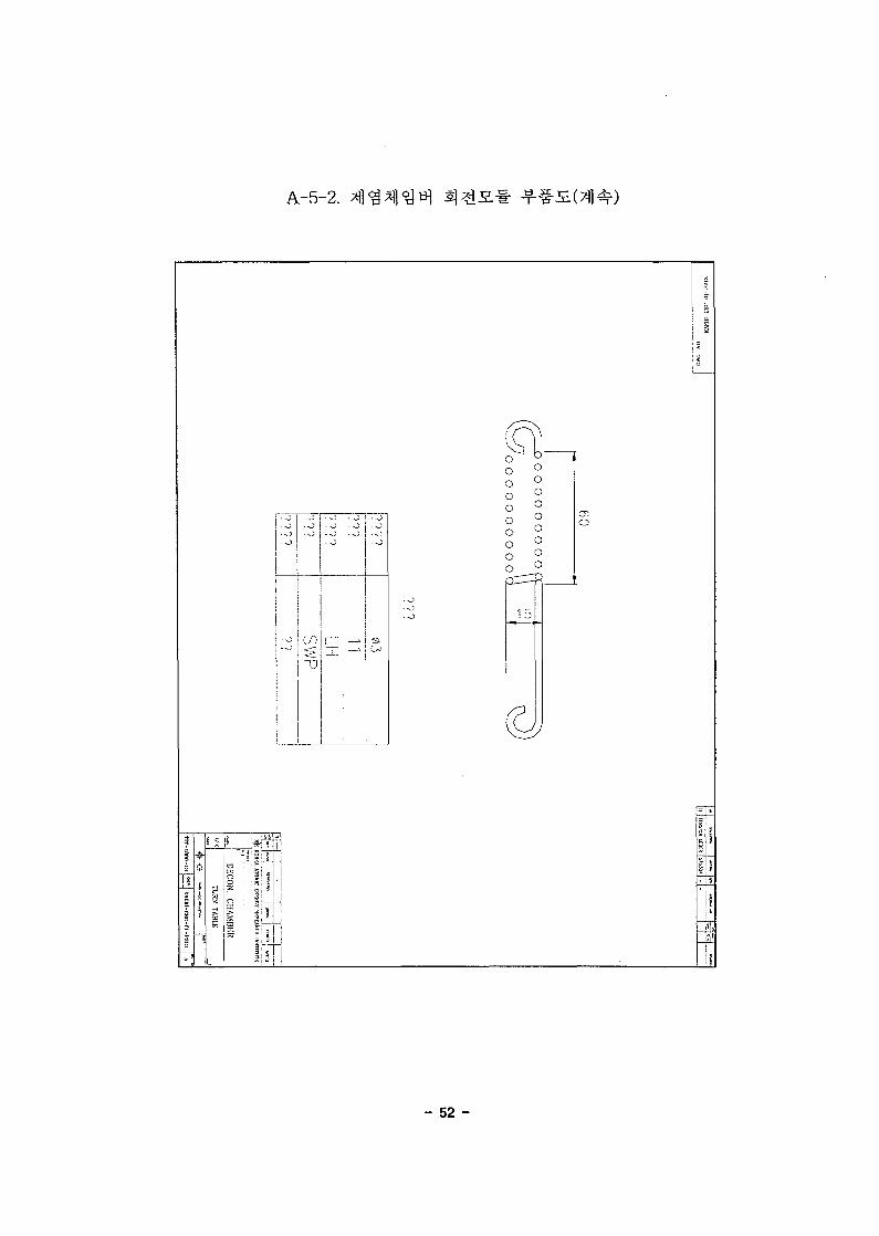
A-5-2.
A-6-1.
A-6-2.
A-7-1.
A-7-2.
2
3
4
9
10
29
30
38
39
55
56
71
72
- 1 -

uwv lo :»n i
r i" I '
* " ' | V
SECTION "I1"-"B'.SECTION *A"-"A"
SECTION T (SCALE : -I/I)
KORU ATOMIC tSKHflY Ht^UHCII INSTHIITK
DECON. CHAMIiKR
CIIAMREK
J KAERI-CDC'OI-ADOI

l-i
I r r
I I
\
;
1*52 i
i
13
i £ 1 6 :
S i
iaiif ii
Hiii
- 3 -

A-2-2.
~
1
i
j3
i
ri
j
j
»
rr[
•
•
:
:
i
1
J
j
II
I,!f
Si !
- 4 -

A-2-2.
¥-1
< i
- 5 -

A-2-2.
5 3
5P
" s i ;

A-2-2.
51B
- 7 -

m?ELf
Sf
ujni
CO
|- 1 i 1
^ I f-f&KOKEA ATOMIC KiKHr.Y HHIEASrll
I KAERI-CBC-01-P205
Ico

I ! I
In
>
5 S ill! !
$ 1^
- 9 -

nvi.t-nv-3m-w.1vn
UjnJ
iCO
<
_ LIo
3X
fiXKHrrf KESEAHCH ISSnTUTK
DKCON. CHAMBER
I KAERI-CIIC-01-CI01

A-3-2.
' i l
\fi
O fi
- 11 -

A-3-2.
J
- 12 -

VOW-10 .111.1- IIIHVM bffl
ultu
I
CO
CO
<
16.7 61.7
_"'!.. .
H KOREA ATOMIC ENERGY RESEARCH IlJST
JiECON. CHAMBER
C1IAMIIKH
J KAERI-CBC-01-1'104

A-3-2.
- 14 -

.r.ti
uifl
IT
oo
__,. .1
zfflzz
DECON. CHAMBER
Rl-Clir 01 1'ios :

A-3-2.
- 16 -

(Kll/1 1(1 .111.1 IIWVSC
P|ni
IN
wrn s
fl_ JiJ
ooi
<
riL 200 J
1=11 • I ~r~I S I
8"
1! *•*••* " W » O S S O"** Cram IPP'O
"< KORF V ATOyiC KNEHCY KESEAHCIi INSTITUTE
DECON. CHAMBER
CHAMBER
„ ] KAKHI-CHC-OI-i'l

A-3-2.
- 18 -

A-3-2.
I e s l i
-. L
•JAI
>
I if 11 I .
- 19 -

A-3-2.
- 20 -

OHM -10 OH.VIIOVM
c\5CO
TT
WSPROCKET SPEC
CHAIN : RS60
TEETH : 17
P.C.D : 0103.67
1 O I E 5
^. i,^.1 CHAMFEH : CO.O
i. iW.' roi.cKAfJcc ; ii n - i ?
-N-toNM ATOMIC KNKNC.Y KVXYAWM iNsnTim:
DKCON. CIIAMHER
1 KAF.W-CHC-01-raiO
CM
I

A-3-2.
50oo
(/I
i; I n u mIII I I
- 22 -

A-3-2. H 31
\t
• i fnjii?
- 23 -

A-3-2.
i < i # J
895
P.C.D 115.74
-a — Q x'p m 5 C
O
- 24 -

K
ltd-10 .in.1 IH:-IVH
SI^g 4EAg 7lg S!
I
105
T
C.Bore Dp8
105 20
i• t -
35
in
,.15
r "%j
f-.
IT
a.
3 KOREA ATOMIC ENERGY RESEARCH INSTITUTE
DKCON. CHAMHKK
TAKE-UP
W "J KAERi-rtia-ai-pAOi
inCM

\*iw EMO PlA'E ISUSJ
WIN
<£)CM
COi
< KOHKA ATOMIC f:\KKCY fttsKAHQI INSTITUTK
DECON. CHAMBKR

A-3-2.
56.5 56.5
I 5 II * !Sg.
- 27 -

A-3-2.
5
J»f=
s -i li |
p
s.
m
CO
o3jz
en
oX• ^
- 28 -
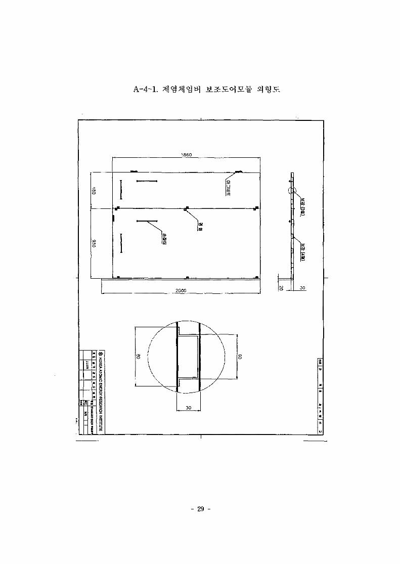
I860
HT.
HI
2000JO
/
1
1
!
o i"i
\\
1 "V.
1
30
\
\I1I
/
- 29 -

A-4-2.
549
26.5 J478
[|
26.5
<o
9
26.5
T T
1858
1929
9
26.5
28.5
10
1860
- 30 -

TEH.60
12
T
1
11
2.0t(SUS)
|
j
13C
11
1858
CO
I
KOREA ATOMIC ENERGY RESEARCH INSTITUTE
J. t M«m [ K C T . . ,H
- M1 I I

A-4-2.
28.5
1858
1929
9
26.5
10
1860
- 32 -

A-4-2. Hffi
- 33 -

A-4-2.
- 34 -

A-4-2.
__l_l .1.
23 21 18
g
165
- 35 -

A-4-2.
O
20
- 36 -

A-4-2.
(M
1 II II II II ]
4- 4-
VD-
mIfOSm
- 37 -

- 38 -

A-5-2.
! S
IS i\
I ; ;
i ; !
- 39 -

A-5-2.
l'-v s i ? i : ; j i i?• =!S I ;|LL.s _ IS I :au3 i i"- : . , . i '
! !-£>•
| S1 ) 2
1 | «
ill
Wt ,
ii
[
i
-
Xs
1!:-,
- 40 -

A-5-2.
!LUL_J*2
i j l
- 41 -

A-5-2.
i 1 - 1 '
1i
i
I
5
{t
s!
1
- 42 -

A-5-2.
fr; r ^ \J
-IZ^L
WCD
.*rn
5:
5:1
5
HULL1UT
- 43 -

ujni1
•gn
IJKCON. CIIAMHKK
TUKN TABLE

A-5-2.
inn
JEL
s w
- 45 -

A-5-2.
i
L 1
or
i 1 :t .
(SI 4 1
j
PCD
~ooo&CON>NJ
-o•o
=teO".
co
1
li
ss
n
i t
LLLii!
! I
- 46 -

M" " t P
4"
Mia
UtJU
EHVWw
•50
PCD
SP'iOCKLt WHEEL
OR
1!)
//60 "
PCDB9I .62•{ KOREA ATOHIC ENERGY RESEARCH INSTITUTE
DKCON. CHAMHKR

A-5-2.
3 :H(~li
4 1 i sISi s •
11
«2.2_
ILt
- e8 T
5
!
- 48 -

A-5-2.
CO
—
< :
M
o
c
. 0
- 0
CD
• j
• 0
X
s
- 49 -

A-5-2. Id
roCO
on
90
iro
IP!
- 50 -

Or
HVW
LO
DKCQN. CHAMBER
I
A-5-2.
• o-o
-o
• o
C/)
• o-o• o
s.
-o
- 52 -

A-5-2.
i i
! '-
UJJ -.
- 53 -

A-5-2.
3|
Tsi I!g 1 i i
I s i .C 5 '
> l I
- 54 -

i~_LLU= - — • 9 «-«^s -
wttez:£zte^sr
- 55 -

' I * » ! •
Pin)P-lK
+ •+-
480
500
10
I
CD
$ KOREA ATOMIC ENEFK3Y RESEARCH INSTITUTE
"" I I

I " I " " I '
Midif
Ptn)
ft
+ + f • •*- • -<
?0 I 60 60 60 60 1 60 6C 6fl 28.b
si
S-W5TAP20
Ti
10
o•JO
KOREA ATOMIC ENERGY RESEARCH INSTITUTE
I I

I B« [ a i [ a 11 + T ]
ft
K
0
0
^ | <
63 63
s~0—
inin
10.5
0. ^.
"1I—^. .->.
0 * -
142
.0
0
57.5
0
175
t I
s
•6-«7 HOIRS 16-M6 *AP
CO
<
111 1111
bJ 65.65
I I
13.6 65.5
410
£3.6 6b.6b 53 10
KOREA ATOMIC ENERGY RESEARCH INSTITUTE

A-6-2.
1C
- 59 -

A-6-2.
-0-
°
15
140
«24
PCO 65.5
135.4
-
15
165.4
- 60 -

" I " I 1 •
75 75
ulni
7 T
1 6 - M 6 TAP
CO
CD
! 197
mm
. . .
I
in
d
o
o
§
in
o
to
<o
KOflEA ATOMIC ENERGY RESEARCH INSTITUTE
I I

A-6-2.
250
=
10
1250
200
82.25 3!
00
1
en
t <
77
<>
>
4
.5 82.25
<
>•
•<
6
>
77
- 62 -

A-6-2.
3
os
4.5 35
6.8
in
14.4
*•
=
i
1
A
r-10
6 .8
s
Ul
en
4.5
- 63 -

" I " • ! • " ! •
Hi
wCD
i
<
11
PCD
1
1!
65.5
1
30
4-M6 TAP
/
KOREA ATOMIC ENEHQY RESEARCH INSTITUTE
A3 (*3fl.»Tl

A-6-2. 4
50
o
o
20 20 10
!
. _ _ .
12
• •• i !
\PC
D
47
6-M
6 TAP
- 65 -

A-6-2.
-0-
110
- 66 -

A-6-2.
ID
JO
77.5
5
0 0
o
i
S3
r h
L• — i — •
>
>
<
2
-
0
b
\soc1s
:5
- 67 -

A-6-2.
IL-
1
XtL
10
25
30
- 68 -

A-6-2.
0 8 0
PCD 65.5
O40
052o
- 69 -

eno
061
PCD 47
M25
56
\
s
IO•nyj
- 70 -

80 60 850
8
S
a
kxHI
2.
» J
n
n
K1
n
r»JLnj t
ra-U
1
i
K*?
m
*
s4*
i
I
- 71 -

A-7-2.
oo
3_ 530 55 265
850
f?
3
s m
7.
\ft
OJ
r
XI
R
>4
Ot
9
nt
ISHit*
A(2-
OS
a
<•
j
3
k
40
5
a»en
, /en 1o 1 j
1
o
- 72 -

A-7-2.
r;
- 73 -

A-7-2.
oo
50 430 50
530
- 74 -

A-7-2.
Or
c19
ISZl
380

A-7-2.
15
' \
13.5
12
427
478
13.512
- 76 -

A-7-2.
- 77 -

<? 2 * S U [gg |g g] a g | *•& [ * =
73:
T
•50
I
<
0/—
DECOMTAMINATION CHAMBER
—A,
SHUTTER POWEfl TURNIING TABLE
ON
0OFF
0OPEN
OSTALL
0CLOSE
0
0E-STOP
0GUN HOCDER
ON OFF
0 0OPEN
0CLOSE
0
450
ON
0OFF
0ccw0
STALL
Ocw0
in
CO
I b SuS

POWEB
SHUTTER POWER
TURNING TABLE POWER
3
t.T
i.
«"
-a-
OUN HOLDER OPEN
QUN HOLDER SOL V/V
OUN HOLDER CLOSE
OUN HOLDER SOL V/V
KOREA ATOMIC ENERGY RESEARCH INSTITUTE
» I * « * < £
I I

AI -1 ^ a. * 4
^ l ^ O L ^ J r
KAERl/TR-1658/2000
J-^- -7J ~?T
« * * * * 1 *
# ^ 1
4 ol .1
H] n] ol M
140 p.
INIS ^^\}3.B.
7J • 4rS.^7^1 (DUPIC) ^'SS. ^12: • ^ N
«7li(A>^M^S 71 MOT)
^ | 7 msa^-( 0 ) , &•§-( ) 3. 7]
2000. 10
255 Cm.
i ^ - (15-201^51)
~Ti n O 0 ^ 'I Tu
Cx3 TJ- "?J|1 Oj ^11 0^ - i j l i— <
jZ^^]-^" ^t's 7] •*•
(10^3: °) T-R-Sl)
DUPIC aj«3.
f^l^^r7> £.
I-Ji 4-e]t 4=glfe Al^Bflol
y ^ l u'T'-r Tfj- Q J ^ * * 1
* * * * *
• 4=- $1 - ^1 11 "t] iH °fl -5b ?}• 1-
* $X^ ' H . ^ I ^ ^•?J:^-5.^:j ^ll
nj * xi jy_4r ^ " ^ °1 ^"\3r ?-<^l
gj. 7 f l ^ ^ X l ^1 j li) 5] -£[2j
03 Xht)l R1
3l O tri rt- o3M " > 0 \-i
*M1 7fl^ ^
5-ll ^1 tJ-1

BIBLIOGRAPHIC INFORMATION SHEET
Performing Org.Report No.
Sponsoring Org.Report No.
Stamdard Report No. IMS SubjectCode
KAERI/TR-1658/2000
Title / SubtitleDecontamination Chamber for the Maintenance of DUPIC NuclearFuel Fabrication and Process Equipment
Project Managerand Department
K. H. Kim(Spent Fuel Technology Development Team)
Researcher andDepartment
J. J. ParkCSpent Fuel Technology Development Team),M. S. YangC). H. H. Lee("), J. M. ShinC)
PublicationPlace
Taejon Publisher KAERIPublication
DateOct. 2000
Page 140 p. I11.& Tab. Yes( 0 ), No ( ) Size 255 Cm.
Note
Classified Open( 0 ), RestrictedC ),Class Document
Report Type Research Report
Sponsoring Org. Contract No.
Abstract( 15-20 Lines)
This report presents the decontamination chamber of being capable of
decontaminating and maintaining DUPIC nuclear fuel fabrication equipment
contaminated in use. The decontamination chamber is a closed room in which
contaminated equipment can be isolated from a hot-cell, be decontaminated and be
repaired. This chamber can prevent contamination from spreading over the hot-cell,
and it can also be utilized as a part of the hot-cell after maintenance work.
The developed decontamination chamber has mainly five sub-modules - a
horizontal module for opening and closing a ceil of the chamber, a vertical module
for opening and closing a side of the chamber, a subsidiary door module for
enforcing the vertical opening/closing module, a rotary module for rotating
contaminated equipment, and a grasping module for holding a decontamination
device. Such sub-modules were integrated and installed in the M6 hot-cell of the
EVIEF at the KAERI. The mechanical design considerations of each modules and the
arrangement with hot-cell facility, remote operation and manipulation of the
decontamination chamber are also described.
Subject Keywords(About 10 words)
hot-cell, spent nuclear fuel and particle, contamination, highradioactive material, decontamination, decontaminationchamber