decommissioning methodology and cost evaluation 5-8. setting deck for seafastening ......
TRANSCRIPT

Decommissioning Methodology and Cost Evaluation
BPA No. E13PA00010 Call Order No. E14PB00056
Prepared for
U.S. Department of the Interior Bureau of Safety and Environmental Enforcement 45600 Woodland Road Sterling, Virginia 20166
Prepared by
Prepared by ICF Incorporated, LLC in collaboration with the Bureau of Safety and Environmental Enforcement 9300 Lee Highway Fairfax VA 22031

blankpage
Decommissioning Methodology and Cost Evaluation
ICF International iii
Contents Executive Summary ........................................................................................................................... ix
Background ............................................................................................................................................ ix Report Objectives Organization ............................................................................................................ ix Conclusions ............................................................................................................................................ xi
1. Introduction to the Decommissioning Methodology and Cost Evaluation Study ..........................1-1
2. Review of Previous Decommissioning Studies ............................................................................2-1 2.1. Review of the 2009 GOM Study ................................................................................................ 2-1 2.2. Review of the 2010 POCS Study ................................................................................................ 2-2
3. Structure and Asset Types .........................................................................................................3-1 3.1. Caissons ..................................................................................................................................... 3-1 3.2. Compliant Towers (CT) .............................................................................................................. 3-3 3.3. Fixed Platforms .......................................................................................................................... 3-4 3.4. Mobile Offshore Production Units (MOPU)............................................................................... 3-5 3.5. Floating Production, Storage, and Offloading (FPSO) Vessels ................................................... 3-5 3.6. Tension Leg Platforms (TLP) / Mini Tension Leg Platforms (MTLP) ........................................... 3-6 3.7. Semi-submersible Platforms (SEMI) .......................................................................................... 3-8 3.8. Spars .......................................................................................................................................... 3-9 3.9. Well Protectors (WP) ............................................................................................................... 3-10 3.10. Subsea Templates (SSTMP) ..................................................................................................... 3-12 3.11. Distribution of Structure Types ............................................................................................... 3-13
4. The Decommissioning Process ...................................................................................................4-1 4.1. Pre-job Activities ........................................................................................................................ 4-1 4.2. Well Plugging and Abandonment .............................................................................................. 4-3 4.3. Pipeline Decommissioning ......................................................................................................... 4-5 4.4. Platform Decommissioning........................................................................................................ 4-5 4.5. Disposal .................................................................................................................................... 4-10 4.6. Site Clearance and Verification................................................................................................ 4-11 4.7. Post-job Activities .................................................................................................................... 4-11
5. Facility Decommissioning Techniques and Methodology ............................................................5-1 5.1. Well Plugging and Abandonment .............................................................................................. 5-1 5.2. Pipeline Decommissioning ....................................................................................................... 5-10 5.3. Platform Decommissioning...................................................................................................... 5-15 5.4. Subsea Structure Decommissioning ........................................................................................ 5-21 5.5. Other Decommissioning Considerations ................................................................................. 5-21 5.6. Site Clearance/Verification ...................................................................................................... 5-24
6. Decommissioning Technologies .................................................................................................6-1 6.1. Well P&A .................................................................................................................................... 6-1 6.2. Well Intervention Vessels and Systems ..................................................................................... 6-7 6.3. Cutting and Severing ................................................................................................................ 6-10 6.4. Heavy Lift Technologies ........................................................................................................... 6-26
7. Selecting Decommissioning Technologies ..................................................................................7-1 7.1. Well Plugging and Abandonment .............................................................................................. 7-1

Decommissioning Methodology and Cost Evaluation
ICF International iv
7.2. Pipeline Decommissioning ......................................................................................................... 7-3 7.3. Umbilical Decommissioning....................................................................................................... 7-3 7.4. Platform Decommissioning........................................................................................................ 7-4 7.5. Subsea Structure Decommissioning .......................................................................................... 7-6 7.6. Decision Flowcharts ................................................................................................................... 7-7
8. Decommissioning Costs .............................................................................................................8-1 8.1. Introduction ............................................................................................................................... 8-1 8.2. Parameters Affecting Decommissioning Costs .......................................................................... 8-2 8.3. Estimated Costs ......................................................................................................................... 8-9 8.4. Comparisons of Actual and Estimated Decommissioning Costs ............................................. 8-40
9. Contingencies and Uncertainties Impacting Cost Estimating .......................................................9-1 9.1. Introduction ............................................................................................................................... 9-1 9.2. Contingencies ............................................................................................................................ 9-1 9.3. Uncertainties ............................................................................................................................. 9-5
10. Non-technical Impacts on Decommissioning Costs ................................................................... 10-1 10.1. Introduction ............................................................................................................................. 10-1 10.2. Inflation Impacts ...................................................................................................................... 10-1 10.3. Demand Impacts ...................................................................................................................... 10-3 10.4. Regional Impacts...................................................................................................................... 10-4 10.5. Market Condition Impacts ....................................................................................................... 10-7 10.6. Technology Impacts ................................................................................................................. 10-8 10.7. Regulatory Impacts .................................................................................................................. 10-9 10.8. Other Possible Impacts ............................................................................................................ 10-9
11. Safety and Environmental Accidents, Incidents and Events ...................................................... 11-1 11.1. Introduction ............................................................................................................................. 11-1 11.2. Data Sources ............................................................................................................................ 11-1 11.3. Safety Incidents and Events ..................................................................................................... 11-2 11.4. Environmental Incidents and Events ..................................................................................... 11-13 11.5. Risk Ranking ........................................................................................................................... 11-19
12. Analysis of Decommissioning and Facility Removal Regulations ............................................... 12-1 12.1. United States ........................................................................................................................... 12-1 12.2. Other IRF Member Countries .................................................................................................. 12-7 12.3. Other Jurisdictions ................................................................................................................... 12-9 12.4. Regulatory Matrix .................................................................................................................. 12-10 12.5. Regulatory Gaps ..................................................................................................................... 12-27 12.6. Suggested Modifications ....................................................................................................... 12-27

Decommissioning Methodology and Cost Evaluation
ICF International v
List of Tables
Table 3-1. Existing Structures in the GOM ............................................................................................... 3-13 Table 6-1. Heavy Lift Vessels .................................................................................................................... 6-27 Table 7-1. Well Plugging and Abandonment Techniques .......................................................................... 7-1 Table 7-2. Pipeline Abandonment Techniques .......................................................................................... 7-3 Table 7-3. Umbilical Decommissioning Techniques ................................................................................... 7-3 Table 7-4. Fixed Platform Decommissioning Techniques .......................................................................... 7-4 Table 7-5. Floating Platform Decommissioning Techniques ...................................................................... 7-5 Table 7-6. Subsea Structure Decommissioning Techniques ...................................................................... 7-6 Table 8-2. Dry Tree Well T&A in WD 50’ to 400’...................................................................................... 8-12 Table 8-3. Well T&A Basic Parameters with Casing Jacks ........................................................................ 8-14 Table 8-4. Dry Tree Well T&A in WD >/= 400’, 60 Wells per platform .................................................... 8-15 Table 8-5. Pipeline Decommissioning Cost .............................................................................................. 8-22 Table 8-6. Umbilical Removal Costs ......................................................................................................... 8-23 Table 8-7. Comparison of Explosive and Abrasive Severing Costs ........................................................... 8-25 Table 8-8. Estimated Decommissioning Costs of Representative Fixed Platforms ................................. 8-27 Table 8-9. Spar Platform Removal Preparation ....................................................................................... 8-31 Table 8-13. Spar Mooring Line Removal .................................................................................................. 8-33 Table 8-14. MTLP/TLP Removal Prep ....................................................................................................... 8-33 Table 8-15. MTLP Deck <5000 st Deck Removal ...................................................................................... 8-34 Table 8-16. MTLP Deck >5000 st Deck Removal ...................................................................................... 8-34 Table 8-17. MTLP Tendon & Hull Disconnect and Removal..................................................................... 8-34 Table 8-18. TLP Tendon & Hull Disconnect and Removal ........................................................................ 8-35 Table 8-19. SEMI Platform Removal ........................................................................................................ 8-36 Table 8-20. SEMI Mooring Line Removal ................................................................................................. 8-37 Table 8-21. Shelley FPSO Decommissioning Costs ................................................................................... 8-38 Table 8-22. Site Clearance and Verification Costs ................................................................................... 8-39 Table 8-23. Decommissioning Component Costs .................................................................................... 8-39 Table 8-24. Fixed Platforms with Actual and Estimated Removal Costs with Pile Information .............. 8-42 Table 10-1. Estimated Derrick Barge Mob/Demob Costs, Pacific OCS .................................................... 10-5 Table 10-2. Estimated Derrick Barge Mob/Demob Costs, GOM OCS ...................................................... 10-6 Table 10-3. Decommissioning Approaches around the World ................................................................ 10-6 Table 11-1. Number of U.S. Decommissioning Related Safety Incidents with Fatalities and Injuries
by Equipment Type, 2004-2014, ............................................................................................ 11-3 Table 11-2. Number of U.S. Decommissioning Related Safety Incidents by Incident Type and
Equipment Type, 2004-2014, ................................................................................................. 11-4 Table 11-3. Number of U.S. Decommissioning Related Safety Incidents with Fatalities and Injuries
by Cause, 2004-2014, ............................................................................................................. 11-5 Table 11-4. Number of U.S. Decommissioning Related Safety Incidents by Cause, 2004-2014 .............. 11-6 Table 11-5. Worldwide Reportable Incidents by Operation, 2010-2013 ................................................. 11-9 Table 11-6. Number of U.S. Spill Incidents by Equipment Type and Spill Material, 2004-2014 ............ 11-14 Table 11-7. Number of U.S. Spill Incidents by Cause, 2004-2014 .......................................................... 11-14 Table 12-1. State Comparison Regulatory Matrix .................................................................................. 12-11 Table 12-2. International Comparison Regulatory Matrix ..................................................................... 12-18
Decommissioning Methodology and Cost Evaluation
ICF International vi
List of Figures
Figure 3-1. Typical Caisson Platforms ........................................................................................................ 3-2 Figure 3-2. Typical Caisson Platform Components .................................................................................... 3-2 Figure 3-3. Compliant Towers .................................................................................................................... 3-3 Figure 3-4. Typical Fixed Platform .............................................................................................................. 3-5 Figure 3-5. Typical FPSO ............................................................................................................................. 3-6 Figure 3-6. Representative FPSO’s ............................................................................................................. 3-6 Figure 3-7. Typical TLP (MC-807-A) ............................................................................................................ 3-7 Figure 3-8. Representative TLP’s ................................................................................................................ 3-8 Figure 3-9. Representative Semi-submersible Platforms .......................................................................... 3-9 Figure 3-10. Typical Semi-submersible ...................................................................................................... 3-9 Figure 3-11. Representative Spars ........................................................................................................... 3-10 Figure 3-12. Typical Spar (MC-773-A) ...................................................................................................... 3-10 Figure 3-13. Tripod Well Protector .......................................................................................................... 3-11 Figure 3-14. 4-Pile Well Protector ............................................................................................................ 3-11 Figure 3-15. Typical Subsea Template Layout.......................................................................................... 3-12 Figure 3-16. History of Platform Installation in the GOM ........................................................................ 3-14 Figure 4-1. Deck Ready to Be Installed ...................................................................................................... 4-7 Figure 4-2. Deck Installed ........................................................................................................................... 4-8 Figure 5-5. Bubbling Well After Abandonment ......................................................................................... 5-9 Figure 5-6. Flexlife UT Riser Scanner ........................................................................................................ 5-15 Figure 5-7. Deck Severed into Lift Sections .............................................................................................. 5-17 Figure 5-8. Setting Deck for Seafastening ................................................................................................ 5-17 Figure 5-9. Typical Hurricane Katrina Damage, 2005 .............................................................................. 5-22 Figure 5-10. Hurricane Katrina Damage, 2005 ......................................................................................... 5-22 Figure 5-11. Hurricane Ike Damaged Platform, 2008 .............................................................................. 5-23 Figure 5-12. Damaged Vermilion 281-A Platform, 2008 .......................................................................... 5-23 Figure 5-13. Site Clearance and VerificationTrawling Patterns ............................................................... 5-25 Figure 5-14 Example Scrap Pile from Site Clearance ............................................................................... 5-26 Figure 6-7. Snubbing Unit .......................................................................................................................... 6-5 Figure 6-8. Hydraulic Workover Unit ......................................................................................................... 6-6 Figure 6-9. Coil Tubing Unit........................................................................................................................ 6-7 Figure 6-10. Q4000 Well Intervention Vessel ............................................................................................ 6-8 Figure 6-11. Oceaneering Well Intervention Vessel .................................................................................. 6-9 Figure 6-12. Expro Group AX-S Subsea Well Intervention System .......................................................... 6-10 Figure 6-13. Template removal by explosives ......................................................................................... 6-11 Figure 6-14. Bulk Charges ........................................................................................................................ 6-12 Figure 6-15. Shaped Charges ................................................................................................................... 6-14 Figure 6-16. Linear Charge ....................................................................................................................... 6-15 Figure 6-17. Diamond Wire Cutting System............................................................................................. 6-17 Figure 6-18. ROV Diamond Wire Tool ...................................................................................................... 6-19 Figure 6-19. Guillotine Saw ...................................................................................................................... 6-20 Figure 6-20. Water abrasive Cutting c/w internal manipulators ............................................................. 6-21 Figure 6-21. Water Abrasive Cutting ........................................................................................................ 6-21 Figure 6-22. Hydraulic Mechanical Shear ................................................................................................ 6-22

Decommissioning Methodology and Cost Evaluation
ICF International vii
Figure 6-23. Pipeline Cut with Power Shear ............................................................................................ 6-23 Figure 6-24. Multi-string Conductor Sheared below the Mudline ........................................................... 6-23 Figure 6-25. Power Shear Cutting Platform Jacket .................................................................................. 6-24 Figure 6-26. Power Shear Cutting Platform Deck Beam .......................................................................... 6-24 Figure 6-27. Mechanical Cutting Tool ...................................................................................................... 6-25 Figure 6-28. Grouted Caisson Severed with Tungsten Beaded Wire ....................................................... 6-25 Figure 6-29. Siapem 7000 and Heerema Thialf Semi-Submersible Crane Vessels .................................. 6-28 Figure 6-30. Heerema H-851 Cargo Barge ............................................................................................... 6-28 Figure 6-31. Versatruss Jacket Lifting System Topside/Jacket Lifting ...................................................... 6-29 Figure 6-32. Versabar VB 4000 Bottom Feeder Lifting System ................................................................ 6-30 Figure 6-33. Versabar VB 10,000 ............................................................................................................. 6-31 Figure 6-34. Versabar Claw Controlled by VB 10,000 Lift System ........................................................... 6-32 Figure 6-35. Allseas Pioneering Spirit Lifting System Topsides/Jacket .................................................... 6-33 Figure 6-36. Control Variable Buoyancy System (CVBS) .......................................................................... 6-34 Figure 6-37. Frigg DP2 Platform Removal ................................................................................................ 6-36 Figure 6-38. Buoyancy Tank Assembly ..................................................................................................... 6-37 Figure 6-39. Seametric International Twin Marine Lifter ........................................................................ 6-38 Figure 8-1. Southern Scrap Yard Morgan City ............................................................................................ 8-7 Figure 8-2. Southern Scrap Yard ................................................................................................................ 8-7 Figure 8-3. Gulf Marine Fabricators Yard ................................................................................................... 8-8 Figure 8-4. Gulf Marine Fabricators ........................................................................................................... 8-9 Figure 8-5. Total Well Costs ..................................................................................................................... 8-13 Figure 8-6. Per Well Costs ........................................................................................................................ 8-13 Figure 8-7. T&A Cost per Well as a Function of WD and Number of Wells ............................................. 8-16 Figure 8-8. T&A Cost per Foot of Well as a Function of WD and Number of Wells ................................. 8-16 Figure 8-9. Subsea Well P&A Durations (mob/demob not included) ...................................................... 8-19 Figure 8-10. Subsea Well P&A Costs by Depth (mob/demob not included) ........................................... 8-20 Figure 8-11. Umbilical Removal Costs ...................................................................................................... 8-24 Figure 8-12. Total Cost per Conductor for Removal Using Abrasive Severing and Casing Jacks ............. 8-26 Figure 8-13. Estimated Platform Decommissioning Costs ....................................................................... 8-28 Figure 8-14. Platform Removal Costs, Single Lift ..................................................................................... 8-29 Figure 8-15. Platform Removal Costs, Tow to Shallow ............................................................................ 8-29 Figure 8-16. Platform Removal Costs, Jacket Sectioning ......................................................................... 8-30 Figure 8-17. Estimated Platform Removal Costs w/o Conductor Costs................................................... 8-30 Figure 8-18. Actual and Estimated Platform Removal Costs ................................................................... 8-45 Figure 8-19. Actual vs. Estimated Platform Removal Costs ..................................................................... 8-46 Figure 8-20. Actual Minus Estimated Platform Removal Costs ............................................................... 8-47 Figure 10-1. Offshore Vessel Prices Normalized to 1996 ......................................................................... 10-1 Figure 10-2. U.S. General Construction Inflation - Normalized to Dec-2003 Values ............................... 10-2 Figure 10-3. Heavy Construction Inflation from 2003 to 2014 - Normalized to Dec-2003 ...................... 10-3 Figure 10-4. Platform Installations and Removals after Major Storms ................................................... 10-4 Figure 11-1. Average Severity of U.S. Decommissioning Related Injury/Fatality by Operation and
Equipment Type, 2004-2014 .................................................................................................. 11-7 Figure 11-2. Average Severity of U.S. Decommissioning Related Injury/Fatality by Cause, 2004-
2014 ....................................................................................................................................... 11-8 Figure 11-3. Worldwide Fatalities and Lost Work Day Cases (LWDCs) by Operation, 2010-2012 ........ 11-12 Figure 11-4. Worldwide Fatalities and LWDCs by Category, 2010-2012 ............................................... 11-13

Decommissioning Methodology and Cost Evaluation
ICF International viii
Figure 11-5. Average Severity of U.S. Spills by Operation or Equipment Type, 2004-2014 .................. 11-15 Figure 11-6. Total Spill Volume of U.S. Spills by Operation or Equipment Type, 2004-2014 ................ 11-16 Figure 11-7. Average Severity of U.S. Decommissioning Spills by Cause, 2004-2014 ........................... 11-17 Figure 11-8. Total Spill Volume of U.S. Decommissioning Spills by Cause, 2004-2014 ......................... 11-18 Figure 11-9. Worldwide Number of Spills >100 bbl in Size and Volume Lost from Primary
Containment, 2010-2012 ..................................................................................................... 11-19 Figure 11-10. Worldwide Number of Spills 10-100 bbl in Size and Volume Lost from Primary
Containment, 2010-2012 ..................................................................................................... 11-19

Decommissioning Methodology and Cost Evaluation
ICF International ix
Executive Summary
Background
The mission of the Bureau of Safety and Environmental Enforcement (BSEE) is to promote safety,
protect the environment, and conserve resources offshore through regulatory oversight and
enforcement. Through its Technology Assessment Programs (TAP), BSEE supports research related to
operational safety and pollution prevention to provide engineering support to BSEE decision makers, to
promote the use of Best Available and Safest Technologies (BAST), and to coordinate international
research. The objectives of this study, Decommissioning Methodology and Cost Evaluation, address each
of these research areas.
Specifically, the study results will improve BSEE’s ability to determine the proper amount of
supplemental bonding required to ensure compliance with decommissioning requirements, will improve
BSEE’s knowledge of current decommissioning methods and equipment capabilities, and documents the
safety and environmental performance of decommissioning and facility removal operations. This
technical report was prepared for the Bureau of Safety and Environmental Enforcement (BSEE) to
research and document conventional domestic and global offshore decommissioning techniques, the
estimated and actual costs of those techniques, and the regulatory structures that govern
decommissioning and facility removal projects around the world.
ICF International, Inc. (ICF) together with TSB Offshore, Inc. (TSB) prepared this report with input from
BSEE. ICF provides professional services and technology solutions that deliver beneficial impact in areas
critical to the world's future, producing compelling results throughout the entire program lifecycle, from
research and analysis through implementation and improvement. TSB is widely recognized as the oil and
gas industry leader in providing worldwide offshore abandonment consulting services that include
project planning, abandonment liability estimates and asset retirement obligations, detailed project
studies, project management, and permitting support.
Report Objectives Organization
This report provides detailed information on the methodology, techniques, engineering considerations,
and costs associated with decommissioning offshore assets. The report includes all aspects of the
decommissioning process from including planning, well abandonment, pipeline decommissioning,
platform decommissioning, disposal, and site clearance. Cost estimates are presented for individual
aspects of representative facilities and components. The study compares estimated decommissioning
costs to actual costs and discusses the variances and their causes. Conclusions and recommendations for
improving the quality of decommissioning cost estimates are also provided. Decommissioning safety
performance, environmental performance, and regulations are compared for jurisdictions with offshore
oil production around the world.
Decommissioning Methodology and Cost Evaluation
ICF International x
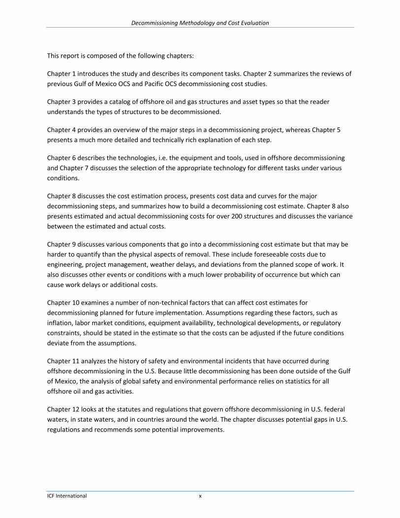
This report is composed of the following chapters:
Chapter 1 introduces the study and describes its component tasks. Chapter 2 summarizes the reviews of
previous Gulf of Mexico OCS and Pacific OCS decommissioning cost studies.
Chapter 3 provides a catalog of offshore oil and gas structures and asset types so that the reader
understands the types of structures to be decommissioned.
Chapter 4 provides an overview of the major steps in a decommissioning project, whereas Chapter 5
presents a much more detailed and technically rich explanation of each step.
Chapter 6 describes the technologies, i.e. the equipment and tools, used in offshore decommissioning
and Chapter 7 discusses the selection of the appropriate technology for different tasks under various
conditions.
Chapter 8 discusses the cost estimation process, presents cost data and curves for the major
decommissioning steps, and summarizes how to build a decommissioning cost estimate. Chapter 8 also
presents estimated and actual decommissioning costs for over 200 structures and discusses the variance
between the estimated and actual costs.
Chapter 9 discusses various components that go into a decommissioning cost estimate but that may be
harder to quantify than the physical aspects of removal. These include foreseeable costs due to
engineering, project management, weather delays, and deviations from the planned scope of work. It
also discusses other events or conditions with a much lower probability of occurrence but which can
cause work delays or additional costs.
Chapter 10 examines a number of non-technical factors that can affect cost estimates for
decommissioning planned for future implementation. Assumptions regarding these factors, such as
inflation, labor market conditions, equipment availability, technological developments, or regulatory
constraints, should be stated in the estimate so that the costs can be adjusted if the future conditions
deviate from the assumptions.
Chapter 11 analyzes the history of safety and environmental incidents that have occurred during
offshore decommissioning in the U.S. Because little decommissioning has been done outside of the Gulf
of Mexico, the analysis of global safety and environmental performance relies on statistics for all
offshore oil and gas activities.
Chapter 12 looks at the statutes and regulations that govern offshore decommissioning in U.S. federal
waters, in state waters, and in countries around the world. The chapter discusses potential gaps in U.S.
regulations and recommends some potential improvements.
Decommissioning Methodology and Cost Evaluation
ICF International xi
Conclusions
The decommissioning of offshore oil and gas facilities presents many challenges throughout all parts of
the operation. Development of new and innovative structures to explore and produce in deeper waters
has been followed by continued development of new methods and techniques to remove those facilities
when they reach the end of their productive lives. The historical performance of decommissioning
projects provides useful guidance in developing cost estimates for future projects. The uncertainties of
offshore work mean that cost estimates will never be perfect due to ocean and weather conditions
beyond the operator’s control, but a structured approach to cost estimation and periodic benchmarking
against actual projects affords the best approach for operators and for BSEE to determine reasonable
decommissioning cost estimates.

Decommissioning Methodology and Cost Evaluation
ICF International xii
Acronyms, Abbreviations, and Definitions
Acronym / Abbreviation Stands For
AHSV Anchor Handling Support Vessel
AHT Anchor Handling Tug
ANP Agência Nacional do Petróleo, Gás Natural e Biocombustíveis (Brazilian National Petroleum Agency)
ARO Asset Retirement Obligation
AWJ Abrasive Water Jet
BAST Best Available and Safest Technology
BOEM Bureau of Ocean Energy Management
BML or bml Below Mud Line
BOEMRE Bureau of Ocean Energy Management, Regulation and Enforcement
BOP Blowout Preventer
BOPE Blowout Prevention Equipment
BSEE Bureau of Safety and Environmental Enforcement
BTA Buoyancy Tank Assembly
CB Cargo Barge
CFR Code of Federal Regulations
CIBP Cast Iron Bridge Plug
C-NLOPB Canada-Newfoundland and Labrador Offshore Petroleum Board
CNSOPB Canada-Nova Scotia Offshore Petroleum Board
COG Center of Gravity
CT Compliant Tower
CVBS Controlled Variable Buoyancy System
DB Derrick Barge
DDCV Deep Draft Caisson Vessel
DEA Danish Energy Agency
DOI Department of the Interior
Downhole Refers to well formations, as in pumping flushed fluids downhole or into the well and its formations
DP Dynamically Positioned
Dry Tree A well with its wellhead located above the water surface
DSI Deep Sea Intervention vessel
DSV Dive Support Vessel

Decommissioning Methodology and Cost Evaluation
ICF International xiii
Acronym / Abbreviation Stands For
DWCS Diamond Wire Cutting System
E&PM Engineering & Project Management
EBW Exploding Bridge Wire
EIS/EIR Environmental Impact Statement/Environmental Impact Report
FPSO Floating Production Storage and Offloading Vessel
GOM Gulf of Mexico
HLV Heavy Lift Vessel
Hopping A HLV lifts the jacket partially out of water, secures it to the vessel, transports it to a shallower water depth, sets the jacket on the bottom and severs and removes the above the waterline section. The process is repeated until the jacket is completely removed.
HSE Health and Safety Executive, United Kingdom
IBU Intelligent Buoyancy Unit
IRM Inspection, Repair, and Maintenance
IRF International Regulator Forum
LB Lift Boat – numerical value after LB refers to the working depth in feet (LB 100)
Methodology The method of decommissioning, as in the overall process; e.g., completely remove the jacket. Also called process
Mob/Demob Mobilization/Demobilization
MODU Mobile Offshore Drilling Unit
MOPU Mobile Offshore Production Unit
MSV Multi-Service Vessel
MSV-T Multi-Service Vessel with Tower
MTLP Mini Tension Leg Platform
NEPA National Environmental Policy Act
NM Nautical Mile (approx. 6,076 feet or 1.15 miles)
NOPSEMA National Offshore Petroleum Safety and Environmental Management Authority, Australia
NTL Notice to Lessees and Operators
OCS Outer Continental Shelf
P&A Plug and Abandon
PAES® Platform Abandonment Estimating System
PEA Programmatic Environmental Assessment
PEIS Programmatic Environmental Impact Statement
Decommissioning Methodology and Cost Evaluation
ICF International xiv
Acronym / Abbreviation Stands For
Piece small Piece small is a decommissioning methodology to remove structures by cutting into pieces small enough to fit into regular waste containers, and are shipped to shore by standard supply vessels.
PL Pipeline
PLET Pipeline End Termination
PM Project Management
POCS Pacific Outer Continental Shelf
POOH Pull Out Of Hole
Process The overall decommissioning methodology
ROV Remotely Operated Vehicle
SAT Saturation Diving
SCSSV Surface Controlled Subsurface Safety Valve
SEMI Semi-submersible Platform
SILS® Subsea Intervention Lubricator System
Spread The particular assemblage of crew and equipment required to complete a particular task
SSCV Semi-submersible Crane Vessel
SSM State Supervision of Mines, The Netherlands
SSS Side-Scan Sonar
SSTI Subsea Tie-In (where a pipeline ties in or attaches to another pipeline as in a perpendicular or angled connection)
SSTMP Subsea Template
st Short Ton Unit
SUTA Subsea Umbilical Termination Assembly
SWED Shock Wave Enhancement Device
TAP Technology Assessment Programs
Technique The techniques used to accomplish the overall decommissioning methodology or process; e.g., remove the jacket by cutting into smaller pieces under water
Technology The resources used to perform the decommissioning technique; e.g., cutting the jacket underwater using divers or ROV with either diamond wire cutters, shears, etc.
TLP Tension Leg Platform
TSB TSB Offshore, Inc.
UTA Umbilical Termination Assembly
WD Water Depth in feet
Wet Tree A well with its wellhead located below the water surface
Decommissioning Methodology and Cost Evaluation
ICF International xv
Acronym / Abbreviation Stands For
WIV Well Intervention Vessel
WOC Wait on cement
WP Well Protector

Decommissioning Methodology and Cost Evaluation
ICF International xvi
Acknowledgments
ICF would like to recognize the governmental agencies and commercial firms that contributed
information for this report.
The International Regulators’ Forum (IRF) is a consortium of regulatory bodies that oversee health and
safety issues in the offshore upstream oil and gas industry. As part of this study, ICF reached out to all of
the IRF member agencies for their input on technical, financial, environmental, safety, and regulatory
issues associated with decommissioning offshore structures. In particular, we would like to thank the
following individuals for their contributions:
Jeremy Dunster, National Offshore Petroleum Safety and Environmental Management Authority
(NOPSEMA), Australia
Luciano da Silva Pinto Teixeira, Brazilian National Petroleum Agency (ANP), Brazil
Daniel Chicoyne, Canada-Newfoundland and Labrador Offshore Petroleum Board, (C-NLOPB),
Canada
Richard Loughery, Canada-Nova Scotia Offshore Petroleum Board, (CNSOPB), Canada
Hans Christian Langager, Danish Energy Agency (DEA), Denmark
Ivan Abdoellakhan, State Supervision of Mines (SSM), The Netherlands
Wayne Vernon, Department of Labour Workplace Services, New Zealand
Reidar Hamre, Petroleum Safety Authority Norway, Norway
Stewart Millar, The Health and Safety Executive (HSE), United Kingdom
As part of this study, we initiated outreach efforts to companies involved in decommissioning activities
to request that they share confidential information on techniques and costs. The confidentiality
agreements with the firms that contributed data preclude mentioning them by name, but the
comparisons between estimated and actual cost data would not have been possible without their input.
We thank them for their kind participation in this study.
ICF’s subcontractor, TSB Offshore, Inc., provided the bulk of the information on the technical aspects of
offshore decommissioning, generated the estimated decommissioning costs that made the estimated
vs. actual cost comparisons possible, and prepared large sections of this report.
Finally, we would like to thank the members of the BSEE project team that contributed to this study,
especially the Contracting Officer Herma Banks, the Contracting Officer’s Representative and Project
Manager Mohammad Ashfaq, and Subject Matter Experts and Reviewers Olivia Adrian, Keith Good,
Peter Hosch, Kathy Hoffman, and Joseph Levine. Their comments and reviews of the report during its
production added valuable insights from the regulator’s perspective, clarified technical details, and
greatly improved the final result.

Decommissioning Methodology and Cost Evaluation
ICF International 1-1
1. Introduction to the Decommissioning Methodology and Cost Evaluation Study The mission of the Bureau of Safety and Environmental Enforcement (BSEE) is to promote safety,
protect the environment, and conserve resources offshore through regulatory oversight and
enforcement. Through its Technology Assessment Programs (TAP), BSEE supports research related to
operational safety and pollution prevention to provide engineering support to BSEE decision makers, to
promote the use of Best Available and Safest Technologies (BAST), and to coordinate international
research. The objectives of this study, Decommissioning Methodology and Cost Evaluation, address each
of these research areas. This study has been prepared under BPA No. E13PA00010, Call Order No.
E14PB00056.
This report documents conventional domestic and global decommissioning and facility removal
techniques, the estimated and actual costs of those techniques, and the regulatory structures that
govern decommissioning and facility removal around the world. The study will improve BSEE’s ability to
determine the proper amount of supplemental bonding required to ensure compliance with
decommissioning requirements, will improve BSEE’s knowledge of current decommissioning methods
and equipment capabilities, and will document the safety and environmental performance of different
equipment and methods used globally during decommissioning and facility removal operations.
The technical approach framed the scope of work into eight tasks. Task 1 involved the review of
previous MMS decommissioning reports. Tasks 2, 3, and 4 involved the collection of data and the
analysis of activities related to estimated and actual costs, decommissioning methodologies and facility
removal techniques, safety incidents, and environmental incidents. Tasks 5, 6, and 7 involved
documenting the decommissioning decision process, cost estimation uncertainties and contingencies,
and non-technical cost factors. Task 8 evaluated BSEE regulations in comparison to other jurisdictions.

Decommissioning Methodology and Cost Evaluation
ICF International 2-1
2. Review of Previous Decommissioning Studies BSEE (and its predecessor MMS) perform periodic studies and publish reports describing the
technologies, methodologies, and costs associated with decommissioning offshore facilities. The intent
of BSEE is to update these reports every five years to incorporate new information that may result from
advances in technology, changes in market conditions, or new regulatory requirements. This section
summarizes the results of the reviews of the most recent previous reports for decommissioning in the
Gulf of Mexico and in the Pacific OCS region and identifies key aspects that have been improved in this
report.
2.1. Review of the 2009 GOM Study
The 2009 report “Gulf of Mexico Deep Water Decommissioning Study, Review of the State of the Art for
Removal of GOM US OCS Oil & Gas Facilities In Greater Than 400’ Water Depth”1 presented an overall
review of decommissioning approaches and costs. The report provided a solid background on the
variety and complexity of offshore decommissioning and the technology and methodology available.
The cost sections allowed the reader to piece together various costs and get an understanding or a
general estimate of the total cost for a particular type of structure with various specifics; e.g., the
estimated cost for a 4-pile platform in a particular water depth with a described number of wells and
with a specified number of pipelines.
The 2009 study focused only on GOM decommissioning techniques, whereas this study considered other
global and regional technologies and methodologies. This report also incorporates information on any
decommissioning methodologies, technologies and equipment in use since 2009. For example, ever
larger platforms, such as those in the Gulf of Thailand region where the jackets were installed by
launching off of a transport barge and where the decks were installed using a float-over method, will
require removal methods other than traditional derrick barge removal. This report also covers more
recently developed technologies such as the use of gel pigs, increased industry use of remotely operated
vehicles (ROVs), and advances in cold cutting methods and mechanical shearing.
The costs for various aspects of decommissioning were provided in separate sections in the 2009 report.
Although the report did allow the reader to understand the steps in the decommissioning process and to
understand the costs of each step, it was not designed to develop a total decommissioning cost for the
purpose of bonding estimates. The previous study did not provide a visual or descriptive path on how to
go about selecting the correct decommissioning method and associated resources nor did it provide an
example of how to use the report to derive a total cost for a particular facility. This report includes a
newly-developed matrix to guide the reader in the decision process of what methodologies to consider
and where to go in the report to find appropriate information and costs for those methodologies. It also
includes guidelines on the appropriate use and limitations of the cost data and cost formulas. The
1 Proserv Offshore (2009), “Gulf of Mexico Deep Water Decommissioning Study, Review of the State of the Art for Removal of GOM US OCS Oil & Gas Facilities In Greater Than 400’ Water Depth”, Final Report, MMS M09PC00004, Houston, TX.

Decommissioning Methodology and Cost Evaluation
ICF International 2-2
discussion of costs includes new or expanded material on dry tree platform wells, umbilical
abandonment, subsea structure decommissioning, and the uncertainties and contingencies associated
with decommissioning.
2.2. Review of the 2010 POCS Study
2.2.1. Overview
The 2010 report “Decommissioning Cost Update for Removing Pacific OCS Region Offshore Oil and Gas
Facilities, January 2010”2 presented a review of the decommissioning practices for the Pacific OCS region
oil and gas facilities and developed benchmark costs for decommissioning the facilities utilizing
conventional technology. The report included cost assessments specific to the Pacific Region operations
and included reviews of the availability and capability of derrick barges; support vessel services; well
plugging and abandonment services; abrasive, mechanical and explosive cutting services; disposal
options; and site clearance services available along the west coast of the U.S.
The Pacific OCS decommissioning cost report was updated in 20143. No decommissioning work has been
performed in the Pacific OCS region so, except for updates on the estimated costs, the structure and
content of the 2014 report is similar to its 2010 predecessor. Where relevant, the updated cost
information from the 2014 Pacific OCS report is used in this report.
2.2.2. Undeveloped Market
The 2010 report documented that no structures had been decommissioned in the Pacific OCS region and
that only 7 relatively small structures had been decommissioned in California state waters, with the last
decommissioning occurring in 1996. No additional structures have been decommissioned since 2010.
The future market for decommissioning is also small because there are only 23 platforms in the region.
Therefore, offshore decommissioning equipment is not normally available along the U.S. Pacific coast.
The market has limited access to standard offshore oilfield equipment and spreads, i.e. the particular
assemblage of crew and equipment required to complete a particular task. Local companies could be
utilized, but there would be a lack of synergy and experience in decommissioning. Well P&A spreads
exist in the California onshore region, but they are not easily converted to offshore operations as they
are truck mounted or diesel powered. The well P&A spreads would most likely be mobilized from the
GOM. These spreads will have the proper equipment and experience for these operations, but they may
lack equipment modifications required to meet the more stringent California emission requirements.
2 Proserv Offshore (2010), “Decommissioning Cost Update for Removing Pacific OCS Region Offshore Oil and Gas Facilities,
January 2010”, Volumes 1 and 2, MMS M09PC00024, Houston, TX. 3 TSB Offshore, Inc. (2014), “Decommissioning Cost Update for Pacific OCS Region Facilities”, Volumes 1 and 2, Houston, TX.

Decommissioning Methodology and Cost Evaluation
ICF International 2-3
Many standard decommissioning methodologies require the use of large derrick barges which may be
unavailable in or expensive to mobilize to the Pacific OCS region. Decommissioning operations on a
majority of the platforms will require the use of a dynamic positioning (DP) vessel which is not currently
available in the Pacific region and would have to be mobilized. Alternative methods and techniques may
be adopted for some platforms to cost effective decommissioning project.
Diving operations are performed frequently on the Pacific coast but these operations do not normally
include decommissioning operations. The majority of these diving operations involve standard platform
or pipeline work that occurs in shallow water.
2.2.3. Availability of Cost Data
The lack of recent decommissioning projects in the Pacific OCS region makes the acquisition of actual
decommissioning cost data difficult and requires more indirect methods to estimate costs. Local
companies are willing to discuss the costs of mobilizing equipment and personnel for operations,
however, advance mobilization costs are of limited use as mobilization costs can vary greatly due to
market influences and can change significantly over a short period of time.
The use of local service providers needs to be compared with the advantages of mobilizing crews and
equipment from the GOM. Mobilizing well P&A equipment and workforce from GOM is relatively
inexpensive compared to the total expected service cost for a single platform. Mobilizing a DB from
GOM or Asia is a significant cost component of the overall decommissioning process. For some of the
deeper platforms, this could be offset against the increased time on station in using a smaller DB in
combination with deep reach vessel approach (see 2014 Pacific OCS study). The 2014 Pacific OCS study
incorporated local resources rates for diving services, trawling services, and material disposal sites
whereas the remaining equipment and services not locally available were estimated as if they were
being mobilized from outside California.
The 2014 study verifies or updates the information on derrick barge availability, the current well
numbers and classifications, the pipeline and power cable inventories, conductor sizes and weights, and
recycling facility capabilities.
All costs in the 2014 report were updated to current market values or adjusted for past inflation rates.

Decommissioning Methodology and Cost Evaluation
ICF International 3-1
3. Structure and Asset Types The purpose of this section is to identify and categorize the various configurations of platforms. The
types of platforms that are classified in the BSEE database are listed below. This section provides
descriptions of each type of platform.
Caissons
Compliant Towers
Fixed Platforms
Floating Production, Storage, and Offloading (FPSO) vessels
Mobile Offshore Production Units (MOPU)
Mini Tension Leg Platforms (MTLP) / Tension Leg Platforms (TLP)
Semi-submersible Platforms (SEMI)
Spars
Well Protectors (WP)
Subsea Templates (SSTMP)
3.1. Caissons
Caissons are straight cylindrical or tapered steel pipes driven into the seabed that support a steel deck
above the waterline. The caisson can be the well conductor or one or more conductor(s) can be installed
inside or outside the caisson. The wellhead inside the conductor is typically connected by a pipeline to a
nearby production platform. Outside diameters can range from 30” for a shallow water straight caisson
or 96”-120” for tapered multi-well caissons in deeper water. The term “tapered” here is used to
describe a caisson that has a larger diameter in the lower portion than the upper section. The transition
or taper can be above or below the waterline. The caisson can be free-standing or supported by a cable
mooring system secured to piles driven into the seabed or supported with one or more piles driven at an
angle into the seabed and secured to the caisson, the later often called a braced caisson. BSEE files lists
total weights of (decommissioned) caisson structures from 30 to 544 tons including conductors and
from 25 to 502 without conductors. Typical deck dimensions can vary from 10’X10’ to 40’X45’.
According to BSEE database, the deepest caisson in the GOM is located in 173’ of water. Typical
caissons are illustrated in Figure 3-1 and Figure 3-2.

Decommissioning Methodology and Cost Evaluation
ICF International 3-2
Figure 3-1. Typical Caisson Platforms
Figure 3-2. Typical Caisson Platform Components

Decommissioning Methodology and Cost Evaluation
ICF International 3-3
3.2. Compliant Towers (CT)
A compliant tower (CT) is a fixed rig steel structure normally used for the offshore production of oil or
gas. The rig consists of narrow, flexible (compliant) steel lattice towers and a piled foundation
supporting a conventional deck for drilling and production operations. Compliant towers are designed to
sustain significant lateral deflections and forces, and are typically used in water depths ranging from
1,500 to 3,000 feet (450 to 900 m). According to the BSEE database the deepest CT in the GOM is
located in 1,754’ of water at VK-786-A, also known as Petronius. With the use of flex elements such as
flex legs or axial tubes, resonance is reduced and wave forces are de-amplified. This type of rig structure
can be configured to adapt to existing fabrication and installation equipment. Compared with floating
systems, such as tension-leg platforms and SPARs, the production risers are conventional and are
subjected to less structural demands and flexing. [1] However, because of cost, it becomes
uneconomical to build compliant towers in depths greater than 1,000 meters. In such a case a floating
production system is more appropriate, even with the increased cost of risers and mooring. Despite its
flexibility, the compliant tower system is strong enough to withstand hurricane conditions.
The first tower emerged in the early 1980s with the installation of Exxon's Lena oil platform. (Wikipedia)
Typical compliant towers are illustrated below in Figure 3-3.
Figure 3-3. Compliant Towers

Decommissioning Methodology and Cost Evaluation
ICF International 3-4
3.3. Fixed Platforms
Fixed platforms are built on concrete or steel legs, or both, anchored directly onto the seabed, and
support a deck with space for drilling rigs, production facilities and crew quarters. These platforms are
designed for long term use due to their immobility. Steel jackets are vertical sections made of tubular
steel members and are usually piled into the seabed. These platforms typically have 3 to 12 legs,
sometimes more, and are anchored to the seabed with piles driven through the legs or through external
skirt pile guides, as shown in Figure 3-4. The platforms usually include several decks - wellhead deck,
production deck, sump deck, main deck and a helideck. The platforms are used when there will be
production from wells. Wells may be centered on the platform or grouped to one side of the platform
to facilitate the use of a jackup rig or a drilling rig. The platforms typically contain 4 to 24, but sometimes
more, slots or openings where the wells may be drilled or conductors may be placed. The smaller fixed
platforms located in shallower waters are not designed to support the weight of a drilling or workover
rig, however the larger fixed platforms located in deeper waters are designed to support a drilling rig
capable of drilling to over 20,000’. For two-legged platforms in water depths from 12 to 60 ft, jacket
weights range from 10 to 5,000 tons and deck weights range from 30 to 50 tons. For eight-legged
platforms in water depths from 50 to 935 ft, jacket weights range from 227 to 20,400 tons and deck
weights range from 200 to 17,000 tons. Typical deck sizes range from 50’ x 50’ in shallow waters up to
75’ x 120’ in deep waters4. According to the BSEE database the deepest fixed platform in the GOM is
located in 1,353’ of water at GC-65-A, also known as Bullwinkle. The deepest fixed platform in the in the
Pacific OCS region is Exxon’s Harmony platform located in 1,198’ of water.
4 There is no offshore industry standard for deep water. The delineation depth varies by region and changes over time as
projects are developed in ever deeper waters. In the North Sea in the 1970s and 1980s, deep water would have been anything deeper than 100 ft to 700 ft. In 2008, MMS stated that the boundary between shallow water and deepwater can range from 656 ft to 1,500 ft and selected a delineation depth of 1,000 ft . We have not attempted to establish a definition of the boundary between shallow water and deep water and the term should be interpreted qualitatively throughout this report.

Decommissioning Methodology and Cost Evaluation
ICF International 3-5
Figure 3-4. Typical Fixed Platform
3.4. Mobile Offshore Production Units (MOPU)
A Mobile Offshore Production Unit (MOPU) is a movable structure that serves as a platform for well and
production operations. Although the floating platforms described below (FPSOs, TLPs, SEMIs, and Spars)
are sometimes considered MOPUs, this section is limited to the most common usage which pertains to a
static MOPU, typically a jack-up drilling rig. MOPUs have evolved from mobile drilling platforms to
become complete production facilities. They are often considered for marginal fields because of their
lower installation and removal costs.
A typical MOPU consists of a floating hull or platform with a large, flat deck area through which multiple,
extendable legs can be lowered to or into the seabed to lift the platform above the water level.
Foundation preparation to support the legs may be necessary. A MOPU usually has no propulsion
system; it is floated into position by tugs. Once in place, a MOPU functions much like a fixed platform.
MOPUs are most commonly used in shallower waters but some have been designed to work in water
depths of over 500 feet.
3.5. Floating Production, Storage, and Offloading (FPSO) Vessels
Floating production, storage, and offloading (FPSO) are large ships moored to a location for a long
period and equipped with a variety of processing facilities to separate oil, gas and water. The FPSO
allows oil companies to produce oil in remote areas and in deeper water than would have been
economically possible with other technology, like fixed platforms. The FPSO’s do not drill for oil or gas,

Decommissioning Methodology and Cost Evaluation
ICF International 3-6
but are designed to process and store hydrocarbons produced by nearby platforms or subsea fields until
the product can be offloaded onto a tanker or transported through a pipeline. Typical FPSOs are
illustrated in Figure 3-5and Figure 3-6.
Figure 3-5. Typical FPSO
Figure 3-6. Representative FPSO’s
3.6. Tension Leg Platforms (TLP) / Mini Tension Leg Platforms (MTLP)
Tension leg platforms (TLPs) are buoyant production multihull steel floating platforms vertically moored
to the seafloor by a group of tendons to minimize vertical movement of the structure. The multihull
supports a steel deck and equipment. The group of tendons at each corner of the structure is called a
tension leg. A buoyant hull supports the platform's topsides and a mooring system keeps the TLP in

Decommissioning Methodology and Cost Evaluation
ICF International 3-7
place. The mooring system may be steel or polymer cables, chains, rigid pipe or a combination of the
same, all secured to piles secured to the seabed. The buoyancy of the platform’s hull offsets the weight
of the platform and maintains tension in clusters of tendons or tension legs that secure the structure to
the foundation. The foundation consists of concrete or steel piles driven into the seabed. One common
configuration uses four concrete piles with dimensions of 8’ in diameter and 360’ in length to anchor
each tension leg, totaling 16 concrete piles. The typical deck surface of the facility covers around 65,000
sq/ft and, depending on the size and activity being performed onboard a TLP, the living quarters can
house up to 100 people.
Mini TLPs are a smaller version of TLPs and typically contain a single vertical steel hull supporting a steel
deck and equipment. Pontoons located on the hull bottom are used to float the hull to the final
installation location offshore. The pontoons are anchored to a mooring system similar to TLPs and can
also be used as utility, satellite or early production platforms for larger deep water discoveries.
Dry tree wells are common on TLPs because of the limited vertical movement on the platforms. The
platforms can have 50 well slots with provisions for satellite subsea well tiebacks. Pipelines for the TLP
are the same as pipelines used for conventional platforms with diameters up to approximately 18” for
oil and 14” for gas. A well’s export pipeline will often connect to another pipeline for transport to shore.
According to the BSEE database, the deepest TLP platform in the GOM is located in 4,670’ of water at
GB-783-A, also known as Magnolia and the deepest MTLP is located in 4,250’ of water at GC-613-A, also
known as Neptune. Typical TLP platforms are illustrated in Figure 3-7 and Figure 3-8.
Figure 3-7. Typical TLP (MC-807-A)

Decommissioning Methodology and Cost Evaluation
ICF International 3-8
Figure 3-8. Representative TLP’s
3.7. Semi-submersible Platforms (SEMI)
Semi-submersible platforms are floating structures that have submerged columns or hulls that are
ballasted to maintain stability. The hulls have sufficient buoyancy to cause the structure to float and the
submerged ballast keeps the structure upright. The platform can be lowered or raised by altering the
amount of water in buoyancy tanks. Semi-submersibles remain on location either by mooring lines
anchored to the seafloor or by dynamic positioning systems. They are used for both exploratory and
development drilling and can be moved from place to place. According to the BSEE database the
deepest Semi-submersible in the GOM is located in 8,000’ of water at MC-920-A, also known as
Independence. Typical semi-submersibles are illustrated in Figure 3-9 and Figure 3-10, platforms #7 and
#8 are types of Semi-submersibles.

Decommissioning Methodology and Cost Evaluation
ICF International 3-9
Figure 3-9. Representative Semi-submersible Platforms
Figure 3-10. Typical Semi-submersible
3.8. Spars
Spar platforms are similar to semi-submersibles in that they are floating platforms, but they differ in that
they have a single ballasted structure for stability and buoyancy rather than multiple submerged
columns or hulls. This structure may be a single large cylinder or may comprise a shorter cylinder for
buoyancy connected by a truss to a deeper ballasted tank. Similar to an iceberg, the majority of a spar
facility is located beneath the water's surface, providing the facility increased stability. Spars are
moored to the seabed with conventional mooring lines. A spar may be more economical to build than a
TLP for small and medium sized rigs. A spar also has the ability to move horizontally to position itself

Decommissioning Methodology and Cost Evaluation
ICF International 3-10
over wells at some distance from the main platform location by adjusting the mooring line tensions
using chain jacks. According to the BSEE database the deepest Spar in the GOM is located in 7,835’ of
water at AC-857-A, also known as Perdido. Typical spars are illustrated in Figure 3-11 and Figure 3-12.
Figure 3-11. Representative Spars
Figure 3-12. Typical Spar (MC-773-A)
3.9. Well Protectors (WP)
Well protectors are multi-legged structures that are used as temporary or permanent means of
supporting conductors during or after drilling and minimal equipment (heaters, small separators,
telemetry, etc.). They are typically used in conjunction with manifold/production facilities when several
wells are needed over a large area. The platforms can support single or multiple wells and will typically
have one to four slots. The wells are typically drilled using a barge, jackup, or submersible rig. The
platforms are configured to provide limited access for support of drilling and workover operations with
Decommissioning Methodology and Cost Evaluation
ICF International 3-11
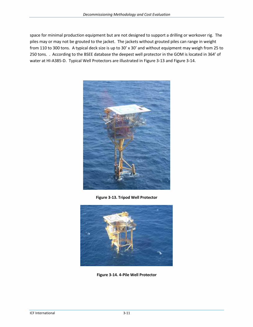
space for minimal production equipment but are not designed to support a drilling or workover rig. The
piles may or may not be grouted to the jacket. The jackets without grouted piles can range in weight
from 110 to 300 tons. A typical deck size is up to 30’ x 30’ and without equipment may weigh from 25 to
250 tons. . According to the BSEE database the deepest well protector in the GOM is located in 364’ of
water at HI-A385-D. Typical Well Protectors are illustrated in Figure 3-13 and Figure 3-14.
Figure 3-13. Tripod Well Protector
Figure 3-14. 4-Pile Well Protector

Decommissioning Methodology and Cost Evaluation
ICF International 3-12
3.10. Subsea Templates (SSTMP)
A typical subsea template includes the following equipment; subsea manifolds, Pipeline End
Terminations (PLETs), jumpers, subsea trees, and Umbilical Termination Assemblies (UTAs). Each piece
of equipment is described below. Subsea templates typically cannot be installed in water depths less
than 100’ due to the height of the subsea equipment, as navigation clearance must be maintained.
Figure 3-15 shows a diagram of a typical subsea template layout
Figure 3-15. Typical Subsea Template Layout
3.10.1. Subsea Manifolds
A subsea manifold is an arrangement of pipelines and valves designed to combine, distribute, control
and monitor fluids. Subsea manifolds are installed within an arrangement of wells to collect production
from all of the wells and are typically anchored with piles driven into the seafloor.
3.10.2. Pipeline End Termination (PLET)
PLETs are designed to connect the end of a pipeline to subsea manifolds or subsea trees. A typical PLET
will have a single hub with either a manual or remotely actuated valve installed. Unlike subsea
manifolds, PLETs have pig launching and receiving capabilities.
3.10.3. Jumper
A jumper is a short piece of pipe typically up to 160’ in length that is used to send production fluid
between two subsea components, for example, from 1) a subsea tree to a subsea manifold 2) a subsea
manifold to another subsea manifold, 3) a subsea manifold to a PLET, 4) a PLET to the pipeline or 5) a
SUTA to the umbilical. Jumpers are assigned segment numbers during permitting, with the exception of
#s 4 and 5 above as they are considered to be the same segment number as the pipeline or umbilical to
which they are attached.

Decommissioning Methodology and Cost Evaluation
ICF International 3-13
3.10.4. Subsea Tree
A subsea tree is an arrangement of fittings, piping and valves that is located on top of a wellhead. The
valves can be operated by a diver, ROV or remote control.
3.10.5. Umbilical
An umbilical includes a bundle of tubing, piping and electrical connections. Umbilicals are used to
transmit fluids, electrical power, and control signals from the topside of a platform to subsea equipment
to operate valves and power sensors. Umbilicals also return temperature, pressure, and other sensor
information from the wells and subsea equipment to the operators on the platform.
3.10.6. Subsea Umbilical Termination Assembly (SUTA)
A SUTA is the subsea interface for an umbilical and serves as the delivery point for the required fluids
and electric currents to operate the subsea equipment.
3.11. Distribution of Structure Types
Table 3-1 shows the distribution of the 2,475 Major Asset Platforms located in the Gulf of Mexico (GOM)
identified in the BSEE database. Numerous public sources including BSEE and other websites were
visited to obtain information on the GOM major assets and characteristics of the various types of
platforms. Some of the sources of information provided conflicting data and the data believed to be
most reliable information was used in this study. Figure 3-16 shows the history of platform installation
in the GOM, including the evolution of structure types as operators moved into deeper and deeper
water.
Table 3-1. Existing Structures in the GOM
Structure Type 0’ to 400’ 401’ to 800’ 801’ to 2,000’ > 2,000’+ Caisson 578 3 0 0
CT 0 0 3 0 Fixed 1,586 44 8 0
FPSO 0 0 0 1 MOPU 0 0 0 1 MTLP 0 0 1 3 SEMI 0 0 0 9 Spar 0 0 1 15 TLP 0 0 2 10
WP 210 0 0 0 Totals 2,374 47 15 39

Decommissioning Methodology and Cost Evaluation
ICF International 3-14
Figure 3-16. History of Platform Installation in the GOM

Decommissioning Methodology and Cost Evaluation
ICF International 4-1
4. The Decommissioning Process This section provides an overview of the decommissioning process from planning to offshore operations
for well, pipeline and platform abandonment.
To date, nearly all decommissioning activities in the GOM have been on structures in water depths
<400’. With the exception of a few isolated decommissioning platforms globally, no other
decommissioning activity has occurred. As decommissioning activities move into deeper water and to
tensioned and moored structures, some of the current technology may need modification or may prove
inadequate. This section focuses on the mature areas of development and present emerging
developments along with the latest development in technologies and technique will be discussed in
section 5.0 of the report.
4.1. Pre-job Activities
Before any physical decommissioning work can commence, a number of pre-job activities must be
completed. The pre-job components of a decommissioning program consist of the following activities:
Decommissioning Planning
Decommissioning Engineering
Permitting
Bidding
Pre-job Meetings
4.1.1. Decommissioning Planning
Decommissioning planning includes gathering and reviewing platform, pipeline and well information,
preparing a decommissioning estimate, and performing an inspection of the platform. This is the initial
phase of the decommissioning project. All information available for each platform to be
decommissioned (structural drawings, installation records, process flow diagrams, pipeline maps, etc.) is
first gathered and reviewed. Based on the information retrieved, various removal methods (i.e.,
Complete Removal, Partial Removal, and Remote Reefing) may be evaluated. An Approval for
Expenditure (AFE) cost estimate for each platform is developed and submitted to the platform owner for
approval. In cases where multiple platforms are to be decommissioned, this AFE will consider grouping
the platforms to realize any economies of scale. In some instances different operators will join together
to share the same deep water equipment for a multiple platform decommissioning program. All
assumptions made are noted on the AFE. Concurrently, a detailed project schedule is developed.
After the AFE is approved, the platform is inspected above and under water to appraise the overall
platform condition, drilling and production deck dimensions, equipment location, pad eyes, risers, etc.
A detailed inspection punch list is submitted to and agreed upon with the platform owner prior to these
inspections.

Decommissioning Methodology and Cost Evaluation
ICF International 4-2
TSB recommends conducting a pre-contracting underwater survey of the jacket and seafloor for larger
and older platforms. The dive crew would survey the sea floor for debris that would hamper the
platform removal and inspect the jacket for flooded and/or damaged members and conductors.
For conventional steel-jacket platforms located in shallow5 depths, TSB recommends a six-month lead-
time for decommissioning planning. However, deep water decommissioning planning requires a longer
lead-time because of the limited availability of deep water removal equipment. Therefore, a minimum
of two years lead-time is recommended for planning the decommissioning of deep water platforms. For
complete removal, equipment contracting alone will require at least one to two years lead time.
4.1.2. Decommissioning Engineering
Detailed engineering is carried out to determine the specific procedures, vessels, equipment, and
manpower that may be used in the decommissioning process. The analyses include the determination of
the weights of individually removed pieces, crane and vessel capacities, and the structural stability of
the platform at all stages of the dismantling process.
A project management group is established with owner and/or operator personnel and may also include
an outside project management consultant. The contractor will join the group after bids are reviewed
and the contractor is selected.
A major consideration is the ability to safely remove platform components and sections. Deck and jacket
actual weights, the center of gravity, and the center of buoyancy are needed for the platforms and
major subsea equipment. Lift analyses are developed by structural engineers; all calculations are
reviewed and approved by the project manager.
Additionally, pipeline operators of connecting pipelines are contacted to coordinate pipeline
decommissioning activities.
4.1.3. Permitting
Permits required by the Bureau of Safety and Environmental Enforcement (BSEE) for the
decommissioning of offshore structures are as follows:
Well P&A Sundry Notices and Procedures
Pipeline Abandonment Permits
Platform Removal Permits
Reefing Permits (if applicable)
Incidental Take Statement
5 Definitions for water depth variations -- Shallow water – less than 50 ft, Standard water - 51 ft – 399 ft, Deep water – greater than 400 ft
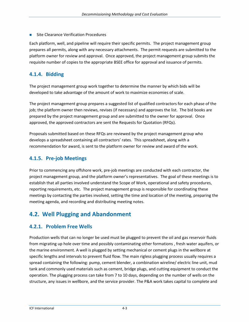
Decommissioning Methodology and Cost Evaluation
ICF International 4-3
Site Clearance Verification Procedures
Each platform, well, and pipeline will require their specific permits. The project management group
prepares all permits, along with any necessary attachments. The permit requests are submitted to the
platform owner for review and approval. Once approved, the project management group submits the
requisite number of copies to the appropriate BSEE office for approval and issuance of permits.
4.1.4. Bidding
The project management group work together to determine the manner by which bids will be
developed to take advantage of the amount of work to maximize economies of scale.
The project management group prepares a suggested list of qualified contractors for each phase of the
job; the platform owner then reviews, revises (if necessary) and approves the list. The bid books are
prepared by the project management group and are submitted to the owner for approval. Once
approved, the approved contractors are sent the Requests for Quotation (RFQs).
Proposals submitted based on these RFQs are reviewed by the project management group who
develops a spreadsheet containing all contractors’ rates. This spreadsheet, along with a
recommendation for award, is sent to the platform owner for review and award of the work.
4.1.5. Pre-job Meetings
Prior to commencing any offshore work, pre-job meetings are conducted with each contractor, the
project management group, and the platform owner’s representatives. The goal of these meetings is to
establish that all parties involved understand the Scope of Work, operational and safety procedures,
reporting requirements, etc. The project management group is responsible for coordinating these
meetings by contacting the parties involved, setting the time and location of the meeting, preparing the
meeting agenda, and recording and distributing meeting notes.
4.2. Well Plugging and Abandonment
4.2.1. Problem Free Wells
Production wells that can no longer be used must be plugged to prevent the oil and gas reservoir fluids
from migrating up hole over time and possibly contaminating other formations , fresh water aquifers, or
the marine environment. A well is plugged by setting mechanical or cement plugs in the wellbore at
specific lengths and intervals to prevent fluid flow. The main rigless plugging process usually requires a
spread containing the following: pump, cement blender, a combination wireline/ electric line unit, mud
tank and commonly used materials such as cement, bridge plugs, and cutting equipment to conduct the
operation. The plugging process can take from 7 to 10 days, depending on the number of wells on the
structure, any issues in wellbore, and the service provider. The P&A work takes capital to complete and

Decommissioning Methodology and Cost Evaluation
ICF International 4-4
provides no return on the investment for the oil companies, so most wells are plugged at the lowest cost
possible following the minimum requirements set forth by the oil and gas regulators.
After production ceases from the platform, the wells are plugged and abandoned6. Once the well P&A
crew mobilizes and sets up on the platform, it performs diagnostics (establishes injection rates into the
well for killing fluids and cement runs and runs wireline surveys) to determine the status of each well.
P&A operations include the following steps to properly seal the well, remove well components, and
isolate all water-bearing and commercial producing zones:
Squeeze all perforations with cement.
Set intermediate plugs.
Cut and remove the tubing at approximately 300 ft below the mudline to allow space for a 200 ft.
cement plug.
If the production or surface casing annuli are not grouted, then a cement plug is set to isolate the
casing.
A Cast Iron Bridge Plug (CIBP) is set above the point the tubing is cut.
A 200 ft balanced cement plug is set above the CIBP and tested.
Once tested, all casing and conductors are cut at 15 ft below the mudline.
Alternatively, a typical well temporary abandonment (T&A) is performed where all plugs are set and the
conductor and any grouted casings are severed and removed during or prior to platform removal
operations.
During well abandonment projects it is imperative that adequate seals are placed in the wellbore to
permanently seal the well. This is a challenge in deep water wells especially in subsea wet trees. The
challenge is greatly increased for wellheads without access fittings to all casing annulus sections.
Wellheads should be designed with full access to all casing strings which will reduce well
decommissioning costs.
Another decommissioning cost savings well design factor is to place the production packer below the
top of cement in the production casing. The packer should be placed far enough below to allow
sufficient space for the cement plugs needed to eventually seal off the well.
Ideally all permeable zones above the production casing show should be sealed off with cement during
the drilling of the well. For the most part it is easier and less expensive to seal off these zones during
the well drilling operation than during a decommissioning project.
6 Well plugging and abandonment (P&A) is common industry terminology for permanently decommissioning wells. Although
some components such as tubing or casing may be physically removed, as opposed to abandoned in place, the term “abandonment” is most frequently used for well decommissioning activities.

Decommissioning Methodology and Cost Evaluation
ICF International 4-5
4.2.2. Problem Wells
A problem well can be any well that does not have sufficient integrity to continue producing oil and gas
due to factors such as those shown below:
Improper cementing of casings and annuli which can develop bubbles or fluid leakage,
Damaged or collapsed casing and tubing,
Sustained casing pressure which requires the use of expensive intervention methods such as
snubbing or hydraulic workover,
Obstructions in the tubing, e.g., stuck plugs or lost tools from previous operations, which require
fishing operations,
Paraffin scale or sand development in the tubing which requires coil tubing intervention to clean out
the wellbore,
Frozen valves on the wellhead,
Presence of H2S or CO2 production,
Displacement of heavy water or oil base mud, or
Heavily deviated wells that require special tools such as a roller stem for operation.
4.3. Pipeline Decommissioning
Pipelines may be either removed or, with a waiver, abandoned in place. Prior to removal, pipelines must
be pigged and flushed with water. Pipelines abandoned in place must be flushed, filled with seawater,
cut, and plugged with the ends buried at least 3 feet. Pipelines that are abandoned in place must not
pose hazards to navigation hazards, commercial fishing, or other marine activities.
4.4. Platform Decommissioning
The platform removal process is inclusive of the following operations; platform cleaning, conductor
removal, deck and equipment removal, jacket or hull removal and disposal. The description of each
operation is described below.
4.4.1. Platform Preparation and Cleaning
Platform preparation includes the procedures associated with shutting down and preparing the facility
for removal. Level I topside inspections and Level II underwater inspections are generally conducted to
determine the condition of the structure and to identify any problems for removal. Divers will perform
the underwater inspection in water depths ranging from 0’ to 200’ and remotely operated vehicles
(ROV’s) will perform the underwater inspections from water depths ranging from 200’ to 1,200’. After
the inspections have been completed, a crew paid on a day rate or fixed price bid prepares the structure
for decommissioning after the wells have been permanently plugged and abandoned and the pipelines
have been abandoned.
Decommissioning Methodology and Cost Evaluation
ICF International 4-6
On the surface (topside of the platforms), the work includes the flushing/cleaning and degassing/purging
of tanks, processing equipment and piping, disposal of residual hydrocarbons, removal of platform
equipment, cutting of piping and cables between deck modules, separation of modules into individual
units, installation of padeyes for deck module lifting, removal of obstructions to lifting, and structural
reinforcement. Topside preparation also includes severing connections between the deck and jacket
and verifying that all pipelines have had a section of pipe removed between the deck and jacket. If not,
the crew removes a section at the +10 elevation.
Where permitted, marine growth can be removed from the structure at sea; otherwise it produces very
foul odor during jacket disposal onshore. Shell mounds arise from the shedding or removal of the shells
of mussels, barnacles, rock scallops and other invertebrates that attach themselves to platform jackets.
Removal of marine growth at sea may contribute to the creation or expansion of shell mounds. A 2014
BOEM study concluded that the chemical concentrations in shell mounds pose no appreciable risk to
marine biota. Shell mounds are defined as obstructions in 30 CFR 250.1700; 30 CFR 250.1703 requires
the clearance of all obstructions. However, the need for shell mound removal is often reviewed on a
case-by-case basis.
The key factors affecting the cost of platform preparation include structure size and complexity,
topsides equipment (especially the amount of processing equipment), and age of the facility. The costs
can vary widely depending on the type of facility, removal procedures, and transportation and disposal
options.
4.4.2. Conductor Severing and Removal
The conductors can be removed prior to the HLV arrival or removed during platform decommissioning
operations with the HLV. All conductors are severed and completely removed at least 15 feet below the
mudline. The conductors are severed by one of the following methods:
Explosives
Abrasive Cutting
Mechanical Cutting
Diamond Wire Cutting
One or a combination of the following are used to pull the conductors:
Casing jacks
Platform’s drilling rig, if present
Platform crane
The crane on a HLV
Regardless of the lifting device, the removal sequence is the same. The conductor is pulled upward until
a 40-foot section is exposed. The conductor is cut using external mechanical cutters or possibly the
threaded connections are unscrewed. The cut section is then removed by the drilling rig or platform
crane and placed on a workboat, cargo barge or on the deck away from the work area. This procedure

Decommissioning Methodology and Cost Evaluation
ICF International 4-7
(pull, cut and remove) is repeated until the entire conductor is removed. The jacks onboard may not be
able to pull the combined weight if the conductor is grouted. In this case, a rig or crane is used until the
jacks can pull the weight of the conductor by themselves.
4.4.3. Removing Deck and Modules
Topsides removal follows the installation process in reverse sequence. Some deck removals will require
that modules are removed and placed on a cargo barge. The module is secured by welding pieces of
steel pipe (or plate) from the module to the deck of the cargo barge. If the deck is planned to be lifted in
multiple sections; e.g., removing two 4-legged section from an 8-legged deck, the deck is severed into
two section, the connection between the deck and jacket are severed and each section is lifted and
placed on a cargo barge and the legs are secured to the deck by welding.
One of the emerging decommissioning processes will be deck removal by the floatover method. This has
not been a method of installation or removal because HLVs of sufficient size have not existed until
recently. A specially designed vessel was used that can be partially submerged by ballasting and raised
by deballasting as shown in Figure 4-1 and Figure 4-2.
Figure 4-1. Deck Ready to Be Installed

Decommissioning Methodology and Cost Evaluation
ICF International 4-8
Figure 4-2. Deck Installed
4.4.4. Jacket / Hull Removal
Platform jackets or hulls may be decommissioned using one of the following alternatives - complete
removal, partial removal, or remote reefing. These alternatives vary only in the methods used to remove
the jacket or hull. For any given platform type, the platform removal preparation, well P&A, and pipeline
decommissioning are the same for all removal alternatives.
4.4.4.1. Fixed Structures, Complete Removal
Jacket removal involves separating the structure from its foundation and transporting it in whole or in
pieces to a scrap yard where it is cut up and recycled.
The majority of jackets are separated from their foundations with explosives although non-explosive
removal techniques are becoming more common.
When explosives are used during a platform removal, regulations require a pre-blast aerial survey for
resident marine mammals immediately prior to the explosive detonation. This survey is performed
using a helicopter with a National Marine Fisheries Service (NMFS) observer onboard to determine if
there are marine mammals in the area. If marine mammals are found near the platform, the explosive
detonation is delayed. The detonation delay will last until the marine mammals are safely out of the
area. Once the explosives are detonated, a post-blast aerial survey is conducted.

Decommissioning Methodology and Cost Evaluation
ICF International 4-9
Explosives are placed in the main piles and skirt piles at least 15 ft below the mudline. If the mud plug
inside the piles is not deep enough to allow the explosive charge to be placed at the required depth, the
mud plug is jet/air lifted.
If it is necessary to reduce the jacket weight because the HLV does not have sufficient lifting capacity to
overcome the jacket weight and bottom friction, the severed jacket is made buoyant to reduce the
effective weight. To maximize buoyancy, closure plates are welded on the top of each pipe pile and
water is forced out using compressed air. A hose from an air compressor is connected to a valve on each
closure plate. The valve is opened and compressed air is forced into the piles. As the air pressure inside
a pile increases, the water is forced out of the bottom of the pile where it was severed, deballasting the
pile. When all of the water has been displaced from a pile, air bubbles appear on the surface of the
water near the jacket. After deballasting the jacket, it is lifted off the sea floor by the HLV. The jacket is
loaded onto a cargo barge if possible and transported to shore for disposal.
If the jacket is too large for loading on a cargo barge, the jacket is towed to shallower water. Although
this method, also called jacket hopping, has only been used rarely to date, it is being considered for
larger jackets because it allows the use of smaller, less expensive, and more available HLVs. The jacket is
supported by the HLV's crane and swung to the stern of the HLV. Rope hawsers are passed around two
of the jacket legs and secured to the stern of the HLV. The jacket is then boomed away from the stern of
the HLV until the hawsers are tight. The rope hawsers keep the jacket from swinging and being pulled
out of the boom radius by its movement through the water. The HLV's anchors are shifted and the
jacket is towed to shallower water.
At the new location, the jacket is ballasted and set on the sea floor. The water depth at the new
location is such that the elevation to be cut is several feet above the water. Welders set up scaffolds
around the jacket legs and begin cutting the jacket legs. Additionally, larger jackets may be cut in half
vertically to create two 4-leg sections or three 4-leg sections. The diagonal braces running between
each set of rows are cut.
After the legs and piles have been cut and the diagonal braces removed, the jacket section is rigged,
lifted, and sea-fastened on a cargo barge. For an eight-leg jacket, two four-leg sections are removed at
the bottom elevations. The cargo barge is then sent to the onshore disposal yard.
At times, the jacket is severed at multiple elevations because of its dimensions. The jacket is
deballasted, picked up, towed to shallower water, set, cut in two (vertically), and removed in sections.
This procedure is repeated until the jacket is completely removed and placed on cargo barges. Each
time the jacket is moved, the HLV’s anchors are repositioned.
4.4.4.2. Fixed Structures, Partial Removal
This scenario involves removing only the top section of the jacket. The jacket’s legs are severed as in
complete removal, except that the cuts are made at the top of the portion of the jacket that will remain
in place. The remaining structure must not become a marine obstruction. This removed section of the

Decommissioning Methodology and Cost Evaluation
ICF International 4-10
jacket will either be transported to shore for disposal or reefed in place or at another approved reef
location.
4.4.4.3. Fixed Structures, Reefing
After the topsides are removed the jacket is severed as in the complete removal method. If the jacket is
to be transported to an alternate reef site, the jacket is then made buoyant as in the complete removal
method.
Reefing may involve complete or partial removal of the jackets. Structures may be reefed in place or
reefed at another approved location. The jackets are severed below the mudline (for complete removal)
or severed at some partial depth (for partial removal) as described above.
Reefing the jacket in place involves preparing the jacket so that it can be toppled whole or in sections by
a tug. For partial removal, the top portion of the jacket is cut into sections that can be toppled. All cuts
are performed before the vessel (e.g., a large tug, approximately 12,000 hp) arrives on site to minimize
the amount of time the tug is used. Additionally, rigging is set up in advance of the tug’s arrival and is
designed to release once the jacket or jacket sections topple over. A large jacket may be toppled in
multiple sections.
If the jacket is reefed at an alternate approved reef site, the jacket is transported to the site by the HLV
or by pull tugs. At the reef site, the jacket is lowered by ballasting the piles and the base is set on the sea
floor. The jacket is pulled over and left on its side at the reef location with a marker buoy placed on
location above the jacket.
4.4.4.4. Floating Structures
Floating structures are moored to piles installed in the seabed with steel pipe, steel or polymer cables,
steel chains, or a combination thereof. The mooring lines are released from the hull and the hull is
towed to a shore disposal facility. The mooring lines are severed from the anchor piles and removed.
Tensioned or moored structures (TLPs, FPSOs, Spars, SEMIs) are not candidates for partial removal and
are removed completely. Spars have been considered for reefing removal as in the recent reefing of the
Red Hawk. The difficulty in removing spars completely is managing the installed ballast, which is often
steel and ore that turns into a solid or concrete-like material that cannot be removed. Other tensioned
or moored hulls could be considered for reefing much in the way that ships are sunk off the coast.
4.5. Disposal
The cargo barge transports the deck and modules to a scrap yard. The modules may be lifted with
cranes or skidded off the barge to the yard. Once the modules have been removed from the barge, the
deck is skidded off the barge to the yard. All of the structural components and modules are cut into

Decommissioning Methodology and Cost Evaluation
ICF International 4-11
small pieces and disposed of as scrap unless the deck will be reused. The production equipment is
salvaged for reuse whenever possible.
4.6. Site Clearance and Verification
Following removal, the platform site and any location where the jacket is cut will be cleared of debris
and verified that it has been cleared. The site is cleared by the use of trawlers dragging nets across the
bottom in a recorded grid pattern of specified dimensions or by the use of other authorized methods
per 30 CFR 250.1740. Service providers follow NTL No. 98-26 Minimum Interim Requirements for Site
Clearance (and Verification) of Abandoned Oil and Gas Structures in the GOM. Any trash that is retrieved
from the sea floor is transported to shore for proper disposal.
4.7. Post-job Activities
Each decommissioning phase requires a report be submitted to BSEE. These reports are submitted to
the platform owner for review and approval. Once approved, the project management group submits
the reports to the appropriate BSEE office.
Decommissioning Methodology and Cost Evaluation
ICF International 5-1
5. Facility Decommissioning Techniques and Methodology
5.1. Well Plugging and Abandonment
Well plugging and abandonment involves isolating hydrocarbon bearing zones from water bearing
zones, creating barriers to prevent leakage of hydrocarbons from the well into the sea, and removing
well components.
5.1.1. Planning for Well Abandonment
When planning to plug and abandon a well, the following data should be collected and stored in a
database (by either the well operator or the company performing the abandonment) for current and
future well abandonment programs:
Present well schematic
Well completion information
Well test report
Bottom hole pressure survey report
Recent wireline reports
Well head and tree details
Tubing details
Casing details and cementing information for each string
Directional survey and casing collar log
5.1.2. Isolating Well Zones
A typical well consists of a series of concentric pipes or casings that are used to support the hole, access
the well and oil and gas bearing formations, and convey fluids. Upon abandonment, the flow pathways
used to extract the hydrocarbons must be sealed to prevent future flow and leakage. Different sections
of the well require different isolation techniques, as detailed below. (Also see 30 CFR 250.1715)
5.1.2.1. Zone in open hole
A cement plug is set at least 100’ below the bottom to at least 100’ above the top of oil, gas, and or
fresh water formation to isolate fluids in the strata
5.1.2.2. Open hole below casing
A cement plug is set with displacement method at least 100’ above and 100’ below the deepest
casing shoe;
A cement retainer or plug needs to be set within 50’ to 100’ above the casing shoe and a cement
plug that extends at least 100’ below the casing shoe and at least 50’ above the retainer; or
Decommissioning Methodology and Cost Evaluation
ICF International 5-2
A mechanical bridge plug needs to be set within 50’ to 100’ above the casing shoe with 50 feet of
cement on top of the bridge plug.
5.1.2.3. Perforated zone
A method to squeeze cement used to isolate all perforations. Cement squeezing involves injecting
cement slurry under pressure to fill all target voids, in this case the perforations in the well casing
and voids in the surrounding formation.
A cement plug (displaced) is set by the displacement method to at least 100 feet above to 100 feet
below the perforated interval, or down to a casing plug, whichever is less.
A cement plug (displaced) at least 200 feet in length, set by the displacement method, with the
bottom of the plug no more than 100 feet above the perforated interval.
If unable to squeeze perforations, a cement retainer or thru tubing bridge plug with effective back-
pressure control is set 50 to 100 feet above the top of the perforated interval, and a cement plug is
then squeezed below the retainer that extends at least 100 feet below the bottom of the perforated
interval and at least 50 feet on top of the retainer or tubing bridge plug.
A tubing plug is set no more than 100 feet above the perforated interval and is topped with a
sufficient volume of cement to extend at least 100 feet above the uppermost packer in the wellbore
and with at least 300 feet of cement in the casing annulus immediately above the packer.
5.1.2.4. Casing stub with the stub end within the casing
A cement plug is set at least 100 feet above and below the stub end.
A cement retainer or bridge plug is set within 50 to 100 feet above the stub end with at least 50 feet
of cement on top of the retainer or bridge plug.
A cement plug at least 200 feet long with bottom no more than 100 feet above the stub end.
5.1.2.5. Annular space that permits flow to the mud line
A cement plug at least 200 feet long is set in the annular space. For a well completed above the
ocean surface, each casing annulus must be pressure tested to verify isolation
5.1.2.6. Well with casing
A cement surface plug at least 150 feet long is set in the smallest casing that extends to the mud line
with the top of the plug no more than 150 feet below the mud line
5.1.3. Setting and testing plugs
A minimum of two independent barriers are set, one of which must be a mechanical barrier in the
center wellbore tubing and a cement plug in tubing.
Test the first plug below the surface plug and all plugs in lost circulation areas that are in open hole.
The plug integrity is tested by applying a weight of 15,000 lbs of seawater on the plug or by pressure

Decommissioning Methodology and Cost Evaluation
ICF International 5-3
testing the plug to 1000 psi for 15 minutes. (see 30 CFR 250.1715(b) --- other plugs may be required
to be tested as well)
5.1.4. Severing tubing and casings
Production tubing is cut at least +/- 400’ BML (usually below the surface controlled subsurface
safety valve, SCSSV) and then removed.
Production casing is cut at least +/- 380’ BML and removed.
A mechanical barrier is set at 300’ BML (e.g., bridge plug in surface casing with at least 200’ cement
on top of the plug to make a TOC at +/- 100’ BML) to complete the temporary abandonment
procedure.
Remaining casing (i.e. surface, conductor, and drive pipe) is cut and removed at least 15’ BML as
part of a permanent abandonment program. According to 30 CFR 250.1716, alternate depth for
cutting and removal is subjected to approval by District Manager.
5.1.5. Rig vs. Rigless Well Abandonment
This section presents a summary of the procedures used to P&A wells. The discussion includes the
differences between rigless well P&A and well P&A with a drilling or workover rig.
5.1.5.1. Advantages of Rigless Abandonment
“Conventional” well P&A was based on the premise that if rigs are used to complete the well, a rig
should be used to P&A the well. Rigs are relatively large and expensive structures that are always
involved in the drilling and completion of wells. Until the 1980's they were also almost always used to
plug and abandon wells. In the early 1980's, well P&A costs became a concern to operators and they
sought less expensive methods. First, operators found ways to decrease the use of rigs in plugging and
abandoning wells. Ultimately, they stopped using the rigs altogether for P&A work on platform wells.
This "rigless" P&A method underwent refinement through the mid 1990's. One major factor in the
reduction of time to abandon wells was the perfection in the methods in which cement plugs were
circulated without running a work-string.
Rigless P&A has many advantages over Rig P&A, including those listed below:
No use of expensive rigs, freeing rigs for drilling and well completion
Lower daily rate (30% or less of the cost of a rig spread)
Higher availability of rigless P&A spreads than of rigs
Quicker mobilization and set up
Reduced work time
Faster running in and out of well
Ability to work on multiple wells concurrently
Smaller BOP
Smaller crane
More flexibility in deck positioning

Decommissioning Methodology and Cost Evaluation
ICF International 5-4
Smaller deck footprint
Lower deck loading
Fewer personnel required
Eliminates much of the pulling and salvage of low value tubing and casing (by leaving the tubing in
place)
Nevertheless, there may be some complicated situations that require a drilling rig, such as problem wells
with tubular defects or with heavy sand or paraffin buildup (to name a few).
A rigless well P&A spread typically includes the work crew, support vessels, cranes or casing jacks,
wireline equipment, a high pressure pump, a fluids handling tank, a “gas buster” to separate gas from
well fluids, a cement blender, a mud mixer, cutting equipment, and coil tubing equipment.
A typical 5 man crew working a 12-hour shift includes 1 supervisor, 1 pump operator, 1 electric line
operator, 1 slick line operator, and 1 helper. A 24-hour operation would include two such crews, plus a
coordinator. By comparison, a crew for rig P&A would typically include 13 workers due to additional rig
and pump operators.
5.1.5.2. Methodology
Before the cessation of production, each well must be surveyed to determine the exact P&A method
and the number of cement plugs the well requires. Each additional permanent barrier is placed at depth
as required, the last being a surface plug. The conductor is cut, leaving all annuli plugged. Each well
requires at least three permanent cement barriers (in combination with mechanical plugs).
The well P&A can start upon cessation of production. An integrated work crew of cement personnel,
and slick-line and electric-line personnel will work at the same time on different wells. Any well
condition that does not conform to the procedures will be temporarily deferred while work continues
on other wells. The equipment and procedures will be adjusted as necessary. After work has started on
the wells and initial diagnostics are complete, the crew may determine how many wells (if any) require a
coiled-tubing unit in the well P&A. Before investigating each well, the crew may assume that, on
average, one-fourth or less of the wells will require a coiled-tubing unit.
There are no differences in the results of rig versus rigless methods in the final examination of each
plugged and abandoned well. Both Rig and Rigless P&A involve several steps, generally as follows. Figure
5-1 shows two identical wells that will be plugged and abandoned, one with each method. A cementing
unit mixes and pumps cement batches through the tubing placed in the wellbore. This is the first of at
least three cement plugs that will be placed at different depths. Figure 5-2 shows these wells after the
bottom plugs have been set with the tubing having been pulled out of the well on the Rig method. The
P&A crew verifies the top of cement plugs by tagging it with the drill pipe (rig method) or the slick-line
unit (rigless method), checking for flow (bubbles), then pressure testing the top of the plugs (see 30 CFR
250.1715 (b) for plugs that are applicable). Figure 5-3 shows the balanced cement plug with the rigless
method and the spotted cement plug with the rig method. This second plug is also tagged and tested.

Decommissioning Methodology and Cost Evaluation
ICF International 5-5
Remember, with the rigless method, the tree is still on while the rig method uses BOP’s which have to
be tested. Figure 5-4 shows the rigless method having cut the production casing, and a CIBP set with
200+ feet of cement on top. The rig method shows the same with a little more casing out of the hole.
The well casings are cut fifteen feet below the sea floor with an electric line and an abrasive cutter or
mechanical cutter. The casing is then pulled by the casing jacks, crane, or drill rig.
26" @ 804'
18-5/8" @ 1607'
13-3/8" @ 4344'
9-5/8" @ 9945'
4-1/2" Liner top @ 9549'
4-1/2" @ 10,545'
26" @ 804'
18-5/8" @ 1607'
13-3/8" @ 4344'
9-5/8" @ 9945'
4-1/2" Liner top @ 9549'
4-1/2" @ 10,545'
RIGLESS RIG
PERFORATIONS
Figure 5-1. Typical Wellbore Schematic
(Note: The two wells are the same for comparison purposes)
Rigless Rig
P&A Crew (6) Regular drilling crew (5)
Main Equipment Wire-line crew (2)
WL & EL units Cementing personnel (2)
Cementing & sand units Main Equipment
Crane Rig

Decommissioning Methodology and Cost Evaluation
ICF International 5-6
WL & EL units Cementing units
26" @ 804'
18-5/8" @ 1607'
13-3/8" @ 4344'
9-5/8" @ 9945'
4-1/2" Liner top @ 9549'
4-1/2" @ 10,545'
26" @ 804'
18-5/8" @ 1607'
13-3/8" @ 4344'
9-5/8" @ 9945'
4-1/2" Liner top @ 9549'
4-1/2" @ 10,545'
RIGLESS RIG
BOTTOM SQUEEZE
PERFORATIONS
Figure 5-2. Bottom Plugs Set with Tubing Pulled Out of Hole
Rigless Rig
Tubing is left in the well
Production zone is squeezed/isolated
The tubing is pulled from above the packer or at packer
Tree is still on the well Production zone is also squeezed/isolated
Cement is left above the packer BOP’s are on the well Cement is left above the packer

Decommissioning Methodology and Cost Evaluation
ICF International 5-7
26" @ 804'
18-5/8" @ 1607'
13-3/8" @ 4344'
9-5/8" @ 9945'
4-1/2" Liner top @ 9549'
4-1/2" @ 10,545'
26" @ 804'
18-5/8" @ 1607'
13-3/8" @ 4344'
9-5/8" @ 9945'
4-1/2" Liner top @ 9549'
4-1/2" @ 10,545'
RIGLESS RIG
300'
INTERMEDIATE
CEMENT PLUG
BOTTOM
SQUEEZE
BOTTOM
SQUEEZE
PerforationsPerforations
300'
INTERMEDIATE
CEMENT PLUG
Figure 5-3. Balanced Plug on Rigless and Spotted Plug with the Rig
Rigless Rig
Balanced cement plug is set in tubing and casing Spotted plug is used
Tubing is left in well Tubing is out of well
Tree is still on Uses BOP's

Decommissioning Methodology and Cost Evaluation
ICF International 5-8
26" @ 804'
18-5/8" @ 1607'
13-3/8" @ 4344'
9-5/8" @ 9945'
4-1/2" Liner top @ 9549'
4-1/2" @ 10,545'
26" @ 804'
18-5/8" @ 1607'
13-3/8" @ 4344'
9-5/8" @ 9945'
4-1/2" Liner top @ 9549'
4-1/2" @ 10,545'
RIGLESS RIG
300' INTERMEDIATE
CEMENT PLUG
200' SURFACE
CEMENT PLUG
W/ CIBP
BOTTOM
SQUEEZE
300' INTERMEDIATE
CEMENT PLUG
200' SURFACE
CEMENT PLUG
W/ CIBP
BOTTOM
SQUEEZE
PerforationsPerforations
Figure 5-4. Rigless with Cut Casing and set CIBP; Rig with Same but with a little more Casing out of Hole
Rigless Rig
Casing is cut and pulled at 300' below the mudline
More casing is cut and pulled usually above the surface casing
CIBP is set CIBP is set
200’ spotted cement plug on top 200’ spotted cement plug on top

Decommissioning Methodology and Cost Evaluation
ICF International 5-9
5.1.6. Current Innovations
The industry has recently introduced resin plugs in lieu of cement plugs for isolating well zones and
sealing wells. Resin plugs have been proposed for improved gas migration control, specifically by
reducing the formation of a micro-annulus between the plug and the pipe (see Figure 5-5). The resins in
use are impermeable to gas and other fluids. The resin reaction is exothermic and the resin expands
slightly during curing to pressurize the plug or to squeeze into voids. Some resins can be squeezed into
micro-voids in cement. In addition to superior flow properties, resin plugs have over 200 times the
tensile strength of cement plugs, have compressive strength greater than 8,000 psi, and form a 1,650 psi
shear bond. Being less brittle than cement, the resin plugs do not shatter or crack when exposed to
shocks from explosive charges.7
Figure 5-5. Bubbling Well After Abandonment
(Photo courtesy of Professional Fluid Service, LLC)
5.1.7. Problem Wells
Problem wells may require additional or modified techniques to properly plug and abandon them. These
additional or modified steps can increase the cost of well P&A.
Collect and analyze well information.
If the well was previously temporarily abandoned with cement or mechanical barriers, verify the
present well condition by the operation and drilling reports. Gather previous cementing information
from drilling reports to verify cementing of casings and annuli. Validate top of cement by cement
bond log or calculate theoretically from cementing data.
7 Professional Fluid Service, LLC press release

Decommissioning Methodology and Cost Evaluation
ICF International 5-10
Verify the condition of the wellhead and valves.
Frozen valves may require hot tapping operations
Bubbling (or leaking) wells due to sustained casing pressure shall require remediation procedures.
Inadequate tubing or casing integrity (e.g., holes in the tubing, collapsed tubing or casing) may
require additional plugging operations.
Obstructions may require fishing operations via wireline or coil tubing.
Obstructions or other well defects may require milling of cement plugs or downhole obstructions.
Sand production or Paraffin buildup in tubing or casing may require cleaning out the wellbore.
The presence of H2S or CO2 in the well presents health risks to workers. Personnel need to be
specially trained for dealing with H2S or CO2 dangers and utilize proper PPE.
Problem wells increase P&A costs because normal operations may take longer, some additional
procedures may be necessary, and some additional equipment may be needed. For example, a
snubbing unit may be needed for wells that have sustained, high casing pressure. A hydraulic workover
unit may be used to install or remove tubing in a dead well, i.e. a well with zero surface pressure and
heavy fluid or mud in the wellbore. A coil tubing unit may be needed for fishing operations, cleaning
sand or paraffin from the tubing, or pumping cement to seal collapsed tubing or casing. In some cases,
problem well P&A may require a drilling rig and its associated costs.
5.2. Pipeline Decommissioning
5.2.1. Background
Pipeline decommissioning is the process of systematically removing a pipeline from service. Pipelines
may be completely removed or, if allowed by local regulation, abandoned in-place. The more common
practice is to obtain a waiver from BSEE or the governing entity to abandon in-place. When a pipeline is
abandoned in-place, the line is disconnected or severed at each end, isolating the line and a portion of
the line is removed in the area of the platform to which the pipeline is routed. The ends of the pipeline
are plugged and buried to a depth of 3 feet or more. In instances where the pipeline is connected to a
subsea tie-in, the pipeline is disconnected, a short portion of the line is removed and the valve
connecting the pipeline being abandoned is blinded. When pipelines are decommissioned by removal,
the entire pipeline is removed.
5.2.2. Data Retrieval
The first step in compiling pipeline data is developing an inventory of the affected pipelines by verifying
the total number, name, and status of each pipeline originating and terminating on the platform. There
are instances when the pipeline has been shut-in but not decommissioned. Knowing this information
will help in the data search. Once the name and status of each pipeline has been established, create a
file for each pipeline.

Decommissioning Methodology and Cost Evaluation
ICF International 5-11
5.2.3. Review the Pipeline Files
The history of each pipeline is documented and it is up to the owner to know all about each pipeline.
The following documents should be included in the pipeline file:
Copy of design criteria
Copy of BSEE permit application
Reproducible AFC structural drawings
As-built route location drawing
Copy of daily construction reports
Date pipeline installed
Date pipeline placed in service
5.2.4. Review Pipeline Agreements
A review of the pipeline agreements is necessary to establish ownership and liability responsibilities. The
following information should be determined:
Operator of pipeline(s)
Abandonment responsibilities
Ownership of pipeline
DOT, DOl, or other regulatory agency responsibility
Who is responsible for pipeline disconnect
Who is responsible for equipment disconnect
Ownership of equipment
Notification contact & procedure
Schedule restrictions
Whether any pipelines need to be re-routed
5.2.5. Confirm Pipeline Information during the Field Inspection
An onsite inspection of the platform is necessary to confirm the pipeline information gathered. The field
inspector, either a contractor or an employee of the owner, uses an inspection form and picture
checklist. While inspecting the platform, the field inspector also looks for any additional onsite records,
photos, and drawings of the following items:
Pig launcher
Pig Receiver
Sales Unit
Riser location
Riser Configuration
The field inspector and the owner review all the data gathered during the data room search and field
inspection. All the data is handed over to the Pipeline Abandonment specialist who then writes the
permits, bid and evaluates the work.

Decommissioning Methodology and Cost Evaluation
ICF International 5-12
5.2.6. Pipeline Preparation
Many of the activities necessary to abandon in-place are the same as those required to abandon by
complete removal.
5.2.6.1. Notification
The project engineer will notify the owners of the trunkline that the company will be performing work
on their trunkline. The owners of the trunkline may want to have an inspector on board to witness the
work. In most cases, the inspector on board the barge will simply monitor the activities of the barge
paying particular attention to anchor handling. The contractor performing the work should prepare a
job letter in which he lays out his job plan. The job plan should include a section addressing safety and
environmental considerations.
5.2.6.2. Install temporary pig launcher at the platform end of the pipeline
Naturally the assumption here is the Pipeline Abandonment work is to be completed before the
platform is removed. In most cases the pipeline will have a permanent pig launcher on the platform.
The riser on the pipeline should have been cut just above and just below the transition piece during the
abandonment of the platform procedure removing approximately 10' of the riser. In cases where the
abandonment of the platform has not been performed prior to Pipeline Abandonment, it is
recommended that the pipeline riser be cut in two places as noted above and the temporary pig trap
used. If it is necessary to cut the riser, first weld a 1" threadolet onto the riser and then drill a hole
through the threadolet to drain any standing liquids which may be trapped in the riser. Any condensate
or oil trapped in the pipeline will likely accumulate in the riser.
The pig(s) is run to purge the pipeline. A swabbing pig, which has the consistency of a heavy sponge, is
adequate and minimizes the chance of a hang up when it is run. The scope of work should stipulate that
the line is to be purged by running a pig(s) or by pumping 125% of the line volume in event the pig(s) is
not recovered.
It should not be necessary to set the vessel up at the platform to run the pig. The vessel can be set up at
the side tap. While the divers/ROV are locating the side tap and the pipeline is being lifted, a welder and
a couple of hands can be placed on the tug to install the temporary pig launcher.
5.2.6.3. Locate the subsea connection of the pipeline
The line will typically be buried a minimum of 5' at the point at which it ties into the trunkline. Check
the installation records of the pipeline which is being abandoned. There may be some information
which indicates the depth the trunkline was buried when the line was laid.
Decommissioning Methodology and Cost Evaluation
ICF International 5-13
Assuming no survey to verify the location of the tie-in point was undertaken prior to commencement of
the work, it is sometimes prudent to provide a magnetometer or radiometer as equipment in the survey
spread to help locate the pipeline tie-in point.
5.2.6.4. Disconnect the line being decommissioned from the trunkline
First close the side tap valve and loosen the bolts between the tap valve and the assembly. If there is no
indication of a leak, remove the bolts and attempt to move the foreign pipeline. It may be necessary to
remove clamps or other valves or fittings in order to be able to dislodge the line being abandoned from
the connection to the trunkline. Avoid using cutting gear to cut bolts on the tap valve. Use bolt cutters
or a mechanical saw. Damage to the tap valve could mean shutting in the trunkline. As soon as the
foreign pipeline is removed from the tap valve, the tap valve is blinded.
5.2.6.5. Raise the line which is being decommissioned
After the line being decommissioned has been disconnected from the trunkline, it should be capped,
plugged or blinded and then lifted to the surface. Any hydrocarbons in the line must be contained to
prevent discharge to the surrounding water before the cap, plug or blind can be secured. Once the line
has been lifted, the blind will be removed and a crossover fitting to a hose connection will be attached
to the end of the pipeline. A hose will be attached and run to a storage tank.
5.2.6.6. Run the pig from the platform end
As soon as the line is lifted and turned to the storage tank, the line may be purged. The crew aboard the
tug boat should have the pig ready to run by the time the line has been lifted and the hose connected.
The line will be deemed purged once the pigs are received or 125% of the volume of the line has been
pumped. Typically, water is injected after the first pig and this type of work may require more than one
pig. The number of pigs depends on the removal needed of hydrocarbons liquid.
5.2.7. Pipeline Abandonment
If the pipeline is being abandoned in place, then after the pipeline has been flushed the ends are
capped. At the platform, the riser is cut and removed. Each end of the pipeline is buried 3 feet. A
typical practice it to leave the riser attached to the platform, as it will be removed with the jacket. If the
riser is to be removed, depending upon the water depth, the riser may be disconnected by a crew
working from a work boat or tug boat. Otherwise, the work vessel will pull up to the platform and
remove the riser.
5.2.8. Pipeline Removal
When pipelines are decommissioned by removal, the entire pipeline is removed. Pipeline complete
removal in federal waters is not typical, although in the Gulf of Thailand, estimates have been generated

Decommissioning Methodology and Cost Evaluation
ICF International 5-14
for both removal and in-place methods. For countries where the federal water jurisdiction includes the
shore line, a portion of the pipeline going to shore would need to be removed.
If the pipeline going to shore is directionally drilled into the seabed, the line would be severed seaward
of the surf zone and plugged with the seaward end buried 3’ or more BML by divers. A jetting barge and
crane would jet and remove the pipeline.
If the pipeline route is buried onshore, the seaward end is severed and plugged as above and the line
going to shore is removed to a water depth beyond which the barge can no longer travel. The shore end
is unburied by a shore crew and equipment and the line is pulled ashore with winches. As the line is
pulled ashore, it is severed in sections and placed on flatbed trucks for transport to a disposal facility.
5.2.9. Pipeline Removal from Floating Production System
The pipelines (flow, export, lift, injection, umbilical, etc.) that are suspended from floating production
systems present many removal challenges. The suspended part of the line is called a riser, the same as
in fixed platforms. The line is fixed to the floating hull and anchored to the seabed by a piled in pipeline
termination assembly. The riser must be inspected prior to removal in order to know if there are any
integrity concerns. This information must be incorporated into the removal procedures to prevent any
environmental or safety incidents.
New non-destructive inspection tools are now available that are helpful to plan for the removal of these
flowline risers. Applus RTD UK Ltd has developed a subsea inspection system which is designed to
ensure subsea equipment operational integrity. This system has integrated three technologies including
ultrasonic phased array and time of flight diffraction (TOFD) techniques with alternating current field
measurement (ACFM) which is an industry first.
Another subsea inspection technology is available from flexible pipe specialist Flexlife using its patented
scanning technology (Figure 5-6). Flexlife has scanned numerous risers in the North Sea. Flexlife’s
ultrasonic scanning technology is the first to be able to successfully scan the annulus of flexible risers
and flowlines in situ with 100% accuracy. The application can detect specific locations of any flooding
and scan the armor wires around flexibles to an accuracy of 0.1mm. The tool is ROV-deployed and can
operate down to 3,000 meters.

Decommissioning Methodology and Cost Evaluation
ICF International 5-15
Figure 5-6. Flexlife UT Riser Scanner (Photo courtesy of Flexlife)
5.3. Platform Decommissioning
The same repertory of work gathering background information, complying with regulatory requirements
and permitting as conducted for pipeline and well abandonment must be conducted for platform
abandonment.
5.3.1. Platform Preparation and Cleaning
The main issue in this phase is to make sure that the platform is ready for the HLV, i.e., the drilling rig is
removed if installed, modules are ready for removal, that there are no hydrocarbon fluids in the
processing equipment, and the deck is ready for separation from the jacket.
Flushing crews with pumps and cleaning solutions set up on the deck and rig to the piping and
equipment and flush the hydrocarbons either into processing equipment installed on the platform,
through a pipeline to processing equipment on another platform, through filtering equipment brought
by the flushing crew, or into holding tanks that are taken to a shore facility for cleaning. The workboat
selected depends on the crew and equipment size and is usually a different per service provider. A
general rule of thumb is to use a 180’ class vessel.
If padeyes are not installed, lifting trunions or padeyes are prefabricated and installed during this phase.
The padeye welds are examined by non-destructive examination methods.
All equipment to be removed has the welded connections removed and all connections between the
deck and jacket are severed with the exception of the deck leg-to-jacket connection. The connections

Decommissioning Methodology and Cost Evaluation
ICF International 5-16
may include piping, ladders, stairs, and electrical wiring. The crew will also verify that all pipelines are
abandoned with a section removed near the +10 elevation (10 feet AWL) to visually verify that the
pipeline is abandoned.
5.3.2. Conductor Severing and Removal
All conductors are completely removed at least 15 feet below the mudline. A combination of jacks and
the platform’s drilling rig and crane are used to pull the conductors. This work should be completed
prior to the arrival of the heavy lift vessel (HLV). Removing conductors with jacks and a drilling rig
generally follows the same methodology as removing conductors with jacks and a bullfrog crane. The
jacks onboard may not be able to pull the combined weight if the conductor is grouted. The conductor
is pulled upward until a 40-foot section is exposed. The rig is used until the jacks can pull the weight of
the entire conductor. Each conductor is cut using external mechanical cutters or the threaded
connections are unscrewed. The cut section is then removed by the drilling rig, platform crane or HLV
and placed on the deck. The crane places the cut section on a workboat or cargo barge. This procedure
(rig up, jack upward, cut and remove) is repeated until the entire conductor is removed. The HLV may
place the cut section directly on the cargo barge.
5.3.3. Topsides Removal
During decommissioning, all decks must be removed. For fixed platforms, all decks must be removed
offshore. Floating platforms may be towed to or near shore to have the deck removed, with the
exception of MTLPs that must have the deck removed offshore, as the hull is not stable enough to
support the deck when the hull is released from its mooring. All equipment, which has been installed on
the deck after the deck was installed and that will significantly change the center of gravity, must be
removed to a cargo barge prior to the deck removal.
Topside removal generally follows the installation process in reverse, with a similar type HLV. An
exception to this would be for a larger deck that was installed in a single lift but can be separated into
two smaller decks. The deck may be cut up into smaller sections (e.g., 8-leg cut into two 4-leg sections)
as shown in Figure 5-7. The benefit of this is that a smaller HLV may be used. The HLV also needs to be
sized to the lifting requirements of the planned the jacket removal. The HLV rigs to the deck padeyes,
lifts the deck to a suitably sized cargo barge, and maintains tension on the deck until it is seafastened or
secured to the cargo barge by welding. The cargo barge is rigged up with appropriate load spreaders for
deck support as shown in Figure 5-8. The seafastening design is provided by the HLV operator, with or
without input from the platform owner or operator.8
8 Piece small and other unconventional methodologies were not within the scope of this study.

Decommissioning Methodology and Cost Evaluation
ICF International 5-17
Figure 5-7. Deck Severed into Lift Sections
Figure 5-8. Setting Deck for Seafastening

Decommissioning Methodology and Cost Evaluation
ICF International 5-18
All conductors are completely removed a minimum of 15 feet below the mudline. The conductors will
typically be severed internally a minimum of 15’ bml by explosives or abrasive cutting. A combination of
Casing jacks, the platform’s drilling rig if present, platform or portable crane or a HLV crane (or a
combination thereof) are used to pull the conductors. For platforms in excess of 200’ WD and especially
for platforms with many conductors, it may be more economical to complete this work prior to the
arrival of the HLV. Review during the planning stage will determine the method. Removing conductors
with any method generally follows the same methodology. The conductor is pulled upward until a 40
foot section is exposed. The conductor is cut using external mechanical cutters or the threaded
connections are unscrewed. The cut section is then removed by the crane and placed on the deck.
5.3.4. Pile Severing and Removal
The leg piles or skirt piles are typically severed internally at least 15’ BML by explosives or abrasive
cutting. Often a mudplug is formed during pile installation where mud is forced up into the pile above
the mudline. This mud must be removed by jetting water under pressure inside the steel pile so that
the plug is eroded and forced up and out the pile with the return water. If there is any pile internal
obstruction, physical damage to the jacket leg or pile, or grout inside a skirt pile, then the piles must be
severed externally by diamond wire cutting. This requires external jetting down below the cutting depth
to set the diamond wire cutter.
If the piles must be removed from the jacket legs to reduce the jacket lift weight, the preferred severing
method is abrasive cutting to eliminate belling or flaring of the cut end, to allow the pile to be pulled
through the bell guides. The HLV crane lifts the piles and places them on a cargo barge, where they are
seafastened and transported to an onshore disposal facility. If the HLV’s crane height is insufficient to
pull the complete pile free of the jacket leg, the pile is pulled and removed in sections similar to
conductor removal.
5.3.5. Fixed Platform Jackets, Complete Removal
If the HLV and cargo barge can handle the size and weight of the jacket in a single lift, the jacket is
rigged, lifted, loaded onto the cargo barge, seafastened, and transported to the disposal scrap yard or
reefing location. The HLV has to either rig to pre-installed padeyes, use pile or leg gripping tools, or rig to
horizontal bracing that will support the weight lifted. Each lifting point requires a tool or rigging. A
spreader frame can be used so that the HLV can handle multiple tools with the crane.
If the size and weight of the jacket exceed the capacities of the HLV or the cargo barges, the jacket is cut
in sections and removed with multiple lifts. Removal in sections can be done either by cutting in place or
by hopping.
Cutting in place involves sequentially removing sections of the jacket from the top to the base by making
a series of cuts above or below the waterline. As each section is cut, it is lifted by the HLV and loaded
onto a cargo barge. Cutting the jacket in-place requires the use of external cutting tools such as diamond

Decommissioning Methodology and Cost Evaluation
ICF International 5-19
wire or external abrasive cutters. External cutting requires support from divers or remotely operated
vehicles (ROVs) which increases costs and safety risks.
Hopping involves removing the portion of the jacket above the waterline, loading the cut section onto a
barge, lifting the remaining jacket, towing the remaining jacket to shallower water, setting the jacket
back on the seafloor in an upright position, and repeating the process until the last section of the jacket
can be loaded onto a cargo barge. The jacket is rigged, lifted, and towed to shallow water for each
horizontal cut. A spreader frame can be used so that the HLV can handle multiple tools with the crane.
If the size and weight of the jacket exceed the capacities of the HLV or the cargo barges, the jacket is cut
in sections and removed with multiple lifts. Removal in sections can be done either by cutting in place or
by hopping.
Identifying where and how the jacket is cut impacts the jacket removal method. The jacket section
dimensions determine the tow route and the depths at which the jacket must be placed to make
subsequent horizontal cuts above the waterline. At all times the HLV should be holding the jacket. The
method assumes that the jacket is cut above water with welders. This increases the welder’s risk by
working them outside a fixed environment, but this method is deemed far safer than cutting the jacket
in-place.
A survey is conducted of the route along which the jacket will be towed and the locations where it will
be set down on the seafloor. The jacket is towed to a pre-determined location that has the required
water depth that allows the section above water to be cut. In addition, the seafloor in the selected
location should be flat so that the jacket is level. HLV anchor mooring should be in place prior to
commencing the decommissioning.
The size and number of required cargo barges depend on the number and dimensions of the cut jacket
sections. In addition, the jacket has to be cut in such manner that the HLV and ultimately the onshore
yard can handle the sections. Jacket sections must also be sturdy enough to make the sea voyage.
5.3.6. Fixed Platform Jackets, Partial Removal
In partial removal, the upper section of the jacket is removed and the base remains in place. Selecting
the optimum locations for the jacket cut points minimizes the onsite duration of the divers and the
cutting tools. In the U.S., the depth at which the jacket is cut should provide a minimum clearance of 85
feet to avoid placing a permanent lighted buoy as required by the U.S. Coast Guard. Leaving the bottom
part of the jacket in place is a form of reefing.
Toppling forces for each section must be calculated to confirm that the tugs selected have the capacity
to topple the jacket. Another critical task is verifying that the cuts have been made. A diver or ROV
should verify that each steel member is completely cut.

Decommissioning Methodology and Cost Evaluation
ICF International 5-20
5.3.7. Fixed Platform Jackets, Remote Reefing
Remote Reefing requires several engineering analyses. A weight and buoyancy take-off should be
calculated to determine the actual weight (jacket, internal piles, grout, marine growth, etc.) and
buoyancy. These calculations show any additional buoyancy required and the proper placement of
buoyancy bags or tanks to upend and tow the jacket.
Rigging and towing the jacket must also be planned for either towing by tugs or by an HLV. Padeyes are
pre-welded to the jacket during the Platform Preparation phase.
The tow route should be selected during the engineering review. A bottom survey of the proposed tow
route should be completed prior to removing the jacket. This survey will identify any obstructions on
the sea floor that could hinder the safe towing of the jacket to the designated reef location.
5.3.8. Floating Platform Removal
Decommissioning floating platforms involves disconnecting the mooring system, removing the deck and
hull and removing the mooring system. The topside can be cleaned onshore or offshore much the same
way as for fixed platforms, with the exception that most floating platforms will have the capacity to
process hydrocarbons from the flushed fluids and return clean water to the sea.
5.3.8.1. Semis
For Semis, the deck can remain on the hull to be removed or refurbished onshore. Depending on the
decommissioning engineering, two or more tow tugs are mobilized and rig to the hull. The mooring
system is released to the seabed or rigging and/or a DP-HLV is mobilized to sever the moorings and
either lower the moorings to the seabed or sever the mooring from the anchor piles with ROV severing
tools and retrieve the moorings to a cargo barge. Ballasting and deballasting of the hull may or may not
be necessary depending on the mooring design and removal method. The platform is towed to an
onshore facility capable of handling refurbishment or scrapping.
5.3.8.2. TLPs
TLPs are decommissioned similar to Semis, except the mooring system may be handled differently. If
the mooring system is similar to the Semis it is decommissioned similarly. If the mooring system is steel
pipe, the TLP is ballasted to relieve tension and the mooing system is severed from the mooring piles at
the bottom with ROV cutting tool and severed at the top by either ROVs or surface cutting tools,
depending if the upper connection is AWL or BWL. The platform is deballasted and removed similar to
Semis.
5.3.8.3. MTLP
MTLPs are decommissioned similar to TLPs, except that the platform hull design is not stable enough to
support the deck without the mooring system. The deck is removed using an appropriate sized DP-HLV

Decommissioning Methodology and Cost Evaluation
ICF International 5-21
and placed on a cargo barge and transported to a shore disposal site. The remainder of
decommissioning is similar to TLPs.
5.3.8.4. Spars
Spars are decommissioned by removing the deck and decommissioning the mooring system similar to
Semis. The hull can be towed to a reef site, ballasted and place on the seabed. If the hull is to be taken
to a shore facility, the hull must be made buoyant to transport horizontally. To achieve this the ballast
must be removed or buoyancy bags must be installed to overcome the ballast.
5.4. Subsea Structure Decommissioning
In addition to well plugging and abandonment with a drilling rig or a rigless equipment spread, the well
P&A equipment can be set up on a specialized well intervention vessel. The industry has developed
non-rig well abandonment techniques that utilize a purpose built service vessel. These well intervention
vessels (WIV) are very cost effective in decommissioning subsea wells compared to using a drilling rig.
These vessels use wireline or coiled tubing to access the wellbore. Vessels are available that can access
and abandon subsea wells in water depths up to 10,000 feet. Motion compensation devices or constant
tension winch packages are critical to the successful use of these vessels in deep water decommissioning
projects. Prior to the development of these vessels operators used high day rate drilling rigs to abandon
subsea wells.
If a purpose built well intervention vessel is unavailable a typical offshore supply and service vessel can
be set up with well intervention equipment to perform the well decommissioning work. However the
capabilities to perform well intervention are limited by the lifting capacity of the equipment and the
weather capability of the deployment vessel.
5.5. Other Decommissioning Considerations
5.5.1. Hurricane Damaged Structures
Hurricane damage to oil and gas facilities in the GOM, particularly after Hurricanes Katrina and Rita in
2005, complicated decommissioning operations at a number of platforms. Hurricane damaged
structures, also known as “downers”, may require non-standard equipment and approaches to remove
damaged components. Figure 5-9 and Figure 5-10 present illustrations of platforms toppled by
Hurricane Katrina in 2005. Figure 5-11 and Figure 5-12 show platforms damaged by Hurricane Ike in
2008.

Decommissioning Methodology and Cost Evaluation
ICF International 5-22
Figure 5-9. Typical Hurricane Katrina Damage, 2005
Figure 5-10. Hurricane Katrina Damage, 2005

Decommissioning Methodology and Cost Evaluation
ICF International 5-23
Figure 5-11. Hurricane Ike Damaged Platform, 2008
Figure 5-12. Damaged Vermilion 281-A Platform, 2008
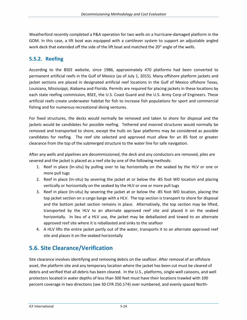
Decommissioning Methodology and Cost Evaluation
ICF International 5-24
Weatherford recently completed a P&A operation for two wells on a hurricane-damaged platform in the
GOM. In this case, a lift boat was equipped with a cantilever system to support an adjustable angled
work deck that extended off the side of the lift boat and matched the 20° angle of the wells.
5.5.2. Reefing
According to the BSEE website, since 1986, approximately 470 platforms had been converted to
permanent artificial reefs in the Gulf of Mexico (as of July 1, 2015). Many offshore platform jackets and
jacket sections are placed in designated artificial reef locations in the Gulf of Mexico offshore Texas,
Louisiana, Mississippi, Alabama and Florida. Permits are required for placing jackets in these locations by
each state reefing commission, BSEE, the U.S. Coast Guard and the U.S. Army Corp of Engineers. These
artificial reefs create underwater habitat for fish to increase fish populations for sport and commercial
fishing and for numerous recreational diving ventures.
For fixed structures, the decks would normally be removed and taken to shore for disposal and the
jackets would be candidates for possible reefing. Tethered and moored structures would normally be
removed and transported to shore, except the hulls on Spar platforms may be considered as possible
candidates for reefing. The reef site selected and approved must allow for an 85 foot or greater
clearance from the top of the submerged structure to the water line for safe navigation.
After any wells and pipelines are decommissioned, the deck and any conductors are removed, piles are
severed and the jacket is placed as a reef site by one of the following methods:
1. Reef in place (In-situ) by pulling over to lay horizontally on the seabed by the HLV or one or
more pull tugs
2. Reef in place (In-situ) by severing the jacket at or below the -85 foot WD location and placing
vertically or horizontally on the seabed by the HLV or one or more pull tugs
3. Reef in place (In-situ) by severing the jacket at or below the -85 foot WD location, placing the
top jacket section on a cargo barge with a HLV. The top section is transport to shore for disposal
and the bottom jacket section remains in place. Alternatively, the top section may be lifted,
transported by the HLV to an alternate approved reef site and placed it on the seabed
horizontally. In lieu of a HLV use, the jacket may be deballasted and towed to an alternate
approved reef site where it is reballasted and sinks to the seafloor
4. A HLV lifts the entire jacket partly out of the water, transports it to an alternate approved reef
site and places it on the seabed horizontally
5.6. Site Clearance/Verification
Site clearance involves identifying and removing debris on the seafloor. After removal of an offshore
asset, the platform site and any temporary location where the jacket has been cut must be cleared of
debris and verified that all debris has been cleared. In the U.S., platforms, single-well caissons, and well
protectors located in water depths of less than 300 feet must have their locations trawled with 100
percent coverage in two directions (see 30 CFR 250.174) over numbered, and evenly spaced North-

Decommissioning Methodology and Cost Evaluation
ICF International 5-25
South and East-West lines on a grid pattern by a trawling contractor who has no corporate or other
financial ties to the company that performed the salvage work. The site is cleared using trawlers
dragging nets across the bottom in a recorded grid pattern of specified coordinates (for a clear grid
pattern) or by the use of other authorized methods using divers or surveys. Any trash that is retrieved
from the sea floor needs to be properly disposed.
When a snag occurs, the exact location is calculated from the navigation data. This snag location and
item is typically buoyed for further identification and removal. Each snag location is recorded and
plotted and described on a final map. Each snag is recovered and the line associated with it is rerun. To
ensure all snags are discovered regardless of the shapes and orientation, all of the even numbered lines
are run in one direction and the odd numbered lines in the opposite direction. If debris is caught in the
nets, it will be removed and stored on deck then transported for proper disposal ashore. A record of the
line number on which it was retrieved is made with a full description of each item. Any sea-life
encountered is returned to the waters.
Regulations require lessees or operators to clear all abandoned well and platform locations of all
obstructions present as a result of oil and gas activities. For exploratory wells drilled with a Mobile
Offshore Drilling Unit (MODU), the site is defined as a 300-foot-radius circle centered on the well. For
single well caissons and well protectors, the site is a 600-foot-radius centered on the well. For platforms,
the area covered by a 1,320-foot-radius circle from the platform’s geometric center must be cleared.
Unless otherwise approved, site clearance and verification must be completed within 60 days after
completing a platform or structure removal or abandonment operation. Trawling grid patterns (see
Figure 5-13) must be as follows for the trawling equipment used:
40-foot grid pattern for vessels trawling with two 50- to 65-foot nets or four 30-foot nets.
60-foot grid pattern for vessels trawling with two 66- to 80-foot nets or four 31- to 40-foot nets.
80-foot grid pattern for vessels trawling with two 81-foot or larger nets or four 41-foot or larger
nets.
Figure 5-13. Site Clearance and VerificationTrawling Patterns

Decommissioning Methodology and Cost Evaluation
ICF International 5-26
An example of trashed collected during site clearance is shown in Figure 5-14.
Figure 5-14 Example Scrap Pile from Site Clearance

Decommissioning Methodology and Cost Evaluation
ICF International 6-1
6. Decommissioning Technologies This section presents additional details on recently developed or improved technologies related to well
P&A, well intervention systems, cutting and severing, heavy lift vessels, and crew transfer technologies.
6.1. Well P&A
6.1.1. Well P&A Spread Deck Layout
Figure 6-1 shows a typical layout of a rigless well P&A equipment spread. Spread size, composition and
weights vary by service provider. Weights (WT) are in pounds.
Figure 6-1. Sample Rigless Equipment Deck Layout
P&A EQUPMENT
LARGE SPREAD
SLICK LINE BOX
WT. 25004' HIGH
89.3 lb/sqft8'
E-LINE BOX
WT. 25004' HIGH
69.4 lb/sqft9'
POWER PACK
WT. 4700
5' HIGH
114 lb/sqft9' - 4'
3'-6
"
100 BBL TANK
WT. 85008' HIGH
78.5 lb/sqft (incl Gas Buster)
21'
DBL DRUM UNIT
WT. 800012' HIGH
W/POWER PACK
138.5 lb/sqft10'-6"
50 BBL BLENDER
WT. 45009' HIGH
lb/sqft
451.6 lb/sqft full 16 ppg
cement
11'
2 BAGS
CEMENT
WT. 4000132.2 lb/sqft
5'-6"
2 BAGS
CEMENT
WT. 4000132.2 lb/sqft
5'-6"
2 BAGS
CEMENT
WT. 4000132.2 lb/sqft
5'-6"
2 BAGS
CEMENT
WT. 4000132.2 lb/sqft
5'-6"
2 BAGS
CEMENT
WT. 4000132.2 lb/sqft
5'-6"
GAS BUSTER
WT. 4500
9' HIGH
4'-6"
4'
8'-5
" 5'-6
"
GARDENER DENVER PUMP
WT. 5000
POWER PACK
WT. 12000
135 lb/sqft
21'
6'
7'-8
"'HOSE BASKET
WT. 5000
4'-8" HIGH202 lb/sqft
5'-6"4'-6
"6
'
LUBRICATOR BOX
WT. 2500
62.5 lb/sqft10'4
'4
'-5"
DOG HOUSE
WT. 80008' HIGH
107.6 lb/sqft
8'-5"'8'-9
"
5'-6
"5
'-6"
5'-6
"5
'-6"
5'-6
"
5M GREASE
SEAL UNIT
WT. 2100140 lb/sqft
OVERBOARD PUMP
WT. 350070.7 lb/sqft
5'-6"'
9'
AIR
COMPRESSOR
WT. 400088.9 lb/sqft
9'
3'
WELLBAY

Decommissioning Methodology and Cost Evaluation
ICF International 6-2
6.1.2. Well P&A Rigless Equipment
Figure 6-2 shows equipment for a typical rigless well P&A spread.
Figure 6-2. Rigless Well P&A Spread
The high pressure pump in Figure 6-3 is used to pump cement and other fluids at up to 15,000 psi and 6
bpm.

Decommissioning Methodology and Cost Evaluation
ICF International 6-3
Figure 6-3. Rigless Well P&A Pump
Figure 6-4 shows a return tank used to capture fluids that are removed from the well bore. The fluids
may include muds, seawater, or hydrocarbons. These are later processed for safe disposal.
Figure 6-4. Rigless P&A Return Tank
A cement blender is used to mix batches of cement for the cement plugs. The cement blender shown in
Figure 6-5 has a capacity of 50 bbls.
Figure 6-5. Well P&A Cement Blender

Decommissioning Methodology and Cost Evaluation
ICF International 6-4
In rigless P&A, wireline units are used in lieu of a drill rig to lower and raise tools, measurement
instruments, or other equipment into and out of a well. The two basic types are slickline, which has a
single strand cable usually less than 1/8” in diameter, and electric line, which has a multi-strand
armored cable that protects an insulated electrical conductor. Double drum units, as shown in Figure
6-6, combine a slickline and an electric line in a single, space-saving unit.
Figure 6-6. Double Drum Wireline Unit
6.1.3. Equipment for Problem Wells
When dealing with problem wells, the following additional equipment may be required for well plugging
and abandonment.
Snubbing Units (Figure 6-7) are used primarily on wells that have sustained casing pressure to force
tubing or casing into the pressurized wellbore. A snubbing unit incorporates a hydraulic jack to exert
upward or downward force on the tubing while slip bowls guard against unwanted movement of the
tubing due to imbalances between the weight of the pipe string and the fluid pressure.

Decommissioning Methodology and Cost Evaluation
ICF International 6-5
Figure 6-7. Snubbing Unit
Hydraulic Workover is a well intervention technique used to install or remove tubular into or out of dead
wells. A “dead well” is a well with zero surface pressure because it has a heavy fluid or mud in the
wellbore or is otherwise not capable of sustaining natural flow. Hydraulic workover can be conducted
for various operations such as well completion, abandonment, fishing and milling operations, and tubing
or casing repair. Figure 6-8 shows a hydraulic workover unit.

Decommissioning Methodology and Cost Evaluation
ICF International 6-6
Figure 6-8. Hydraulic Workover Unit
A Drilling Rig is commonly used for oil and gas drilling operations and can be used for well completion,
production, and abandonment. The main components are draw-works, derrick, mud tank, mud pump,
power source, BOPs, standpipe, pipe rack, drill string/bit, swivel, Kelly drive, and rotary table casing
head or wellhead. Drill rigs for offshore wells can be self-contained mobile floating or jackup units, or
can be permanent rigs installed on an offshore platform.
A Coil Tubing unit (Figure 6-9)is used in the well as a conduit for fishing operations, cleaning up sand
from the tubing, cleaning paraffin buildup in the tubing, or pumping cement in the case of collapsed
tubing or casing. Coil tubing typically varies in size from 1-1/4” to 3-1/2” in diameter.

Decommissioning Methodology and Cost Evaluation
ICF International 6-7
Figure 6-9. Coil Tubing Unit
Milling and Fishing encompass several type of operations, including milling cement plugs from tubing or
casing, milling any kind of downhole obstructions, or section milling a casing window to remediate
sustained casing pressure from annuli. This operation can be performed via coil tubing or a drilling rig.
6.2. Well Intervention Vessels and Systems
Figure 6-10 shows Helix’s Well Ops Q4000 well intervention vessel. This vessel has performed well
intervention work in 6,500 feet in the GOM. The vessel’s ROV is rated to operate at 10,000 feet. The
multipurpose vessel provides a stable platform for a wide variety of tasks, including subsea completion,
decommissioning, and coiled tubing deployment.

Decommissioning Methodology and Cost Evaluation
ICF International 6-8
Figure 6-10. Q4000 Well Intervention Vessel
(Drawing courtesy of Helix Energy)
Another well intervention vessel, the Olympic Intervention IV (Figure 6-11), is chartered to Oceaneering
International, Inc. The vessel is capable of subsea hardware installation such as umbilical’s, subsea trees,
jumpers, flying leads and manifolds. The vessel can also perform inspection, repair and maintenance
(IRM) projects and is capable of well intervention services including riserless wireline, coiled tubing,
electric line, and plug and abandonment operations.

Decommissioning Methodology and Cost Evaluation
ICF International 6-9
Figure 6-11. Oceaneering Well Intervention Vessel (Photo courtesy of Oceaneering)
The AX-S system, developed by the Expro International Group, is a lightweight subsea wireline
intervention system. The AX-S system, deployed from a vessel, can operate in depths up to 10,000 ft and
can significantly reduce subsea intervention time. As a comparison, a typical deep water intervention
can take 12 to 15 days using a rig, compared to eight to 10 days using AX-S (Figure 6-12). The AX-S
System is able to perform well abandonment work on subsea wells.
The AX-S system is deployed onto a subsea tree from a mono hull vessel and is remotely controlled from
the surface like an ROV. It consists of an integrated set of pressure-contained subsea packages
compromising a well control package (WCP), a tool storage package, a wireline winch package, and a
fluid management package. A hydraulic plug-pulling tool overcomes the risks associated with pulling and
setting tree crown plugs. The system has a fully enclosed pressure housing, with no dynamic seals
between the wellbore and surrounding environments. The WCP is a dual safety barrier containing
industry-proven 7 3⁄8-in. shear seal and gate valves. If any safety issues arise, the operator has time to
identify the problem and isolate the wellbore.
The tools are swapped on the seabed in minutes, and because they are held in a pressure-retained
housing, no pressure testing is required after each tool change, saving operations time. The tools are run
in the well by the wireline winch package which is also contained within the pressure housing. The winch
has 25,000 ft (7,620 m) of electric line to convey the intervention tools into the well.
The fluid management package can deploy glycol fluid into the system to flush out seawater and
hydrocarbons that are then circulated back into the well or back to the host subsea production system.
Seawater can also be mixed with the glycol in variable ratios for pressure testing and flushing.

Decommissioning Methodology and Cost Evaluation
ICF International 6-10
Figure 6-12. Expro Group AX-S Subsea Well Intervention System
(Photo courtesy of Expro)
6.3. Cutting and Severing
6.3.1. Explosive Methods
Explosives have been used for cutting and severing in many offshore decommissioning projects. The Gulf
of Mexico has been the worldwide proving ground for platform removals. Explosive severing methods
were used on 67% of platform removals between 1995 and 2005. Figure 6-13 shows a subsea template
that was severed with explosives.
Explosives are widely used to decommission platforms because they are safe, reliable, and cost
effective. The use of explosives reduces the amount of time divers are used during the cutting process,
thereby minimizing human risk. Additionally, the cost of severing piles and conductors is generally less
than 1% of the total platform removal cost. Time is the driving cost factor when discussing severance;
delays in vessel spreads are the primary reason for cost overruns. A failure in the complete severance of
a pile or conductor is usually charged to the owner of the platform. These costs can be enormous, as
time and material rates for large crane vessels can exceed $500,000 dollars per day. The disadvantage of
using explosive is the possible delays and cost associated with marine mammal or turtle sightings.

Decommissioning Methodology and Cost Evaluation
ICF International 6-11
Figure 6-13. Template removal by explosives
(Photo courtesy of Demex International)
The size and weight of a charge can affects the cost of placing the charge, especially in deep water. The
cost for placing charges that weigh under 100 pounds does not significantly change because these
charges are lowered with inexpensive rope. The detonating cord is also a minimal cost component.
Setting a standard Shock Wave Enhancement Device (SWED) device weighing less than 600 pounds only
requires a ¼-inch wire cable. However, the SWED devices are constructed with large-diameter plates in
varying thickness. As plate diameter and thickness increases, costs escalate due to difficulties in
machining and handling the device. Plate diameters over 6 feet are considered special order and
require a long lead-time. Heavier charges required to sever larger piles require larger cable, and
increasing the cable diameter to over 1 inch can have a significant effect on the overall cost.
Many variables can dramatically increase the cost of shaped charges. Nevertheless, of all the uses of
explosives, the shaped charge has developed the most scientific and practical applications. Shaped
charges can be used as precision devices.
6.3.1.1. Explosive Charge Types
Available explosive methods are bulk charges, configured bulk charges, and shaped charges. Remotely
operated vehicles (ROVs), dynamically positioned vessels, wire line units, and detonation of multiple
charges with delays enhance the effectiveness of explosives.

Decommissioning Methodology and Cost Evaluation
ICF International 6-12
Halliburton has developed newer, novel cutting technology and techniques which significantly reduce
the quantity of explosive material required for certain cutting situations, particularly thicker wall tubular
members.
6.3.1.2. Bulk Charges
Bulk charges are a single mass of explosive material detonated at a single point. The energy release from
this type of charge is not well directed. Rather, bulk charges rely on the “brute strength” of the explosive
to overcome the target material by a shattering and tearing effect.
Bulk charges are cylindrical in design as shown in Figure 6-14. These charges vary in length and diameter
to achieve the best fit for a wide range of typical offshore tubulars. Charge diameters range in size from
4” to 12”.
Smaller bulk charges can be arranged to create a larger diameter. This technique allows the technician
to configure the cast explosive material for whatever conditions may arise. For instance, in some cases it
might be advisable to use smaller charges in a circular ring configuration to maximize the explosive
concentration and proximity to the target material. .
Figure 6-14. Bulk Charges
6.3.1.3. Double-Detonation Bulk Charges
The use of a double-detonation bulk charge creates more "cutting power" pound-for-pound than an
ordinary bulk charge. Double detonating the bulk charge is accomplished by using instant non-electric
detonators at opposite ends of the charge. This detonation creates a confluence of energy at the center

Decommissioning Methodology and Cost Evaluation
ICF International 6-13
of the charge, which is dissipated radially outward directly perpendicular into the target material. It is
this directing of explosive energy that makes double-detonating bulk charges more effective.
6.3.1.4. Shock Wave Enhancement/Centralizing Devices
The shock wave enhancement device (SWED) combines the best features of bulk charges with the added
benefit of extreme confinement. A bulk charge is used with a metal and/or concrete plug above the
charge. Centralizers are used to distribute the explosive energy evenly throughout the target area. The
energy released by a bulk charge can be enhanced by the use of tamping or confinement. The addition
of this tamping increases the duration of the impulse that is released by the explosive towards the
target material. Using increased confinement, multiple-point detonation, and the actual water inside of
the tubular to direct energy; this device is the most reliable bulk explosive severance device available to
date.
6.3.1.5. Shaped Charges
The most efficient use of explosives for severing is the shaped charge. The shaped charge uses the
energy produced by the detonation to drive a liner at high velocity at the target. The liner striking the
pipe wall at this accelerated velocity then cuts the target.
Shaped charges have a multitude of manufacturing and design criteria that can drastically affect
performance. The design criterion for shaped charges also requires knowledge of target specifications.
Manufacturing of shaped charges can take many weeks and can cost five times as much as conventional
bulk charges.

Decommissioning Methodology and Cost Evaluation
ICF International 6-14
Figure 6-15. Shaped Charges
Conical, rotationally symmetrical charges (Figure 6-15) produce the greatest penetration of all shaped
charges due to the 360 degrees of radial convergence forming the jet. Variation in the conical liner
angle will result in varying properties of the jet. A small angle will produce a very small, deeply
penetrating jet, while a large angle will produce a larger hole with shallower penetration.
A running linear charge (Figure 6-16) is a roof-shaped liner of a given length used to cut plates or sheets
of metals or other materials. The horizontal velocity of the detonation contributes to its penetrating
effectiveness. It normally comes sheathed in lead in a coil form and can be produced in any desired
length.
A simple cutting charge (or non-running linear charge) has a roof-shaped liner two- to three-times the
liner width. The lower horizontal detonation velocity decreases the cutting effectiveness in this
configuration. This charge has much more explosive above the liner for the increased power required to
cut and to provide a more uniform, flat detonation wave.

Decommissioning Methodology and Cost Evaluation
ICF International 6-15
Figure 6-16. Linear Charge
(Photo courtesy of EBAD)
A planar, symmetric, conical charge is a regular rotationally symmetric shaped charge modified to cut in
a linear fashion by adding massive confinement. The two opposite sides parallel to the central axis have
90 degrees of heavy steel plating affixed to the outside of the charge. This results in uneven collapse of
the liner and a fan shape jet toward the target, producing a slit instead of a round hole.
6.3.1.6. Deep water Issues
Explosives have been used in deep water in a variety of applications. Primarily, the work conducted
relative to offshore structures has been for wells. Conductor wells have been successfully severed in
water depths exceeding 2,850 feet. Explosive charges have been set using divers, remotely operated
vehicles (ROVs), atmospheric diving systems (ADSs), and off the end of drill pipes from drilling vessels
with the aid of underwater cameras.
Pile jetting is necessary in order to place the explosive device inside the pile 20 feet below the mudline.
In deep water this presents a challenge due to hydrostatic pressures encountered during the jetting
operation. Techniques will have to be developed to accomplish this jetting if the jacket is completely
removed. An alternative solution though more expensive would be excavating around the pile to
provide access for severing the pile externally.
6.3.1.7. Effect of Water Depth on Explosives and System Selection
The explosive selected for deep water applications must be one which is not desensitized by water; does
not have components that separate under pressure, and does not become more sensitive with the
expected increase in hydrostatic pressure. This rules out many of the binary explosive mixtures and
blasting gels.

Decommissioning Methodology and Cost Evaluation
ICF International 6-16
It may become necessary to place the detonator underwater. Most common detonators are not
designed for use in water depths over 400 feet; however, seismic detonators can withstand depths of
5,000 feet or more. Factors to consider in detonator selection are:
Metal shell material, diameter, and wall thickness (i.e., will the hydrostatic pressure crush the
detonator?)
Method of sealing around the wires going into the detonator (i.e., will water be forced into the
detonator housing, thereby desensitizing the initiating explosive?).
In the case of non-electric detonators, the housing seal as well as the pressure rating of the shock
tube are factors limiting most non-electric detonators to a maximum of 270 feet.
Only electrical detonators with resistors should be used. With non-resistor electrical detonators,
galvanic current from anodic jacket protection could trigger an unplanned detonation.
There are a number of initiation systems used, depending on the detonator type. These include:
Common electric detonators can be initiated at the surface by almost any electrical means. This
requires connecting two-conductor wires from the detonator to the place of initiation.
Both remote and acoustical firing systems are available for electric detonators. In this type of
initiation system, limiting factors are the distance from the detonator to the receiver and the
distance between the receiver and the transmitter. System costs and deployment methods are
problems with the acoustic system.
Exploding bridge wire (EBW) systems require a firing module and a control unit. The maximum
distance between the firing module and the EBW detonator is 300 feet; the maximum distance
between the firing module and the control unit is 3,000 feet.
Programmable detonators are now available for explosive use.
6.3.1.8. General Cost Estimating Assumptions
Deriving applicable cost matrixes for platform removals using explosives is difficult due to the high
number of variables involved. The following assumptions are generally made in order to properly
analyze when estimating the cost of the use of explosives to sever piles during the removal process:
Government weight restrictions are not a consideration for the explosive charges.
Explosive charge weights are presented in a range, low to high.
The cost of backup charges is not included in this study.
Pipelines in the vicinity are not considered.
National Marine Fisheries Service (NMFS) procedures will be followed.
All government permits will be obtained.
All explosive charges will be set internally to the piles.
For the main piles, the deck will be removed or full access to piles otherwise obtained.
Damaged stabbing guides are not considered.
The explosive charges will not be set inside the stabbing guides.
All piles will be jetted to at least 20’ below the mud line.

Decommissioning Methodology and Cost Evaluation
ICF International 6-17
All piles will be gauged with a “dummy” charge of the same dimensions as the explosive charge.
A crane or some other suitable means will be used to set the explosive charges.
Total explosive charge weights will range between 6,000 and 12,000 pounds, which will require
wire rope diameter to be between ¾ inches to 1-1/8 inches.
Explosive charges will not be left in piles for over 1 week.
Adequate time for manufacturing of charges and mobilization are not considered.
Safety is the number-one priority.
6.3.2. Non-Explosive Methods
Non-explosive methods presently used include diamond wire, guillotine saws, abrasive (slurry) cutters,
mechanical cutters, and oxy-arc torch (diver cutting).
6.3.2.1. Diamond Wire Cutting System
The diamond wire cutting system (DWCS) shown in Figure 6-17 and Figure 6-18 is an external cutting
tool that can be used to cut jacket legs, piles, and diagonal members above and under water. Divers or a
remotely operated vehicle (ROV) can install the DWCS. The DWCS consists of a structural steel clamping
unit and a diamond wire cutter. The frame is designed to clamp on the member being cut. The cutting
wire consists of a steel wire rope with a diameter of approximately ¼-inch onto which is threaded a
series of steel rings approximately ¼-inch long. These rings are embedded with diamonds, and are
separated by a spacer sleeve that places the rings 1-inch apart.
Figure 6-17. Diamond Wire Cutting System
The cutting system is designed to allow the wire to rotate along the perimeter of the frame. The wire
rotates about the pulley wheels. A ROV can be used to set the leg clamp and cutter in the proper

Decommissioning Methodology and Cost Evaluation
ICF International 6-18
position on the member to be cut. Once installed, the DWCS’s wire speed, working pressure, and flow
rate is controlled from the surface.
Diamond wire cutting has been used since the early 1990’s in the North, Adriatic, and Red Seas. Since
then, the DWCS has been used for the removal of offshore platforms, caissons, conductors, risers, etc. It
has been used in the GOM to externally cut 82” and 48” caissons installed in 120 feet of water. Cutting
times were approximately 20 and 2.5 hours for the 82” and 48” caissons respectively.
The DWCS has many possible uses for deep water platform decommissioning. The cutting system can
be used to sever large platform legs and piles while divers sever the diagonal members. An ROV can be
fitted with the cutting tool and sent down to cut the diagonal members at depths where divers cannot
work safely. The same ROV configuration can be used to cut the pipeline ends.
Benefits of this cutting tool over other cutting methods are many. There seems to be no limitation in
the size of the cut or material to cut, as long as the cutting tool can be fixed to the cut member. Water
depth may not be an issue when using this tool; an ROV or diver wearing a hard suit can take and set the
tool at the desired location. By-products generated by the DWCS are only the fine cuttings from the
object being cut, minimizing impacts to the environment.
Limitations of the DWCS are based on its external cutting design. If piles are to be severed below the
mudline, jetting or excavation needs to be performed to allow the cutting device and frame to be
attached to the pile. Additional jetting may be necessary depending on the size of the ROV or other
subsea device being used to attach the unit. An additional limitation of the DWCS is its current control
system.
Developments, currently underway, promise to overcome the limitations in the DWCS's present design.
A sub-bottom cutter (SBC) is currently in development, which will facilitate cuts below the mudline.
Additionally, a computerized cutting control system promises to provide faster cuts that are more
successful in the near future.
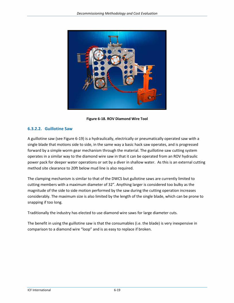
Decommissioning Methodology and Cost Evaluation
ICF International 6-19
Figure 6-18. ROV Diamond Wire Tool
6.3.2.2. Guillotine Saw
A guillotine saw (see Figure 6-19) is a hydraulically, electrically or pneumatically operated saw with a
single blade that motions side to side, in the same way a basic hack saw operates, and is progressed
forward by a simple worm gear mechanism through the material. The guillotine saw cutting system
operates in a similar way to the diamond wire saw in that it can be operated from an ROV hydraulic
power pack for deeper water operations or set by a diver in shallow water. As this is an external cutting
method site clearance to 20ft below mud line is also required.
The clamping mechanism is similar to that of the DWCS but gullotine saws are currently limited to
cutting members with a maximum diameter of 32”. Anything larger is considered too bulky as the
magnitude of the side to side motion performed by the saw during the cutting operation increases
considerably. The maximum size is also limited by the length of the single blade, which can be prone to
snapping if too long.
Traditionally the industry has elected to use diamond wire saws for large diameter cuts.
The benefit in using the guillotine saw is that the consumables (i.e. the blade) is very inexpensive in
comparison to a diamond wire “loop” and is as easy to replace if broken.
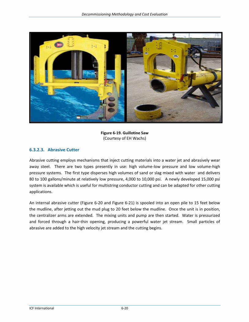
Decommissioning Methodology and Cost Evaluation
ICF International 6-20
Figure 6-19. Guillotine Saw
(Courtesy of EH Wachs)
6.3.2.3. Abrasive Cutter
Abrasive cutting employs mechanisms that inject cutting materials into a water jet and abrasively wear
away steel. There are two types presently in use: high volume-low pressure and low volume-high
pressure systems. The first type disperses high volumes of sand or slag mixed with water and delivers
80 to 100 gallons/minute at relatively low pressure, 4,000 to 10,000 psi. A newly developed 15,000 psi
system is available which is useful for multistring conductor cutting and can be adapted for other cutting
applications.
An internal abrasive cutter (Figure 6-20 and Figure 6-21) is spooled into an open pile to 15 feet below
the mudline, after jetting out the mud plug to 20 feet below the mudline. Once the unit is in position,
the centralizer arms are extended. The mixing units and pump are then started. Water is pressurized
and forced through a hair-thin opening, producing a powerful water jet stream. Small particles of
abrasive are added to the high velocity jet stream and the cutting begins.

Decommissioning Methodology and Cost Evaluation
ICF International 6-21
Figure 6-20. Water abrasive Cutting c/w internal manipulators
Figure 6-21. Water Abrasive Cutting
The external abrasive cutting tool works on the same principle as the internal tool. Using the same
feeding system, the external abrasive cutter is attached using a series of tracks that wrap around the
member to be severed. This system must be attached by a diver, which limits the depth at which this
system can be used safely.
Limitations for both the internal and external abrasive cutters include uneven cutting and water depth
limits. Limitations also include the minimum inside diameter of approximately 7 inches that can be
accessed and the maximum outside diameter that can be cut. In shallow water depths, abrasive cutters
have been proven to be an effective alternative to explosive pile severing. In some circumstances,
conversations with abrasive jet contractors reveal the unsatisfactory use of these cutters in water
depths greater than 600 feet. Improvements to the systems will eventually allow the abrasive cutters to
work in deeper water depths.

Decommissioning Methodology and Cost Evaluation
ICF International 6-22
There also exists the problem of verifying that the cut has been made when using an internal abrasive
cutter. Unlike explosives, the conductor or pile often does not drop, confirming that the cut was
successful. With an abrasive tool, the width of the cut is small and combined with the soil friction, a
visual response generally does not occur. To verify the cut, the conductor is pulled with either the
platform crane or hydraulic jacks. The lift force must overcome the conductor weight and the soil
friction. At times, this force is many times more than the actual conductor weight. It is generally
assumed that the cut is not successful if the conductor cannot be lifted with a force two times the
conductor weight. The abrasive cutting tool is either re-deployed to make another complete run, or
explosives are used to complete the cut.
Recent improvements in abrasive cutting technology have enabled development of a wellhead retrieval
internal multi string cutting tool.
6.3.2.4. Power Shear
Mechanical cuts can be made with hydraulic power shears (Figure 6-22). These mechanical shears use
hydraulic pressure to close metal jaws with enough force to cut through jacket structural members.
Figure 6-22. Hydraulic Mechanical Shear
Above water and underwater cutting technology with remotely controlled self-contained power shears
has seen limited use in the offshore sector. This technology has recently been developed from bridge
pile demolition. This equipment requires a skid mounted power source, cutting unit(s) and one
technician. Cutters have been developed capable of severing up to 48” diameter multi-string conductors
both above and below the waterline.
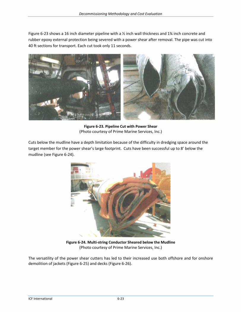
Decommissioning Methodology and Cost Evaluation
ICF International 6-23
Figure 6-23 shows a 16 inch diameter pipeline with a ½ inch wall thickness and 1¾ inch concrete and
rubber epoxy external protection being severed with a power shear after removal. The pipe was cut into
40 ft sections for transport. Each cut took only 11 seconds.
Figure 6-23. Pipeline Cut with Power Shear (Photo courtesy of Prime Marine Services, Inc.)
Cuts below the mudline have a depth limitation because of the difficulty in dredging space around the
target member for the power shear’s large footprint. Cuts have been successful up to 8’ below the
mudline (see Figure 6-24).
Figure 6-24. Multi-string Conductor Sheared below the Mudline
(Photo courtesy of Prime Marine Services, Inc.)
The versatility of the power shear cutters has led to their increased use both offshore and for onshore demolition of jackets (Figure 6-25) and decks (Figure 6-26).

Decommissioning Methodology and Cost Evaluation
ICF International 6-24
Figure 6-25. Power Shear Cutting Platform Jacket
(Photo courtesy of Prime Marine Services, Inc.)
Figure 6-26. Power Shear Cutting Platform Deck Beam
(Photo courtesy of Prime Marine Services, Inc.)
6.3.2.5. Rotary Mechanical Cutter
Rotary mechanical cutting employs hydraulically actuated carbide-tipped tungsten blades to mill
through tubular structures. This method has been used most successfully on small-diameter caissons
with individual wells and shallow water well-protector platforms with vertical piles.
Figure 6-27 illustrates how an internal mechanical cutting tool lowered into an open pile. The power
swivel is supported and connected to the top of the pile. The power swivel turns the drill string so that
the milling blades are forced outward hydraulically to cut the pile or well; centralizers on the tool keep it
concentric inside the pile or well.

Decommissioning Methodology and Cost Evaluation
ICF International 6-25
Limitations for the mechanical cutter include uneven cutting (from lateral movement of uncemented
strings), replacement of worn blades, larger lifting equipment necessary to set the system, and more
time required to make each cut.
Figure 6-27. Mechanical Cutting Tool
6.3.2.6. Carbon Tungsten Beaded Wire Cutter
Versabar has developed a carbon tungsten beaded wire cutting system that can sever 15’ BML. A 2½
inch cutting wire is brought to bear against the member to be cut. Figure 6-28 shows a caisson and
grouted conductors cut and removed with this system.
Figure 6-28. Grouted Caisson Severed with Tungsten Beaded Wire

Decommissioning Methodology and Cost Evaluation
ICF International 6-26
(Photo courtesy of Versabar)
6.3.3. Cutting and Severing Conclusions
Several cutting techniques were reviewed in this section. Explosives are predictable, flexible, and
reliable. Current industry practice primarily utilizes explosives to sever piles below the mudline at any
water depth.
Abrasive and mechanical cutters are not as reliable as explosives to sever piles. Although they have
been proven effective (generally on platforms located in relatively shallow water), deep water
simulation tests have demonstrated that there are a number of operational issues that need to be
resolved for each of these alternative cutting methods. Additionally, there are more delays with these
systems if they fail, and a complete cut during the first pass is less likely to occur than if explosives are
used.
The DWCS is an alternative cutting tool that has great potential for deep water use, specifically for
severing jackets and pipelines. It is relatively easy to install (diver- and ROV-friendly) and current frame
designs fit the pile sizes associated with most platforms. Although the DWCS might soon become a
standard tool for efficiently severing piles, conductors, and pipelines, further testing is necessary before
it can be considered a viable alternative cutting method for deep water platform removals.
While these alternatives may provide a viable alternative to explosive pile severing, potential increases
in cost and diver risk currently make these alternatives less attractive than explosives for the removal of
deep facilities.
6.4. Heavy Lift Technologies
6.4.1. Heavy Lift Vessels
The load weights associated with deep water fixed and floating platform installations limit the number
of heavy lift vessels (HLVs) that have the capacity to remove these facilities. The need for larger HLVs is
apparent as industry is installing more production facilities in deeper waters. Included are brief
descriptions of each of these technologies, and an assessment of the potential to apply them to the
removal of deep water platforms.
A limited selection of heavy lift vessels (HLVs) working around the world today can perform the tasks
required for removing deep water platforms. As of November 2014, there were 107 heavy-lift vessels in
the worldwide fleet with 100 short ton (91 metric ton) capacity or greater, according to Offshore

Decommissioning Methodology and Cost Evaluation
ICF International 6-27
Magazine’s 2014 Worldwide Survey of Heavy Lift Vessels9. Table 6-1 lists the HLVs with lifting
capabilities of 2,000 st or more.
Table 6-1. Heavy Lift Vessels
Largest Crane Vessels
Vessel Company Capacity (mT) Type
Pioneering Spirit Allseas Topside – 48,000; Jacket – 25,000 Twin Hull
TML SeaMetric 20000 Twin vessels
Thialf Heerema 14200 (2 * 7100 tons) Semi
Saipem 7000 Saipem 14000 (2 * 7000 tons) Semi
Bottom Feeder Versabar 10000 Dual Barges
Svanen Ballast Nedam 8800 Catamaran
Hermod Heerema 8165 (1 * 4536, 1 * 3629) Semi
7500 Barge ZPMC 8500 Monohull
Balder Heerema 6350 (1 * 3629, 1 * 2722) Semi
Borealis Nordic 5000 Monohull
Oleg Strashnov Seaway 5000 Monohull
Bottom Feeder Versabar 4000 Twin barges
DB 50 J. Ray 3992 Monohull
Rambiz Scaldis 3300 Catamaran
Asian Hercules II Smit 3200 Monohull
DB 101 J. Ray 3185 Semi
DB 30 J. Ray 2800 Monohull
Sapura 3000 Acergy 2800 Monohull
Stanislav Yudin Seaway 2500 Monohull
Figure 6-29 shows two representative heavy lift vessels.
9 Moon, Ted, “2014 Worldwide Survey of Heavy Lift Vessels”, Offshore Magazine, November, 2014.

Decommissioning Methodology and Cost Evaluation
ICF International 6-28
Figure 6-29. Siapem 7000 and Heerema Thialf Semi-Submersible Crane Vessels
(Photos courtesy of Saimpem and Heerema)
6.4.2. Cargo Barge Capacity
Cargo barge load capacity is limited although Heerema has constructed a large 750 foot long cargo barge
as detailed in the Figure 6-30. Heerema H-851 cargo barge can carry topside modules weighing 35,000
mT or a jacket weighing 40,000 mT.
Figure 6-30. Heerema H-851 Cargo Barge (Drawing courtesy of Heerema)
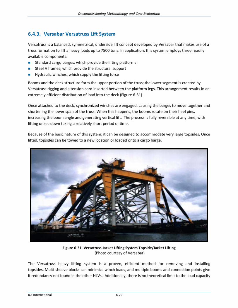
Decommissioning Methodology and Cost Evaluation
ICF International 6-29
6.4.3. Versabar Versatruss Lift System
Versatruss is a balanced, symmetrical, underside lift concept developed by Versabar that makes use of a
truss formation to lift a heavy loads up to 7500 tons. In application, this system employs three readily
available components:
Standard cargo barges, which provide the lifting platforms
Steel A frames, which provide the structural support
Hydraulic winches, which supply the lifting force
Booms and the deck structure form the upper portion of the truss; the lower segment is created by
Versatruss rigging and a tension cord inserted between the platform legs. This arrangement results in an
extremely efficient distribution of load into the deck (Figure 6-31).
Once attached to the deck, synchronized winches are engaged, causing the barges to move together and
shortening the lower span of the truss. When this happens, the booms rotate on their heel pins,
increasing the boom angle and generating vertical lift. The process is fully reversible at any time, with
lifting or set-down taking a relatively short period of time.
Because of the basic nature of this system, it can be designed to accommodate very large topsides. Once
lifted, topsides can be towed to a new location or loaded onto a cargo barge.
Figure 6-31. Versatruss Jacket Lifting System Topside/Jacket Lifting
(Photo courtesy of Versabar)
The Versatruss heavy lifting system is a proven, efficient method for removing and installing
topsides. Multi-sheave blocks can minimize winch loads, and multiple booms and connection points give
it redundancy not found in the other HLVs. Additionally, there is no theoretical limit to the load capacity

Decommissioning Methodology and Cost Evaluation
ICF International 6-30
of this system. However, the Versatruss system is not well suited for removing jackets. The kinematics
of the system make it difficult to provide a jacket lifting capability that would be effective in practical
applications that require lifting jackets out of the water. Therefore, for Complete Removals, another
HLV will be needed. Nevertheless, the Partial Removal and Remote Reefing operations might
significantly benefit from the use of the Versatruss system.
6.4.4. Versabar Bottom Feeder Lift Systems
The Bottom Feeder lift system was developed by Versabar. The design uses two cargo barges outfitted
with a bridge truss that is used to lift jackets and decks Figure 6-32 in a single lift. Consisting of twin
1,250 ton steel truss frames mounted on standard cargo barges and powered by four 200-ton winches
(visible on the legs of the trusses at left), the Bottom Feeder specializes in recovering items from the sea
floor. The retrieved items are loaded onto barges and transported to shore for salvage. The current
system has a rated lift capacity of 4,000 tons and has performed fifty plus salvages related lifts in the
Gulf of Mexico since 2008.
Figure 6-32. Versabar VB 4000 Bottom Feeder Lifting System (Photo courtesy of Versabar)
Deployed for the first time in October 2010, a larger system designated the VB 10,000 is now in full
operation. This unit is rated to handle 10,000 ton surface lifts with four 2,500 ton lift blocks. The blocks
can be re-reeved as required to support sea bed lifting of 4,000 tons. The main block lift height is
approximately 178 feet above sea level. The unit has ABS DPS3 class DP system (Kongsberg control

Decommissioning Methodology and Cost Evaluation
ICF International 6-31
system, eight 1,000 HP Thrustmaster retractable, azimuthing thrusters). The Main hoists are also
capable of each running 10,000 feet of 5-inch Samson Quantam-12 fiber rope. This will give the system a
lifting/lowering capacity of 1,000 tons in 10,000 feet of water.
Figure 6-33. Versabar VB 10,000
(Photo courtesy of Versabar)
The Bottom Feeder has the following advantages:
Single piece lift (removal and installation) of heavy topsides for conventional (non-storm toppled)
platforms.
Heavy jacket removal and installation. The system may transport complete jackets to reef sites for
toppling, or reverse upend jackets for removal to shore. For very large jackets the system can be
used to support and transport jacket slices for disposal.
Use of multiple lift blocks allows for lifting of decks/jackets which are highly out of level (up to 90
degrees) and with highly uncertain CoG or high CoG offset locations.
High lift capacity at (-) 400 feet for continued toppled platform recovery.
High capacity (1,000 tons) for future ultra-deep water (10,000 feet) installations and recoveries.
DP system allows for station keeping in debris fields or deep water.
System has proven to be as or more versatile than conventional derrick barge solutions.
The system’s disadvantages include that the lifting system cannot operate in adverse sea states and the
maximum size of the deck or jacket to be lifted is restricted by the distance between the two barge
hulls.

Decommissioning Methodology and Cost Evaluation
ICF International 6-32
6.4.5. Versabar Claw
In 2011, Versabar deployed a new underwater lift device named “The Claw” to minimize diver exposure
during salvage operations. The Claw can retrieve topsides or damaged platforms from the seafloor with
minimal subsea preparation. Two identical grappling devices measuring 122’ tall, 112’ wide and
weighing 1,000 tons apiece are controlled by the VB 10,000 lift system. Each set of massive steel jaws
operates independently, but for larger loads, can be used in tandem for a double claw lift.
Custom-engineered cradles can be lowered to the seafloor adjacent to sunken platforms to lift fragile
topsides to the surface. Once the Claw scoops up the damaged topside and deposits it on the cradle, the
entire lift package is brought to the surface, placing minimal further stress on the topside.
The Claw has performed a variety of lift operations retrieving various types of structures from 500 ft.
below the surface to an above-water removal of a decommissioned standing platform.
Figure 6-34. Versabar Claw Controlled by VB 10,000 Lift System
(Photo courtesy of Versabar)
6.4.6. Allseas Pioneering Spirit Twin Tanker Lift System
The Allseas Pioneering Spirit (formerly the Pieter Schelte), designed by Excalibur Engineering, BV, is a
twin tanker lift system platform removal and installation vessel formed by joining two large tankers
together to form a stable platform (Figure 6-35). Topsides and jackets can be removed in discrete single
lifts and transported to shore or to another location. Delivery of this vessel is scheduled for first half of
2016.

Decommissioning Methodology and Cost Evaluation
ICF International 6-33
The design of the HLV ties together two large tankers at the stern, leaving the bow open to accept
extremely large topsides. The vessel ballasts itself below the deck, raises (deballasts) to a point where
the jacket can be secured to the vessel, and further deballasts to raise the topsides off the jacket.
The Pioneering Spirit can be used for decommissioning operations by lifting topsides up to 48,000 tons
and removing jackets up to 25,000 tons.
Figure 6-35. Allseas Pioneering Spirit Lifting System Topsides/Jacket
(Drawing courtesy of Allseas)
The Pioneering Spirit heavy lift vessel offers a good alternative to lifting the topsides in one unit. This
also allows much of the cleaning and separation of process facilities to be done onshore. Unlike other
HLV alternatives, the Pioneering Spirit does not have to offload the topsides before lifting the first jacket
section. Additionally, jacket cut sections could be skidded to the back of the vessel, allowing it to lift the
remaining jacket portion to be immediately towed to shallow water to repeat the jacket removal
process.
6.4.7. Buoyancy Bag Devices
Buoyancy bags, manufactured by companies like Seaflex Ltd., are inflatable subsea buoyancy systems
that can be attached to jacket members, subsea equipment, conductors or pipelines. Once attached
and inflated, these units can lift sections (or, in the case of jackets, potentially the entire structure) to
the surface. The bags are offered in either open-bottom or fully enclosed configurations. These units
can be connected to piles or conductors by using divers or remotely operated vehicles (ROVs).
These units have proven to be a successful lifting alternative in pipeline and platform removals. Current
stock exceeds 3,000 ton lift capacity.
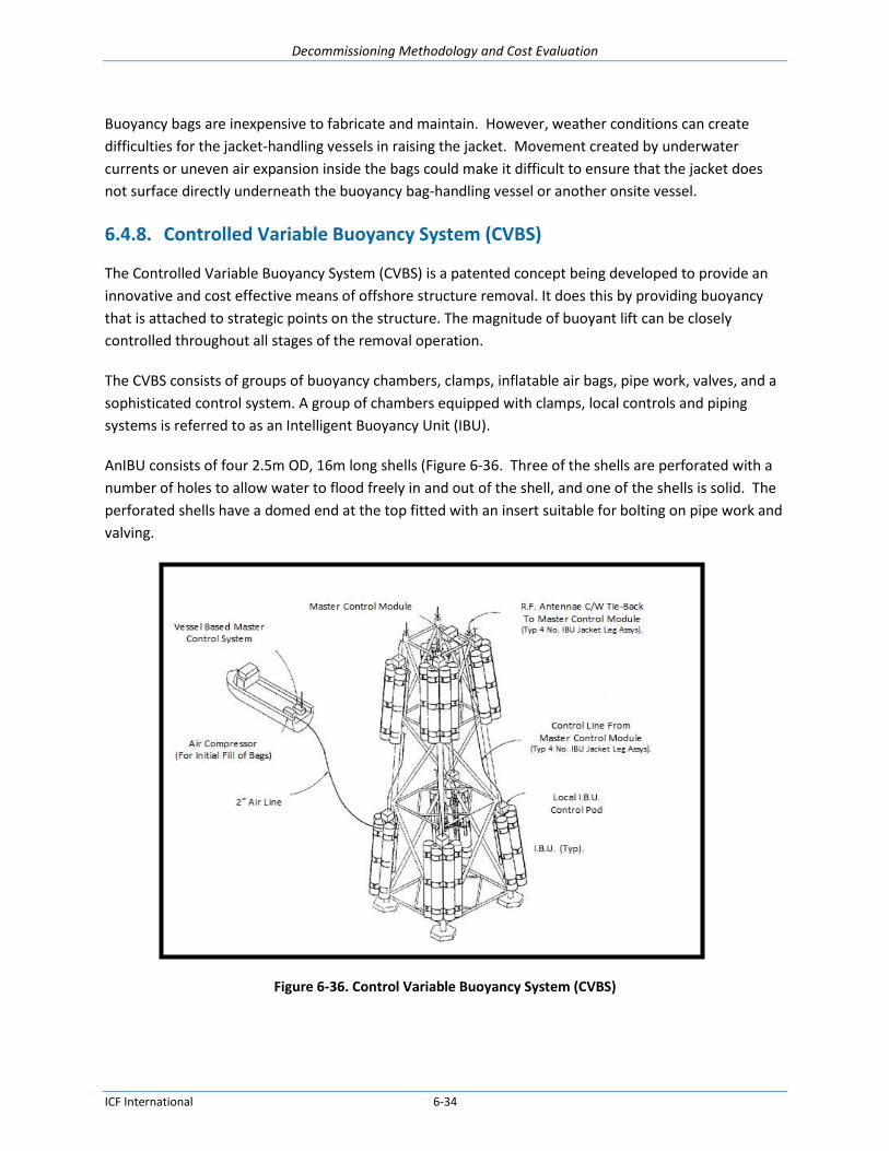
Decommissioning Methodology and Cost Evaluation
ICF International 6-34
Buoyancy bags are inexpensive to fabricate and maintain. However, weather conditions can create
difficulties for the jacket-handling vessels in raising the jacket. Movement created by underwater
currents or uneven air expansion inside the bags could make it difficult to ensure that the jacket does
not surface directly underneath the buoyancy bag-handling vessel or another onsite vessel.
6.4.8. Controlled Variable Buoyancy System (CVBS)
The Controlled Variable Buoyancy System (CVBS) is a patented concept being developed to provide an
innovative and cost effective means of offshore structure removal. It does this by providing buoyancy
that is attached to strategic points on the structure. The magnitude of buoyant lift can be closely
controlled throughout all stages of the removal operation.
The CVBS consists of groups of buoyancy chambers, clamps, inflatable air bags, pipe work, valves, and a
sophisticated control system. A group of chambers equipped with clamps, local controls and piping
systems is referred to as an Intelligent Buoyancy Unit (IBU).
AnIBU consists of four 2.5m OD, 16m long shells (Figure 6-36. Three of the shells are perforated with a
number of holes to allow water to flood freely in and out of the shell, and one of the shells is solid. The
perforated shells have a domed end at the top fitted with an insert suitable for bolting on pipe work and
valving.
Figure 6-36. Control Variable Buoyancy System (CVBS)
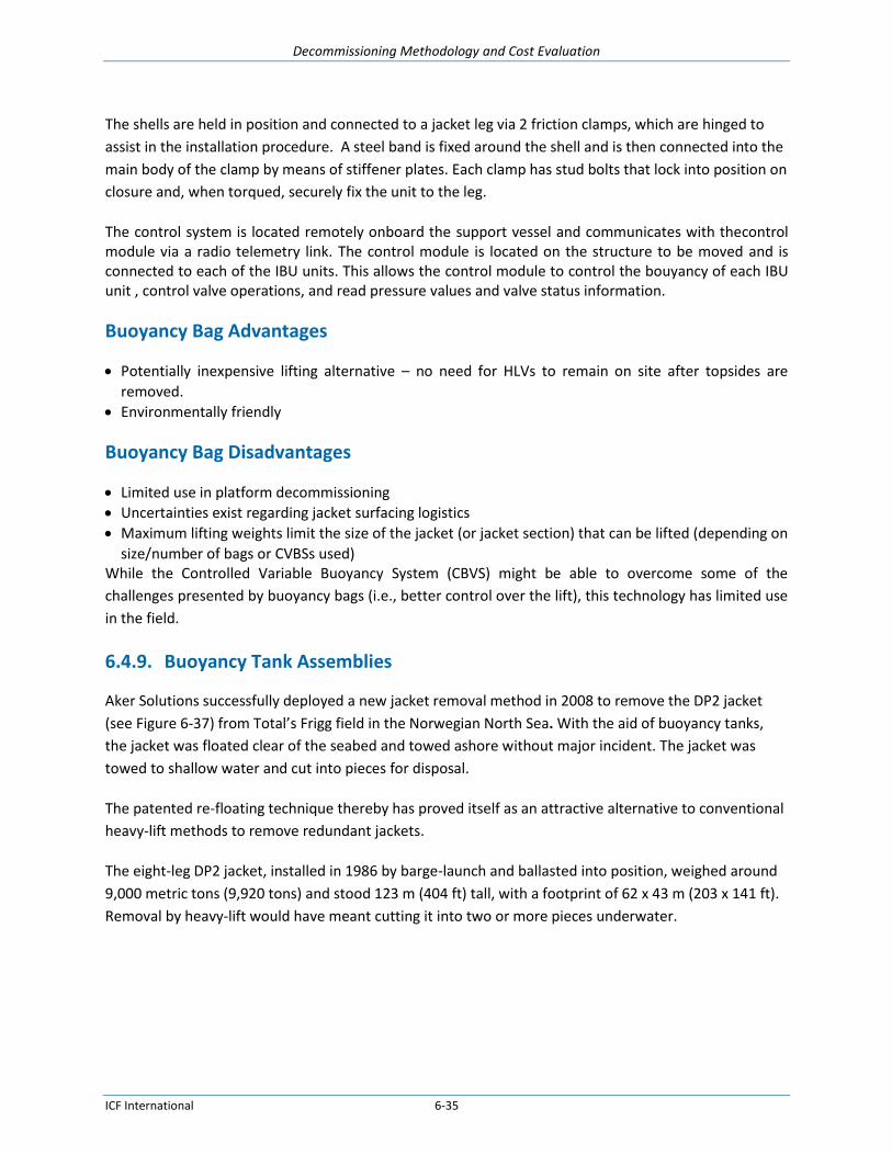
Decommissioning Methodology and Cost Evaluation
ICF International 6-35
The shells are held in position and connected to a jacket leg via 2 friction clamps, which are hinged to
assist in the installation procedure. A steel band is fixed around the shell and is then connected into the
main body of the clamp by means of stiffener plates. Each clamp has stud bolts that lock into position on
closure and, when torqued, securely fix the unit to the leg.
The control system is located remotely onboard the support vessel and communicates with thecontrol module via a radio telemetry link. The control module is located on the structure to be moved and is connected to each of the IBU units. This allows the control module to control the bouyancy of each IBU unit , control valve operations, and read pressure values and valve status information.
Buoyancy Bag Advantages
Potentially inexpensive lifting alternative – no need for HLVs to remain on site after topsides are
removed.
Environmentally friendly
Buoyancy Bag Disadvantages
Limited use in platform decommissioning
Uncertainties exist regarding jacket surfacing logistics
Maximum lifting weights limit the size of the jacket (or jacket section) that can be lifted (depending on
size/number of bags or CVBSs used) While the Controlled Variable Buoyancy System (CBVS) might be able to overcome some of the
challenges presented by buoyancy bags (i.e., better control over the lift), this technology has limited use
in the field.
6.4.9. Buoyancy Tank Assemblies
Aker Solutions successfully deployed a new jacket removal method in 2008 to remove the DP2 jacket
(see Figure 6-37) from Total’s Frigg field in the Norwegian North Sea. With the aid of buoyancy tanks,
the jacket was floated clear of the seabed and towed ashore without major incident. The jacket was
towed to shallow water and cut into pieces for disposal.
The patented re-floating technique thereby has proved itself as an attractive alternative to conventional
heavy-lift methods to remove redundant jackets.
The eight-leg DP2 jacket, installed in 1986 by barge-launch and ballasted into position, weighed around
9,000 metric tons (9,920 tons) and stood 123 m (404 ft) tall, with a footprint of 62 x 43 m (203 x 141 ft).
Removal by heavy-lift would have meant cutting it into two or more pieces underwater.

Decommissioning Methodology and Cost Evaluation
ICF International 6-36
Figure 6-37. Frigg DP2 Platform Removal
This re-floating method uses four buoyancy tank assemblies (BTAs), one attached to each corner leg.
Each BTA consists of two cylindrical buoyancy tanks, each measuring 53 m (184 ft) long and 6.6 m (21.8
ft) in diameter, fixed together side by side. All tanks are divided into an upper and a lower compartment,
with a series of valves allowing sea water entry during ballasting, and pumping in of pressurized air to
expel water during deballasting.
On the upper end is an equipment and instrumentation room for implementing ballasting and de-
ballasting, and for operating the clamps and pull-in jacks that attach the BTA to the jacket leg.
Operations are controlled and powered remotely from a command vessel through an umbilical and
hoses. These were connected directly to the BTA during the attachment operation, and via a manifold
installed on the support vessel during the re-float and tow.
The overall height of each BTA is 65 m (213 ft), the weight in air is about 1,000 metric tons (1,102 tons).
Total tank volume is 3,625 cu m (128,016 cu ft). The units were built and outfitted by Bladt Industrier in
Denmark. The clamp systems and jacks were supplied by IHC, and the rubber elements by Trelleborg
Viking in Norway – the latter were used as fenders and placed within the clamps and upper and lower
guides to deflect loadings.
The mating operation to position a BTA to one of the corner legs without any damage to the integrity of
the jacket was not easy, especially as a positioning accuracy of ±15 mm (0.6-in.) was required, and the
Decommissioning Methodology and Cost Evaluation
ICF International 6-37
weight of each assembly now included 3,000 metric tons (3,308 tons) of ballast water. Each BTA (Figure
6-38) was guided into position using lines attached to a vessel on either side; the offshore support vessel
Botnica, acting as the command vessel, and Nordica. A pull-back line was attached to a small tug
stationed behind the BTA.
Figure 6-38. Buoyancy Tank Assembly
Before re-floating began, the towing vessels attached lines to the jacket to ensure it remained stable. At
this point, the jacket was held in place by just four of the original 20 piles, the others having been
previously cut. With only 600 metric tons (661 tons) of buoyancy from each BTA before the last piles
were cut, the jacket was resting firmly on the already cut piles – enough to hold it stable without causing
any sudden movement when the final pile was severed.
Once the jacket was no longer fixed to the seabed, the BTAs were further de-ballasted to raise the
deepest part of the platform to the towing height of 10 m (33 ft) above the seabed.
The BTAs are available for re-use. With their dimensions, they could re-float jackets weighing between
6,000 and 18,000 metric tons (6,614 and 19,842 tons), depending on the floating capacity in the legs.

Decommissioning Methodology and Cost Evaluation
ICF International 6-38
Further, BTAs with different dimensions and lifting capacities also could be built. BTAs have been
designed to operate in 10,000 feet of water depth.
6.4.10. SeaMetric International TML Lift System
An alternative heavy lift concept has been developed by Seametric International.
SeaMetric’s Twin Marine Lifter (TML) design (see Figure 6-39) is unique. It uses lifting arms rather than
cranes, and will be able to lift 22,000 short tons compared to the maximum lifting capacity of traditional
heavy-left vessels at about 16,000 short tons. Another factor that makes the TML system stand alone is
the removable lifting arms.
Figure 6-39. Seametric International Twin Marine Lifter
(Drawing courtesy of Seametric)
The TML system has DP-3 capability and includes both accommodation facilities and a helideck. It will
operate at wave heights of 10-15 ft with low dynamic loads.
The TML allows design of platform topsides for convenience of operation, not to fit within the crane’s
lifting range. The self-propelled vessel (450 feet long) is designed for both removal and installation of
platform topsides, jackets, subsea installations, boats, or similar objects.
The TML system is based on buoyancy and ballast tanks and lifting arms located on two identical vessels,
each vessel being 459 ft x 131 ft x 35 ft).
The eight lifting arms are supported on a skid structure onboard the vessels. Each lifting arm is hinged to
the skid structure over the center line of the vessel and is equipped with a buoyancy tank on the inside
(between the barge and the object) and a ballast tank on the opposite side.

Decommissioning Methodology and Cost Evaluation
ICF International 6-39
One TML with lifting arms is positioned on each side of the object to be lifted. The system creates a lift
force by de-ballasting the buoyancy tanks while ballasting the ballast tanks. This is done by the use of
seawater pumps.
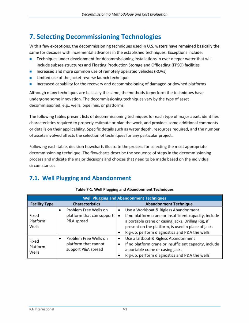
Decommissioning Methodology and Cost Evaluation
ICF International 7-1
7. Selecting Decommissioning Technologies With a few exceptions, the decommissioning techniques used in U.S. waters have remained basically the
same for decades with incremental advances in the established techniques. Exceptions include:
Techniques under development for decommissioning installations in ever deeper water that will
include subsea structures and Floating Production Storage and Offloading (FPSO) facilities
Increased and more common use of remotely operated vehicles (ROVs)
Limited use of the jacket reverse launch technique
Increased capability for the recovery and decommissioning of damaged or downed platforms
Although many techniques are basically the same, the methods to perform the techniques have
undergone some innovation. The decommissioning techniques vary by the type of asset
decommissioned, e.g., wells, pipelines, or platforms.
The following tables present lists of decommissioning techniques for each type of major asset, identifies
characteristics required to properly estimate or plan the work, and provides some additional comments
or details on their applicability. Specific details such as water depth, resources required, and the number
of assets involved affects the selection of techniques for any particular project.
Following each table, decision flowcharts illustrate the process for selecting the most appropriate
decommissioning technique. The flowcharts describe the sequence of steps in the decommissioning
process and indicate the major decisions and choices that need to be made based on the individual
circumstances.
7.1. Well Plugging and Abandonment
Table 7-1. Well Plugging and Abandonment Techniques
Well Plugging and Abandonment Techniques
Facility Type Characteristics Abandonment Technique
Fixed Platform Wells
Problem Free Wells on platform that can support P&A spread
Use a Workboat & Rigless Abandonment
If no platform crane or insufficient capacity, include a portable crane or casing jacks. Drilling Rig, if present on the platform, is used in place of jacks
Rig-up, perform diagnostics and P&A the wells
Fixed Platform Wells
Problem Free Wells on platform that cannot support P&A spread
Use a Liftboat & Rigless Abandonment
If no platform crane or insufficient capacity, include a portable crane or casing jacks
Rig-up, perform diagnostics and P&A the wells

Decommissioning Methodology and Cost Evaluation
ICF International 7-2
Well Plugging and Abandonment Techniques
Facility Type Characteristics Abandonment Technique
Fixed Platform Wells
Problem Wells on platform that can support P&A spread
Use a Workboat & Rigless Abandonment
Depending on well problem, the following spread(s) would be included o Snubbing Unit o Coil Tubing Unit o Hydraulic Workover Unit o Drilling Rig o Milling Tools
If no platform crane or insufficient capacity, include a portable crane or casing jacks. Drilling Rig, if present on the platform, is used in place of jacks
Rig-up, perform diagnostics and P&A the wells
Fixed Platform Wells
Problem Wells on platform that cannot support P&A spread
Use a Liftboat & Rigless Abandonment
Depending on well problem, the following spread(s) would be included o Snubbing Unit o Coil Tubing Unit o Hydraulic Workover Unit o Drilling Rig o Milling Tools
If no platform crane or insufficient capacity, include a portable crane or casing jacks. Drilling Rig, if present on the platform, is used in place of jacks
Rig-up, perform diagnostics and P&A the wells
Floating Platform Dry Tree Wells
Problem Free Wells Use a Workboat, Rigless Abandonment and casing jacks. Drilling Rig, if present on the platform, is used in place of jacks
Rig-up, perform diagnostics and P&A the wells
Floating Platform Dry Tree Wells
Problem Wells Use a Workboat, Rigless Abandonment and casing jacks. Drilling Rig, if present on the platform, is used in place of jacks
Depending on well problem, the following spread(s) would be included o Snubbing Unit o Coil Tubing Unit o Hydraulic Workover Unit o Drilling Rig o Milling Tools
Rig-up, perform diagnostics and P&A the wells

Decommissioning Methodology and Cost Evaluation
ICF International 7-3
Well Plugging and Abandonment Techniques
Facility Type Characteristics Abandonment Technique
Subsea Wells
Water Depth <800m?
Non Problem Well or Problem Well?
Divers or ROV?
Can well be plugged using rigless methods?
Selection of work and vessel spreads depends on condition of well and water depth o Rig-up, perform diagnostics and P&A the wells o Complete Removal 15’ bellow mud line. o Remove Tree and wellhead, unless waiver to
leave wellhead is obtained
Subsea Wells
Water Depth >800m
Non Problem Well or Problem Well
Divers and or ROV
Can well be plugged using rigless methods?
Selection of work and vessel spreads depends on condition of well and water depth o Rig-up, perform diagnostics and P&A the wells o Remove Tree, obtain waiver to leave wellhead
7.2. Pipeline Decommissioning
Table 7-2. Pipeline Abandonment Techniques
Pipeline Abandonment Techniques
Facility Type Characteristics Abandonment Technique
Riser to Riser Riser to SSTI SSTI to SSTI
Diameter, length, product
Flushed fluids can or cannot be pumped down hole, through the pipeline or filtering equipment is or is not present on the receiving end
Selection of work and vessel spreads depends on type of pipeline, whether fluids are flushed, depth of cover over the pipeline, and water depth o Flushed clean, cut ends, remove a section from
each end, plug and bury o Flush clean and remove pipeline in sections o Flush clean and remove pipeline by reverse
reeling
7.3. Umbilical Decommissioning
Table 7-3. Umbilical Decommissioning Techniques
Umbilical Decommissioning Techniques
Facility Type Characteristics Abandonment Technique
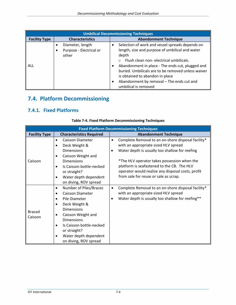
Decommissioning Methodology and Cost Evaluation
ICF International 7-4
Umbilical Decommissioning Techniques
Facility Type Characteristics Abandonment Technique
ALL
Diameter, length
Purpose - Electrical or other
Selection of work and vessel spreads depends on length, size and purpose of umbilical and water depth o Flush clean non- electrical umbilicals.
Abandonment in place - The ends cut, plugged and buried. Umbilicals are to be removed unless waiver is obtained to abandon in place
Abandonment by removal – The ends cut and umbilical is removed
7.4. Platform Decommissioning
7.4.1. Fixed Platforms
Table 7-4. Fixed Platform Decommissioning Techniques
Fixed Platform Decommissioning Techniques
Facility Type Characteristics Required Abandonment Technique
Caisson
Caisson Diameter
Deck Weight & Dimensions
Caisson Weight and Dimensions
Is Caisson bottle-necked or straight?
Water depth dependent on diving, ROV spread
Complete Removal to an on-shore disposal facility* with an appropriate sized HLV spread
Water depth is usually too shallow for reefing *The HLV operator takes possession when the platform is seafastened to the CB. The HLV operator would realize any disposal costs, profit from sale for reuse or sale as scrap.
Braced Caisson
Number of Piles/Braces
Caisson Diameter
Pile Diameter
Deck Weight & Dimensions
Caisson Weight and Dimensions
Is Caisson bottle-necked or straight?
Water depth dependent on diving, ROV spread
Complete Removal to an on-shore disposal facility* with an appropriate sized HLV spread
Water depth is usually too shallow for reefing**

Decommissioning Methodology and Cost Evaluation
ICF International 7-5
Fixed Platform Decommissioning Techniques
Facility Type Characteristics Required Abandonment Technique
Platforms (3 Pile and Greater)
Number of Piles if different from legs
Pile Diameter
Deck Weight & Dimensions
Jacket Weight and Dimensions
Water depth dependent on diving, ROV spread
Complete Removal to an on-shore disposal facility* as a single lift, in multiple lifts in-situ, or hopping off site, with all material removed to shore
Remove top 85’ section to shore disposal facility* and reef remainder in place
Reef top 85’ section next to lower section in place
In-Situ (Topple as a reef)
Remove to a remote Reef Site intact or in pieces
Compliant Tower (without guy lines)
Number of Piles if different from legs
Pile Diameter
Deck Weight & Dimensions
Jacket Weight and Dimensions
Buoyancy tank details
Water depth dependent on diving, ROV spread
Complete Removal in multiple lifts in-situ or by re-floating and moving to shallow water for sectioning, with all material removed to shore disposal facility*
Remove top 85’ section to shore and reef remainder in place
Reef in situ with top 85’ section next to lower section in place
In-Situ (Topple as a reef)
Re-float, remove to a remote Reef Site intact and sink or place on the seabed
Compliant Tower (with guy lines)
Number of Piles if different from legs
Pile Diameter
Deck Weight & Dimensions
Jacket Weight and Dimensions
Buoyancy tank details
Guy line details
Water depth dependent on diving, ROV spread
Complete Removal by re-floating and moving to shallow water for sectioning, with all material removed to shore
In-Situ (Topple as a reef)
Re-float, remove to a remote Reef Site intact and sink or place on the seabed
7.4.2. Floating Platforms
Table 7-5. Floating Platform Decommissioning Techniques
Floating Platform Decommissioning Techniques
Facility Type Characteristics Required Abandonment Technique
FPSO
Hull Weight and Dimensions
Weight and Dimensions of Equipment
Mooring System Details
Water Depth
Complete Removal to an on-shore disposal facility

Decommissioning Methodology and Cost Evaluation
ICF International 7-6
Floating Platform Decommissioning Techniques
Facility Type Characteristics Required Abandonment Technique
MTLP / TLP
Hull Weight and Dimensions
Deck Weight and Dimensions
Equipment Weight and Dimensions
Mooring System Details
Water Depth
Complete Removal to an on-shore disposal facility
Remove deck to shore and hull to shallow water for reefing
Semi-submersible
Hull Weight and Dimensions
Deck Weight and Dimensions
Equipment Weight and Dimensions
Mooring System Details
Water Depth
Complete Removal to an on-shore disposal facility
Remove deck to shore and hull to shallow water for reefing
Spar
Hull Weight and Dimensions
Deck Weight and Dimensions
Equipment Weight and Dimensions
Mooring System Details
Water Depth
Complete Removal to an on-shore disposal facility
Remove deck to shore and hull to shallow water for reefing
7.5. Subsea Structure Decommissioning
Table 7-6. Subsea Structure Decommissioning Techniques
Subsea Structure Decommissioning Techniques
Facility Type Characteristics Required Abandonment Technique
Manifolds Lift weights & dimensions
Water Depth
Complete Removal
Abandon in-place
PLET Lift weights & dimensions
Water Depth
Complete Removal
Abandon in-place
Jumper Lift weights & dimensions
Water Depth
Complete Removal
Abandon in-place
Wellhead and Subsea Tree
Lift weights & dimensions
Water Depth
Complete Removal
Abandon in-place
SUTA Lift weights & dimensions
Water Depth
Complete Removal
Abandon in-place

Decommissioning Methodology and Cost Evaluation
ICF International 7-7
7.6. Decision Flowcharts
Decision flowcharts illustrate the process for selecting the most appropriate decommissioning
technique. The flowcharts describe the sequence of steps in the decommissioning process and indicate
the major decisions and choices that need to be made based on the individual circumstances.
Flowcharts are presented for
Well Plugging and Abandonment, Platform Wells (Dry Tree)
Well Plugging and Abandonment, Subsea Wells (Wet Tree)
Pipeline Decommissioning, Riser to Riser
Pipeline Decommissioning, Riser to SSTI
Pipeline Decommissioning, SSTI to SSTI
Umbilical Decommissioning
Platform Decommissioning, Fixed Platforms, Caisson
Platform Decommissioning, Fixed Platforms, Caisson, Single Lift
Platform Decommissioning, Fixed Platforms, Braced Caisson
Platform Decommissioning, Fixed Platforms, Steel Jacket, Complete Removal
Platform Decommissioning, Fixed Platforms, Steel Jacket, Artificial Reef
Platform Decommissioning, Floating Platforms
Subsea Structure Decommissioning

Decommissioning Methodology and Cost Evaluation
ICF International 7-8
7.6.1. Well Plugging and Abandonment
7.6.1.1. Platform Wells (Dry Tree)

Decommissioning Methodology and Cost Evaluation
ICF International 7-9
7.6.1.2. Subsea Wells (Wet Tree)
Following Information Service provider needs to know
Field Location
Water Depth (WD)
Number of wells to P&A/T&A
Hours of operations:
12 Hrs. - 5 man crew & supervisor (Generalized as each provider is different)
24 Hrs. - 10 man crew & 1 or 2 Supervisors
Wellbore characteristics and history
Well Equipment weight & dimension (Equipment Load out Sheet)
Any known well problems will dictate extra equipment, personnel, duration
What is the maximum well weight to pull (tubulars, casings, etc.)
DIVING TABLE
WD <120' – Surface Air Divers
WD 121'-299' – Mixed Gas Divers
WD 300’-800’ – Saturation Divers
WD > 800’ – ROV only
Diving depths are generalized
Subsea Well Abandonment
Water
Depth
Problem Well
Same as for problem free well except additional equipment and personnel would
be included in the spread depending on the well problem
Coil Tubing Unit
Drilling Rig
Milling Tools
If the incorrect resources are on site an unable to complete the well P&A, the
well could be TA (Temporary Abandoned) until the needed resources are
mobilized.
Wet Tree
(Subsea)
*Waiver can be
obtained to leave the
wellhead & Stubs at
800 M (2625 Ft) deep
or other approved WD
What Type of
Well
Shallow water subsea
wells require wellhead
& stubs removal @ +
15’ BML
Problem Free
WELL INTERVENTION VESSEL TABLE
WD <299' – Jack-up Rig, Moored Semi-Sub Rig,
Semi-sub DP, Drillship, MSV, MSV-T
WD 300' – 2,000’ – Moored Semi-Sub Rig,
Semi-sub DP, Drillship, MSV-T
WD > 2,001’ – Semi-sub DP, Drillship, MSV, MSV-T
Limitation is equipment depth capability
WD 121'-299'
Dive Spread 2
Mobilize to well w/
DP DSV, Subsea
Well P&A Vessel
(Jack-up/Moored
Semi-sub/Demi-sub
DP/
Drillship/MSV/MSV-
T) & Equipment,
consumables &
appropriate divers
from dive spread
table
P&A the well,
severing and
removing the
conductor 15’ BML
Demobilize
WD 300'-800’
Dive Spread 3
Mobilize to well w/
DP DSV, Subsea
Well P&A Vessel
(Moored Semi-
sub/Semi-sub
DP/Drillship/MSV-
T), Well P&A Crew
& Equipment,
consumables &
appropriate divers
from dive spread
table
P&A the well,
severing and
removing the
conductor 15’ BML
Demobilize
Dive Spread 1
Mobilize to well w/
4-Point Diveboat,
Subsea Well P&A
Vessel (Jack-
up/Moored Semi-
sub/Demi-sub DP/
Drillship/MSV/MSV
-T), Well P&A Crew
& Equipment,
consumables &
appropriate divers
from dive spread
table
P&A the well,
severing and
removing the
conductor 15’ BML
Demobilize
WD <120' WD 801'-2,000’
Dive Spread 4
Mobilize to w/
Subsea Well P&A
(Moored Semi-
sub/Semi-sub
DP/Drillship/MSV-
T), Well P&A Crew &
Equipment,
consumables &
appropriate divers
from dive spread
table
P&A the well,
severing and
removing the
conductor 15’
BML*
Demobilize
WD 2,001'-2,625’
Dive Spread 4
Mobilize to w/
Subsea Well P&A
(Moored Semi-
sub/Semi-sub
DP/Drillship/MSV-
T), Well P&A Crew &
Equipment,
consumables &
appropriate divers
from dive spread
table
P&A the well,
severing and
removing the
conductor 15’
BML*
Demobilize
WD > 2,626'
Dive Spread 4
Mobilize to w/
Subsea Well P&A
(Moored Semi-
sub/Semi-sub
DP/Drillship/MSV-
T), Well P&A Crew &
Equipment,
consumables &
appropriate divers
from dive spread
table
P&A the well,
Abandon wellhead
& tree in place
Demobilize

Decommissioning Methodology and Cost Evaluation
ICF International 7-10
7.6.2. Pipeline Decommissioning
7.6.2.1. Riser to Riser
Spread 1a
Rig-up &
Flush pipeline,
Rig-down, Cut
and remove tube
turn, Plug and
bury pipeline end
Spread 1b
Process incoming
fluids, removing
hydrocarbons,
Demobilize
Spread 1a
Relocate to
opposite end,
Cut and remove
tube turn,
Plug and bury
pipeline end,
Demobilize
Spread 2a
Rig-up &
Flush pipeline,
Rig-down, Cut
and remove tube
turn, Plug and
bury pipeline end
Spread 2b
Process incoming
fluids, removing
hydrocarbons &
capturing them in
tanks, Demobilize
Spread 3a
Rig-up &
Flush pipeline,
Rig-down, Cut
and remove tube
turn, Plug and
bury pipeline end
Spread 3b
Process incoming
fluids, removing
hydrocarbons,
Demobilize
Spread 4a
Rig-up & Flush
pipeline, Rig-
down, Cut and
remove tube turn,
Plug and bury
pipeline end
Spread 4b
Process incoming
fluids, removing
hydrocarbons &
capturing them in
tanks, Demobilize
Spread 5a
Rig-up &
Flush pipeline,
Rig-down, Cut
and remove tube
turn, Plug and
bury pipeline end
Spread 5b
Process incoming
fluids, removing
hydrocarbons,
Demobilize
Spread 6a
Rig-up &
Flush pipeline,
Rig-down, Cut
and remove tube
turn, Plug and
bury pipeline end
Spread 6b
Process incoming
fluids, removing
hydrocarbons &
capturing them in
tanks, Demobilize
Spread 7a
Rig-up &
Flush pipeline,
Rig-down, Cut
and remove tube
turn, Plug and
bury pipeline end
Spread 7b
Process incoming
fluids, removing
hydrocarbons,
Demobilize
Spread 8a
Rig-up &
Flush pipeline,
Rig-down, Cut
and remove tube
turn, Plug and
bury pipeline end
Spread 8b
Process incoming
fluids, removing
hydrocarbons &
capturing them in
tanks, Demobilize
Spread 2a
Relocate to
opposite end,
Cut and remove
tube turn,
Plug and bury
pipeline end,
Demobilize
Spread 3a
Relocate to
opposite end,
Cut and remove
tube turn,
Plug and bury
pipeline end,
Demobilize
Spread 4a
Relocate to
opposite end,
Cut and remove
tube turn,
Plug and bury
pipeline end,
Demobilize
Spread 5a
Relocate to
opposite end,
Cut and remove
tube turn,
Plug and bury
pipeline end,
Demobilize, and
Saturation
Decompression
Spread 6a
Relocate to
opposite end,
Cut and remove
tube turn,
Plug and bury
pipeline end,
Demobilize, and
Saturation
Decompression
Spread 7a
Relocate to
opposite end,
Cut and remove
tube turn,
Plug and bury
pipeline end,
Demobilize
Spread 8a
Relocate to
opposite end,
Cut and remove
tube turn,
Plug and bury
pipeline end,
Demobilize

Decommissioning Methodology and Cost Evaluation
ICF International 7-11
7.6.2.2. Riser to SSTI
Water Depth (WD) at origination Water Depth at destination Maximum (Max) WD is the greater of the two Size OD (in.) Length (ft.) Product Status code
Pipeline Abandonment
End termination
location and type
YES NO
What is the
Max WD*
WD <120' WD 121'-299'
WD 300'-800’
WD >800'
* Some overlapping of water depths and diving resources can occur. Water depth/resources here are generalized.
YES NO YES NO
YES NO
Spread 1a
Mobilize to
originating
platform w/
Workboat,
Flushing Crew &
Equipment
Spread 1b
Mobilize to SSTI
w/ 4-Point DSV,
Surface Air Divers
Are you
able to
pump into
the SSTI
Are you
able to
pump into
the SSTI
Are you
able to
pump into
the SSTI
Are you
able to
pump into
the SSTI
Spread 2a
Mobilize to SSTI
w/ 4-Point DSV,
Surface Air
Divers, Flushing
Crew &
Equipment
Spread 2b
Mobilize to
originating
platform w/
Workboat,
Filtration Crew &
Equipment and
Hydrocarbon
capture tanks
Spread 3a
Mobilize to
originating
platform w/
Workboat,
Flushing Crew &
Equipment
Spread 3b
Mobilize to SSTI
w/ 4-Point DSV,
Mixed Gas Divers
Spread 4a
Mobilize to SSTI
w/ 4-Point DSV,
Mixed Gas Divers,
Flushing Crew &
Equipment
Spread 4b
Mobilize to
originating
platform w/
Workboat,
Filtration Crew &
Equipment and
Hydrocarbon
capture tanks
Spread 5a
Mobilize to
originating
platform w/
Workboat,
Flushing Crew &
Equipment
Spread 5b
Mobilize to SSTI
w/ DP DSV,
Saturation Divers
Spread 6a
Mobilize to SSTI
w/ DP DSV,
Saturation Divers,
Flushing Crew &
Equipment
(Coil Tubing is
required for water
depths >600’)
Spread 6b
Mobilize to
originating
platform w/
Workboat,
Filtration Crew &
Equipment and
Hydrocarbon
capture tanks
Spread 7a
Mobilize to
originating
platform w/
Workboat,
Flushing Crew &
Equipment
Spread 7b
Mobilize to SSTI
w/ DP DSV, Dual
ROV system
Spread 8a
Mobilize to SSTI
w/ DP DSV, Dual
ROV system,
Flushing Crew &
Equipment, and
Coil Tubing
Spread 8b
Mobilize to
originating
platform w/
Workboat,
Filtration Crew &
Equipment and
Hydrocarbon
capture tanks
Riser to SSTI
Spread 1a
Rig-up &
Flush pipeline
into SSTI,
Rig-down,
Demobilize
Spread 1b
Cut and remove
5’ section at SSTI,
Plug and bury
pipeline end
Spread 1b
Relocate to
platform end, Cut
and remove tube
turn, Plug and
bury pipeline end,
Demobilize
Spread 2a
Rig-up &
Flush pipeline
from SSTI,
Rig-down, Cut
and remove 5’
section at SSTI,
Plug and bury
pipeline end
Spread 2b
Process incoming
fluids, removing
hydrocarbons &
capturing them in
tanks, Demobilize
Spread 3a
Rig-up &
Flush pipeline
into SSTI,
Rig-down,
Demobilize
Spread 3b
Cut and remove
5’ section at SSTI,
Plug and bury
pipeline end
Spread 4a
Rig-up &
Flush pipeline
from SSTI,
Rig-down, Cut
and remove 5’
section at SSTI,
Plug and bury
pipeline end
Spread 4b
Process incoming
fluids, removing
hydrocarbons &
capturing them in
tanks, Demobilize
Spread 5a
Rig-up &
Flush pipeline
into SSTI,
Rig-down,
Demobilize
Spread 5b
Cut and remove
5’ section at SSTI,
Plug and bury
pipeline end
Spread 6a
Rig-up &
Flush pipeline
from SSTI,
Rig-down, Cut
and remove 5’
section at SSTI,
Plug and bury
pipeline end
Spread 6b
Process incoming
fluids, removing
hydrocarbons &
capturing them in
tanks, Demobilize
Spread 7a
Rig-up &
Flush pipeline
into SSTI,
Rig-down,
Demobilize
Spread 7b
Cut and remove
5’ section at SSTI,
Plug and bury
pipeline end
Spread 8a
Rig-up &
Flush pipeline
from SSTI,
Rig-down, Cut
and remove 5’
section at SSTI,
Plug and bury
pipeline end
Spread 8b
Process incoming
fluids, removing
hydrocarbons &
capturing them in
tanks, Demobilize
Spread 2a
Relocate to
platform end, Cut
and remove tube
turn, Plug and
bury pipeline end,
Demobilize
Spread 3b
Relocate to
platform end, Cut
and remove tube
turn, Plug and
bury pipeline end,
Demobilize
Spread 4a
Relocate to
platform end, Cut
and remove tube
turn, Plug and
bury pipeline end,
Demobilize
Spread 5b
Relocate to
platform end, Cut
and remove tube
turn, Plug and
bury pipeline end,
Demobilize, and
Saturation
Decompression
Spread 6a
Relocate to
platform end, Cut
and remove tube
turn, Plug and
bury pipeline end,
Demobilize, and
Saturation
Decompression
Spread 7b
Relocate to
platform end, Cut
and remove tube
turn, Plug and
bury pipeline end,
Demobilize
Spread 8a
Relocate to
platform end, Cut
and remove tube
turn, Plug and
bury pipeline end,
Demobilize

Decommissioning Methodology and Cost Evaluation
ICF International 7-12
7.6.2.3. SSTI to SSTI
Water Depth (WD) at origination Water Depth at destination Maximum (Max) WD is the greater of the two Size OD (in.) Length (ft.) Product Status code
Pipeline Abandonment
End termination
location and type
YES NO
What is the
Max WD*
WD <120' WD 121'-299'
WD 300'-800’
WD >800'
* Some overlapping of water depths and diving resources can occur. Water depth/resources here are generalized.
YES NO YES NO
YES NO
Spread 1a
Mobilize to
originating SSTI
w/ 4-Point DSV,
Surface Air
Divers,
Flushing Crew &
Equipment
Spread 1b
Mobilize to SSTI
w/ 4-Point DSV,
Surface Air Divers
Are you
able to
pump into
the SSTI
Are you
able to
pump into
the SSTI
Are you
able to
pump into
the SSTI
Are you
able to
pump into
the SSTI
Spread 2a
Mobilize to
originating SSTI
w/ 4-Point DSV,
Surface Air
Divers, Flushing
Crew &
Equipment
Spread 2b
Mobilize to SSTI
w/ 4-Point DSV,
Surface Air
Divers, Filtration
Crew &
Equipment and
Hydrocarbon
capture tanks
Spread 3a
Mobilize to
originating SSTI
w/ 4-Point DSV,
Mixed Gas Divers,
Flushing Crew &
Equipment
Spread 3b
Mobilize to SSTI
w/ 4-Point DSV,
Mixed Gas Divers
Spread 4a
Mobilize to
originating SSTI
w/ 4-Point DSV,
Mixed Gas Divers,
Flushing Crew &
Equipment
Spread 4b
Mobilize to SSTI
w/ 4-Point DSV,
Mixed Gas Divers,
Filtration Crew &
Equipment and
Hydrocarbon
capture tanks
Spread 5a
Mobilize to
originating SSTI
w/ DP DSV,
Saturation Divers,
Flushing Crew &
Equipment
(Coil Tubing is
required for water
depths >600’)
Spread 5b
Mobilize to SSTI
w/ DP DSV,
Saturation Divers
Spread 6a
Mobilize to
originating SSTI
w/ DP DSV,
Saturation Divers,
Flushing Crew &
Equipment
(Coil Tubing is
required for water
depths >600’)
Spread 6b
Mobilize to SSTI
w/ 4-Point DSV,
Saturation Divers,
Filtration Crew &
Equipment and
Hydrocarbon
capture tanks
Spread 7a
Mobilize to
originating SSTI
w/ DP DSV, Dual
ROV system,
Flushing Crew &
Equipment, and
Coil Tubing
Spread 7b
Mobilize to SSTI
platform w/
DP DSV, Dual
ROV system
Spread 8a
Mobilize to
originating SSTI
w/ DP DSV, Dual
ROV system,
Flushing Crew &
Equipment, and
Coil Tubing
Spread 8b
Mobilize to SSTI
w/ DP DSV, Dual
ROV system,
Filtration Crew &
Equipment and
Hydrocarbon
capture tanks
SSTI to SSTI
Spread 1a
Rig-up &
Flush pipeline
into SSTI,
Rig-down,
Demobilize
Spread 1b
Cut and remove
5’ section at SSTI,
Plug and bury
pipeline end
Spread 1b
Relocate to
originating end,
Cut and remove
5’ section at SSTI,
Plug and bury
pipeline end,
Demobilize
Spread 2a
Rig-up &
Flush pipeline
from SSTI,
Rig-down,
Demobilize
Spread 2b
Process incoming
fluids, removing
hydrocarbons &
capturing them in
tanks, cut and
remove 5’ section
at SSTI, Plug and
bury pipeline end
Spread 3a
Rig-up &
Flush pipeline
into SSTI,
Rig-down,
Demobilize
Spread 3b
Cut and remove
5’ section at SSTI,
Plug and bury
pipeline end
Spread 4a
Rig-up &
Flush pipeline
from SSTI,
Rig-down,
Demobilize
Spread 4b
Process incoming
fluids, removing
hydrocarbons &
capturing them in
tanks, cut and
remove 5’ section
at SSTI, Plug and
bury pipeline end
Spread 5a
Rig-up &
Flush pipeline
into SSTI,
Rig-down,
Demobilize
Spread 5b
Cut and remove
5’ section at SSTI,
Plug and bury
pipeline end
Spread 6a
Rig-up &
Flush pipeline
from SSTI,
Rig-down,
Demobilize
Spread 6b
Process incoming
fluids, removing
hydrocarbons &
capturing them in
tanks, cut and
remove 5’ section
at SSTI, Plug and
bury pipeline end
Spread 7a
Rig-up &
Flush pipeline
from SSTI,
Rig-down,
Demobilize
Spread 7b
Cut and remove
5’ section at SSTI,
Plug and bury
pipeline end
Spread 8a
Rig-up &
Flush pipeline
from SSTI,
Rig-down,
Demobilize
Spread 8b
Process incoming
fluids, removing
hydrocarbons &
capturing them in
tanks, cut and
remove 5’ section
at SSTI, Plug and
bury pipeline end
Spread 2a
Relocate to
originating end,
Cut and remove
5’ section at SSTI,
Plug and bury
pipeline end,
Demobilize
Spread 3b
Relocate to
originating end,
Cut and remove
5’ section at SSTI,
Plug and bury
pipeline end,
Demobilize
Spread 4a
Relocate to
originating end,
Cut and remove
5’ section at SSTI,
Plug and bury
pipeline end,
Demobilize
Spread 5b
Relocate to
originating end,
Cut and remove
5’ section at SSTI,
Plug and bury
pipeline end,
Demobilize, and
Saturation
Decompression
Spread 6a
Relocate to
originating end,
Cut and remove
5’ section at SSTI,
Plug and bury
pipeline end,
Demobilize, and
Saturation
Decompression
Spread 7b
Relocate to
originating end,
Cut and remove
5’ section at SSTI,
Plug and bury
pipeline end,
Demobilize
Spread 8a
Relocate to
originating end,
Cut and remove
5’ section at SSTI,
Plug and bury
pipeline end,
Demobilize

Decommissioning Methodology and Cost Evaluation
ICF International 7-13
7.6.3. Umbilical Decommissioning
Water Depth (WD) at origination
Water Depth at destination
Maximum (Max) WD is the greater of the two
Size OD (in.)
Length (ft.)
Product
Status code
Umbilical Abandonment
End termination
location and type
What is the
Max WD*
WD 300'-800’ WD >800'
* Some overlapping of water depths and diving resources can occur. Water depth/resources here are generalized.
YES NO YES NO
Are you
able to
pump into
a pipeline?
Are you
able to
pump into
a pipeline?
Spread 1a
Mobilize to originating
platform w/ Workboat,
Flushing Crew &
Equipment
Spread 1b
Mobilize DP DSV or DSI
w/ Saturation Divers to
SS template
Spread 2a
Mobilize to originating
platform w/ Workboat,
Flushing Crew &
Equipment
Spread 2b
Mobilize to SS template
w/ DP DSV, Saturation
Divers, Filtration Crew &
Equipment and
Hydrocarbon capture
tanks
(Coil Tubing is required for
water depths >600’)
Spread 1a
Rig-up &
Flush umbilical contents
into existing pipeline,
Rig-down, Demobilize
Spread 1b
Operate valves on SS
template
Spread 2a
Rig-up &
Flush umbilical contents
from platform to SS
template, Rig-down,
& Demobilize.
Spread 2b
Process incoming fluids,
removing hydrocarbons &
capturing them in tanks
Platform to SS
Template
Are you
able to
leave
umbilical in
place?
YES NO
Spread 1b
SAT divers are to
cut & crimp
umbilical from
PLET & UTA, &
then bury ends.
Umbilical is to
remain on
seafloor.
Spread 1b
Relocate to
platform end, Cut
and remove J-
tube, & bury end,
Demobilize, &
Saturation
Decompression
Spread 1b
SAT divers are to
cut & crimp
umbilical from
PLET & UTA, &
then remove
umbilical to the
tie-down point.
Are you
able to
leave
umbilical in
place?
YES NO
Spread 2b
SAT divers are to
cut & crimp
umbilical from
PLET & UTA, &
then bury ends.
Umbilical is to
remain on
seafloor.
Spread 2b
Relocate to
platform end, Cut
and remove J-
tube, & bury end,
Demobilize, &
Saturation
Decompression
Spread 2b
SAT divers are to
cut & crimp
umbilical from
PLET & UTA, &
then remove
umbilical to the
tie-down point. Spread 1b
Travel to platform
end while
removing the
umbilical. Cut &
remove J-tube,
Demobilize, &
Saturation
Decompression
Spread 2b
Travel to platform
end while
removing the
umbilical. Cut &
remove J-tube,
Demobilize, &
Saturation
Decompression
Spread 3a
Mobilize to originating
platform w/ Workboat,
Flushing Crew &
Equipment
Spread 3b
Mobilize DP DSV or DSI
w/ ROV to SS template
Spread 4a
Mobilize to originating
platform w/ Workboat,
Flushing Crew &
Equipment
Spread 4b
Mobilize to SS template
w/ DP DSV, ROV, Filtration
Crew & Equipment and
Hydrocarbon capture
tanks
(Coil Tubing is required for
water depths >600’)
Spread 3a
Rig-up &
Flush umbilical contents
into existing pipeline,
Rig-down, Demobilize
Spread 3b
Operate valves on SS
template
Spread 4a
Rig-up &
Flush umbilical contents
from platform to SS
template, Rig-down,
& Demobilize.
Spread 4b
Process incoming fluids,
removing hydrocarbons &
capturing them in tanks
Are you
able to
leave
umbilical in
place?
Are you
able to
leave
umbilical in
place? YES NO
Spread 3b
ROV is to cut
& crimp
umbilical
from PLET &
UTA, & then
bury ends.
Umbilical is to
remain on
seafloor.
Spread 3b
Relocate to
platform end,
Cut and
remove J-
tube, & bury
end, &
demobilize.
Spread 3b
ROV is to cut
& crimp
umbilical from
PLET & UTA, &
then remove
umbilical to
the tie-down
point.
Spread 3b
Travel to
platform end
while
removing the
umbilical. Cut
& remove J-
tube, &
demobilize.
YES NO
Spread 4b
SAT divers are
to cut & crimp
umbilical from
PLET & UTA, &
then bury ends.
Umbilical is to
remain on
seafloor.
Spread 4b
Relocate to
platform end,
Cut and
remove J-tube,
& bury end,
Demobilize, &
Saturation
Decompression
Spread 4b
SAT divers are
to cut & crimp
umbilical from
PLET & UTA, &
then remove
umbilical to the
tie-down point.
Spread 4b
Travel to
platform end
while removing
the umbilical.
Cut & remove J-
tube,
Demobilize, &
Saturation
Decompression

Decommissioning Methodology and Cost Evaluation
ICF International 7-14
7.6.4. Platform Decommissioning
7.6.4.1. Fixed Platforms

Decommissioning Methodology and Cost Evaluation
ICF International 7-15
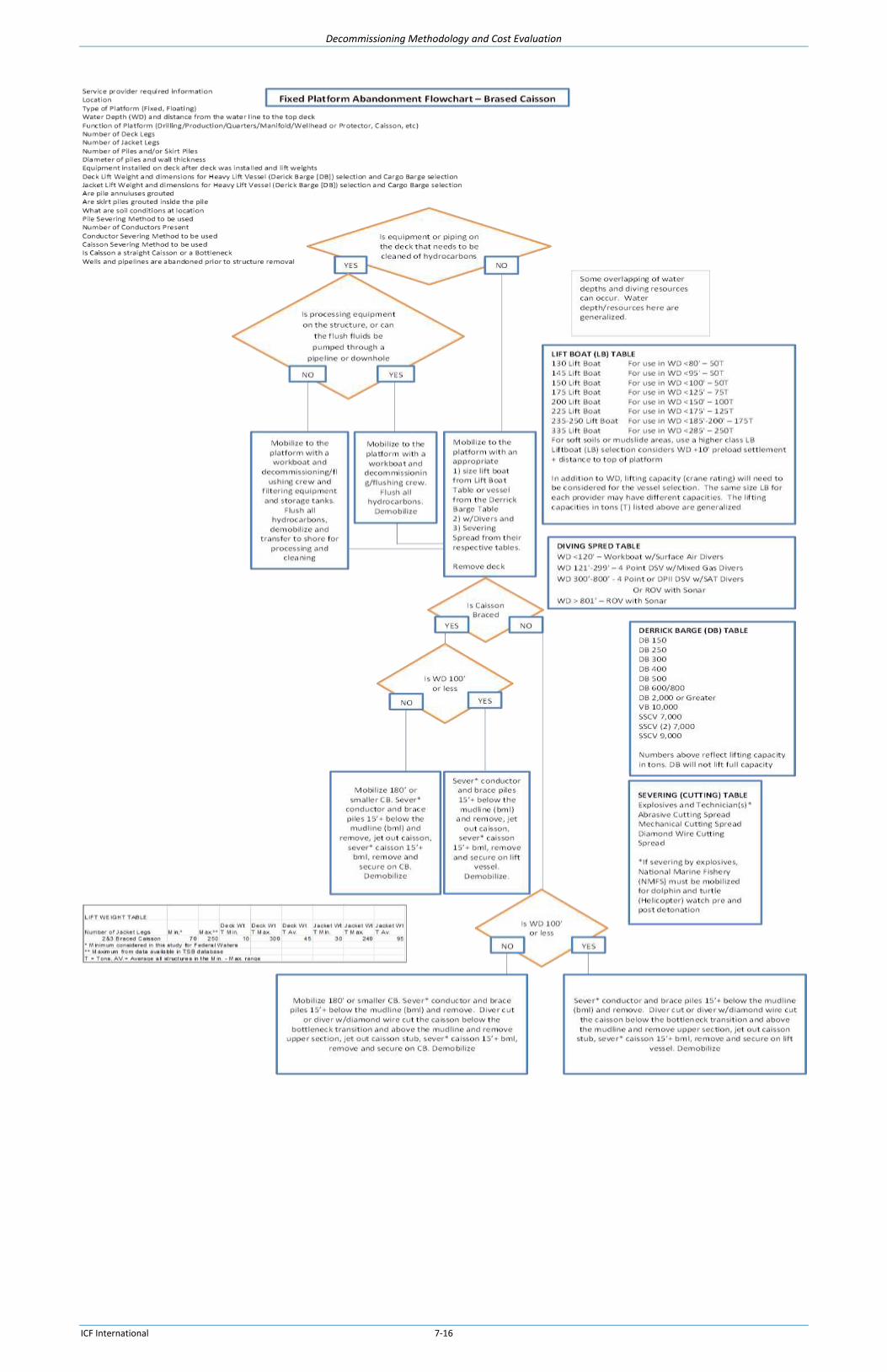
Decommissioning Methodology and Cost Evaluation
ICF International 7-16

Decommissioning Methodology and Cost Evaluation
ICF International 7-17

Decommissioning Methodology and Cost Evaluation
ICF International 7-18

Decommissioning Methodology and Cost Evaluation
ICF International 7-19
7.6.4.2. Floating Platforms
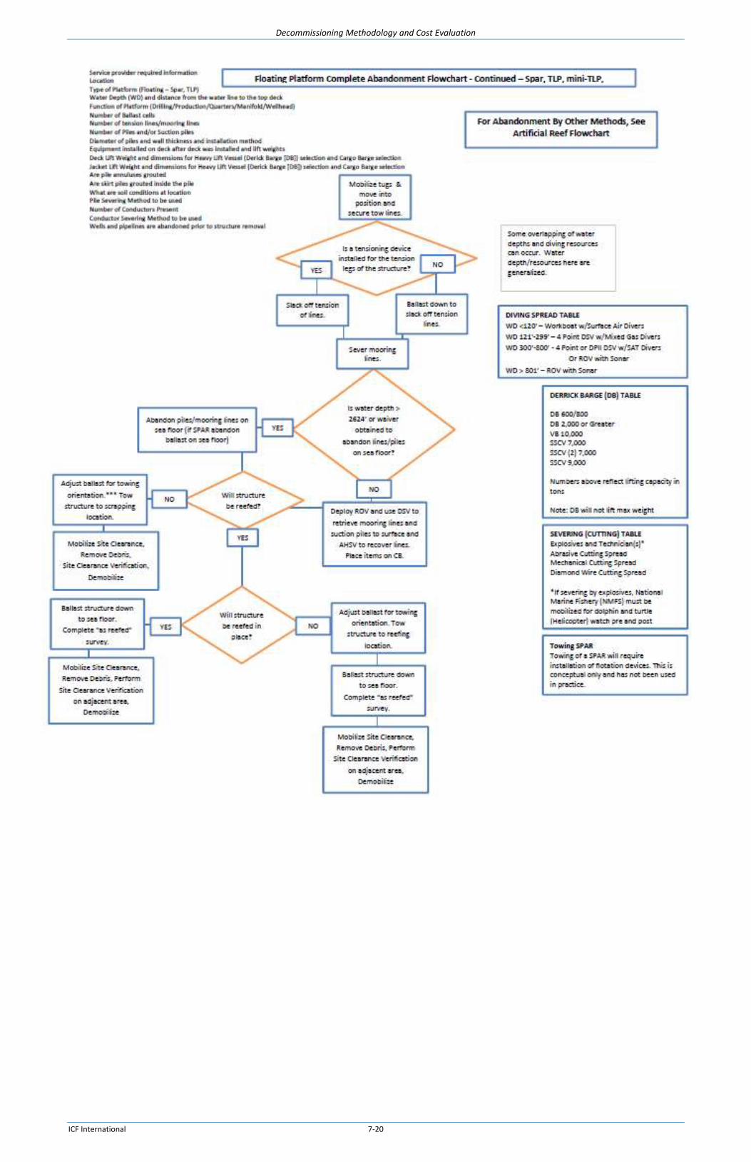
Decommissioning Methodology and Cost Evaluation
ICF International 7-20
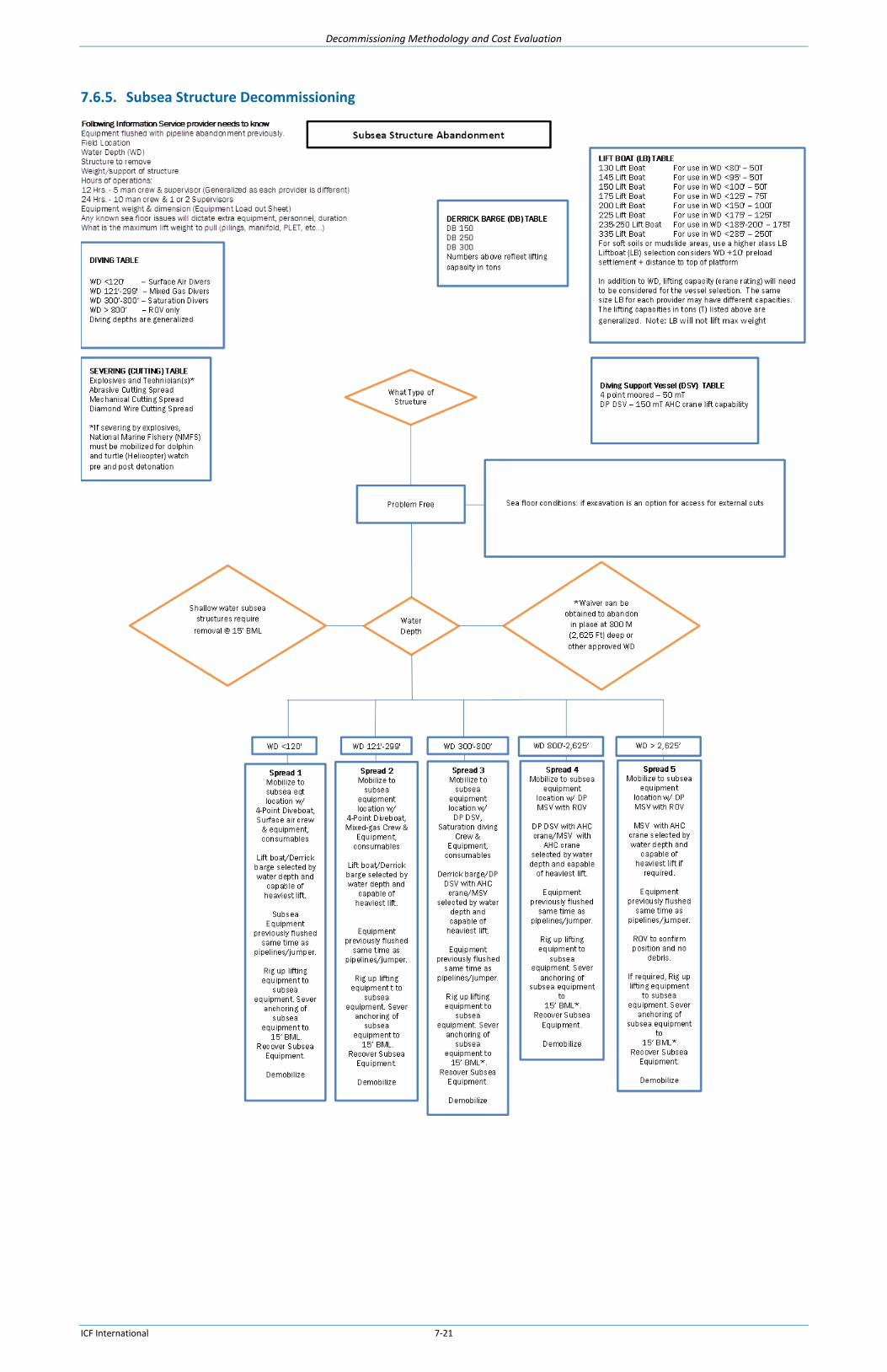
Decommissioning Methodology and Cost Evaluation
ICF International 7-21
7.6.5. Subsea Structure Decommissioning

Decommissioning Methodology and Cost Evaluation
ICF International 8-1
8. Decommissioning Costs
8.1. Introduction
This Section presents cost data to determine estimated decommissioning liabilities for typical fixed,
tethered and moored structures along with associated pipelines and wells. Because virtually all offshore
decommissioning in the US OCS has been done in the GOM OCS, the cost data presented reflects GOM
OCS experience only. To estimate decommissioning costs in other areas, a similar procedure would be
used to build up the total estimated cost but site specific costs would need to be determined for each
activity. Piece small removal and other unconventional methodologies are not considered in this project
due to lack of confidence in cost estimation accuracy10, but there has been indications that piece small
removal could be approximately 50% - 100% higher than conventional methodology11.
The estimates were developed in a manner that satisfies the reporting and audit requirements of
Financial Accounting Standards Board (FASB) Statement of Financial Accounting Standards No. 143,
“Accounting for Asset Retirement” (SFAS 143); i.e., what a willing third party would consider in today’s
costs with no future adjustments. This standard requires that scrap values, if any, be treated separately
from decommissioning costs for accounting purposes. The estimates presented here do not attempt to
estimate salvage or scrap values.
The costs included in this study are a snapshot-in-time, based on available information and resources
economically selected for use. All costs in this section are estimated assuming trouble-free operations
and have not considered sharing of resources or using new emerging technology. All resource costs are
for the GOM. Costs for other areas will be different.
The intent of this section is not to develop the decommissioning cost for a specifically named platform
but rather to identify the costs for a type of facility in a particular water depth and provide the
opportunity for the viewer to obtain similar cost conclusions. Therefore, where costs are included, for
simplicity and confidentiality the platform names / locations have been omitted. Since each facility will
have different quantities of wells and pipelines, the estimated costs are provided separately on a unit
basis. Backup data for the representative platform deterministic estimates are provided in the
Appendix.
There have only been 16 platforms removed from the GOM in water deeper than 400 ft in the last 20
years. This includes two Semisubmersibles, one MTLP, one Spar and twelve fixed platforms. During the
same time period 3,304 structures were removed from water depths less than 400 ft. Industry
estimates of platform removals from water deeper than 400 ft are based primarily on projections due to
this limited data compared to the abundance of data from shallower removals. Decommissioning service
10 http://decomnorthsea.com/uploads/pdfs/projects/ABB-Offshore-Oil-and-Gas-Decommissioning-2015.pdf
11
https://www.gov.uk/government/uploads/system/uploads/attachment_data/file/43411/inde-dp__1_.pdf
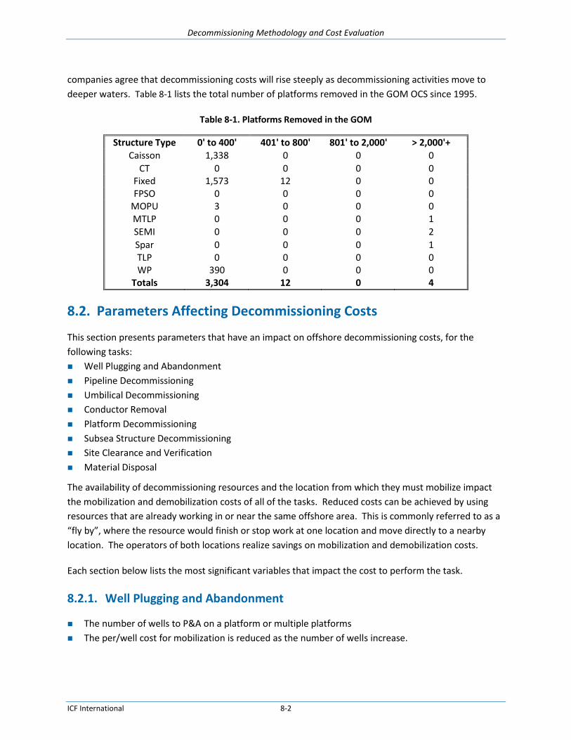
Decommissioning Methodology and Cost Evaluation
ICF International 8-2
companies agree that decommissioning costs will rise steeply as decommissioning activities move to
deeper waters. Table 8-1 lists the total number of platforms removed in the GOM OCS since 1995.
Table 8-1. Platforms Removed in the GOM
Structure Type 0' to 400' 401' to 800' 801' to 2,000' > 2,000'+ Caisson 1,338 0 0 0
CT 0 0 0 0 Fixed 1,573 12 0 0 FPSO 0 0 0 0
MOPU 3 0 0 0 MTLP 0 0 0 1 SEMI 0 0 0 2
Spar 0 0 0 1 TLP 0 0 0 0 WP 390 0 0 0
Totals 3,304 12 0 4
8.2. Parameters Affecting Decommissioning Costs
This section presents parameters that have an impact on offshore decommissioning costs, for the
following tasks:
Well Plugging and Abandonment
Pipeline Decommissioning
Umbilical Decommissioning
Conductor Removal
Platform Decommissioning
Subsea Structure Decommissioning
Site Clearance and Verification
Material Disposal
The availability of decommissioning resources and the location from which they must mobilize impact
the mobilization and demobilization costs of all of the tasks. Reduced costs can be achieved by using
resources that are already working in or near the same offshore area. This is commonly referred to as a
“fly by”, where the resource would finish or stop work at one location and move directly to a nearby
location. The operators of both locations realize savings on mobilization and demobilization costs.
Each section below lists the most significant variables that impact the cost to perform the task.
8.2.1. Well Plugging and Abandonment
The number of wells to P&A on a platform or multiple platforms
The per/well cost for mobilization is reduced as the number of wells increase.
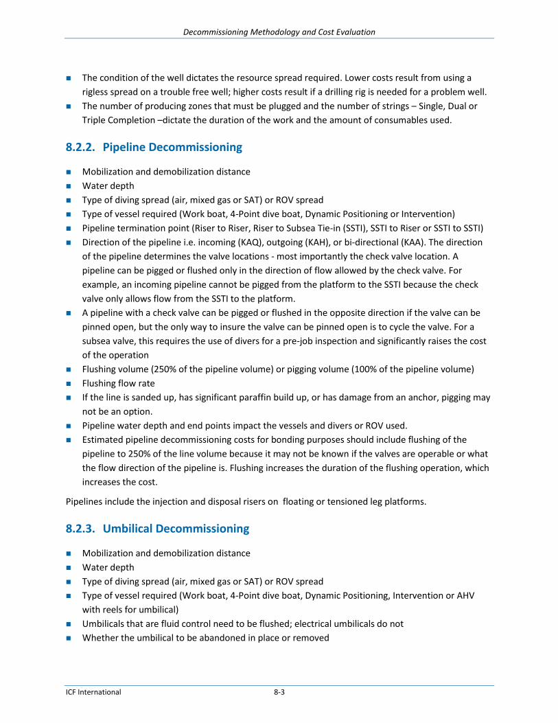
Decommissioning Methodology and Cost Evaluation
ICF International 8-3
The condition of the well dictates the resource spread required. Lower costs result from using a
rigless spread on a trouble free well; higher costs result if a drilling rig is needed for a problem well.
The number of producing zones that must be plugged and the number of strings – Single, Dual or
Triple Completion –dictate the duration of the work and the amount of consumables used.
8.2.2. Pipeline Decommissioning
Mobilization and demobilization distance
Water depth
Type of diving spread (air, mixed gas or SAT) or ROV spread
Type of vessel required (Work boat, 4-Point dive boat, Dynamic Positioning or Intervention)
Pipeline termination point (Riser to Riser, Riser to Subsea Tie-in (SSTI), SSTI to Riser or SSTI to SSTI)
Direction of the pipeline i.e. incoming (KAQ), outgoing (KAH), or bi-directional (KAA). The direction
of the pipeline determines the valve locations - most importantly the check valve location. A
pipeline can be pigged or flushed only in the direction of flow allowed by the check valve. For
example, an incoming pipeline cannot be pigged from the platform to the SSTI because the check
valve only allows flow from the SSTI to the platform.
A pipeline with a check valve can be pigged or flushed in the opposite direction if the valve can be
pinned open, but the only way to insure the valve can be pinned open is to cycle the valve. For a
subsea valve, this requires the use of divers for a pre-job inspection and significantly raises the cost
of the operation
Flushing volume (250% of the pipeline volume) or pigging volume (100% of the pipeline volume)
Flushing flow rate
If the line is sanded up, has significant paraffin build up, or has damage from an anchor, pigging may
not be an option.
Pipeline water depth and end points impact the vessels and divers or ROV used.
Estimated pipeline decommissioning costs for bonding purposes should include flushing of the
pipeline to 250% of the line volume because it may not be known if the valves are operable or what
the flow direction of the pipeline is. Flushing increases the duration of the flushing operation, which
increases the cost.
Pipelines include the injection and disposal risers on floating or tensioned leg platforms.
8.2.3. Umbilical Decommissioning
Mobilization and demobilization distance
Water depth
Type of diving spread (air, mixed gas or SAT) or ROV spread
Type of vessel required (Work boat, 4-Point dive boat, Dynamic Positioning, Intervention or AHV
with reels for umbilical)
Umbilicals that are fluid control need to be flushed; electrical umbilicals do not
Whether the umbilical to be abandoned in place or removed

Decommissioning Methodology and Cost Evaluation
ICF International 8-4
If the umbilical is not to be abandoned in place, the lifting weight, length and water depth must be
known for resource selection.
8.2.4. Conductor Removal
Removal of conductors during platform removal operations with the DB or prior to the arrival of the
DB. For deeper platforms, with many conductors, it is more cost effective to mobilize a severing and
removal spread prior to the DB arrival.
The conductor severing method - The lowest cost method is often severing with explosives.
However, delays are possible if protected marine life is found in the area.
If the conductor must be pulled through bell guides, explosive methods may flare the end and
prevent the conductor from passing through the guide. Abrasive or mechanical methods would be
preferred in this case.
If the platform does not have a crane of sufficient lift capacity, a portable crane must be installed or
casing jacks must be included in the work spread.
Conductor characteristics must be known for cutting method selection –
o Conductor Diameter,
Number of casing strings to be removed with the conductor,
o Whether casing strings are grouted, and
o Casing string diameter(s).
8.2.5. Platform Decommissioning
8.2.5.1. Fixed Platforms
Mobilization and demobilization distance
Water depth
Type of diving spread (air, mixed gas or SAT) or ROV spread
Any equipment or modifications added to the deck after deck installation must be reviewed as this
changes the original center of gravity (COG) and lifting design
All processing equipment and piping must be cleaned with all fluids processed either by onboard
process equipment, by processing equipment mobilized to the site, or by capturing in tank for
onshore processing
Deck and jack dimensions and lift weights must be known for DB and CB(s) selection
Whether the deck is planned to be cut up and removed in multiple lifts, e.g., 8-leg deck into two 4-
leg decks
If the piles are to be removed to reduce the jacket lift weight, explosive methods may flare the end
and prevent the pile from passing through the jacket leg. Abrasive or mechanical methods would be
preferred in this case

Decommissioning Methodology and Cost Evaluation
ICF International 8-5
If the piles have internal obstructions that would prohibit the use of internal severing tools, the piles
must be cut from the outside with DWC. Jetting tools assisted by divers or ROV will need to jet out
around each pile to place the DWC at the approved cutting depth BML.
If the jacket pile to leg annulus has been grouted, the piles cannot be removed and must be included
in the jacket lift weight calculations
Jacket final disposition - complete removal or reefing method
Jacket lifting and or cutting method must be determined, e.g., single lift, multiple lift, severing BWL
or hopping and severing AWL
8.2.5.2. Floating Platforms
Mobilization and demobilization distance
Water depth
Type of diving spread (air, mixed gas or SAT) or ROV spread
Whether the deck needs to be removed
All processing equipment and piping must be cleaned with all fluids processed either by onboard
process equipment, by processing equipment mobilized to the site, or by capturing in tank for
onshore processing
Number and type of lift weights of the mooring lines in the anchoring system, i.e. steel, polymer or
other cable, chain or a combination
If a TLP or MTLP, the number of steel pipes and the associated lift weights
Whether the anchor piles are to be removed or left in-place
Whether the anchoring system is to be removed or left in-place
The mooring to pile or tension leg to pile severing method
Whether the moorings must be severed from the hull or can be released
The mooring to hull or tension leg to hull severing method
The lift capacity of the DP HLV and CB selected affects the anchoring system sectioning and removal
plan
The number of tow tugs required to be transport the hull to a new location, refurbishing yard, or
scrap facility
8.2.6. Subsea Structure Decommissioning
Mobilization and demobilization distance
Water depth
Type of diving spread (air, mixed gas or SAT) or ROV spread
Whether the subsea structures, PLETs, PLEMs, UTAs, jumpers, etc., will be removed or left in-place
Whether the structures are directly anchored to the seabed or installed over anchored templates
Whether the templates will be removed or approved to be left in-place
The method of severing any anchor piles
If the structures are removed, the dimensions, lift weights and water depth will drive the choice of
removal spread

Decommissioning Methodology and Cost Evaluation
ICF International 8-6
8.2.7. Site Clearance and Verification
Mobilization and demobilization distance
Water depth
Whether trawling is required
Whether an alternate method is approved
Age of platform – In general the older the platform, the more debris
8.2.8. Material Disposal
There are three primary methods of disposal for steel and other materials associated with dismantling a
platform: refurbish and reuse, scrap and recycle, and dispose of in designated landfills. Opportunities
for refurbishing and reusing facilities are very limited due to the limitations associated with meeting the
strict technical standards now required, so most material is recycled.
There are quite a number of steel scrap yards along the Gulf Coast that receive production equipment
from decommissioned offshore production facilities. Scrap steel recycling is a big business, as platforms,
pipelines, floating production systems, and subsea production systems are brought ashore. During the
year 2007, scrap steel delivered to the dock in Morgan City, Louisiana was sold to scrap dealers for
about $300 per ton. The year 2008 saw a collapse in the scrap steel market, and scrap yards charged
contractors $75 per ton to unload steel platforms. In 2015 scrap steel is bringing $70 to $130 per ton at
the dock in Morgan City. Scrap may also be exported to China, India, South Korea, Turkey or other
countries, depending on market prices.
The scrap yards receiving large components must process the material by cutting it into smaller pieces,
typically 2’ x 5’ maximum, to meet the size requirements of secondary smelters. The value of the large
pieces may be $150/ton to $200/ton less than the spot price of scrap steel at the mill to account for this
processing and transportation. Therefore, when steel prices are high, the offshore components may
yield a profit when delivered to the scrap yard but when steel prices are low the scrap yard may charge
to accept the steel. The scrap metal must be sorted to separate galvanized steel, stainless steel, and
other metals from carbon steel.
Southern Recycling on the water front in Morgan City, Louisiana has been in the platform recycling
business for over 40 years, and they have been recycling since 1902. Pictures of this scrap yard are
shown in Figure 8-1 and Figure 8-2. Their 400 ton lift capacity crane unloads offshore platforms in large
pieces, which are then cut up for shipment to the steel mills. Southern Recycling places some high value
offshore platforms in storage with their joint venture partner Allison Marine for possible reuse as an
offshore production platform.

Decommissioning Methodology and Cost Evaluation
ICF International 8-7
Figure 8-1. Southern Scrap Yard Morgan City
Figure 8-2. Southern Scrap Yard
(Photo courtesy of Southern Scrap)

Decommissioning Methodology and Cost Evaluation
ICF International 8-8
There are numerous other sites along the gulf coast of varying sizes that could be used as scrap facilities.
The Gulf Marine Fabricators facility in Ingleside, Texas, though not configured as a scrap facility, could
also be used as a disposal site or a site to reconfigure jackets for further use. See Figure 8-3 and Figure
8-4. The draft requirements would allow use of flotation devices and floating the jackets to their deep
water facility for some of the jackets included in this study. For the larger ones, this would not be an
option. For example, the Bullwinkle structure in 1,348’ water depth has a jacket base dimension of 300’
X 350’ and even partially submerged using flotation devices, the structure would exceed the 45’
minimum channel draft.
Figure 8-3. Gulf Marine Fabricators Yard
(Photo courtesy of Gulf Marine)

Decommissioning Methodology and Cost Evaluation
ICF International 8-9
Figure 8-4. Gulf Marine Fabricators
(Drawing courtesy of Gulf Marine Fabricators)
8.3. Estimated Costs
This section presents estimated costs for each major component of decommissioning. Each subsection
provides a description and either a stated cost or table(s) from which the user can select costs.
Engineering and Project Management
Well Plugging and Abandonment
Pipeline Abandonment
Umbilical Decommissioning
Conductor Decommissioning
Platform Decommissioning
Fixed Platforms
Floating Platforms
8.3.1. Planning, Engineering, Project Management, Weather Contingency and Work Provision
Costs for planning, engineering, project management, weather contingency and work provision are not
usually calculated directly but are estimated as percentages of the directly estimated costs.

Decommissioning Methodology and Cost Evaluation
ICF International 8-10
8.3.1.1. Planning, Engineering, Project Management
The project management, engineering and planning phase of the decommissioning process will typically
need to begin at a minimum of two to three years before production ceases and involves a review of
contractual obligations, engineering analysis, operational planning, and contracting. These would be in-
house operator costs with cost input from service providers. The first step involves conducting a
detailed review of all records and decommissioning requirements including lease, operating,
production/unit, pipeline, and production sales agreements. A detailed engineering analysis is also
conducted of drilling records, as-built drawings, construction reports, maintenance records and
inspection reports. Field inspections are done to verify the structural integrity of the platform and
examine the present condition of the wellheads and equipment. Based on this information, detailed
engineering plans are developed for plugging and abandoning the wells, decommission the pipelines,
severing the conductors and piles, removing the conductors, removing the piles if necessary, removing
the topsides and jacket, and disposing of the materials. Concurrently, a comprehensive survey of
decommissioning vessels and equipment is made to determine their availability and cost. Bids are then
solicited and contractors selected.
The costs of project management, engineering and planning for decommissioning an offshore structure
can vary widely, depending on the corporate structure, type of platform, its size, water depth, removal
procedures, and transportation and disposal options. For the actual offshore work an analysis of
historical decommissioning costs over a 30 year period yielded an approximate 8% cost for Project
Management and Engineering (Eng/PM). This is in line with multiple evaluations of decommissioning
projects where the percentage of operator costs for Operator Project Management is reported at 8%.
The Eng/PM costs are based on the subtotal with the Mob/Demob costs. The cost information was
obtained from a TSB in-house database that compiles cost data on oil and gas platform
decommissioning projects in the Gulf of Mexico. The operator up-front planning and operational
monitoring is not included in this 8% and would be an additional estimated 3%-4% for a small project
like a caisson removal to 1%-1.5% for a large fixed platform in deep water. This is based on TSB
experience and is not based on operator input as operators hold this information confidentially. If an
operator were to go out of business and no other operators were liable for the ARO, BSEE would incur
this cost either directly or through a third party.
8.3.1.2. Weather Contingency Allowance
A weather allowance (often referred to as contingency) of 20% is used in the estimates in this study.
See Chapter 9 for a discussion of Contingency. Weather allowance cost is based on the subtotal without
the Mob/Demob and is based on vessel on-location costs.
8.3.1.3. Work Provision
A work provision of 15% is included in the estimates in this study. TSB’s Platform Abandonment
Estimating System (PAES®) program used to generate the estimates in this study has historically been
benchmarked against actual decommissioning projects in the GOM that TSB has managed or performed.

Decommissioning Methodology and Cost Evaluation
ICF International 8-11
Since the development of the PAES® program and during the benchmarking phase, the actual total
decommissioning costs have consistently been about 15% over the estimated cost of the major
decommissioning activities. This 15% has not been allocated to the numerous individual tasks involved
in virtually hundreds of decommissioning scenarios, but is included as a line item in the estimates to
capture these industry costs. This is not extra work or work contingency, but includes activities
necessary for actual removals that are not currently itemized in the estimates. Work Provision cost is
based on the subtotal without the Mob/Demob costs.
8.3.2. Well Plugging and Abandonment
8.3.2.1. Dry Tree Wells, Water Depth 50 ft to 400 ft
For the purpose of this study, it was assumed that the well casings were grouted to the surface, the 9-
5/8” and smaller strings were pulled during Temporary Abandonment (T&A) operations, and the
remainder were pulled during conductor severing and removal. Typically the well abandonment is
completed in the T&A stage and the conductors are severed and removed during platform removal
operations using a DB. The well abandonment costs in this study are for T&A operations; the conductor
costs are estimated elsewhere in this study. The wells were estimated as typical trouble-free wells
plugged using rigless methods. Additional costs due to well abandonment complications such as stuck
valves, collapsed casing, or fouling with sand, paraffin, or other materials are highly dependent on the
individual well circumstances and require evaluation of the current well bore schematics and well
history. Costs associated with problematic wells are outside the scope of this study.
Operators need to confirm if wells can be accessed with rigless methods or require other methods. The
estimates here are generic and include the work provision, weather and engineering percentages as
discussed earlier in this chapter. The estimates presented are for trouble-free wells using rigless
methods from the platform.
For wells on platforms in WDs of 50’ to 400’, a representative platform in the midrange of 200’ WD was
selected with a mobilization distance of 103 NM using a workboat at 8 knots per hour plus 12 hours
dock time. Table 8-2 shows the range in costs on this platform with for configurations with from 1 well
up to 20 wells. The total estimated costs are plotted in Figure 8-5 and the estimated per well costs are
plotted in Figure 8-6.
The estimated cost is built up from the unit costs of individual components and needs to be adjusted for
the specific circumstances of each platform and project. The equations below illustrate the components
that go into the formula for a representative well P&A cost estimate. The specific values will depend on
the spreads used in the estimates.
𝐶𝑜𝑠𝑡 = 𝑀𝑜𝑏𝑖𝑙𝑖𝑧𝑎𝑡𝑖𝑜𝑛 𝑐𝑜𝑠𝑡 + 𝑆𝑒𝑡𝑢𝑝 𝑐𝑜𝑠𝑡 + 𝑃&𝐴 𝑐𝑜𝑠𝑡 + 𝑅𝑖𝑔 𝑑𝑜𝑤𝑛 𝑐𝑜𝑠𝑡 + 𝐷𝑒𝑚𝑜𝑏𝑖𝑙𝑖𝑧𝑎𝑡𝑖𝑜𝑛 𝑐𝑜𝑠𝑡
+ 𝑊𝑜𝑟𝑘 𝑝𝑟𝑜𝑣𝑖𝑠𝑖𝑜𝑛 + 𝑊𝑒𝑎𝑡ℎ𝑒𝑟 𝑐𝑜𝑛𝑡𝑖𝑛𝑔𝑒𝑛𝑐𝑦
+ 𝐸𝑛𝑔𝑖𝑛𝑒𝑒𝑟𝑖𝑛𝑔/𝑃𝑟𝑜𝑗𝑒𝑐𝑡 𝑀𝑎𝑛𝑎𝑔𝑒𝑚𝑒𝑛𝑡 𝑐𝑜𝑠𝑡

Decommissioning Methodology and Cost Evaluation
ICF International 8-12
𝑀𝑜𝑏𝑖𝑙𝑖𝑧𝑎𝑡𝑖𝑜𝑛 𝑐𝑜𝑠𝑡 = 𝑊𝑜𝑟𝑘𝑏𝑜𝑎𝑡 ℎ𝑜𝑢𝑟𝑙𝑦 𝑟𝑎𝑡𝑒 ∗ (12 ℎ𝑟 + 𝑀𝑜𝑏 𝑑𝑖𝑠𝑡𝑎𝑛𝑐𝑒/𝑏𝑜𝑎𝑡 𝑠𝑝𝑒𝑒𝑑)
𝑆𝑒𝑡𝑢𝑝 𝑐𝑜𝑠𝑡 = 𝑆𝑒𝑡𝑢𝑝 ℎ𝑜𝑢𝑟𝑙𝑦 𝑟𝑎𝑡𝑒 ∗ 4 ℎ𝑟/𝑤𝑒𝑙𝑙 ∗ 𝑁𝑜. 𝑜𝑓 𝑤𝑒𝑙𝑙𝑠
𝑃&𝐴 𝑐𝑜𝑠𝑡 = 𝑃&𝐴 ℎ𝑜𝑢𝑟𝑙𝑦 𝑟𝑎𝑡𝑒 ∗ 84 ℎ𝑟/𝑤𝑒𝑙𝑙 ∗ 𝑁𝑜. 𝑜𝑓 𝑤𝑒𝑙𝑙𝑠
𝑅𝑖𝑔 𝑑𝑜𝑤𝑛 𝑐𝑜𝑠𝑡 = 𝑅𝑖𝑔 𝑑𝑜𝑤𝑛 ℎ𝑜𝑢𝑟𝑙𝑦 𝑟𝑎𝑡𝑒 ∗ 4 ℎ𝑟 𝑤𝑒𝑙𝑙⁄ ∗ 𝑁𝑜. 𝑜𝑓 𝑤𝑒𝑙𝑙𝑠
𝐷𝑒𝑚𝑜𝑏𝑖𝑙𝑖𝑧𝑎𝑡𝑖𝑜𝑛 𝑐𝑜𝑠𝑡 = 𝑊𝑜𝑟𝑘𝑏𝑜𝑎𝑡 ℎ𝑜𝑢𝑟𝑙𝑦 𝑟𝑎𝑡𝑒 ∗ (12 ℎ𝑟 + 𝑀𝑜𝑏 𝑑𝑖𝑠𝑡𝑎𝑛𝑐𝑒 𝑏𝑜𝑎𝑡⁄ 𝑠𝑝𝑒𝑒𝑑)
𝐸𝑛𝑔 𝑃𝑀⁄ 𝑐𝑜𝑠𝑡 = 8% ∗ (𝑀𝑜𝑏 𝑐𝑜𝑠𝑡 + 𝑆𝑒𝑡𝑢𝑝 𝑐𝑜𝑠𝑡 + 𝑃&𝐴 𝑐𝑜𝑠𝑡 + 𝑅𝑖𝑔 𝑑𝑜𝑤𝑛 𝑐𝑜𝑠𝑡 + 𝐷𝑒𝑚𝑜𝑏 𝑐𝑜𝑠𝑡)
𝑊𝑒𝑎𝑡ℎ𝑒𝑟 𝑐𝑜𝑛𝑡𝑖𝑛𝑔𝑒𝑛𝑐𝑦 = 20% ∗ (𝑆𝑒𝑡𝑢𝑝 𝑐𝑜𝑠𝑡 + 𝑃&𝐴 𝑐𝑜𝑠𝑡 + 𝑅𝑖𝑔 𝑑𝑜𝑤𝑛 𝑐𝑜𝑠𝑡)
𝑊𝑜𝑟𝑘 𝑝𝑟𝑜𝑣𝑖𝑠𝑖𝑜𝑛 = 15% ∗ (𝑆𝑒𝑡𝑢𝑝 𝑐𝑜𝑠𝑡 + 𝑃&𝐴 𝑐𝑜𝑠𝑡 + 𝑅𝑖𝑔 𝑑𝑜𝑤𝑛 𝑐𝑜𝑠𝑡)
Table 8-2. Dry Tree Well T&A in WD 50’ to 400’
20 Wells 15 Wells 10 Wells 5 Wells 1 Well
Task Hours Cost Hours Cost Hours Cost Hours Cost Hours Cost
Mob P&A Spread (Hr) #24 25 $37,743 25 $37,743 25 $37,743 25 $37,743 25 $37,743
Setup on Platform & All Wells (Hr) #11 80 $121,360 60 $91,020 40 $60,680 20 $30,340 4 $6,068
P&A Wells on Platform (Hr) #28 1680 $4,517,120 1260 $3,387,840 840 $2,258,560 420 $1,129,280 84 $225,856
Rig Down from All Wells & Platform (Hr) #12 80 $121,360 60 $91,020 40 $60,680 20 $30,340 4 $6,068
Demob P&A Spread (Hr) #25 25 $37,743 25 $37,743 25 $37,743 25 $37,743 25 $37,743
Work Provision - 15% (w/0 Mob/Demob) $713,976 $535,482 $356,988 $178,494 $35,699
Weather Contingency - 20% (w/o Mob/Demob) $951,968 $713,976 $475,984 $237,992 $47,598
Engineering & PM - 8% (w/ Mob/Demob) $386,826 $291,629 $196,432 $101,236 $25,078
Total All Wells $6,888,096 $5,186,453 $3,484,810 $1,783,168 $421,853
Cost per Well $344,405 $345,764 $348,481 $356,634 $421,853
Decommissioning Methodology and Cost Evaluation
ICF International 8-13
Figure 8-5. Total Well Costs
Figure 8-6. Per Well Costs
8.3.2.2. Dry Tree Wells, Water Depth over 400 ft
The typical platform crane of 25 tons is insufficient to pull the 9-5/8” casing on platforms in water
depths greater than 400 ft, therefore all strings were estimated to be pulled with casing jacks. The
typical T&A spread and operation durations are shown in Table 8-3 for problem free, accessible, dry tree
wells.
$0
$1,000,000
$2,000,000
$3,000,000
$4,000,000
$5,000,000
$6,000,000
$7,000,000
$8,000,000
20 Wells15 Wells10 Wells5 Wells1 Well
Total All Wells
$0
$50,000
$100,000
$150,000
$200,000
$250,000
$300,000
$350,000
$400,000
$450,000
20 Wells15 Wells10 Wells5 Wells1 Well
Cost per Well

Decommissioning Methodology and Cost Evaluation
ICF International 8-14
Table 8-3. Well T&A Basic Parameters with Casing Jacks
The cost to T&A dry tree wells at water depths from 400’ to 5,000’ were estimated for a platform with
60 wells as shown in Table 8-4. Mobilization duration is based on distances to average water depth
curves using a workboat at 8 knots per hour plus 12 hours dock time. Fixed platforms have dry tree wells
in water depths from 400’ to about 1,800’. TLPs have dry tree wells in water depths from about 1,500’
to >4,600’. The costs were estimated at well counts from 1 to 60 wells and then normalized to the cost
per well. Figure 8-7 shows the cost per well as a function of water depth and number of wells on a
platform. The mobilization and demobilization costs are distributed among all of the wells. Table 8-4
shows the well P&A costs for various platforms with 60 wells.
Well T&A costs for platforms with other well counts in varying water depths can be obtained from either
Figure 8-7 or Figure 8-8. For example the cost of 60 platform wells in 1,800’ in Table 8-4 is $45 MM.
Using Figure 8-7 at 1,800’ the 60 well curve shows $754K per well. Multiplying this times 60 wells equals
$45 MM. Using Figure 8-8 at 1,800’ the 60 well curve shows a unit cost of $419 per foot of water depth
per well. Using $419/ft-well multiplied by the water depth of 1,800’ and further multiplying by the 60
wells yields a total well T&A cost of $45 MM.

Decommissioning Methodology and Cost Evaluation
ICF International 8-15
Table 8-4. Dry Tree Well T&A in WD >/= 400’, 60 Wells per platform
Water
Depth Ft. Dia in. #/' ft. tons
Mob
/Demob
hrs each
Setup &
Rig
down
hrs each
Typ.
T&A per
well hrs
w/50%
cut and
pull
Added
T&A
hours per
water
depth per
well
Pull
/Cut
per
well
hrs
Total cost
per well w/o
Setup &
Mob
/Demob
Total cost per
platform wells
Total cost for 60
platform wells
w/Work
Provision,
Engineeering
and Weather
Total cost
per platform
normalized
to 1 well
400 9-5/8 53.5 928 24.8 30 12 48 14 35 $331,547 $20,132,304 $28,789,195 $479,820
500 9-5/8 53.5 1028 27.5 31 12 48 15 39 $345,802 $20,993,306 $30,020,428 $500,340
600 9-5/8 53.5 1128 30.2 32 12 48 16 43 $360,057 $21,854,308 $31,251,660 $520,861
700 9-5/8 53.5 1228 32.8 33 12 48 17 47 $374,312 $22,715,310 $32,482,893 $541,382
800 9-5/8 53.5 1328 35.5 34 12 48 18 50 $385,716 $23,405,252 $33,469,510 $557,825
900 9-5/8 53.5 1428 38.2 35 12 48 19 54 $399,971 $24,266,254 $34,700,743 $578,346
1000 9-5/8 53.5 1528 40.9 36 12 48 20 58 $414,226 $25,127,256 $35,931,976 $598,866
1100 9-5/8 53.5 1628 43.5 37 12 48 21 62 $428,481 $25,988,258 $37,163,209 $619,387
1200 9-5/8 53.5 1728 46.2 38 12 48 22 65 $439,885 $26,678,200 $38,149,826 $635,830
1300 9-5/8 53.5 1828 48.9 39 12 48 23 69 $454,140 $27,539,202 $39,381,059 $656,351
1400 9-5/8 53.5 1928 51.6 40 12 48 24 73 $468,395 $28,400,204 $40,612,292 $676,872
1500 9-5/8 53.5 2028 54.2 41 12 48 25 77 $482,650 $29,261,206 $41,843,525 $697,392
1600 9-5/8 53.5 2128 56.9 42 12 48 26 80 $494,054 $29,951,148 $42,830,142 $713,836
1700 9-5/8 53.5 2228 59.6 43 12 48 27 84 $508,309 $30,812,150 $44,061,375 $734,356
1800 9-5/8 53.5 2328 62.3 44 12 48 28 88 $522,564 $31,673,152 $45,292,607 $754,877
1900 9-5/8 53.5 2428 64.9 44 12 48 29 92 $536,819 $32,528,452 $46,515,686 $775,261
2000 9-5/8 53.5 2528 67.6 44 12 48 30 95 $548,223 $33,212,692 $47,494,150 $791,569
2100 9-5/8 53.5 2628 70.3 44 12 48 31 99 $562,478 $34,067,992 $48,717,229 $811,954
2200 9-5/8 53.5 2728 73.0 44 12 48 32 103 $576,733 $34,923,292 $49,940,308 $832,338
2300 9-5/8 53.5 2828 75.6 44 12 48 33 107 $590,988 $35,778,592 $51,163,387 $852,723
2400 9-5/8 53.5 2928 78.3 44 12 48 34 110 $602,392 $36,462,832 $52,141,850 $869,031
2500 9-5/8 53.5 3028 81.0 44 12 48 35 114 $616,647 $37,318,132 $53,364,929 $889,415
2600 9-5/8 53.5 3128 83.7 44 12 48 36 118 $630,902 $38,173,432 $54,588,008 $909,800
2700 9-5/8 53.5 3228 86.3 44 12 48 37 122 $645,157 $39,028,732 $55,811,087 $930,185
2800 9-5/8 53.5 3328 89.0 44 12 48 38 125 $656,561 $39,712,972 $56,789,550 $946,492
2900 9-5/8 53.5 3428 91.7 44 12 48 39 129 $670,816 $40,568,272 $58,012,629 $966,877
3000 9-5/8 53.5 3528 94.4 44 12 48 40 133 $685,071 $41,423,572 $59,235,708 $987,262
3100 9-5/8 53.5 3628 97.0 44 12 48 41 137 $699,326 $42,278,872 $60,458,787 $1,007,646
3200 9-5/8 53.5 3728 99.7 44 12 48 42 140 $710,730 $42,963,112 $61,437,250 $1,023,954
3300 9-5/8 53.5 3828 102.4 44 12 48 43 144 $724,985 $43,818,412 $62,660,329 $1,044,339
3400 9-5/8 53.5 3928 105.1 44 12 48 44 148 $739,240 $44,673,712 $63,883,408 $1,064,723
3500 9-5/8 53.5 4028 107.7 44 12 48 45 152 $753,495 $45,529,012 $65,106,487 $1,085,108
3600 9-5/8 53.5 4128 110.4 44 12 48 46 155 $764,899 $46,213,252 $66,084,950 $1,101,416
3700 9-5/8 53.5 4228 113.1 44 12 48 47 159 $779,154 $47,068,552 $67,308,029 $1,121,800
3800 9-5/8 53.5 4328 115.8 44 12 48 48 163 $793,409 $47,923,852 $68,531,108 $1,142,185
3900 9-5/8 53.5 4428 118.4 44 12 48 49 167 $807,664 $48,779,152 $69,754,187 $1,162,570
4000 9-5/8 53.5 4528 121.1 44 12 48 50 170 $819,068 $49,463,392 $70,732,651 $1,178,878
4100 9-5/8 53.5 4628 123.8 44 12 48 51 174 $833,323 $50,318,692 $71,955,730 $1,199,262
4200 9-5/8 53.5 4728 126.5 44 12 48 52 178 $847,578 $51,173,992 $73,178,809 $1,219,647
4300 9-5/8 53.5 4828 129.1 44 12 48 53 182 $861,833 $52,029,292 $74,401,888 $1,240,031
4400 9-5/8 53.5 4928 131.8 44 12 48 54 185 $873,237 $52,713,532 $75,380,351 $1,256,339
4500 9-5/8 53.5 5028 134.5 44 12 48 55 189 $887,492 $53,568,832 $76,603,430 $1,276,724
4600 9-5/8 53.5 5128 137.2 44 12 48 56 193 $901,747 $54,424,132 $77,826,509 $1,297,108
4700 9-5/8 53.5 5228 139.8 44 12 48 57 197 $916,002 $55,279,432 $79,049,588 $1,317,493
4800 9-5/8 53.5 5328 142.5 44 12 48 58 200 $927,406 $55,963,672 $80,028,051 $1,333,801
4900 9-5/8 53.5 5428 145.2 44 12 48 59 204 $941,661 $56,818,972 $81,251,130 $1,354,185
5000 9-5/8 53.5 5528 147.9 44 12 48 60 208 $955,916 $57,674,272 $82,474,209 $1,374,570
Typ. Strings to pull during T&A 7" @ 29#/ft or 9-5/8" @ 53.50 #/ft
(Assumes 13"+26"+30" grouted and pulled during PLTF Prep)
Using typical platform crane at 25 st and typical largest string to pull during T&A (9-5/8"), at
400' WD the crane capacity is exceeded and therefore casing jacks are necessary for all platform P&A >400' WD (A leap frog crane could also be installed when some of the strings
are removed - saving time)

Decommissioning Methodology and Cost Evaluation
ICF International 8-16
Figure 8-7. T&A Cost per Well as a Function of WD and Number of Wells
Figure 8-8. T&A Cost per Foot of Well as a Function of WD and Number of Wells
Decommissioning Methodology and Cost Evaluation
ICF International 8-17
8.3.2.3. Wet Tree Wells
Wet tree well plugging and abandonment is performed to achieve the same results on subsea wells as a
standard well plug and abandonment. The same barriers are required to be placed and tested. The key
difference is that a standalone vessel MSV (Non-MODU) or rig (MODU, semi-submersible or drillship) is
required to connect to the well and gain access to the wellbore. This greatly increases the cost. The
single largest contributing factor to cost is the rig or vessel.
There is additional risk of environmental impact. As stated, the wellbore must be accessed to allow
barriers to be put into place. The additional steps, connections and devices to maintain pressure control
(well control in a worst case scenario) introduce additional risk. This is similar to the risk exposure in a
drilling situation except that the well pressures and fluids are known during P&A. This allows for fluid
preparation to maintain well control.
The additional interfaces and services required increase the complexity. The well design also makes the
well abandonment more complicated than dry tree well P&A. There are normally additional annuli due
to more casings and liners run for a subsea well completion in the Gulf of Mexico. This requires
additional steps to seal off the barriers or to cut and remove the casing to gain access to the annuli. A
subsea well abandonment requires additional planning to ensure that isolation of the zones and annuli
are achieved on a first attempt. Any additional operations would significantly increase the cost of the
abandonment.
Some companies require the use of a MODU for subsea well abandonment. The additional capabilities
of a full rig can reduce additional time requirements if any issues occur during the well abandonment. If
the company has a long term contract with a rig this can be cost effective.
With the newly developed technology and equipment, an MSV (non-MODU) can perform the required
abandonment if approval to abandon the wellhead in place is granted by BSEE regulations to provide a
waiver if water depth exceeds 800 meters, doesn’t cause an obstruction, or poses safety concerns.
Methodology to perform well P&A without riser and rig is gaining acceptance in the oil and gas industry,
for example: Wild Well Control’s DeepRange used in Gulf of Mexico and West Africa, and The Cross
Group’s CROSS package used in Gulf of Mexico. This methodology reduces daily spread rate and allows a
cheaper alternative to using a full rig. There are situations where achieving the full abandonment may
not be possible. This risk needs to be quantified during the method selection stage of the well
abandonment to ensure the best method is selected for the job.
Another basic alternative is to use an MSV-T (MSV with Tower). The MSV-T has a tower for higher lifting
capability allowing tripping pipe and running a riser. The same operation as a rig is performed, but the
daily spread rate is less.
Some companies prefer combining the use of a non-MODU and MODU to limit the total time required
for an MODU to be on location. A non-MODU (MSV or alternative) can perform the lower abandonment
(isolating the reservoir from the wellbore and placing annuli barriers in place), and a MODU can arrive at
Decommissioning Methodology and Cost Evaluation
ICF International 8-18
a later planned date to perform the upper abandonment (surface plug, cut and recover casing if
required, and cutting and recovering wellhead if required).
Each subsea well needs to be reviewed for a proper abandonment estimate. Some subsea well
structures will require additional time for access to place barriers into additional locations (multiple
zone well, extra casings, etc.). Generally the abandonment duration is based on water depth,
perforations (reservoir access – screens), and packer depth. The key impact is water depth.
Figure 8-9 shows the relationship between water depth and subsea well P&A duration. Figure 8-10
shows the relationship of WD to cost. These are simplified examples based on drillship (MODU) at
$450,000 per day, MSV (Non-MODU) at $260,000 per day, services required for well abandonment, and
time for abandonment. Mobilization costs are not included. The mobilization costs can significantly
impact selection of method. A total cost review based on abandonment, mobilization, demobilization,
and travel between wells should be considered for a cost effective selection.
The approximate costs of a total spread are $674,600/day for a MODU spread and $466,000/day for a
non-MODU spread. These are rough estimates based on current day rate and service rates from several
vendors. Discounts could be negotiated based on the scope and amount of work to be done. Due to low
oil prices, some service providers are starting to lower resource rates. Also, some company
requirements for operations require additional equipment that may not be included. The formula below
can be used for a rough estimate.
𝑀𝑂𝐷𝑈 = [(𝑀𝑜𝑏 + 𝐷𝑒𝑚𝑜𝑏) ∗ (1 + 𝐸𝑛𝑔 𝑃𝑀⁄ ) + (𝑂𝑝𝑒𝑟𝑎𝑡𝑖𝑜𝑛𝑠 𝑡𝑖𝑚𝑒) ∗ (1 + 𝑊𝑒𝑎𝑡ℎ𝑒𝑟 + 𝑊𝑜𝑟𝑘
+ 𝐸𝑛𝑔 𝑃𝑀⁄ )] ∗ (𝑀𝑂𝐷𝑈 𝑟𝑎𝑡𝑒)
𝑁𝑜𝑛𝑀𝑂𝐷𝑈 = [(𝑀𝑜𝑏 + 𝐷𝑒𝑚𝑜𝑏) ∗ (1 + 𝐸𝑛𝑔 𝑃𝑀⁄ ) + (𝑂𝑝𝑒𝑟𝑎𝑡𝑖𝑜𝑛𝑠 𝑡𝑖𝑚𝑒) ∗ (1 + 𝑊𝑒𝑎𝑡ℎ𝑒𝑟 + 𝑊𝑜𝑟𝑘
+ 𝐸𝑛𝑔 𝑃𝑀⁄ )] ∗ (𝑁𝑜𝑛𝑀𝑂𝐷𝑈 𝑟𝑎𝑡𝑒)
𝑁𝑜𝑛𝑀𝑂𝐷𝑈 𝐿𝑜𝑤𝑒𝑟 & 𝑀𝑂𝐷𝑈 𝑈𝑝𝑝𝑒𝑟
= (𝑀𝑜𝑏 + 𝐷𝑒𝑚𝑜𝑏) ∗ (𝑁𝑜𝑛𝑀𝑂𝐷𝑈 𝑟𝑎𝑡𝑒) ∗ (1 + 𝐸𝑛𝑔 𝑃𝑀⁄ )
+ (𝑂𝑝𝑒𝑟𝑎𝑡𝑖𝑜𝑛𝑠 𝑡𝑖𝑚𝑒 𝑜𝑓 𝑁𝑜𝑛𝑀𝑂𝐷𝑈) ∗ (𝑁𝑜𝑛𝑀𝑂𝐷𝑈 𝑟𝑎𝑡𝑒) ∗ (1 + 𝑊𝑒𝑎𝑡ℎ𝑒𝑟 + 𝑊𝑜𝑟𝑘
+ 𝐸𝑛𝑔 𝑃𝑀⁄ ) + (𝑀𝑜𝑏 + 𝐷𝑒𝑚𝑜𝑏) ∗ (𝑀𝑂𝐷𝑈 𝑟𝑎𝑡𝑒) ∗ ( 𝐸𝑛𝑔 𝑃𝑀⁄ )
+ (𝑂𝑝𝑒𝑟𝑎𝑡𝑖𝑜𝑛𝑠 𝑡𝑖𝑚𝑒 𝑜𝑓 𝑀𝑂𝐷𝑈) ∗ (𝑀𝑂𝐷𝑈 𝑟𝑎𝑡𝑒) ∗ (1 + 𝑊𝑒𝑎𝑡ℎ𝑒𝑟 + 𝑊𝑜𝑟𝑘
+ 𝐸𝑛𝑔 𝑃𝑀⁄ )
The split duration between Non-MODU lower and MODU upper is based on depth. MODU duration
percentage ranges from 35% of the total duration at 1000 ft water depth to 39% at 9000 ft water depth.
One can interpolate the range to estimate the MODU duration portion. The Eng/PM percentage remains
at 8% and the weather contingency allowance remains at 20%. However, the work provision percentage
is reduced to 10% for wet tree wells. These percentages are included in the cost curves in Figure 8-9 and
Figure 8-10.

Decommissioning Methodology and Cost Evaluation
ICF International 8-19
Figure 8-9. Subsea Well P&A Durations (mob/demob not included)

Decommissioning Methodology and Cost Evaluation
ICF International 8-20
Figure 8-10. Subsea Well P&A Costs by Depth (mob/demob not included)
8.3.3. Pipeline Decommissioning
Pipelines are considered abandoned when the pipeline has been pigged or flushed and the ends have
been severed, plugged and buried. The pipeline ends are buried either by jetting below the mudline or
by covering the ends with sand bags or articulated concrete mats. The pipeline is then left in place (see
Chapter 5.2.6.).
Though there are exceptions, the following are typical types of vessels used in pipeline abandonment for
the GOM platform water depths. Each type of vessel as listed is consecutively more expensive to
operate.
Workboats (WB) are used in water depths less than 120’ for riser to riser operations only.
Workboats are almost always used with every pigging or filtration operation. Workboats typically
have living quarters for 12-14 people and can range in size form 100’-180’.
Anchored 4-point dive boats (4PDB) are used in water depths less than 400’ to 500’, using a rule-of-
thumb 7:1 anchor cable length to water depth ratio, i.e. scope. The limiting factor is the length of
anchor cable typically onboard. Using a lower anchor cable ratio, a water depth of 600’+ would be a
typical upper limit.

Decommissioning Methodology and Cost Evaluation
ICF International 8-21
Dynamically positioned dive boats (DPDB) can operate in all water depths, but are typically used
where subsea tie-ins are involved or where water depths are from 600’ to approximately 800’, that
being the upper range of saturation diving. DPDB’s are also used in shallower water depths where
there is a lot of bottom debris or where there are multiple pipelines located in the area that could
interfere with anchoring.
Dynamically positioned Deep Sea Intervention vessels (DSI) with remotely operated vehicle (ROV)
capability can operate in all water depths, but are typically used in water depths over 800’.
Regardless of the vessel used, most of the tasks in pipeline abandonment are the same for a given type
of abandonment; i.e., pipelines that start and end at a platform riser require similar tasks and pipelines
that have a platform riser at one end and a SSTI at the other have similar abandonment tasks. The
major variables that change are the flushing duration and the pipeline spread used.
8.3.3.1. Flushing
Standard industry practice is to flush a pipeline at a rate of 1 to 3 feet per second (FPS). Pump flow rates
need to be calculated to achieve the linear fluid velocity based on cross sectional area and volume. The
pipeline volume per foot is calculated by the following formula:
𝑣 =𝜋
4𝐼𝐷2 ∗
1 𝑓𝑡2
144 𝑖𝑛2∗
7.48 𝑔𝑎𝑙
𝑓𝑡2= 0.0408
𝑔𝑝𝑓
𝑖𝑛2∗ 𝐼𝐷2
where v = pipeline unit volume in gallons per foot (gpf)
ID = pipeline internal diameter in inches
This pipeline unit volume is then multiplied by the total length, L, of the pipeline to provide the total
volume, V, of the pipeline in gallons. An example for the total volume of a 15,840 ft long, 6.065 inch ID
pipeline is shown below.
𝑣 = 0.0408𝑔𝑝𝑓
𝑖𝑛2∗ (6.065 𝑖𝑛)2 = 1.50 𝑔𝑝𝑓
𝑉 = 𝑣 ∗ 𝐿 = 1.50 𝑔𝑝𝑓 ∗ 15,840 𝑓𝑡 = 23,760 𝑔𝑎𝑙
Pipeline decommissioning costs were estimated from the representative platforms in Table 8-4. Flushing
volumes, water depth, mobilization distance and vessel spread requirements were evaluated. It was
determined that the two variables, flushing volume and vessel spread can be used to determine a
reasonable decommission cost. The pipeline cost estimates listed in Table 8-5 include 8% for
engineering and project management, 20% contingency for weather, and 15% for project work
contingency.
8.3.3.2. Pipeline Spreads
The lists below present typical pipeline spreads used to decommission different pipeline configurations.
All of the spreads also include a workboat and decommissioning crew at the receiving platform. If the
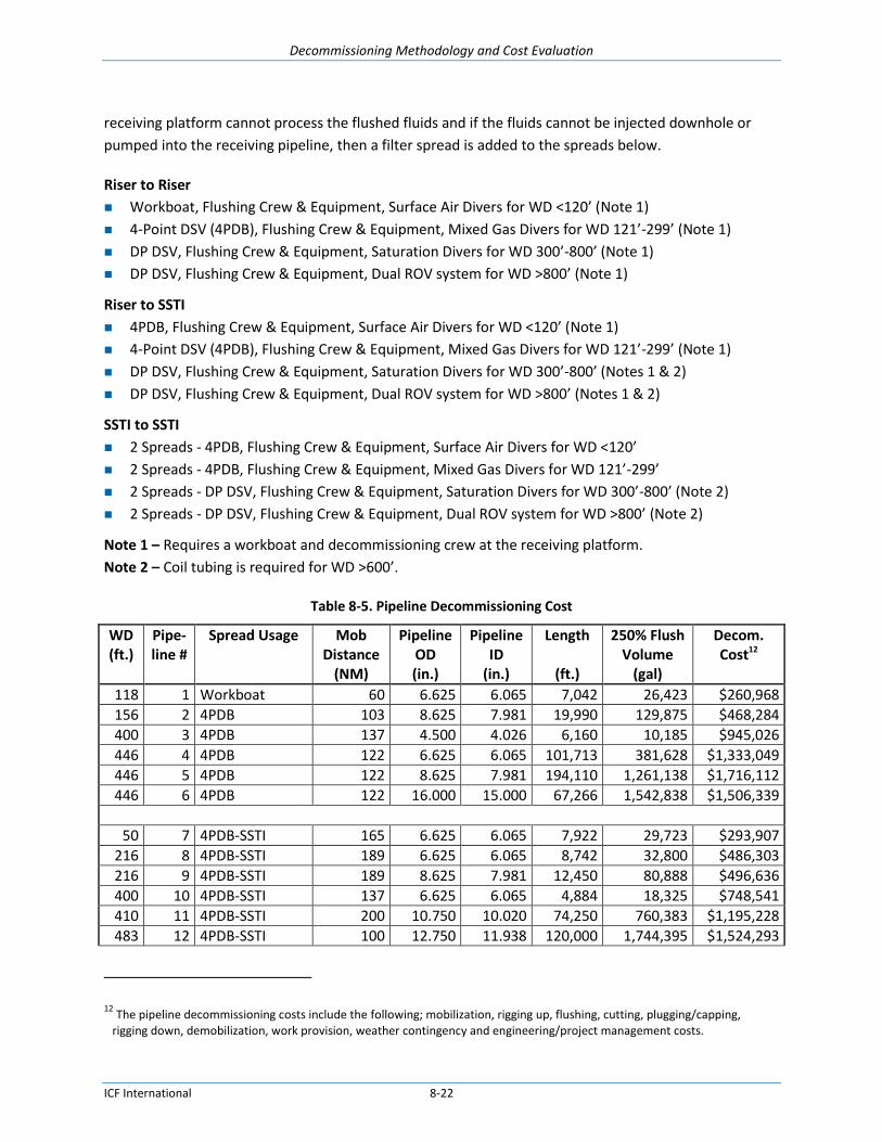
Decommissioning Methodology and Cost Evaluation
ICF International 8-22
receiving platform cannot process the flushed fluids and if the fluids cannot be injected downhole or
pumped into the receiving pipeline, then a filter spread is added to the spreads below.
Riser to Riser
Workboat, Flushing Crew & Equipment, Surface Air Divers for WD <120’ (Note 1)
4-Point DSV (4PDB), Flushing Crew & Equipment, Mixed Gas Divers for WD 121’-299’ (Note 1)
DP DSV, Flushing Crew & Equipment, Saturation Divers for WD 300’-800’ (Note 1)
DP DSV, Flushing Crew & Equipment, Dual ROV system for WD >800’ (Note 1)
Riser to SSTI
4PDB, Flushing Crew & Equipment, Surface Air Divers for WD <120’ (Note 1)
4-Point DSV (4PDB), Flushing Crew & Equipment, Mixed Gas Divers for WD 121’-299’ (Note 1)
DP DSV, Flushing Crew & Equipment, Saturation Divers for WD 300’-800’ (Notes 1 & 2)
DP DSV, Flushing Crew & Equipment, Dual ROV system for WD >800’ (Notes 1 & 2)
SSTI to SSTI
2 Spreads - 4PDB, Flushing Crew & Equipment, Surface Air Divers for WD <120’
2 Spreads - 4PDB, Flushing Crew & Equipment, Mixed Gas Divers for WD 121’-299’
2 Spreads - DP DSV, Flushing Crew & Equipment, Saturation Divers for WD 300’-800’ (Note 2)
2 Spreads - DP DSV, Flushing Crew & Equipment, Dual ROV system for WD >800’ (Note 2)
Note 1 – Requires a workboat and decommissioning crew at the receiving platform.
Note 2 – Coil tubing is required for WD >600’.
Table 8-5. Pipeline Decommissioning Cost
WD (ft.)
Pipe- line #
Spread Usage Mob Distance
(NM)
Pipeline OD (in.)
Pipeline ID
(in.)
Length
(ft.)
250% Flush Volume
(gal)
Decom. Cost12
118 1 Workboat 60 6.625 6.065 7,042 26,423 $260,968
156 2 4PDB 103 8.625 7.981 19,990 129,875 $468,284
400 3 4PDB 137 4.500 4.026 6,160 10,185 $945,026
446 4 4PDB 122 6.625 6.065 101,713 381,628 $1,333,049
446 5 4PDB 122 8.625 7.981 194,110 1,261,138 $1,716,112
446 6 4PDB 122 16.000 15.000 67,266 1,542,838 $1,506,339
50 7 4PDB-SSTI 165 6.625 6.065 7,922 29,723 $293,907
216 8 4PDB-SSTI 189 6.625 6.065 8,742 32,800 $486,303
216 9 4PDB-SSTI 189 8.625 7.981 12,450 80,888 $496,636
400 10 4PDB-SSTI 137 6.625 6.065 4,884 18,325 $748,541
410 11 4PDB-SSTI 200 10.750 10.020 74,250 760,383 $1,195,228
483 12 4PDB-SSTI 100 12.750 11.938 120,000 1,744,395 $1,524,293
12
The pipeline decommissioning costs include the following; mobilization, rigging up, flushing, cutting, plugging/capping, rigging down, demobilization, work provision, weather contingency and engineering/project management costs.

Decommissioning Methodology and Cost Evaluation
ICF International 8-23
WD (ft.)
Pipe- line #
Spread Usage Mob Distance
(NM)
Pipeline OD (in.)
Pipeline ID
(in.)
Length
(ft.)
250% Flush Volume
(gal)
Decom. Cost12
693 13 DPDB 96 12.750 11.938 14,217 206,668 $1,867,472
693 14 DPDB 96 14.000 13.250 13,611 243,738 $1,892,577
622 15 DPDB-SAT-SSTI 75 6.625 6.065 42,375 158,990 $1,592,976
622 16 DPDB-SAT-SSTI 75 10.750 10.020 22,707 232,540 $1,536,291
774 17 DPDB-ROV-SSTI 110 8.625 7.981 66,706 433,390 $846,644
863 18 DPDB-ROV-SSTI 193 12.750 11.938 49,106 713,835 $984,590
1000 19 DSI-SSTI 119 8.625 7.981 36,959 240,123 $1,123,847
1000 20 DSI-SSTI 119 8.625 7.981 17,713 115,083 $1,033,760
1027 21 DSI-SSTI 157 12.750 11.938 39,673 576,710 $1,430,473
8.3.4. Umbilical Decommissioning
For the purpose of this study, it is assumed that all hydraulic umbilicals are flushed of chemicals and
both hydraulic and electrical umbilicals are removed. As in pipeline abandonment, depending on water
depth and umbilical length, different removal spreads can be used. Because the majority of umbilicals in
the GOM will be in deeper water at various lengths, this section focuses on the use of an anchor
handling support vessel (AHSV) and ROV spread.
For each umbilical, first set up on the umbilical. If the umbilical is hydraulic, flush the umbilical to the
host, cut the umbilical, attach to cable spool on AHSV, spool the umbilical, and cut umbilical at the host.
If spool can hold more than one umbilical (dependent on diameter, length, and spool capacity) then set
up on next umbilical; if not, relocate to shore to unspool the umbilical(s). The estimated cost per
umbilical per foot water depth is estimated in Table 8-6 and Figure 8-11.
Table 8-6. Umbilical Removal Costs
Estimated Umbilical Removal Cost per Foot of WD
Umbilical Nautical Mile (NM)
1 2 3 5 10 20
400' WD $13.46 $7.57 $5.60 $4.03 $2.85
1000' WD $17.60 $9.63 $6.98 $4.86 $3.27
2000' WD $11.29 $8.08 $5.52 $3.60 $2.63
4000' WD $9.28 $6.24 $3.96 $2.81
6000' WD $6.96 $4.32 $2.99
8000' WD $7.84 $4.76 $3.22
10000' WD $8.73 $5.20 $3.44
Average $15.53 $9.50 $7.49 $6.31 $3.99 $3.02
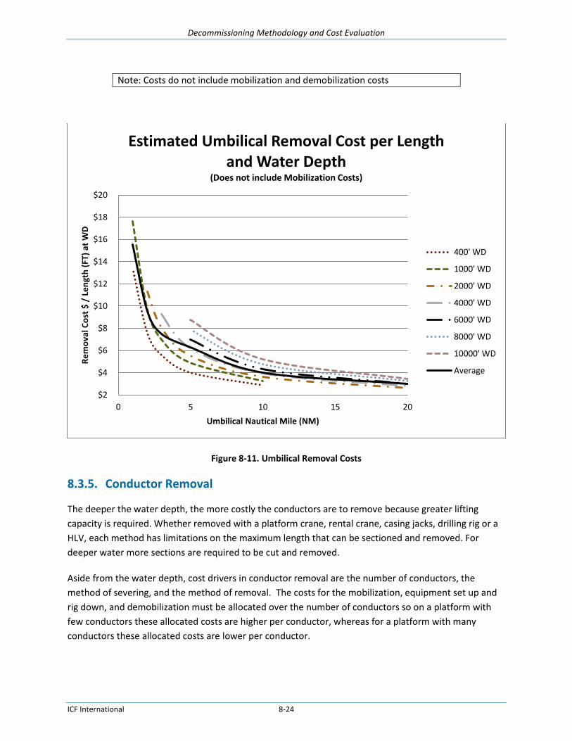
Decommissioning Methodology and Cost Evaluation
ICF International 8-24
Note: Costs do not include mobilization and demobilization costs
Figure 8-11. Umbilical Removal Costs
8.3.5. Conductor Removal
The deeper the water depth, the more costly the conductors are to remove because greater lifting
capacity is required. Whether removed with a platform crane, rental crane, casing jacks, drilling rig or a
HLV, each method has limitations on the maximum length that can be sectioned and removed. For
deeper water more sections are required to be cut and removed.
Aside from the water depth, cost drivers in conductor removal are the number of conductors, the
method of severing, and the method of removal. The costs for the mobilization, equipment set up and
rig down, and demobilization must be allocated over the number of conductors so on a platform with
few conductors these allocated costs are higher per conductor, whereas for a platform with many
conductors these allocated costs are lower per conductor.
$2
$4
$6
$8
$10
$12
$14
$16
$18
$20
0 5 10 15 20
Re
mo
val C
ost
$ /
Le
ngt
h (
FT)
at W
D
Umbilical Nautical Mile (NM)
Estimated Umbilical Removal Cost per Length and Water Depth
(Does not include Mobilization Costs)
400' WD
1000' WD
2000' WD
4000' WD
6000' WD
8000' WD
10000' WD
Average

Decommissioning Methodology and Cost Evaluation
ICF International 8-25
The two most common conductor severing options used in the GOM are explosive severing and abrasive
severing. Several comparisons between explosive and abrasive operations conducted during the
platform removal using a derrick barge are provided in Table 8-7.
Table 8-7. Comparison of Explosive and Abrasive Severing Costs
Explosive Abrasive Difference
Example 1: Platform in 224’ WD with
four 42” diameter piles and four 30”
conductors
Hours to sever 15 38 253%
Total work exposure hours 1865 2081 12%
Total cost $3,408,108 $4,018,630 18%
Example 2:
Total work exposure hours 4251 4494 6%
Total cost $6,062,260 $6,954,753 15%
The table above shows that though the actual duration to sever abrasively is more than double the
duration to sever explosively, the total work exposure hours during the platform removal project using
abrasive severing only increase between 6%-12% than using explosive severing and the overall platform
removal costs using abrasives increase between 15% and 18% over explosives. The severing cost
comparisons were performed during the derrick barge operations with the higher cost of the derrick
barge spread and with the higher lifting capacity of the derrick barge to overcome the possibility of
excessive flaring.
Abrasive severing would be the preferred method to eliminate flaring, but takes longer, thus driving up
costs. Using explosives is generally faster and less expensive, but there is always the possibility that:
the conductors will flare out from the detonation and get stuck when being pulled through the
conductor guides if they are not cut and removed and
the presence of protected marine life may delay the explosive operations, increasing costs as the
HLV stands by.
To minimize these costs, the majority of representative platforms in Table 8-1 were estimated with the
conductors severed abrasively and removed with casing jacks prior to the derrick barge arrival. Though
removal with casing jacks generally takes longer than removal with a derrick barge, the reduction in
work spread costs makes removal with casing jacks more economical. Especially for platforms in deeper
water where typically a larger and more costly derrick barge or heavy lift vessel (HLV) is required. Figure
8-12 shows how conductor removal costs using abrasive severing and casing jacks vary for different
numbers of conductors and different water depths. As shown, the unit cost increases as the water
depth increases and the costs per conductor decrease as the number of conductors increase.

Decommissioning Methodology and Cost Evaluation
ICF International 8-26
Figure 8-12. Total Cost per Conductor for Removal Using Abrasive Severing and Casing Jacks
8.3.6. Platform Decommissioning
8.3.6.1. Fixed Platforms
Current fixed platforms in the GOM are installed in water depths up to about 1,300’, not including
compliant towers. Table 8-8 shows representative fixed platforms that were selected to obtain a range
of estimated costs that may be used to compare the reasonableness of cost estimates for other similar
platforms at similar water depths. For confidentiality, the table does not show the identifying locations
of the platforms. The Pile column describes the type of platform leg, leg pile and or skirt pile
configuration. The most economical heavy lift vessel, Derrick Barge or Semi-Submersible Crane Vessel –
SSCV (see DB column) was selected on the basis of the lifting capacity required for the platform’s
removal using the method listed in the Method column. The deck and jacket weights were either known

Decommissioning Methodology and Cost Evaluation
ICF International 8-27
or else reasonable assumptions were made based on similar platforms in similar water depths from
TSB’s database. The appropriate derrick barge was selected based on the lift weights.
Only the most economical removal method estimated is included for each representative platform. The
three methods of determining decommissioning cost that were found to be most economical were 1)
complete removal in a single lift 2) removal by towing to shallower water (hopping) or 3) jacket
sectioning for larger jackets located in water depths ≥ 700’. In Table 8-8, piles or skirt piles ≤60”
diameters were severed with explosives and piles >60” in diameter were severed abrasively. The costs
do include the cargo barge usage during offloading, but do not include dock charges or crane charges.
Table 8-8 shows there is considerable fluctuation in the leg, pile, and skirt pile configurations in the 500’,
800’, and >1000’ ranges, but the numbers generally increase in proportion to the deeper ranges. The
increase in the water depth and in the number of structural members increases the decommissioning
cost as shown in Figure 8-13, where trend line is for cost without conductors and artificial trendline is for
cost with conductors. The estimated costs shown include platform preparation, deck removal, jacket
removal, and site clearance. Because conductor severing and removal can be a major cost and is
dependent on the number of conductors, water depth and the removal method selected, costs are
shown both with and without conductor removal in Table 8-8 and Figure 8-13.
Table 8-8. Estimated Decommissioning Costs of Representative Fixed Platforms
No. Water Depth
(ft.) Pilesa Derrick
Barge Method
# of Conductors
Cost w/ Conductors
Cost w/o Conductors
1 50 3P DB300 Complete Removal 1 $1,410,391 $1,356,609
2 118 4P DB600 Complete Removal 1 $2,425,276 $2,350,138
3 156 4P DB800 Complete Removal 6 $3,306,325 $2,864,002
4 216 4P DB2K Complete Removal 2 $2,873,582 $2,667,675
5 269 4P DB2K Complete Removal 16 $6,315,020 $4,037,901
6 308 4P DB2K Complete Removal 5 $3,766,927 $3,211,260
7 400 4L-1P-4SP DB4K Complete Removal 6 $7,245,372 $6,325,185
8 410 8P-12SP DB4K Complete Removal 5 $8,215,033 $7,358,113
9 446 4P-4SP DB4K Complete Removal 5 $11,777,547 $10,986,382
10 480 8P-12SP SSCV Complete Removal 18 $15,718,760 $13,237,646
11 483 8P-12SP DB4K Tow to Shallow 19 $32,029,880 $29,483,696
12 484 4P DB2K Tow to Shallow 2 $6,836,169 $6,421,978
13 523 4P-4SP DB2K Tow to Shallow 7 $9,375,800 $8,148,032
14 619 4P-4SP DB4K Tow to Shallow 8 $15,790,690 $14,276,249
15 622 4L-8SP DB4K Tow to Shallow 16 $20,508,850 $18,299,870
16 693 4L-8SP DB4K Jacket Sectioning 3 $15,093,830 $14,370,446
17 774 8P-12SP SSCV Jacket Sectioning 24 $41,194,940 $35,266,998
18 863 8P-12SP SSCV Jacket Sectioning 26 $48,423,520 $42,462,164
19 925 4P-8SP DB4K Jacket Sectioning 14 $23,592,310 $20,030,019
20 935 8P-16SP SSCV Jacket Sectioning 21 $40,385,740 $34,981,872
21 1027 12L-24SP SSCV Jacket Sectioning 62 $76,198,304 $59,277,966

Decommissioning Methodology and Cost Evaluation
ICF International 8-28
No. Water Depth
(ft.) Pilesa Derrick
Barge Method
# of Conductors
Cost w/ Conductors
Cost w/o Conductors
22 1100 6P-24SP SSCV Jacket Sectioning 34 $62,238,048 $53,217,928
23 1300 12L-32SP SSCV Jacket Sectioning 29 $102,992,200 $95,640,620 a Pile Notation: 4L-1P-4SP = 4 leg platform with 1 Center Pile and 4 Skirt Piles 4P-4SP = 4 leg platform with 4 leg piles and 4 Skirt Piles
Figure 8-13. Estimated Platform Decommissioning Costs
Figure 8-14 presents platform cost curves from the data in Table 8-8 for the platforms removed in a
single lift, corresponding to water depths of 50 to 480 feet. Figure 8-15 presents similar curves for
platforms in 483 to 622 feet of water removed by towing to shallower water. Figure 8-16 presents the
estimated cost data for platforms in 693 to 1300 feet of water removed by jacket sectioning.
Platform characteristics and cost data on compliant towers in deeper waters was not available to
develop cost trends for decommissioning these platforms. As an alternative, the trendline for deep
water removals in Figure 8-17 could be used for an initial estimate for platforms requiring an HLV.
$0
$10,000,000
$20,000,000
$30,000,000
$40,000,000
$50,000,000
$60,000,000
$70,000,000
$80,000,000
$90,000,000
0 200 400 600 800 1000 1200 1400
Co
st (
USD
)
Water Depth (ft.)
Cost w/ Conductors
Cost w/o Conductors
Artificial Trend
Trend
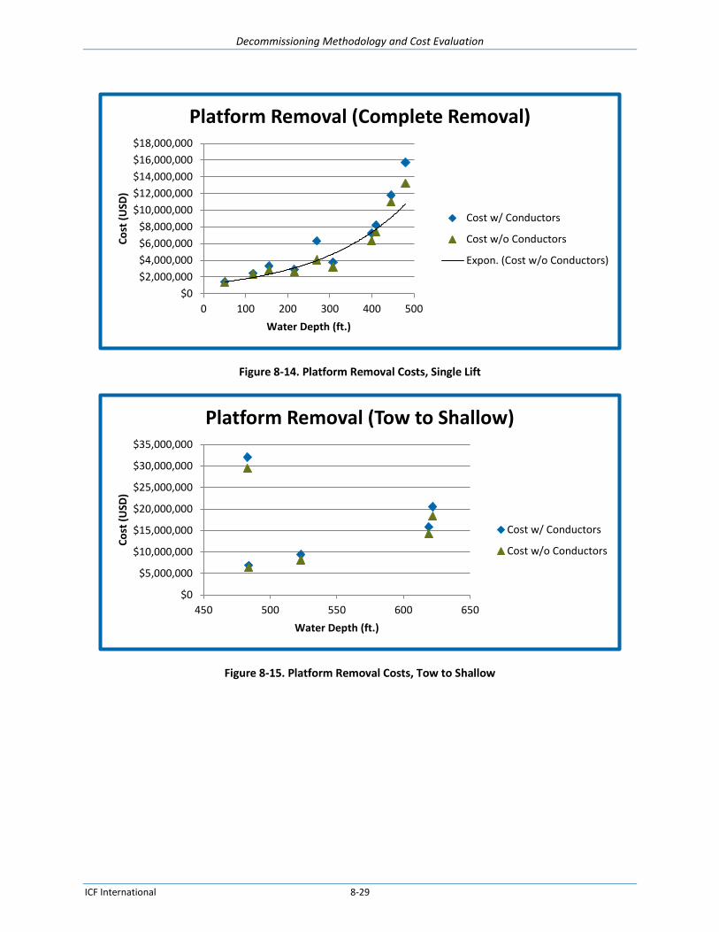
Decommissioning Methodology and Cost Evaluation
ICF International 8-29
Figure 8-14. Platform Removal Costs, Single Lift
Figure 8-15. Platform Removal Costs, Tow to Shallow
$0
$2,000,000
$4,000,000
$6,000,000
$8,000,000
$10,000,000
$12,000,000
$14,000,000
$16,000,000
$18,000,000
0 100 200 300 400 500
Co
st (
USD
)
Water Depth (ft.)
Platform Removal (Complete Removal)
Cost w/ Conductors
Cost w/o Conductors
Expon. (Cost w/o Conductors)
$0
$5,000,000
$10,000,000
$15,000,000
$20,000,000
$25,000,000
$30,000,000
$35,000,000
450 500 550 600 650
Co
st (
USD
)
Water Depth (ft.)
Platform Removal (Tow to Shallow)
Cost w/ Conductors
Cost w/o Conductors
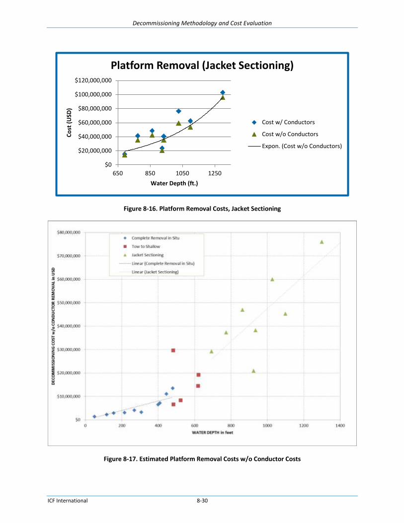
Decommissioning Methodology and Cost Evaluation
ICF International 8-30
Figure 8-16. Platform Removal Costs, Jacket Sectioning
Figure 8-17. Estimated Platform Removal Costs w/o Conductor Costs
$0
$20,000,000
$40,000,000
$60,000,000
$80,000,000
$100,000,000
$120,000,000
650 850 1050 1250
Co
st (
USD
)
Water Depth (ft.)
Platform Removal (Jacket Sectioning)
Cost w/ Conductors
Cost w/o Conductors
Expon. (Cost w/o Conductors)

Decommissioning Methodology and Cost Evaluation
ICF International 8-31
8.3.6.2. Spar Decommissioning Costs
8.3.6.2.1 Preparation Costs
The Spar deck for the estimate below was installed on the hull after hull installation so the cost estimate
is based on the platform preparation and deck removal being done offshore. The cost of platform
preparation depends on the extent of production equipment; whether the facility handles gas, oil or
both; and preparation costs for similar facilities. Spar platform preparation is presented in Table 8-9 and
without further information could be estimated on a deck tonnage basis. With a representative Spar
deck weight of 17,210 st an estimated preparation cost including 8% engineering costs would be
$932,015 or $54.2 per st.
Table 8-9. Spar Platform Removal Preparation
Platform Removal Prep Task Description Hours Days Cost
Flush, Purge and Clean Facilities, Tanks and Vessels 240 10 $266,290
Prepare Modules for Removal 96 4 $106,516
Prepare Mooring Anchors 504 21 $559,209
Spar Platform Removal Preparation Subtotal 840 35 $932,015
8.3.6.2.2 Deck Removal Costs
The primarily cost driver in deck removal is the HLV selected for deck removal and is dependent on the
weight and configuration of the deck. The decommissioning cost using a 5,000 st or less HLV is
estimated at $22.6 MM and where an HLV with capacity greater than 5000 st is needed the
decommissioning cost is estimated at $29.79 MM, as shown in Table 8-10 and Table 8-11.
Table 8-10. Spar Deck Removal using HLV ≤ 5000 st
SPAR Topsides Removal Task Description Hours Days Cost
Cargo Barge Grillage and Tie-down Material 0 0 $400,000
Mobilize SSCV (DP type vessel) 5000 st 24 1.0 $657,504
Set-up DP SSCV vessel 4 0.2 $109,584
Mobilize Cargo Barges for Equipment and Deck 33 1.4 $32,340
Rig & Remove Topside Equipment 180 7.5 $5,107,680
Rig & Remove Deck 360 15.0 $10,215,360
Demobilize Cargo Barges with Equipment and Deck 33 1.4 $32,340
Demobilize SSCV (DP type vessel) 24 1.0 $657,504
Work Contingency
$2,314,894
Weather Downtime
$3,086,525
Spar Topsides Removal Subtotal 658 27.5 $22,613,730
Table 8-11. Spar Deck Removal using HLV > 5000 st
SPAR Topsides Removal Task Description Hours Days Cost
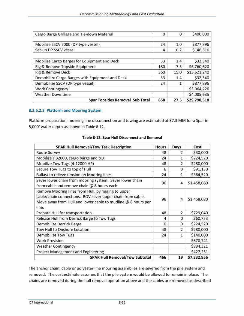
Decommissioning Methodology and Cost Evaluation
ICF International 8-32
Cargo Barge Grillage and Tie-down Material 0 0 $400,000
Mobilize SSCV 7000 (DP type vessel) 24 1.0 $877,896
Set-up DP SSCV vessel 4 0.2 $146,316
Mobilize Cargo Barges for Equipment and Deck 33 1.4 $32,340
Rig & Remove Topside Equipment 180 7.5 $6,760,620
Rig & Remove Deck 360 15.0 $13,521,240
Demobilize Cargo Barges with Equipment and Deck 33 1.4 $32,340
Demobilize SSCV (DP type vessel) 24 1 $877,896
Work Contingency
$3,064,226
Weather Downtime
$4,085,635
Spar Topsides Removal Sub Total 658 27.5 $29,798,510
8.3.6.2.3 Platform and Mooring System
Platform preparation, mooring line disconnection and towing are estimated at $7.3 MM for a Spar in
5,000’ water depth as shown in Table 8-12.
Table 8-12. Spar Hull Disconnect and Removal
SPAR Hull Removal/Tow Task Description Hours Days Cost
Route Survey 48 2 $30,000
Mobilize DB2000, cargo barge and tug 24 1 $224,520
Mobilize Tow Tugs (4-12000 HP) 48 2 $280,000
Secure Tow Tugs to top of Hull 6 0 $91,130
Ballast to relieve tension on Mooring lines 24 1 $364,520
Sever lower chain from mooring system. Sever lower chain from cable and remove chain @ 8 hours each
96 4 $1,458,080
Remove Mooring lines from Hull, by rigging to upper cable/chain connections. ROV sever upper chain from cable. Move away from Hull and lower cable to mudline @ 8 hours per line.
96 4 $1,458,080
Prepare Hull for transportation 48 2 $729,040
Release Hull from Derrick Barge to Tow Tugs 4 0 $60,753
Demobilize Derrick Barge 0 0 $224,520
Tow Hull to Onshore Location 48 2 $280,000
Demobilize Tow Tugs 24 1 $140,000
Work Provision
$670,741
Weather Contingency
$894,321
Project Management and Engineering $427,251
SPAR Hull Removal/Tow Subtotal 466 19 $7,332,956
The anchor chain, cable or polyester line mooring assemblies are severed from the pile system and
removed. The cost estimate assumes that the pile system would be allowed to remain in place. The
chains are removed during the hull removal operation above and the cables are removed as described

Decommissioning Methodology and Cost Evaluation
ICF International 8-33
below. The mooring system estimated in Table 8-12 consists of 12 lines. Since the spool capacity of the
vessel would typically be limited to 2 cables at this depth, the vessel would have to make 6 trips to
transport the 12 cables. Table 8-13 presents additional detail on the costs for mooring cable removal. An
anchor handling vessel with ROV would mobilize and hook up to two mooring cables, reel the cables
onboard, demobilize, and unreel the cables at a shore facility. At a water depth of 5,000 ft, the marginal
cost of severing and removing one mooring line is about $238,000 or a unit cost of about $47 per line
per foot of water depth. This unit cost would be applicable to all SPARs in the GOM.
Table 8-13. Spar Mooring Line Removal
Mooring Line Removal Task Description Hours Days Cost
Mobilize Anchor Handling Supply Vessel (AHSV) 24 1 $98,000
Locate and rig to 2 Mooring Cables 2 0 $8,167
Separate cable from lower chain and spool up cable on AHSV 17 1 $67,559
Demobilize AHSV to Unspooling Site 24 1 $98,000
Unspool Drums 15 1 $59,392
Project Management and Engineering (8%), Work Provision (15%), and Weather Allowance (20%)
$142,381
Spar Mooring Line Removal Subtotal $473,499
8.3.6.3. MTLP & TLP Decommissioning Costs
8.3.6.3.1 Preparation Costs
The cost of platform preparation depends on the extent of production equipment; whether the facility
handles gas, oil or both; and preparation costs for similar facilities. Platform preparation could be
performed near shore or offshore. Data for near shore platform preparation was not available.
Conservatively, offshore costs are included here. TLP platform preparation is presented in Table 8-14
and without further information could be estimated on a cost per deck tonnage basis. Assuming a TLP
deck weight of 8,100 st, the estimated preparation cost including engineering costs would be $812,000
or $100 per st.
Table 8-14. MTLP/TLP Removal Prep
Platform Removal Prep Task Description Hours Days Cost
Flush, Purge and Clean Facilities, Tanks and Vessels 101 4 $123,342
Prepare Modules for Removal 60 3 $73,273
Replace Tension Units for Tendons 504 21 $615,489
Platform Removal Prep Subtotal 665 28 $812,104
8.3.6.3.2 MTLP Deck Removal Costs
MTLPs are assumed to be insufficiently stable to support the deck weight after the mooring system is
severed, therefore MTLP decks are assumed to be removed offshore. The primarily cost driver in deck
removal is the HLV selected for deck removal and is dependent on the weight and configuration of the

Decommissioning Methodology and Cost Evaluation
ICF International 8-34
deck. The decommissioning cost using a 5,000 st or less HLV is estimated at $2.0 MM and whereas the
cost for a >5,000 st HLV is estimated at $3.9 MM, as shown in Table 8-15 and Table 8-16.
TLP’s were assumed stable to support the deck weight after the mooring system is severed, therefore
the TLP decks are assumed to be transported with the hull to a shore facility.
Table 8-15. MTLP Deck <5000 st Deck Removal
MTLP Deck <5000 st Removal Task Description Hours Days Cost
Mobilize Derrick Barge Spread (DB4000 & CB 400) 24 1 $467,240
Rig up to deck 6
$116,810
Sever, Remove Deck & Sea fasten 36 2 $700,860
Demobilize Derrick Barge Spread 24 1 $467,240
Work Contingency 5 $105,129
Weather Downtime 7 $140,172
Platform Removal Subtotal 103 4 $1,997,451
Table 8-16. MTLP Deck >5000 st Deck Removal
MTLP Deck >5000 st Removal Task Description Hours Days Cost
Mobilize Derrick Barge Spread (SSCV 7000 & CB 400) 24 1 $781,640
Rig up to Deck 8
$260,547
Sever, Remove Deck & Seafasten 48 2 $1,563,280
Demobilize Derrick Barge Spread 24 1 $781,640
Work Contingency 7
$234,492
Weather Downtime 10
$312,656
Platform Removal Subtotal 121 5 $3,934,255
8.3.6.3.3 MTLP Platform and Mooring System
Tendon disconnection and removal and deck/hull towing are estimated at $6 MM for a MTLP in 1,700’
of water depth as shown in Table 8-17. The tubular tendon mooring assemblies would be severed from
the pile system and removed. The pile system would be allowed to remain in place for the purpose of
this estimate. The mooring system estimated in Table 8-17 consists of 6 tendons. The cost is broken
down to a hull removal cost of $5.25 MM exclusive of the tendon costs and a tendon severing and
removal cost of $750,210. At 6 tendons, this would generate a severing and removal cost of $125,035
per tendon for this platform or $73 per tendon per foot of water depth. The $73/ft cost would be
applicable to all MTLPs in the GOM. The hulls will be towed to a scrap or refurbishment facility.
Table 8-17. MTLP Tendon & Hull Disconnect and Removal
MTLP Hull Removal/Tow Task Description Hours Days Cost
Route Survey 48 2 $30,000
Mobilize Derrick Barge DB 2000 24 1 $224,520
Mobilize 3 Tow Tugs 24 1 $105,000
Mobilize Cargo Barges 36 2 $141,120
ROV Sever and Remove 3 Tendons From TLP at 400 ft hour 26 1 $375,105

Decommissioning Methodology and Cost Evaluation
ICF International 8-35
MTLP Hull Removal/Tow Task Description Hours Days Cost
and load on Cargo Barge @ 8 hours each
Secure TLP to Derrick Barge 6 0 $88,260
Secure Tow Tugs to TLP 6 0 $88,260
ROV Sever and Remove 3 Tendons From TLP at 400 ft hour and load on Cargo Barge @ 8 hours each 26 1
$375,105
Release TLP to Tow Tugs 4 0 $58,840
Tow TLP to Onshore Location 192 8 $2,824,320
Demobilize Cargo Barge 36 2 $141,120
Demobilize Derrick Barge 24 1 $224,520
Subtotal $4,676,170
Work Contingency (15%) 46 2 $571,484
Weather Downtime (20%) 61 3 $761,978
Platform Removal Subtotal 558 23 $6,009,632
Engineering and Project Management (8%) $480,771
Total $6,490,403
8.3.6.3.4 TLP Platform and Mooring System
Tendon disconnection and removal and deck/hull towing are estimated at $10.4 MM for a TLP in over
3,000 ft of water as shown in Table 8-18. The tubular tendon mooring assemblies would be severed
from the pile system and removed. The pile system would be allowed to remain in place for the
purpose of this estimate. The mooring system estimated in Table 8-18 consists of 12 tendons. The cost
is broken down to a deck/hull removal cost of $4.3 MM exclusive of the tendon costs and a tendon
severing and removal cost of $3.1 MM (before Eng/PM, work provision and weather contingency). At 12
tendons, this would generate a severing and removal cost of $258,693 per tendon for this platform or
$86 per tendon per foot of water depth. The $86/ft cost would be applicable to all TLPs in the GOM.
The hulls will be towed to a scrap or refurbishment facility.
Table 8-18. TLP Tendon & Hull Disconnect and Removal
TLP Hull Removal/Tow Task Description Hours Days Cost
Route Survey 48 2 $30,000
Mobilize Derrick Barge DB 2000 24 1 $224,520
Mobilize 4 Tow Tugs 24 1 $140,000
Mobilize Cargo Barges 36 2 $141,120
ROV Sever and Remove 4 Tendons From TLP at 400 ft hour and load on Cargo Barge @ 16 hours each 64 3 $1,034,773
ROV Sever and Remove 4 Tendons From TLP at 400 ft hour and load on Cargo Barge @ 16 hours each 64 3 $1,034,773
Secure TLP to Derrick Barge 6 0 $97,010
Secure Tow Tugs to TLP 6 0 $97,010
ROV Sever and Remove 4 Tendons From TLP at 400 ft hour and load on Cargo Barge @ 16 hours each 64 3 $1,034,773
Release TLP to Tow Tugs 4 0 $64,673

Decommissioning Methodology and Cost Evaluation
ICF International 8-36
TLP Hull Removal/Tow Task Description Hours Days Cost
Tow TLP to Onshore Location 192 8 $3,104,320
Demobilize Cargo Barge 36 2 $141,120
Demobilize Derrick Barge 24 1 $224,520
Subtotal $7,368,612
Work Provision (15%) 67 3 $970,100
Weather Contingency (20%) 90 4 $1,293,474
Platform Removal Subtotal 749 31 $9,632,186
Engineering and Project Management (8%) $770,575
Total $10,402,761
8.3.6.4. Semi-submersible Decommissioning Costs
8.3.6.4.1 Preparation Costs
Since the deck is an essential part of the structure, platform preparation can be performed dockside or
offshore. To date, these large structures have not been decommissioned and appropriate onshore
preparation costs have not been established. The representative SEMI structure has an estimated
20,000 st deck weight. Using the estimated preparation cost developed for Spar platforms of similar
deck weight deck, a preparation cost of $54.2/st would be appropriate for offshore preparation, or
$1,084,000 for the example 20,000 st deck. Onshore costs should be lower because marine assets would
not be required during preparation operations.
8.3.6.4.2 Platform and Mooring System
Platform preparation, mooring line disconnection and towing are estimated at $6.3 MM for a SEMI in
6000 feet water depth as shown in Table 8-19. The anchor chain / cable or polyester mooring
assemblies would be severed from the pile system and removed and, but for the purpose of this study
the pile system would be allowed to remain in place. (Waiver could applied as directed in 30 CFR
250.1728)
The chains are removed during the hull removal operation and the cables are removed as described
below. The mooring system estimated in Table 8-19 consisted of 16 lines. The cost is broken down to a
hull removal cost of $2.48 MM and a chain mooring line severing and removal cost of $3.8 MM (before
Eng/PM, work provision and weather contingency). At 16 mooring lines, this would generate a severing
cost of $243,013 per mooring line or $40 per line per foot of water depth. This would be applicable to
all SEMIs in the GOM. Costs for the removal of two mooring cables are shown in Table 8-20.
Table 8-19. SEMI Platform Removal
SEMI Removal Task Description Hours Days Cost
Mobilize Tugs (4-12000 HP) 48
$280,000
Prepare facilities for tow. 168 7 $289,107
Mobilize DB2000, cargo barge and tug 24 1 $224,520
Secure Tow Tugs to top of Hull 6 0 $91,130

Decommissioning Methodology and Cost Evaluation
ICF International 8-37
SEMI Removal Task Description Hours Days Cost
Ballast to relieve tension on Mooring lines 24 1 $364,520
Sever lower chain from mooring system. Sever lower chain from cable and remove chain @ 8 hours each 128
$1,944,107
Remove Mooring lines from Hull, by rigging to upper cable/chain connections. ROV sever upper chain from cable. Move away from Hull and lower cable to mudline @ 8 hours per line. 128 5
$1,944,107
Demobilize DB2000, cargo barge and tug 24 1 $224,520
Tow facilities to Ingleside facility 93 4 $542,500
Mothball facilities onshore 168 7 $186,403
Demobilize Tugs 48
$280,000
Platform Removal Prep Subtotal 763 26 $6,370,913
An anchor handling vessel with ROV mobilizes and hooks up to a mooring cable and reels the cable
onboard. If space is available, remove a second cable. Demobilize and unreel the cable(s) at a shore
facility. The process is repeated until all 16 lines are removed for a total cost of $3.88 MM including
Project Management and Engineering of 8%, Work Provision of 15% and Weather Contingency of 20%.
Costs for the removal of two mooring cables are shown in Table 8-20.
Table 8-20. SEMI Mooring Line Removal
Mooring Line Removal Task Description Hours Days Cost
Mobilize Anchor Handling Supply Vessel (AHSV) 24 1 $97,992
Locate and rig to 2 Mooring Cables 2 0 $8,166
Separate cables from lower chains and spool up cables on AHSV 21 1 $84,040
Demobilize AHSV to Unspooling Site 24 1 $97,992
Unspool Drums 19 1 $75,874
Total for 2 Mooring Lines $364,064
Mooring line removal costs for this representative SEMI are estimated to cost $364,064 for two cable
lines or $30 per mooring line per foot of water depth. This cost would be applicable to other SEMIs in
the GOM.
8.3.6.5. FPSO Decommissioning Costs
FPSOs in GOM (i.e. Petrobras at Chinook) are very rare and cost estimates for the removal of these
platforms in the U.S. are not available. Internationally there are many types of FPSO designs with some
permanently secured with multiple mooring lines and some permanently secured to single point
mooring systems that allow the vessels to rotate with environmental conditions. Estimated or actual
decommissioning costs are available for a few FPSOs, but the wide variance makes meaningful
comparisons difficult.

Decommissioning Methodology and Cost Evaluation
ICF International 8-38
An FPSO was decommissioned from offshore Malaysia at an actual cost of $17.2 million, including
removal of the FPSO, mooring chains, and subsea structures as well as capping the pipelines13. The cost
for decommissioning the BW Athena FPSO which operates on the United Kingdom Continental Shelf
(UKCS) is estimated to be $94 million, but the majority of the costs are attributable to well P%A.14 The
estimated costs for the preparation, removal, and disposal of BP’s 154,000 metric ton Schiehallion FPSO
is reported to be $125 million15. Table 8-21 presents actual cost data for the decommissioning of the
Sevan Voyageur FPSO in the UKCS16.
Table 8-21. Shelley FPSO Decommissioning Costs
FPSO Decommissioning Activity Cost (millions)
Remove subsea facilities $12.4
Remove the FPSO $12.7
Plug and abandon wells $23.9
Post-decommissioning surveys $ 0.8
Total $49.8
The mooring lines for an FPSO are removed in the same manner as the SEMI mooring system discussed
above. The cost per mooring line per foot of water depth developed for SEMIs also applies to FPSOs.
8.3.7. Subsea Structure Decommissioning
Decommissioning subsea structures, wells, manifolds, jumpers, etc., involves removing everything to 15
feet below the mudline or leaving selected structures in place. For the purpose of the estimates
presented herein, wells and structures that are stabbed over or attached above anchored templates are
removed, but the anchored templates themselves are allowed to remain in place (waiver could applied
as directed in 30 CFR 250.1728.). Costs for removal of subsea structures with wells are included in the
well P&A operations.
8.3.8. Site Clearance and Verification
Site Clearance costs are primarily a function of mobilization/demobilization distance, water depth,
number of wells, and age of the facility. As each of these parameters increase, site verification and
clearance costs increase. Table 8-22 presents estimated site clearance and verification costs for a
floating platform in 3,000 to 5,000 feet of water. (See 30 CFR 250.1741 & 250.1742)
13
World Oil, “IEV Malaysia completes FPSO decommissioning contract”, 6 May 2014,
http://www.worldoil.com/news/2014/5/6/iev-malaysia-completes-fpso-decommissioning-contract 14
Decomworld, “Updated Athena field decom cost estimates soar 66%, to £60m”, 22 October 2014. http://analysis.decomworld.com/structures-and-maintenance/updated-athena-field-decom-cost-estimates-soar-66-%C2%A360m
15 BP, “Schiehallion & Loyal Decommissioning Programmes Phase 1”, April 2013.
16 Premier Oil, “Shelley Field Decommissioning Programmes, Close Out Report”, November 2012.
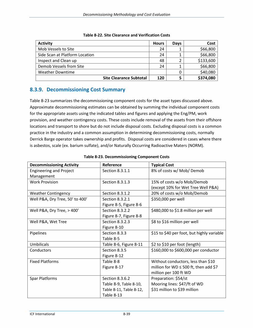
Decommissioning Methodology and Cost Evaluation
ICF International 8-39
Table 8-22. Site Clearance and Verification Costs
Activity Hours Days Cost
Mob Vessels to Site 24 1 $66,800
Side Scan at Platform Location 24 1 $66,800
Inspect and Clean up 48 2 $133,600
Demob Vessels from Site 24 1 $66,800
Weather Downtime
0 $40,080
Site Clearance Subtotal 120 5 $374,080
8.3.9. Decommissioning Cost Summary
Table 8-23 summarizes the decommissioning component costs for the asset types discussed above.
Approximate decommissioning estimates can be obtained by summing the individual component costs
for the appropriate assets using the indicated tables and figures and applying the Eng/PM, work
provision, and weather contingency costs. These costs include removal of the assets from their offshore
locations and transport to shore but do not include disposal costs. Excluding disposal costs is a common
practice in the industry and a common assumption in determining decommissioning costs, normally
Derrick Barge operator takes ownership and profits. Disposal costs are considered in cases where there
is asbestos, scale (ex. barium sulfate), and/or Naturally Occurring Radioactive Maters (NORM).
Table 8-23. Decommissioning Component Costs
Decommissioning Activity Reference Typical Cost
Engineering and Project Management
Section 8.3.1.1 8% of costs w/ Mob/ Demob
Work Provision Section 8.3.1.3 15% of costs w/o Mob/Demob (except 10% for Wet Tree Well P&A)
Weather Contingency Section 8.3.1.2 20% of costs w/o Mob/Demob
Well P&A, Dry Tree, 50’ to 400’ Section 8.3.2.1 Figure 8-5, Figure 8-6
$350,000 per well
Well P&A, Dry Tree, > 400’ Section 8.3.2.2 Figure 8-7, Figure 8-8
$480,000 to $1.8 million per well
Well P&A, Wet Tree Section 8.3.2.3 Figure 8-10
$8 to $16 million per well
Pipelines Section 8.3.3 Table 8-5
$15 to $40 per foot, but highly variable
Umbilicals Table 8-6, Figure 8-11 $2 to $10 per foot (length)
Conductors Section 8.3.5 Figure 8-12
$160,000 to $600,000 per conductor
Fixed Platforms Table 8-8 Figure 8-17
Without conductors, less than $10 million for WD ≤ 500 ft, then add $7 million per 100 ft WD
Spar Platforms Section 8.3.6.2 Table 8-9, Table 8-10, Table 8-11, Table 8-12, Table 8-13
Preparation: $54/st Mooring lines: $47/ft of WD $31 million to $39 million

Decommissioning Methodology and Cost Evaluation
ICF International 8-40
Decommissioning Activity Reference Typical Cost
MTLPs Section 8.3.6.3 Table 8-14, Table 8-15, Table 8-16, Table 8-17
Preparation: $100/st Tendons: $73/ft of WD $9 million to $11 million total
TLPs Section 8.3.6.3 Table 8-14 Table 8-18
Preparation: $100/st Tendons: $86/ft of WD $11 million total
Semi-submersible Platforms Section 8.3.6.4 Table 8-19, Table 8-20
Preparation: $54/st Mooring lines: $40/ft of WD $15 million total
FPSOs Section 8.3.6.5 Insufficient data
Subsea Structures Section 8.3.7 Section 8.3.2.3
See Well P&A, Wet Tree costs
Site Clearance and Verification Section 8.3.8 $400,000, but sensitive to Mob/Demob costs Up to 1% of total costs
8.3.10. Material Disposal
Typically in the GOM, disposal location is usually not considered directly in decommissioning estimates.
The derrick barge contractor usually takes possession of the structure when it is placed on the cargo
barge and realizes any disposal costs or profits from the salvage of material. Therefore, disposal costs
have already been included in the estimates for the removal of the various components. Disposal
practices may vary in other parts of the world. Even though the salvage value or disposal cost is not
borne directly by the platform owner, scrap steel prices affect the bid prices of the decommissioning
contractors.
Estimates should be developed in a manner that satisfies the reporting and audit requirements of
Financial Accounting Standards Board (FASB) Statement of Financial Accounting Standards No. 143,
“Accounting for Asset Retirement” (SFAS 143); i.e., what a willing 3rd party would consider in today’s
costs with no future adjustments. By this standard, scrap credit values must be treated separately from
decommissioning costs. Therefore, any credit for scrap in not included in the decommissioning
estimates. Although there may some value for processing, production and compression equipment, any
revenue from the sale of such is generally ignored.
8.4. Comparisons of Actual and Estimated Decommissioning Costs
This section presents a comparison of actual platform removal cost compared to estimated costs. The
data gathering portion of this study included soliciting decommissioning cost information from BSEE,
industry sources, and foreign government sources; compiling actual decommissioning costs on as many
facilities as feasible within the timeframe of this study; comparing actual decommissioning costs to
estimated decommissioning costs; and calculating actual to estimated cost ratios.

Decommissioning Methodology and Cost Evaluation
ICF International 8-41
Requests for actual decommissioning cost data were sent out globally to over 2,000 oil and gas offshore
operators and service providers. Some operators were also contacted by phone to encourage data
sharing or to follow-up on responses to the electronic requests. Fewer than a dozen operators – all
operating in the Gulf of Mexico - responded that they would be willing to provide actual cost data. Some
of those operators later declined to actually provide any data. However, actual cost data was received
on more than 200 structures. Some of the data included both authorization for expenditure (AFE) costs
and actual costs.
The cost data received varied in its completeness, level of detail, and usefulness. In analyzing the cost
data received, only costs that itemized a breakout of platform, pipeline, and well costs were used. Actual
cost data was compiled for a sampling of over 200 platforms in varying water depths and platform types.
For each of these platforms, estimated costs were generated based on the platform type, water depth
and location. In estimating the decommissioning cost for a particular structure, it is imperative that the
type of platform and its characteristics are known; e.g., 4-pile in 150 water depth in Vermillion block
294. BSEE’s predecessor agency, MMS, often provided that data. It would be very beneficial for BSEE to
obtain and maintain that type of information on all platforms to assist in understanding
decommissioning costs and bonding requirements.
TSB has used a proprietary estimating program Platform Abandonment Estimating System (PAES®) for
over 30 years that tracks thousands of platforms of all types globally, documents the offshore
decommissioning resource costs annually, and documents the estimated decommissioning cost for the
year the estimate was generated. The estimates have been routinely benchmarked against actual
removals in the GOM and adjusted accordingly. The current resource rates or those for any given past
year can be reviewed and used. The basic platform characteristics (example) used to generate platform
estimates using PAES are:
Platform offshore block and identification (e.g., High Island A-477 A) or distance from shore base17
Water depth
Number of legs, piles and or skirt piles
Diameter of piles
Number of conductors (if present)
Overall deck and jacket dimensions
Overall deck and jacket lift weights
Equipment installed on deck after initial deck installation and equipment lift weights
For fixed platforms, disposal location is usually not considered for decommissioning estimates. A
common practice in the GOM is that the derrick barge provider takes possession of the removed
platform, as is where is, upon seafastening to the cargo barge. The provider realizes any profit or loss
between dismantlement and scrap value.
17
Shore base is the location from which resources are mobilization

Decommissioning Methodology and Cost Evaluation
ICF International 8-42
The data received from operators and service providers was evaluated and compared with known data
from the PAES program. Where the above characteristics were provided, cost estimates were developed
for comparison using resource costs for the year of actual decommissioning. Where the characteristics
were not provided with actual costs, the PAES database was researched for available estimates and
where a match was found with the above characteristics an estimate was generated using the resource
costs for the year of decommissioning. Where the year of decommissioning was not provided in the data
received, BSEE records were used to determine the year of decommissioning.
We have compiled actual cost data on 60 decommissioning projects. At many of these platforms,
multiple decommissioning projects were performed. In total, we estimate that we have cost comparison
data on over 200 decommissioned platforms.
The tables below present details on the structures for which we have obtained actual cost data and have
developed estimated decommissioning costs. Note that all of the information pertains to fixed platforms
in the Gulf of Mexico, largely because this is the area where most decommissioning has occurred and
because older structures are primarily fixed platforms. The platform water depths range from 7 to 341
feet.
Table 8-24 lists the 21 structures for which we have the structure pile information in addition to the
structure location, water depth, platform type, and decommissioning cost data. The cost data includes
the estimated cost from TSB’s Platform Abandonment Estimating System (PAES), the operator’s AFE,
and the actual decommissioning cost.
All costs in this section include estimated and actual costs and are based on information, durations and
resource costs available at the time of this study. This study reviewed and applied the significant
amount of technical and cost data compiled from previous studies on platforms for BSEE and from
private companies that have been decommissioning in the Gulf of Mexico. The majority of the cost data
pertains to platforms that were located in water depths of less than 400’. There is less data available on
platforms in water depths greater than 400’ because fewer decommissioning projects have occurred in
those water depths in the Gulf of Mexico and dramatically fewer in other locations around the world.
Due to confidentiality agreements between TSB and operators that provided cost data, the exact
platform locations are not provided. The costs presented below are for the year of decommissioning.
Table 8-24. Fixed Platforms with Actual and Estimated Removal Costs with Pile Information
Location Removal Date Platform
Piles
Water Depth
(ft.)
Platform Abandonment
Estimating System®
Estimated Cost
Approval for Expenditure
Estimate Actual Cost
VR 3/18/2009 4 35 $1,294,593 $1,481,332 $1,414,936
EI 9/12/2011 9 45 $1,440,376 $1,027,508 $3,694,578
EI 5/7/2011 3 49 $1,105,596 $891,840 $676,399
CA 8/28/2008 4 50 $1,534,192 $978,704 $923,257

Decommissioning Methodology and Cost Evaluation
ICF International 8-43
EI 5/10/2011 4 50 $1,120,693 $752,091 $1,001,430
EI 8/5/2007 10 52 $2,026,532 $1,494,047 $3,092,232
EI 8/1/2011 16 52 $2,716,184 $2,654,584 $3,117,237
WC 11/4/2007 1 53 $874,557 $1,270,511 $320,338
BA 10/25/2011 4 81 $3,306,824 $1,287,696 $2,184,761
VR 11/5/2009 8 82 $2,579,279 $2,287,764 $5,759,360
MP 4/25/2011 4 95 $2,566,551 $1,521,017 $3,170,275
EI 9/26/2003 4 98 $738,300 $1,902,000 $1,902,000
ST 7/20/2011 4 147 $2,197,335 $1,532,882 $1,190,175
VR 3/27/2012 4 155 $2,813,159 $2,042,576 $4,742,555
HI-A 10/6/2011 4 191 $3,197,802 $2,559,486 $4,969,896
ST 6/16/2013 4 196 $3,222,619 $1,138,004 $5,451,829
HI-A 10/31/2006 3 217 $1,606,584 $1,438,565 $1,638,946
HI-A 9/3/2013 8 232 $5,465,623 $3,575,188 $6,673,922
MP 7/8/2012 4 269 $6,315,020 $2,881,149 $8,069,728
HI-A 9/5/2013 4 280 $13,254,150 $5,387,879 $14,186,704
EC 6/13/2007 4 308 $3,766,927 $3,758,317 $3,891,030
Table 8-25 presents information on a single decommissioning campaign involving approximately 200
structures at 39 locations. We have both estimated and actual cost data for this campaign, but only in
the form of summary data at each location. For these platforms, we have structure location, water
depth, and platform type, but we do not have detailed information on the number of platforms at each
location or on the number of piles for each platform. However, TSB’s predecessor company managed or
was directly involved in the removal of these platforms and had the specific pile and platform
information when the estimated decommissioning costs were calculated. Therefore the cost information
is relevant for the purposes of the estimated and actual cost comparisons.

Decommissioning Methodology and Cost Evaluation
ICF International 8-44
Table 8-25. Fixed Platforms with Actual and Estimated Removal Costs without Pile Information
Location Removal
Date Water Depth
(ft.)
Platform Abandonment
Estimating System®
Estimated Cost
Actual Cost
SS 1997 7 $9,167,374 $6,775,081
GA 1997 23 $2,454,056 $159,718
VR 1997 40 $1,063,437 $361,384
VR 1997 43 $709,367 $536,394
HI 1997 46 $3,406,672 $2,974,676
HI 1995 46 $947,249 $1,379,979
HI 1997 49 $1,380,827 $1,012,849
SS 2000 52 $3,193,261 $1,042,562
WC 1997 66 $1,554,843 $1,540,755
SM 2002 72 $2,070,926 $1,960,706
SM 2002 72 $523,675 $535,054
SS 2000 72 $1,878,461 $2,296,729
MU 1997 79 $1,753,243 $1,656,759
GA 1998 85 $1,052,252 $482,032
EC 2000 89 $469,196 $994,088
EC 2001 89 $1,072,351 $646,781
SM 2001 95 $1,332,171 $1,356,566
SS 2002 100 $830,196 $571,349
MI 1997 102 $1,309,950 $1,252,699
EC 2001 108 $867,150 $944,626
EC 2000 115 $2,178,958 $309,999
VR 2001 115 $996,444 $1,145,719
MU 1992 118 $1,158,906 $1,673,999
WD 1996 128 $1,261,673 $688,780
EI 1998 161 $709,789 $324,706
HI A 1998 167 $594,094 $873,678
HI A 1995 167 $1,675,823 $1,271,449
WC 1996 187 $601,868 $565,731
WC 2001 190 $2,207,850 $1,175,320
EI 1996 194 $2,173,176 $1,368,956
HI A 1995 194 $552,830 $736,646
EI 2009 197 $2,239,885 $1,959,434
VR 1995 197 $3,331,889 $4,400,349
VR 1998 203 $2,916,729 $2,434,843
HI A 1992 210 $426,996 $690,169
HI A 2001 210 $741,307 $807,111
EI 1995 312 $1,043,207 $2,242,102
VR 1991 340 $1,099,220 $1,766,339
EI 1997 341 $1,932,884 $2,111,971
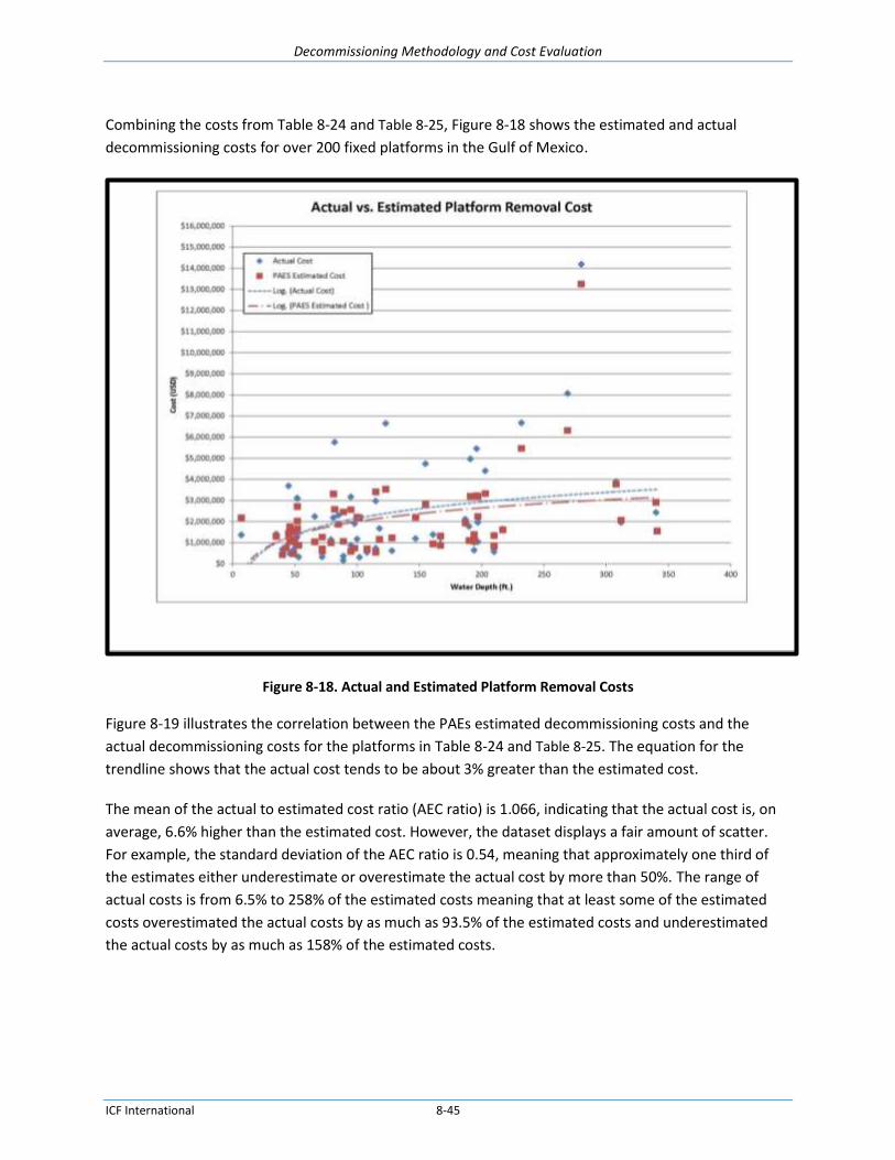
Decommissioning Methodology and Cost Evaluation
ICF International 8-45
Combining the costs from Table 8-24 and Table 8-25, Figure 8-18 shows the estimated and actual
decommissioning costs for over 200 fixed platforms in the Gulf of Mexico.
Figure 8-18. Actual and Estimated Platform Removal Costs
Figure 8-19 illustrates the correlation between the PAEs estimated decommissioning costs and the
actual decommissioning costs for the platforms in Table 8-24 and Table 8-25. The equation for the
trendline shows that the actual cost tends to be about 3% greater than the estimated cost.
The mean of the actual to estimated cost ratio (AEC ratio) is 1.066, indicating that the actual cost is, on
average, 6.6% higher than the estimated cost. However, the dataset displays a fair amount of scatter.
For example, the standard deviation of the AEC ratio is 0.54, meaning that approximately one third of
the estimates either underestimate or overestimate the actual cost by more than 50%. The range of
actual costs is from 6.5% to 258% of the estimated costs meaning that at least some of the estimated
costs overestimated the actual costs by as much as 93.5% of the estimated costs and underestimated
the actual costs by as much as 158% of the estimated costs.

Decommissioning Methodology and Cost Evaluation
ICF International 8-46
Figure 8-19. Actual vs. Estimated Platform Removal Costs
Analyzing the same data in terms of AEC differentials instead of AEC ratios shows the cost difference
between the estimated and actual costs. Specifically, Figure 8-20 shows the dollar amount by which the
actual decommissioning costs exceeded the estimated decommissioning costs for each of the 60 cases in
Table 8-24 and Table 8-25. Note that in nearly every case, the actual cost was no more than about $2
million above the estimated cost.

Decommissioning Methodology and Cost Evaluation
ICF International 8-47
Figure 8-20. Actual Minus Estimated Platform Removal Costs
Decommissioning Methodology and Cost Evaluation
ICF International 9-1
9. Contingencies and Uncertainties Impacting Cost Estimating
9.1. Introduction
All cost estimates for major projects incorporate assumptions that may or may not prove to be accurate
when the work is actually performed. This is true in decommissioning offshore facilities. We distinguish
between contingencies and uncertainties as follows:
Contingencies are defined as cost categories that are reasonably likely or certain to occur but whose
costs may be highly variable or difficult to estimate. Examples of contingencies include project
management, weather impacts, and unforeseen or unknowable decommissioning complications.
Contingency costs can be estimated based on the ranges of similar costs on past projects.
Uncertainties are defined as events or conditions which are possible but which have a low
probability of occurrence. Examples of uncertainties include labor strikes, interference by third
parties, serious environmental or safety incidents, contractor defaults, and loss of key personnel or
major equipment. The potential costs for uncertainties are difficult to quantify because of their low
frequency of occurrence and because of the unknown magnitudes or durations of the triggering
events.
All contingencies and uncertainties that actually occur cause work delays and added costs. The following
sections list specific contingencies commonly used in decommissioning estimates and list a number of
uncertainties that may be experienced. The range of uncertainties is not exhaustive as these are
primarily speculative.
9.2. Contingencies
Contingency costs can be estimated based on predictions of their probability of occurrence and an
analysis of the ranges of similar costs on past projects. The following are examples of contingencies that
are commonly planned for or estimated. Although the estimates or ranges presented below are based
on years of experience and historical price data, in any particular case the contingency costs may exceed
these estimates.
9.2.1. Engineering & Project Management
Every decommissioning project requires a significant amount of engineering analysis and review to plan
how the project can best be accomplished. The amount of engineering labor required depends on many
details of the platform to be decommissioned and on a number of market conditions including the
availability of specialized equipment. The project management costs depend on the size of the overall
decommissioning effort and can vary based on the duration of the project, the size of the labor force,
the number of subcontractors, and other factors. Many of these factors are not well known until the
engineering details of the decommissioning have been determined and even then may change during
decommissioning if complications arise.

Decommissioning Methodology and Cost Evaluation
ICF International 9-2
Engineering & project management (E&PM) costs have been studied by the oil and gas industry. A 2011
review of nearly 50 oil and gas capital projects analyzed the project management costs as a percentage
of the capital expenditures (CAPEX). The values of the projects ranged from about $50 million to over $4
billion, significantly larger than the average decommissioning project. Project management costs were
believed to normally range from 8% to 16% with lower percentages attributed to larger projects.
Although about half of the projects fell within this range, the review found that actual project
management costs ranged from as low as 2% to as high as 26%. Some of the highest percentages were
related to the most expensive projects, not solely with the smaller projects as expected.18
The review concluded that lower project management costs are incurred on projects with which
operators have the most experience, and that costs increase for more novel or more complex projects.
Other factors that contributed to higher project management costs included multiple ownership or
responsibility, poorly developed regional infrastructure, use of innovative technology, and fast-tracking
the project schedule.
In 2013, the Performance Forum prepared an internal study for its oil and gas industry members on the
actual costs of removing steel structures from the North Sea. It found that project management costs
averaged about 8% of the total decommissioning cost. Including the costs for detailed engineering
increased the total E&PM cost to 22%.19
A similar project management cost study reported by TSB in 2014 analyzed the planning, permitting,
engineering and site supervision costs on 55 offshore decommissioning projects performed between
1994 and 2005. The study determined that the median project management cost equaled 8.8% and that
PM costs for over 80% of the projects fell between 4.5% and 15%. These costs did not include any
overhead or supervision costs incurred by the owner or operator.20
For offshore decommissioning, an average of 8% of total project cost has been historically used to
estimate E&PM costs in the GOM. Although these costs are at the low end of the ranges discussed
above, they reflect the fact that most of the decommissioning work in the GOM has been performed on
similar structures, e.g. caissons and steel jacket platforms, in relatively shallow waters (< 400 ft). This has
allowed the decommissioning industry to become increasingly efficient in designing and managing these
decommissioning projects. As decommissioning work extends out into deeper waters and involves less
common structures (TLPs, FPSOs, SEMIs, etc.) or for decommissioning work in other areas around the
globe that present additional logistical challenges, the E&PM costs would be expected to increase.
18
Jamieson, Aileen, “Analysing project management costs”, Turner & Townsend, 2011.
http://www.turnerandtownsend.com/889/_11364.html 19
Jamieson, Aileen, “The cost of decommissioning North Sea platform”, Offshore Technology International, 2013.
http://www.offshore-publication.com/technology/1036-decommissioning-north-sea-platforms-329408234 20
Byrd, Dr. Robert C., Miller, Donald J., and Wiese, Steven M., “Cost Estimating for Offshore Oil & Gas Facility Decommissioning”, 2014 AACE® International Technical Paper, 2014.

Decommissioning Methodology and Cost Evaluation
ICF International 9-3
Regardless of the project, there are certain E&PM functions that must be performed. A small project like
a caisson removal would tend to have lower E&PM costs than the average but it would be a higher
percentage of the total cost. The reverse is true, for larger projects like removing an 8-pile structure in
deep water or removing multiple structures, pipelines or wells, the E&PM costs would be higher but the
percentage of the total would tend to be lower than the average, provided that the project did not
present unusual novelty or complexity. The remoteness of a project impacts the E&PM costs as well. A
long term project in a remote location requires a higher cost for placement of resources on location and
for travel costs. In these cases, a higher E&PM contingency should be applied.
9.2.2. Weather Allowance
Weather can have an important influence on offshore operations but the weather that will occur during
a planned decommissioning schedule cannot be forecast with certainty. However, the statistical
frequency of weather events that would impact decommissioning costs can be determined. A weather
allowance percentage is included in decommissioning cost estimates to compensate for delays caused
by regular weather and for tropical storms.
For estimating offshore decommissioning work, a weather allowance of 20% is typically included,
consisting of 14% for regular weather delays and 6% for delays from named tropical storms. These
percentages were developed based on project weather delays that have been tracked and documented
in the GOM.
Careful planning and timing for short projects like caissons or single platforms might reduce weather
delays, especially as long range weather forecasts improve, but operators have testified before FERC
that they cannot realistically plan around the weather for the decommissioning of multiple structures,
pipelines or numerous wells. Operators usually request decommissioning estimates or asset retirement
obligations (AROs) for their entire offshore inventory or for an entire region and a standard 20%
weather allowance is used in the estimates. Outside of the hurricane season, regular weather would be
anticipated. Pipeline abandonment is dependent on divers and smaller vessels, such as workboats and
4-point diving vessels which are more weather impacted than DP vessels. DP and intervention vessels
with heave-compensated cranes can weather greater seastates than smaller vessels. Liftboats can
jackup and thereby continue working in greater seastates, but only to the extent that the servicing
vessels can operate and supply needed material. Projects on a platform structure such as well P&A and
platform preparation are not directly impacted by regular weather, but the weather may impact
workboats servicing the project.
In areas with seasonal weather fluctuations, such as hurricane season in the Gulf of Mexico, winter
offshore of Alaska, or the monsoon season in Thailand, scheduling decommissioning work during
seasons with more favorable weather may reduce delays and related costs. In areas where seasonal
marine migration occurs, additional planning is required to mitigate potential impacts to the marine
population.

Decommissioning Methodology and Cost Evaluation
ICF International 9-4
Sea currents impact working conditions for all operations where vessels, divers or ROVs are used. For
example, the Cook Inlet in Alaska has large tidal movements that impact the ability to stay on-station
and dramatically raise and lower the waterline. Off the west coast of India, strong currents restrict
diving operations to short work windows. Estimates need to factor in the additional time required to
complete operations under these local conditions.
Weather contingencies can be estimated for other regions that have sufficient meteorological and
oceanographic (metocean) data if the operational constraints of the planned resources are clearly
defined. Metocean data includes weather information (prevailing winds, gust speeds, and storm
information), sea state (swell, wave height, and wave frequency), tides, and currents. Comparing the
operational limitations for a vessel (heave, wind speed for lifting operations) to the historical data, the
weather contingency percentage can be estimated as the amount of time operations cannot be
performed divided by the planned work time in the absence of weather delays. This can be a time and
labor intensive process that depends on the availability of accurate metocean information and
equipment operational constraints and requires a breakdown of each activity. The weather allowance
contingency could vary significantly depending on a company’s risk tolerance and operational practices.
9.2.3. Work Contingencies
Work Contingencies include extra costs from possible delays or deviations from the expected scope of
work due to lack of information and may be added to an estimate when there is uncertainty in the work
scope. Note that a Work Contingency differs from the Work Provision in that Work Provision is not extra
work, but includes all of the minor activities necessary for actual removals that are not currently
itemized in the major task estimates.
It is not uncommon to have incomplete information at the time of decommissioning. Any percentage
applied for work contingencies is determined based on the quality and completeness of the information
and how well defined the decommissioning operations are. The work contingency should be estimated
separately by class of operations and is based on the potential for problems in areas where there are
data gaps. For example, if the current condition of wells scheduled for P&A is not known, a work
contingency may be added to allow for delays caused by problem wells.
The work contingency for a platform well P&A would be different than removing a deep water jacket by
jacket sectioning. The range of values used is normally between 10% and 20%. Higher work contingency
would be added for less defined operations.
The following examples describe work contingencies above and beyond the normal estimated costs if
the conditions were not known and planned for in advance.
On platform jackets with skirt piles, the annulus between the pile and skirt are sometime grouted.
In preparation for severing the piles, there have been occasions where undocumented cement plugs
have been found inside the pile. This prevents the placement of jetting or cutting tools inside the

Decommissioning Methodology and Cost Evaluation
ICF International 9-5
pile. The soil around the pile would need to be jetted or excavated down to the severing depth for
placement of external severing equipment.
The discovery of mudplugs within piles in locations or blocks where other decommissioned
platforms infrequently have mudplugs would require the mudplugs to be jetted out for placement
of the severing tool. Operators may not want to incur the cost to send a crew out in advance to
sound the piles for these plugs, so the cost estimate should include a work contingency.
In pipeline abandonment, the pipelines are cleaned of hydrocarbons. The preferred method is
flushing with sea water 2 ½ times the volume or until a sheen test does not show any hydrocarbons.
Pipeline operators request waivers to use this method and request estimates using this method. If
operators must use pigging methods there may be the risk of interference from paraffin, sand in the
line, unknown pipe damage that may hinder pigging, or unknown valve conditions or flow direction.
Well abandonment is often performed without the latest well information and sometimes even the
latest information is not correct. Extra work not planned could be due to stuck valves, collapsed
casing, or dropped objects in the wellbore needing coil tubing or a drilling rig to resolve.
Subsea well abandonment exposes the decommissioning process to additional risk due to the
complex nature of subsea operations. The amount of any work contingency included would depend
on perceived accuracy of the information.
9.3. Uncertainties
Because of their low frequency of occurrence, the potential costs and the probability of uncertainties is
much harder to predict. Delays and costs for some uncertainties can be estimated, but because of the
low probability of occurrence, the costs are not normally included in a decommissioning estimate.
The following are examples of uncertainties that may arise during a decommissioning project and
impact the project cost and schedule.
Delays caused by Injury or death can be caused by personnel or equipment. This can cause delays of
several days or longer depending on the investigation and any regulatory, law enforcement, or legal
issues.
Work stoppage caused by platform damage by marine vessels. For example, platforms have been
damaged by tankers blown off course during storms. This causes additional delays and costs due to
investigations, additional engineering planning, and repairs so that decommissioning can safely
proceed.
Delays and costs for standby due to labor force or equipment not arriving on time. This is usually a
day or less, but can be longer.
Damage to specialized equipment
Service providers failing to complete contracted work or going out of business. New providers
would need to be vetted, contracts signed, and schedules revised.
Labor unrest or shortage. For example, a labor strike disrupted offshore operations in Norway in
June2015.
Piracy events on a platform or against a vessel will cause cessation of operations pending
government response.

Decommissioning Methodology and Cost Evaluation
ICF International 9-6
Blockage of work by environmental organizations
Loss of key personnel due to personal emergencies, requiring either replacement personnel or
rescheduling part the work
Equipment malfunction or breakdown, requiring assessment to determine cause, repairing the
equipment or mobilizing replacement equipment (if available). If replaced, the productivity of the
replacement equipment may differ from the original.
Disruption to onshore labor force, equipment, suppliers, or materials due to violence, riots, severe
weather, or other causes
Extreme events can occur, such as the severe civil unrest seen during the Arab Spring in Egypt in
January and February 2011.

Decommissioning Methodology and Cost Evaluation
ICF International 10-1
10. Non-technical Impacts on Decommissioning Costs
10.1. Introduction
This section discusses other considerations that affect decommissioning costs and that incorporate the
professional judgment, industry experience, and institutional knowledge that shape decommissioning
decisions. These considerations are less about hard data, which has been included elsewhere, and more
about recognizing the demand trends, regional differences, market conditions, and technological
innovations that affect how decommissioning is performed and how those trends, differences, and
innovations impact decommissioning costs.
10.2. Inflation Impacts
Historically, many of the individual decommissioning costs roughly track the U.S. Consumer Price Index
(CPI). Figure 10-1 compares the increase in rates for commonly used decommissioning vessels to the
increase in the CPI since 1996. Although the trends of most of the rates parallel the trend of the CPI
curve, a few outliers are apparent. For example, the demand for lift boats increased dramatically in 2005
following tropical storm and hurricane damage in the Gulf of Mexico.
Figure 10-1. Offshore Vessel Prices Normalized to 1996
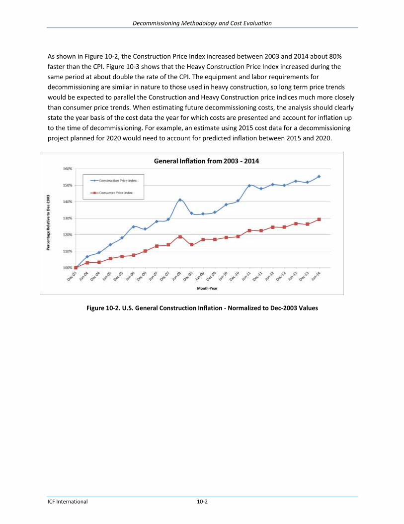
Decommissioning Methodology and Cost Evaluation
ICF International 10-2
As shown in Figure 10-2, the Construction Price Index increased between 2003 and 2014 about 80%
faster than the CPI. Figure 10-3 shows that the Heavy Construction Price Index increased during the
same period at about double the rate of the CPI. The equipment and labor requirements for
decommissioning are similar in nature to those used in heavy construction, so long term price trends
would be expected to parallel the Construction and Heavy Construction price indices much more closely
than consumer price trends. When estimating future decommissioning costs, the analysis should clearly
state the year basis of the cost data the year for which costs are presented and account for inflation up
to the time of decommissioning. For example, an estimate using 2015 cost data for a decommissioning
project planned for 2020 would need to account for predicted inflation between 2015 and 2020.
Figure 10-2. U.S. General Construction Inflation - Normalized to Dec-2003 Values

Decommissioning Methodology and Cost Evaluation
ICF International 10-3
Figure 10-3. Heavy Construction Inflation from 2003 to 2014 - Normalized to Dec-2003
10.3. Demand Impacts
Decommissioning activity has been increasing in the Gulf of Mexico due to aging assets, declining
production, and changes in federal regulations. The issuance of the “Idle Iron” Notice to Lessees (NTL
No. 2010-G05) puts strict time limits on the decommissioning of idled offshore oil and gas assets in the
Gulf of Mexico and is expected to accelerate the decommissioning of some structures. Sustained low oil
and gas prices may further accelerate decommissioning activity as more facilities become uneconomical,
although a decrease in oil prices may not be a dominant factor in determining when decommissioning
occurs. Increased demand for decommissioning services may put upward pressure on decommissioning
costs.
The international oil and gas industry is maturing and moving toward development of more robust
offshore decommissioning regulations. Except in the North Sea, little decommissioning activity has
occurred outside of U.S. waters. This will change as more countries adopt detailed regulations and
offshore assets near end of life. Norway plans to issue risk based guidelines for well P&A in the second
half of 2015. Thailand has issued proposed regulations and is signaling that operators will need to
provide decommissioning plans and schedules in the near future. Increased demand for global
decommissioning services in maturing offshore markets portends upward price pressures worldwide.
Local weather can impact demand as well. Hurricane and tropical storm damage to platforms in the Gulf
of Mexico greatly increased the demand for decommissioning resources due to downed and damaged
platforms. Figure 10-4 shows the increase in the number of platforms removed following the Hurricanes
Katrina, Rita, and Ike.

Decommissioning Methodology and Cost Evaluation
ICF International 10-4
Figure 10-4. Platform Installations and Removals after Major Storms
10.4. Regional Impacts
Regional differences impact many aspects of offshore decommissioning, including the selection of the
best decommissioning technique, the equipment used, and of course decommissioning costs.
10.4.1. Development
A region with a long history of offshore oil and gas development is more likely to have platforms which
have exceeded their useful life and have already been decommissioned, leading to the development of
companies and personnel with decommissioning experience. The reverse is also true, especially in
global regions that do not have decommissioning regulations specifying when platforms are to be
removed. As the decommissioning industry grows in a given region, procedural efficiencies and
competition help to control costs. In contrast, a region that is just beginning to decommission
production assets may face the need to import equipment and expertise, may need to develop support
facilities, would need to develop and train a decommissioning labor force, and therefore would be likely
to face higher initial decommissioning costs.

Decommissioning Methodology and Cost Evaluation
ICF International 10-5
10.4.2. Resource Availability
The regional availability of vessels, equipment, and scrap facilities that support decommissioning
operations also impacts the selection of decommissioning techniques and equipment and therefore
impacts costs. In the 2014 BSEE report Decommissioning Cost Update for the Pacific OCS Region
Facilities, the Mobilization & Demobilization of Derrick Barge costs account for 8% of the total costs. The
available resources on the Pacific coast were limited to a DB500 without accommodation. That resource
was used for dredging and had little experience in decommissioning. The other resources in the region
were in use for marine construction, and the lack of decommissioning experience is a concern for
planning operations. The 2014 Pacific report shows the Mob/Demob costs of derrick barges to range
from $3.1 MM to $7.4 MM per platform based on 23 platforms analyzed (see Table 10-1). The long
mobilization time (100 days) greatly increases the overall cost for the DB for a project that requires the
derrick barge on location for 30 to 80 days. This cost is significant when compared to the Mob/Demob
cost in the Gulf of Mexico of $ 0.4 MM to $ 1.3 MM based on 23 platforms (see Table 10-2).
Regions new to decommissioning operations need to mobilize equipment to the location. Depending on
the distance from the location to the nearest region with assets to perform the work, the mobilization
costs could become a significant portion of the total decommissioning costs. In remote areas or in areas
where decommissioning is relatively new, bringing in decommissioning personnel from outside the area
increases labor costs.
Table 10-1. Estimated Derrick Barge Mob/Demob Costs, Pacific OCS
Project DB Lift
Capability Mob/Demob Cost Calculation
Cost Per Platform
Project I 500 ton $ 165,000 x 100 days x 90% / 2 platforms $7,425,000
Project II 2,000 ton $ 209,000 x 100 days x 90% / 4 platforms $4,702,500
Project III 2,000 ton $ 209,000 x 100 days x 90% / 5 platforms $3,762,000
Project IV 2,000 ton $ 209,000 x 100 days x 90% / 3 platforms $6,270,000
Project V 2,000 ton $209,000 x 100 days x 90% / 6 platforms $3,135,000
Project VI 2,000 ton $209,000 x 100 days x 90% / 3 platforms $6,270,000
Note: From BSEE report, “Decommissioning Cost Update for Pacific OCS Region Facilities”, 2014.

Decommissioning Methodology and Cost Evaluation
ICF International 10-6
Table 10-2. Estimated Derrick Barge Mob/Demob Costs, GOM OCS
10.4.3. Decommissioning Approach
Different countries follow different decommissioning approaches because of differences in the types of
offshore structures, regulatory requirements, economics, or other regional factors. Table 10-3 presents
a sample of decommissioning approaches outside of the Gulf of Mexico.
Table 10-3. Decommissioning Approaches around the World
Gulf of Thailand Platform Removal Technique Planning No decommissioning has occurred, only planning.
Techniques Description
Deck Removal Some decks larger than in the GOM have been installed that were larger than the HLV capacity. A float-over technique was used, were the deck is carried on a submersible vessel. The vessel is specifically designed to fit around the jacket. It positions the deck over the jacket, ballasts down and installs the deck. Reverse installation will likely be the decommissioning technique.
ICF Ref. # Name Piles DB Size Mob (USD) Demob (USD) Total (USD)
1 HI-156-A 3 300 $263,020.16 $263,020.16 $526,040.32
2 EC-220 4 600/800 $203,400.90 $203,400.90 $406,801.80
3 WD-97-A 4 600/800 $277,299.70 $277,299.70 $554,599.40
4 HI-A538-A 4 2000 $492,520.00 $492,520.00 $985,040.00
5 MP-223-A 4 2000 $498,788.20 $498,788.20 $997,576.40
6 EC-353-A 4 2000 $392,291.68 $392,291.68 $784,583.36
7 SP-49-C 4 4000 $445,870.15 $445,870.15 $891,740.30
8 HI-A389-A 8 4000 $653,539.13 $653,539.13 $1,307,078.26
9 EC-381-A 4 4000 $389,225.10 $389,225.10 $778,450.20
10 MC-20-A 8 2000 $622,513.79 $622,513.79 $1,245,027.58
11 EW-826-A 8 4000 $327,624.55 $327,624.55 $655,249.10
12 WC-661-A 4 2000 $453,096.60 $453,096.60 $906,193.20
13 SM-205-B 4 2000 $622,513.79 $622,513.79 $1,245,027.58
14 MC-365-A 4 4000 $359,425.45 $359,425.45 $718,850.90
15 GC-6-A 8 4000 $247,450.45 $247,450.45 $494,900.90
16 GB-172-B 4 4000 $274,611.30 $274,611.30 $549,222.60
17 EW-873-A 8 4000 $314,671.30 $314,671.30 $629,342.60
18 EB-165-A 8 4000 $517,975.80 $517,975.80 $1,035,951.60
19 EB-159-A 4 4000 $598,095.80 $598,095.80 $1,196,191.60
20 EB-160-A 8 4000 $517,975.80 $517,975.80 $1,035,951.60
21 MC-194-A 12 4000 $449,272.90 $449,272.90 $898,545.80
22 MC-109-A 6 4000 $400,600.00 $400,600.00 $801,200.00
23 GC-65-A 12 4000 $286,228.70 $286,228.70 $572,457.40

Decommissioning Methodology and Cost Evaluation
ICF International 10-7
Alaska State Waters and Offshore Sakhalin Islands Platform Removal Technique Planning No decommissioning has occurred, only planning.
Techniques Description
Jacket Removal The jackets are heavy concrete gravity based structures. Planning has considered using massive diamond wire spreads to cut the jacket into sections for removal by a HLV.
United Arab Emirates Platform Removal Technique Planning No decommissioning has occurred, only planning.
Techniques Description
Complete Removal Large gravity based hydrocarbon structures have been installed, resembling an upside down champagne glass with an open bottom. The hydrocarbons float on a water column inside the vessel. Planning considers pumping and cleaning the hydrocarbons from the vessel and then cutting the vessel into sections for removal. Information has been provided by BSEE that the UAE may consider leaving large structures in place. At the time of this study, this has not been confirmed.
Trinidad Platform Removal Technique Planning No decommissioning has occurred, only planning.
Techniques Description
Deck Decommissioning
Planning considers removing the deck and reefing both the deck and jacket.
Some areas of South America and the Caspian Sea Techniques Description
Platform Decommissioning
Structures have been left to decay in place.
Offshore Japan Platform Decommissioning Technique
Techniques Description
Platform Decommissioning
Structures have been reefed offshore of Japan.
10.4.4. Working Conditions
Regional differences in weather, sea states, and distances from shoreline facilities can also affect
decommissioning costs. Harsh weather environments like the Cook Inlet Alaska or offshore Sakhalin
Islands may reduce productivity or impose restrictions on the seasonal working window for
decommissioning activities, both of which contribute to higher costs. Offshore facilities designed for
regions with heavier seas may require more robust, heavier structures which are more costly to remove
than structures designed for calmer or more sheltered locations.
10.5. Market Condition Impacts
Market conditions impact decommissioning costs in several ways. As mentioned above, sustained low
oil and gas prices may render facilities uneconomical for continued operation, leading to them being

Decommissioning Methodology and Cost Evaluation
ICF International 10-8
idled and decommissioned earlier. If such market conditions affect a large number of assets in a region,
the demand and costs for decommissioning services will rise. However, short term decreases in oil
prices would not be expected to be significant in determining decommissioning time.
Conversely, forecasts of higher oil and gas prices that lead to extended operating lives of existing
production assets can also increase the demand for new offshore development. Increased development
can cause competition for equipment with limited availability such as heavy lift vessels which are
needed both for construction and decommissioning.
Some of the same vessels and equipment used for decommissioning are used by other sectors of oil and
gas industry. An increase in oil and gas prices could lead to higher exploration and development
activities, which could cause increased demand and supply constraints.
Federal regulations require that operators get approval from the BSEE District Manager before
decommissioning wells and from the BSEE Regional Supervisor before decommissioning platforms,
pipelines, or other facilities. Regulations also have a conservation component where BSEE makes a
determination whether or not the oil company could continue to produce economically.
Disruptions, contraction, or excessive demand at ancillary facilities support industries could impact
decommissioning costs. For example, a natural disaster or high steel scrap prices could overwhelm the
recycling capabilities of regional scrap yards. This type of disruption could impact decommissioning costs
positively or negatively.
10.6. Technology Impacts
New technologies are constantly being developed to make offshore operations faster, cheaper, safer or
even possible, as in the case of technologies for ever deeper water. New state-of-the-art technology is
often initially costly, but ultimately new technologies tend to drive down costs or else they would not be
accepted by the industry. One example is the conversion of jack-up drilling rigs to MOPU. They are less
expensive than fixed or floating platforms, require less lead time, and can be decommissioned by jacking
down and leaving the location.
In some cases, lack of suitable, cost effective technology drives decommissioning decisions. For
example, the absence of any current technology to completely remove the large concrete gravity
structures such as Condeep in the Norwegian sector of the North Sea within acceptable safety and
technical risk criteria is a major reason that derogation of these structures is allowed. In addition, the
costs of complete removal would be prohibitive.
Technological changes may have dramatic impacts on future decommissioning costs. Floating
production systems and subsea systems eliminate much or all of the platform jacket structure and have
radically different decommissioning requirements.

Decommissioning Methodology and Cost Evaluation
ICF International 10-9
10.7. Regulatory Impacts
Regulations can either increase or decrease decommissioning costs. As noted above, regulations such as
the “Idle Iron” NTL can increase decommissioning demand and costs while derogation of removal
requirements for concrete structures in the UK and Norway in the North Sea can greatly reduce
decommissioning costs. In some less-developed regions, idle steel jackets are simply abandoned in
place. Regulations which require a higher degree of safety or stricter environmental compliance may
impose higher direct costs on the decommissioning industry but greatly reduce the indirect costs
associated with worker injuries and deaths and the costs associated with recovering from environmental
lapses. Chapter 11 discusses regulatory differences in greater detail.
10.8. Other Possible Impacts
There are many other non-technical factors that can potentially impact decommissioning costs, but not
all of them will be addressed in this study.
The following conditions may have an impact on decommissioning costs but are considered beyond the
scope of the present study and will not be analyzed in the final report.
Changing weather patterns or climate change leading to more storms, rising sea levels, or increased
storm intensity
Political trends such as armed conflict or nationalization of private assets in foreign countries
Competition for resources such as from other offshore developments like wind farms
Long term shifts in energy patterns such as a shift to a hydrogen economy, increased production of
onshore natural gas from hydraulic fracturing, or reduced demand for fossil fuels due to widespread
adoption of electric vehicles or increased renewable energy production
New large onshore or offshore discoveries
Government permission for access to more areas (ex. Pacific and Atlantic OCS.)
Development of alternate forms of fossil energy such as gas hydrates, unconventional coal bed
methane, or liquefied coal
Increased demand for alternative uses for offshore facilities, e.g., adding wind turbines to facilities,
or utilizing platforms and wells for CO2 injection as part of a carbon capture and storage strategy
Change in policies for artificial reef programs or reefing of semi-submersibles
Change in federal regulations related to crude export
Major natural disasters such as earthquakes (west coast) and hurricanes
Decommissioning Methodology and Cost Evaluation
ICF International 11-1
11. Safety and Environmental Accidents, Incidents and Events
11.1. Introduction
ICF performed a search of industry reports and government databases to identify safety and
environmental accidents, incidents, or events that occurred during facility decommissioning operations.
ICF also reached out directly to government agencies to obtain additional relevant data. The main
objective was to determine which decommissioning techniques are associated with the most frequent
or the most serious types of accidents, injury, or event to develop a relative risk ranking.
Decommissioning incidents were not found to be classified separately from other offshore oil and gas
related accidents, therefore this report also provides statistics for all offshore oil and gas activities.
Decommissioning data is reported when it was identified and compared to overall offshore oil and gas
statistics to identify any trends.
11.2. Data Sources
The primary data source for incidents in the United States was a data set provided by BSEE documenting
decommissioning related events based on a keyword search of the Technical Information Management
System (TIMS). The search yielded fewer than 350 individual records of identifiable decommissioning-
related safety and environmental incidents over an eleven year period.
International organizations, such as the International Association of Oil & Gas Producers (IOGP) and the
International Association of Drilling Contractors (IADC) also provided incident statistics. The primary
sources for the international data in this report were the IOGP and the IADC datasets. Individual
countries also track their incident statistics; however they showed the same trends as the worldwide
statistics provided by the IOGP and the IADC and were omitted from the analysis to avoid repetition.
The International Regulators’ Forum (IRF) comprises national regulatory agencies in 10 countries
associated with health and safety in offshore upstream oil and gas activities. BSEE represents the IRF in
the U.S. IRF member agencies in Australia, Brazil, Canada, Denmark, Mexico, the Netherlands, New
Zealand, Norway, and the United Kingdom were contacted in order to identify additional data sources..
Responses were received from Australia, Brazil, Canada, Denmark, New Zealand, Norway, and United
Kingdom but no additional data sources were identified. Overall, countries reported that they do not or
are unable to track decommissioning specific incidents within their datasets. In addition, Canada -
Newfoundland and Labrador Offshore Petroleum Board21, Denmark and New Zealand reported that they
21
Canada has 2 IRF member agencies: Canada - Newfoundland and Labrador Offshore Petroleum Board and Canada - Nova Scotia Offshore Petroleum Board.

Decommissioning Methodology and Cost Evaluation
ICF International 11-2
have not decommissioned any offshore oil and gas platforms and therefore do not have any
decommissioning-specific data to include.
The IADC Incidents Statistics Program (ISP) tracks safety data from onshore and offshore drilling
contractors and producers. Participation in the program is voluntary and all reported data is checked for
quality assurance by IADC’s Quality Assurance Department. As incentive to participate, the IADC
provides recognition to rigs that achieve 365 days without a Lost-Time Incident. The company must be in
good standing with the IADC and have submitted incident reports for all twelve months of the year. Data
is collected from countries all over the world and is compiled by region. The IADC collects data on
Recordable Incidents (fatalities, injuries, medical treatment, etc.) and Lost-Time Incidents.
The IOGP has industry’s largest database of safety performance indicators from member company
employees and contractors for onshore and offshore facilities. They collect data on fatalities, injuries,
lost work days, restricted work days, and medical treatment cases. The IOGP also collects data on
environmental performance indicators, with the database currently representing one third of known
hydrocarbon production. The database reports gaseous emissions, energy consumption, flaring,
aqueous and non-aqueous discharges, and oil and chemical spills. The participation in the program is
voluntary. In 2012, environmental incident data was submitted by 62 member operating companies
working 78 countries worldwide.
11.3. Safety Incidents and Events
11.3.1. U.S. Safety Incidents
Decommissioning-specific incidents and events were identified only for the United States from the BSEE
TIMS data set. Table 11-1 lists the number of safety incidents from the BSEE data set with fatalities,
injuries, injuries requiring evacuation, and injuries leading to lost time or restricted work/transfer by the
type of equipment in use or the primary operation at the time of incident. Table 11-1 shows the number
of incidents with fatalities, injuries, etc., but not the number of fatalities or injuries that resulted. A
single incident may be flagged for multiple types of equipment and/or activities; i.e. an incident may be
flagged for both plugging and abandonment and workover equipment or pipelines. Table 11-2 shows
the number of safety incidents by incident type (fire, explosion, structural damage, etc.) and equipment
type in use at the time of incident. Crane incidents were the most common type involving over half of
all the incidents with reported incident types, followed by fire incidents. Most of the fire incidents often
involved welding, cutting torches, overheating compressors, or kitchen equipment.

Decommissioning Methodology and Cost Evaluation
ICF International 11-3
Table 11-1. Number of U.S. Decommissioning Related Safety Incidents with Fatalities and Injuries by Equipment Type, 2004-201422,23
Fatality Injury –
Required Evacuation
Injury – Minor
Lost Time (1-3 days)
Injury – Major
Lost Time (>3 days)
Injury– Major
Restricted Work/
Transfer (>3 days)
Injury – Minor
Restricted Work/
Transfer (1-3 days)
Other Injuries (<1
day lost/ restricted work/ job transfer)
Plugging and Abandonment
24
8 123 8 32 20 31 35
Production Equipment 1 4 0 2 3 1 0
Drilling Equipment 0 2 0 1 1 0 0
Workover Equipment 0 1 1 0 0 1 0
Completion Equipment 0 0 0 0 0 0 0
Motor Vessel 0 2 0 1 0 2 0
Pipeline 0 2 0 1 0 0 0
Helicopter 0 0 0 0 0 0 0
Totals 9 134 9 37 24 35 35
Notes: Incidents may be reported in multiple categories so the totals may not equal the total number of incidents.
22
BSEE Technical Information Management System (TIMS) Search, keywords Decom, PA, P&A, P & A, TA, T&A, T & A, remov, aband, plug. Compiled February 25, 2015.
23 A single incident can result in fatalities and multiple levels of injuries so summing the number of incidents in a row would not
accurately reflect the total number of incidents. 24
These incidents were specifically flagged under P&A for the operation at the time of incident. Other incidents listed in the
table are also related to decommissioning activities, but were flagged as such in the description of the incident, not in the equipment/operation type.

Decommissioning Methodology and Cost Evaluation
ICF International 11-4
Table 11-2. Number of U.S. Decommissioning Related Safety Incidents by Incident Type and Equipment Type, 2004-201425,26
Fire Explosion Blowout Lost Well Control, Surface
Lost Well Control,
Underground
Lost Well Control, Diverter
Lost Well Control,
Eqmt Failure
Collision Structural Damage
Crane Totals
Plugging and Abandonment27
35 3 1 0 1 0 2 1 7 58 108
Production Equipment
3 1 1 0 0 0 1 0 0 0 6
Drilling Equipment
0 0 0 0 0 0 0 0 0 0 0
Workover Equipment
1 0 0 0 0 0 0 0 0 5 6
Completion Equipment
0 0 0 0 0 0 0 0 0 0 0
Motor Vessel 2 0 0 0 0 0 0 1 0 0 3
Pipeline 1 0 0 0 0 0 0 0 1 0 2
Helicopter 0 0 0 0 0 0 0 0 0 0 0
Totals 42 4 2 0 1 0 3 2 8 63 125
Notes: Incidents may be reported in multiple categories so the totals may not equal the total number of incidents.
25
BSEE Technical Information Management System (TIMS) Search, keywords Decom, PA, P&A, P & A, TA, T&A, T & A, remov, aband, plug. Compiled February 25, 2015. 26
A single incident may involve multiple types of equipment so the column totals may exceed the total number of incidents. 27
These incidents were specifically flagged under P&A for the operation at the time of incident. Other incidents listed in the table are also related to decommissioning activities, but were flagged as such in the description of the incident, not in the equipment/operation type.

Decommissioning Methodology and Cost Evaluation
ICF International 11-5
Table 11-3 shows the number of safety incidents with fatalities and injuries by incident cause. Human
error yielded the highest number of incidents, followed by slips, trips, and falls and equipment failure.
Table 11-4 shows the number of safety incidents by incident type and by incident cause. For incidents
where both incident type and incident cause were reported, fires caused by equipment failure or human
error constitute 45% of all incidents.
Table 11-3. Number of U.S. Decommissioning Related Safety Incidents with Fatalities and Injuries by Cause, 2004-201428,29
Fatality Injury –
Required Evacuation
Injury – Minor
Lost Time (1-3 days)
Injury – Major Lost Time (>3
days)
Injury – Major
Restricted Work/
Transfer (>3 days)
Injury – Minor
Restricted Work/
Transfer (1-3 days)
Other Injuries (>1
day lost/ restricted work/ job transfer))
Equipment Failure
1 4 0 1 0 2 2
Human Error 2 21 0 11 5 6 4
Slip, Trip, Fall 0 4 1 1 1 2 1
Weather 0 5 0 2 0 1 2
External Damage 0 0 0 0 0 0 0
Leak 0 1 0 0 0 0 1
Upset H2O System
0 0 0 0 0 0 0
Overboard Fluid 0 0 0 0 0 0 0
Other30
1 1 0 1 0 0 0
Totals 4 36 1 16 6 11 10
Notes: Incidents may be reported in multiple categories so the totals may not equal the total number of incidents.
28
BSEE Technical Information Management System (TIMS) Search, keywords Decom, PA, P&A, P & A, TA, T&A, T & A, remov, aband, plug. Compiled February 25, 2015.
29 A single incident can result in fatalities and multiple levels of injuries so summing the number of incidents in a row would not
accurately reflect the total number of incidents. 30
“Other” includes causes such as mechanical delay of controls, falling object, unsecured equipment, and unknown causes.

Decommissioning Methodology and Cost Evaluation
ICF International 11-6
Table 11-4. Number of U.S. Decommissioning Related Safety Incidents by Cause, 2004-201431
Fire Explosion Blowout Lost Well Control, Surface
Lost Well Control,
Underground
Lost Well Control, Diverter
Lost Well Control,
Eqmt Failure
Collision Structural damage
Crane Totals
Equipment Failure
5 0 0 0 0 0 2 0 0 10 17
Human Error 7 1 1 0 0 0 1 0 3 10 23
Slip, Trip, Fall 0 0 0 0 0 0 0 0 0 0 0
Weather 0 0 0 0 0 0 1 0 0 1 2
External Damage
0 0 0 0 0 0 0 0 0 0 0
Leak 1 0 0 0 0 0 0 0 0 0 1
Upset H2O System
0 0 0 0 0 0 0 0 0 0 0
Overboard Fluid
0 0 0 0 0 0 0 0 0 0 0
Other32
1 0 1 0 0 0 1 1 1 0 5
Totals 14 1 2 0 0 0 5 1 4 21 48
Notes: Incidents may be reported in multiple categories so the totals may not equal the total number of incidents.
31
BSEE Technical Information Management System (TIMS) Search, keywords Decom, PA, P&A, P & A, TA, T&A, T & A, remov, aband, plug. Compiled February 25, 2015. 32
“Other” includes causes such as mechanical delay of controls, falling object, unsecured equipment, and unknown causes.
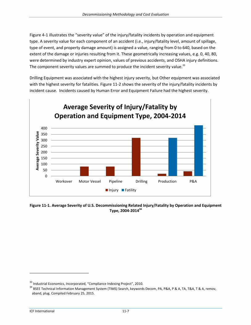
Decommissioning Methodology and Cost Evaluation
ICF International 11-7
Figure 4-1 illustrates the “severity value” of the injury/fatality incidents by operation and equipment
type. A severity value for each component of an accident (i.e., injury/fatality level, amount of spillage,
type of event, and property damage amount) is assigned a value, ranging from 0 to 640, based on the
extent of the damage or injuries resulting from it. These geometrically increasing values, e.g. 0, 40, 80,
were determined by industry expert opinion, values of previous accidents, and OSHA injury definitions.
The component severity values are summed to produce the incident severity value.33
Drilling Equipment was associated with the highest injury severity, but Other equipment was associated
with the highest severity for fatalities. Figure 11-2 shows the severity of the injury/fatality incidents by
incident cause. Incidents caused by Human Error and Equipment Failure had the highest severity.
Figure 11-1. Average Severity of U.S. Decommissioning Related Injury/Fatality by Operation and Equipment Type, 2004-201434
33
Industrial Economics, Incorporated, “Compliance Indexing Project”, 2010. 34
BSEE Technical Information Management System (TIMS) Search, keywords Decom, PA, P&A, P & A, TA, T&A, T & A, remov, aband, plug. Compiled February 25, 2015.
0
50
100
150
200
250
300
350
400
Workover Motor Vessel Pipeline Drilling Production P&A
Ave
rage
Se
veri
ty V
alu
e
Average Severity of Injury/Fatality by Operation and Equipment Type, 2004-2014
Injury Fatility
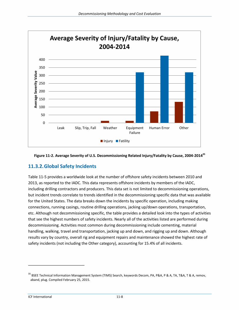
Decommissioning Methodology and Cost Evaluation
ICF International 11-8
Figure 11-2. Average Severity of U.S. Decommissioning Related Injury/Fatality by Cause, 2004-201435
11.3.2. Global Safety Incidents
Table 11-5 provides a worldwide look at the number of offshore safety incidents between 2010 and
2013, as reported to the IADC. This data represents offshore incidents by members of the IADC,
including drilling contractors and producers. This data set is not limited to decommissioning operations,
but incident trends correlate to trends identified in the decommissioning specific data that was available
for the United States. The data breaks down the incidents by specific operation, including making
connections, running casings, routine drilling operations, jacking up/down operations, transportation,
etc. Although not decommissioning specific, the table provides a detailed look into the types of activities
that see the highest numbers of safety incidents. Nearly all of the activities listed are performed during
decommissioning. Activities most common during decommissioning include cementing, material
handling, walking, travel and transportation, jacking up and down, and rigging up and down. Although
results vary by country, overall rig and equipment repairs and maintenance showed the highest rate of
safety incidents (not including the Other category), accounting for 15.4% of all incidents.
35
BSEE Technical Information Management System (TIMS) Search, keywords Decom, PA, P&A, P & A, TA, T&A, T & A, remov, aband, plug. Compiled February 25, 2015.
0
50
100
150
200
250
300
350
400
Leak Slip, Trip, Fall Weather EquipmentFailure
Human Error Other
Ave
rage
Se
veri
ty V
alu
e
Average Severity of Injury/Fatality by Cause, 2004-2014
Injury Fatility

Decommissioning Methodology and Cost Evaluation
ICF International 11-9
Table 11-5. Worldwide Reportable Incidents by Operation, 2010-201336
US Canada
Central America & Caribbean
Europe Africa Middle
East Asia Pacific & Australia
South America
Total
Tripping in/out (makeup/brakeout BHA, test tools, etc.)
Count 77 4 7 33 16 41 48 21 247
Percent 12.6 % 30.8 % 8.6 % 6.1 % 3.7 % 12.7 % 9.6 % 6.2 % 8.7 %
Making Connection Count 10 0 1 11 3 7 12 9 53
Percent 1.6 % 0.0 % 1.2 % 2.0 % 0.7 % 2.2 % 2.4 % 2.7 % 1.9 %
Routine Drilling Operations
Count 32 0 9 50 42 14 57 29 233
Percent 5.2 % 0.0 % 11.1 % 9.2 % 9.7 % 4.3 % 11.4 % 8.5 % 1.9 %
Running Casing/Tubing (rig up/down csg. tools)
Count 19 0 3 27 26 17 22 12 126
Percent 3.1 % 0.0 % 3.7 % 5.0 % 6.0 % 5.3 % 4.4 % 3.5 % 4.4 %
Laying Down/Picking up Pipe/Tubulars
Count 46 1 4 26 14 24 24 16 155
Percent 7.5 % 7.7 % 4.9 % 4.8 % 3.3 % 7.4 % 4.8 % 4.7 % 5.4 %
Material Handling Manual
Count 60 1 4 53 39 31 38 31 257
Percent 9.8 % 7.7 % 4.9 % 9.7 % 9.1 % 9.6 % 7.6 % 9.1 % 9.0 %
Material Handling Crane/ Cherry Picker /Forklift
Count 53 0 11 31 31 22 42 41 231
Percent 8.7 % 0.0 % 13.6 % 5.7 % 7.2 % 6.8 % 8.4 % 12.1 % 8.1 %
Rigging Up/Down (rig move preparation, rig move)
Count 28 0 3 9 13 11 17 5 86
Percent 4.6 % 0.0 % 3.7 % 1.7 % 3.0 % 3.4 % 3.4 % 1.5 % 3.0 %
Well Control (BOP) Count 27 0 2 10 12 25 14 11 101
36
International Association of Drilling Contractors (IADC) Incidents Statistics Program (ISP), 2010-2012.
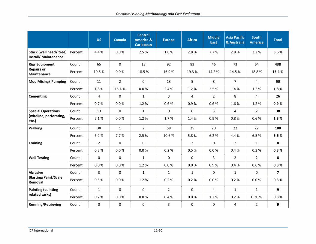
Decommissioning Methodology and Cost Evaluation
ICF International 11-10
US Canada
Central America & Caribbean
Europe Africa Middle
East Asia Pacific & Australia
South America
Total
Stack (well head/ tree) Install/ Maintenance
Percent 4.4 % 0.0 % 2.5 % 1.8 % 2.8 % 7.7 % 2.8 % 3.2 % 3.6 %
Rig/ Equipment Repairs or Maintenance
Count 65 0 15 92 83 46 73 64 438
Percent 10.6 % 0.0 % 18.5 % 16.9 % 19.3 % 14.2 % 14.5 % 18.8 % 15.4 %
Mud Mixing/ Pumping Count 11 2 0 13 5 8 7 4 50
Percent 1.8 % 15.4 % 0.0 % 2.4 % 1.2 % 2.5 % 1.4 % 1.2 % 1.8 %
Cementing Count 4 0 1 3 4 2 8 4 26
Percent 0.7 % 0.0 % 1.2 % 0.6 % 0.9 % 0.6 % 1.6 % 1.2 % 0.9 %
Special Operations (wireline, perforating, etc.)
Count 13 0 1 9 6 3 4 2 38
Percent 2.1 % 0.0 % 1.2 % 1.7 % 1.4 % 0.9 % 0.8 % 0.6 % 1.3 %
Walking Count 38 1 2 58 25 20 22 22 188
Percent 6.2 % 7.7 % 2.5 % 10.6 % 5.8 % 6.2 % 4.4 % 6.5 % 6.6 %
Training Count 2 0 0 1 2 0 2 1 8
Percent 0.3 % 0.0 % 0.0 % 0.2 % 0.5 % 0.0 % 0.4 % 0.3 % 0.3 %
Well Testing Count 0 0 1 0 0 3 2 2 8
Percent 0.0 % 0.0 % 1.2 % 0.0 % 0.0 % 0.9 % 0.4 % 0.6 % 0.3 %
Abrasive Blasting/Paint/Scale Removal
Count 3 0 1 1 1 0 1 0 7
Percent 0.5 % 0.0 % 1.2 % 0.2 % 0.2 % 0.0 % 0.2 % 0.0 % 0.3 %
Painting (painting related tasks)
Count 1 0 0 2 0 4 1 1 9
Percent 0.2 % 0.0 % 0.0 % 0.4 % 0.0 % 1.2 % 0.2 % 0.30 % 0.3 %
Running/Retrieving Count 0 0 0 3 0 0 4 2 9

Decommissioning Methodology and Cost Evaluation
ICF International 11-11
US Canada
Central America & Caribbean
Europe Africa Middle
East Asia Pacific & Australia
South America
Total
Anchors Percent 0.0 % 0.0 % 0.0 % 0.6 % 0.0 % 0.0 % 0.8 % 0.6 % 0.3 %
Handling Riser Count 7 0 0 5 9 2 9 9 41
Percent 1.2 % 0.0 % 0.0 % 0.9 % 2.1 % 0.6 % 1.8 % 2.7 % 1.4 %
Jacking Up/Down Operations
Count 4 0 0 0 1 1 3 0 9
Percent 0.7 % 0.0 % 0.0 % 0.0 % 0.2 % 0.3 % 0.6 % 0.0 % 0.3 %
Travel/ Transportation Count 12 1 0 7 5 2 3 6 36
Percent 2.0 % 7.7 % 0.00 % 1.3 % 1.2 % 0.6 % 0.6 % 1.8 % 1.3 %
Other Count 99 3 16 101 94 41 89 48 491
Percent 16.2 % 23.1 % 19.8 % 18.5 % 21.8 % 12.7 % 17.7 % 14.1 % 17.3 %

Decommissioning Methodology and Cost Evaluation
ICF International 11-12
Figure 11-3 and Figure 11-4 present data on fatalities and Lost Work Day Cases (LWDCs) by operation
and by category. Due to data availability restrictions, fatalities presented in both figures represent
fatalities from onshore and offshore operations. LWDCs are for offshore operations only. As with the
previous table, this data set does not represent decommissioning specific incidents, but incidents that
occur over the course of the offshore installation lifetime. Construction, commissioning, and
decommissioning activities - which include construction, fabrication and installation of equipment, test
activities to verify design specifications, disassembly, removal, and disposal - yielded 37 fatalities and
163 LWDCs over the three year period, accounting for approximately 9% of the incidents. Drilling,
workover and well services had the highest number of instances making up approximately 21% of the
incidents identified. Explosions and burns caused the highest number of fatalities, but “Struck by” and
“Caught in/under/between” incidents accounted for the most overall fatality and LWDC incidents.
Figure 11-3. Worldwide Fatalities and Lost Work Day Cases (LWDCs) by Operation, 2010-201237
37
International Association of Oil & Gas Producers (IOGP). Safety Performance Indicators 2010-2012.
0
50
100
150
200
250
300
350
400
450
Tran
spo
rt-l
and
Seis
mic
/su
rvey
op
era
tio
ns
Tran
spo
rt-a
ir
Div
ing,
su
bse
a, R
OV
Off
ice
, war
eho
use
,ac
com
mo
dat
ion
, cat
erin
g
Un
spec
ifie
d-o
the
r
Co
nst
ruct
ion
, co
mm
issi
on
ing,
dec
om
mis
sio
nin
g
Tran
spo
rt-w
ater
,in
clu
din
g m
arin
e a
ctiv
ity
Lift
ing,
cra
ne
, rig
gin
g,d
eck
op
erat
ion
s,
Pro
du
ctio
n o
pe
rati
on
s
Mai
nte
nan
ce, i
nsp
ecti
on
,te
stin
g
Dri
llin
g, w
ork
ove
r, w
ell
serv
ice
s
Nu
mb
er
of
Fata
litie
s o
r LW
DC
s
Fatalities (offshore and onshore)
LWDCs (offshore only)
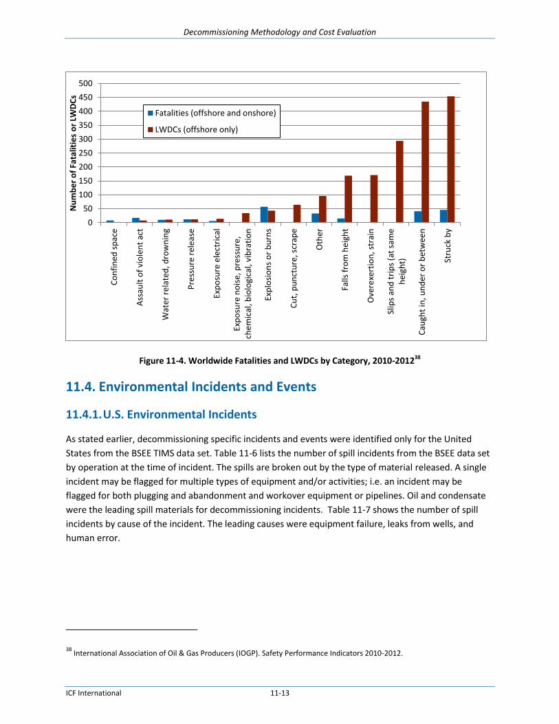
Decommissioning Methodology and Cost Evaluation
ICF International 11-13
Figure 11-4. Worldwide Fatalities and LWDCs by Category, 2010-201238
11.4. Environmental Incidents and Events
11.4.1. U.S. Environmental Incidents
As stated earlier, decommissioning specific incidents and events were identified only for the United
States from the BSEE TIMS data set. Table 11-6 lists the number of spill incidents from the BSEE data set
by operation at the time of incident. The spills are broken out by the type of material released. A single
incident may be flagged for multiple types of equipment and/or activities; i.e. an incident may be
flagged for both plugging and abandonment and workover equipment or pipelines. Oil and condensate
were the leading spill materials for decommissioning incidents. Table 11-7 shows the number of spill
incidents by cause of the incident. The leading causes were equipment failure, leaks from wells, and
human error.
38
International Association of Oil & Gas Producers (IOGP). Safety Performance Indicators 2010-2012.
0
50
100
150
200
250
300
350
400
450
500
Co
nfi
ned
sp
ace
Ass
ault
of
vio
len
t ac
t
Wat
er r
ela
ted
, dro
wn
ing
Pre
ssu
re r
ele
ase
Exp
osu
re e
lect
rica
l
Exp
osu
re n
ois
e, p
ress
ure
,ch
em
ical
, bio
logi
cal,
vib
rati
on
Exp
losi
on
s o
r b
urn
s
Cu
t, p
un
ctu
re, s
crap
e
Oth
er
Falls
fro
m h
eigh
t
Ove
rexe
rtio
n, s
trai
n
Slip
s an
d t
rip
s (a
t sa
me
hei
ght)
Cau
ght
in, u
nd
er o
r b
etw
een
Stru
ck b
y
Nu
mb
er
of
Fata
litie
s o
r LW
DC
s
Fatalities (offshore and onshore)
LWDCs (offshore only)

Decommissioning Methodology and Cost Evaluation
ICF International 11-14
Table 11-6. Number of U.S. Spill Incidents by Equipment Type and Spill Material, 2004-201439
Oil Diesel Condensate Hydraulic Natural Gas Other40
Total
Plugging and Abandonment
41
7 2 6 4 3 4 26
Production Equipment 2 0 1 0 0 1 4
Drilling Equipment 0 0 0 0 0 2 2
Workover Equipment 1 0 0 0 0 0 1
Completion Equipment 0 0 0 0 0 0 0
Motor Vessel 0 0 0 0 0 0 0
Pipeline 0 0 1 0 1 0 2
Helicopter 0 0 0 0 0 0 0
Totals 10 2 8 4 4 7 35
Notes: Incidents may be reported in multiple categories so the totals may not equal the total number of incidents.
Table 11-7. Number of U.S. Spill Incidents by Cause, 2004-201442
Oil Diesel Condensate Hydraulic Natural Gas Other43
Total
Equipment Failure 1 0 1 2 1 3 8
Human Error 1 0 2 0 1 1 5
Slip, Trip, Fall 0 0 0 0 0 0 0
Weather 1 0 1 0 1 0 3
External Damage 0 0 1 0 1 1 3
Leak 3 1 1 0 1 1 7
Upset H2O System 0 0 0 0 0 0 0
Overboard Fluid 0 0 0 0 0 0 0
Other 2 0 3 0 0 1 6
Totals 8 1 9 2 5 7 32
Notes: Incidents may be reported in multiple categories so the totals may not equal the total number of incidents.
39
BSEE Technical Information Management System (TIMS) Search, keywords Decom, PA, P&A, P & A, TA, T&A, T & A, remov,
aband, plug. Compiled February 25, 2015. 40
“Other” includes materials such as synthetic base mud, food grade hydraulic oil, water, and glycol. 41
These incidents were specifically flagged under P&A for the operation at the time of incident. Other incidents listed in the
table are also related to decommissioning activities, but were flagged as such in the description of the incident, not in the equipment/operation type.
42 BSEE Technical Information Management System (TIMS) Search, keywords Decom, PA, P&A, P & A, TA, T&A, T & A, remov,
aband, plug. Compiled February 25, 2015. 43
“Other” includes materials such as synthetic base mud, food grade hydraulic oil, water, and glycol.

Decommissioning Methodology and Cost Evaluation
ICF International 11-15
For decommissioning specific events in the United States, Figure 11-5 illustrates the average severity of
spill incidents by operation and equipment type and Figure 11-6 shows the total spill volume by
operation and equipment type. Drilling equipment related spills, most frequently associated with well
abandonment (both temporary and permanent), caused the highest average spill severity and the
greatest spill volumes.
Figure 11-5. Average Severity of U.S. Spills by Operation or Equipment Type, 2004-201444
44
BSEE Technical Information Management System (TIMS) Search, keywords Decom, PA, P&A, P & A, TA, T&A, T & A, remov, aband, plug. Compiled February 25, 2015.
0
50
100
150
200
250
Pipeline Production Workover Drilling P&A
Ave
rage
Se
veri
ty V
alu
e
Average Severity of Spill by Operation or Equipment Type, 2004-2014

Decommissioning Methodology and Cost Evaluation
ICF International 11-16
Figure 11-6. Total Spill Volume of U.S. Spills by Operation or Equipment Type, 2004-201445
Figure 11-7 shows the average severity of spill incidents by cause for decommissioning specific events in
the United States. Human error and equipment failure had overall the highest severity values. Leaks
were on the lower end of severity value despite having the second highest number of incidents. Figure
11-8 shows that the greatest volume of spills was caused by human error and equipment failure.
45
BSEE Technical Information Management System (TIMS) Search, keywords Decom, PA, P&A, P & A, TA, T&A, T & A, remov, aband, plug. Compiled February 25, 2015.
0
2000
4000
6000
8000
10000
12000
Pipeline Workover Production Drilling P&A
Tota
l Sp
ill V
olu
me
(ga
l)
Total Spill Volume by Operation or Equipment Type, 2004-2014

Decommissioning Methodology and Cost Evaluation
ICF International 11-17
Figure 11-7. Average Severity of U.S. Decommissioning Spills by Cause, 2004-201446
46
BSEE Technical Information Management System (TIMS) Search, keywords Decom, PA, P&A, P & A, TA, T&A, T & A, remov, aband, plug. Compiled February 25, 2015.
0
20
40
60
80
100
120
ExternalDamage
Weather Leak EquipmentFailure
Human Error Other
Ave
rage
Se
veri
ty V
alu
e
Average Severity of Spill by Cause, 2004-2014
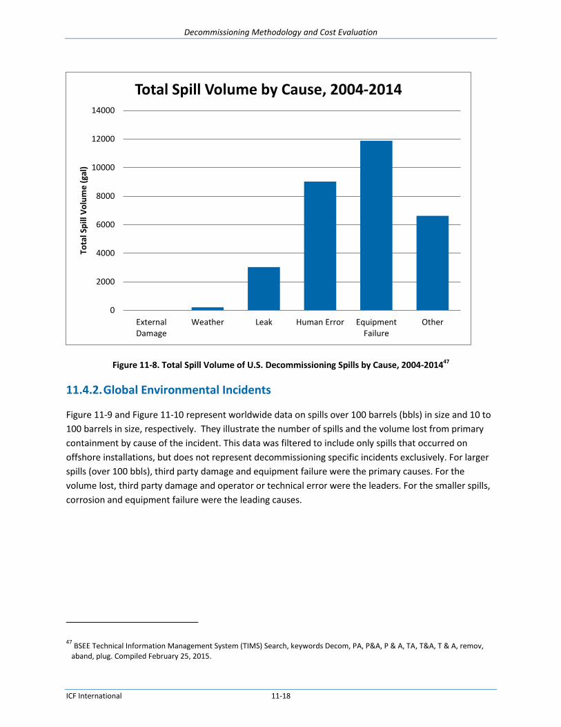
Decommissioning Methodology and Cost Evaluation
ICF International 11-18
Figure 11-8. Total Spill Volume of U.S. Decommissioning Spills by Cause, 2004-201447
11.4.2. Global Environmental Incidents
Figure 11-9 and Figure 11-10 represent worldwide data on spills over 100 barrels (bbls) in size and 10 to
100 barrels in size, respectively. They illustrate the number of spills and the volume lost from primary
containment by cause of the incident. This data was filtered to include only spills that occurred on
offshore installations, but does not represent decommissioning specific incidents exclusively. For larger
spills (over 100 bbls), third party damage and equipment failure were the primary causes. For the
volume lost, third party damage and operator or technical error were the leaders. For the smaller spills,
corrosion and equipment failure were the leading causes.
47
BSEE Technical Information Management System (TIMS) Search, keywords Decom, PA, P&A, P & A, TA, T&A, T & A, remov, aband, plug. Compiled February 25, 2015.
0
2000
4000
6000
8000
10000
12000
14000
ExternalDamage
Weather Leak Human Error EquipmentFailure
Other
Tota
l Sp
ill V
olu
me
(ga
l)
Total Spill Volume by Cause, 2004-2014

Decommissioning Methodology and Cost Evaluation
ICF International 11-19
Figure 11-9. Worldwide Number of Spills >100 bbl in Size and Volume Lost from Primary Containment, 2010-201248
Figure 11-10. Worldwide Number of Spills 10-100 bbl in Size and Volume Lost from Primary Containment, 2010-2012
11.5. Risk Ranking
Cranes utilized in decommissioning activities contributed to the highest number of safety incidents. Fires
caused by hot work or overheating equipment are also among the most frequent safety incidents during
decommissioning activities. Other types of incidents such as transportation accidents, although less
common, can lead to extremely severe injury and fatality incidents. The leading causes of safety
incidents are equipment failure and human error, based on both number of incidents and the severity of
the incidents.
48
International Association of Oil & Gas Producers (IOGP). Environmental Performance Indicators 2010-2012

Decommissioning Methodology and Cost Evaluation
ICF International 11-20
Environmental incidents are primarily caused by human error and equipment failure/corrosion. Human
error, weather, and third party damage were noted to yield more severe spills. However, for smaller
spills, equipment failure and corrosion were noted to be the most common causes. Although having
fewer identified incidents, spills during decommissioning-related incidents involving drilling equipment
caused the largest and most severe spills. The causes for these incidents were poor rig alignment, debris
accumulation, and seal failure in equipment.
Although worldwide data was only available for incidents that occurred during all stages of an offshore
installation lifetime, not just decommissioning, incident trends correlate to trends identified in the
decommissioning specific data that was available for the United States.

Decommissioning Methodology and Cost Evaluation
ICF International 12-1
12. Analysis of Decommissioning and Facility Removal Regulations ICF researched and analyzed the offshore and facility decommissioning regulations of federal agencies,
state agencies, and other worldwide jurisdictions with offshore O&G activities. Identified regulations
were parsed into individual requirements and compared and contrasted with BSEE regulations. The
main objective was to identify any gaps in the BSEE decommissioning regulations in order to
recommend improvements in the regulations to BSEE.
12.1. United States
12.1.1. Federal
BSEE 30 CFR Part 250 contains the decommissioning regulations as enforced by BSEE. Subpart Q (250.1700ff)
is the section dedicated to decommissioning regulations. General Requirements (250.1700-1709)
include definitions of decommissioning, obstructions and facility; who accrues decommissioning
obligations and the general requirements for decommissioning; when reports and applications need to
be submitted; and BOP, blowout, and well-control fluid requirements. Remaining sections provide the
regulations for Permanently Plugging Wells (250.1710-1717), Temporary Abandoned Wells (250.1721-
1723), Removing Platforms and Other Facilities (250.1725-1731), Site Clearance for Wells, Platforms,
and Other Facilities (250.1740-1743), and Pipeline Decommissioning (250.1750-1754). Refer to the
Regulatory Matrix in Section 11.4 for additional details on the individual requirements covered by
Subpart Q. 30 CFR 250.198 lists the documents incorporated by reference for 30 CFR 250. The only
reference related to decommissioning regulations (Subpart Q) listed is the API RP 53, Recommended
Practices for Blowout Prevention Equipment Systems for Drilling Wells, Third Edition, March 1997.
BSEE may grant a departure from the requirement to remove a nonproductive offshore O&G platform
for conversion to an artificial reef if the structure becomes part of a state program. States with Artificial
Reef Plans include Texas, Louisiana, Florida, Alabama, Mississippi, and California. The National Ocean
Atmospheric Administration (NOAA) also publishes the National Artificial Reef Plan, a guide for artificial
reef program managers and policy makers regarding how to understand artificial reef development.
The BSEE Idle Iron Policy (NTL 10-5) requires companies to dismantle and dispose of infrastructure after
Plug and Abandonment (P&A) activities are complete. Any decommissioned facility that has no
economically viable infrastructure is severely damaged or idle infrastructure on idle leases are
considered “idle iron”. The policy was put in place to prevent environmental or safety incidents that
could come about as a result of the “idle iron” being in place.
BSEE has issued Notices to Lessees and Operators (NTLs) related to decommissioning activities to clarify
and add additional guidance to regulations.

Decommissioning Methodology and Cost Evaluation
ICF International 12-2
General NTLs
NTL No. 2010-G05 Decommissioning Guidance for Wells and Platforms: This NTL, known as the “Idle
Iron” policy, requires companies to decommission infrastructure on active leases that is not
economically viable, is severely damaged, or is idle and to decommission all wells, structures, and
pipelines on terminated leases or pipeline rights-of-way are, i.e. “idle iron”. The policy was put in
place to establish an approach to ensure that idle infrastructure is decommissioned in a timely
manner. The NTL also provides additional guidance and clarification on well and platform removal
issues and provides definitions of “capable of production in paying quantities”, “downhole zonal
isolation”, “no longer useful for operations”, and “toppled platform”.
NTL No. 2010-P05 Decommissioning Cost Report Update: Notifies lessees and operators of the
availability of a decommissioning cost report.
NTL No. 2009-P04 Decommissioning of Pacific OCS Facilities: Provides guidelines for the permitting
process for decommissioning platforms, pipelines, and other O&G facilities on the Pacific OCS. This
NTL supersedes NTL 2001-P10 Decommissioning of Pacific OCS Facilities.
NTL No. 2003-G02 Ultimate Recovery Abandonment and Bypassing of Zones: Informs lessees and
operators that the GOM Office for Production and Development would be performing economic and
conservation evaluations of requests to abandon producing zones, including the conditions under
which lessees and operators must submit certain zone data prior to abandonment.
NTL No. 98-26 Minimum Interim Requirements for Site Clearance (and Verification) of Abandoned
Oil and Gas Structure in the Gulf of Mexico: Issued to update site clearance regulations.
Financial NTLs
NTL No. 2008-N07 Supplemental Bond Procedures: Clarifies procedures and criteria used to
determine when a supplemental bond is required to cover potential decommissioning liability.
Environmental NTLs
NTL No. 2012-N07 Oil Discharge Written Follow-up Reports: Provides clarification on the type of
information to be submitted in written follow-up reports for all oil discharges of one barrel or more.
NTL No. 2012-N06 Guidance to Owners and Operators of Offshore Facilities Seaward of the Coast
Line Concerning Regional Oil Spill Response Plans: Provides clarification and guidance on the
preparation and submittal of a regional Oil Spill Response Plan.
Joint NTL No. 2012-G01 Vessel Strike Avoidance and Injured/Dead Protected Species Reporting:
Updates guidelines on how to implement monitoring programs to minimize the risk of vessel strikes
to protected species and how to report observations of injured or dead protected species.
NTL No. 2012-G01 Marine Trash and Debris Awareness and Elimination: Provides background and
information on marine trash and debris awareness training.
NTL No. 2009-G04 Significant OCS Sediment Resources in the Gulf of Mexico: Provides guidance for
the avoidance and protection of significant OCS sediment resources in the GOM region.
NTL No. 2008-G17 Incident and Oil Spill Reports: Provides clarification on the types of incidents to
be reported, information no using the eWell Permitting and Reporting System, and specifies the
information to be included in reports.
Bureau of Ocean Energy Management (BOEM)

Decommissioning Methodology and Cost Evaluation
ICF International 12-3
30 CFR Part 550 regulates offshore oil and gas activities in the Outer Continental Shelf (OCS).
Decommissioning specific regulations in 30 CFR 550 specify the decommissioning information that must
be included in the Development and Production Plan (DPP) and Development Operations Coordination
Document (DOCD) (550.225).
U.S. Army Corps of Engineers (USACE) 33 CFR Part 320 provides the general regulatory policies for the USACE. USACE has regulatory
jurisdiction of coastal waters within three nautical miles offshore. Additional regulatory powers are also
exercised over navigable waters in the OCS (33 CFR Part 320.2(b) and 33 CFR Part 322.3(b)). USACE
issues Individual Permits (33 CFR Part 325), Letters of Permission (33 CFR 325.2(e)(1)) and Nationwide
Permits (33 CFR Part 330) for offshore activities in the jurisdictional area of USACE. Section 10 of the
River and Harbor Act of 1899 also prohibits the unauthorized obstruction or alteration of navigable
waters of the United States. USACE has authorization to approve any construction, extraction, or
depositing of material in these waters. USACE’s authority was extended to artificial islands, installations,
and other devices on the seabed to the limit of the OCS in the OCS Lands Act of 1953. The USACE does
not have regulations that specifically address decommissioning.
U.S. Environmental Protection Agency (EPA) The U.S. EPA does not have regulations that specifically address decommissioning of offshore structures,
but such activities are covered by the general environmental regulations that cover air emissions, water
quality, waste disposal, protection of biological resources, and other environmental aspects..
The Clean Water Act (CWA) pertains to the decommissioning of offshore O&G facilities through the
National Pollution Discharge Elimination System (NPDES) Permit Program. NPDES permits are required
for any discharges of pollutants to surface waters (CWA Section 301(a)) and are therefore necessary for
decommissioning activities.
The National Environmental Policy Act (NEPA) (40 CFR 1500-1508) is a policy requiring federal agencies
to integrate environmental values in their decision making. 40 CFR 1501.3 allows agencies to prepare an
environmental assessment (EA) to assist in the decision making process. If the results conclude that
significant adverse environmental effects may occur, then an Environmental Impact Statement (EIS)
must be prepared. 40 CFR 1502 details the sections that an EIS must include. 40 CFR 1503 includes
provisions for public comments on a Draft Environmental Impact Statement (DEIS), stating that
comments should be requested of appropriate local and state agencies, Indian tribes (when the effects
are on a reservation), and any agency that requested statements on the action proposed. The agency
will also request comments from the applicant and the public.
NEPA encourages agencies to tier their impact statements. When a broad EIS has previously been
prepared and a subsequent assessment is undertaken, the subsequent assessment only needs to
summarize the issues previously discussed and concentrate on the issues specific to the subsequent
action (40 CFR 1502.20). Programmatic NEPA analyses (PEA or PEIS) are used to evaluate actions that
are broad in scope and therefore allow for tiering of future NEPA documentation. For example, BOEM

Decommissioning Methodology and Cost Evaluation
ICF International 12-4
has prepared a PEIS for the OCS oil and gas leasing program49 which assesses, among other impacts, the
reasonably foreseeable impacts from common decommissioning activities. Site specific impacts would
be covered in a later site specific EA or EIS.
U.S. Coast Guard (USCG) Through the United States Aids to Navigation System (33 CFR Part 62 Subpart B) regulation, the USCG is
responsible for marking obstructions in areas of navigation. Potential obstructions could be generated in
the decommissioning process. The Aids to Navigation on Artificial Islands and Fixed Structures (33 CFR
Part 67) regulation requires obstruction lights and fog signals to be operated on all fixed structures. The
Control of Pollution by Oil and Hazardous Substances and Discharge Removal (33 CFR Part 153)
regulation requires that any parties who cause the discharge of oil or hazardous substances to notify the
USCG. The USCG will monitor and assist in the environmental response. Finally the Oil Pollution Act
(OPA) of 1990 provides provisions for oil liability, prevention, preparedness, and cleanup related to
offshore O&G facilities. The USCG does not have regulations that specifically address decommissioning.
U.S. Department of Transportation (USDOT) Office of Pipeline Safety (OPS) The Abandonment or Inactivation of Facilities (49 CFR 192.727) requires that operators provide an
operating and maintenance plan for decommissioning activities, as well as specific requirements that
the abandoned pipelines be disconnected from all sources and supplies or oil or gas. The USDOT does
not have regulations that specifically address offshore decommissioning.
National Oceanic and Atmospheric Administration (NOAA) The Fisherman’s Contingency Fund (43 U.S.C. 1482) was established to compensate fishermen for
economic and property losses caused by oil and gas obstructions in the OCS. Fishermen who prove that
they suffered losses as a result of damage from offshore oil and gas obstructions may be eligible for
compensation. This revolving fund is comprised of assessments paid by offshore oil and gas interests.
National Marine Fisheries Service (NMFS) Under the Endangered Species Act (ESA), the Marine Mammal Protection Act, and the Magnuson-
Stevens Fishery Conservation and Management Act, the NMFS ensures that during decommissioning
activities marine mammals, fish resources, and endangered marine species are not impacted. 50 CFR
Part 223 details restrictions applicable to threatened marine and anadromous species; restrictions will
vary depending on the threatened species specific to the area of the facility.
U.S. Fish & Wildlife Service (USFWS) The USFWS also has authority under the ESA to ensure the protection of threatened and endangered
species during decommissioning activities. The USFWS does not have regulations that specifically
address decommissioning.
49
BOEM, “Outer Continental Shelf Oil and Gas Leasing Program: 2012-2017, Final Programmatic Environmental Impact Statement”, BOEM 2012-030, 2012.

Decommissioning Methodology and Cost Evaluation
ICF International 12-5
12.1.2. States
Alabama Alabama Rules and Regulations of the State Oil and Gas Board of Alabama Governing Submerged
Offshore Land Operations (Rule 400-6-10) provide the state specific regulations on offshore O&G
activities in Alabama. In addition, Rule 400-2-8 documents Safety and Environment regulations. There is
no section dedicated to decommissioning activities. Alabama also has a Rigs to Reefs Program in place.
Refer to Table 12-1, the State Comparison Regulatory Matrix, for further details on specific
requirements.
Alaska The Alaska Administrative Code Title 22 Chapter 25 Article 2 covers the state regulations for the
decommissioning offshore O&G facilities. The state regulations are fairly in depth, requiring the removal
of all platforms, equipment, casings, and pilings unless a state or federal agency gives approval to leave
it in place. The Alaska Administrative Code Title 18 Chapter 75 Articles 3 and 5 detail contingency plans
and primary response actions for oil spills on offshore O&G facilities and vessels. Finally, under the
authority of the Alaska Department of Environmental Conservation, the Alaska Administrative Code Title
18 Chapter 83 contains the state specific Pollution Discharge Elimination System regulations.
Refer to Table 12-1, the State Comparison Regulatory Matrix, for further details on specific
requirements.
California Title 2 of the California Code of Regulations (2 CCR § 2124) specifies that on or before the expiration of a
lease, the lessee shall, at the option of the State Lands Commission, either surrender the leased
premises with all permanent improvements or remove such structures.
Title 14 of the California Code of Regulations (14 CCR § 1722 - 1749) contains specific plugging and
abandonment procedures, including waste disposal, spill contingency plans, pipeline and well plugging,
and site clearance requirements.
California Environmental Quality Act covers environmental impact review. The CEQA statute, California
Public Resources Code § 21000 et seq., codifies a statewide policy of environmental protection.
According to CEQA, all state and local agencies must give major consideration to environmental
protection prior to approving public and private activities.
The Lempert-Keene Seastrand Oil Spill Prevention and Response Act, under the California Department of
Fish and Wildlife Office of Spill Prevention and Response, covers all aspects of marine oil spill prevention
and response in California.
The California Marine Resources Legacy Act was passed in 2010 and establishes a program administered
by the Department of Fish and Wildlife to allow partial removal of offshore O&G structures. Similar to

Decommissioning Methodology and Cost Evaluation
ICF International 12-6
other Rigs to Reefs programs, a portion of the cost savings that result from a partial removal would be
apportioned to specific California State entities and funds.
Refer to Table 12-1, the State Comparison Regulatory Matrix, for further details on specific
requirements.
Louisiana The Louisiana Oil Spill Prevention and Response Act (OSPRA) of 2003 provides the regulatory framework
for spill response in the state. Parties involved in a threatened or actual unauthorized discharge of oil
are required to develop a state oil spill contingency plan, the contents or which are detailed in OSPRA.
Section 2469 of OSPRA (Derelict vessels and structures) details the responsibilities of operators in the
removal of a vessel or structure “involved in an actual or threatened unauthorized discharge of oil in
coast waters”. The Louisiana Administrative Code Title 43 (Natural Resources) contains the state well
plugging procedures.
As mentioned above, the Louisiana Department of Wildlife and Fisheries runs an Artificial Reef Program.
The program began in 1986 and to date 71 offshore O&G companies have participated in the program.
Under the program, companies also donate half their realized savings over a traditional removal process
into Louisiana’s Artificial Reef Trust Fund. Interested parties submit an application covering a number of
factors including conservation, economics, fish and wildlife values, aesthetics, among others.
Refer to Table 12-1, the State Comparison Regulatory Matrix, for further details on specific
requirements.
Mississippi Mississippi has state specific rules for drilling offshore wells (Rule OS-5) that Include plugging and
abandonment requirements. Rule OS-8 highlights requirements for liquid disposal and solid waste
disposal. Rule OS-11 provides details on financial securities for wells and pipelines for offshore
installations. Mississippi also has an Artificial Reef Program in place.
Refer to Table 12-1, the State Comparison Regulatory Matrix, for further details on specific
requirements.
Texas The Texas Administrative Code Title 30 covers Environmental Quality regulations, including spill
prevention and control (Chapter 327). The Railroad Commission of Texas has jurisdiction over wells in
state waters and Statewide Rules 13 and 14 provide well plugging requirements. The Texas Artificial
Reef Program is operated by the Texas Parks & Wildlife Department. It was created in 1990 through the
Coastal Fisheries Division. For offshore (major) structures RCT requests U.S. Department of Army, Corps
of Engineers to perform engineering and environmental reviews.
Refer to Table 12-1, the State Comparison Regulatory Matrix, for further details on specific
requirements.
Decommissioning Methodology and Cost Evaluation
ICF International 12-7
12.2. Other IRF Member Countries
Australia The federal entity in Australia is the National Offshore Petroleum Safety and Environmental
Management Authority (NOPSEMA), which functions and powers conferred on it under the Offshore
Petroleum and Greenhouse Gas Storage Act 2006 (OPGGS Act) and its regulations. The OPGGS Act
primarily provides authority to regulate health and safety, well integrity and environmental
management of petroleum exploration and development activities in Australia’s offshore areas beyond
the first three nautical miles of the territorial sea. Other offshore facilities that are within the first three
nautical miles are regulated by State and Territory legislation.
NOPSEMA is a cost recovery agency and the Offshore Petroleum and Greenhouse Gas Storage
(Regulatory Levies) Act 2003 enables specific levies for Occupational Health Safety, Well Integrity and
Environmental Management regulatory activities.
The NOPSEMA regulations related to offshore O&G activities are- Select Legislative Instrument 2011 No.
54. - Offshore Petroleum and Greenhouse Storage (Resource Management and Administration)
Regulations 2011, Statutory Rules 1999 No. 228 - Offshore Petroleum and Greenhouse Gas Storage
(Environment) Regulations 2009, Select Legislative Instrument 2009 No. 382 - Offshore Petroleum and
Greenhouse Gas Storage (Safety) Regulations 2009, and Statutory Rules 2004 No. 315 - Offshore
Petroleum and Greenhouse Gas Storage (Regulatory Levies) Regulations 2004. Select Legislative
Instrument 2011 No. 54 stipulates that operators must seek approval from NOPSEMA prior to any
abandonment activities. The process involves an overall abandonment plan as well as an environmental
assessment plan.
Refer to Table 12-2, the International Comparison Regulatory Matrix, for further details on specific
requirements.
Brazil The Brazilian National Petroleum Agency (ANP) is the main regulating body associated with offshore
O&G decommissioning. Overall obligations for decommissioning are in the specific Concession
Agreement that the operator enters into with ANP, but general technical requirements and surrender of
acreage are covered in ANP’s Ordinance No. 25/2002. While decommissioning, the operators must all
comply with applicable environmental laws and international best practices as laid out in International
Conventions.
Refer to Table 12-2, the International Comparison Regulatory Matrix, for further details on specific
requirements.
Canada The Canadian federal government controls O&G activities on frontier lands and each province also has
their own specific regulations for activities in their province. The Canada Oil and Gas Operations Act
highlights provisions relating to well abandonment, including spills and debris. The Canadian

Decommissioning Methodology and Cost Evaluation
ICF International 12-8
Environmental Assessment Act (CEEA) 2012 requires operators to submit an environmental assessment
for projects that considers factors including cumulative effects, mitigation measures, and public
comments. Nova Scotia and the Government of Canada implemented the Canada-Nova Scotia Offshore
Petroleum Resources Accord Implementation Act as an agreement on how to manage offshore
petroleum resources.
Refer to Table 12-2, the International Comparison Regulatory Matrix, for further details on specific
requirements.
Denmark Regulators of offshore oil and gas licensing and the offshore environment, The Danish Energy Agency
(DEA), Danish Environmental Protection Agency (DEPA), and the Danish Maritime Authority (DMA)
provide oversight in the determination of the decommissioning operations. DEPA regulates the
environmental action plans, discharge permits, and oil and chemical spill contingency plans through the
Act on Protection of the Marine Environment. Through Orders (No. 35 and No. 883), the DMA provides
financial liability information for oil spills from marine vessels. The Danish Working Environment
Authority (DWEA) regulates how the decommissioning work to be carried out with the Offshore Safety
Act.
Refer to Table 12-2, the International Comparison Regulatory Matrix, for further details on specific
requirements.
Mexico There are no specific decommissioning obligations for contractors from the National Hydrocarbons
Commission (CNH); however specific decommissioning and abandonment provisions are specified in
contracting guidelines executed with the contractor. Typically, agreements require that the contractor
be responsible for all expenses associated with the decommissioning activities and the contractor will be
liable for any problems arising from decommissioning for ten years following the termination of the
contract.
The General Law of Ecological Balance and Environmental Protection (LGEEPA) requires the submission
of an Environmental Impact Assessment (EIA) which may cover decommissioning activities. The inclusion
of decommissioning activities is at the CNH discretion.
Refer to Table 12-2, the International Comparison Regulatory Matrix, for further details on specific
requirements.
The Netherlands The State Supervision of Mines (an agency of the Ministry of Economic Affairs) supervises offshore O&G
activities. The current mining legislation consists of the Mining Act, the Mining Decree, and the Mining
Regulation. Decommissioning specific portions of the legislation can be found in the Mining Decree
5.1.4, 5.2.3, and 5.2.4, covering installations located above and below surface water.

Decommissioning Methodology and Cost Evaluation
ICF International 12-9
Refer to Table 12-2, the International Comparison Regulatory Matrix, for further details on specific
requirements.
New Zealand The Maritime Transport Act 1994 was put in place to limit the input of harmful substances into the sea,
and details oil spill response strategies of vessels. The Health and Safety Employment Regulations
stipulate that decommissioning procedures must be conducted in a safe manner. A revised safety case
that covers decommissioning operations has to be submitted to WorkSafe NZ prior to activities
commencing.
Refer to Table 12-2, the International Comparison Regulatory Matrix, for further details on specific
requirements.
Norway The Petroleum Act is the regulatory authority for decommissioning activities in Norway. The Act requires
a decommissioning plan, impact assessment, and plans for public consultation. Norwegian regulations
do not have specific abandonment requirements. Instead, the Act references NORSOK, the Norwegian
petroleum standards that were developed by the Norwegian petroleum industry, to ensure safety and
efficacy for petroleum industry operations. NOROSK Standard D-010, in particular, provides detailed
guidance on well plugging procedures.
Refer to Table 12-2, the International Comparison Regulatory Matrix, for further details on specific
requirements.
United Kingdom (UK) The UK has robust regulations and requirements associated with offshore O&G activities. The UK
Petroleum Act 1998, as amended by the Energy Act 2008, details the requirements for decommissioning
of offshore installations. The Department of Energy and Climate Change (DECC) is in charge of ensuring
that operators are in compliance with the regulations. The leading trade association for the UK offshore
O&G activities, UK Oil & Gas, issues guidelines for decommissioning activities to assist operators.
Additional safety, environmental protection, and pollution prevention laws and regulations are also in
place under the regulatory framework in the UK that may affect decommissioning activities. Agencies
involved include the DECC; Department of the Environment Transport and the Regions; Health and
Safety Executive; and Maritime and Coastguard Agency, among others.
Refer to Table 12-2, the International Comparison Regulatory Matrix, for further details on specific
requirements.
12.3. Other Jurisdictions
International Conventions

Decommissioning Methodology and Cost Evaluation
ICF International 12-10
The Geneva Convention on the Continental Shelf 1958, in particular Article 5, stipulates that any
activities in the continental shelf must not result in interference with navigation, fishing, or the
conservation of the living resources of the sea. With respect to decommissioning, the Convention states
that any installations which are abandoned must be removed in their entirety. There are 43 signatories
and 58 parties of the Convention50.
The UN Convention on the Law of the Seas 1982 (UNCLOS) allows for partial removal of offshore
structures provided that International Maritime Organization (IMO) criteria are met, specifically that the
partial removal should have regard for fishing, protection of the marine environment, and the rights of
other states. The location of the remaining portions of the installation must be publicly stated. UNCLOS
has 157 signatories and 167 parties51.
IMO Guidelines of 1989 require the complete removal of all structures in water less than 100m and
structures less than 4,000 tons. In addition, installations after 1998 must be designed to be removed
when they are ready to be decommissioned.
The London Convention provides specific guidance for dumping platforms at sea as well as providing
guidance for the placement of artificial reefs. The objective of the Convention is to protect the marine
environment from human activities. There are 87 parties of the London Convention52.
The Convention for the Protection of the Marine Environment of the North-East Atlantic 1992 (OSPAR)
was put in place to control disposal of waste at sea and discharges to land. The OSPAR Decision 98/3
provides additional details on specific decommissioning requirements. There are 16 Contracting Parties
to OSPAR53.
12.4. Regulatory Matrix
Based on the regulations described above, Tables 12.1 and 12.2 provide matrices of the specific
requirements by State and Country, respectively, to compare across all the regulating bodies.. The US
regulatory requirements in the matrix reflect requirements across all federal agencies and the
international requirements noted in this table also span across different agencies.
50
https://treaties.un.org/Pages/ViewDetails.aspx?src=TREATY&mtdsg_no=XXI-4&chapter=21&lang=en 51
http://www.un.org/depts/los/reference_files/chronological_lists_of_ratifications.htm 52
http://www.imo.org/OurWork/Environment/LCLP/Pages/default.aspx 53
http://www.ospar.org/content/content.asp?menu=00340108070026_000000_000000

Decommissioning Methodology and Cost Evaluation
ICF International 12-11
Table 12-1. State Comparison Regulatory Matrix54
FEDERAL AK AL CA LA MS TX
Plans and Approvals
Decommissioning
Plan, Application, or
Approval
30 CFR 250.1704. Initial platform
removal application, final platform
removal application, pipeline
decommissioning application, and
Application for Permit to Modify
required. Dates vary by application
type (2 years prior for platforms and
before decommissioning pipelines).
Requirements vary by application
type.
20 AAC 25.105. Application for
Sundry Approvals must be submitted
prior to well abandonment, plugging,
or suspension. Dates are not
provided. Applications include reason
for abandonment and statement of
proposed work.
State Oil and Gas Board of
Alabama Administrative Code
400-6-10. Prior to
abandonment activities, the
operator must provide the
Supervisor with the proposed
methods and procedures.
Abandonment cannot begin
until approval is given by the
Supervisor.
CA CCR Title 14 Division 2 Chapter 4
Subchapter 1.1 Article 3.1745.
Plugging and abandonment activities
require approval from the
Supervisor. Applications include a
detailed work plan. Any applications
without response in 10 days are
deemed to be approved
43 LAC 19.137. Notification
of plugging must be made in
writing to the local District
Office and once approved
will receive a work permit.
LAC 43:XI.311. A procedural
plan for site clearance
verification of platform, well
or structure abandonment
shall be developed by the
lessee and submitted to the
commissioner of
conservation for approval
with the permit application
for platform or structure
removal.
Rule OS-5. Plugging and
abandonment operations must
not begin without approval from
an authorized representative of
the board.
State Statue- 53-3-101. Need a
permit from State Oil and Gas
Board for construction on
offshore facilities.
Statewide Rule 14,
Plugging. Operator must
submit a "Notice of
Intention to Plug and
Abandon" prior
commencing
abandonment
procedures.
Environmental
Impact, Damage
Prevention, or
Rehabilitation Plan
30 CFR 250.1712, 1726, 1727, 1752:
Brief assessment of the
environmental impacts of the removal
operations and procedures and
mitigation measures to take to
minimize such impacts
18 AAC 75.405. At least 60 days
before submitting an application for
approval of a new oil discharge
prevention and contingency plan.
18 AAC 75.425. Under the umbrella
of environmental conservation
policy. The operator must submit Oil
Discharge Prevention and
Contingency Plan must be in a form
that is usable as a working plan for oil
discharge prevention, control,
containment, cleanup, and disposal.
335-8-1-08. (2) Upon receipt of
a permit application for a use
subject to the management
program, the state agency shall
send to the Department an
informational copy of the
complete application along with
any supporting documents
submitted by the applicant.
Upon receipt, the Department
shall begin its review process
and shall initiate appropriate
interagency coordination.
CA CCR Title 14 Division 2 Chapter 4
Subchapter 2 Article 3.1776. The
operator must submit a plan for
lease restoration, which must begin
within 3 months and completed
within one year of abandonment of
last well.
LAC 43:XI.311. Rehabilitation
Information provided under
procedure plan.
Statewide Rule 28. All wastes
and other materials, including
petroleum-contaminated soil,
shall be removed from the
location and associated sites and
disposed of in accordance with
appropriate permit(s) or
regulations(s); provided,
however, that petroleum-
contaminated soil may be
approved by the Supervisor for
on-site remediation.
16 TAC 8(d)(5). Permits to
store, handle, treat and
dispose of oil and gas
wastes are issued under
Statewide Rules 8(drilling
fluid disposal,
landfarm/landtreatment),
9, 46 (disposal/injection
well), and 57 (reclamation
plant).
U.S. Army Corps of
Engineers - Public notice
(12/2012) RGP-11 –
Submit plans for
restoration of the surface
under Surface Use and
Operations Plan.
54
Refer to the regulation referenced for additional details and specifics for requirements. This table does not include all specifics for the requirements mentioned.

Decommissioning Methodology and Cost Evaluation
ICF International 12-12
FEDERAL AK AL CA LA MS TX
Financial Assurance 30 CFR 556 Subpart I. Lease bond for
exploration - $200,000 – Individual,
$1 million – area wide; for
development/production $500,000 –
Individual, $3 million – area wide.
Supplemental/additional bonds will
vary case by case basis.
30 CFR 556.53(e). The Regional
Director will determine the amount of
supplemental bond required to
guarantee compliance. The Regional
Director will consider potential
underpayment of royalty and
cumulative obligations to abandon
wells, remove platforms and facilities,
and clear the seafloor of obstructions
in the Regional Director's case-specific
analysis. Operator may also apply for
supplemental bond waiver.
20 AAC 25.025(b). A bond and, if
required, security must be in the
amount of not less than $100,000 to
cover a single well or not less than
$200,000 for a blanket bond covering
all of the operator's wells in the
state, except that the commission
will allow an amount less than
$100,000 to cover a single well if the
operator demonstrates to the
commission's satisfaction in the
application for a Permit to Drill (Form
10-401) that the cost of well
abandonment and location clearance
will be less than $100,000.
State Oil and Gas Board of
Alabama Administrative Code
400-1-2-.03 details bonding
requirements based on depth
of well for oil and gas
operations, including
assurances against any
pollution of the sea, and all
surface and groundwater.
CA Pub. Res. Code 3205. Operators of
offshore wells must post a bond (an
amount determined by the State Oil
and Gas Supervisor) to cover
abandonment costs. The amount can
be adjusted by the Supervisor no
more than once every 3 years.
43 LAC 19.104. Financial
security remains in effect
until after plugging and
abandonment and site
restoration is complete,
pending inspection.
Rule OS-11. A bond of $100,000
for each well or pipeline, or
$200,000 for all wells and
pipelines, must be filed with the
Board before drilling any
offshore wells.
S.B. 1103. Requires
financial security for
operators of oil and gas
facilities. Financial
securities options,
including a blanket bond
or lien on field
equipment. (16 TAC 3.78)
Public Consultation National Environmental Protection
Act. Environmental Impact
Statements are available for public
comment for a minimum of 45 days.
20 AAC 25.565(b). The commission
will promptly schedule a public
hearing on the plan and give public
notice of the hearing in accordance
with AS 31.05.050(b). The hearing
will be scheduled at least 10 days
after the date of the public notice.
State Oil and Gas Board of
Alabama Administrative Code
335-8-1-.14(4) Public notice
may not be required for
modifications, and permit
extensions or renewals in which
the impact is expected to be
equal to or less than that
originally permitted. All
editorial changes and permit
name changes shall not be
subject to the public notice
requirements of this rule.
Marine Resources Legacy Act.
Application for partial removal must
be made available for public
comment and a public hearing must
be held in the county nearest to the
site of the offshore structure.
43 LAC 19.137. In the event
any owner(s) responsible for
plugging any well fails to do
so, and after a diligent effort
has been made by the
department to have said
well plugged, then the
commissioner may call a
public hearing to show cause
why said well was not
plugged.
State Statue- 53-3-101. The State
Oil and Gas Board upon the
application of any interested
person shall, after notice as
herein provided, hold a hearing
to consider the need for the
operation.
Rule 28. Any interested party at
any time shall have the right to
review by the Board upon notice
and hearing with respect to the
administration of any provision
hereof.
16 TAC 3.7. If the director
determines that a hearing
is in the public interest, a
hearing shall be held.
Removal Guidelines

Decommissioning Methodology and Cost Evaluation
ICF International 12-13
FEDERAL AK AL CA LA MS TX
Well P&A 30 CFR 250.1715. Generally requires
minimum 200 ft long cement plugs to
isolate oil, gas, and freshwater zones
or to plug casings, with additional
bridge plugs or cement retainers
allowed or required in some
situations.
22 AAC 25.112 and 115. Minimum
requirements for plugging uncased
wellbores are by the displacement
method (cement plug generally
placed from 100 ft below the base to
50 ft above the freshwater strata) or
by the downsqueeze method using a
retainer or production packer set
from 50 to 100 ft from above the
casing shoe.
State Oil and Gas Board of
Alabama Administrative Code
400-6-10. The storage cavity
will be filled with water
saturated to a brine
concentration of 90% or greater
and a bridge plug will be placed
within 150 ft above the cement
plug in the production casing.
400-2-4-.09. To facilitate casing
removal upon well
abandonment, cement may be
washed out or displaced to a
depth not to exceed forty (40)
feet below the waters floor,
unless otherwise approved by
the Supervisor.
CA CCR Title 14 Division 2 Chapter 4
Subchapter 1.1 Article 3.1745.
Cement plugs to total depth or at
least 100 feet below each oil or gas
zone in uncased holes, with
minimum 200 ft cement plugs across
an intrazone freshwater-saltwater
interface.
43 LAC 19.137. A cement
plug of at least 100 ft must
be placed to the top of the
screen or liner.
Rule OS-5. Generally requires
cement plugs to extend a
minimum of 100 ft below the
casing/bottom to 100 ft above
the casing/top of any oil, gas, or
freshwater zones, with
additional retainers and bridges
required in some situations
Statewide Rule 14,
Plugging. Operator must
follow requirements set
forth in the approved
"Notice of Intention to
Plug and Abandon" form.
Operators may only use
approved cementers to
plug their well.
14 TAC 3.14. This plug
shall be a minimum of
100 feet in length and
shall extend at least 50
feet above the shoe and
at least 50 feet below the
shoe.
Structures 30 CFR 250.1728. Platforms and
facilities must be removed to at least
15 ft below the mudline. Alternate
depths may be approved in some
situations.
22 AAC 25.172. All obstructions must
be removed to a depth of at least 1 ft
below the mudline for fixed offshore
platforms and 5 ft for a rig or floating
vessel. One year after abandonment
of a well drilled from a beach,
artificial island, or natural island,
operator must ensure the integrity of
the location within one year of
abandonment. The commission will
conduct an inspection to verify
location condition.
State Oil and Gas Board of
Alabama Administrative Code
400-2-4-.13. (1) All casing,
wellhead equipment, platforms,
fixed structures, and pilings
shall be removed to a depth of
at least fifteen (15) feet below
the waters floor.
CA CCR Title 14 Division 2 Chapter 4
Subchapter 1.1 Article 3.1745. All
casing and anchor piling cut and
removed no more than 5 ft below
the ocean floor. Ocean floor must be
cleared of any obstructions, unless
prior approval from marine
navigation and wildlife agencies
LAC 43:XI.311. Well and
platform locations shall be
cleared of all obstructions.
All casing and anchor piling
shall be removed to a depth
of at least 10 feet below the
mudline.
Rule OS-5. All casing and piling
should be removed to at least 15
ft below the waters' floor and
the location must be dragged to
clear any obstructions.
31 TAC 9.91. Remove all
equipment, structures,
machinery, tools,
supplies, and other items
on the property and
otherwise restore the
property to the condition
it was in immediately
preceding issuance of
that lease.

Decommissioning Methodology and Cost Evaluation
ICF International 12-14
FEDERAL AK AL CA LA MS TX
Location Clearance 30 CFR 250.1740. The site must be
cleared of all obstructions. A trawl
must be dragged across the site for
water depths less than 300 ft. For
water depths greater than 300 ft,
sonar equipment may be used to
ensure the site is clear.
22 AAC 25.172. All obstructions must
be removed to a depth of at least 1 ft
below the mudline for fixed offshore
platforms and 5 ft for a rig or floating
vessel. One year after abandonment
of a well drilled from a beach,
artificial island, or natural island,
operator must ensure the integrity of
the location within one year of
abandonment. The commission will
conduct an inspection to verify
location condition.
State Oil and Gas Board of
Alabama Administrative Code
400-2-4-.13. (1) All casing,
wellhead equipment, platforms,
fixed structures, and pilings
shall be removed to a depth of
at least fifteen (15) feet below
the waters floor.
CA CCR Title 14 Division 2 Chapter 4
Subchapter 1.1 Article 3.1745. All
casing and anchor piling cut and
removed no more than 5 ft below
the ocean floor. Ocean floor must be
cleared of any obstructions, unless
prior approval from marine
navigation and wildlife agencies
LAC 43:XI.311. Well and
platform locations shall be
cleared of all obstructions.
All casing and anchor piling
shall be removed to a depth
of at least 10 feet below the
mudline.
Rule OS-5. All casing and piling
should be removed to at least 15
ft below the waters' floor and
the location must be dragged to
clear any obstructions.
U.S. Department of Army,
Corps of Engineers, Fort
Worth District. Notice to
Oil and Gas Lessees and
Operators - #10. Submit
plans for restoration of
the surface, with
practices necessary to
rehabilitate all disturbed
areas including any access
roads no longer needed.
Pipelines 30 CFR 250.1751 and 1752. A pipeline
may be decommissioned in place
after approval by pigging and flushing
the pipeline before filling seawater
and plugging. The pipeline must then
be buried at least 3 ft below the
seafloor or have each end covered
with protective concrete mats. Prior
to removal, pipelines must also be
pigged and flushed.
22 AAC 15.172. Upon abandonment
of an offshore production facility,
unless agreed to by the surface
owner, the operator is required to
remove all materials, supplies
structures, and installations from the
location.
State Oil and Gas Board of
Alabama Administrative Code
400-3-4-.16. When a location is
abandoned, all material, debris
and equipment, such as drill
pipe, casing, tubing, treaters,
separators, tanks, and other
production, injection, and
above-ground pipeline
equipment and materials shall
be removed from the location.
CA CCR Title 14 Division 2 Chapter 4
Subchapter 2 Article 3.1776.
Pipelines must be purged of oil and
filled with an inert material.
43 LAC 5.30141 (oil) &
11.2927 (gas). A pipeline
may be abandoned in place
must be disconnected, filled
with water or inert
materials, and sealed at the
ends. (49 CFR 195.59 (oil) &
49 CFR 192.727 (gas))
Statewide Rule 28 – Remove
above ground pipelines. All
underground or buried lines shall
be flushed and capped at both
ends.
16 TAC 7.70. A pipeline
may be abandoned in
place must be
disconnected, filled with
water or inert materials,
and sealed at the ends.
(49 CFR 195.59 (oil) & 49
CFR 192.727 (gas))

Decommissioning Methodology and Cost Evaluation
ICF International 12-15
FEDERAL AK AL CA LA MS TX
Temporary
Abandonment
30 CFR 250.1721. Generally a 100-ft
bridge or cement plug must be set. An
application to modify must be
submitted prior to temporary
abandonment.
22 AAC 25.072. The operator must
provide a description of condition of
the wellbore upon shutdown and
when the operations will resume.
Operations must resume within 12
months.
State Oil and Gas Board of
Alabama Administrative Code
400-1-4-.17. (1). An operator
may request that a well be
placed in a temporarily
abandoned status by
submitting a written request to
the Supervisor describing its
future utility. A well may be
classified as a temporarily
abandoned well upon a
showing that the well has
future utility. The well will be
placed in a temporarily
abandoned status for a period
of not more than one (1) year.
CA CCR Title 14 Division 2 Chapter 4
Subchapter 1.1 Article 3.1745. Wells
must be mudded and cemented as
under well P&A requirements, with
certain requirements not needed. A
mechanical bridge plug must be set
in the well between 15 and 200 ft
below the ocean floor for plaform
sites.
43 LAC 19.137. Any drilling
well which is to be
temporarily abandoned and
the rig moved away, shall be
mudded and cemented as it
would be for permanent
abandonment, except a
cement plug at the surface
may be omitted.
Rule OS-5. Temporarily
abandoned wells must be
mudded and cemented as under
well P&A requirements, with
certain requirements not
needed. A mechanical bridge
plug must be set in the well
between 15 and 200 ft below the
ocean floor for platform sites.
14 TAC 3.14. Plug shall be
a minimum of 100 feet in
length and shall extend at
least 50 feet above the
shoe and at least 50 feet
below the shoe. An
application must be
submitted prior to
temporary abandonment.
Removal
(Partial/Full, Full
Only, Artificial
Reefs)
30 CFR 250.1730. Partial removal or
toppling in place may be allowed if
the structure becomes part of a State
artificial reef program and the
structure satisfied the USCG
navigational requirements.
22 AAC 25.105. A well must be
abandoned before the full removal of
the drill rig.
Artificial Reef Law.
Materials/vessels must be
inspected and permitted by the
USACE, Department of
Conservation and Natural
Resources, and Marine
Resources Division.
Marine Resources Legacy Act. Allows
partial removal of platform if the
Ocean Protection Council determines
there is a net benefit to the marine
environment. Applicant must submit
application with a plan to manage
the structure after partial removal
and provide an opportunity for public
comment. Cost savings are
apportioned to the CA Endowment
for Marine Preservation, General
Fun, Fish and Game Preservation
Fund, Coastal Act Services Fund, and
the Board of Supervisors of the local
county. The percent of cost savings
transmitted to the above are 55% for
approvals by 2017, increasing to 80%
after 2023.
Louisiana Fishing
Enhancement Act. Created
the Artificial Reef Program in
1986. The structure must
have an 85 ft minimum
clearance below the mean
low sea level of the water
surface. The operator must
donate a specified amount
to the Conservation Fund.
Mississippi Artificial Reef Plan.
The structure must have a 50 ft
minimum clearance below the
mean low sea level of the water
surface. The operator must
donate a specified amount to the
Artificial Reef Fund.
Texas Artificial Reef Plan.
Operators must donate
half their realized savings
from not having to take
the rigs to shore to the
Texas Artificial Reef Fund,

Decommissioning Methodology and Cost Evaluation
ICF International 12-16
FEDERAL AK AL CA LA MS TX
Material Disposal 30 CFR 250.1726. Platform or other
facility disposal plans must be
submitted during initial removal
application.
18 AAC 75.425. Site disposal plans
must be submitted as Oil Discharge
Prevention and Contingency Plan.
State Oil and Gas Board of
Alabama Administrative Code
335-8-2-.10 (1) All new energy
facilities located wholly or
partially within the coastal area
and which require a state
agency permit must also
receive coastal consistency
from the Department prior to
any land clearing or
construction.
CA CCR Title 14 Division 2 Chapter 4
Subchapter 2 Article 3.1775 and
1776. Oilfield waste must be
disposed of in a manner as not to
cause damage to life, health,
property, surface waters, or natural
resources and must conform to
Department of Toxic Substances
Control Requirements
43 LAC 19.503. Assess the
waste generated and send
the waste to approved sites
(in accordance with the type
of the waste generated.)
Rule OS-8. Liquid waste materials
that may be harmful to aquatic
life must be treated to avoid the
disposal of harmful substances
into the waters. Solid waste may
not be disposed of into the
waters without prior approval of
the supervisor. Without
approval, they must be
incinerated or transported to
shore for disposal.
16 TAC 3.98 Activities
associated with the
operation, abandonment,
and proper plugging of
wells subject to the
jurisdiction of the
commission to regulate
the exploration,
development, and
production of oil or gas or
geothermal resources.
Environmental
Spill Response 30 CFR 250. Oil-Spill Response Plans
must demonstrate that the operator
can respond quickly and effectively
when oil is discharged from the
facility. The plan must be submitted
prior the facility being used.
18 AAC 75.425. An Oil Discharge
Prevention and Contingency Plan
must be submitted to the DEC.
State Oil and Gas Board of
Alabama Administrative Code
400-2-8. Operators must have
an area contingency spill
response plan.
CA CCR Title 14 Division 2 Chapter 4
Subchapter 2 Article 3.1743. A spill
contingency plan must be on file with
the Division prior to operations. All
spills must be reported to agencies
specified in the CA Oil Spill Disaster
Contingency Plan and in the National
Oil Hazardous Substances Pollution
Contingency Plan.
OSPAR Section 2459. The
State will develop and
distribute to the public a
contingency plan for actual
or threatened unauthorized
discharges.
Rule OS-8. Each operator shall
have an emergency plan for
initiating corrective action to
control and remove pollution
and such plan shall be filed and
reviewed with the Supervisor.
Corrective action taken under
the plan shall be subject to
modification when directed by
the Supervisor.
30 TAC 327. Spills must be
immediately abated and
contained. Spills large
enough to create a sheen
must be reported.
Environmental
Liability
Specification
30 CFR 553. Oil Spill Financial
Responsibility (OSFR) for covered
offshore facilities is dependent on the
worst case oil-spill discharge volume,
varying from $10,000,000 to
$150,000,000. (Also see financial
assurance)
18 AAC 75.325. For offshore oil
incidents, $91,500,000 per incident
financial responsibility is required
400-2-2-.03 For Offshore oil and
gas. Case by case basis by MD
of <6,000’ with $100,000 &
>6,000’ with $500,000. Blanket
bond of one million
($1,000,000) may be
conditioned upon the same
requirements as set forth for
well bonds, except that a
blanket bond may apply to
more than one well.
CA CCR Title 14 Division 1 Subdivision
4 Chapter 2 Financial Responsibility.
Financial responsibility is $12,500
times the worst case spill volume
(bbl), but not less than $1,000,000 or
more than $30,000,000. The liable
facility must submit an application
for a Certificate of Financial
Responsibility (COFR).
OSPAR Section 2479. Mobile
offshore drilling units are
liable for the greater of
$1,200 per gross ton or $2
million (vessel of 3,000 gross
tons or less) or $10 million
(vessel of 3,000 gross tons or
more) for unauthorized
discharges of oil.
Order # 201-51. Rule 4. (c) Under
Permit to Drill Rule: Financial
Responsibility, the amount
required is by depth in feet,
follows as: Zero – 10,000’ --
$20,000; 10,001’ – 16,000’ --
$30,000; 16,001 – or more --
$60,000. The board may allow
blanket financial responsibility
instrument of $100,000, with
coverage of one or more wells.
Texas Natural Resources
Code Title 3, Subtitle B,
Chapter 91.104. Requires
the operator to file a
bond, letter of credit, or
cash deposit to place
liability on the operator
for environmental
incidents.

Decommissioning Methodology and Cost Evaluation
ICF International 12-17
FEDERAL AK AL CA LA MS TX
Discharge Permits NPDES Permit Program. Required for
any discharges of pollutants to
surface waters
18 AAC 83. Offshore oil and gas rigs
are required to get an APDES permit.
The facility is considered a new
discharger only for the duration of its
discharge in an area of biological
concern.
State Oil and Gas Board of
Alabama Administrative Code
400-2-8. Nothing can be
discharged into waters until 7
days after appropriate permits
have been submitted to the
board.
CA CCR Title 2 Division 3 Chapter 1
Article 3. 2122. Pollution and
contamination of the ocean and tide
lands is prohibited. No oil, tar,
residuary product of oil or well
refuse may be discharged into the
ocean.
LPDES Permit LAG260000.
Water Discharge Permit
(LPDES) required for oil and
gas exploration,
development, and
production facilities located
in the territorial seas of LA.
Rule OS-9 – Needs appropriate
regulatory supervisor’s approval
on discharging into the waters
offshore provided the water
quality meets standards
established
TPDES Permit Program.
The Railroad Commission
of Texas regulates
discharges of pollutants
from oil and gas activities.
Protection of
Natural Resources
Endangered Species Act, Marine
Mammal Protection Act, Magnuson-
Stevens Fishery Conservation and
Management Act: Ensures that
marine mammals, fish resources, and
endangered marine species are not
impacted
22 AAC 25.172. One year after
abandonment of a well drilled from a
beach, artificial island, or natural
island, operator must ensure the
integrity of the location within one
year of abandonment.
State Oil and Gas Board of
Alabama Administrative Code
400-2-8. Requires operators to
work in a manner that will not
pollute the surrounding
environment.
CA CCR Title 14 Division 2 Chapter 4
Subchapter 2 Environmental
Protection. Well site and lease
restoration must be carried out in a
manner to protect the surrounding
environment. Well sites shall be
returned to as near a natural state as
practicable.
43 LAC 11.311. All
abandoned well and
platform locations shall be
cleared of all obstructions
present as a result of oil and
gas activities unless
otherwise approved by the
commissioner of
conservation.
Statewide Rule 45. Waste by
pollution of air, surface waters
and soils prohibited.
16 TAC 3.8 Water
Projection. No person
conducting activities
subject to regulation by
the commission may
cause or allow pollution
of surface or subsurface
water in the state.
Environmental
Inspection
BSEE IIPD 2012-03. BSEE will conduct
scheduled and unannounced
inspections to verify compliance with
all environmental laws and
regulations, lease stipulations,
mitigation measures, conditions of
approval, and other environmental
requirements.
22 AAC 25.172. The commission will
conduct an inspection to verify
location condition after
abandonment.
ALA 9-17-6. Conduct field
inspections of oil and gas wells
and facilities for compliance
with oil and gas laws, rules,
regulations, and orders and
directives issued by the Board,
and prevention of adverse
impacts to public health and
safety and the environment.
CA CCR Title 14 Division 2 Chapter 3
1723.7. An Environmental Inspection
will be conducted post-
abandonment to ensure that CA CFR
Title 14, Subchapter 2 requirements
are adhered to.
43 LAC 19. Performs
unannounced inspections to
verify compliance with all
environmental laws and
regulations, lease
stipulations, mitigation
measures, conditions of
approval, and other
environmental requirements
under title 43 regulations
and title 30 LA Law – 30:4.
Title 53-1-17. Board have the
authority to make investigations
and inspections; to examine
properties, leases, papers, books
and records, including drilling
records and logs; to examine,
check, test and gauge oil and gas
wells, tanks, refineries, and
modes of transportation
S.B. 68 (1917) – Law gives
authority to perform
inspections where field
agents perform risk based
inspections. Inspectors
create daily reports from
the field which detail
inspection activities of
wells and enforcement of
the oil and gas
conservation laws.
Health and Safety
Decommissioning
Specific Employee
Health and Safety
*DISCLAIMER – The blank(s) in the table entails that regulations were not found with the resources that were allocated to the project.

Decommissioning Methodology and Cost Evaluation
ICF International 12-18
Table 12-2. International Comparison Regulatory Matrix55
UNITED STATES AUSTRALIA BRAZIL CANADA DENMARK MEXICO THE NETHERLANDS NEW ZEALAND NORWAY UNITED KINGDOM
Plans and Approvals
Decommissioning Plan,
Application, or
Approval
30 CFR 250.1704. Initial
platform removal application,
final platform removal
application, pipeline
decommissioning application,
and Application for Permit to
Modify required. Dates vary
by application type (2 years
prior for platforms and before
decommissioning pipelines).
Requirements vary by
application type and location.
SR 1999 # 228.5A.
Submission of an
offshore project
proposal for
decommissioning a
facility, or pipeline.
Approval required.
ANP Ordinance
No. 25/2002
Chapter 3 Art 4.
and 5. Written
notice to the ANP
and approval is
required before
any abandonment
activities can
begin
NEB Act. Guide K –
Submit
Decommissioning
facilities plan
including disposition
of associated piping,
supports and
foundations.
The Offshore Safety
Act Section 31. Before
a fixed offshore
installation is
dismantled, the
operator must receive
approval from the
supervising authority.
The application must
include an updated
safety case.
National Agency for
Industrial Safety and
Environmental
Protection for the
Hydrocarbon’s Sector
Act. Requires
operators to develop
and execute facilities
life cycle program (w/
abandonment and
decommissioning of
physical structures),
prove compliance with
regulations through
external auditor
reports.
Mining Decree 5.1.4
Article s 39 and 40:
Closing plan must
contain information
including how the
removal will be
conducted, when the
removals commence,
and planned time to
closure, among
others. Approval
must be given by the
Minister of the State
Supervision of Mines.
Health and Safety in
Employment
(Petroleum
Exploration and
Extraction)
Regulations Schedule
2. Decommissioning
procedures must be
described in safety
case and must be
done in a safe
manner.
The Petroleum Act
Sections 5.1 and 5.2
and Regulation
pursuant to the
Petroleum Act
Sections 43, 44, 45:
Decommissioning
plan must deal with
disposal and impact
assessment and may
contain proposed
disposal of several
facilities
The Petroleum Act
1998 Part IV Sections
29, 30, 31, and 32.
The operator must
submit a
decommissioning
program that will be
approved by the
Secretary of State.
The approval may
come with or without
modifications, in
conjunction with
rough draft submittal
and preliminary
meetings and with
DECC.
Environmental Impact,
Damage Prevention, or
Rehabilitation Plan
30 CFR 250.1712, 1726, 1727,
1752: Requires environmental
assessment of the
environmental impacts of the
removal operations and
procedures and mitigation
measures to take to minimize
such impacts
SR 1999 # 228.5A.
Submission of an
environmental plan
(or its revision)
under the offshore
project proposal for
decommissioning a
facility, or pipeline.
Approval required.
Ordinance
422/2001. An EIA
must be prepared
for offshore oil
and gas activities.
Specificity of the
EIA will vary
depending on the
sensitivity of the
area being
developed.
Canadian
Environmental
Assessment Act (CEA):
Impact assessment
must consider factors
including cumulative
effects, mitigation
measures, and public
comments
Act on the Protection
of the Marine
Environment Chapter
8a. Environment
action plans must be
developed for
offshore activity to
limit the impacts on
the environment
within the limits set
through national and
international
legislation.
Environmental
Responsibility Act.
Wildlife Act. Ecological
Balance and
Environmental
Protection Act.
Coordinated Energy
Regulating Entities Act.
LGEEPA: Requires an
EIA for all oil and gas
activities.
Mining Decree 5.1.4
Article s 79 – 84:
Submit Environment
control Plan
Health and Safety in
Employment
(Petroleum
Exploration and
Extraction)
Regulations. Must
provide information
under the Marine
Consenting process
The Petroleum Act
Sections 5.1 and 5.2
and Regulation
pursuant to the
Petroleum Act
Sections 43, 45:
Impact assessment
must contain a
description of
relevant disposal
alternatives and the
effect they have on
environmental and
commercial aspects
The Offshore
Petroleum
Production and
Pipelines
(Assessment of
Environmental
Effects) Regulations
1999 (SI No.
1999/360). Requires
impact assessments
for offshore oil and
gas activities.
55
Refer to the regulation referenced for additional details and specifics for requirements. This table does not include all specifics for the requirements mentioned.

Decommissioning Methodology and Cost Evaluation
ICF International 12-19
UNITED STATES AUSTRALIA BRAZIL CANADA DENMARK MEXICO THE NETHERLANDS NEW ZEALAND NORWAY UNITED KINGDOM
Financial Assurance 30 CFR 556 Subpart I. Lease
bond for exploration -
$200,000 – Individual, $1
million – area wide; for
development/production
$500,000 – Individual, $3
million – area wide.
Supplemental/additional
bonds will vary case by case
basis.
30 CFR 556.53(e). The
Regional Director will
determine the amount of
supplemental bond required
to guarantee compliance. The
Regional Director will consider
potential underpayment of
royalty and cumulative
obligations to abandon wells,
remove platforms and
facilities, and clear the
seafloor of obstructions in the
Regional Director's case-
specific analysis. Operator
may also apply for
supplemental bond waiver.
SR 1999 # 228.5F.
Demonstration of
financial assurance
prior condition for
acceptance of
environment plan
(for an activity).
Concession
Agreement
Clauses 13, 18, 21:
Requires that the
concessionaries
issue a guarantee
regarding
abandonment
operations
Canadian
Environmental
Assessment Act (CEA):
Impact assessment
must consider factors
including cumulative
effects, mitigation
measures, and public
comments
Model Licence section
30, subsection (1). The
model licence, the
Licensee's
liability for damages
under the Subsoil Act
shall be covered by
insurance.
Model Licence Section
21. The licensee shall
submit annual
financial statements
National Agency for
Industrial Safety and
Environmental
Protection for the
Hydrocarbon’s Sector
Act. The ministry of
Finance (SHCP) sets
specific conditions of
each contract will be
set on a case-by-case
basis taking into
account the risks and
costs of the project.
Mining Decree 8.5.
Article 122. Amount
will be deterred by
Minister, and will be
increased based on
the activities taking
place.
Mining Decree 8.5.
Article 132. With the
consent of the
Minister of Finance
at the expense of a
policy article held a
multiyear budget
reserve.
Crown Minerals Act
2013 - an assessment
of an operator’s
financial
capability to carry
out their proposed
exploration or
production activities
Crown Marine
Protection Rule Part
200 - Financial
checks are made to
demonstrate that
operators have the
financial means to
undertake their
emergency response
plans and
procedures.
Crown Marine
Protection Rule Part
102 - Provide
evidence of external
financial assurance,
such as insurance or
other financial
security, to meet the
full costs related to
pollution damage to
other parties, and
costs incurred by
public agencies in
preventing,
controlling, and
cleaning up a spill
from their
installation
The Petroleum Act
Section 8. Submit
information
concerning financial
capacity.
The Petroleum Act
Part IV Section 38.
The Secretary of
State may request
financial proof that
the operator is
capable of carrying
out the
decommissioning
procedures as
detailed in the
abandonment
program.
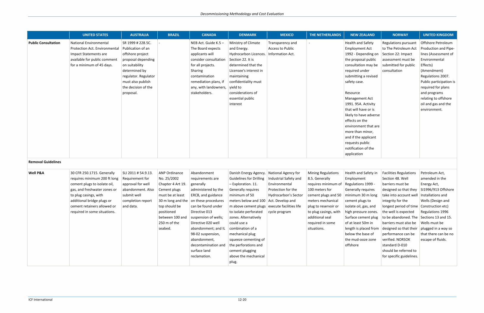
Decommissioning Methodology and Cost Evaluation
ICF International 12-20
UNITED STATES AUSTRALIA BRAZIL CANADA DENMARK MEXICO THE NETHERLANDS NEW ZEALAND NORWAY UNITED KINGDOM
Public Consultation National Environmental
Protection Act. Environmental
Impact Statements are
available for public comment
for a minimum of 45 days.
SR 1999 # 228.5C.
Publication of an
offshore project
proposal depending
on suitability
determined by
regulator. Regulator
must also publish
the decision of the
proposal.
- NEB Act. Guide K.5 –
The Board expects
applicants will
consider consultation
for all projects.
Sharing
contamination
remediation plans, if
any, with landowners,
stakeholders.
Ministry of Climate
and Energy.
Hydrocarbon Licences.
Section 22. It is
determined that the
Licensee's interest in
maintaining
confidentiality must
yield to
considerations of
essential public
interest
Transparency and
Access to Public
Information Act.
- Health and Safety
Employment Act
1992 - Depending on
the proposal public
consultation may be
required under
submitting a revised
safety case.
Resource
Management Act
1991. 95A. Activity
that will have or is
likely to have adverse
effects on the
environment that are
more than minor,
and if the applicant
requests public
notification of the
application
Regulations pursuant
to The Petroleum Act
Section 22: Impact
assessment must be
submitted for public
consultation
Offshore Petroleum
Production and Pipe-
lines (Assessment of
Environmental
Effects)
(Amendment)
Regulations 2007.
Public participation is
required for plans
and programs
relating to offshore
oil and gas and the
environment.
Removal Guidelines
Well P&A 30 CFR 250.1715. Generally
requires minimum 200 ft long
cement plugs to isolate oil,
gas, and freshwater zones or
to plug casings, with
additional bridge plugs or
cement retainers allowed or
required in some situations.
SLI 2011 # 54.9.13.
Requirement for
approval for well
abandonment. Also
submit well
completion report
and data.
ANP Ordinance
No. 25/2002
Chapter 4 Art 19.
Cement plugs
must be at least
30 m long and the
top should be
positioned
between 100 and
250 m of the
seabed.
Abandonment
requirements are
generally
administered by the
ERCB, and guidance
on these procedures
can be found under
Directive 013
suspension of wells;
Directive 020 well
abandonment; and IL
98-02 suspension,
abandonment,
decontamination and
surface land
reclamation.
Danish Energy Agency.
Guidelines for Drilling
– Exploration. 11.
Generally requires
minimum of 50
meters below and 100
m above cement plugs
to isolate perforated
zones. Alternatively
could use a
combination of a
mechanical plug
squeeze cementing of
the perforations and
cement plugging
above the mechanical
plug.
National Agency for
Industrial Safety and
Environmental
Protection for the
Hydrocarbon’s Sector
Act. Develop and
execute facilities life
cycle program
Mining Regulations
8.5. Generally
requires minimum of
100 meters for
cement plugs and 50
meters mechanical
plug to reservoir or
to plug casings, with
additional seal
required in some
situations.
Health and Safety in
Employment
Regulations 1999 -
Generally requires
minimum 30 m long
cement plugs to
isolate oil, gas, and
high pressure zones.
Surface cement plug
of at least 50m in
length is placed from
below the base of
the mud-ooze zone
offshore
Facilities Regulations
Section 48. Well
barriers must be
designed so that they
take into account well
integrity for the
longest period of time
the well is expected
to be abandoned. The
barriers must also be
designed so that their
performance can be
verified. NORSOK
standard D-010
should be referred to
for specific guidelines.
Petroleum Act,
amended in the
Energy Act,
SI1996/913 Offshore
Installations and
Wells (Design and
Construction etc)
Regulations 1996
Sections 13 and 15.
Wells must be
plugged in a way so
that there can be no
escape of fluids.

Decommissioning Methodology and Cost Evaluation
ICF International 12-21
UNITED STATES AUSTRALIA BRAZIL CANADA DENMARK MEXICO THE NETHERLANDS NEW ZEALAND NORWAY UNITED KINGDOM
Structures 30 CFR 250.1728. Platforms
and facilities must be removed
to at least 15 ft below the
mudline. Alternate depths
may be approved in some
situations.
SLI 2009 #382.2.40.
Requires an
independent
validator to cover
evaluation agreed
between NOPSEMA
and the operator.
ANP Ordinance
No. 25/2002
Chapter 4 Art 20.
In water depths
up to 80 m, all
equipment should
be removed
above the seabed
or up to 20 m
below the bottom
in areas subject to
intense erosion.
SOR/2009-315 #59.
Not specified
Offshore Safety Act
Section 56.
Dismantling must be
carried out to ensure
that the health and
safety risks are
reduced as much as
reasonably
practicable.
National Agency for
Industrial Safety and
Environmental
Protection for the
Hydrocarbon’s Sector
Act. Develop and
execute facilities life
cycle program
Mining Decree. 5.2.4.
A mining installation
located completely
below surface water
shall be equipped
with a protective
construction to
prevent damage.
- NORSOK Standard N-
001. Specific
decommissioning
standards are set
under DNV-RP-H102.
1996 No.913
The duty holder shall
ensure that an
installation is
decommissioned and
dismantled in such a
way that, so far as is
reasonably
practicable, it will
possess sufficient
integrity to enable
such
decommissioning and
dismantlement to be
carried out safely.
Location Clearance 30 CFR 250.1740. The site
must be cleared of all
obstructions. A trawl must be
dragged across the site for
water depths less than 300 ft.
For water depths greater than
300 ft, sonar equipment may
be used to ensure the site is
clear.
OPGGS Act Section
572. Imposes an
obligation on the
duty holder to
remove all
structures,
equipment and
property within the
title area.
ANP Ordinance
No. 25/2002
Chapter 4 Art 20.
In water depths
up to 80 m, all
equipment should
be removed
above the seabed
or up to 20 m
below the bottom
in areas subject to
intense erosion.
SOR/2009-315 #58.
Seafloor is of any
material or
equipment that might
interfere with other
commercial uses of
the sea.
OSPAR convention
1998. Operators
provide proposal for
location clearance
under
decommissioning
plan.
National Agency for
Industrial Safety and
Environmental
Protection for the
Hydrocarbon’s Sector
Act. Develop and
execute facilities life
cycle program
OSPAR convention
1998. Operators
provide proposal for
location clearance
under
decommissioning
plan.
Maritime Transport
Act 1994 - 388
Marine protection
rules in relation to
harmful and other
substances
NORSOK Standard D-
010 9.8.2. The
location shall be
inspected to ensure
no other obstructions
related to the drilling
and well activities are
left behind on the sea
floor.
Following removal of
debris, independent
verification survey is
required.
Undertaken post
decommissioning
environmental
seabed sampling
survey to monitor
levels of
hydrocarbons, heavy
metals and other
contaminants. Survey
strategy will have
been agreed with
DECC.
Submit copies of all
debris clearance and
survey reports to
DECC.

Decommissioning Methodology and Cost Evaluation
ICF International 12-22
UNITED STATES AUSTRALIA BRAZIL CANADA DENMARK MEXICO THE NETHERLANDS NEW ZEALAND NORWAY UNITED KINGDOM
Pipelines 30 CFR 250.1751 and 1752. A
pipeline may be
decommissioned in place after
approval by pigging and
flushing the pipeline before
filling seawater and plugging.
The pipeline must then be
buried at least 3 ft below the
seafloor or have each end
covered with protective
concrete mats. Prior to
removal, pipelines must also
be pigged and flushed.
SR 1999 # 228.5A.
Submission of an
offshore project
proposal for
decommissioning a
pipeline.
- NEB – Regulating
Pipeline
Abandonment – A
detailed Plan is
expected to be filed
with an application
for abandonment.
Flushed & capped.
DEA – Operator’s
responsibility. In case
of in-situ
decommissioning,
with appropriate
remedial work, the
pipelines will remain
operator
responsibility and will
be subject to an
agreed monitoring
program to ensure the
lines remain free of
hazards to other sea
users.
National Agency for
Industrial Safety and
Environmental
Protection for the
Hydrocarbon’s Sector
Act. Develop and
execute facilities life
cycle program
Mining Decree 6.4
Article s 103 and 104.
A decommissioned
pipeline laid on the
continental shelf
shall be left behind in
a clean and safe
condition unless,
Minister prescribes
its removal. Minister
can issue the
operator instructions
concerning the
condition in which
the pipeline is to be
left behind.
Health and Safety in
Employment
Regulations 1999.
Schedule 4 - Submit
pipeline
abandonment plan
under Safety Case
Submittal.
OSPAR Decision 98/3.
Does not prohibit the
disposal of disused
pipelines and cables
at sea. Final decisions
on the disposal of oil
and gas pipelines, are
made by the Ministry
of Petroleum and
Energy
The Pipelines Safety
Regulations 1996
Section 14. The
operator shall ensure
that the
decommissioned
pipeline is left in a
safe condition.
Temporary
Abandonment
30 CFR 250.1721. Generally a
100-ft bridge or cement plug
must be set. An application to
modify must be submitted
prior to temporary
abandonment.
- ANP Ordinance
No. 25/2002
Chapter 5 Art 25.
Cement plugs or
buffer must be at
least 30 m long
and the top
should be
positioned
between 100 and
250 m of the
seabed.
SOR/2009-315 #56.
Provides isolation of
all hydrocarbon
bearing and discrete
pressure zones, and
prevents any
formation fluid from
flowing through or
escaping from the
well-bore
Danish Energy Agency.
Guidelines for Drilling
– Exploration. 11.
Generally requires
minimum of 50
meters below and 100
m above cement plugs
to isolate perforated
zones. Alternatively
could use a
combination of a
mechanical plug
squeeze cementing of
the perforations and
cement plugging
above the mechanical
plug.
- - - Facilities Regulations
Section 48. Well
barriers must be
designed so that they
take into account well
integrity for the
longest period of time
the well is expected
to be abandoned. The
barriers must also be
designed so that their
performance can be
verified. NORSOK
standard D-010
should be referred to
for specific guidelines.
Petroleum Act,
amended in the
Energy Act,
SI1996/913 Offshore
Installations and
Wells (Design and
Construction etc)
Regulations 1996
Sections 13 and 15.
Wells must be
plugged in a way so
that there can be no
escape of fluids.

Decommissioning Methodology and Cost Evaluation
ICF International 12-23
UNITED STATES AUSTRALIA BRAZIL CANADA DENMARK MEXICO THE NETHERLANDS NEW ZEALAND NORWAY UNITED KINGDOM
Removal (Partial/Full,
Full Only, Artificial
Reefs)
30 CFR 250.1730. Partial
removal or toppling in place
may be allowed if the
structure becomes part of a
State artificial reef program
and the structure satisfied the
USCG navigational
requirements.
The Environment
Protection (Sea
Dumping) Act 10E.
Artificial reefs
cannot be placed
without a proper
permit.
ANP Ordinance
No. 25/2002
Chapter 4 Art 20.
In water depths
up to 80 m, all
equipment should
be removed
above the seabed
or up to 20 m
below the bottom
in areas subject to
intense erosion.
SOR/96-118 #43.
Where the removal of
a fixed offshore
production
installation is a
condition of a
development plan
approval, the
operator shall
incorporate in the
design of the
installation such
measures as are
necessary to facilitate
its removal from the
site without causing a
significant effect on
navigation or the
marine environment.
OSPAR Decision 98/3.
Requires complete
removal.
National Agency for
Industrial Safety and
Environmental
Protection for the
Hydrocarbon’s Sector
Act. Develop and
execute facilities life
cycle program
Mining Decree 5.1.4
Article 39: Partial or
full removal is
allowed, and must be
specified in removal
plan
Health and Safety in
Employment
Regulations 1999.
Schedule 4 - Submit
decommissioning
proposal for
demolishing or
dismantling plan
under Safety Case
Submittal.
Need Environmental
Protection Authority
ruling when alter,
extend, remove, or
demolish an existing
structure or existing
submarine pipeline
associated with an
activity.
OSPAR Decision 98/3.
Requires complete
removal (may be
possible to request
waiver for large
structures).
NORSOK standard Z-
013. Risk analysis
assessment will be
needed for final
disposal of an
installation.
OSPAR Decision 98/3.
Requires complete
removal (may be
possible to request
waiver for large
structures).
Material Disposal 30 CFR 250.1726. Platform or
other facility disposal plans
must be submitted during
initial removal application.
The Environment
Protection (Sea
Dumping) Act 10B,
10C, 10D. Operators
may not dispose of
materials without
the required
permits.
Ordinance
422/2001. An EIA
must be prepared
for offshore oil
and gas activities.
Specificity of the
EIA will vary
depending on the
sensitivity of the
area being
developed.
SOR/2009-315 #6.
Submit application for
authorization with a
description of
equipment and
procedures
Chemical Substances
and Products Act. Soil
Contamination Act.
Environmental
Liability Act.
Waste is regulated in
integrated
environmental
permits by
Environmental
Protection Agency.
Special Rules -
Statutory order no.
1502 of 2004,
Consolidated Act no.
1072 of 2010,
Directive 2012/19/EU,
& Directive
2000/53/EC.
National Agency for
Industrial Safety and
Environmental
Protection for the
Hydrocarbon’s Sector
Act. “Secondary Laws”
of Energy Reform
2014, created National
Agency for Industrial
Safety and
Environmental
Protection, which will
grant environmental
impact authorization.
Mining Decree 5.2.3
Article 62: Operator
must submit data
detailing how the
material was
disposed.
Maritime Transport
Act 1994 – Submit
request to
Environmental
Protection Authority
The Petroleum Act
Section 5.3: The
Ministry will
determine the
appropriate disposal
method and the time
frame in which the
operator must carry it
out. The operator is
then responsible for
ensuring that disposal
is carried out as
directed.
Section 44: Provides
specific requirements
for decommissioning
plan’s Disposal.
Petroleum Act 1998
(Guidance Notes).
Platform or other
facility disposal plans
must be submitted
with
decommissioning
programme.
Environmental

Decommissioning Methodology and Cost Evaluation
ICF International 12-24
UNITED STATES AUSTRALIA BRAZIL CANADA DENMARK MEXICO THE NETHERLANDS NEW ZEALAND NORWAY UNITED KINGDOM
Spill Response 30 CFR 250. Oil-Spill Response
Plans must demonstrate that
the operators can respond
quickly and effectively when
oil is discharged from the
facility. The plan must be
submitted prior the facility
being used.
SR 1999 #223.
Submit a summary
of the response
arrangements in the
oil pollution
emergency plan
under
environmental plan.
Ordinance
422/2001. An EIA
must be prepared
for offshore oil
and gas activities.
Specificity of the
EIA will vary
depending on the
sensitivity of the
area being
developed.
SOR/2009-315 #6.
Submit application for
authorization with a
contingency plans,
including emergency
response procedures,
to mitigate the effects
of any reasonably
foreseeable event
that might
compromise safety or
environmental
protection
Statutory Order on
Preparedness in Case
of Pollution from
Certain Facilities at
Sea. Offshore
operators are
required to develop
Oil and Chemical Spill
Contingency Plans.
The plan needs to be
updated and re-
approved as activities
change.
Hydrocarbon Laws
Article 47. Spills are
liability of operator.
Mining Decree
Disaster control plan
- In agreement with
Minister rules shall
be set by ministerial
regulation
concerning the use of
certain substances or
preparations on a
mining installation in
order to prevent
pollution of surface
water.
Maritime Transport
Act Part 23. Oil spill
response strategies
must be prepared
and kept on file, with
reviews at least every
5 years.
Pollution Control Act
Sections 49 and 51.
Studies required to
map-out the risk of
pollution in
connection with and
following
decommissioning
operations.
The Merchant
Shipping (Oil
Pollution
Preparedness,
Response and Co-
operation
Convention)
Regulations 1998
Section 4. Offshore
operators must have
an oil pollution
emergency plan in
place prior to any
activities are
commenced.
Environmental Liability
Specification
30 CFR 553. Oil Spill Financial
Responsibility (OSFR) for
covered offshore facilities is
dependent on the worst case
oil-spill discharge volume,
varying from $10,000,000 to
$150,000,000. (Also see
financial assurance)
The Environment
Protection (Sea
Dumping) Act 10A,
10B, 10C, 10D, 10E,
and 16. Improper
disposal, placement
of a reef, or harm to
the environment will
result in penalties.
Concession
Agreement Clause
21. The operator
is liable for all
damages and
losses to the
environment,
which may result
in fines and/or
penalties.
Oil and Gas Spills and
Debris Liability
Regulations. Provides
the financial liability
for oil and gas related
spills. Amounts vary
by area and size of the
spill.
Danish Merchant
Shipping Act Section
175 and Order No.
838. Financial liability
for oil pollution
damage varies by ship
size and extent of
damage.
Hydrocarbons Law
Article 122. The
Operator will carry out
actions for the
prevention and
remediation of
damages to the
environment or the
ecological balance
caused by their
activities, and shall be
required to bear the
costs involved in the
remediation.
Environmental
Liability Directive
2004. Framework
based on the polluter
pays principle to
prevent and remedy
environmental
damage.
Mining Decree 8.2.
Article 121. Capitol of
at least €250,000
fund is required by
the operators.
Maritime Transport
Act 1994 - Operators
are liable for any
incidents that might
occur during the
disposal process.
Part 102 applies a
fixed minimum
requirement for all
offshore installations,
irrespective of the
operation’s type,
possible risk, or the
potential impact of a
spill. The minimum is
currently set at 14
million International
Monetary Fund Units
of Account, or
approximately NZ$26
million
The Petroleum Act
Section 5.4 and
Regulations pursuant
to the Petroleum Act
Section 45A:
Operators are liable
for any incidents that
might occur during
the disposal process
The Merchant
Shipping (Oil
Pollution
Preparedness,
Response and Co-
operation
Convention)
Regulations 1998
Section 7. Oil
pollution offenses
will be punishable by
a fine not exceeding
the statutory
maximum.
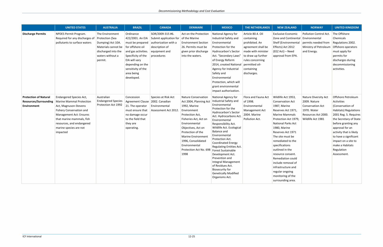
Decommissioning Methodology and Cost Evaluation
ICF International 12-25
UNITED STATES AUSTRALIA BRAZIL CANADA DENMARK MEXICO THE NETHERLANDS NEW ZEALAND NORWAY UNITED KINGDOM
Discharge Permits NPDES Permit Program.
Required for any discharges of
pollutants to surface waters
The Environment
Protection (Sea
Dumping) Act 10A.
Materials cannot be
discharged into the
waters without a
permit.
Ordinance
422/2001. An EIA
must be prepared
for offshore oil
and gas activities.
Specificity of the
EIA will vary
depending on the
sensitivity of the
area being
developed.
SOR/2009-315 #6.
Submit application for
authorization with a
description of
equipment and
procedures
Act on the Protection
of the Marine
Environment Section
26. Permits must be
given prior discharge
into the waters.
National Agency for
Industrial Safety and
Environmental
Protection for the
Hydrocarbon’s Sector
Act. “Secondary Laws”
of Energy Reform
2014, created National
Agency for Industrial
Safety and
Environmental
Protection, which will
grant environmental
impact authorization.
Article 80.4. Oil
containing
prohibited. An
agreement shall be
made with minister
to draw up further
rules concerning
permitted oil-
containing
discharges.
Exclusive Economic
Zone and Continental
Shelf (Environmental
Effects) Act 2012
(EEZ Act) – Need
approval from EPA.
Pollution Control Act.
Environmental
permits needed from
Ministry of Petroleum
and Energy.
The Offshore
Chemicals
Regulations 2002.
Offshore operators
must apply for
permits for
discharges during
decommissioning
activities.
Protection of Natural
Resources/Surrounding
Environment
Endangered Species Act,
Marine Mammal Protection
Act, Magnuson-Stevens
Fishery Conservation and
Management Act: Ensures
that marine mammals, fish
resources, and endangered
marine species are not
impacted
Australian Endangered Species Protection Act 1992
Concession
Agreement Clause
21. The operator
must ensure that
no damage occur
to the field that
they are
operating.
Species at Risk Act
2002. Canadian
Environmental
Assessment Act 2012.
Nature Conservation
Act 2004, Planning Act
1992, Marine
Environment
Protection Act,
Fisheries Act, Act on
Environmental
Objectives, Act on
Protection of the
Marine Environment
1996, Consolidated
Environmental
Protection Act No. 698
1998
National Agency for Industrial Safety and Environmental Protection for the Hydrocarbon’s Sector Act. Hydrocarbons Act. Environmental Responsibility Act. Wildlife Act. Ecological Balance and Environmental Protection Act. Coordinated Energy Regulating Entities Act. Forest Sustainable Development Act. Prevention and Integral Management of Residues Act. Biosecurity for Genetically Modified Organisms Act.
Flora and Fauna Act
of 1998.
Environmental
Management Act
2004. Marine
Pollution Act.
Wildlife Act 1953,
Conservation Act
1987, Marine
Reserves Act 1971,
Marine Mammals
Protection Act 1979,
National Parks Act
1980, Marine
Reserves Act 1971
The site must be
remediated to the
specifications
outlined in the
resource consent.
Remediation could
include removal of
infrastructure and
regular ongoing
monitoring of the
surrounding area.
Nature Diversity Act
2009. Nature
Conservation Act
1970. Water
Resources Act 2000.
Wildlife Act 1981
Offshore Petroleum
Activities
(Conservation of
Habitats) Regulations
2001 Reg. 5. Requires
the Secretary of State
before granting any
approval for an
activity that is likely
to have a significant
impact on a site to
make a Habitats
Regulation
Assessment.

Decommissioning Methodology and Cost Evaluation
ICF International 12-26
UNITED STATES AUSTRALIA BRAZIL CANADA DENMARK MEXICO THE NETHERLANDS NEW ZEALAND NORWAY UNITED KINGDOM
Environmental
Inspection
BSEE IIPD 2012-03. BSEE will
conduct scheduled and
unannounced inspections to
verify compliance with all
environmental laws and
regulations, lease stipulations,
mitigation measures,
conditions of approval, and
other environmental
requirements.
Offshore Petroleum
and Greenhouse Gas
Storage Act 2006
and Offshore
Petroleum and
Greenhouse Gas
Storage
(Environment)
Regulations 2009
(Environment
Regulations). An
environmental
inspection program,
applied with risk-
based methodology.
Ordinance
422/2001. An EIA
must be prepared
for offshore oil
and gas activities.
Specificity of the
EIA will vary
depending on the
sensitivity of the
area being
developed.
Canada – Nova Scotia
Offshore marine
installations and
structures
occupational health
and safety transitional
regulations – Safety
device tested by the
operator once every
12 months, records
maintained for 5
years.
Danish Energy Agency.
Guidelines for Drilling
- 6. During inspection,
inspectors from the
Danish Energy Agency
may in consultation
with the operator
require drills for
emergency
preparedness.
DEA carries out
Regular and
unannounced
inspections.
National Agency for
Industrial Safety and
Environmental
Protection for the
Hydrocarbon’s Sector
Act. “Secondary Laws”
of Energy Reform
2014, created National
Agency for Industrial
Safety and
Environmental
Protection, which will
grant environmental
impact authorization.
Mining Decree 5.2.1
Article 53: The
operator shall
periodically check the
technical integrity of
a mining installation
designated for
production or
storage. The
operator shall draw
up a checking
programme for this
purpose every 5
years.
Monitoring and
compliance will be
carried out by New
Zealand Petroleum &
Minerals (NZP&M),
Environmental
Protection Authority
(EPA), and WorkSafe
New Zealand.
The Petroleum Act.
Announced
inspections.
The Merchant
Shipping (Oil
Pollution
Preparedness,
Response and Co-
operation
Convention)
Regulations 1998
Section 8. The
Secretary of State
may authorize
inspections of
offshore installations
at any time to ensure
compliance with oil
pollution
preparedness.
Health and Safety
Decommissioning
Specific Employee
Health and Safety
SLI 2009 #382.2.30.
Submit revision of a
safety case because
of a change of
circumstances or
operations.
Canada – Nova Scotia
Offshore marine
installations and
structures
occupational health
and safety transitional
regulations – A
management system
must be in place for
health and safety
during dismantling
activities.
The Offshore Safety
Act Sections 19 and
23. A management
system must be in
place for health and
safety during
dismantling activities.
A health and safety
case will need to be
updated for
dismantling activities
once the procedure is
determined.
The general rules of
the Working
Conditions Act are
elaborated upon in
the Working
Conditions Decree
and the Working
Conditions
Regulation. Few of
the specifics under
Mining Decree are
decommissioning
focused.
Working Conditions
Decree – Submit
Health and Safety
Document with Risk
Identification,
evaluation,
elimination and
reduction, and
management.
PSA supervises the
safety during all
phases of the
decommissioning
process until the
installation is placed
onto a vessel. The
Municipal Authority
carries responsibility
for supervision at the
demolition yard.
Offshore Installations
(Safety Case)
Regulations 2005. An
Abandonment Safety
Case is required prior
to any
decommissioning
activities.
*DISCLAIMER – The blanks in the table entails that regulation was not found with the resources that were allocated to the project.

Decommissioning Methodology and Cost Evaluation
ICF International 12-27
12.5. Regulatory Gaps
Based on the Regulatory Matrix, US Federal requirements cover most of the requirements noted in
regulations around the world. The US requirements seem to be fairly strong in providing definitive
removal guidance, which many of the other countries are lacking.
The United Kingdom allows the Secretary of State to provide modifications to a decommission plan or
application during the approval process, instead of just approving or rejecting an application as it is
written. The US requirements do not specify an allowance for modifications in the approval process.
Although the US tends to have more specific and detailed removal guidance than other countries,
Norway and the United Kingdom utilize and reference industry developed guidance documents to cover
the specifics. These guidance documents and standards provide a level of detail that is not captured in
the US regulatory requirements.
Norway, the United Kingdom, Denmark, and draft Thailand Regulations have decommissioning specific
health and safety requirements. Norway, for example, specifies who is responsible for ensuring safe
practices at each stage of the material disposal process. The US, while having health and safety activities
regulated under OSHA, does not have any requirements called out specifically for decommissioning
related activities.
12.6. Suggested Modifications
Including provisions that allow the reviewer of a decommissioning or removal plan to include
modifications in their approval could help ensure that the removal action is being done in the exact
manner BSEE requires, without requiring too much back and forth by rejecting and requiring the
operator to submit a new plan.
BSEE might consider utilizing guidance references in removal regulations, similar to what is done in the
United Kingdom and Norway, in order to include additional detail in the requirements. This would guide
operators referencing the regulations for their removal operations to guidance documents that contain
best practices and detailed information on how they should carry out their decommissioning operations.
Decommissioning-specific health and safety requirements would be helpful in ensuring that operators
consider the health and safety risks of decommissioning operations and help reduce the number of
incidents associated with such operations. Current regulations require decommissioning plans to include
environmental impacts, but do not require that the operator explicitly consider health and safety risks.
BSEE should consider the potential for the submission of actual decommissioning cost data to confirm or
to improve the reliability of decommissioning cost estimates provided for the determination of the
amount of financial assurance required. In the UK, the close-out report includes actual decommissioning
cost information.

Decommissioning Methodology and Cost Evaluation
ICF International 12-28
Planning decommissioning projects requires a review of the design and operational records of the
offshore facilities need to be reviewed during. If the operator has a complete set of documents to
review, there are fewer uncertainties associated with a decommissioning project and a higher likelihood
of successful execution. This is a challenge as some of the platforms change operators many times. BSEE
may consider instituting a records retention requirement so that this information is retained by the
operator and passed to another operator at the time of transfer of the asset. Some of the key
documents include:
Well completion documents and details of all well work performed. It is critical that all known
wellbore problems (tubing obstructions, casing pressure and mechanical integrity issues) be
documented.
Complete original structural drawings including all structural modifications performed after the
platform was installed
As built pipeline survey maps
Platform installation procedures including lifting weights of the major platform components
Details of significant equipment removal and additions since the platform was installed
Platform crane load charts and the most recent crane inspection report which will determine if the
crane could be useful during decommissioning work.
Underwater inspection reports of the platform, pipelines and subsea systems
Report to indicate if the platform rig and living quarters are useable for platform abandonment work