declaration of - master hire · pump coalescer (far side) priming tank air filter control panel...
TRANSCRIPT

DECLARATION OF CONFORMITY
Our policy is one of continuous improvement and we reserve the right to alter specifications at any time Page 2 of 22
We SPP Pumps Limited Of Theale Cross Reading Berkshire England RG31 7SP
2000/14/EC – Guaranteed sound power level The conformity assessment procedure followed was in according with ANNEX V of the Directive.
Declare that:
Category: WATER PUMP UNIT Equipment: MOBILE DIESEL DRIVEN CENTRIFUGAL PUMPS
Model/Type: QI100, QC100, QP100, QI100MM, QC100MM, QP100MM, QI150, QC150, QP150,
QI150M, QC150M, QP150M, QI200, QC200, QP200, QIHH80, QCHH80 & QPHH80.
Serial Number: As shown on the Pump Nameplate
in accordance with the following Directives:
2004/108/EC The Electromagnetic Compatibility Directive and its amending directives
2006/42/EC The Machinery Directive and its amending directives
2000/14/EC The Noise Emissions Directive and its amending directives
have been designed and manufactured to the following specifications:
EN 809:1998+A1:2009 Pump and pump unit for liquids – common safety requirements EN 12162: 2001 Liquid pumps – Safety requirements – Proceedure for hydrostatic
testing. EN 292-2: 1991 Safety of Machinery- Basic concepts, general principles for design.
EN 61000-6-4: 2001 Electromagnetic compatibility (EMC). Generic standards. Emission standard for industrial environment.
EN 61000-6-1: 2001 Electromagnetic compatibility (EMC). Generic standards. Immunity for residential, commercial and light-industrial environments.
EN 3744: 1995 Acoustics- Determination of sound power levels of noise sources using sound pressure- Engineering method in an essentially free field over a reflecting plane
We hereby declare that the equipment named above has been designed to comply with the relevant sections of the above referenced specifications. The units comply with all essential requirements of the Directives.
Signed:
Name: John Hollins
Position: Engineering Manager - Authorised to sign on behalf of SPP Pumps Limited
Mushet Industrial Park, Coleford, Gloucestershire, England, GL16 8PS
Date: 6 June 2011
W72-018E
A copy of this certificate has been submitted to the European Commission and UK Authority
Sound Level (dB) Pump Model Measured Guaranteed LW A
QI100 93.5 96
QC/QP100 94.2 97
QI100MM 94.5 97
QC/QP100MM 94.5 97
QI150 94.7 97
QC/QP150 94.5 97
QI150M 98.1 101
QC/QP150M 94.5 97
QI200 94.2 97
QC/QP200 94.5 97
QHH80 101.6 106
Operators Instructions for Q Range Diesel Driven Centrifugal Pumps
Manual No/Rev W72-018E / 9
Our policy is one of continuous improvement and we reserve the right to alter specifications at any time Page 3 of 22
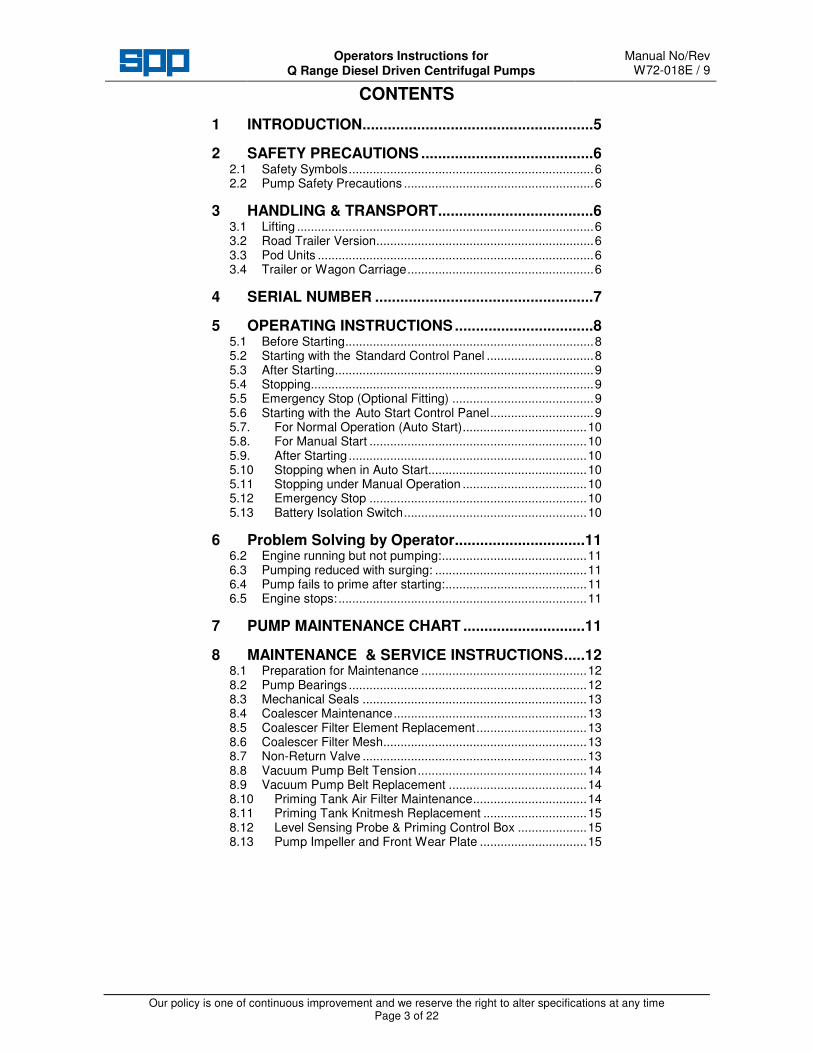
CONTENTS
1 INTRODUCTION.......................................................5
2 SAFETY PRECAUTIONS .........................................6 2.1 Safety Symbols.......................................................................6 2.2 Pump Safety Precautions .......................................................6
3 HANDLING & TRANSPORT.....................................6 3.1 Lifting ......................................................................................6 3.2 Road Trailer Version...............................................................6 3.3 Pod Units ................................................................................6 3.4 Trailer or Wagon Carriage......................................................6
4 SERIAL NUMBER ....................................................7
5 OPERATING INSTRUCTIONS.................................8 5.1 Before Starting........................................................................8 5.2 Starting with the Standard Control Panel ...............................8 5.3 After Starting...........................................................................9 5.4 Stopping..................................................................................9 5.5 Emergency Stop (Optional Fitting) .........................................9 5.6 Starting with the Auto Start Control Panel..............................9 5.7. For Normal Operation (Auto Start)....................................10 5.8. For Manual Start ...............................................................10 5.9. After Starting .....................................................................10 5.10 Stopping when in Auto Start..............................................10 5.11 Stopping under Manual Operation ....................................10 5.12 Emergency Stop ...............................................................10 5.13 Battery Isolation Switch.....................................................10
6 Problem Solving by Operator...............................11 6.2 Engine running but not pumping:..........................................11 6.3 Pumping reduced with surging: ............................................11 6.4 Pump fails to prime after starting:.........................................11 6.5 Engine stops: ........................................................................11
7 PUMP MAINTENANCE CHART .............................11
8 MAINTENANCE & SERVICE INSTRUCTIONS.....12 8.1 Preparation for Maintenance ................................................12 8.2 Pump Bearings .....................................................................12 8.3 Mechanical Seals .................................................................13 8.4 Coalescer Maintenance........................................................13 8.5 Coalescer Filter Element Replacement................................13 8.6 Coalescer Filter Mesh...........................................................13 8.7 Non-Return Valve .................................................................13 8.8 Vacuum Pump Belt Tension.................................................14 8.9 Vacuum Pump Belt Replacement ........................................14 8.10 Priming Tank Air Filter Maintenance.................................14 8.11 Priming Tank Knitmesh Replacement ..............................15 8.12 Level Sensing Probe & Priming Control Box ....................15 8.13 Pump Impeller and Front Wear Plate ...............................15

Operators Instructions for Q Range Diesel Driven Pump Units
Manual No/Rev W72-018E / 9
Our policy is one of continuous improvement and we reserve the right to alter specifications at any time
Page 4 of 22
9 PUMP FAULT FINDING .........................................16 9.2 Checking the operation of the priming system .....................16 9.3 Check the vacuum pump drive belts ....................................16 9.4 Check the vacuum pump clutch ...........................................16 9.5 Check the solenoid valve......................................................16 9.6 Priming filter blockage. .........................................................16 9.7 Priming tank knitmesh filter blocked.....................................16 9.8 Volute non return valve not sealing ......................................16 9.9 Air leak in priming system.....................................................17 9.10 Vacuum pump...................................................................17 9.11 Fault Finding Guide...........................................................17
10 TECHNICAL DATA.................................................18 10.1 Engine Specific Data.........................................................18 10.2 General Data.....................................................................19 10.3 General Arrangements .....................................................20
11 SPARES & SERVICE .............................................22
12 ENGINE OPERATORS HANDBOOK.....................22

Operators Instructions for AUTOPRIME Q Range Pump Unit
Manual No/Rev W72-008E / 9
Our policy is one of continuous improvement and we reserve the right to alter specifications at any time Page 5 of 22
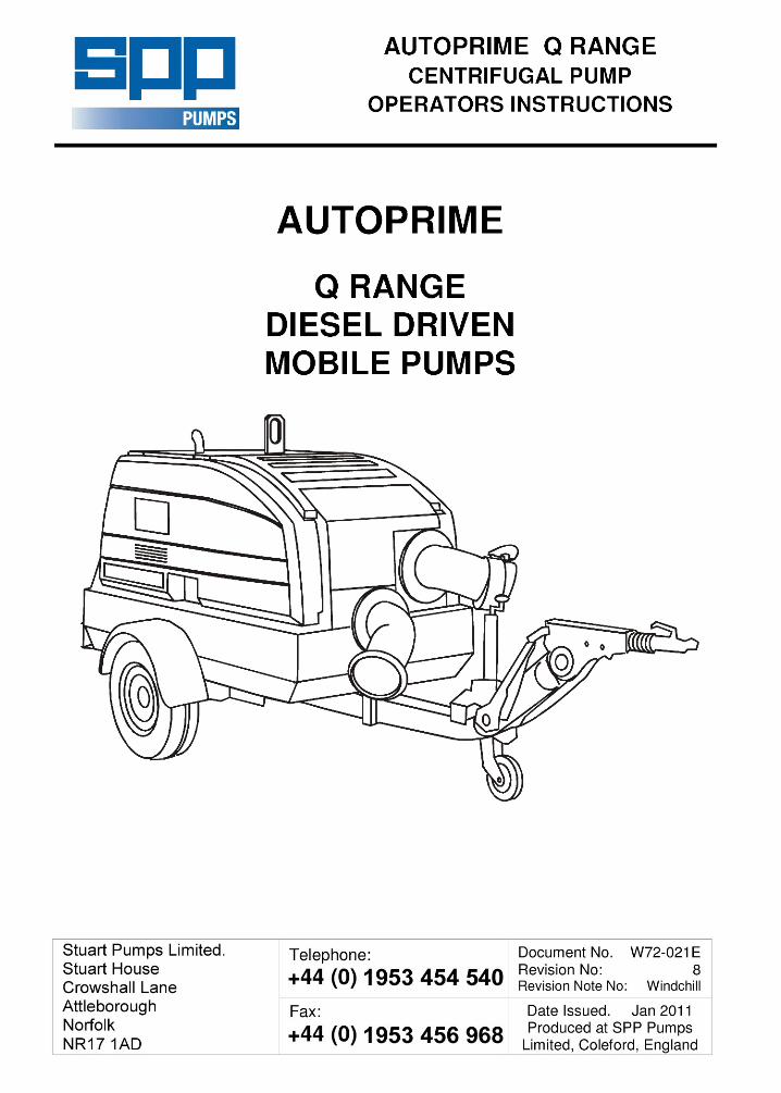
1 INTRODUCTION
The purpose of this handbook is to provide operating guidelines and routine maintenance instructions for the SPP AUTOPRIME Q Range of bunded diesel engine driven pumps, featuring the electric priming system (SMARTprime).
Instructions and statements contained within this handbook are given with our best intentions and are correct at the time of compilation. They are subject to alteration at any time.
These pumps are most commonly supplied mounted on 2 wheel road trailers but can also be supplied on site trailers, skid mounted, or as a pod unit for customer’s to mount on a suitable chassis or foundations. This Handbook covers the following pumps:
Q 100 – 4” automatic priming mobile pump driven by an Isuzu 3CE1 (QI), CAT C1.5 (QC) or a Perkins 403D-15 (QP) diesel engine mounted in a bunded and sound reducing canopy.
Q 150 – 6” automatic priming mobile pump driven by an Isuzu 3CE1 (QI), CAT C1.5 (QC) or a Perkins 403D-15 (QP) diesel engine mounted in a bunded and sound reducing canopy. Q100MM – 4” automatic priming mobile pump driven by an Isuzu 4LE1 (QI), CAT C2.2 (QC) or Perkins 404D-22 (QP) diesel engine mounted in a bunded and sound reducing canopy.
Q 150M – 6” automatic priming mobile pump driven by an Isuzu 4LE1 (QI), CAT C2.2 (QC) or Perkins 404D-22 (QP) diesel engine mounted in a bunded and sound reducing canopy.
QC 200 – 8” automatic priming mobile pump driven by an Isuzu 4LE1 (QI), CAT C2.2 (QC) or Perkins 404D-22 (QP) diesel engine mounted in a bunded and sound reducing canopy. QHH80 – 3” automatic priming, high head mobile pump driven by an Isuzu 4LE1 (QI), CAT C2.2 (QC) or Perkins 404D-22 (QP) diesel engine mounted in a bunded and sound reducing canopy.
VACUUM PUMP
COALESCER(far side)
PRIMING TANKAIR FILTER
CONTROLPANEL
RADIATORFILLER CAP
EXHAUSTSILENCER
FRONT PANEL
VACUUM PUMPDRIVE BELTAND CLUTCH
PRIMINGTANK
DRIVE ENDSHAFT BEARING
FUELFILLER
PUMP ENDSHAFT BEARINGS
SUCTIONFLANGE
DELIVERYFLANGE
NON RETURNVALVE
UNITLIFTER
VOLUTE
SOLENOIDVALVE
MECHANICALSEAL OILRESERVOIR
Q Range Pump Components

Manual No/Rev W72-018E / 9
Operators Instructions for Q Range Diesel Driven Centrifugal Pumps
Our policy is one of continuous improvement and we reserve the right to alter specifications at any time Page 6 of 22
2 SAFETY PRECAUTIONS 2.1 Safety Symbols
Safety instructions within this manual are marked with the following symbols:
This symbol refers to general mechanical aspects of safety.
This symbol refers to electrical safety.
This symbol gives warning of a hazard to the pump itself, which in turn could cause a risk to personal safety.
2.2 Pump Safety Precautions
apply to all the following:-
1. This pump contains exposed moving parts
and hot surfaces DO NOT OPERATE THE PUMP WITH THE DOORS OPEN. Guards removed for maintenance must be replaced before starting the pump.
2. These pumps may be fitted with automatic
start and stop control by high and low level float switches. When the unit is not running the pump may start without warning, switch off the key-switch or disconnect the high level start float switch before doing any checks or maintenance inside the enclosure
3. Never insert anything into the pump casing
whilst the pump is running and the suction and delivery hoses are disconnected.
4. Never use collapsible hoses on the suction side of the pump and use all pump flange holes to fit suction and delivery hose connections.
5. Always lift pump sets vertically by the lifting eye. Any side force will damage the lifter. Never lift with suction or delivery hoses attached. The increased weight of these items may cause lifting gear failure.
6. Check the type of liquid being pumped
before working on pump ends. Residues could be hazardous to your health. If in doubt flush out with clean water before work commences.
7. Personnel working on the pump unit must
always wear clean correctly fitting clothing and safety footwear. Clothing impregnated with oil or fuel can constitute a health hazard through prolonged contact with the skin and may also constitute a fire hazard.
8. Always allow adequate ventilation for diesel engines. Be aware of fire risks from items such as exhaust pipes and silencers. Never place flammable items around the unit.
3 HANDLING & TRANSPORT 3.1 Lifting
The central lifting point is designed for lifting only the bare pump unit (pod) and two-wheel road trailer mounted pumps as supplied by SPP Pumps Limited. Due to the additional weight of skid-mounted units, these are provided with alternative lifting points and fork truck slots on the skid.
Do not use the central lifter to lift skid-mounted units, or units that have been mounted on general purpose flat bed trailers.
The central lifter is suitable only for vertical lifting and must not be used to pull the unit sideways. Before lifting ensure that the lifting point is not bent or damaged. Do NOT use a lift truck with forks under the fuel tank and do NOT lift with the hoses attached.
3.2 Road Trailer Version
Lighting equipment is provided to suit customer requirements and to comply with national lighting regulations.
3.3 Pod Units
All pod units have provision for lifting from a central lifting point through the canopy. The pod unit must be fastened securely to a suitable frame that is located on firm level foundations. For details of attachment points provided for pod units, refer to SPP Pumps Limited or to the Pod General Arrangement drawing.
3.4 Trailer or Wagon Carriage
Transportation on a trailer or wagon will require the unit to be strapped down. On the road trailer mounted units, set the unit level with the rear prop stand and jockey wheel, straps can then be fitted directly across the trailer bar in front of the pump and through the security bolt located centrally under the chassis at the rear.
Under no circumstances should straps be passed over the top of the canopy or around the doors.
ATTENTION
ATTENTION

Operators Instructions for Q Range Diesel Driven Centrifugal Pumps
Manual No/Rev W72-018E / 9
Our policy is one of continuous improvement and we reserve the right to alter specifications at any time Page 7 of 22
4 SERIAL NUMBER The serial number plate is fitted inside the control panel door.
This serial number must be quoted in any enquiry for spares or service. Where required, a trailer registration plate is fitted to the front of the unit as required by local regulations and the VIN number is stamped inside the canopy frame.
Ty
Ne
Serial No.
kg
SPP Pumps Limited
Reading R 31 7SPENGLAND
G
Tel: ++44(0)1189 323123Fax: ++44(0)1189 323302
Manual No/Rev W72-018E / 9
Operators Instructions for Q Range Diesel Driven Centrifugal Pumps
Our policy is one of continuous improvement and we reserve the right to alter specifications at any time Page 8 of 22
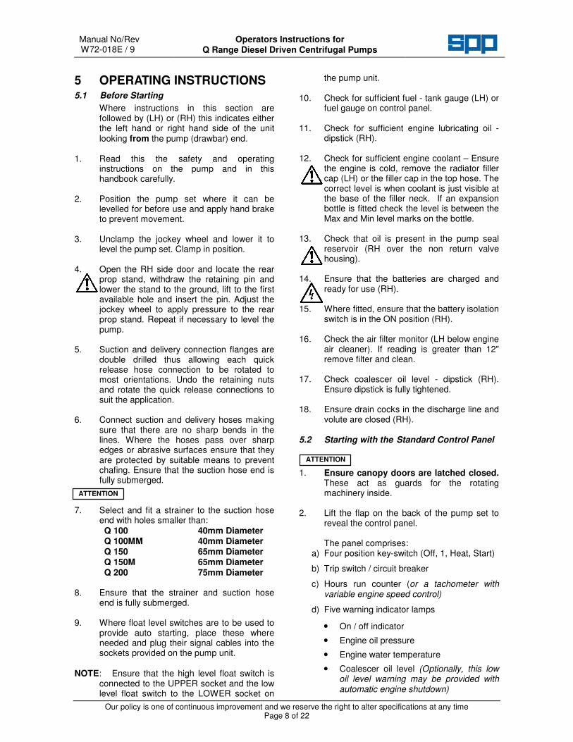
5 OPERATING INSTRUCTIONS 5.1 Before Starting
Where instructions in this section are followed by (LH) or (RH) this indicates either the left hand or right hand side of the unit looking from the pump (drawbar) end.
1. Read this the safety and operating
instructions on the pump and in this handbook carefully.
2. Position the pump set where it can be
levelled for before use and apply hand brake to prevent movement.
3. Unclamp the jockey wheel and lower it to
level the pump set. Clamp in position. 4. Open the RH side door and locate the rear
prop stand, withdraw the retaining pin and lower the stand to the ground, lift to the first available hole and insert the pin. Adjust the jockey wheel to apply pressure to the rear prop stand. Repeat if necessary to level the pump.
5. Suction and delivery connection flanges are
double drilled thus allowing each quick release hose connection to be rotated to most orientations. Undo the retaining nuts and rotate the quick release connections to suit the application.
6. Connect suction and delivery hoses making
sure that there are no sharp bends in the lines. Where the hoses pass over sharp edges or abrasive surfaces ensure that they are protected by suitable means to prevent chafing. Ensure that the suction hose end is fully submerged.
7. Select and fit a strainer to the suction hose
end with holes smaller than: Q 100 40mm Diameter Q 100MM 40mm Diameter Q 150 65mm Diameter Q 150M 65mm Diameter Q 200 75mm Diameter
8. Ensure that the strainer and suction hose
end is fully submerged. 9. Where float level switches are to be used to
provide auto starting, place these where needed and plug their signal cables into the sockets provided on the pump unit.
NOTE: Ensure that the high level float switch is
connected to the UPPER socket and the low level float switch to the LOWER socket on
the pump unit. 10. Check for sufficient fuel - tank gauge (LH) or
fuel gauge on control panel. 11. Check for sufficient engine lubricating oil -
dipstick (RH). 12. Check for sufficient engine coolant – Ensure
the engine is cold, remove the radiator filler cap (LH) or the filler cap in the top hose. The correct level is when coolant is just visible at the base of the filler neck. If an expansion bottle is fitted check the level is between the Max and Min level marks on the bottle.
13. Check that oil is present in the pump seal
reservoir (RH over the non return valve housing).
14. Ensure that the batteries are charged and
ready for use (RH). 15. Where fitted, ensure that the battery isolation
switch is in the ON position (RH). 16. Check the air filter monitor (LH below engine
air cleaner). If reading is greater than 12" remove filter and clean.
17. Check coalescer oil level - dipstick (RH).
Ensure dipstick is fully tightened. 18. Ensure drain cocks in the discharge line and
volute are closed (RH). 5.2 Starting with the Standard Control Panel
1. Ensure canopy doors are latched closed.
These act as guards for the rotating machinery inside.
2. Lift the flap on the back of the pump set to
reveal the control panel.
The panel comprises: a) Four position key-switch (Off, 1, Heat, Start)
b) Trip switch / circuit breaker
c) Hours run counter (or a tachometer with variable engine speed control)
d) Five warning indicator lamps
• On / off indicator
• Engine oil pressure
• Engine water temperature
• Coalescer oil level (Optionally, this low oil level warning may be provided with automatic engine shutdown)
ATTENTION
ATTENTION

Operators Instructions for Q Range Diesel Driven Centrifugal Pumps
Manual No/Rev W72-018E / 9
Our policy is one of continuous improvement and we reserve the right to alter specifications at any time Page 9 of 22
• Battery Charge
Standard Control Panel with Option of Tachometer and Speed Control
THEALE CROSS READINGBERKSHIRE ENGLAND
RG31 7SPTel: +44 (0)118 932 3123Fax: +44 (0)118 932 3302
SPP PUMPS LIMITED.
START/STOPKEYSWITCH
HOURS RUNMETER
OPTIONAL TACHOMETERAND VARIABLE SPEED CONTROL
TRIPSWITCH
WARNING INDICATOR LAMPS
ON OROFF
ENGINE OIL PRESSURE
ENGINE WATERTEMPERATURE
BATTERYCHARGE
COALESCEROIL LEVEL
3. Turn the ignition switch to the '1' position. The ‘ON’ indicator will show green and all three red warning lights will flash, providing a check that all circuits are healthy.
4. Turn the key-switch to the ‘Heat’ position and
hold for 5 seconds, turn the key-switch on to the 'Start' position. Release the keyswitch once the engine has fired is running.
5. If the engine fails to start, return the key-switch to the ‘O’ (OFF) position and repeat the start sequence within 15 seconds.
5.3 After Starting
The pump will prime automatically once the suction hose is submerged.
5.4 Stopping
1. Turn the key-switch to the 'Off' position. The unit will stop and the key can be removed.
2. Open the discharge cock to drain the
discharge line. Close after draining is complete.
3. Open the volute cock to drain the volute.
Close after draining is complete. 4. If the pump is not required immediately,
close and lock the control panel and ensure that both doors closed and locked.
5.5 Emergency Stop (Optional Fitting)
1. While the pump is running, if the pump has to be stopped quickly, an emergency stop button maybe fitted. When pressed the
engine and pump will stop. 2. To reset the emergency stop, turn off the
key-switch and turn the emergency stop button to release it. The pump is now ready for starting again.
5.6 Starting with the Auto Start Control Panel
The panel comprises: a) Three position key-switch. (Hand = Start, O = Off, & 1 = Auto Start) b) Trip switch / circuit breaker. c) Tachometer. d) Six warning indicator lamps thus:
Engine Oil Pressure / Coalescer Oil Level
Engine Water Temperature
Engine Fail to Start
Engine Overspeed
Engine Running
Engine Preheat -Timer

Manual No/Rev W72-018E / 9
Operators Instructions for Q Range Diesel Driven Centrifugal Pumps
Our policy is one of continuous improvement and we reserve the right to alter specifications at any time Page 10 of 22
Auto Start Control Panel with Tachometer, Speed Control & Emergency Stop
TRIPSWITCH
START/STOPKEY-SWITCH
WARNING INDICATOR LAMPS
TACHOMETER
SPP PUMPS LIMITED
THEALE CROSS READINGBERKSHIRE ENGLAND
RG31 7SPTel: +44 (0)118 932 3123Fax: +44 (0)118 932 3302
SPEED CONTROL LEVER
5.7. For Normal Operation (Auto Start)
1. Turn the key-switch to the '1' position. The engine will start when a high level signal is present or received later from the high level float switch.
2. When a high level signal is received, the
preheat indicator will light up for 5 seconds and the engine will then crank for maximum of 10 seconds or until the engine starts
3. If the engine fails to start, the start cycle is
repeated two more times, after which the ‘Engine Fail to Start’ lamp is shown until the fault is corrected.
5.8. For Manual Start
1. Turn the key-switch to the ‘Hand’ position and the start cycle will be initiated, irrespective of the signals from the float switches.
2. If the engine fails to start, return the key-
switch to the ‘O’ (Off) position and repeat the start sequence.
5.9. After Starting
Set the speed control lever to the required position. The pump will prime automatically if the suction hose is submerged.
5.10 Stopping when in Auto Start
The pump will stop automatically when a low level signal is received from the float switch. The pump will then be in stand-by mode awaiting a high level signal from the float switch. The key-switch will remain in the '1' position.
5.11 Stopping under Manual Operation
1. Turn the key-switch to the ‘O’ (Off) position. The unit will stop and the key can be removed.
2. If the unit is required to auto start, return the pump to auto start by turning the key-switch to the '1' position.
3. If the unit is not required for further pumping
operations Turn the key-switch to the ‘O’ (Off) position and:
4. Open the discharge cock to drain the
discharge line. Close after draining is complete.
5. Open the volute cock to drain the volute.
Close after draining is complete. 6. If the pump is not required immediately,
close and lock the control panel and ensure that all doors are closed and locked.
5.12 Emergency Stop
1. While the pump is running, if the pump has to be stopped quickly, an emergency stop button is provided. When pressed the engine and pump will stop.
2. To reset the emergency stop, turn off the
key-switch and turn the emergency stop button to release it. The pump is now ready for starting again.
5.13 Battery Isolation Switch
1. A battery isolation switch may be specified for additional security and for ease of maintenance. This is located inside the canopy adjacent to the battery.
2. When the unit is to be stored or is not
required for immediate use, turn the isolating switch to the OFF position.
3. When required for use and when Auto Start
is fitted ensure that the pump was NOT left in stand-by mode by turning the key-switch to the ‘O’ OFF position.

Operators Instructions for Q Range Diesel Driven Centrifugal Pumps
Manual No/Rev W72-018E / 9
Our policy is one of continuous improvement and we reserve the right to alter specifications at any time Page 11 of 22
Failure to cancel the stand-by mode may result in the pump starting
immediately after the battery isolation switch is turned ON.
4. When the pump is required for use turn the battery isolation switch to the ON position.
6 Problem Solving by Operator In all the cases below, STOP the pump before attempting to correct the problem. Do NOT open the pump doors with the pump running.
6.2 Engine running but not pumping:
Check suction pipe for leaks, ensure all hose fittings are air tight. Check for blockage of the strainer, and clear any debris. Check for damage to the suction hose both externally and internally, replace damaged hose.
6.3 Pumping reduced with surging:
Check that the impeller is clear of debris and remove debris, if present. Check the non-return valve is clear.
6.4 Pump fails to prime after starting:
Check suction hoses for leaks and ensure all hose fittings are air tight. Check that volute drain cock is closed. Check that the non-return valve is free of debris and can seal when closed.
6.5 Engine stops:
Check engine fuel level, and refuel if necessary. Check warning indicator lamps and correct any faults indicated. Check the trip switch and reset. Repeated resetting of the trip switch indicates an electrical fault, call service engineer.
7 PUMP MAINTENANCE CHART
Highlighted tasks in italics below are to be done by the pump operator, other tasks by the pump service engineer. For engine maintenance periods refer to the engine operators handbook included within the pump documentation pack.
PERIOD TASK
After first 50 hours running with new drive belts
Due to the initial stretch of new vacuum pump drive belts, it is necessary to check and re-tension the drive belts after the first 50 hours running time on all new pumps and following the fitting new drive belts. (See section 7.9)
After first 500 hours of operation
IMPORTANT (Also required 500 hours after fitting a new vacuum pump) Replace the four coalescer filter elements. Replace the coalescer oil and oil filter.
Daily Check and top up the coalescer oil. Check and top up the engine oil. Check and top up the diesel fuel. Check the fuel filter and drain off any water. Check and top up the mechanical seal oil reservoir level. Check and top up the engine cooling water.
Weekly or 100 hours
Check security of all fasteners & fittings. Check battery electrolyte level. Check condition of battery connections. Check security of battery mountings. Drain any water from coalescer. Check visually for leaks. Check the bund for fluids, drain and dispose of any leaked fluids correctly, identify source and prevent further leakage.
Two Weekly or 250 hours
Refer to the engine operator’s handbook and ensure that the engine is maintained as required by the engine manufacturer’s maintenance schedule.
Monthly or 500 hours
Check priming tank air filter, clean if dirty. Check fuel filler filter. Check vacuum pump belt tension. Check for contamination of coalescer oil Check the condition of the vacuum pump belts and renew if necessary. Grease the drive end pump bearings with 15grms of grease.
6 monthly or 3000 hours
Check and clean the level sensing probe. Check electrical connections. Check condition of non-return valve & flap. Replace the four coalescer air filters. Change mechanical seal coolant/lubricant. Change coalescer oil and oil filter. Check the vacuum pump drive belts and renew if necessary. Clear and clean or replace the small air filter on the solenoid valve.
ATTENTION

Manual No/Rev W72-018E / 9
Operators Instructions for Q Range Diesel Driven Centrifugal Pumps
Our policy is one of continuous improvement and we reserve the right to alter specifications at any time Page 12 of 22
PERIOD TASK
9 monthly or 4500 hours
Grease pump end pump bearing with 15 grams of grease.
Annually or 6000 hours
Check condition of impeller and wear plate. Check and replace the coalescer & priming tank knitmesh filters.
Bi - annually or 12000 hrs.
Repack pump bearings with grease.
The maintenance schedule is given for guidance only. Site operating conditions may override the suggested maintenance intervals. Adjustments to time scales will also have to be made if the pump is idle for long periods.
IMPORTANT
Before towing, refer to the trailer manufacturer’s instructions and check the following: Tow hitch condition, adjustment and security. Brake function and adjustment, where brakes are fitted. Tyre pressures and condition. Location and security of the rear prop stand and jockey wheel. Security of all fasteners especially the lifter, prop stand and engine to pump & chassis fasteners
For all units before transport, check the bund for leaked fluids, drain and correctly dispose of any leakage, identify source and prevent further leakage, refit all drain caps.
8 MAINTENANCE & SERVICE INSTRUCTIONS These instructions are for trained pump service engineers. Where instructions in this section are followed by (LH) or (RH) this indicates either the left hand or right hand side of the unit looking from the pump (towbar) end
8.1 Preparation for Maintenance
Electric Shock & Accidental Starting
Hazard ISOLATE the equipment from any mains supply connected before any maintenance work is done.
For diesel engine driven pumps disconnect the negative battery lead to prevent inadvertent starting. To avoid the possibility of maintenance personnel inhaling dangerous fumes or vapours. It is recommended that maintenance work be carried out away from the pump location by removal of the pump unit to a suitable maintenance area.
No special tools are required for dismantling and re-assembling, however, it is important to ensure the suitable lifting equipment is available and that the work is carried out in a clean area.
8.2 Pump Bearings
The pump shaft runs on three bearings: a roller bearing on the impeller end of the shaft and a pair of angular contact bearings on the drive end of the shaft. These bearings are grease lubricated. Grease is applied through two grease nipples, one for the roller bearing and one for the pair of angular contact bearings located on the left side of the bearing bracket. Do not over grease. Ten strokes (15 grams) of a hand held grease gun at the specified intervals are sufficient.
BRGHSGA
DRIVE ENDGREASE NIPPLE
PUMP ENDGREASE NIPPLE

Operators Instructions for Q Range Diesel Driven Centrifugal Pumps
Manual No/Rev W72-018E / 9
Our policy is one of continuous improvement and we reserve the right to alter specifications at any time Page 13 of 22
8.3 Mechanical Seals
The mechanical seals are cooled and lubricated by oil. The oil reservoir is mounted on top of the non-return valve cover. The system oil capacity is approximately two litres. The bottle should be filled to the MAX mark when the unit is cold.
Only use oil of the correct grade (see Technical Data section).
8.4 Coalescer Maintenance
Daily, check the oil level in the coalescer sump. If the level has risen, check for water contamination, drain off any water present and top-up the oil to the level between the marks on the dipstick. Water is removed by means of the drain tap fitted to the side of the coalescer sump.
8.5 Coalescer Filter Element Replacement
Coalescer filter elements must be replaced after the first 500 hours or one month of operation of a new vacuum pump, after which they need to be replaced only when the inside surface becomes heavily discoloured i.e. black or dark brown. These elements cannot be cleaned, new elements must be fitted when required. Ensure that the seals at the top and bottom of each filter element are fitted correctly.
Do not over tighten the retaining knob as this will distort and crush the filter element.
NEWCOAS3
REMOVE THE COALESCER LID
UNSCREW THE ELEMENT CAPS
LIFT ELEMENTSAND REPLACE
REPLACE THE COALESCERLID
8.6 Coalescer Filter Mesh
Every year or more frequently if the pump has been operating in a dusty atmosphere or when the coalescer oil has become dirty, it is recommended that the priming tank filter mesh is replaced.
NEWCOAS2
COMPRESS THEFILTER & PUSHUPWARDS INTOPLACE. RETAINWITH MESH ASSHOWN
Drain the coalescer oil, disconnect the oil feed pipes and remove the coalescer lid and the coalescer element housing complete with the filter elements. Remove the mesh retaining the filter to give access for removal of the knitmesh filter.
It is recommended that a new gasket is fitted before re-fitting the coalescer element housing.
The oil feed pipes should be cleaned in a similar manner and blown through with an air line.
8.7 Non-Return Valve
The non-return valve should be checked regularly for freedom of movement, absence
ATTENTION
NEWCOAS1
OIL FILLER& DIP STICK
EXHAUSTPORT
(FAR SIDE)
COALESCER LID
WATER DRAIN TAP
FILTERMESH
OIL SCAVENGEPIPE
OILFEED PIPE
OILFILTER
ATTENTION

Manual No/Rev W72-018E / 9
Operators Instructions for Q Range Diesel Driven Centrifugal Pumps
Our policy is one of continuous improvement and we reserve the right to alter specifications at any time Page 14 of 22
of debris and good seating. The valve seat should also be checked for damage or wear. The flap type non-return valve is built in to the pump casing and located under a cast cover on top of the pump behind the discharge flange. It consists of a hinged rubber disc resting on a seat machined onto the volute. The disc and seat can be examined through the discharge flange once the quick release hose connection is removed. Check that the disc sits cleanly onto the seat and that nothing is trapped between the hinge and the casting (both above and below). Check that the disc is not worn or torn and that the seat is not excessively pitted. A more detailed examination can be undertaken by removing the cover on top of the valve. Replace the cover gasket when refitting the valve cover.
NRV 1FLAP
DISCHARGEFLANGE
FLAP TYPE NON RETURNVALVE ACCESS
COVER
FLAPOPEN
FLAPCLOSED
8.8 Vacuum Pump Belt Tension
To adjust belt tension, loosen the pivot and locking bolts and using a spanner on the adjustment aid, slide the pulley outward. When the correct belt tension is obtained re-tighten the locking bolt and the pivot bolt.
5kgs6mm
190m
m
PIVOTBOLT
LOCKINGBOLT
1/2" SQADJUSTMENTAID
BELTENS1
Do not under-tension belts under any circumstances.
8.9 Vacuum Pump Belt Replacement
Remove the vacuum pump drive guard if fitted.
Slacken and remove the belt tension device by removal of the pivot bolt and the locking bolt.
From the main pump drive coupling, remove the three screwed pins from the rubber coupling to give a gap between the engine drive plate and the rubber coupling.
Remove the old belts, if still present.
Check both sets of pulleys for any signs of wear or contamination with oil or grease, clean or replace if necessary.
Note: Gauges are available for checking the pulley grooves.
Fitting new belts to worn or damaged pulleys will lead to premature belt failure.
Carefully fit the new belts. These will be a tight fit and care must be taken not to damage them by using excessive force.
Replace the three screwed pins to connect the rubber coupling to the engine drive plate.
Replace the belt tensioner and re-tension the belts as in Section 7.9.
Replace the drive belt guard.
Run the pump for 30 minutes and recheck the belt tension as in Section 7.9
For new belts, check the tension after the first 50 hours of operation.
Under tensioning of the belts will lead to premature belt failure.
Over-tensioning of the belts may lead to premature failure of belts, or the vacuum pump clutch or bearings.
8.10 Priming Tank Air Filter Maintenance
The priming air filter is mounted in the filter housing on top of the priming tank. Access is from left hand side of pump. With the pump stopped, open the volute drain valve to ensure that priming tank pressure is dissipated. Unscrew the three knobs holding the end cap and remove the end cap. Ensure that the sealing O-ring is not lost. Undo the knurled knob retaining the filter and carefully withdraw the filter element. Inspect for mechanical damage or blockage. Ensure that the central stud
ATTENTION
ATTENTION
ATTENTION

Operators Instructions for Q Range Diesel Driven Centrifugal Pumps
Manual No/Rev W72-018E / 9
Our policy is one of continuous improvement and we reserve the right to alter specifications at any time Page 15 of 22
holding the filter has not been loosened or bent. Washing in water and drying before re-use should clean stainless steel filters. If white fibrous filter is fitted, this must be replaced.
AIR FILTERBODYAIR
FILTERRETAININGKNOB
AIR FILTEREND CAP
AIRFILTER1
Replace filter with care and do not over tighten the retaining knob as this can damage the filter. Ensure that the O-ring is in position in the end cap and replace the end cap. Replace the three knobs and tighten.
8.11 Priming Tank Knitmesh Replacement
The priming tank is mounted at the front of the pump behind the moulded panel. Drain the volute. Disconnect suction and delivery hoses. Remove the suction quick release connection if required for easier access or handling purposes. Disconnect the battery negative lead.
.
FRONT PANELSUPPORT BOLTS(THREE EACH SIDE)
FPANEL 2
Open the doors and remove the six bolts (three each side) holding the front panel to the canopy frame. Lift off the front panel.
Loosen the clamps that hold the vacuum
pipe to the solenoid valve and the top of the vacuum pump. Disconnect the vacuum pipe.
AIRFILTER2
AIR FILTER &SOLENOID VALVE(Valve not shown)
GASKET
KNITMESH
PRIMINGTANK
Remove the terminal box cover from the solenoid valve and disconnect the wiring inside. Note the positions of the terminations for reconnection. Separate the filter housing from the priming tank by removing eight nuts and the rubber gasket. The knitmesh can now be removed from the priming tank.
Clean the knitmesh filter in water and dry it. Inspect the filter and the rubber gasket and replace any damaged items.
8.12 Level Sensing Probe & Priming Control Box
The level sensing probe should be withdrawn and cleaned periodically to keep them in workable condition. Wipe any deposit from the stainless steel tips. The control box and cables to the level sensing probe are sealed units for which no customer maintenance is required. If these items fail they may be replaced and/or returned to SPP Pumps Limited for examination.
8.13 Pump Impeller and Front Wear Plate
The impeller can be inspected for wear and corrosion after the suction quick release connection has been removed. Check the inlet duct for signs of damage or blockage. The impeller to wear plate clearance should be as shown in the table in section 9.1. A more thorough examination can be conducted after the inlet duct and front wear plate have been removed. The front wear plate is clamped between the inlet duct and the volute of the pump. Disconnect the battery negative lead to prevent accidental starting of the pump.

Manual No/Rev W72-018E / 9
Operators Instructions for Q Range Diesel Driven Centrifugal Pumps
Our policy is one of continuous improvement and we reserve the right to alter specifications at any time Page 16 of 22
Remove the priming tank. Remove the front section of the tank shroud. Remove the nuts retaining the inlet duct and remove the duct. Remove the front wear plate by screwing two M16 bolts into the jacking holes on the wear plate. Inspect the impeller and wear plate for damage and corrosion. Before re-assembly ensure all ‘O’ rings are in good condition, clean and well greased. Impeller to front wear plate clearance can be altered by shimming. Measure the clearance with a feeler gauge inserted through the suction. When measuring the clearance temporarily fit the nuts and clamp the front wear plate to the volute to ensure that the wear plate is fully home. Refit the inlet duct, priming tank, front shroud, front panel and Quick release connection.
9 PUMP FAULT FINDING Refer to the operator’s problem solving routines in section 5.5 and ensure that these faults are not present. These checks to be done by trained service engineers:
9.2 Checking the operation of the priming system
Disconnect the suction hose. Place a flat board over the suction fitting to check that the priming system and vacuum pump is working. If a vacuum gauge is fitted to the suction the vacuum pump should produce a vacuum of 9 metres water.
9.3 Check the vacuum pump drive belts
The vacuum pump drive belts run between the pump shaft and the electric clutch on the vacuum pump. See the maintenance instructions in section 7.5 for the belt tensioning method.
9.4 Check the vacuum pump clutch
The vacuum pump clutch is electrically operated. If the clutch is disengaged the belts still turn but the centre of the clutch will be stationary. The clutch requires 12 volts to actuate it. This voltage controlled by a timer and supplied via a relay by wire No 22 of the wiring loom. If the wiring is disturbed during
investigations ensure that it is replaced correctly. The priming system electrical circuit is protected by a circuit breaker mounted on the control panel. If this trips out, push the central button to reset. If the breaker will not reset or is constantly tripped then there is an electrical fault. The electrical supply to the clutch is controlled by the level sensing probe, via a timer. If there is no electrical supply to the clutch, check that the power light is illuminated on the priming control box. If this is on then disconnect the clutch and check if there is 12 Volts across the wires. If there is then the clutch has failed and should be replaced. If the 12 Volt supply is not provided to the clutch, check the continuity of the cables and rectify any bad connections.
If the control box does not provide the 12 Volt supply for the clutch the control box is faulty and must be replaced.
9.5 Check the solenoid valve
The electrically operated solenoid valve is connected to the top of the priming tank. The valve is reliable but If a fault is suspected it is most likely to be a problem with the wiring. Wire No 28 of the loom supplies 12 Volts, wire No 8 is an earth return.
9.6 Priming filter blockage.
The priming tank air filter is mounted in the top of the priming tank. To remove and check the filter condition, follow the instruction given in the maintenance section of this manual.
9.7 Priming tank knitmesh filter blocked
It is extremely unlikely that the priming tank knitmesh filter will ever become sufficiently blocked to prevent priming. Instructions for dismantling the unit and removing and cleaning the knitmesh filter are given in the maintenance section of this manual.
9.8 Volute non return valve not sealing
The volute non-return valve needs to seal if the priming system is to function. The non-return valve can be examined by removing the discharge quick release coupling - see the relevant section of the maintenance instructions. Ensure that there is nothing jammed under the valve especially at the back around the valve hinge.

Operators Instructions for Q Range Diesel Driven Centrifugal Pumps
Manual No/Rev W72-018E / 9
Our policy is one of continuous improvement and we reserve the right to alter specifications at any time Page 17 of 22
9.9 Air leak in priming system
It is extremely unlikely that there will be air leaks at any of the priming system sealing faces. Leaks may occur if the suction quick release fitting has been moved or the priming tank has recently been dismantled. If the vacuum pump is working but not achieving full vacuum fit a quick release connection cap and gauge to the suction pipe. Run the unit to achieve a vacuum, as indicated by the gauge, then turn the unit off. Note how long the vacuum takes to decay. A pump in full working order will achieve a vacuum of 9 metres water and hold it for in excess of five minutes.
9.10 Vacuum pump
If the vacuum pump is considered to be at fault no attempt should be made to dismantle it. Obtain a replacement unit. To check the operation of the vacuum pump, disconnect the pipe running between the priming tank and the vacuum pump. Warning:- The pipe is stiff and very difficult to remove. Do not disconnect the pipe while the unit is running. If any solid objects, grit or mud are drawn up the pipe they will cause serious damage to the internals of the vacuum pump. Disconnection of this pipe should only be considered as a last resort. Conduct other investigations before resorting to this course of action. Once the pipe between the vacuum pump and the coalescer has been disconnected start up the unit and place a small clean board over the inlet to the vacuum pump. The board should be held in place by the action of the vacuum pump. Turn the unit off before refitting the pipe. The oil in the coalescer is used to both lubricate the vacuum pump and create an effective seal. If the vacuum pump performance is poor check the coalescer oil
level, after having drained any excess water.
9.11 Fault Finding Guide
Unit does not start
• Fuel consumed.
• Trip switches need resetting.
• Warning lights on & shutdown circuit activated.
• Battery with low charge level.
• Refer to engine supplier’s manual for engine checks.
Unit does not prime
• Volute drain tap open.
• Air leak in priming system.
• Air leak in suction hoses or fittings
• Blockage in suction hoses or strainer.
• Non return valve not sealing.
• Internal damage to pipe from solenoid valve to vacuum pump.
• Solenoid valve not operating.
• Solenoid valve blocked.
• Priming tank air filter blocked.
• Priming tank knitmesh blocked.
• Vacuum pump belts loose or broken.
• Vacuum pump electric clutch not engaged.
• Vacuum pump failure.
• Suction head too great.
Unit does not pump
• Blockage in delivery hoses.
• Blockage in impeller.
• Excessive impeller clearances.
• Broken Impeller.
• Pump drive coupling disengaged.
• Delivery head too great.

Manual No/Rev W72-018E / 9
Operators Instructions for Q Range Diesel Driven Centrifugal Pumps
Our policy is one of continuous improvement and we reserve the right to alter specifications at any time Page 18 of 22
10 TECHNICAL DATA Pump Data
10.1 Engine Specific Data
ISUZU PUMP TYPE QI 100 QI100MM QI 150 QI 150M QI 200 QIHH80 ENGINE MODEL Isuzu 3CE1 Isuzu 4LE1 Isuzu 3CE1 Isuzu 4LE1 Isuzu 4LE1 Isuzu 4LE1
FUEL TANK CAPACITY
220 litres
APPROX. RUNNING TIME (at full load)
49 hours 33 hours 42 hours 28 hours 33 hours 25 hours
APPROX WEIGHT FIXED TOW HITCH
1098 kg 1200 kg 1123 kg 1215 kg 1242 kg 1123 kg
APPROX WEIGHT VARIABLE TOW HITCH
1133 kg 1245 kg 1158 kg 1250 kg 1277 kg 1157 kg
APPROX WEIGHT SKID
1103 kg 1205 kg 1128 kg 1220 kg 1247 kg 1128 kg
APPROX WEIGHT. POD ONLY
953 kg 1050 kg 978 kg 1070 kg 1097 kg 977 kg
PERKINS PUMP TYPE QP 100 QP100MM QP 150 QP 150M QP 200 QPHH80
ENGINE MODEL Perkins 403D
Perkins 404D
Perkins 403D
Perkins 404D
Perkins 404D
Perkins 404D
FUEL TANK CAPACITY
220 litres
APPROX. RUNNING TIME (at full load)
45 hours 24 hours 34 hours 24 hours 24 hours 24 hours
APPROX WEIGHT FIXED TOW HITCH
1135kg 1160 kg 1165kg 1227 kg 1227 kg 1185 kg
APPROX WEIGHT VARIABLE TOW HITCH
1175 kg 1195 kg 1197 kg 1262 kg 1262 kg 1220 kg
APPROX WEIGHT SKID
1145 kg 1202 kg 1170 kg 1235 kg 1235 kg 1190 kg
APPROX WEIGHT. POD ONLY
995 kg 1018 kg 1020 kg 1082 kg 1082 kg 1040 kg
CATERPILLAR PUMP TYPE QC 100 QC100MM QC 150 QC 150M QC 200 QCHH80 ENGINE MODEL CAT C1.5 CAT C2.2 CAT C1.5 CAT C2.2 CAT C2.2 CAT C2.2
FUEL TANK CAPACITY
220 litres
APPROX. RUNNING TIME (at full load)
45 hours 24 hours 34 hours 24 hours 24 hours 24 hours
APPROX WEIGHT FIXED TOW HITCH
1135kg 1160 kg 1165kg 1227 kg 1227 kg 1185 kg
APPROX WEIGHT VARIABLE TOW HITCH
1175 kg 1195 kg 1197 kg 1262 kg 1262 kg 1220 kg
APPROX WEIGHT SKID
1145 kg 1202 kg 1170 kg 1235 kg 1235 kg 1190 kg
APPROX WEIGHT. POD ONLY
995 kg 1018 kg 1020 kg 1082 kg 1082 kg 1040 kg

Operators Instructions for Q Range Diesel Driven Centrifugal Pumps
Manual No/Rev W72-018E / 9
Our policy is one of continuous improvement and we reserve the right to alter specifications at any time Page 19 of 22
10.2 General Data
GENERAL PUMP TYPE Q100 Q100MM Q150 Q150M Q200 QHH80 SOLIDS PASSAGE CAPABILITY
40mm dia. x 65mm.
40mm dia. x 65mm.
65mm dia. x 80mm.
65mm dia. x 80mm.
75mm dia. x 90mm.
18mm dia.
ENGINE TYPES
IMPELLER FRONT PLATE CLEARANCE
0.3mm to 0.5mm 0.012” to 0.020”
MECHANICAL SEAL COOLANT/LUBRICANT Capacity:- 2 litres
Mobil Velocite Oil No. 6 or Texaco Rando HD10
BEARING LUBRICANT Grease: Texaco Multifak All Purpose EP2
or equivalent conforming to DIN 51825:KP2\K-30
VACUUM PUMP OIL
Above
30° C Texaco Regular Motor Oil 30 or equivalent conforming to
API CC 5F, CCMC G2 D1, MIL-L-2104B or MIL-L-46152B
Capacity 5 litres
Below
30° C Texaco Ursatex 10W-30 or equivalent conforming to
API CC 5F, CCMC G2 D1, MIL-L-2104B or MIL-L-46152B
COALESCER FILTER Bosch 0451-103-093 or Crossland CF367
BATTERY 12V (345A cold cranking current)
TRAILER TYPE Two Wheel Road Trailer with Fixed or Variable Height Tow Hitch
TYRE SIZE 185R13C
TYRE PRESSURES 58 psi (4 bar)
Manual No/Rev W72-018E / 9
Operators Instructions for Q Range Diesel Driven Centrifugal Pumps
Our policy is one of continuous improvement and we reserve the right to alter specifications at any time Page 20 of 22
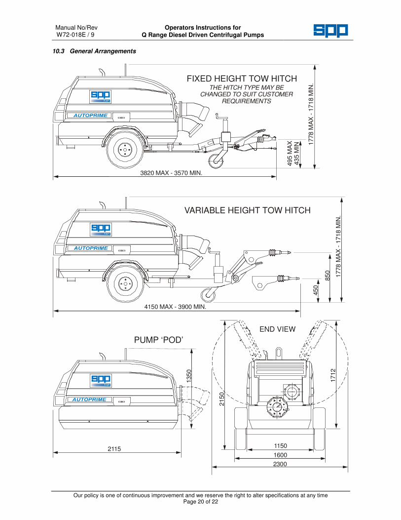
10.3 General Arrangements
3820 MAX - 3570 MIN.
4150 MAX - 3900 MIN.1778 M
AX
- 1
718 M
IN.
49
5 M
AX
43
5 M
IN
1778
MA
X -
1718 M
IN.
21151150
1600
2300
1350
2150
1712
450
85
0
FIXED HEIGHT TOW HITCH
VARIABLE HEIGHT TOW HITCH
PUMP ‘POD’
THE HITCH TYPE MAY BE CHANGED TO SUIT CUSTOMER
REQUIREMENTS
END VIEW

Operators Instructions for Q Range Diesel Driven Centrifugal Pumps
Manual No/Rev W72-018E / 9
Our policy is one of continuous improvement and we reserve the right to alter specifications at any time Page 21 of 22