december, 2000 page tc4-1 - manual on uniform traffic control devices
TRANSCRIPT


December, 2000 Page TC4-1
PART 4. HIGHWAY TRAFFIC SIGNALS
TABLE OF CONTENTS
Page
CHAPTER 4A. GENERAL . . . . . . . . . . . . . . . . . . . . . . . . . . . . . . . . . . . . . .Dec., 2000
Section 4A.01 Types....................................................................................................4A-1Section 4A.02 Definitions Relating to Highway Traffic Signals................................4A-1
CHAPTER 4B. TRAFFIC CONTROL SIGNALS - GENERAL . . . . . . . . .Dec., 2000
Section 4B.01 General.................................................................................................4B-1Section 4B.02 Basis of Installation or Removal of Traffic Control Signals...............4B-1Section 4B.03 Advantages and Disadvantages of Traffic Control Signals.................4B-2Section 4B.04 Alternatives to Traffic Control Signals ...............................................4B-3Section 4B.05 Adequate Roadway Capacity ..............................................................4B-4
CHAPTER 4C. TRAFFIC CONTROL SIGNAL NEEDS STUDIES . . . . .Dec., 2000
Section 4C.01 Studies and Factors for Justifying Traffic Control Signals .................4C-1Section 4C.02 Warrant 1, Eight-Hour Vehicular Volume ...........................................4C-3Section 4C.03 Warrant 2, Four-Hour Vehicular Volume.............................................4C-6Section 4C.04 Warrant 3, Peak Hour ..........................................................................4C-6Section 4C.05 Warrant 4, Pedestrian Volume .............................................................4C-8Section 4C.06 Warrant 5, School Crossing ...............................................................4C-11Section 4C.07 Warrant 6, Coordinated Signal System .............................................4C-12Section 4C.08 Warrant 7, Crash Experience.............................................................4C-12Section 4C.09 Warrant 8, Roadway Network ...........................................................4C-13
CHAPTER 4D. TRAFFIC CONTROL SIGNAL FEATURES . . . . . . . . . .Dec., 2000
Section 4D.01 General ................................................................................................4D-1Section 4D.02 Responsibility For Operation and Maintenance..................................4D-2Section 4D.03 Provisions For Pedestrians ..................................................................4D-3Section 4D.04 Meaning of Vehicular Signal Indications............................................4D-3Section 4D.05 Application of Steady Signal Indications............................................4D-6Section 4D.06 Application of Steady Signal Indications For Left Turns ...................4D-8Section 4D.07 Application of Steady Signal Indications For Right Turns...............4D-11Section 4D.08 Prohibited Steady Signal Indications ................................................4D-14Section 4D.09 Unexpected Conflicts During Green or Yellow Intervals .................4D-14Section 4D.10 Yellow Change and Red Clearance Intervals....................................4D-15Section 4D.11 Application of Flashing Signal Indications.......................................4D-16Section 4D.12 Flashing Operation of Traffic Control Signals..................................4D-17Section 4D.13 Preemption and Priority Control of Traffic Control Signals.............4D-19Section 4D.14 Coordination of Traffic Control Signals ...........................................4D-21Section 4D.15 Size, Number, and Location of Signal Faces by Approach ..............4D-22

Section 4D.16 Number and Arrangement of Signal Sections in Vehicular Traffic Control Signal Faces .........................................................................4D-28
Section 4D.17 Visibility, Shielding, and Positioning of Signal Faces......................4D-30Section 4D.18 Design, Illumination, and Color of Signal Sections .........................4D-33Section 4D.19 Lateral Placement of Signal Supports and Cabinets .........................4D-34Section 4D.20 Temporary Traffic Control Signals ...................................................4D-35Section 4D.21 Traffic Signal Signs, Auxiliary..........................................................4D-36
CHAPTER 4E. PEDESTRIAN CONTROL FEATURES . . . . . . . . . . . . . .Dec., 2000
Section 4E.01 Pedestrian Signal Heads ......................................................................4E-1Section 4E.02 Meaning of Pedestrian Signal Indications...........................................4E-1Section 4E.03 Application of Pedestrian Signal Heads ..............................................4E-2Section 4E.04 Size, Design, and Illumination of Pedestrian Signal Indications ........4E-2Section 4E.05 Location and Height of Pedestrian Signal Heads................................4E-3Section 4E.06 Accessible Pedestrian Signals..............................................................4E-5Section 4E.07 Pedestrian Detectors ............................................................................4E-8Section 4E.08 Accessible Pedestrian Signal Detectors.............................................4E-10Section 4E.09 Pedestrian Intervals and Signal Phases..............................................4E-12
CHAPTER 4F. TRAFFIC CONTROL SIGNALS FOR EMERGENCYVEHICLE ACCESS . . . . . . . . . . . . . . . . . . . . . . . . . . . . . . .Dec., 2000
Section 4F.01 Applications of Emergency-Vehicle Traffic Control Signals ..............4F-1Section 4F.02 Design of Emergency-Vehicle Traffic Control Signals .......................4F-1Section 4F.03 Operation of Emergency-Vehicle Traffic Control Signals...................4F-2
CHAPTER 4G. TRAFFIC CONTROL SIGNALS FOR ONE-LANE, TWO-WAY FACILITIES . . . . . . . . . . . . . . . . . . . . . . . . . .Dec., 2000
Section 4G.01 Application of Traffic Control Signals for One-Lane,Two-Way Facilities..............................................................................4G-1
Section 4G.02 Design of Traffic Control Signals for One-Lane,Two-Way Facilities..............................................................................4G-1
Section 4G.03 Operation of Traffic Control Signals for One-Lane, Two-Way Facilities..............................................................................4G-2
CHAPTER 4H. TRAFFIC CONTROL SIGNALS FOR FREEWAY ENTRANCERAMPS . . . . . . . . . . . . . . . . . . . . . . . . . . . . . . . . . . . . . . . .Dec., 2000
Section 4H.01 Application of Freeway Entrance Ramp Control Signals...................4H-1Section 4H.02 Design of Freeway Entrance Ramp Control Signals ..........................4H-2
CHAPTER 4I. TRAFFIC CONTROL FOR MOVABLE BRIDGES . . . . .Dec., 2000
Section 4I.01 Application of Traffic Control for Movable Bridges ...........................4I-1Section 4I.02 Design and Location of Movable Bridge Signals and Gates ...............4I-2Section 4I.03 Operation of Movable Bridge Signals and Gates.................................4I-4
December, 2000 Page TC4-2

CHAPTER 4J. LANE-USE CONTROL SIGNALS . . . . . . . . . . . . . . . . . . .Dec., 2000
Section 4J.01 Application of Lane-Use Control Signals ............................................4J-1Section 4J.02 Meaning of Lane-Use Control Signal Indications................................4J-2Section 4J.03 Design of Lane-Use Control Signals....................................................4J-3Section 4J.04 Operation of Lane-Use Control Signals ...............................................4J-5
CHAPTER 4K. FLASHING BEACONS . . . . . . . . . . . . . . . . . . . . . . . . . . . .Dec., 2000
Section 4K.01 General Design and Operation of Flashing Beacons ..........................4K-1Section 4K.02 Intersection Control Beacon................................................................4K-1Section 4K.03 Warning Beacon ..................................................................................4K-2Section 4K.04 Speed Limit Sign Beacon....................................................................4K-3Section 4K.05 Stop Beacon.........................................................................................4K-4
CHAPTER 4L. IN-ROADWAY LIGHTS . . . . . . . . . . . . . . . . . . . . . . . . . . .Dec., 2000
Section 4L.01 Application of In-Roadway Lights ......................................................4L-1Section 4L.02 In-Roadway Warning Lights at Crosswalks ........................................4L-1
FIGURES
CHAPTER 4C. TRAFFIC CONTROL SIGNAL NEEDS STUDIES
Figure 4C-1 Warrant 2 - Four-Hour Vehicular Volume ...........................................4C-7Figure 4C-2 Warrant 2 - Four-Hour Vehicular Volume (70% Factor).....................4C-7Figure 4C-3 Warrant 3 - Peak Hour.........................................................................4C-9Figure 4C-4 Warrant 3 - Peak Hour (70% Factor) ..................................................4C-9
CHAPTER 4D. TRAFFIC CONTROL SIGNAL FEATURES
Figure 4D-1 Maximum Mounting Height of Signal Faces Located Between 12 m (40 ft) and 16 m (53 ft) from Stop Line ..................................4D-25
Figure 4D-2 Horizontal Location of Signal Faces.................................................4D-26Figure 4D-3 Typical Arrangements of Signal Lenses in Signal Faces..................4D-31
CHAPTER 4E. PEDESTRIAN CONTROL FEATURES
Figure 4E-1 Typical Pedestrian Signal Indications..................................................4E-4Figure 4E-2 Recommended Pushbutton Locations for Accessible Pedestrian
Signals................................................................................................4E-11
CHAPTER 4J. LANE-USE CONTROL SIGNALS
Figure 4J-1 Left-Turn Lane-Use Control Signals ....................................................4J-3
December, 2000 Page TC4-3

TABLES
CHAPTER 4C. TRAFFIC CONTROL SIGNAL NEEDS STUDIES
Table 4C-1 Warrant 1, Eight-Hour Vehicular Volume ...........................................4C-5
CHAPTER 4D. TRAFFIC CONTROL SIGNAL FEATURES
Table 4D-1 Minimum Sight Distance ..................................................................4D-23
December, 2000 Page TC4-4
CHAPTER 4A. GENERAL
Section 4A.01 Types
Support:
The following types and uses of highway traffic signals are discussed in Part 4: trafficcontrol signals; pedestrian signals; emergency-vehicle traffic control signals; traffic controlsignals for one-lane, two-way facilities; traffic control signals for freeway entrance ramps; trafficcontrol signals for movable bridges; lane-use control signals; flashing beacons; and in-roadwaylights.
Section 4A.02 Definitions Relating to Highway Traf fic Signals
Standard:
The following technical terms, when used in Part 4, shall be defined as follows:
1. Accessible Pedestrian Signal - a device that communicates information aboutpedestrian timing in non-visual format such as audible tones, verbalmessages, and/or vibrating surfaces.
2. Active Grade Crossing Warning System - the flashing-light signals, with orwithout warning gates, together with the necessary control equipment usedto inform road users of the approach or presence of trains at highway-railgrade crossings.
3. Actuated Operation - a type of traffic control signal operation in which someor all signal phases are operated on the basis of actuation.
4. Actuation - initiation of a change in or extension of a traffic signal phasethrough the operation of any type of detector.
5. Approach - all lanes of traffic moving towards an intersection or a mid-block location from one direction, including any adjacent parking lane(s).
6. Average Day - a day representing traffic volumes normally and repeatedlyfound at a location, typically a weekday when volumes are influenced byemployment or a weekend when volumes are influenced by entertainment orrecreation.
7. Backplate - a thin strip of material that extends outward from and parallelto a signal face on all sides of a signal housing to provide a background forimproved visibility of the signal indications.
December, 2000 Page 4A-1
Sect. 4A.01 to 4A.02

8. Beacon - a highway traffic signal with one or more signal sections thatoperates in a flashing mode.
9. Conflict Monitor - a device used to detect and respond to improper orconflicting signal indications and improper operating voltages in a trafficcontroller assembly.
10. Controller Assembly - a complete electrical device mounted in a cabinet forcontrolling the operation of a highway traffic signal.
11. Controller Unit - that part of a controller assembly that is devoted to theselection and timing of the display of signal indications.
12. Crosswalk - (a) that part of a roadway at an intersection included within theconnections of the lateral lines of the sidewalks on opposite sides of thehighway measured from the curbs or in the absence of curbs, from the edgesof the traversable roadway, and in the absence of a sidewalk on one side ofthe roadway, the part of a roadway included within the extension of thelateral lines of the sidewalk at right angles to the centerline; (b) any portionof a roadway at an intersection or elsewhere distinctly indicated forpedestrian crossing by lines or other markings on the surface.
13. Cycle Length - the time required for one complete sequence of signalindications.
14. Dark Mode - the lack of all signal indications at a signalized location. (Thedark mode is most commonly associated with power failures, ramp meters,beacons, and some movable bridge signals.)
15. Detector - a sensing device used for determining the presence or passage ofvehicles or pedestrians.
16. Emergency Vehicle Traffic Control Signal - a special traffic control signalthat assigns the right-of-way to an authorized emergency vehicle.
17. Flasher - a device used to turn highway traffic signal indications on and offat a repetitive rate of approximately once per second.
18. Flashing (Flashing Mode) - a mode of operation in which a traffic signalindication is turned on and off repetitively.
19. Full-actuated Operation - a type of traffic control signal operation in whichall signal phases function on the basis of actuation.
December, 2000 Page 4A-2
Sect. 4A.02

20. Highway Traffic Signal - a power-operated traffic control device by whichtraffic is warned or directed to take some specific action. These devices donot include power-operated signs, illuminated pavement markers, barricadewarning lights, or steady-burning electric lamps.
21. In-Roadway Lights - a special type of highway traffic signal installed in theroadway surface to warn road users that they are approaching a conditionon or adjacent to the roadway that might not be readily apparent and mightrequire the road users to slow down and/or come to a stop.
22. Intersection - (a) the area embraced within the prolongation or connection ofthe lateral curb lines, or if none, the lateral boundary lines of the roadwaysof two highways that join one another at, or approximately at, right angles,or the area within which vehicles traveling on different highways that join atany other angle may come into conflict; (b) the junction of an alley ordriveway with a roadway or highway shall not constitute an intersection.
23. Intersection Control Beacon - a beacon used only at an intersection tocontrol two or more directions of travel.
24. Interval - the part of a signal cycle during which signal indications do notchange.
25. Interval Sequence - the order of appearance of signal indications duringsuccessive intervals of a signal cycle.
26. Lane-use Control Signal - a signal face displaying signal indications topermit or prohibit the use of specific lanes of a roadway or to indicate theimpending prohibition of such use.
27. Lens - see Signal Lens.
28. Louver - a device that can be mounted inside a signal visor to restrictvisibility of a signal indication from the side or to limit the visibility of thesignal indication to a certain lane or lanes.
29. Major Street - the street normally carrying the higher volume of vehiculartraffic.
30. Malfunction Management Unit - same as Conflict Monitor.
31. Minor Street - the street normally carrying the lower volume of vehiculartraffic.
December, 2000 Page 4A-3
Sect. 4A.02

32. Movable Bridge Resistance Gate - a type of traffic gate, which is locateddownstream of the movable bridge warning gate, that provides a physicaldeterrent to vehicle and/or pedestrian traffic when placed in the appropriateposition.
33. Movable Bridge Warning Gate - a type of traffic gate designed to warn, butnot primarily to block, vehicle and/or pedestrian traffic when placed in theappropriate position.
34. Pedestrian Change Interval - an interval during which the flashingUPRAISED HAND (symbolizing DONT WALK) signal indication isdisplayed. When a verbal message is provided at an accessible pedestriansignal, the verbal message is "wait."
35. Pedestrian Clearance Time - the time provided for a pedestrian crossing in acrosswalk, after leaving the curb or shoulder, to travel to the center of thefarthest traveled lane or to a median.
36. Pedestrian Signal Head - a signal head, which contains the symbolsWALKING PERSON (symbolizing WALK) and UPRAISED HAND(symbolizing DONT WALK), that is installed to direct pedestrian traffic at atraffic control signal.
37. Permissive Mode - a mode of traffic control signal operation in which, whena CIRCULAR GREEN signal indication is displayed, left or right turns maybe made after yielding to pedestrians and/or oncoming traffic.
38. Platoon - a group of vehicles or pedestrians traveling together as a group,either voluntarily or involuntarily, because of traffic signal controls,geometrics, or other factors.
39. Preemption Control - the transfer of normal operation of a traffic controlsignal to a special control mode of operation.
40. Pretimed Operation - a type of traffic control signal operation in which noneof the signal phases function on the basis of actuation.
41. Priority Control - a means by which the assignment of right-of-way isobtained or modified.
42. Protected Mode - a mode of traffic control signal operation in which left orright turns may be made when a left or right GREEN ARROW signalindication is displayed.
December, 2000 Page 4A-4
Sect. 4A.02

43. Pushbutton - a button to activate pedestrian timing.
44. Pushbutton Locator Tone - a repeating sound that informs approachingpedestrians that they are required to push a button to actuate pedestriantiming and that enables pedestrians who have visual disabilities to locate thepushbutton.
45. Ramp Control Signal - a highway traffic signal installed to control the flowof traffic onto a freeway at an entrance ramp or at a freeway-to-freewayramp connection.
46. Ramp Meter - see Ramp Control Signal.
47. Red Clearance Interval - an optional interval that follows a yellow changeinterval and precedes the next conflicting green interval.
48. Right-of-Way (Assignment) - the permitting of vehicles and/or pedestrians toproceed in a lawful manner in preference to other vehicles or pedestrians bythe display of signal indications.
49. Roadway Network - a geographical arrangement of intersecting roadways.
50. Semi-Actuated Operation - a type of traffic control signal operation in whichat least one, but not all, signal phases function on the basis of actuation.
51. Signal Coordination - the establishment of timed relationships betweenadjacent traffic control signals.
52. Signal Face - the front part of a signal head.
53. Signal Head - an assembly of one or more signal faces together with theassociated signal housings.
54. Signal Housing - that part of a signal section that protects the light sourceand other required components.
55. Signal Indication - the illumination of a signal lens or equivalent device.
56. Signal Lens - that part of the signal section that redirects the light comingdirectly from the light source and its reflector, if any.
57. Signal Phase - the right-of-way, yellow change, and red clearance intervals ina cycle that are assigned to an independent traffic movement or combinationof movements.
58. Signal Section - the assembly of a signal housing, signal lens, and light
December, 2000 Page 4A-5
Sect. 4A.02

source with necessary components to be used for providing one signalindication.
59. Signal System - two or more traffic control signals operating in signalcoordination.
60. Signal Timing - the amount of time allocated for the display of a signalindication.
61. Signal Visor - that part of a signal section that directs the signal indicationspecifically to approaching traffic and reduces the effect of direct externallight entering the signal lens.
62. Signal Warrant - a threshold condition that, if found to be satisfied as partof an engineering study, shall result in analysis of other traffic conditions orfactors to determine whether a traffic control signal or other improvement isjustified.
63. Speed Limit Sign Beacon - a beacon used to supplement a SPEED LIMITsign.
64. Steady (Steady Mode) - the continuous illumination of a signal indication forthe duration of an interval, signal phase, or consecutive signal phases.
65. Stop Beacon - a beacon used to supplement a STOP sign, a DO NOTENTER sign, or a WRONG WAY sign.
66. Traffic Control Signal (Traffic Signal) - any highway traffic signal by whichtraffic is alternately directed to stop and permitted to proceed.
67. Vibrotactile Pedestrian Device - a device that communicates, by touch,information about pedestrian timing using a vibrating surface.
68. Visibility-Limited Signal Face or Signal Section - a type of signal face orsignal section designed to restrict the visibility of a signal indication from theside, to a certain lane or lanes, or to a certain distance from the stop line.
69. Walk Interval - an interval during which the WALKING PERSON(symbolizing WALK) signal indication is displayed. When a verbal messageis provided at an accessible pedestrian signal, the verbal message is "walksign."
70. Warning Beacon - a beacon used only to supplement an appropriatewarning or regulatory sign or marker.
71. Yellow Change Interval - the first interval following the green intervalduring which the yellow signal indication is displayed.
December, 2000 Page 4A-6
Sect. 4A.02

CHAPTER 4B. TRAFFIC CONTROL SIGNALS - GENERAL
Section 4B.01 General
Standard:
A traffic control signal (traffic signal) shall be defined as any highway trafficsignal by which traffic is alternately directed to stop and permitted to proceed.
Traffic shall be defined as pedestrians, bicyclists, ridden or herded animals,vehicles, streetcars, and other conveyances either singularly or together while usingany highway for purposes of travel.
Support:
Words such as pedestrians and bicyclists are used redundantly in selected sections of Part 4to encourage sensitivity to these elements of "traffic."
Standards for traffic control signals are important because traffic control signals need toattract the attention of virtually every road user, including those who are older, those withimpaired vision who meet legal requirements, as well as those who are fatigued or distracted, orwho are not expecting to encounter a signal at a particular location. Standards for traffic controlsignals are also important because signals need to function reliably under a wide range ofconditions including day and night, adverse weather, and visually-complex surroundings.
Section 4B.02 Basis of Installation or Removal of Traf fic Control Signals
Guidance:
The selection and use of traffic control signals should be based on an engineeringstudy of roadway, pedestrian, bicyclist, and other conditions.
Support:
A careful analysis of traffic operations, pedestrian, and bicyclist needs, and other factors at alarge number of signalized and unsignalized intersections, coupled with engineering judgment,has provided a series of signal warrants, described in Chapter 4C, that define the minimumconditions under which installing traffic control signals might be justified.
Guidance:
If changes in traffic patterns eliminate the need for a traffic control signal,consideration should be given to removing it and replacing it with appropriate alternativetraffic control devices, if any are needed.
December, 2000 Page 4B-1
Sect. 4B.01 to 4B.02

Option:
If the engineering study indicates that the traffic control signal is no longer justified, removalmay be accomplished using the following steps:
A. Determine the appropriate traffic control to be used after removal of the signal.
B. Remove any sight-distance restrictions as necessary.
C. Inform the public of the removal study, for example by installing an informational sign(or signs) with the legend TRAFFIC SIGNAL UNDER STUDY FOR REMOVAL at thesignalized location in a position where it is visible to all road users.
D. Flash or cover the signal heads for a minimum of 90 days, and install the appropriatestop control or other traffic control devices.
E. Remove the signal if the engineering data collected during the removal study periodconfirms that the signal is no longer needed. Instead of total removal of the trafficcontrol signal, the poles and cables may remain in place for 1 year after removal of thesignal heads for continued analysis.
Section 4B.03 Advantages and Disadvantages of Traf fic Control Signals
Support:
When properly used, traffic control signals are valuable devices for the control of vehicularand pedestrian traffic. They assign the right-of-way to the various traffic movements andthereby profoundly influence traffic flow.
Traffic control signals that are properly designed, located, operated, and maintained willhave one or more of the following advantages:
A. They provide for the orderly movement of traffic.
B. They increase the traffic-handling capacity of the intersection if proper physical layoutsand control measures are used, and if the signal timing is reviewed and updated on aregular basis (every 2 years) to ensure that it satisfies current traffic demands.
C. They reduce the frequency and severity of certain types of crashes, especially right-anglecollisions.
D. They are coordinated to provide for continuous or nearly continuous movement of trafficat a definite speed along a given route under favorable conditions.
E. They are used to interrupt heavy traffic at intervals to permit other traffic, vehicular orpedestrian, to cross.
December, 2000 Page 4B-2
Sect. 4B.02 to 4B.03

Traffic control signals are often considered a panacea for all traffic problems at intersections.This belief has led to traffic control signals being installed at many locations where they are notneeded, adversely affecting the safety and efficiency of vehicular, bicycle, and pedestrian traffic.
Traffic control signals, even when justified by traffic and roadway conditions, can be ill-designed, ineffectively placed, improperly operated, or poorly maintained. Improper orunjustified traffic control signals can result in one or more of the following disadvantages:
A. Excessive delay.
B. Excessive disobedience of the signal indications.
C. Increased use of less adequate routes as road users attempt to avoid the traffic controlsignals.
D. Significant increases in the frequency of collisions (especially rear-end collisions).
Engineering studies of operating traffic control signals should be made to determine whetherthe type of installation and the timing program meet the current requirements of traffic.
Section 4B.04 Alternatives to Traf fic Control Signals
Guidance:
Since vehicular delay and the frequency of some types of crashes are sometimesgreater under traffic signal control than under STOP sign control, consideration shouldbe given to providing alternatives to traffic control signals even if one or more of thesignal warrants has been satisfied.
Option:
These alternatives may include, but are not limited to, the following:
A. Installing signs along the major street to warn road users approaching the intersection.
B. Relocating the stop line(s) and making other changes to improve the sight distance at theintersection.
C. Installing measures designed to reduce speeds on the approaches.
D. Installing a flashing beacon at the intersection to supplement STOP sign control.
E. Installing flashing beacons on warning signs in advance of a STOP sign controlledintersection on major- and/or minor-street approaches.
F. Adding one or more lanes on a minor-street approach to reduce the number of vehiclesper lane on the approach.
December, 2000 Page 4B-3
Sect. 4B.03 to 4B.04
December, 2000 Page 4B-4
Sect. 4B.04 to 4B.05
G. Revising the geometrics at the intersection to channelize vehicular movements andreduce the time required for a vehicle to complete a movement, which could also assistpedestrians.
H. Installing roadway lighting if a disproportionate number of crashes occur at night.
I. Restricting one or more turning movements, perhaps on a time-of-day basis, if alternateroutes are available.
J. If the warrant is satisfied, installing multi-way STOP sign control.
K. Installing a roundabout.
L. Employing other alternatives, depending on conditions at the intersection.
Section 4B.05 Adequate Roadway Capacity
Support:
The delays inherent in the alternating assignment of right-of-way at intersections controlledby traffic control signals can frequently be reduced by widening the major roadway, the minorroadway, or both roadways. Widening the minor roadway often benefits the operations on themajor roadway, because it reduces the green time that must be assigned to minor-roadway traffic.In urban areas, the effect of widening can be achieved by eliminating parking on intersectionapproaches. It is desirable to have at least two lanes for moving traffic on each approach to asignalized intersection. Additional width on the departure side of the intersection, as well as onthe approach side, will sometimes be needed to clear traffic through the intersection effectively.
Guidance:
Adequate roadway capacity should be provided at a signalized location. Before anintersection is widened, the additional green time pedestrians need to cross the widenedroadways should be considered to ensure that it will not exceed the green time savedthrough improved vehicular flow.

CHAPTER 4C. TRAFFIC CONTROL SIGNAL NEEDS STUDIES
Section 4C.01 Studies and Factors for Justifying Traf fic Control Signals
Standard:
An engineering study of traffic conditions, pedestrian characteristics, andphysical characteristics of the location shall be performed to determine whetherinstallation of a traffic control signal is justified at a particular location.
The investigation of the need for a traffic control signal shall include an analysisof the applicable factors contained in the following traffic signal warrants andother factors related to existing operation and safety at the study location:
Warrant 1, Eight-Hour Vehicular Volume.Warrant 2, Four-Hour Vehicular Volume.Warrant 3, Peak Hour.Warrant 4, Pedestrian Volume.Warrant 5, School Crossing.Warrant 6, Coordinated Signal System.Warrant 7, Crash Experience.Warrant 8, Roadway Network.
The satisfaction of a traffic signal warrant or warrants shall not in itself requirethe installation of a traffic control signal.
Support:
Sections 8D.07 and 10D.05 contain information regarding the use of traffic control signalsinstead of gates and/or flashing light signals at highway-railroad grade crossings and highway-LRT grade crossings, respectively.
Guidance:
A traffic control signal should not be installed unless one or more of the factorsdescribed in this section are met.
A traffic control signal should not be installed unless an engineering study indicatesthat installing a traffic control signal will improve the overall safety and/or operation ofthe intersection.
A traffic control signal should not be installed if it will seriously disrupt progressivetraffic flow.
The study should consider the effects of the right-turn vehicles from the minor-street
December, 2000 Page 4C-1
Sect. 4C.01

approaches. Engineering judgment should be used to determine what, if any, portion ofthe right-turn traffic is subtracted from the minor-street traffic count when evaluating thecount against the above signal warrants.
Engineering judgment should also be used in applying various traffic signal warrantsto cases where approaches consist of one lane plus one left-turn or right-turn lane. Thesite-specific traffic characteristics dictate whether an approach should be considered asone lane or two lanes. For example, for an approach with one lane for through andright-turning traffic plus a left-turn lane, engineering judgment could indicate that itshould be considered a one-lane approach if the traffic using the left-turn lane is minor.In such a case, the total traffic volume approaching the intersection should be appliedagainst the signal warrants as a one-lane approach. The approach should be consideredtwo lanes if approximately half of the traffic on the approach turns left and the left-turnlane is of sufficient length to accommodate all left-turn vehicles.
Similar engineering judgment and rationale should be applied to a street approachwith one lane plus a right-turn lane. In this case, the degree of conflict of minor-streetright-turn traffic with traffic on the major street should be considered. Thus, right-turntraffic should not be included in the minor-street volume if the movement enters themajor street with minimal conflict. The approach should be evaluated as a one-laneapproach with only the traffic volume in the through/left-turn lane considered.
At a location that is under development or construction and where it is not possibleto obtain a traffic count that would represent future traffic conditions, hourly volumesshould be estimated as part of an engineering study for comparison with traffic signalwarrants.
For signal warrant analysis, a location with a wide median should be considered asone intersection.
Option:
Engineering study data may include the following:
A. The number of vehicles entering the intersection in each hour from each approach during12 hours of an average day. It is desirable that the hours selected contain the greatestpercentage of the 24-hour traffic volume.
B. Vehicular volumes for each traffic movement from each approach, classified by vehicletype (heavy trucks, passenger cars and light trucks, public-transit vehicles, and, in somelocations, bicycles), during each 15-minute period of the 2 hours in the morning and 2hours in the afternoon during which total traffic entering the intersection is greatest.
C. Pedestrian volume counts on each crosswalk during the same periods as the vehicularcounts in Paragraph B above and during hours of highest pedestrian volume. Whereyoung, elderly, and/or persons with physical or visual disabilities need special
December, 2000 Page 4C-2
Sect. 4C.01
consideration, the pedestrians and their crossing times may be classified by generalobservation.
D. Information about nearby facilities and activity centers that serve the young, elderly,and/or persons with disabilities, including requests from persons with disabilities foraccessible crossing improvements at the location under study. These persons may not beadequately reflected in the pedestrian volume count if the absence of a signal restrainstheir mobility.
E. The posted or statutory speed limit or the 85th-percentile speed on the uncontrolledapproaches to the location.
F. A condition diagram showing details of the physical layout, including such features asintersection geometrics, channelization, grades, sight-distance restrictions, transit stopsand routes, parking conditions, pavement markings, roadway lighting, driveways, nearbyrailroad crossings, distance to nearest traffic control signals, utility poles and fixtures,and adjacent land use.
G. A collision diagram showing crash experience by type, location, direction of movement,severity, weather, time of day, date, and day of week for at least 1 year.
The following data, which are desirable for a more precise understanding of the operation ofthe intersection, may be obtained during the periods specified in Paragraph B above:
A. Vehicle-hours of stopped time delay determined separately for each approach to beconsistent with the Peak Hour Warrant.
B. The number and distribution of acceptable gaps in vehicular traffic on the major streetfor entrance from the minor street.
C. The posted or statutory speed limit or the 85th-percentile speed on controlled approachesat a point near to the intersection but unaffected by the control.
D. Pedestrian delay time for at least two 30-minute peak pedestrian delay periods of anaverage weekday or like periods of a Saturday or Sunday.
E. Queue length on stop-controlled approaches.
Section 4C.02 Warrant 1, Eight-Hour Vehicular Volume
Support:
The Minimum Vehicular Volume, Condition A, is intended for application where a largevolume of intersecting traffic is the principal reason to consider installing a traffic control signal.
The Interruption of Continuous Traffic, Condition B, is intended for application where thetraffic volume on a major street is so heavy that traffic on a minor intersecting street suffersexcessive delay or conflict in entering or crossing the major street.
December, 2000 Page 4C-3
Sect. 4C.01 to 4C.02

Standard:
The need for a traffic control signal shall be considered if an engineering studyfinds that one of the following conditions exist for each of any 8 hours of an averageday:
A. The vehicles per hour given in both of the 100% columns of Condition A inTable 4C-1 exist on the major street and on the higher volume minor-streetapproaches, respectively, to the intersection, or
B. The vehicles per hour given in both of the 100% columns of Condition B inTable 4C-1 exist on the major street and on the higher volume minor-streetapproaches, respectively, to the intersection.
In applying each condition the major street and minor-street volumes shall be forthe same 8 hours. On the minor street, the higher volume shall not be required tobe on the same approach during each of these 8 hours.
Option:
If the posted or statutory speed limit or the 85th-percentile speed on the major street exceeds70 km/h (40 mph), or if the intersection lies within the built-up area of an isolated communityhaving a population of less than 10,000, the traffic volumes in the 70% columns in Table 4C-1may be used in place of the 100% columns.
Standard:
The need for a traffic control signal shall be considered if an engineering studyfinds that both of the following conditions exist for each of any 8 hours of anaverage day:
A. The vehicles per hour given in both of the 80% columns of Condition A inTable 4C-1 exist on the major street and on the higher volume minor-streetapproaches, respectively, to the intersection, and
B. The vehicles per hour given in both of the 80% columns of Condition B inTable 4C-1 exist on the major street and on the higher volume minor-streetapproaches, respectively, to the intersection.
These major street and minor-street volumes shall be for the same 8 hours for eachcondition; however, the 8 hours satisfied in Condition A shall not be required to bethe same 8 hours satisfied in Condition B. On the minor street the higher volumeshall not be required to be on the same approach during each of the 8 hours.
December, 2000 Page 4C-4
Sect. 4C.02

December, 2000 Page 4C-5
Sect. 4C.02
Number of lanes for moving traffic on each approach
Major Street Minor Street
1................. 1.................2 or more... 1.................2 or more... 2 or more ...1................. 2 or more ....
Vehicles per hour on major street(total of both approaches)
100%a 80%b 70%c
500 400 350600 480 420600 480 420500 400 350
Vehicles per hour on higher-volume
minor-street approach(one direction only)
100%a 80%b 70%c
150 120 105150 120 105200 160 140200 160 140
Table 4C-1. Warrant 1, Eight-Hour Vehicular Volume
Condition A - Minimum Vehicular Volume
Number of lanes for moving traffic on each approach
Major Street Minor Street
1................. 1.................2 or more... 1.................2 or more... 2 or more ...1................. 2 or more ....
Condition B - Interruption of Continuous Traffic
Vehicles per hour on major street(total of both approaches)
100%a 80%b 70%c
750 600 525900 720 630900 720 630750 600 525
Vehicles per hour onhigher-volume
minor-street approach(one direction only)
100%a 80%b 70%c
75 60 5375 60 53100 80 70100 80 70
aBasic minimum hourly volume.
bUsed for combination of Conditions A and B after adequate trial of other remedial measures.
cMay be used when the major street speed exceeds 70 km/h (40 mph) or in an isolated community with a population of less than 10,000.

Guidance:
The combination of Conditions A and B should be applied only after an adequatetrial of other alternatives that could cause less delay and inconvenience to traffic hasfailed to solve the traffic problems.
Section 4C.03 Warrant 2, Four-Hour Vehicular Volume
Support:
The Four-Hour Vehicular Volume signal warrant conditions are intended to be applied wherethe volume of intersecting traffic is the principal reason to consider installing a traffic controlsignal.
Standard:
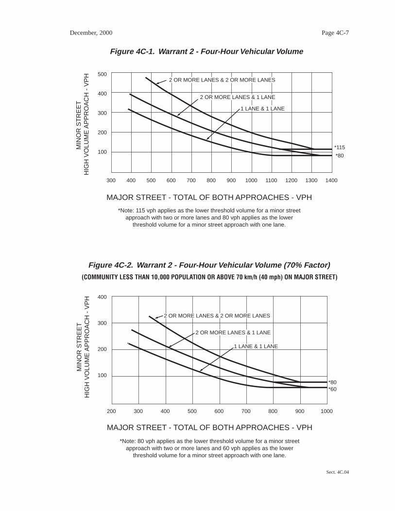
The need for a traffic control signal shall be considered if an engineering studyfinds that for each of any 4 hours of an average day, the plotted points representingthe vehicles per hour on the major street (total of both approaches) and thecorresponding vehicles per hour on the higher volume minor-street approach (onedirection only) all fall above the applicable curve in Figure 4C-1 for the existingcombination of approach lanes. On the minor street, the higher volume shall not berequired to be on the same approach during each of these 4 hours.
Option:
If the posted or statutory speed limit or the 85th-percentile speed on the major street exceeds70 km/h (40 mph), or if the intersection lies within the built-up area of an isolated communityhaving a population of less than 10,000, Figure 4C-2 may be used in place of Figure 4C-1.
Section 4C.04 Warrant 3, Peak Hour
Support:
The Peak Hour signal warrant is intended for use at a location where traffic conditions aresuch that for a minimum of 1 hour of an average day, the minor-street traffic suffers undue delaywhen entering or crossing the major street.
Standard:
This signal warrant shall be applied only in unusual cases. Such cases include,but are not limited to, office complexes, manufacturing plants, industrialcomplexes, or high-occupancy vehicle facilities that attract or discharge largenumbers of vehicles over a short time.
December, 2000 Page 4C-6
Sect. 4C.02 to 4C.04
December, 2000 Page 4C-7
Sect. 4C.04
Figure 4C-1. Warrant 2 - Four-Hour Vehicular Volume
100
300 400 500 600 700 800 900 1000 1100 1200 1300 1400
200
300
400
500
*115
*80
*Note: 115 vph applies as the lower threshold volume for a minor streetapproach with two or more lanes and 80 vph applies as the lower
threshold volume for a minor street approach with one lane.
MAJOR STREET - TOTAL OF BOTH APPROACHES - VPH
MIN
OR
ST
RE
ET
HIG
H V
OLU
ME
AP
PR
OA
CH
- V
PH
2 OR MORE LANES & 2 OR MORE LANES
2 OR MORE LANES & 1 LANE
1 LANE & 1 LANE
Figure 4C-2. Warrant 2 - Four-Hour Vehicular Volume (70% Factor)
100
200 300 400 500 600 700 800 900 1000
200
300
400
*80*60
*Note: 80 vph applies as the lower threshold volume for a minor streetapproach with two or more lanes and 60 vph applies as the lower
threshold volume for a minor street approach with one lane.
MAJOR STREET - TOTAL OF BOTH APPROACHES - VPH
MIN
OR
ST
RE
ET
HIG
H V
OLU
ME
AP
PR
OA
CH
- V
PH
(COMMUNITY LESS THAN 10,000 POPULATION OR ABOVE 70 km/h (40 mph) ON MAJOR STREET)
2 OR MORE LANES & 2 OR MORE LANES
2 OR MORE LANES & 1 LANE
1 LANE & 1 LANE

The need for a traffic control signal shall be considered if an engineering studyfinds that the criteria in either of the following two categories are met:
A. If all three of the following conditions exist for the same 1 hour (any fourconsecutive 15-minute periods) of an average day:
1. The total stopped time delay experienced by the traffic on one minor-street approach (one direction only) controlled by a STOP sign equals orexceeds: 4 vehicle-hours for a one-lane approach; or 5 vehicle-hours for atwo-lane approach, and
2. The volume on the same minor-street approach (one direction only)equals or exceeds 100 vehicles per hour for one moving lane of traffic or150 vehicles per hour for two moving lanes, and
3. The total entering volume serviced during the hour equals or exceeds 650vehicles per hour for intersections with three approaches or 800 vehiclesper hour for intersections with four or more approaches.
B. The plotted point representing the vehicles per hour on the major street(total of both approaches) and the corresponding vehicles per hour on thehigher-volume minor-street approach (one direction only) for 1 hour (anyfour consecutive 15-minute periods) of an average day falls above theapplicable curve in Figure 4C-3 for the existing combination of approachlanes.
Option:
If the posted or statutory speed limit or the 85th-percentile speed on the major street exceeds70 km/h (40 mph), or if the intersection lies within the built-up area of an isolated communityhaving a population of less than 10,000, Figure 4C-4 may be used in place of Figure 4C-3 tosatisfy the criteria in the second category of the Standard.
4C.05 Warrant 4, Pedestrian Volume
Support:
The Pedestrian Volume signal warrant is intended for application where the traffic volume ona major street is so heavy that pedestrians experience excessive delay in crossing the majorstreet.
December, 2000 Page 4C-8
Sect. 4C.04 to 4C.05

December, 2000 Page 4C-9
Sect. 4C.05
100
400 500 600 700 800 900 1000 1100 1200 1300 1400 1500 1600 1700 1800
200
300
400
500
600
*150
*100
*Note: 150 vph applies as the lower threshold volume for a minor streetapproach with two or more lanes and 100 vph applies as the lower
threshold volume for a minor street approach with one lane.
MAJOR STREET - TOTAL OF BOTH APPROACHES - VPH
MIN
OR
ST
RE
ET
HIG
H V
OLU
ME
AP
PR
OA
CH
- V
PH
2 OR MORE LANES & 2 OR MORE LANES
2 OR MORE LANES & 1 LANE
1 LANE & 1 LANE
Figure 4C-3. Warrant 3 - Peak Hour
Figure 4C-4. Warrant 3 - Peak Hour (70% Factor)
100
300 400 500 600 700 800 900 1000 1100 1200 1300
200
300
400
*100*75
*Note: 100 vph applies as the lower threshold volume for a minor streetapproach with two or more lanes and 75 vph applies as the lower
threshold volume for a minor street approach with one lane.
MAJOR STREET - TOTAL OF BOTH APPROACHES - VPH
MIN
OR
ST
RE
ET
HIG
H V
OLU
ME
AP
PR
OA
CH
- V
PH
(COMMUNITY LESS THAN 10,000 POPULATION OR ABOVE 70 km/h (40 mph) ON MAJOR STREET)
2 OR MORE LANES & 2 OR MORE LANES
1 LANE & 1 LANE
2 OR MORE LANES & 1 LANE

Standard:
The need for a traffic control signal at an intersection or mid-block crossingshall be considered if an engineering study finds that both of the following criteriaare met:
A. The pedestrian volume crossing the major street at an intersection or mid-block location during an average day is 100 or more for each of any 4 hoursor 190 or more during any 1 hour, and
B. There are fewer than 60 gaps per hour in the traffic stream of adequatelength to allow pedestrians to cross during the same period when thepedestrian volume criterion is satisfied. Where there is a divided streethaving a median of sufficient width for pedestrians to wait, the requirementapplies separately to each direction of vehicular traffic.
The Pedestrian Volume signal warrant shall not be applied at locations wherethe distance to the nearest traffic control signal along the major street is less than90 m (300 ft), unless the proposed traffic control signal will not restrict theprogressive movement of traffic.
If a traffic control signal is justified by both this signal warrant and a trafficengineering study, the traffic control signal shall be equipped with pedestrian signalheads conforming to requirements set forth in Chapter 4E.
Guidance:
If a traffic control signal is justified by both this signal warrant and a trafficengineering study:
A. If installed within a signal system, the traffic control signal should becoordinated.
B. At an intersection, the traffic control signal should be traffic-actuated and shouldinclude pedestrian detectors. As a minimum, it should have semi-actuatedoperation, but full-actuated operation with detectors on all approaches might alsobe appropriate.
C. At non-intersection crossings, the traffic control signal should be pedestrian-actuated, parking and other sight obstructions should be prohibited for at least 30m (100 ft) in advance of and at least 6.1 m (20 ft) beyond the crosswalk, and theinstallation should include suitable standard signs and pavement markings.
December, 2000 Page 4C-10
Sect. 4C.05

Option:
The criterion for the pedestrian volume crossing the major roadway may be reduced as muchas 50 percent if the average crossing speed of pedestrians is less than 1.2 m/sec (4 ft/sec).
A traffic control signal may not be needed at the study location if adjacent coordinated trafficcontrol signals consistently provide gaps of adequate length for pedestrians to cross the street,even if the rate of gap occurrence is less than one per minute.
Section 4C.06 Warrant 5, School Crossing
Support:
The School Crossing signal warrant is intended for application where the fact that schoolchildren cross the major street is the principal reason to consider installing a traffic controlsignal.
Standard:
The need for a traffic control signal shall be considered when an engineeringstudy of the frequency and adequacy of gaps in the vehicular traffic stream asrelated to the number and size of groups of school children at an established schoolcrossing across the major street shows that the number of adequate gaps in thetraffic stream during the period when the children are using the crossing is lessthan the number of minutes in the same period (see Section 7A.03) and there are aminimum of 20 students during the highest crossing hour.
Before a decision is made to install a traffic control signal, consideration shallbe given to the implementation of other remedial measures, such as warning signsand flashers, school speed zones, school crossing guards, or a grade-separatedcrossing.
The School Crossing signal warrant shall not be applied at locations where thedistance to the nearest traffic control signal along the major street is less than 90 m(300 ft), unless the proposed traffic control signal will not restrict the progressivemovement of traffic.
Guidance:
If a traffic control signal is justified by both this signal warrant and an engineeringstudy:
A. If installed within a signal system, the traffic control signal should becoordinated.
December, 2000 Page 4C-11
Sect. 4C.05 to 4C.06

B. At an intersection, the traffic control signal should be traffic-actuated and shouldinclude pedestrian detectors. As a minimum, it should have semi-actuatedoperation, but full-actuated operation with detectors on all approaches might alsobe appropriate.
C. At non-intersection crossings, the traffic control signal should be pedestrian-actuated, parking and other sight obstructions should be prohibited for at least 30m (100 ft) in advance of and at least 6.1 m (20 ft) beyond the crosswalk, and theinstallation should include suitable standard signs and pavement markings.
Section 4C.07 Warrant 6, Coordinated Signal System
Support:
Progressive movement in a coordinated signal system sometimes necessitates installingtraffic control signals at intersections where they would not otherwise be needed in order tomaintain proper platooning of vehicles.
Standard:
The need for a traffic control signal shall be considered if an engineering studyfinds that one of the following criteria is met:
A. On a one-way street or a street that has traffic predominantly in onedirection, the adjacent traffic control signals are so far apart that they donot provide the necessary degree of vehicular platooning.
B. On a two-way street, adjacent traffic control signals do not provide thenecessary degree of platooning and the proposed and adjacent traffic controlsignals will collectively provide a progressive operation.
Guidance:
The Coordinated Signal System signal warrant should not be applied where theresultant spacing of traffic control signals would be less than 300 m (1,000 ft).
Section 4C.08 Warrant 7, Crash Experience
Support:
The Crash Experience signal warrant conditions are intended for application where theseverity and frequency of crashes are the principal reasons to consider installing a traffic controlsignal.
December, 2000 Page 4C-12
Sect. 4C.07 to 4C.08

Standard:
The need for a traffic control signal shall be considered if an engineering studyfinds that all of the following criteria are met:
A. Adequate trial of alternatives with satisfactory observance and enforcementhas failed to reduce the crash frequency, and
B. Five or more reported crashes, of types susceptible to correction by a trafficcontrol signal, have occurred within a 12-month period, each crash involvingpersonal injury or property damage apparently exceeding the applicablerequirements for a reportable crash, and
C. For each of any 8 hours of an average day, the vehicles per hour (vph) givenin both of the 80% columns of Condition A in Table 4C-1 (see Section4C.02), or the vph in both of the 80% columns of Condition B in Table 4C-1exists on the major street and on the higher-volume minor-street approach,respectively, to the intersection, or the volume of pedestrian traffic is not lessthan 80 percent of the requirements specified in the Pedestrian Volumewarrant. These major-street and minor-street volumes shall be for the same8 hours. On the minor street, the higher volume shall not be required to beon the same approach during each of the 8 hours.
Section 4C.09 Warrant 8, Roadway Network
Support:
Installing a traffic control signal at some intersections might be justified to encourageconcentration and organization of traffic flow on a roadway network.
Standard:
The need for a traffic control signal shall be considered if an engineering studyfinds that the common intersection of two or more major routes meets one or bothof the following criteria:
A. The intersection has a total existing, or immediately projected, enteringvolume of at least 1,000 vehicles per hour during the peak hour of a typicalweekday and has 5-year projected traffic volumes, based on an engineeringstudy, that meet one or more of Warrants 1, 2, and 3 during an averageweekday, or
December, 2000 Page 4C-13
Sect. 4C.08 to 4C.09
B. The intersection has a total existing or immediately projected enteringvolume of at least 1,000 vehicles per hour for each of any 5 hours of a non-normal business day (Saturday or Sunday).
A major route as used in this signal warrant shall have one or more of the followingcharacteristics:
A. It is part of the street or highway system that serves as the principalroadway network for through traffic flow, or
B. It includes rural or suburban highways outside, entering, or traversing acity, or
C. It appears as a major route on an official plan, such as a major street plan inan urban area traffic and transportation study.
December, 2000 Page 4C-14
Sect. 4C.09

CHAPTER 4D. TRAFFIC CONTROL SIGNAL FEATURES
Section 4D.01 General
Support:
The features of traffic control signals of interest to road users are the location, design, andmeaning of the signal indications. Uniformity in the design features that affect the traffic to becontrolled, as set forth in this Manual, is especially important for safe and efficient trafficoperations.
Pavement markings (see Part 3) that clearly communicate the operational plan of anintersection to road users play an important role in the effective operation of traffic controlsignals. By designating the number of lanes, the use of each lane, the length of additional laneson the approach to an intersection, and the proper stopping points, the engineer can design thesignal phasing and timing to best match the goals of the operational plan.
Standard:
A traffic control signal shall be operated in either a steady (stop-and-go) modeor a flashing mode at all times.
A traffic control signal shall control traffic only at the intersection or mid-blocklocation where the signal faces are placed.
STOP signs shall not be used in conjunction with any traffic control signaloperation, except in either of the following cases:
A. If the signal indication for an approach is a flashing red at all times.
B. If a minor street or driveway is located within or adjacent to the areacontrolled by the traffic control signal, but does not require separate trafficsignal control because an extremely low potential for conflict exists.
When a traffic control signal is not in operation, such as before it is placed inservice, during seasonal shutdowns, or when it is not desirable to operate the trafficcontrol signal, the signal faces shall be covered, turned, or taken down to clearlyindicate that the traffic control signal is not in operation.
Guidance:
Pavement markings should be used at traffic control signal locations as provided inPart 3. If the road surface will not retain pavement markings, signs should be installedto provide the needed road user information.
December, 2000 Page 4D-1
Sect. 4D.01

December, 2000 Page 4D-2
Sect. 4D.01 to 4D.02
Engineering judgment should be used to determine the proper phasing and timing fora traffic control signal. Since traffic flows and patterns change, phasing and timingshould be re-evaluated regularly and updated if needed.
Section 4D.02 Responsibility For Operation and Maintenance
Guidance:
Prior to installing any traffic control signal, the responsibility for the maintenance ofthe signal and all of the appurtenances, hardware, software, and the timing plan(s)should be clearly established. The responsible agency should provide for themaintenance of the traffic control signal and all of its appurtenances in a competentmanner.
To this end the agency should:
A. Keep every controller assembly in effective operation in accordance with itspredetermined timing schedule; check the operation of the controller assemblyfrequently enough to ensure that it is operating in accordance with thepredetermined timing schedule; and ensure that a record of all timing changes ismaintained and that only authorized persons make timing changes.
B. Clean the optical system of the signal sections and replace the light sources asfrequently as experience proves necessary.
C. Clean and service equipment and other appurtenances as frequently as experienceproves necessary.
D. Provide for alternate operation of the traffic control signal during a period offailure, using flashing mode or manual control, or manual traffic direction byproper authorities as might be required by traffic volumes or congestion, or byerecting other traffic control devices.
E. Have properly skilled maintenance personnel available without undue delay forall emergency and lamp failure calls.
F. Provide spare equipment to minimize the interruption of traffic control signaloperation as a result of equipment failure.
G. Provide for the availability of properly-skilled maintenance personnel for therepair of all components.
H. Maintain the appearance of the signal displays and equipment.
Section 4D.03 Provisions for Pedestrians
Support:
Chapter 4E contains additional information regarding pedestrian signals.
Standard:
The design and operation of traffic control signals shall take into considerationthe needs of pedestrian as well as vehicular traffic.
If engineering judgment indicates the need for provisions for a given pedestrianmovement, signal faces conveniently visible to pedestrians shall be provided bypedestrian signal heads or a signal face for an adjacent vehicular movement.
Guidance:
Safety considerations should include the installation, where appropriate, of accessiblepedestrian signals (see Sections 4E.06 and 4E.08) that provide information in non-visualformat (such as audible tones, verbal messages, and/or vibrating surfaces).
Where pedestrian movements regularly occur, pedestrians should be provided withsufficient time to cross the roadway by adjusting the traffic control signal operation andtiming to provide sufficient crossing time every cycle or by providing pedestriandetectors.
Option:
If it is desirable to prohibit certain pedestrian movements at a traffic control signal, aPEDESTRIANS PROHIBITED (R9-3) or No Pedestrian Crossing (R9-3a) sign may be used (seeSection 2B.39).
Section 4D.04 Meaning of Vehicular Signal Indications
Support:
The "Uniform Vehicle Code" (see Section 1A.11) is the primary source for the standards forthe meaning of vehicular signal indications to both vehicle operators and pedestrians as set forthbelow, and the standards for the meaning of separate pedestrian signal indications as set forth inSection 4E.02.
Standard:
Unless otherwise determined by law, the following meanings shall be given tohighway traffic signal indications for vehicles and pedestrians:
December, 2000 Page 4D-3
Sect. 4D.03 to 4D.04

A. Steady green signal indications shall have the following meanings:
1. Traffic, except pedestrians, facing a CIRCULAR GREEN signalindication may proceed straight through or turn right or left except assuch movement is modified by lane-use signs, turn prohibition signs, lanemarkings, or roadway design. But vehicular traffic, including vehiclesturning right or left, shall yield the right-of-way to other vehicles, and topedestrians lawfully within the intersection or an adjacent crosswalk, atthe time such signal indication is exhibited.
2. Traffic, except pedestrians, facing a GREEN ARROW signal indication,shown alone or in combination with another signal indication, maycautiously enter the intersection only to make the movement indicated bysuch arrow, or such other movement as is permitted by other signalindications shown at the same time. Such vehicular traffic shall yield theright-of-way to pedestrians lawfully within an adjacent crosswalk and toother traffic lawfully using the intersection.
3. Unless otherwise directed by a pedestrian signal head, pedestrians facingany green signal indication, except when the signal indication is a turnarrow for a vehicular movement in conflict with the desired path of thepedestrian, may proceed across the roadway within any marked orunmarked crosswalk.
B. Steady yellow signal indications shall have the following meanings:
1. Traffic, except pedestrians, facing a steady CIRCULAR YELLOW orYELLOW ARROW signal indication is thereby warned that the relatedgreen movement is being terminated or that a red signal indication willbe exhibited immediately thereafter when vehicular traffic shall not enterthe intersection.
2. Pedestrians facing a steady CIRCULAR YELLOW or YELLOWARROW signal indication, unless otherwise directed by a pedestriansignal head, are thereby advised that there is insufficient time to crossthe roadway before a red signal indication is shown, and no pedestrianshall then start to cross the roadway.
C. Steady red signal indications shall have the following meanings:
1. Vehicular traffic facing a steady CIRCULAR RED signal indicationalone shall stop at a clearly marked stop line, but if there is no stop line,traffic shall stop before entering the crosswalk on the near side of theintersection; or if there is no crosswalk, then before entering the
December, 2000 Page 4D-4
Sect. 4D.04

intersection, and shall remain stopped until a signal indication to proceedis shown, or as provided below.
Except when a sign is in place prohibiting a turn on red or a REDARROW signal indication is displayed, vehicular traffic facing aCIRCULAR RED signal indication may enter the intersection to turnright, or to turn left from a one-way street into a one-way street, afterstopping. Such vehicular traffic shall yield the right-of-way topedestrians lawfully within an adjacent crosswalk and to other trafficlawfully using the intersection.
2. Vehicular traffic facing a steady RED ARROW signal indication shallnot enter the intersection to make the movement indicated by the arrow(except as described in the Option below) and, unless entering theintersection to make another movement permitted by another signalindication, shall stop at a clearly-marked stop line; but if there is no stopline, before entering the crosswalk on the near side of the intersection, orif there is no crosswalk, then before entering the intersection, and shallremain stopped until a signal indication permitting the movementindicated by such RED ARROW is shown.
3. Unless otherwise directed by a pedestrian signal head, pedestrians facinga steady CIRCULAR RED or RED ARROW signal indication alone shallnot enter the roadway.
D. Flashing signal indications shall have the following meanings:
1. Flashing yellow - When a yellow lens is illuminated with rapidintermittent flashes, vehicular traffic may proceed through theintersection or past such signal indication only with caution.
2. Flashing red - When a red lens is illuminated with rapid intermittentflashes, vehicular traffic shall stop at a clearly-marked stop line, but ifthere is no stop line, traffic shall stop before entering the crosswalk onthe near side of the intersection; or if there is no crosswalk, at the pointnearest the intersecting roadway where the driver has a view ofapproaching traffic on the intersecting roadway before entering theintersection. The right to proceed shall be subject to the rules applicableafter making a stop at a STOP sign.
3. Flashing RED ARROW and flashing YELLOW ARROW signalindications have the same meaning as the corresponding flashing circularsignal indication, except that they apply only to vehicular trafficintending to make the movement indicated by the arrow.
December, 2000 Page 4D-5
Sect. 4D.04

Option:
Where turns are allowed on red and the signal indication is an arrow, a sign may be used toindicate that turns are allowed on red after stopping.
Section 4D.05 Application of Steady Signal Indications
Standard:
When a traffic control signal is being operated in a steady (stop-and-go) mode,at least one lens in each signal face shall be illuminated at any given time.
A signal face(s) that controls a particular vehicular movement during anyinterval of a cycle shall control that same movement during all intervals of thecycle.
Steady signal indications shall be applied as follows:
A. A steady CIRCULAR RED signal indication:
1. Shall be displayed when it is intended to prohibit traffic, exceptpedestrians directed by a pedestrian signal head, from entering theintersection or other controlled area. Turning after stopping is permittedas stated in Section 4D.04(C)(1).
2. Shall be displayed with the appropriate GREEN ARROW signalindications when it is intended to permit traffic to make a specified turnor turns, and to prohibit traffic from proceeding straight ahead throughthe intersection or other controlled area, except in protected only modeturn signal faces.
B. A steady CIRCULAR YELLOW signal indication:
1. Shall be displayed following a CIRCULAR GREEN or straight-throughGREEN ARROW signal indication in the same signal face.
2. Shall not be displayed in conjunction with the change from theCIRCULAR RED signal indication to the CIRCULAR GREEN signalindication.
3. Shall be followed by a CIRCULAR RED signal indication except that,when entering preemption operation, the return to the previousCIRCULAR GREEN signal indication shall be permitted following aCIRCULAR YELLOW signal indication (see Section 4D.13).
December, 2000 Page 4D-6
Sect. 4D.04 to 4D.05

C. A steady CIRCULAR GREEN signal indication shall be displayed onlywhen it is intended to permit traffic to proceed in any direction that is lawfuland practical.
D. A steady RED ARROW signal indication shall be displayed when it isintended to prohibit traffic, except pedestrians directed by a pedestriansignal head, from entering the intersection or other controlled area to makethe indicated turn. Turning on a steady RED ARROW signal indicationshall not be permitted.
E. A steady YELLOW ARROW signal indication:
1. Shall be displayed in the same direction as a GREEN ARROW signalindication following a GREEN ARROW signal indication in the samesignal face, unless:
(a) The GREEN ARROW signal indication and a CIRCULAR GREEN(or straight-through GREEN ARROW) signal indication terminatesimultaneously in the same signal face, or
(b) The green arrow is a straight-through GREEN ARROW.
2. Shall not be displayed in conjunction with the change from a REDARROW signal indication to a GREEN ARROW signal indication.
3. Shall not be displayed when any conflicting vehicular movement has agreen or yellow signal indication or any conflicting pedestrian movementhas a WALKING PERSON (symbolizing WALK) or flashing UPRAISEDHAND (symbolizing DONT WALK) signal indication (see Section 4D.09).
4. Shall be terminated by a RED ARROW signal indication for the samedirection or a CIRCULAR RED signal indication except:
(a) When entering preemption operation, the return to the previousGREEN ARROW signal indication shall be permitted following aYELLOW ARROW signal indication.
(b) When the movement controlled by the arrow is to continue on apermissive mode basis during an immediately-following CIRCULARGREEN signal indication.
F. A steady GREEN ARROW signal indication:
1. Shall be displayed only to allow vehicular movements, in the directionindicated, that are not in conflict with other vehicles moving on a green
December, 2000 Page 4D-7
Sect. 4D.05

or yellow signal indication or with pedestrians crossing in conformancewith a WALKING PERSON (symbolizing WALK) or flashingUPRAISED HAND (symbolizing DONT WALK) signal indication (seeSection 4D.09).
2. Shall be displayed on a signal face that controls a left-turn movementwhen said movement is not in conflict with other vehicles moving on agreen or yellow signal indication or with pedestrians crossing inconformance with a WALKING PERSON (symbolizing WALK) orflashing UPRAISED HAND (symbolizing DONT WALK) signalindication (see Section 4D.09).
3. Shall not be required on the stem of T-intersections or for turns fromone-way streets.
Option:
Steady RED ARROW, YELLOW ARROW, and GREEN ARROW signal indications, if nototherwise prohibited, may be used instead of the corresponding circular signal indications at thefollowing locations:
A. On an approach intersecting a one-way street.
B. Where certain movements are prohibited.
C. Where certain movements are physically impossible.
Section 4D.06 Application of Steady Signal Indications For Left Turns
Support:
Left-turning traffic is controlled by one of four modes as follows:
A. Permissive Only Mode - turns made on the CIRCULAR GREEN signal indication afteryielding to oncoming traffic and pedestrians.
B. Protected Only Mode - turns made only when the left-turn GREEN ARROW signalindication is displayed.
C. Protected/Permissive Mode - both modes occur on an approach during the same cycle.
D. Variable Left-Turn Mode - the operating mode changes among the protected only modeand/or the protected/permissive mode and/or the permissive only mode during differentperiods of the day.
December, 2000 Page 4D-8
Sect. 4D.05 to 4D.06

Option:
In areas having a high percentage of elderly drivers, special consideration may be given tothe use of protected only mode left-turn phasing, when appropriate.
Standard:
The required left-turn signal faces and operation for an approach shall bedetermined by the selected mode of left-turn operation, as follows:
A. Permissive Only Mode - The signal indication for permissive only mode leftturns shall be the same color as the signal indication for through traffic. Aseparate signal indication or signal face for left turns shall not be required.
B. Protected Only Mode - The left-turn signal face shall be capable ofdisplaying one the following sets of signal indications:
1. Left-turn RED ARROW, YELLOW ARROW, and GREEN ARROWsignal indications only. At least one left-turn signal face shall beprovided in addition to the two approach signal faces required in Section4D.15 for the through movement. Only one of the three colors shall beilluminated at any given time. A signal instruction sign shall not berequired with this set of signal indications. If used, it shall be a LEFTON GREEN ARROW ONLY sign (R10-5); or
2. CIRCULAR RED, left-turn YELLOW ARROW, and left-turn GREENARROW signal indications. At least one left-turn signal face shall beprovided in addition to the two approach signal faces required in Section4D.15 for the through movement. Only one of the three colors shall beilluminated at any given time. Unless the CIRCULAR RED signalindication is shielded, hooded, louvered, positioned, or designed such thatit cannot be seen by drivers in the through lane(s), either a LEFT TURNSIGNAL sign (R10-10) or a visibility-limited CIRCULAR RED signalindication shall be used.
3. CIRCULAR RED, CIRCULAR YELLOW, CIRCULAR GREEN, andleft-turn GREEN ARROW signal indications. This four-section signalface shall be used only when the CIRCULAR GREEN and left-turnGREEN ARROW signal indications begin and terminate together.During each interval, the circular signal indication shall be the samecolor as the signal indication on the signal face(s) for the adjacentthrough traffic.
C. Protected/Permissive Mode - The signal indications for protected/permissivemode left turns shall be provided either in a shared signal face (to be shared
December, 2000 Page 4D-9
Sect. 4D.06

by left-turning and through traffic) or in a separate signal face intended tobe exclusively used by left-turning traffic.
If a shared signal face is provided, it shall be considered an approach signalface, and shall meet the following requirements:
1. During the protected left-turn movement, the signal face shallsimultaneously display:
(a) A left-turn GREEN ARROW signal indication, and
(b) A circular signal indication that is the same color as the signalindication for the adjacent through lane on the same approach as theprotected left turn.
During the protected left-turn movement, the signal faces for throughtraffic on the opposing approach shall simultaneously displayCIRCULAR RED signal indications.
2. During the permissive left-turn movement, all signal faces on theapproach shall display CIRCULAR GREEN signal indications.
3. All signal faces on the approach shall simultaneously display the samecolor of circular signal indications to both through and left-turn roadusers.
4. A supplementary sign shall not be required. If used, it shall be a LEFTTURN YIELD ON GREEN (symbolic green ball) sign (R10-12).
If a separate signal face is provided, it shall be considered a left-turn signalface, and shall meet the following requirements:
1. During the protected left-turn movement, the left-turn signal face shallsimultaneously display:
(a) A left-turn GREEN ARROW signal indication, and
(b) A CIRCULAR RED signal indication.
During the protected left-turn movement, the signal faces for throughtraffic on the opposing approach shall simultaneously displayCIRCULAR RED signal indications.
2. During the permissive left-turn movement, the left-turn signal face shalldisplay a CIRCULAR GREEN signal indication.
December, 2000 Page 4D-10
Sect. 4D.06

3. If the CIRCULAR GREEN and CIRCULAR YELLOW signalindications in the left-turn signal face are visibility-limited from theadjacent through movement, the left-turn signal face shall not berequired to simultaneously display the same color of circular signalindication as the signal faces for the adjacent through movement.
4. If the CIRCULAR GREEN and CIRCULAR YELLOW signalindications in the left-turn signal face are visibility-limited from theadjacent through movement, the display of a CIRCULAR GREEN signalindication for a permissive left-turn movement while the signal faces forthe adjacent through movement display CIRCULAR RED signalindications and the opposing left-turn signal face displays a left-turnGREEN ARROW for a protected left-turn movement shall be permitted.
5. If the left-turn signal face does not simultaneously display the same colorof circular signal indication as the signal faces for the adjacent throughmovement, a combination of a LEFT TURN SIGNAL sign (R10-11) anda LEFT TURN YIELD ON GREEN (symbolic green ball) sign (R10-12)sign shall be used.
D. Variable Left-Turn Mode - If the protected only mode occurs during one ormore periods of the day, and the permissive only mode or the combinedprotected/permissive mode occurs during other periods of the day, therequirements of Paragraphs A, B, and C above that are appropriate to thatmode of operation shall be met subject to the following:
1. The CIRCULAR GREEN and CIRCULAR YELLOW signal indicationsshall not be displayed when operating in the protected only mode.
2. The left-turn GREEN ARROW and left-turn YELLOW ARROW signalindications shall not be displayed when operating in the permissive onlymode.
Option:
Additional appropriate signal indications or changeable message signs may be used to meetthe requirements for the variable left-turn mode.
Section 4D.07 Application of Steady Signal Indications For Right Turns
Support:
Right-turning traffic is controlled by one of four modes as follows:
December, 2000 Page 4D-11
Sect. 4D.06 to 4D.07

A. Permissive Only Mode - turns made on the CIRCULAR GREEN signal indication afteryielding to pedestrians.
B. Protected Only Mode - turns made only when the right-turn GREEN ARROW signalindication is displayed.
C. Protected/Permissive Mode - both modes occur on an approach during the same cycle.
D. Variable Right-Turn Mode - the operating mode changes among the protected only modeand/or the protected/permissive mode and/or the permissive only mode during differentperiods of the day.
Standard:
The required right-turn signal faces and operation for an approach shall bedetermined by the selected mode of right-turn operation, as follows:
A. Permissive Only Mode - A separate signal indication or signal face for rightturns shall not be required. The signal indication for permissive only moderight turns shall be the same color as the signal indication for adjacentthrough traffic, except that if the right turn is held to provide an exclusivepedestrian movement, a separate right-turn RED ARROW signal indicationshall be provided.
B. Protected Only Mode - The right-turn signal face shall be capable ofdisplaying one of the following sets of signal indications:
1. Right-turn RED ARROW, YELLOW ARROW, and GREEN ARROWsignal indications only. At least one right-turn signal face shall beprovided in addition to the two approach signal faces required in Section4D.15 for the through movement. Only one of the three colors shall beilluminated at any given time. A signal instruction sign shall not berequired with this set of signal indications. If used, it shall be a RIGHTON GREEN ARROW ONLY sign (R10-5a); or
2. CIRCULAR RED, right-turn YELLOW ARROW, and right-turnGREEN ARROW signal indications. At least one right-turn signal faceshall be provided in addition to the two approach signal faces required inSection 4D.15 for the through movement. Only one of three colors shallbe illuminated at any given time. Unless the CIRCULAR RED signalindication is shielded, hooded, louvered, positioned, or designed such thatit cannot be seen by drivers in the through lane(s), either a RIGHTTURN SIGNAL sign (R10-10) or a visibility-limited CIRCULAR REDsignal indication shall be used.
December, 2000 Page 4D-12
Sect. 4D.07

3. CIRCULAR RED, CIRCULAR YELLOW, CIRCULAR GREEN, andright-turn GREEN ARROW signal indications. This four-section signalface shall be used only when the CIRCULAR GREEN and right-turnGREEN ARROW signal indications begin and terminate together.During each interval, the circular signal indication shall be the samecolor as the signal indication on the signal faces for the adjacent throughtraffic.
C. Protected/Permissive Mode - A separate signal face is not required for theright turn, but, if provided, it shall be considered an approach signal face,and shall meet the following requirements:
1. During the protected right-turn movement, the signal face shallsimultaneously display:
(a) A right-turn GREEN ARROW signal indication, and
(b) A circular signal indication that is the same color as the signalindication for the adjacent through lane on the same approach as theprotected right turn.
2. During the permissive right-turn movement, all signal faces on theapproach shall display a CIRCULAR GREEN signal indication.
3. All signal faces on the approach shall simultaneously display the samecolor of circular signal indications to both through and right-turn roadusers.
D. Variable Right-Turn Mode - If the protected only mode occurs during one ormore periods of the day, and the permissive only mode or the combinedprotected/permissive mode occurs during other periods of the day, therequirements of Paragraphs A, B, and C above that are appropriate to thatmode of operation shall be met subject to the following:
1. The CIRCULAR GREEN and CIRCULAR YELLOW signal indicationsshall not be displayed when operating in the protected only mode.
2. The right-turn GREEN ARROW and right-turn YELLOW ARROWsignal indications shall not be displayed when operating in the permissiveonly mode.
Option:
Additional appropriate signal indications or changeable message signs may be used to meetthe requirements for the variable right-turn mode.
December, 2000 Page 4D-13
Sect. 4D.07

Section 4D.08 Prohibited Steady Signal Indications
Standard:
The following combinations of signal indications shall not be simultaneouslydisplayed on any one signal face:
A. CIRCULAR GREEN with CIRCULAR YELLOW.
B. CIRCULAR RED with CIRCULAR YELLOW.
C. CIRCULAR GREEN with CIRCULAR RED.
D. Straight-through GREEN ARROW with CIRCULAR RED.
The above combinations shall not be simultaneously displayed in differentsignal faces on any one approach unless one of the following conditions exists:
A. One of the signal faces is a turn signal controlling a protected only modeturn, and a LEFT (RIGHT) TURN SIGNAL sign (R10-10) (see Sections4D.06 and 4D.07) is mounted adjacent to each such signal face, or
B. The signal faces are shielded, hooded, louvered, positioned, or designed sothat the combination is not confusing to approaching road users.
A straight-through RED ARROW signal indication or a straight-throughYELLOW ARROW signal indication shall not be displayed on any signal face,either alone or in combination with any other signal indication.
Section 4D.09 Unexpected Conflicts During Green orYellow Intervals
Standard:
A steady GREEN ARROW or YELLOW ARROW signal indication shall not bedisplayed to vehicular movements that are in conflict with the following:
A. Other vehicles moving on a green or yellow signal indication. Vehiclesdeparting in the same direction shall not be considered in conflict if, for eachturn lane with moving traffic, there is a separate departing lane, andpavement markings or raised channelization clearly indicate whichdeparture lane to use.
December, 2000 Page 4D-14
Sect. 4D.08 to 4D.09

B. Pedestrians crossing in conformance with a WALKING PERSON(symbolizing WALK) or flashing UPRAISED HAND (symbolizing DONTWALK) signal indication.
Guidance:
No movement that creates an unexpected crossing of pathways of moving vehicles orpedestrians should be allowed during any green or yellow interval, except when all threeof the following conditions are met:
A. The movement involves only slight conflict, and
B. Serious traffic delays are substantially reduced by permitting the conflictingmovement, and
C. Drivers and pedestrians subjected to the unexpected conflict are effectivelywarned thereof by a sign.
Section 4D.10 Yellow Change and Red Clearance Intervals
Standard:
A yellow signal indication shall be displayed following every CIRCULARGREEN or GREEN ARROW signal indication.
The exclusive function of the yellow change interval shall be to warn traffic ofan impending change in the right-of-way assignment.
The duration of a yellow change interval shall be predetermined.
Guidance:
A yellow change interval should have a duration of approximately 3 to 6 seconds.The longer intervals should be reserved for use on approaches with higher speeds.
Option:
The yellow change interval may be followed by a red clearance interval to provide additionaltime before conflicting traffic movements are released.
Standard:
The duration of a red clearance interval shall be predetermined.
December, 2000 Page 4D-15
Sect. 4D.09 to 4D.10

Guidance:
A red clearance interval should have a duration not exceeding 6 seconds.
Section 4D.11 Application of Flashing Signal Indications
Standard:
The light source of a flashing signal indication shall be flashed continuously at arate of not less than 50 nor more than 60 times per minute. The illuminated periodof each flash shall be not less than half and not more than two-thirds of the totalflash cycle.
Flashing signal indications shall comply with the requirements of other Sectionsof this Manual regarding shielding or positioning of conflicting signal indications,except that flashing yellow signal indications for through traffic shall not berequired to be shielded or positioned to prevent visual conflict for road users inseparately-controlled turn lanes.
The following applications shall apply whenever a traffic control signal isoperated in the flashing mode:
A. Each approach or protected only mode turn movement that is controlledduring steady mode (stop-and-go) operation shall display a signal indicationduring flashing operation.
B. All signal faces that are flashed on an approach shall flash the same color,either yellow or red, except that separate signal faces for protected onlymode turn movements and separate signal faces for protected/permissiveleft-turn movements shall be permitted to flash a CIRCULAR RED or REDARROW signal indication when the through signal indications are flashedyellow. Shared signal faces for protected/permissive left-turn movementsshall not be permitted to flash a CIRCULAR RED signal indication whenthe through signal indications are flashed yellow.
C. The appropriate RED ARROW or YELLOW ARROW signal indicationshall be flashed when a signal face consists entirely of arrow lenses.
D. If a signal face includes both circular and arrow signal lenses of the colorthat is to be flashed, only the circular signal indication shall be flashed.
December, 2000 Page 4D-16
Sect. 4D.10 to 4D.11

Guidance:
When a traffic control signal is operated in the flashing mode, a flashing yellowsignal indication should be used for the major street and a flashing red signal indicationshould be used for the other approaches unless flashing red signal indications are usedon all approaches.
Section 4D.12 Flashing Operation of Traf fic Control Signals
Standard:
Each traffic control signal shall be provided with an independent flashermechanism that operates in compliance with Section 4D.11. The flashing operationshall not be terminated by removal or turn off of the controller unit or of theconflict monitor (malfunction management unit) or both.
When a traffic control signal is operated in the flashing mode:
A. Flashing yellow signal indications shall not be displayed for approaches withconflicting traffic movements, except for permissive left-turn movements.
B. At least one signal indication in each signal face on an approach shall beflashed except in the following circumstance:
A single-section signal face consisting of a continuously-illuminated GREENARROW signal lens that is used alone to indicate a continuous movement inthe steady (stop-and-go) mode shall remain continuously illuminated whenthe traffic control signal is operated in the flashing mode.
A manual switch, a conflict monitor (malfunction management unit) circuit,and, if appropriate, automatic means shall be provided to initiate the flashingmode.
The transition from steady (stop-and-go) mode to flashing mode, if initiated bya conflict monitor (malfunction management unit) or by a manual switch, shall bepermitted to be made at any time.
Programmed changes from steady (stop-and-go) mode to flashing mode shall bemade under either of the following circumstances:
A. At the end of the common major-street red interval (such as just prior to thestart of the green in both directions on the major street), or
December, 2000 Page 4D-17
Sect. 4D.11 to 4D.12

B. Directly from a steady CIRCULAR GREEN or GREEN ARROW signalindication to a flashing CIRCULAR YELLOW or YELLOW ARROWsignal indication, respectively.
During programmed changes, no steady green signal indication or flashingyellow signal indication shall be terminated and immediately followed by a steadyred or flashing red signal indication without first displaying the steady yellow signalindication.
Changes from flashing mode to steady (stop-and-go) mode shall be made underone of the following procedures:
A. Yellow-red flashing mode: Changes from flashing mode to steady (stop-and-go) mode shall be made at the beginning of the major-street green interval(when a green signal indication is shown to through traffic in both directionson the major street), or if there is no common major-street green interval, atthe beginning of the green interval for the major traffic movement on themajor street.
B. Red-red flashing mode: Changes from flashing mode to steady (stop-and-go) mode shall be made by changing the flashing red indications to steadyred indications followed by appropriate green indications to begin the steadymode cycle. These green indications shall be the beginning of the major-street green interval (when a green signal indication is shown to throughtraffic in both directions on the major street) or if there is no commonmajor-street green interval, at the beginning of the green interval for themajor traffic movement on the major street.
Guidance:
When changing from the yellow-red flashing mode to steady (stop-and-go) mode, ifthere is no common major-street green interval, the provision of a steady red clearanceinterval for the other approaches before changing from a flashing yellow or a flashingred signal indication to a green signal indication on the major approach should beconsidered.
Any steady red clearance interval provided during the change from red-red flashingmode to steady (stop-and-go) mode should have a maximum duration of 6 seconds.
Support:
Section 4E.08 contains information regarding the operation of accessible pedestrian signaldetector pushbutton locator tones during flashing operation.
December, 2000 Page 4D-18
Sect. 4D.12

Section 4D.13 Preemption and Priority Control of Traf fic Control Signals
Support:
Traffic control signals may be designed and operated to respond to certain classes ofapproaching vehicles by altering the normal signal timing and phasing plan(s) during theapproach and passage of those vehicles. The alternative plan(s) may be as simple as extending acurrently displayed green interval or as complex as replacing the entire set of signal phases andtiming.
Preemption control (see definition in Section 4A.02) is typically given to emergency vehiclesand to vehicles such as boats and trains.
Examples of preemption control include the following:
A. The prompt displaying of green signal indications at signalized locations ahead of firevehicles, police cars, ambulances, and other official emergency vehicles.
B. A special sequence of signal phases and timing to provide additional clearance time forvehicles to clear the tracks prior to the arrival of a train.
C. A special sequence of signal phases to display a red indication to prohibit turningmovements towards the tracks during the approach or passage of a train or transitvehicle.
Priority control (see definition in Section 4A.02) is typically given to certain non-emergencyvehicles such as buses and light-rail vehicles.
Examples of priority control include the following:
A. The displaying of early or extended green signal indications at an intersection to assistpublic transit vehicles in remaining on schedule.
B. Special phasing to assist public transit vehicles in entering the travel stream ahead of theplatoon of traffic.
Some types or classes of vehicles supersede others when a traffic control signal responds tomore than one type or class. In general, a vehicle that is more difficult to control supersedes avehicle that is easier to control. Typically, the order of priority is: boat, train, heavy vehicle(fire vehicle, emergency medical service), light vehicle (police), light rail, rubber-tired transit.
Standard:
During the transition into preemption control:
A. The yellow change interval, and any red clearance interval that follows, shallnot be shortened or omitted.
December, 2000 Page 4D-19
Sect. 4D.13

B. The shortening or omission of any pedestrian walk interval and/orpedestrian change interval shall be permitted.
C. The return to the previous steady green signal indication shall be permittedfollowing a steady yellow signal indication in the same signal face, omittingthe red clearance interval, if any.
During preemption control and during the transition out of preemption control:
A. The shortening or omission of any yellow change interval, and of any redclearance interval that follows, shall not be permitted.
B. A signal indication sequence from a steady yellow signal indication to asteady green signal indication shall not be permitted.
During priority control and during the transition into or out of priority control:
A. The shortening or omission of any yellow change interval, and of any redclearance interval that follows, shall not be permitted.
B. The shortening of any pedestrian walk interval below that time described inSection 4E.09 shall not be permitted.
C. The omission of a pedestrian walk interval and its associated change intervalshall not be permitted unless the associated vehicular phase is also omittedor the pedestrian phase is exclusive.
D. The shortening or omission of any pedestrian change interval shall not bepermitted.
E. A signal indication sequence from a steady yellow signal indication to asteady green signal indication shall not be permitted.
Guidance:
When a traffic control signal that is returning to a steady mode from a dark mode(typically upon restoration from a power failure) receives a preemption or priorityrequest, care should be exercised to ensure that vehicles or pedestrians are notmisdirected into conflict with the vehicle making the request.
If a traffic control signal is installed near or within a highway-railroad grade crossingor if a highway-railroad grade crossing with active traffic control devices is within ornear a signalized highway intersection, Chapter 8D should be consulted.
Traffic control signals operating under preemption control or under priority control
December, 2000 Page 4D-20
Sect. 4D.13

December, 2000 Page 4D-21
Sect. 4D.13 to 4D.14
should be operated in a manner designed to keep traffic moving.
Traffic control signals that are designed to respond under preemption or prioritycontrol to more than one type or class of vehicle should be designed to respond in therelative order of importance or difficulty in stopping the type or class of vehicle.
Option:
During the change from a dark mode to a steady mode under a preemption or priorityrequest, the display of signal indications that could misdirect road users may be prevented by thefollowing:
A. Having the traffic control signal remain in the dark mode.
B. Having the traffic control signal remain in the flashing mode.
C. Altering the flashing mode.
D. Executing the normal start-up routine before responding.
E. Responding directly to initial or dwell period.
A distinctive indication may be provided at the intersection to show that an emergencyvehicle has been given control of the traffic signal (see Section 11-106 of the "Uniform VehicleCode").
Preemption or priority control of traffic signals may also be a means of assigning priorityright-of-way to specified classes of vehicles at certain non-intersection locations such as onapproaches to one-lane bridges and tunnels, movable bridges, highway maintenance andconstruction activities, metered freeway entrance ramps, and transit operations.
Section 4D.14 Coordination of Traf fic Control Signals
Guidance:
Traffic control signals within 800 m (0.5 mi) of one another along a major route or ina network of intersecting major routes should be coordinated, preferably withinterconnected controller units. However, signal coordination need not be maintainedacross boundaries between signal systems that operate on different cycle lengths.
Support:
For coordination with railroad-highway grade crossing signals, see Sections 4D.13 and 8D.07.

December, 2000 Page 4D-22
Sect. 4D.15
Section 4D.15 Size, Number, and Location of Signal Faces by Appr oach
Support:
Sections 4D.05, 4D.17, and 4D.18 contain additional information regarding the design ofsignal faces.
Standard:
There shall be two nominal diameter sizes for vehicular signal lenses: 200 mm(8 in) and 300 mm (12 in).
Three-hundred millimeter (12 in) signal lenses shall be used:
A. For signal indications for approaches (see definition in Section 4A.02) whereroad users view both traffic control and lane-use control signal headssimultaneously.
B. If the nearest signal face is between 35 m (120 ft) and 45 m (150 ft) beyondthe stop line, unless a supplemental near-side signal face is provided.
C. For signal faces located more than 45 m (150 ft) from the stop line.
D. For approaches to all signalized locations for which the minimum sightdistance in Table 4D-1 cannot be met.
E. For arrow signal indications.
A 200 mm (8 in) signal lens for a CIRCULAR RED signal indication shall notbe used in combination with 300 mm (12 in) signal lens for a CIRCULAR GREENsignal indication or 300 mm (12 in) signal lens for a CIRCULAR YELLOW signalindication.
Option:
Different sizes of signal lenses may be used in the same signal face or signal head, exceptfor the prohibitions listed in the Standards in this Section.
Guidance:
Three-hundred millimeter (12 in) signal lenses should be used for all signalindications for the following:
A. Approaches with 85th-percentile approach speeds exceeding 60 km/h (40 mph).
B. Approaches where a traffic control signal might be unexpected.

December, 2000 Page 4D-23
Sect. 4D.15
Table 4D-1. Minimum Sight Distance
85th-Percentile
Speed
(km/h)
MinimumSight
Distance
(meters)
85th-Percentile
Speed
(mph)
MinimumSight
Distance
(feet)
30
40
50
60
70
80
90
100
50
65
85
110
140
165
195
220
20
25
30
35
40
45
50
55
60
175
215
270
325
390
460
540
625
715
C. All approaches without curbs and gutters where only post-mounted signal headsare used.
D. Locations where there is a significant percentage of elderly drivers.
Standard:
The signal faces for each approach to an intersection or a mid-block locationshall be provided as follows:
A. A minimum of two signal faces shall be provided for the major movement onthe approach, even if the major movement is a turning movement.
B. See Section 4D.06 for left-turn signal faces.
C. See Section 4D.07 for right-turn signal faces.
D. Except where the width of an intersecting roadway or other conditions makeit physically impractical:

December, 2000 Page 4D-24
Sect. 4D.15
1. A signal face installed to satisfy the distance requirements as described inParagraphs B and C in the first Standard of this Section, and at least oneand preferably both of the signal faces required by Paragraph A in thisStandard shall be located:
(a) Not less than 12 m (40 ft) beyond the stop line.
(b) Not more than 45 m (150 ft) beyond the stop line unless asupplemental near side signal face is provided.
(c) As near as practical to the line of the driver's normal view, ifmounted over the roadway.
2. A signal face installed to satisfy the distance requirements as described inParagraphs B and C in the first Standard of this Section and at least oneand preferably both of the signal faces required by Paragraph A in thisStandard shall be located no higher than at a maximum height to the topof the signal housing mounted over a roadway of 7.8 m (25.6 ft) abovethe pavement (see Section 4D.17). For viewing distances between 12 m(40 ft) and 16 m (53 ft) from the stop line, the maximum mounting heightto the top of the signal housing shall be as shown on Figure 4D-1. (SeeSection 4D.17 for additional information regarding mounting heights.)
3. At least one and preferably both of the signal faces required byParagraph A above shall be located between two lines intersecting withthe center of the approach at a point 3 m (10 ft) behind the stop line, onemaking an angle of approximately 20 degrees to the right of the center ofthe approach extended, and the other making an angle of approximately20 degrees to the left of the center of the approach extended (see Figure4D-2).
4. If both of the signal faces required by Paragraph A above are post-mounted, they shall both be on the far side of the intersection, one on theright and one on the left of the approach lane(s).
E. If the minimum sight distance in Table 4D-1 cannot be met, a sign shall beinstalled to warn approaching traffic of the traffic control signal.
F. Required signal faces for through traffic on any one approach shall belocated not less than 2.4 m (8 ft) apart measured horizontally perpendicularto the approach between the centers of the signal faces.
G. If more than one turn signal face is provided for a protected-mode turn andif one or both of the signal faces are located over the roadway, the signal

December, 2000 Page 4D-25
Sect. 4D.15
Horizontal Distance from Stop Line, Meters
Hei
ght t
o To
p of
Sig
nal H
ousi
ngA
bove
Pav
emen
t, M
eter
s
Figure 4D-1. Maximum Mounting Height of Signal Faces Located Between12 Meters (40 Feet) and 16 Meters (53 Feet) from Stop Line
Hei
ght t
o To
p of
Sig
nal H
ousi
ngA
bove
Pav
emen
t, F
eet
Horizontal Distance from Stop Line, Feet
12.0
7.8
7.6
7.4
7.2
7.0
6.8
6.6
6.4
12.5 13.0 13.5 14.0 14.5 15.0 15.5 16.0
40 41 42 43 44 45 46 47 48 49 50 51 52 53
25.6
25
24
23
22
21

December, 2000 Page 4D-26
Sect. 4D.15
Figure 4D-2. Horizontal Location of Signal Faces
200 mm (8 in) or 300 mm (12 in)signal lenses
300 mm (12 in) signal lenses, unlessa near-side signal face is used

faces shall be located not less than 2.4 m (8 ft) apart measured horizontallyperpendicular to the approach between the centers of the signal faces.
H. If supplemental signal faces are used, the following limitations shall apply:
1. Left-turn arrows shall not be used in near-right signal faces.
2. Right-turn arrows shall not be used in far-left signal faces. A far-sidemedian-mounted signal face shall be considered a far-left signal for thisapplication.
Guidance:
The two signal faces required for each approach should be continuously visible totraffic approaching the traffic control signal, from a point at least the minimum sightdistance indicated in Table 4D-1 in advance of and measured to the stop line. This rangeof continuous visibility should be provided unless precluded by a physical obstruction orunless another signalized location is within this range.
If two or more left-turn lanes are provided for a separately-controlled protected onlymode left-turn movement, or if a left-turn movement represents the major movementfrom an approach, two left-turn signal faces should be provided.
If two or more right-turn lanes are provided for a separately-controlled right-turnmovement, or if a right-turn movement represents the major movement from anapproach, two right-turn signal faces should be provided.
Near-side signal faces should be located as near as practical to the stop line.
If a signal face controls a specific lane or lanes of approach, its position should makeit readily visible to road users making that movement.
Supplemental signal faces should be used if engineering judgment has shown thatthey are needed to achieve intersection visibility both in advance and immediately beforethe signalized location. If supplemental signal faces are used, they should be located toprovide optimum visibility for the movement to be controlled.
At signalized mid-block crosswalks, at least one of the signal faces should be overthe traveled way for each approach.
Option:
If a sign is installed to warn approaching road users of the traffic control signal, the sign maybe supplemented by a Warning Beacon (see Section 4K.03).
December, 2000 Page 4D-27
Sect. 4D.15

A Warning Beacon used in this manner may be interconnected with the traffic signalcontroller assembly in such a manner as to flash yellow during the period when road userspassing this beacon at the legal speed for the roadway might encounter a red signal indication (ora queue resulting from the display of the red signal indication) upon arrival at the signalizedintersection.
Section 4D.16 Number and Arrangement of Signal Sections in Vehicular Traf ficControl Signal Faces
Standard:
Each signal face at a signalized location shall have either three, four, or fivesignal sections.
A single-section signal face shall be permitted at a traffic control signal if itconsists of a continuously-illuminated GREEN ARROW signal lens that is beingused to indicate a continuous movement.
Arrows shall be pointed:
A. Vertically upward to indicate a straight-through movement.
B. Horizontally in the direction of the turn to indicate a turn at approximatelyor greater than a right angle.
C. Upward with a slope at an angle approximately equal to that of the turn ifthe angle of the turn is substantially less than a right angle.
The signal lenses in a signal face shall be arranged in a vertical or horizontalstraight line, except that in a vertical array, signal lenses of the same color may bearranged horizontally adjacent to each other at right angles to the basic straightline arrangement. Such clusters shall be limited to two identical signal lenses or totwo or three different signal lenses of the same color.
In each signal face, all red signal lenses in vertically-arranged signal faces shallbe located above, and in horizontally-arranged signal faces shall be located to theleft, of all yellow and green signal lenses.
If a CIRCULAR YELLOW signal lens is used, it shall be located between thered signal lens or lenses and all other signal lenses.
In vertically-arranged signal faces, each YELLOW ARROW signal lens shall belocated immediately above the GREEN ARROW signal lens to which it applies. Ifa variable-indication signal section (capable of alternating between the display of a
December, 2000 Page 4D-28
Sect. 4D.15 to 4D.16

December, 2000 Page 4D-29
Sect. 4D.16
GREEN ARROW and a YELLOW ARROW signal indication) is used, the lensesshall be in the same position relative to other lenses as are the GREEN ARROWsignal lenses in a vertically-arranged signal face.
In horizontally-arranged signal faces, the YELLOW ARROW signal lens shallbe located immediately to the left of the GREEN ARROW signal lens. If avariable-indication signal section (capable of alternating between the display of aGREEN ARROW and a YELLOW ARROW signal indication) is used, the variableleft-turn arrow signal lens shall be located immediately to the right of theCIRCULAR YELLOW signal lens, the straight-through GREEN ARROW signallens shall be located immediately to the right of the CIRCULAR GREEN signallens, and the variable right-turn arrow signal lens shall be located to the right of allother signal lenses.
The relative positions of signal lenses within the signal face shall be as follows:
A. In a vertically-arranged signal face from top to bottom:
CIRCULAR REDLeft-turn RED ARROWRight-turn RED ARROWCIRCULAR YELLOWCIRCULAR GREENStraight-through GREEN ARROWLeft-turn YELLOW ARROWLeft-turn GREEN ARROWRight-turn YELLOW ARROWRight-turn GREEN ARROW
B. In a horizontally-arranged signal face from left to right:
CIRCULAR REDLeft-turn RED ARROWRight-turn RED ARROWCIRCULAR YELLOWLeft-turn YELLOW ARROWLeft-turn GREEN ARROWCIRCULAR GREENStraight-through GREEN ARROWRight-turn YELLOW ARROWRight-turn GREEN ARROW
C. If adjacent signal indications in a signal face are not identical, theirarrangement shall follow Paragraph A or B above, as applicable.

Option:
In a vertically-arranged signal face, identical signal indications may be repeated in adjacenthorizontal locations within the same signal face.
Horizontally-arranged and vertically-arranged signal faces may be used on the sameapproach provided they are separated to meet the lateral clearance required in Section 4D.15.
Support:
Figure 4D-3 illustrates some of the possible arrangements of signal lenses in signal faces.
Section 4D.17 Visibility , Shielding, and Positioning of Signal Faces
Standard:
The primary consideration in signal face placement, aiming, and adjustmentshall be to optimize the visibility of signal indications to approaching traffic. Roadusers approaching a signalized intersection or other signalized area, such as a mid-block crosswalk, shall be given a clear and unmistakable indication of their right-of-way assignment.
The geometry of each intersection to be signalized, including vertical grades,horizontal curves, and obstructions as well as the lateral and vertical angles of sighttoward a signal face, as determined by typical driver-eye position, shall beconsidered in determining the vertical, longitudinal, and lateral position of thesignal face.
In cases where irregular street design necessitates placing signal faces fordifferent street approaches with a comparatively small angle between theirrespective signal lenses, each signal lens shall, to the extent practical, be shielded ordirected by signal visors, signal louvers, or other means so that an approachingroad user can see only the signal lens(es) controlling the movements on the roaduser's approach.
The bottom of the signal housing and any related attachments to a vehicularsignal face located over a roadway shall be at least 4.6 m (15 ft) above thepavement. The top of the signal housing of a vehicular signal face located over aroadway shall not be more than 7.8 m (25.6 ft) above the pavement.
Signal visors exceeding 300 mm (12 in) in length shall not be used on free-swinging signal heads.
December, 2000 Page 4D-30
Sect. 4D.16 to 4D.17

December, 2000 Page 4D-31
Sect. 4D.17
a.
e.
i.
m.
q.
b.
f.
j.
n.
r.
c.
g.
k.
o.
s.
d.
h.
l.
p.
t. u.
Figure 4D-3. Typical Arrangements of Signal Lenses in Signal Faces

The bottom of the signal housing (including brackets) of a vehicular signal facethat is vertically-arranged and not located over a roadway:
A. Shall be at least 2.4 m (8 ft) but not more than 5.8 m (19 ft) above thesidewalk or, if there is no sidewalk, above the pavement grade at the centerof the roadway.
B. Shall be at least 1.4 m (4.5 ft) but not more than 5.8 m (19 ft) above themedian island grade of a center median island if located on the near side ofthe intersection.
The bottom of the signal housing (including brackets) of a vehicular signal facethat is horizontally-arranged and not located over a roadway:
A. Shall be at least 2.4 m (8 ft) but not more than 6.7 m (22 ft) above thesidewalk or, if there is no sidewalk, above the pavement grade at the centerof the roadway.
B. Shall be at least 1.4 m (4.5 ft) but not more than 6.7 m (22 ft) above themedian island grade of a center median island if located on the near side ofthe intersection.
Signal heads mounted at less than 4.6 meters (15 feet) from the bottom of thehousing and any related attachments at the side of a roadway with curbs shall havea horizontal clearance of not less than 0.6 m (2 ft) from the face of a vertical curb.If there is no curb, signal heads shall have a horizontal clearance of not less than0.6 m (2 ft) from the edge of a shoulder.
Guidance:
There should be legal authority to prohibit the display of any unauthorized sign,signal, marking, or device that interferes with the effectiveness of any official trafficcontrol device (see Section 11-205 of the "Uniform Vehicle Code").
Signal visors should be used on signal faces to aid in directing the signal indicationspecifically to approaching traffic, as well as to reduce "sun phantom," which can resultwhen external light enters the lens.
The use of signal visors, or the use of signal faces or devices that direct the lightwithout a reduction in intensity, should be considered as an alternative to signal louversbecause of the reduction in light output caused by signal louvers.
A signal backplate for target value enhancement should be used on signal facesviewed against a bright sky or bright or confusing backgrounds.
December, 2000 Page 4D-32
Sect. 4D.17

Support:
The use of backplates enhances the contrast between the traffic signals and theirsurroundings for both day and night conditions, which is also helpful to elderly drivers.
Option:
Special signal faces, such as visibility-limited signal faces, may be used such that the roaduser does not see signal indications intended for other approaches before seeing the signalindications for their own approach, if simultaneous viewing of both signal indications couldcause the road user to be misdirected.
If the sight distance to the signal heads facing the approach is limited by horizontal orvertical alignment, supplemental signal faces aimed at a point on the approach at which thesignal indications first become visible may be used.
Section 4D.18 Design, Illumination, and Color of Signal Sections
Standard:
Each signal indication, except those used for pedestrian signal heads and lane-use control signals, shall be circular or arrow.
Letters or numbers shall not be displayed as part of a vehicular signalindication.
Each signal indication shall be independently illuminated.
Each circular signal indication shall emit a single color: red, yellow, or green.
Each arrow signal indication shall emit a single color: red, yellow, or greenexcept that the alternate display (variable-indication signal section) of a GREENARROW and a YELLOW ARROW signal indication, both pointing in the samedirection, shall be permitted, provided that they are not displayed simultaneously.
The arrow, which shall show only one direction, shall be the only illuminatedpart of an arrow signal indication.
Except for the requirements of this section, the requirements of the "Standardsfor Vehicle Traffic Control Signal Heads" (see Section 1A.11) shall be met.
References to signal lenses in this section shall not be used to limit signal opticalunits to incandescent lamps within optical assemblies that include lenses.
December, 2000 Page 4D-33
Sect. 4D.17 to 4D.18

Support:
Research has resulted in signal optical units that are not lenses, such as, but not limited to,light-emitting diode (LED) traffic signal modules. Some units are practical for all signalindications, and some are practical for specific types such as visibility-limited signal indications.
Guidance:
The intensity and distribution of light from each illuminated signal lens shouldconform to the current "Standards for Vehicle Traffic Control Signal Heads" and "TrafficSignal Lamps" (see Section 1A.11).
If a signal indication is operated in the flashing mode for nighttime operation and thesignal indication is so bright as to cause excessive glare, some form of automaticdimming should be used to reduce the brilliance of the signal indication.
Standard:
The inside of signal visors (hoods), the entire surface of louvers and fins, and thefront surface of backplates shall have a dull black finish to minimize light reflectionand to increase contrast between the signal indication and its background.
Guidance:
To obtain the best possible contrast with the visual background, signal housingsshould be highway yellow.
Section 4D.19 Lateral Placement of Signal Supports and Cabinets
Guidance:
The following items should be considered when placing signal supports and cabinets:
A. Reference should be made to the American Association of State Highway andTransportation Officials (AASHTO) "Roadside Design Guide" (see Section1A.11) and to the Americans with Disabilities Act (ADA) (see the Department ofJustice’s ADA Standards for Accessible Design, 1991).
B. Signal supports should be placed as far as practical from the edge of the traveledway without adversely affecting the visibility of the signal indications.
Where supports cannot be located based on the recommended AASHTOclearances, consideration should be given to the use of appropriate safetydevices.
December, 2000 Page 4D-34
Sect. 4D.18 to 4D.19

No part of a concrete base for a signal support should extend more than 100 mm(4 in) above the ground level at any point. This limitation does not apply to theconcrete base for a rigid support.
C. In order to minimize hindrance to the passage of persons with physicaldisabilities, a signal support or controller cabinet should not obstruct thesidewalk, or access from the sidewalk to the crosswalk.
D. Controller cabinets should be located as far as is practical from the edge of theroadway.
E. On medians, the above minimum clearances for signal supports should beobtained if practical.
Section 4D.20 Temporary Traf fic Control Signals
Standard:
A temporary traffic control signal shall be defined as a traffic control signal thatis installed for a limited time period. A portable traffic control signal shall bedefined as a temporary traffic control signal that is designed so that it can be easilytransported and reused at different locations.
Support:
A temporary traffic control signal is generally installed using methods that minimize thecosts of installation, relocation, and/or removal. Typical temporary traffic control signals are forspecific purposes, such as for one-lane, two-way facilities in temporary traffic control zones (seeChapter 4G), for a haul-road intersection, or for access to a site that will have a permanentaccess point developed at another location in the near future.
Standard:
Advance signing shall be used when employing a temporary traffic controlsignal.
A temporary traffic control signal shall:
A. Meet the physical display and operational requirements of a conventionaltraffic control signal.
B. Be removed when no longer needed.
C. Be placed in the flashing mode when not being used if it will be operated inthe steady mode within 5 working days; otherwise, it shall be removed.
December, 2000 Page 4D-35
Sect. 4D.19 to 4D.20

D. Be placed in the flashing mode during periods when it is not desirable tooperate the signal, or the signal heads shall be covered, turned, or takendown to indicate that the signal is not in operation.
Guidance:
A temporary traffic control signal should be used only if engineering judgmentindicates that installing the signal will improve the overall safety and/or operation of thelocation. The use of temporary traffic control signals by a work crew on a regular basisin their work area should be subject to the approval of the jurisdiction having authorityover the roadway.
A temporary traffic control signal should not operate longer than 30 days unlessassociated with a longer-term temporary traffic control zone project.
For use of temporary traffic control signals in temporary traffic control zones,reference should be made to Section 6F.74.
Section 4D.21 Traf fic Signal Signs, Auxiliar y
Support:
Traffic signal signs are sometimes used at highway traffic signal locations to instruct orguide pedestrians, bicyclists, or drivers.
Standard:
The minimum clearance of the total assembly of traffic signal signs (see Section2B.40) shall conform to the provisions of Section 4D.17.
If used, illuminated traffic signal signs shall be designed and mounted in such amanner as to avoid glare and reflections that seriously detract from the signalindications. Traffic control signal faces shall be given dominant position andbrightness to ensure their priority in the overall display.
Guidance:
When an traffic signal sign at a highway traffic signal is applicable to a particularmovement, the sign should be located adjacent to the signal face for that movement.
December, 2000 Page 4D-36
Sect. 4D.20 to 4D.21

CHAPTER 4E. PEDESTRIAN CONTROL FEATURES
Section 4E.01 Pedestrian Signal Heads
Support:
Pedestrian signal heads provide special types of traffic signal indications exclusivelyintended for controlling pedestrian traffic. These signal indications consist of the illuminatedsymbols of a WALKING PERSON (symbolizing WALK) and an UPRAISED HAND(symbolizing DONT WALK).
Guidance:
Engineering judgment should determine the need for separate pedestrian signal heads(see Section 4D.03) and accessible pedestrian signals (see Section 4E.06).
Section 4E.02 Meaning of Pedestrian Signal Indications
Standard:
The pedestrian signal indications shall have the following meanings:
A. A steady WALKING PERSON (symbolizing WALK) signal indication meansthat a pedestrian facing the signal indication may start to cross the roadwayin the direction of the signal indication, possibly in conflict with turningvehicles.
B. A flashing UPRAISED HAND (symbolizing DONT WALK) signal indicationmeans that a pedestrian shall not start to cross the roadway in the directionof the signal indication, but that any pedestrian who has already started tocross on a steady WALKING PERSON (symbolizing WALK) signalindication shall proceed out of the traveled way.
C. A steady UPRAISED HAND (symbolizing DONT WALK) signal indicationmeans that a pedestrian shall not enter the roadway in the direction of thesignal indication.
D. A flashing WALKING PERSON (symbolizing WALK) signal indication hasno meaning and shall not be used.
December, 2000 Page 4E-1
Sect. 4E.01 to 4E.02

Section 4E.03 Application of Pedestrian Signal Heads
Standard:
Pedestrian signal heads shall be used in conjunction with vehicular trafficcontrol signals under any of the following conditions:
A. If a traffic control signal is justified by a traffic engineering study and meetseither Warrant 4, Pedestrian Volume or Warrant 5, School Crossing (seeChapter 4C).
B. If an exclusive signal phase is provided or made available for pedestrianmovements in one or more directions, with all conflicting vehicularmovements being stopped.
C. At an established school crossing at any signalized location.
D. When multi-phase signal indications (as with split-phase timing) would tendto confuse pedestrians guided only by vehicular signal indications.
Guidance:
Pedestrian signal heads should be used under any of the following conditions:
A. If it is necessary to assist pedestrians in making a safe crossing or if engineeringjudgment determines that pedestrian signal heads are justified to minimizevehicle-pedestrian conflicts.
B. If pedestrians are permitted to cross a portion of a street, such as to or from amedian of sufficient width for pedestrians to wait, during a particular interval butare not permitted to cross the remainder of the street during any part of the sameinterval.
C. If no vehicular signal indications are visible to pedestrians, or if the vehicularsignal indications that are visible to pedestrians starting or continuing a crossingprovide insufficient guidance for them to decide when it is safe to cross, such ason one-way streets, at T-intersections, or at multi-phase signal operations.
Section 4E.04 Size, Design, and Illumination of Pedestrian Signal Indications
Standard:
All new pedestrian signal indications shall be displayed within a rectangularbackground and shall consist of symbolized messages, except that existing
December, 2000 Page 4E-2
Sect. 4E.03 to 4E.04

December, 2000 Page 4E-3
Sect. 4E.04 to 4E.05
pedestrian signal indications with lettered messages may be retained for theremainder of their useful service life. The symbol designs that are set forth in the"Standard Highway Signs" book shall be used. Each signal indication shall beindependently illuminated and emit a single color (see Figure 4E-1).
The UPRAISED HAND (symbolizing DONT WALK) signal section shall bemounted directly above or integral with the WALKING PERSON (symbolizingWALK) signal section.
The WALKING PERSON (symbolizing WALK) signal indication shall be white,conforming to the document entitled "Pedestrian Traffic Control SignalIndications" (see Section 1A.11), with all except the symbol obscured by an opaquematerial.
The UPRAISED HAND (symbolizing DONT WALK) signal indication shall bePortland orange, conforming to the document entitled "Pedestrian Traffic ControlSignal Indications" (see Section 1A.11), with all except the symbol obscured by anopaque material.
When not illuminated, the WALKING PERSON (symbolizing WALK) andUPRAISED HAND (symbolizing DONT WALK) symbols shall not be readilyvisible to pedestrians at the far end of the crosswalk that the pedestrian signalindications control.
For pedestrian signal indications, the symbols shall be at least 150 mm (6 in)high.
Guidance:
Pedestrian signal indications should be conspicuous and recognizable to pedestriansat all distances from the beginning of the controlled crosswalk to a point 3 m (10 ft)from the end of the controlled crosswalk during both day and night.
For crosswalks where the pedestrian enters the crosswalk more than 30 m (100 ft)from the pedestrian signal indications, the symbols should be at least 225 mm (9 in) high.
Section 4E.05 Location and Height of Pedestrian Signal Heads
Standard:
Pedestrian signal heads shall be mounted with the bottom of the signal housingincluding brackets not less than 2.1 m (7 ft) nor more than 3 m (10 ft) abovesidewalk level, and shall be positioned and adjusted to provide maximum visibilityat the beginning of the controlled crosswalk.

December, 2000 Page 4E-4
Sect. 4E.04
Figure 4E-1. Typical Pedestrian Signal Indications
Two Section

If pedestrian signal heads are mounted on the same support as vehicular signalheads, there shall be a physical separation between them.
Section 4E.06 Accessible Pedestrian Signals
Support:
The primary technique that pedestrians who have visual disabilities use to cross streets atsignalized intersections is to initiate their crossing when they hear the traffic in front of themstop and the traffic alongside them begin to move, corresponding to the onset of the greeninterval. This technique is effective at the vast majority of signalized intersections. The existingenvironment is often sufficient to provide the information that pedestrians who have visualdisabilities need to operate safely at a signalized intersection. Therefore, the vast majority ofsignalized intersections will not require any accessible pedestrian signals.
Guidance:
If a particular signalized intersection presents difficulties for pedestrians who havevisual disabilities to cross safely and effectively, the underlying safety and effectivenessconcerns for all pedestrians should first be addressed before considering any accessissues for pedestrians who have visual disabilities. Once a particular signalizedintersection is reviewed for pedestrian safety in general, then an examination shouldensue that considers whether accessible pedestrian signals are necessary to provideinformation that is not readily apparent in the existing environment.
Support:
The factors that might make crossing at an intersection difficult for pedestrians who havevisual disabilities include: increasingly quiet cars, right turn on red (which masks the beginningof the through phase), continuous right-turn movements, complex signal operations, trafficcircles, and wide streets. Further, low traffic volumes might make it difficult for pedestrianswho have visual disabilities to discern signal phase changes.
Local organizations, providing support services to pedestrians who have visual and/orhearing disabilities, can often act as important advisors to the traffic engineer when considerationis being given to the installation of devices to assist such pedestrians. Additionally, orientationand mobility specialists or similar professionals also might be able to provide a wide range ofadvice.
Guidance:
Advice from organizations who represent pedestrians who have disabilities should begiven deference because such organizations are the representative voice of the affectedindividuals. Agreement among such organizations should be widespread to determinethat there is a community demand for the installation of accessible pedestrian signals.
December, 2000 Page 4E-5
Sect. 4E.05 to 4E.06

An individual request, or a request from a small number of individuals, for theinstallation of accessible pedestrian signals should not automatically initiateimplementation of the request. In assessing the request, traffic engineers and otherofficials should give deference to the input of the affected community as well as employa standard cost/benefit analysis used to make decisions regarding the installation oftraffic devices generally.
Support:
Accessible pedestrian signals provide information in non-visual format (such as audibletones, verbal messages, and/or vibrating surfaces).
Information regarding detectors for accessible pedestrian signals is found in Section 4E.08.
Standard:
When used, accessible pedestrian signals shall be used in combination withpedestrian signal timing. The information provided by an accessible pedestriansignal shall clearly indicate which pedestrian crossing is served by each device.
Under stop-and-go operation, accessible pedestrian signals shall not be limitedin operation by the time of day or day of week.
Guidance:
The installation of accessible pedestrian signals at signalized intersections should bebased on an engineering study, which should consider the following factors:
A. Potential demand for accessible pedestrian signals.
B. A request for accessible pedestrian signals.
C. Traffic volumes during times when pedestrians might be present; includingperiods of low traffic volumes or high turn-on-red volumes.
D. The complexity of traffic signal phasing.
E. The complexity of intersection geometry.
Support:
Technology that provides different sounds for each non-concurrent signal phase hasfrequently been found to provide ambiguous information.
December, 2000 Page 4E-6
Sect. 4E.06

Standard:
When choosing audible tones, possible extraneous sources of sounds (such aswind, rain, vehicle back-up warnings, or birds) shall be considered in order toeliminate potential confusion to pedestrians who have visual disabilities.
Guidance:
Audible pedestrian tones should be carefully selected to avoid misleading pedestrianswho have visual disabilities when the following conditions exist:
A. Where there is an island that allows unsignalized right turns across a crosswalkbetween the island and the sidewalk.
B. Where multi-leg approaches or complex signal phasing require more than twopedestrian phases, such that it might be unclear which crosswalk is served byeach audible tone.
C. At intersections where a diagonal pedestrian crossing is allowed, or where onestreet receives a WALKING PERSON (symbolizing WALK) signal indicationsimultaneously with another street.
Standard:
When accessible pedestrian signals have an audible tone(s), they shall have atone for the walk interval. The audible tone(s) shall be audible from the beginningof the associated crosswalk. If the tone for the walk interval is similar to thepushbutton locator tone, the walk interval tone shall have a faster repetition ratethan the associated pushbutton locator tone.
Support:
A pushbutton locator tone is a repeating sound that informs approaching pedestrians thatthey are required to push a button to actuate pedestrian timing, and that enables visually-impaired pedestrians to locate the pushbutton.
Guidance:
The accessible walk signal tone should be no louder than the locator tone, exceptwhen there is optional activation to provide a louder signal tone for a single pedestrianphase.
Automatic volume adjustment in response to ambient traffic sound level should beprovided up to a maximum volume of 89 dB. Where automatic volume adjustment isused, tones should be no more than 5 dB louder than ambient sound.
December, 2000 Page 4E-7
Sect. 4E.06

Standard:
When verbal messages are used to communicate the pedestrian interval, theyshall provide a clear message that the walk interval is in effect, as well as to whichcrossing it applies.
The verbal message that is provided at regular intervals throughout the timingof the walk interval shall be the term "walk sign," which may be followed by thename of the street to be crossed.
A verbal message is not required at times when the walk interval is not timing,but, if provided:
A. It shall be the term "wait."
B. It need not be repeated for the entire time that the walk interval is nottiming.
Option:
Accessible pedestrian signals that provide verbal messages may provide similar messages inlanguages other than English, if needed, except for the terms "walk sign" and "wait."
Support:
A vibrotactile pedestrian device communicates information about pedestrian timing througha vibrating surface by touch.
Standard:
Vibrotactile pedestrian devices, where used, shall indicate that the walk intervalis in effect, and for which direction it applies, through the use of a vibratingdirectional arrow or some other means.
Guidance:
When provided, vibrotactile pedestrian devices should be located next to, and on thesame pole as, the pedestrian pushbutton, if any, and adjacent to the intended crosswalk.
Section 4E.07 Pedestrian Detectors
Guidance:
When pedestrian actuation is used, pedestrian pushbutton detectors should be easy touse and conveniently located near each end of the crosswalks.
December, 2000 Page 4E-8
Sect. 4E.06 to 4E.07

Standard:
Signs (see Section 2B.40) shall be mounted adjacent to or integral withpedestrian pushbutton detectors, explaining their purpose and use.
Option:
At certain locations, a sign in a more visible location may be used to call attention to thepedestrian detector.
Guidance:
If two crosswalks, oriented in different directions, end at or near the same location,the positioning of pedestrian detectors and/or the legends on the pedestrian detectorsigns should clearly indicate which crosswalk signal is actuated by each pedestriandetector.
Standard:
If the pedestrian clearance time is sufficient only to cross from the curb orshoulder to a median of sufficient width for pedestrians to wait and the signals arepedestrian actuated, an additional pedestrian detector shall be provided in themedian.
Guidance:
The use of additional pedestrian detectors on islands or medians where a pedestrianmight become stranded should be considered.
A mounting height of approximately 1.1 m (3.5 ft) above the sidewalk should beused for pedestrian pushbutton detectors.
If used, special purpose pushbuttons (to be operated only by authorized persons)should include a housing capable of being locked to prevent access by the generalpublic.
Standard:
If special purpose pushbuttons are used, instructional signs shall not berequired.
If used, a pilot light or other means of indication installed with a pedestrianpushbutton shall not be illuminated until actuation. Once it is actuated, it shallremain illuminated until the pedestrian’s green or WALKING PERSON(symbolizing WALK) signal indication is displayed.
December, 2000 Page 4E-9
Sect. 4E.07

Section 4E.08 Accessible Pedestrian Signal Detectors
Support:
An accessible pedestrian signal detector is a device designated to assist the pedestrian whohas visual or physical disabilities in activating the pedestrian phase.
Option:
Accessible pedestrian signal detectors may be pushbuttons or passive detection devices.
Pushbutton locator tones may be used with accessible pedestrian signals.
Standard:
At accessible pedestrian signal locations with pedestrian actuation, eachpushbutton shall activate both the walk interval and the accessible pedestriansignals.
Guidance:
At accessible pedestrian signal locations, pushbuttons should clearly indicate whichcrosswalk signal is actuated by each pushbutton. Pushbuttons and tactile arrows shouldhave high visual contrast (see the Department of Justice’s Americans with DisabilitiesAct Standards for Accessible Design, 1991). Tactile arrows should point in the samedirection as the associated crosswalk. At corners of signalized locations with accessiblepedestrian signals where two pedestrian pushbuttons are provided, the pushbuttonsshould be separated by a distance of at least 3 m (10 ft). This enables pedestrians whohave visual disabilities to distinguish and locate the appropriate pushbutton.
Pushbuttons for accessible pedestrian signals should be located as follows:
A. Adjacent to a level all-weather surface to provide access from a wheelchair, andwhere there is an all-weather surface, wheelchair accessible route to the ramp.
B. Within 1.5 m (5 ft) of the crosswalk extended.
C. Within 3 m (10 ft) of the edge of the curb, shoulder, or pavement.
D. Parallel to the crosswalk to be used (see Figure 4E-2).
If the pedestrian clearance time is sufficient only to cross from the curb or shoulderto a median of sufficient width for pedestrians to wait and accessible pedestrian detectorsare used, an additional accessible pedestrian detector should be provided in the median.
December, 2000 Page 4E-10
Sect. 4E.08

December, 2000 Page 4E-11
Sect. 4E.08
3 m
(10
ft)
MIN
.
Two Curb-Cut Ramps
One Curb-Cut Ramp
Figure 4E-2. Recommended Pushbutton Locationsfor Accessible Pedestrian Signals
1.5 m (5 ft)MAX.
3 m
(10
ft)
MIN
.
3 m (10 ft) MAX.
1.5 m (5 ft)MAX.
3 m (10 ft) MAX.
Pedestrian Pushbutton
Standard:
When used, pushbutton locator tones shall be easily locatable, shall have aduration of 0.15 seconds or less, and shall repeat at 1-second intervals.
Guidance:
Pushbuttons should be audibly locatable. Pushbutton locator tones should beintensity responsive to ambient sound, and be audible 1.8 to 3.7 m (6 to 12 ft) from thepushbutton, or to the building line, whichever is less. Pushbutton locator tones shouldbe no more than 5 dB louder than ambient sound.
Pushbutton locator tones should be deactivated during flashing operation of thetraffic control signal.
Option:
At locations with pretimed traffic signals or non-actuated approaches, pedestrian pushbuttonsmay be used to activate the accessible pedestrian signals.
The audible tone(s) may be made louder (up to a maximum of 89 dB) by holding down thepushbutton for a minimum of 3 seconds. The louder audible tone(s) may also alternate back andforth across the crosswalk, thus providing optimal directional information.
The name of the street to be crossed may also be provided in accessible format, such asBraille or raised print.
Section 4E.09 Pedestrian Intervals and Signal Phases
Standard:
When pedestrian signal heads are used, a WALKING PERSON (symbolizingWALK) signal indication shall be displayed only when pedestrians are permitted toleave the curb or shoulder.
A pedestrian clearance time shall begin immediately following the WALKINGPERSON (symbolizing WALK) signal indication. The first portion of thepedestrian clearance time shall consist of a pedestrian change interval during whicha flashing UPRAISED HAND (symbolizing DONT WALK) signal indication shallbe displayed. The remaining portions shall consist of the yellow change intervaland any red clearance interval (prior to a conflicting green being displayed), duringwhich a flashing or steady UPRAISED HAND (symbolizing DONT WALK) signalindication shall be displayed.
December, 2000 Page 4E-12
Sect. 4E.08 to 4E.09

At intersections equipped with pedestrian signal heads, the pedestrian signalindications shall be displayed except when the vehicular traffic control signal isbeing operated in the flashing mode. At those times, the pedestrian signal lensesshall not be illuminated.
Guidance:
Except as noted in the Option, the walk interval should be at least 7 seconds inlength so that pedestrians will have adequate opportunity to leave the curb or shoulderbefore the pedestrian clearance time begins.
Option:
If it is desired to favor the length of an opposing signal phase and if pedestrian volumes andcharacteristics do not require a 7-second walk interval, walk intervals as short as 4 seconds maybe used.
Support:
The walk interval itself need not equal or exceed the pedestrian clearance time calculated forthe roadway width, because many pedestrians will complete their crossing during the pedestrianclearance time.
Guidance:
The pedestrian clearance time should be sufficient to allow a pedestrian crossing inthe crosswalk who left the curb or shoulder during the WALKING PERSON(symbolizing WALK) signal indication to travel at a normal walking speed of 1.2 m(4 ft) per second, to at least the center of the farthest traveled lane or to a median ofsufficient width for pedestrians to wait. Where pedestrians who walk slower thannormal, or pedestrians who use wheelchairs, routinely use the crosswalk, a walkingspeed of less than 1.2 m (4 ft) per second should be considered in determining thepedestrian clearance time.
Option:
Passive pedestrian detection equipment, which can detect pedestrians who need more time tocomplete their crossing and can extend the length of the pedestrian clearance time for thatparticular cycle, may be used in order to avoid using a lower walking speed to determine thepedestrian clearance time.
Guidance:
Where the pedestrian clearance time is sufficient only for crossing from the curb orshoulder to a median of sufficient width for pedestrians to wait, additional measuresshould be considered, such as median-mounted pedestrian signals, or additional signing.
December, 2000 Page 4E-13
Sect. 4E.09
Option:
The pedestrian clearance time may be entirely contained within the vehicular green interval.
On a street with a median of sufficient width for pedestrians to wait, a pedestrian clearancetime that allows the pedestrian to cross only from the curb or shoulder to the median may beprovided.
During the transition into preemption, the walk interval and the pedestrian change intervalmay be shortened or omitted as described in Section 4D.13.
December, 2000 Page 4E-14
Sect. 4E.09

December, 2000 Page 4F-1
Sect. 4F.01 to 4F.02
CHAPTER 4F. TRAFFIC CONTROL SIGNALS FOR EMERGENCYVEHICLE ACCESS
Section 4F.01 Applications of Emergency-Vehicle Traf fic Control Signals
Support:
An emergency-vehicle traffic control signal is a special traffic control signal that assigns theright-of-way to an authorized emergency vehicle.
Option:
An emergency-vehicle traffic control signal may be installed at a location that does not meetother traffic signal warrants such as at an intersection or other location to permit direct accessfrom a building housing the emergency vehicle.
Guidance:
If a traffic control signal is not justified under the signal warrants of Chapter 4C andif gaps in traffic are not adequate to permit safe entrance of emergency vehicles, or thestopping sight distance for vehicles approaching on the major street is insufficient topermit safe entrance of emergency vehicles, installing an emergency-vehicle trafficcontrol signal should be considered. If a traffic control signal is justified under thesignal warrants of Chapter 4C, and a decision is made to install a traffic control signal, itshould be installed to the Standards required for that type of signal (see Chapter 4D).
The sight distance determination should be based on the location of the visibilityobstruction for the critical approach lane for each street or drive and the posted orstatutory speed limit or 85th-percentile speed on the major street, whichever is higher.
Section 4F.02 Design of Emergency-Vehicle Traf fic Control Signals
Standard:
Except as specified in this Section, an emergency-vehicle traffic control signalshall meet the requirements of this Manual.
An Emergency Vehicle (W11-8) sign with an EMERGENCY SIGNAL AHEAD(W11-12P) supplemental plaque shall be placed in advance of all emergency-vehicletraffic control signals. If a warning beacon is installed to supplement the W11-8sign, the design and location of the beacon shall conform to the Standards specifiedin Sections 4K.01 and 4K.03.

December, 2000 Page 4F-2
Sect. 4F.02 to 4F.03
Guidance:
At least one signal face for each approach on the major street should be located overthe roadway.
The following size signal lenses should be used for emergency-vehicle traffic controlsignals: 300 mm (12 in) diameter for red and steady yellow signal indications, and 200mm (8 in) diameter for flashing yellow or steady green signal indications.
Standard:
An EMERGENCY SIGNAL (R10-13) sign shall be mounted adjacent to a signalface on each major street approach (see Section 2B.40). If an overhead signal faceis provided, the EMERGENCY SIGNAL sign shall be mounted adjacent to theoverhead signal face.
Option:
An approach that only serves emergency vehicles may be provided with only one signalface.
Besides using a 200 mm (8 in) diameter signal indication, other appropriate means to reducethe flashing yellow light output may be used.
Section 4F.03 Operation of Emergency-Vehicle Traf fic Control Signals
Standard:
Right-of-way for emergency vehicles at signalized locations operating in thesteady (stop-and-go) mode shall be obtained as specified in Section 4D.13.
As a minimum, the signal indications, sequence, and manner of operation of anemergency-vehicle traffic control signal installed at a mid-block location shall be asfollows:
A. The signal indication, between emergency-vehicle actuations, shall be eithersteady green or flashing yellow. If the flashing yellow signal indication isused instead of the steady green signal indication, it shall be displayed in thenormal position of the steady green signal indication, while the red andsteady yellow signal indications shall be displayed in their normal positions.
B. When an emergency vehicle actuation occurs, a steady yellow changeinterval followed by a steady red interval shall be displayed to traffic on themajor street.

December, 2000 Page 4F-3
Sect. 4F.03
C. A yellow change interval is not required following the green interval for theemergency-vehicle driveway.
Emergency-vehicle traffic control signals located at intersections shall either beoperated in the flashing mode between emergency-vehicle actuations (see Section4D.12) or be semi- or fully-traffic-actuated, to accommodate normal vehicular andpedestrian traffic on the streets.
Warning beacons, if used with an emergency-vehicle traffic control signal, shallbe flashed only:
A. For an appropriate time in advance of and during the steady yellow changeinterval for the major street; and
B. During the steady red interval for the major street.
Guidance:
The duration of the red interval for traffic on the major street should be determinedby on-site test-run time studies, but should not exceed 1.5 times the time required for theemergency vehicle to clear the path of conflicting vehicles.
Option:
An emergency-vehicle traffic control signal sequence may be initiated manually from a localcontrol point such as a fire station or police headquarters or from an emergency vehicle equippedfor remote operation of the signal.


4G. TRAFFIC CONTROL SIGNALS FOR ONE-LANE, TWO-WAY FACILITIES
Section 4G.01 Application of Traf fic Control Signals for One-Lane, Two-Way Facilities
Support:
A traffic control signal at a narrow bridge, tunnel, or roadway section is a special signal thatassigns the right-of-way for vehicles passing over a bridge or through a tunnel or roadwaysection that is not of sufficient width for two opposing vehicles to pass safely.
Temporary traffic control signals (see Section 4D.20) are the most frequent application ofone-lane, two-way facilities.
Guidance:
Sight distance across or through the one-lane, two-way facility should be consideredas well as the approach speed and sight distance approaching the facility whendetermining whether traffic control signals should be installed.
Option:
At a narrow bridge, tunnel, or roadway section where a traffic control signal is not justifiedunder the conditions of Chapter 4C, a traffic control signal may be used if gaps in opposingtraffic do not permit the safe flow of traffic through the one-lane section of roadway.
Section 4G.02 Design of Traf fic Control Signals for One-Lane, Two-Way Facilities
Guidance:
The provisions of Chapter 4D shall apply to traffic control signals for one-lane, two-way facilities, except that:
A. Durations of red clearance intervals should be adequate to clear the one-lanesection of conflicting vehicles.
B. Adequate means, such as interconnection, should be provided to preventconflicting signal indications, such as green and green, at opposite ends of thesection.
December, 2000 Page 4G-1
Sect. 4G.01 to 4G.02

Section 4G.03 Operation of Traf fic Control Signals for One-Lane, Two-Way Facilities
Standard:
Traffic control signals at one-lane, two-way facilities shall operate in a mannerconsistent with traffic requirements.
When in the flashing mode, the signal indications shall flash red.
Guidance:
Adequate time should be provided to allow traffic to clear the narrow facility beforeopposing traffic is allowed to move. Engineering judgment should be used to determinethe proper timing for the signal.
December, 2000 Page 4G-2
Sect. 4G.03

CHAPTER 4H. TRAFFIC CONTROL SIGNALS FOR FREEWAYENTRANCE RAMPS
Section 4H.01 Application of Freeway Entrance Ramp Control Signals
Support:
Ramp control signals are traffic control signals that control the flow of traffic entering thefreeway facility.
Freeway entrance ramp control signals are sometimes used if controlling traffic entering thefreeway could reduce the total expected delay to traffic in the freeway corridor, includingfreeway ramps and local streets, and if at least one of the following conditions is present:
A. Congestion recurs on the freeway because traffic demand is in excess of the capacity, orcongestion recurs or a high frequency of crashes exist at the freeway entrance because ofinadequate ramp merging area. A good indicator of recurring freeway congestion isfreeway operating speeds less than 80 km/h (50 mph) occurring regularly for at least ahalf-hour period. Freeway operating speeds less than 50 km/h (30 mph) for a half-hourperiod or more would indicate severe congestion.
B. Controlling traffic entering a freeway assists in meeting local transportation systemmanagement objectives identified for freeway traffic flow, such as the following:
1. Maintenance of a specific freeway level of service.
2. Priority treatments with higher levels of service for mass transit and carpools.
3. Redistribution of freeway access demand to other on-ramps.
C. Predictable, sporadic congestion occurs on isolated sections of freeway because of short-period peak traffic loads from special events or from severe peak loads of recreationaltraffic.
Guidance:
The installation of ramp control signals should be preceded by an engineering studyof the physical and traffic conditions on the highway facilities likely to be affected. Thestudy should include the ramps and ramp connections and the surface streets that wouldbe affected by the ramp control, as well as the freeway section concerned. Types oftraffic data that should be obtained include, but are not limited to, traffic volumes, trafficcrashes, freeway operating speeds, and travel time and delay on the freeway, approaches,ramps, and alternate surface routes.
Capacities and demand/capacity relationships should be determined for each freewaysection. The locations and causes of capacity restrictions and those sections wheredemand exceeds capacity should be identified. From these and other data, estimates
December, 2000 Page 4H-1
Sect. 4H.01

December, 2000 Page 4H-2
Sect. 4H.01 to 4H.02
should be made of desirable metering rates, probable reductions in the delay of freewaytraffic, likely increases in delay to ramp traffic, and the potential impact on surfacestreets. The study should include an evaluation of the ramp’s storage capacities forvehicles delayed at the signal, the impact of queued traffic on the local streetintersection, and the availability of suitable alternate surface routes having adequatecapacity to accommodate any additional traffic volume.
Before installing ramp control signals, consideration should be given to theirpotential acceptance by the public and the requirements for enforcing ramp control, aswell as alternate means of increasing the capacity, reducing the demand, or improvingthe characteristics of the freeway.
Section 4H.02 Design of Freeway Entrance Ramp Control Signals
Standard:
Ramp control signals shall meet all of the standard design specifications fortraffic control signals, except as noted herein:
A. The signal face for freeway entrance ramp control signals shall be either atwo-lens signal face containing red and green signal lenses or a three-lenssignal face containing red, yellow, and green signal lenses.
B. A minimum of two signal faces per ramp shall face entering traffic.
C. Ramp control signal faces need not be illuminated when not in use.
Ramp control signals shall be located and designed to minimize their viewing bymainline freeway traffic.
Option:
The required signal faces, if located at the side of the ramp roadway, may be mounted suchthat the height above the pavement grade at the center of the ramp roadway to the bottom of thesignal housing of the lowest signal face is between 1.4 m (4.5 ft) and 1.8 m (6 ft).

December, 2000 Page 4I-1
Sect. 4I.01
CHAPTER 4I. TRAFFIC CONTROL SIGNALS FOR MOVABLE BRIDGES
Section 4I.01 Application of Traf fic Control for Movable Bridges
Support:
Traffic control signals for movable bridges are a special type of highway traffic signalinstalled at movable bridges notifies road users to stop because of a road closure rather thanalternately giving the right-of-way to conflicting traffic movements. The signals are operated incoordination with the opening and closing of the movable bridge, and with the operation ofmovable bridge warning and resistance gates, or other devices and features used to warn, control,and stop traffic.
Movable bridge warning gates installed at movable bridges decrease the likelihood ofvehicles and pedestrians passing the stop line and entering an area where potential hazards existbecause of bridge operations.
A movable bridge resistance gate is sometimes used at movable bridges and locateddownstream of the movable bridge warning gate. A movable bridge resistance gate may providea physical deterrent to road users when placed in the appropriate position. The movable bridgeresistance gates are considered a design feature and not a traffic control device; requirements forthem are contained in the "Standard Specifications for Movable Highway Bridges" (see Page ifor AASHTO’s address).
Standard:
Traffic control at movable bridges shall include both signals and gates, except:
A. Neither is required if other traffic control devices or measures consideredappropriate are used under either of the following conditions:
1. On low-volume roads (roads of less than 400 vehicles average dailytraffic).
2. At manually-operated bridges if electric power is not available.
B. Only signals are required in urban areas if intersecting streets or drivewaysmake gates ineffective.
C. Only movable bridge warning gates are required if a traffic control signalthat is controlled as part of the bridge operations exists within 150 m (500 ft)of the movable bridge resistance gates and no intervening traffic entrancesexist.

December, 2000 Page 4I-2
Sect. 4I.02
Section 4I.02 Design and Location of Movable Bridge Signals and Gates
Standard:
The signal heads and mountings of movable bridge signals shall follow theprovisions of Chapter 4D except as noted in this Section.
Since movable bridge operations cover a variable range of time periods betweenopenings, the signal faces shall be one of the following types:
A. Three-section signal faces with red, yellow, and green signal lenses, generallyto be used if movable bridge operation is quite frequent.
B. Two one-section signal faces with red signal lenses in a vertical arrayseparated by a STOP HERE ON RED sign (R10-6) (see Section 2B.40).
Regardless of which signal type is selected, two signal faces shall be provided foreach approach to the movable span.
If physical conditions prevent a road user from having a continuous view of atleast two signal indications for the distance specified in Table 4D-1 in Section 4D.15,an auxiliary device (either a supplemental signal face or the mandatoryDRAWBRIDGE AHEAD warning sign to which has been added a warning beaconthat is interconnected with the movable bridge controller unit) shall be provided inadvance of movable bridge signals and gates.
A DRAWBRIDGE AHEAD warning sign shall be used in advance of movablebridge signals and gates to give warning to road users, except in urban conditionswhere such signing would not be practical.
Movable bridge warning gates, if used, shall extend at least across the full widthof the approach lanes if movable bridge resistance gates are used. On dividedhighways in which the roadways are separated by a barrier median, movablebridge warning gates, if used, shall extend across all roadway lanes approaching thespan openings. Except as indicated below, wherever practical, movable bridgewarning gates shall be located 30 m (100 ft) or more from the movable bridgeresistance gates or, if movable bridge resistance gates are not used, 30 m (100 ft) ormore from the movable span.
Movable bridge warning gates shall be at least standard railroad size, stripedwith 400 mm (16 in) alternate diagonal, fully-reflectorized red and white stripes.Flashing red lights in accordance with the Standards for those on railroad gates(see Section 8D.04) shall be included on the gate arm and they shall only beoperated if the gate is closed or in the process of being opened or closed. In thehorizontal position, the top of the gate shall be approximately 1.25 m (4 ft) abovethe pavement.

December, 2000 Page 4I-3
Sect. 4I.02
If two sets of gates (both a warning and a resistance gate) are used on longbridges or causeways for a single direction, traffic signals need not accompany theresistance gate nearest the span opening, but there shall be flashing red lights onthe movable bridge warning gate.
Guidance:
Signal faces with 300 mm (12 in) diameter signal lenses should be used for movablebridge signals.
Insofar as practical, the height and lateral placement of signal faces should conformto the requirements for other traffic control signals in accordance with Section 4D.15.They should be located not more than 15 m (50 ft) in advance of the movable bridgewarning gate.
Movable bridge warning gates should be of lightweight construction. In its normalupright position, the gate arm should provide adequate lateral clearance. If the movablebridge is close to a highway-rail grade crossing and traffic might possibly be stopped onthe crossing as a result of the bridge opening, a traffic control device should notify theroad users to not stop on the railroad tracks.
If movable bridge resistance gates are not used on undivided highways, movablebridge warning gates, if used, should extend across the full width of the roadway.
On bridges or causeways that cross a long reach of water and that might be hit bylarge marine vessels, within the limits of practicality, traffic should not be halted on asection of the bridge or causeway that is subject to impact.
In cases where it is not practical to halt traffic on a span that is completely safe fromimpact, traffic should be halted at least one span from the opening. If traffic is halted bysignals and gates more than 100 m (330 ft) from the movable bridge warning gates (orfrom the span opening if movable bridge warning gates are not used), a second set ofgates should be installed approximately 30 m (100 ft) from the gate or span opening.
Option:
Movable bridge signals may be supplemented with audible warning devices to provideadditional warning to drivers and pedestrians.
If prevailing approach speeds are 40 km/h (25 mph) or less, signal heads with 200 mm (8 in)diameter lenses may be used.
The movable bridge resistance gates may be delineated, if practical, in a manner similar tothe movable bridge warning gate.

December, 2000 Page 4I-4
Sect. 4I.02 to 4I.03
The DRAWBRIDGE AHEAD sign may be supplemented by a warning beacon (see Section4K.03).
A single full-width gate or two half-width gates may be used.
Support:
Traffic signals need not accompany the gates nearest the span opening.
The locations of movable bridge signals and gates are determined by the location of themovable bridge resistance gate (if used) rather than by the location of the movable spans. Themovable bridge resistance gates for high-speed highways are preferably located 15 m (50 ft) ormore from the span opening except for bascule and lift bridges, where they are often attached to,or are a part of, the structure.
Section 4I.03 Operation of Movable Bridge Signals and Gates
Standard:
Traffic control devices at movable bridges shall be coordinated with themovable spans, so that the signals, gates, and movable spans are controlled by thebridge tender through an interlocked control.
If the three-section type of signal face is used, the green signal indication shallbe illuminated at all times between bridge openings, except that if the bridge is notexpected to open during continuous periods in excess of 5 hours, a flashing yellowsignal indication may be used. The signal shall display a steady red signalindication when traffic is required to stop. The duration of the yellow changeinterval between the display of the steady green and steady red signal indications,or flashing yellow and steady red signal indications, shall be predetermined.
If the vertical array of red signal lenses is the type of signal face selected, thered signal lenses shall flash alternately only when traffic is required to stop.
Guidance:
The duration of the yellow change interval should have a range from 3 to 6 seconds.
Signals on adjacent streets and highways should be interconnected with thedrawbridge control if indicated by engineering judgment.

December, 2000 Page 4J-1
Sect. 4J.01
CHAPTER 4J. LANE-USE CONTROL SIGNALS
Section 4J.01 Application of Lane-Use Control Signals
Support:
Lane-use control signals are special overhead signals that permit or prohibit the use ofspecific lanes of a street or highway or that indicate the impending prohibition of their use.Lane-use control signals are distinguished by placement of special signal faces over a certainlane or lanes of the roadway and by their distinctive shapes and symbols. Supplementary signsare sometimes used to explain their meaning and intent.
Lane-use control signals are most commonly used for reversible-lane control, but are alsoused in non-reversible freeway lane applications.
Guidance:
A traffic engineering study should be conducted to determine whether a reversible-lane operation can be controlled satisfactorily by static signs (see Section 2B.23) orwhether lane-use control signals are necessary. Lane-use control signals should be usedto control reversible-lane operations if any of the following conditions are present:
A. More than one lane is reversed in direction.
B. Two-way or one-way left turns are allowed during peak-period reversibleoperations, but those turns are from a different lane than used during off-peakperiods.
C. Other unusual or complex operations are included in the reversible-lane pattern.
D. Demonstrated crash experience occurring with reversible-lane operationcontrolled by static signs that can be corrected by using lane-use control signalsat the times of transition between peak and off-peak patterns.
E. An engineering study indicates that safer and more efficient operation of areversible-lane system would be provided by lane-use control signals.
Option:
Lane-use control signals also may be used for reversible-lane operations at toll booths. Theymay also be used if there is no intent or need to reverse lanes, including:
December, 2000 Page 4J-2
Sect. 4J.01 to 4J.02
A. On a freeway, if it is desired to keep traffic out of certain lanes at certain hours tofacilitate the merging of traffic from a ramp or other freeway.
B. On a freeway, near its terminus, to indicate a lane that ends.
C. On a freeway or long bridge, to indicate that a lane may be temporarily blocked by acrash, breakdown, construction or maintenance activities, and so forth.
Section 4J.02 Meaning of Lane-Use Control Signal Indications
Standard:
The meanings of lane-use control signal indications are as follows:
A. A steady DOWNWARD GREEN ARROW signal indication shall mean thata road user is permitted to drive in the lane over which the arrow signalindication is located.
B. A steady YELLOW X signal indication shall mean that a road user is toprepare to vacate, in a safe manner, the lane over which the signal indicationis located because a lane control change is being made to a steady RED Xsignal indication.
C. A steady WHITE TWO-WAY LEFT-TURN ARROW signal indication (seeFigure 4J-1) shall mean that a road user is permitted to use a lane overwhich the signal indication is located for a left turn, but not for throughtravel, with the understanding that common use of the lane by oncomingroad users for left turns is also permitted.
D. A steady WHITE ONE WAY LEFT-TURN ARROW signal indication (seeFigure 4J-1) shall mean that a road user is permitted to use a lane overwhich the signal indication is located for a left turn (without opposing turnsin the same lane), but not for through travel.
E. A steady RED X signal indication shall mean that a road user is notpermitted to use the lane over which the signal indication is located and thatthis signal indication shall modify accordingly the meaning of all othertraffic controls present. The road user shall obey all other traffic controlsand follow normal safe driving practices.
Pavement markings (see Section 3B.03) shall be used in conjunction withreversible-lane control signals.

December, 2000 Page 4J-3
Sect. 4J.03
Section 4J.03 Design of Lane-Use Control Signals
Standard:
All lane-use control signal indications shall be in units with rectangular signalfaces and shall have opaque backgrounds. Nominal minimum height and width ofeach DOWNWARD GREEN ARROW, YELLOW X, and RED X signal face shallbe 450 mm (18 in) for typical applications. The WHITE TWO-WAY LEFT-TURNARROW and WHITE ONE WAY LEFT-TURN ARROW signal faces shall have anominal minimum height and width of 750 mm (30 in).
Each lane to be reversed or closed shall have signal faces with a DOWNWARDGREEN ARROW and a RED X symbol.
Each reversible lane that also operates as a two-way or one-way left-turn laneduring certain periods shall have signal faces that also include the applicableWHITE TWO-WAY LEFT-TURN ARROW or WHITE ONE WAY LEFT-TURNARROW symbol.
Each non-reversible lane immediately adjacent to a reversible lane shall havesignal indications that display a DOWNWARD GREEN ARROW to traffic
Figure 4J-1. Left-Turn Lane-Use Control Signals
Two-way left-turn arrow One-way left-turn arrow
White arrows on opaque background750 x 750 mm
(30 x 30 in)

traveling in the permitted direction and a RED X to traffic traveling in the oppositedirection.
If in separate signal sections, the relative positions, from left to right, of thesignal indications shall be RED X, YELLOW X, DOWNWARD GREEN ARROW,WHITE TWO-WAY LEFT-TURN ARROW, WHITE ONE WAY LEFT-TURNARROW.
The color of lane-use control signal indications shall be clearly visible for 700 m(2,300 ft) at all times under normal atmospheric conditions, unless otherwisephysically obstructed.
Lane-use control signal faces shall be located approximately over the center ofthe lane controlled.
If the area to be controlled is more than 700 m (2,300 ft) in length, or if thevertical or horizontal alignment is curved, intermediate lane-use control signalfaces shall be located over each controlled lane at frequent intervals. This locationshall be such that road users will at all times be able to see at least one signalindication and preferably two along the roadway, and will have a definite indicationof the lanes specifically reserved for their use.
All lane-use control signal faces shall be located in a straight line across theroadway approximately at right angles to the roadway alignment.
The bottom of the signal housing of any lane-use control signal face shall be atleast 4.6 m (15 ft) but not more than 5.8 m (19 ft) above the pavement grade.
On roadways having intersections controlled by traffic control signals, the lane-use control signal face shall be located sufficiently far in advance of or beyond suchtraffic control signals to prevent them from being misconstrued as traffic controlsignals.
Option:
In areas with minimal visual clutter and with speeds of 70 km/h (45 mph) or less, lane-usecontrol signal faces with nominal height and width of 300 mm (12 in) may be used for theDOWNWARD GREEN ARROW, YELLOW X, and RED X signal faces.
Other sizes of lane-use control signal faces larger than 450 mm (18 in) with messagerecognition distances appropriate to signal spacing may be used for the DOWNWARD GREENARROW, YELLOW X, and RED X signal faces.
Signal faces with a YELLOW X symbol on an opaque background may be used as describedin Section 4J.04.
December, 2000 Page 4J-4
Sect. 4J.03

Non-reversible lanes not immediately adjacent to a reversible lane on any street so controlledmay also be provided with signal indications that display a DOWNWARD GREEN ARROW totraffic traveling in the permitted direction and a RED X to traffic traveling in the opposite direction.
The signal indications provided for each lane may be in separate signal sections or may besuperimposed in the same signal section.
Section 4J.04 Operation of Lane-Use Control Signals
Standard:
All lane-use control signals shall be coordinated so that all the signal indicationsalong the controlled section of roadway are operated uniformly and consistently.The lane-use control signal system shall be designed to reliably guard againstshowing any prohibited combination of signal indications to any traffic at any pointin the controlled lanes.
For reversible-lane control signals, the following combination of signalindications shall not be shown simultaneously over the same lane to both directionsof travel:
A. DOWNWARD GREEN ARROW in both directions.
B. YELLOW X in both directions.
C. WHITE ONE WAY LEFT-TURN ARROW in both directions.
D. DOWNWARD GREEN ARROW in one direction and YELLOW X in theother direction.
E. WHITE TWO-WAY LEFT-TURN ARROW or WHITE ONE WAY LEFT-TURN ARROW in one direction and DOWNWARD GREEN ARROW inthe other direction.
F. WHITE TWO-WAY LEFT-TURN ARROW in one direction and WHITEONE WAY LEFT-TURN ARROW in the other direction.
G. WHITE ONE WAY LEFT-TURN ARROW in one direction and YELLOWX in the other direction.
A moving condition in one direction shall be terminated either by the immediatedisplay of a RED X signal indication or by a YELLOW X signal indication followedby a RED X signal indication. In either case, the duration of the RED X signalindication shall be sufficient to allow clearance of the lane before any movingcondition is allowed in the opposing direction.
December, 2000 Page 4J-5
Sect. 4J.03 to 4J.04

December, 2000 Page 4J-6
Sect. 4J.04
Whenever a DOWNWARD GREEN ARROW signal indication is changed to aWHITE TWO-WAY LEFT-TURN ARROW signal indication, the RED X signalindication shall continue to be displayed to the opposite direction of travel for anappropriate duration to allow traffic time to vacate the lane being converted to atwo-way left-turn lane.
If an automatic control system is used, a manual control to override theautomatic control shall be provided.
Guidance:
The type of control provided for reversible-lane operation should be such as topermit either automatic or manual operation of the lane-use control signals.
Standard:
If used, lane-use control signals shall be operated continuously, except that lane-use control signals that are used only for special events or other infrequentoccurrences and lane-use control signals on non-reversible freeway lanes may bedarkened when not in operation. The change from normal operation to non-operation shall occur only when the lane-use control signals display signalindications that are appropriate for the lane use that applies when the signals arenot operated. The lane-use control signals shall display signal indications that areappropriate for the existing lane use when changed from non-operation to normaloperations. Also, traffic control devices shall clearly indicate the proper lane usewhen the lane control signals are not in operation.
Support:
Section 2B.23 contains additional information concerning considerations involving left-turnprohibitions in conjunction with reversible-lane operations.

CHAPTER 4K. FLASHING BEACONS
Section 4K.01 General Design and Operation of Flashing Beacons
Support:
A Flashing Beacon is a highway traffic signal with one or more signal sections that operatesin a flashing mode. It can provide traffic control when used as an intersection control beacon orwarning in alternative uses.
Standard:
Flashing Beacon units and their mountings shall follow the provisions ofChapter 4D, except as specified herein.
Beacons shall be flashed at a rate of not less than 50 nor more than 60 times perminute. The illuminated period of each flash shall not be less than one-half and notmore than two-thirds of the total cycle.
Guidance:
If used to supplement a warning or regulatory sign, the edge of the beacon signalhousing should normally be located no closer than 300 mm (12 in) outside of the nearestedge of the sign.
Option:
An automatic dimming device may be used to reduce the brilliance of flashing yellow signalindications during night operation.
Section 4K.02 Intersection Control Beacon
Standard:
An Intersection Control Beacon shall consist of one or more signal facesdirected toward each approach to an intersection. Each signal face shall consist ofone or more signal sections of a standard traffic signal face, with flashingCIRCULAR YELLOW or CIRCULAR RED signal indications in each signal face.They shall be installed and used only at an intersection to control two or moredirections of travel.
Application of Intersection Control Beacon signal indications shall be limited tothe following:
December, 2000 Page 4K-1
Sect. 4K.01 to 4K.02

December, 2000 Page 4K-2
Sect. 4K.02 to 4K.03
A. Yellow on one route (normally the major street) and red for the remainingapproaches.
B. Red for all approaches (if the warrant for a multi-way stop is satisfied).
Flashing yellow signal indications shall not face conflicting vehicularapproaches.
A STOP sign shall be used on approaches to which a flashing red signalindication is shown on an Intersection Control Beacon (see Section 2B.04).
Guidance:
An Intersection Control Beacon should not be mounted on a pedestal in the roadwayunless the pedestal is within the confines of a traffic or pedestrian island.
Option:
Supplemental signal indications may be used on one or more approaches in order to provideadequate visibility to approaching road users.
Intersection Control Beacons may be used at intersections where traffic or physicalconditions do not justify conventional traffic control signals but crash rates indicate thepossibility of a special need.
An Intersection Control Beacon is generally located over the center of an intersection;however, it may be used at other suitable locations.
Section 4K.03 Warning Beacon
Support:
Typical applications of Warning Beacons include the following:
A. At obstructions in or immediately adjacent to the roadway.
B. As supplement emphasis to regulatory or warning signs.
C. As emphasis for mid-block crosswalks.
D. On approaches to intersections where additional warning is required, or where specialconditions exist.
E. As supplements to regulatory signs, except STOP, YIELD, DO NOT ENTER, andSPEED LIMIT signs.

Standard:
A Warning Beacon shall consist of one or more signal sections of a standardtraffic signal face with a flashing CIRCULAR YELLOW signal indication in eachsignal section.
A Warning Beacon shall be used only to supplement an appropriate warning orregulatory sign or marker. The beacon shall not be included within the border ofthe sign except for SCHOOL SPEED LIMIT sign beacons.
Warning Beacons, if used at intersections, shall not face conflicting vehicularapproaches.
If a Warning Beacon is suspended over the roadway, the clearance above thepavement shall be at least 4.6 m (15 ft) but not more than 5.8 m (19 ft).
Guidance:
The condition or regulation justifying Warning Beacons should largely govern theirlocation with respect to the roadway.
If an obstruction is in or adjacent to the roadway, illumination of the lower portion orthe beginning of the obstruction or a sign on or in front of the obstruction, in addition tothe beacon, should be considered.
Warning Beacons should be operated only during those hours when the condition orregulation exists.
Option:
If Warning Beacons have more than one signal section, they may be flashed eitheralternately or simultaneously.
A flashing yellow beacon interconnected with a traffic signal controller assembly may beused with a traffic signal warning sign (see Section 2C.26).
Section 4K.04 Speed Limit Sign Beacon
Standard:
A Speed Limit Sign Beacon shall consist of one or more signal sections of astandard traffic control signal face, with a flashing CIRCULAR YELLOW signalindication in each signal section. The signal lenses shall have a nominal diameter ofnot less than 200 mm (8 in). If two lenses are used, they shall be vertically aligned,except that they may be horizontally aligned if the Speed Limit (R2-1) sign is longerhorizontally than vertically. If two lenses are used, they shall be alternately flashed.
December, 2000 Page 4K-3
Sect. 4K.03 to 4K.04

Option:
A Speed Limit Sign Beacon may be used with a fixed or variable Speed Limit sign. Ifapplicable, a flashing Speed Limit Sign Beacon (with an appropriate accompanying sign) may beused to indicate that the speed limit shown is in effect.
Support:
Section 7B.11 contains additional Options for the use of Speed Limit Sign Beacons withSCHOOL SPEED LIMIT signs.
Section 4K.05 Stop Beacon
Standard:
A Stop Beacon shall consist of one or more signal sections of a standard trafficsignal face with a flashing CIRCULAR RED signal indication in each signalsection. If two horizontally-aligned signal lenses are used, they shall be flashedsimultaneously to avoid being confused with a highway-rail grade crossing flashing-light signals. If two vertically-aligned signal lenses are used, they shall be flashedalternately.
The bottom of the signal housing of a Stop Beacon shall be not less than 300mm (12 in) nor more than 600 mm (24 in) above the top of a STOP sign (see Section2B.04).
December, 2000 Page 4K-4
Sect. 4K.04 to 4K.05

December, 2000 Page 4L-1
Sect. 4L.01 to 4L.02
CHAPTER 4L. IN-ROADWAY LIGHTS
Section 4L.01 Application of In-Roadway Lights
Support:
In-Roadway Lights are special types of highway traffic signals installed in the roadwaysurface to warn road users that they are approaching a condition on or adjacent to the roadwaythat might not be readily apparent and might require the road users to slow down and/or come toa stop. This includes, but is not necessarily limited to, situations warning of marked schoolcrosswalks, marked mid-block crosswalks, marked crosswalks on uncontrolled approaches, andother roadway situations involving pedestrian crossings.
Standard:
If used, In-Roadway Lights shall not exceed a height of 19 mm (0.75 in) abovethe roadway surface.
Option:
The flash rate for In-Roadway Lights may be different than the flash rate of standardbeacons.
Section 4L.02 In-Roadway Warning Lights at Crosswalks
Standard:
If used, In-Roadway Warning Lights at crosswalks shall be installed only atmarked crosswalks with applicable warning signs. They shall not be used atcrosswalks controlled by YIELD signs, STOP signs, or traffic control signals.
If used, In-Roadway Warning Lights at crosswalks shall be installed along bothsides of the crosswalk and shall span its entire length.
If used, In-Roadway Warning Lights at crosswalks shall initiate operation basedon pedestrian actuation and shall cease operation at a predetermined time after thepedestrian actuation or, with passive detection, after the pedestrian clears thecrosswalk.
If used, In-Roadway Warning Lights at crosswalks shall display a flashingyellow signal indication when actuated. The flash rate for In-Roadway WarningLights at crosswalks shall be at least 50, but not more than 60, flash periods perminute. The flash rate shall not be between 5 and 30 flashes per second to avoidfrequencies that might cause seizures.

If used on one-lane, one-way roadways, a minimum of two In-RoadwayWarning Lights shall be installed on the approach side of the crosswalk. If used ontwo-lane roadways, a minimum of three In-Roadway Warning Lights shall beinstalled along both sides of the crosswalk. If used on roadways with more thantwo lanes, a minimum of one In-Roadway Warning Light per lane shall be installedalong both sides of the crosswalk.
If used, In-Roadway Warning Lights shall be installed in the area between theoutside edge of the crosswalk line and 3 m (10 ft) from the outside edge of thecrosswalk. In-Roadway Warning Lights shall face away from the crosswalk if uni-directional, or shall face away from and across the crosswalk if bi-directional.
Guidance:
If used, the period of operation of the In-Roadway Warning Lights following eachactuation should be sufficient to allow a pedestrian crossing in the crosswalk to leave thecurb or shoulder and travel at a normal walking speed of 1.2 m (4 ft) per second to atleast the far side of the traveled way or to a median of sufficient width for pedestrians towait. Where pedestrians who walk slower than normal, or pedestrians who usewheelchairs, routinely use the crosswalk, a walking speed of less than 1.2 m (4 ft) persecond should be considered in determining the period of operation. Where the periodof operation is sufficient only for crossing from a curb or shoulder to a median ofsufficient width for pedestrians to wait, additional measures should be considered, suchas median-mounted pedestrian actuators.
If used, In-Roadway Warning Lights should be installed in the center of each travellane, at the centerline of the roadway, at each edge of the roadway or parking lanes, or atother suitable locations away from the normal tire track paths.
The location of the In-Roadway Warning Lights within the lanes should be based onengineering judgment.
Option:
In-Roadway Warning Lights at crosswalks may use pedestrian detectors to determine theduration of the operation instead of ceasing operation after a predetermined time.
On one-way streets, In-Roadway Warning Lights may be omitted on the departure side of thecrosswalk.
Based on engineering judgment, the In-Roadway Warning Lights on the departure side of thecrosswalk on the left side of a median may be omitted.
Unidirectional In-Roadway Warning Lights installed at crosswalk locations may have anoptional, additional yellow light indication in each unit that is visible to pedestrians in thecrosswalk. These lights may flash with and at the same flash rate as the light module in whicheach is installed. The purpose of these optional additional lights is to indicate to pedestrians inthe crosswalk that the In-Roadway Warning Lights are in fact flashing as they cross the street.
December, 2000 Page 4L-2
Sect. 4L.02