dec unpaved forest road handbook history november 9, 1973 unpaved forest road handbook, ech 8409.11...
TRANSCRIPT
Unpaved Forest Road Handbook
New York State Department of Environmental Conservation
Bureau of State Land Management
Unpaved Forest Road Handbook
New York State Department of Environmental Conservation Bureau of State Land Management
Edited by Kurt C. Swartz
August 19, 2008

Revision History
November 9, 1973 Unpaved Forest Road Handbook, ECH 8409.11 Approved for distribution by Commissioners Directive
Henry L. Diamond, November 9, 1973 August 22, 1974 Amendments
Balance on Side Hill Cuts Calculation of yardage from Cross Section
July, 2004 Adjustments to document structure and organization Road Class definition changes Integration of new technologies & procedures
Table of Contents
Introduction 1 Objectives 2 Policy 2 Standards 3
General Requirements 3 Road Classification 3 Public Forest Access Roads 3 Haul Roads 4 Turnout Specifications 5 Sections 6
Surveys 8 Reconnaissance Survey 8 Scope 8 Field Instrumentation 8 Preparation for Field Reconnaissance 8 Selection of Possible Routes 8 Field Reconnaissance 8
Location Surveys 9 Preliminary Location Survey 9 Field method 9
Final Location Survey 9 Centerline Stakes 9 Leveling 9 Slope Stakes 9 Placement of Slope Stakes 9 Right-of-Way Clearing 11 Grading of Side Slopes 11
Construction Surveys 11 Offset Stakes 11 Grade Stakes 11
Horizontal Curves 12 Functions of a Circular Curve 12 Curve Formulae 13 Laying out a Curve by the Middle Ordinate Method 13 Laying out a Curve by the Tangent Method 13
Vertical Curves 16 Elements of a Parabolic Vertical Curve 16 Minimum Length of a Vertical Curve 16 Calculation of a Vertical Curve 17 Required Information For Calculation by the Bureau of 20
Construction Management Project Plans 24
Plan and Profile 24 Scale 24 Required Information to be Shown 24 Approval of the Plan and Profile 24 Permits 24 Drainage 24 Surface Drainage 24 Culverts 26 Cross Sections and Estimates 26 Calculation of Yardage from Cross Section 28 Balance on Side Hill Cuts 28
Erosion Control 28 Erosion Control Methods 28 Slope Angle 28 Vegetative Cover 28 Rip-Rap 29 Road Crown 29 Streams 29
29 Construction 30
Construction Standards 30 Job Planning and Supervision 30 Safety 30 Safety Standards 30 Use of Explosives 30 Right-of-Way Clearing 30 Protection of Stakes 30 Width of Clearing 30 Disposal of Cut Material 30 Stumps 31 Grading 31 Grade Stakes 31 Rock Excavation 31 Sub-Surface Drainage 31 Surface Drainage 31 Culverts 31 Culvert Installation 32
List of Tables Table 1, Forest Road Design Standards 4 Table 2, Location of Slope Stakes 10 Table 3, Minimum Length of Vertical Curves for Forest 17
Roads Table 4, Example Vertical Curve Values 19 Table 5, Round Culvert Sizing 27
List of Figures Figure 1, Access Road Turnout Specifications 5 Figure 2, Haul Road Turnout Specifications 5 Figure 3, Side Hill Section 6 Figure 4, Through Cut Section 6 Figure 5, Fill Section 7 Figure 6, Section of Flat Ground 7 Figure 7, Section on Flat ground Where Additional
Elevation is Needed For Drainage 7 Figure 8, Typical Slope Section 10 Figure 9, Grade Stakes 11 Figure 10, Circular Curve Geometry 12 Figure 11, Horizontal Curve Formulae 13 Figure 12, Laying out a Curve by the Middle Ordinate 14
Method Figure 13, Laying out a Curve by the Tangent Method 15 Figure 14, Vertical Curve Geometry 21 Figure 15, Vertical Curve Data Sheet 23 Figure 16, Standard Cross Section for Public Forest Access 25
Road Figure 17, Typical Road Cross Section 26 Figure 18, Balancing Side Hill Cuts 28 Figure 19, Culvert Placement - Alignment 33 Figure 20, Culvert Placement - Cross Section 33

Introduction
This handbook is prepared as a guide to the planning, construction and maintenance of the forest road system on Reforestation, Multiple-Use and Unique Areas hereinafter referred to as State lands.
It has been established that a well-planned system of forest roads, properly constructed and maintained, is a primary need in the management and use of forest lands.
Such access will provide benefits to the public for maximum use of State lands for the variety of recreational pursuits, while facilitating the administration of these areas for protection from fire and forest pests, harvesting of forest products, and silvicultural operations.
Additional information to guide planning, design and construction activities is contained in the DEC publication titled New York State Forestry; Best Management Practices for Water Quality BMP Field Guide.
-1

Objectives
Permanent useable access to all parts of State lands will be established for:
1. Forest management and silvicultural operations.
2. Harvesting forest products.
3. Outdoor recreational use by the public.
4. Forest protection.
5. Emergency Management
The objective of this handbook is to provide a set of guidelines, used by field personnel, to insure that all roads on State Lands under the jurisdiction of the Department of Environmental Conservation, exclusive of the Forest Preserves, are constructed in accordance with established standards.
Policy The policy of the Department as regards forest roads shall be as follows:
1. The forest road system includes all transportation corridors within, partly within or adjacent to State Lands.
2. All roads will be planned, designed and constructed in a sound manner to avoid or minimize unnecessary degradation of natural resources, providing the service needed and at a justifiable cost, with minimal negative impacts to the environment.
3. All new construction, rehabilitation and maintenance shall be performed in accordance with the established standards and policies of the Department.
-2
Standards
The State Forest Road System provides for both public and administrative access. Roads will be constructed to standards that will keep maintenance costs at a minimum and provide for travel in comparative safety.
General Requirements All road locations will consider the following:
1. The area to be served.
2. Terminal points.
3. Effect on watershed and scenic values.
4. Maximum grades.
5. Availability of fill and surfacing material.
6. Intermediate control points.
7. Volume of earth and rock to be moved.
8. Drainage measures needed.
9. Curve radii.
10. Construction costs.
Road Classification Roads are divided into the following classes, based upon intended use and standards of construction.
Public Forest Access Roads - These roads have been renamed as Public Forest Access Roads to maintain consistency with Unit Management Planning, Infrastructure and other guidance documents. Hereinafter they are abbreviated as PFAR.
Public Forest Access Roads are permanent, unpaved roads which may be designed for all-weather use depending upon their location, surfacing and drainage. These roads provide primary access for administration and public use within the Unit. The design standards for these roads are those of the Class A and Class B access roads as provided in the Unpaved Forest Road Handbook (8/74). As a general guideline, sufficient access is typically achieved when 1 mile of PFAR is developed for each 500 acres of state land, and no position within the Unit lies more than 1 half mile from a PFAR or public highway.
-3
Haul Roads - These roads have been renamed as Haul Roads to maintain consistency with Unit Management Planning, Infrastructure and other guidance documents. Hereinafter they are abbreviated as HR.
Haul Roads are permanent, unpaved roads which are not designed for all weather travel, but may have hardened or improved surfaces with artificial drainage. They are constructed according to best management practices primarily for the removal of forest products, providing limited access within the unit by log trucks and other heavy equipment. These roads may or may not be open for public motor vehicle use, depending on management priorities and objectives. They may serve as recreational access corridors, but are not maintained according to specific standards or schedules. The design standards for these roads are below those of the Class B access roads as provided in the Unpaved Forest Road Handbook.
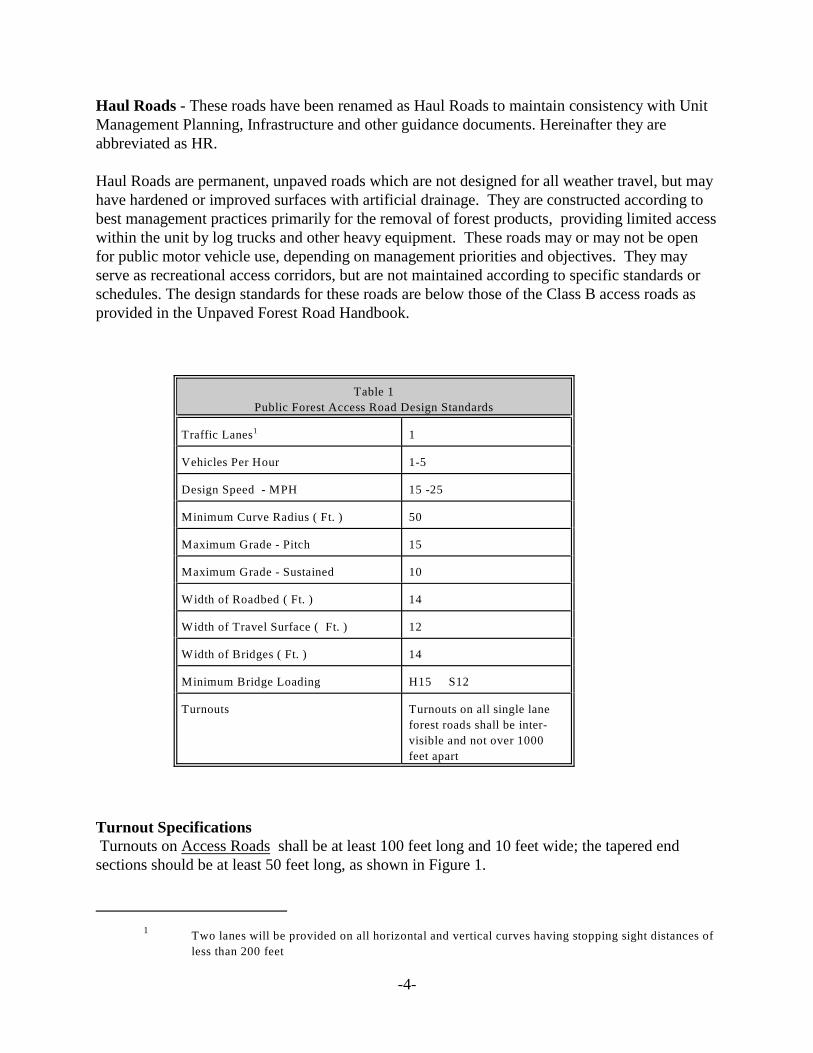
Table 1
Public Forest Access Road Design Standards
Traffic Lanes 1 1
Vehicles Per Hour 1-5
Design Speed - MPH 15 -25
Minimum Curve Radius ( Ft. ) 50
Maximum Grade - Pitch 15
Maximum Grade - Sustained 10
Width of Roadbed ( Ft. ) 14
Width of Travel Surface ( Ft. ) 12
Width of Bridges ( Ft. ) 14
Minimum Bridge Loading H15 S12
Turnouts Turnouts on all single lane
forest roads shall be inter-
visible and not over 1000
feet apart
Turnout Specifications Turnouts on Access Roads shall be at least 100 feet long and 10 feet wide; the tapered end sections should be at least 50 feet long, as shown in Figure 1.
1 Two lanes will be provided on all horizontal and vertical curves having stopping sight distances of
less than 200 feet
-4
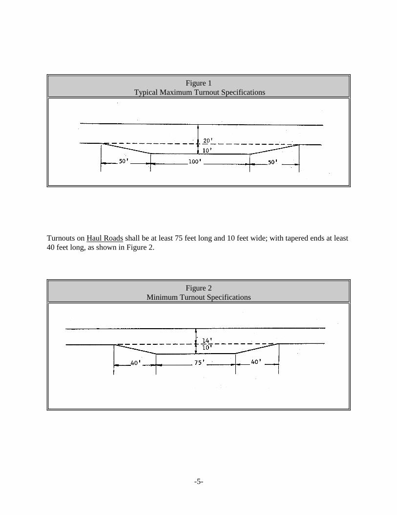
Figure 1 Typical Maximum Turnout Specifications
Turnouts on Haul Roads shall be at least 75 feet long and 10 feet wide; with tapered ends at least 40 feet long, as shown in Figure 2.
Figure 2 Minimum Turnout Specifications
-5
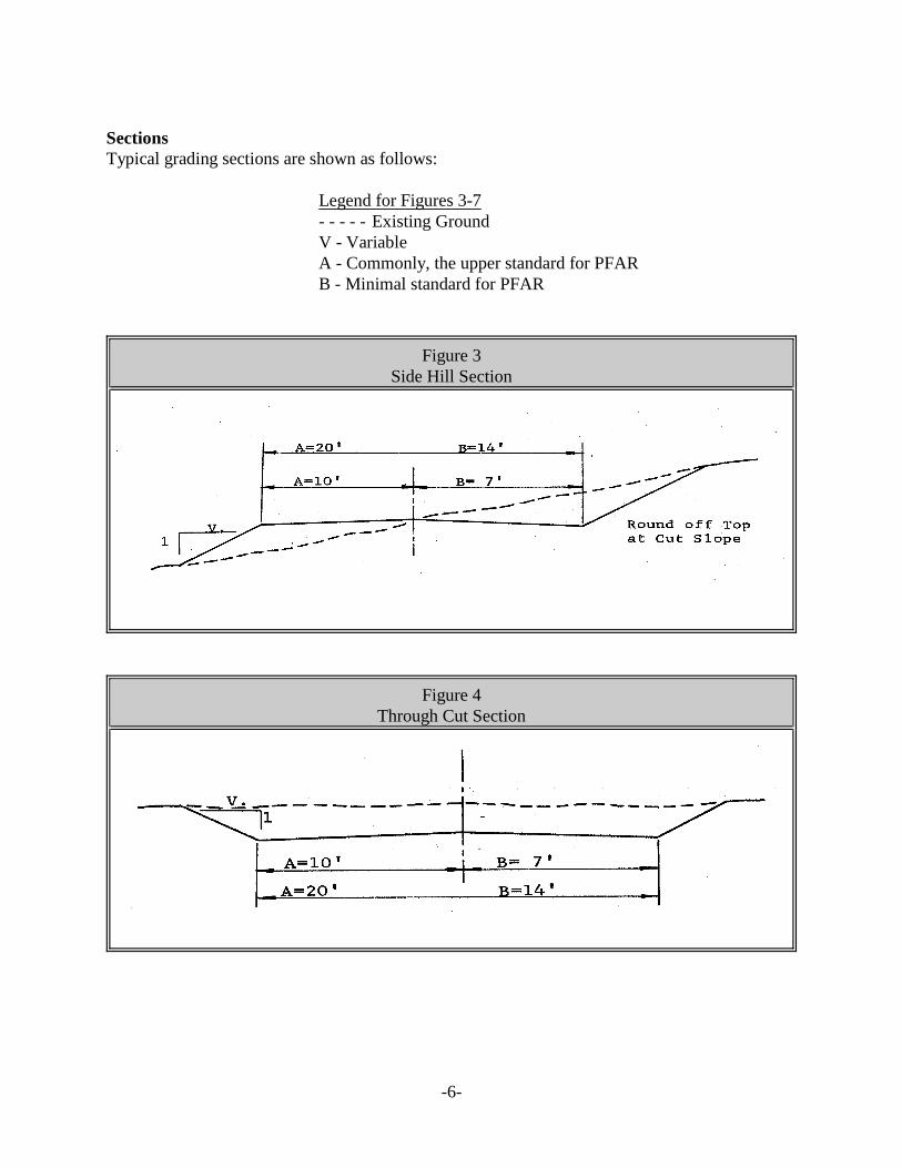
Sections Typical grading sections are shown as follows:
Legend for Figures 3-7 - - - - - Existing Ground V - Variable A - Commonly, the upper standard for PFAR B - Minimal standard for PFAR
Figure 3 Side Hill Section
Figure 4 Through Cut Section
-6
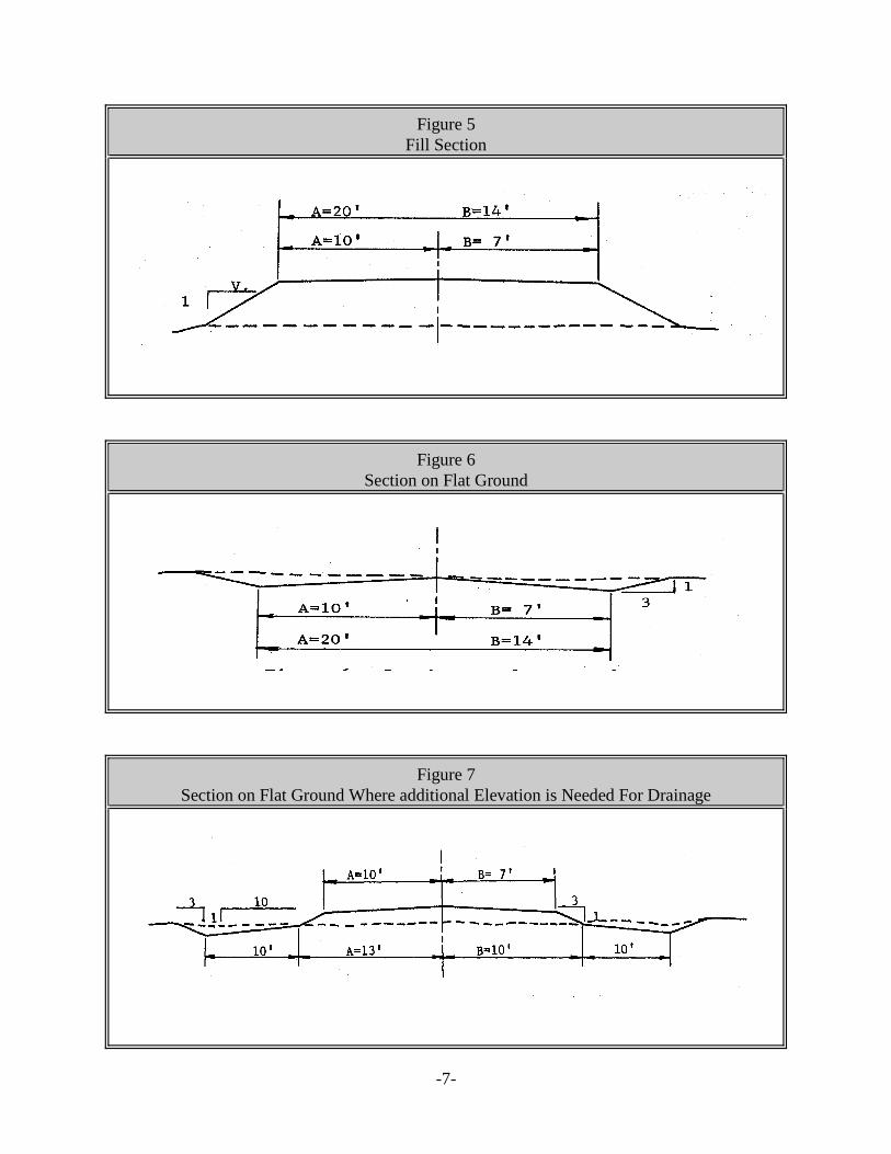
Figure 5 Fill Section
Figure 6 Section on Flat Ground
Figure 7 Section on Flat Ground Where additional Elevation is Needed For Drainage
-7

Surveys
The importance of adequate surveys and careful planning for road construction cannot be overemphasized. Proper attention to these elements is vital to insure that an access system is developed that will meet long-term needs for safe and efficient travel, and that may be constructed and maintained at a minimum cost.
Reconnaissance Survey:
Scope This phase of the survey should consider the following:
1. Terminal points;
2. Intermediate control points;
3. Alternate routes;
4. Gradient,
5. Topographical features.
Field Instrumentation Effective survey, design, layout and construction is dependent upon the use of field instruments to assess, record, plan and execute road construction. These instruments include hand or staff compass, abney level, hand or tripod level with rod, clinometer, transit or most recently Global Positioning Systems technologies. Whatever series of instruments are selected, care should be exercised to ensure suitable precision and relocatable accuracies can be obtained.
Preparation For Field Reconnaissance Prior to making the field reconnaissance, all available information about the area should be obtained. This will include mapping and other data resources which depict topography, vegetative cover, land boundary and forest inventory. U.S.G.S. maps, aerial photos, property maps and inventory maps, or GIS spatial data resources are available to provide the necessary planning information.
Selection of Possible Routes State property lines, terminal points and control points should be plotted and a suitable map produced which highlights pertinent information. A route is then tentatively plotted that will satisfy the requirements of grade, location, control points and economic construction. Alternate routes may also be plotted for later field evaluation.
Field Reconnaissance With the aid of a field instruments, check the tentatively-selected route or routes to ascertain that the terminal points may be connected, through the control points, within the limits of allowable
-8
grades. During the field reconnaissance all factors that have a bearing on the road location and construction, such as soils, drainage, stream crossings, problem areas and general topography should be carefully noted, and can be compared to other limiting factors discovered during the reconnaissance or preliminary assessment phase.
Location Surveys:
Preliminary Location Survey After the best possible route has been selected, based on information learned during the reconnaissance, a preliminary location survey of this route will be made.
Field Method Using field instruments, locate a trial center line using plastic flagging tape or other suitable material. Make necessary adjustments dictated by previously selected control points and grade requirements. Note radii of curves, and adjust tentative center line when necessary. Plot the tentative center line as a Plan and Profile, and adjusting the center line where necessary to give the best alignment and grade.
Final Location Survey:
Center Line Stakes When a final center line location has been selected, set center line stakes at 50 or 100 foot intervals, and mark the stakes to show the total distance from the start of the road (e.g. - Sta. 10+50). Other stakes may be required at critical points on the center line, such as culvert locations, changes in grade, turnouts, etc. Use field instruments to obtain alignment and bearing of the final center line, and distances.
Leveling Elevations for each station can be obtained with field instruments. Establish bench marks not less than 1,000 feet apart for reference during construction. Where possible, bench marks should be established outside the right-of-way to be cleared, to prevent destruction during the clearing operation.
Slope Stakes The location of slope stakes, and right-of-way clearing lines can be determined by taking readings at each station on the final center line to obtain the percentage of slope at right angles to the center line. Slope stakes are required only on side hill construction having slopes in excess of 20%.
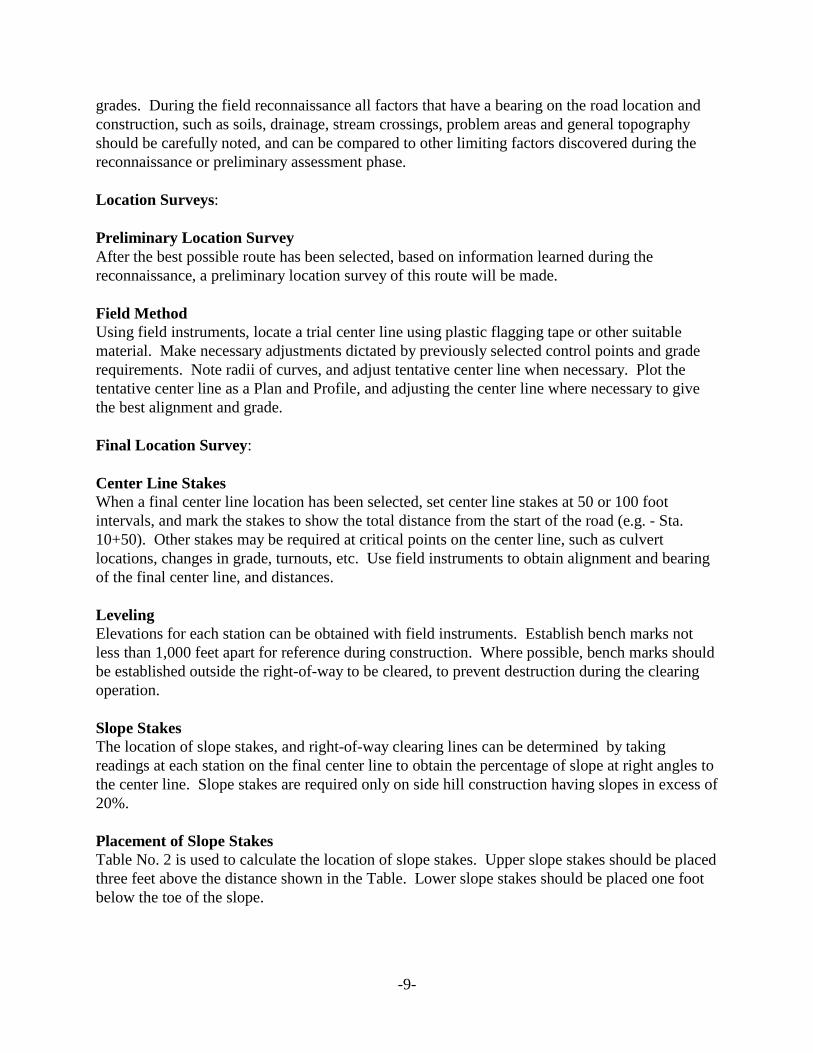
Placement of Slope Stakes Table No. 2 is used to calculate the location of slope stakes. Upper slope stakes should be placed three feet above the distance shown in the Table. Lower slope stakes should be placed one foot below the toe of the slope.
-9
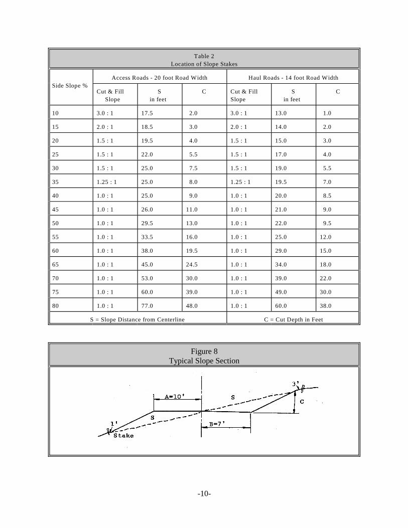
Table 2
Location of Slope Stakes
Side Slope %
Access Roads - 20 foot Road Width Haul Roads - 14 foot Road Width
Cut & Fill
Slope
S
in feet
C Cut & Fill
Slope
S
in feet
C
10 3.0 : 1 17.5 2.0 3.0 : 1 13.0 1.0
15 2.0 : 1 18.5 3.0 2.0 : 1 14.0 2.0
20 1.5 : 1 19.5 4.0 1.5 : 1 15.0 3.0
25 1.5 : 1 22.0 5.5 1.5 : 1 17.0 4.0
30 1.5 : 1 25.0 7.5 1.5 : 1 19.0 5.5
35 1.25 : 1 25.0 8.0 1.25 : 1 19.5 7.0
40 1.0 : 1 25.0 9.0 1.0 : 1 20.0 8.5
45 1.0 : 1 26.0 11.0 1.0 : 1 21.0 9.0
50 1.0 : 1 29.5 13.0 1.0 : 1 22.0 9.5
55 1.0 : 1 33.5 16.0 1.0 : 1 25.0 12.0
60 1.0 : 1 38.0 19.5 1.0 : 1 29.0 15.0
65 1.0 : 1 45.0 24.5 1.0 : 1 34.0 18.0
70 1.0 : 1 53.0 30.0 1.0 : 1 39.0 22.0
75 1.0 : 1 60.0 39.0 1.0 : 1 49.0 30.0
80 1.0 : 1 77.0 48.0 1.0 : 1 60.0 38.0
S = Slope Distance from Centerline C = Cut Depth in Feet
Figure 8 Typical Slope Section
-10
Right-of-Way Clearing Add 3' to slope distance for Upper Slope; add 1' to Lower Slope
Grading of Side Slopes Where the ground line has a gradient of up to 10%, side slopes will be graded to 3:1. A ground line slope of 10% to 30% will require grading of the side slope to 1 ½ :1. A ground line slope of over 40% will be graded 1:1. There will be a transition between 30% and 40% slopes from 1 ½ :1 to 1:1 for cut and fill slopes.
Construction Surveys
Offset Stakes Offset stakes will be set from the center line stakes at regular intervals, not over 500 feet apart, so that the center line can be determined and re-established when center line stakes have been knocked out in construction. Offset stakes should be set 30 feet or more from, and at right angles to, the center line stakes, and marked as follows: Sta. 10+50 30' to center line. They should be set on each side of the center line where they will not be disturbed in the construction process. The Point of Intersection (P.I.) and the Point of Tangents on all curves should be referenced in the same manner.
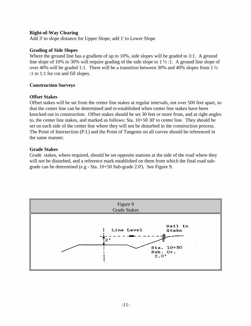
Grade Stakes Grade stakes, where required, should be set opposite stations at the side of the road where they will not be disturbed, and a reference mark established on them from which the final road sub-grade can be determined (e.g - Sta. 10+50 Sub-grade 2.0'). See Figure 9.
Figure 9 Grade Stakes
-11
Horizontal Curves
The center line of a road consists of a series of straight lines connected by curves. Horizontal curves on all forest roads will be laid out as the arc of a circle having a pre-selected radius. For best alignment, the largest radius possible should be selected, consistent with topographic limitations and the economics of construction. In no case will a radius be used which is less than a minimum shown in Table 1.
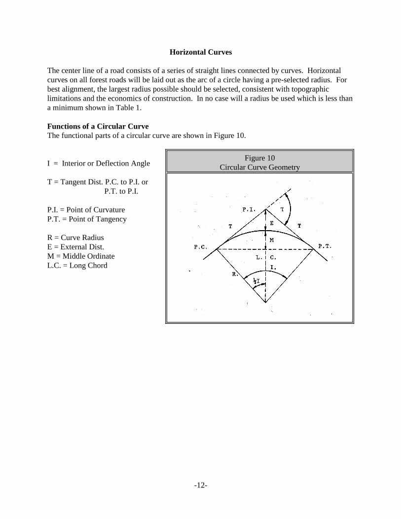
Functions of a Circular Curve The functional parts of a circular curve are shown in Figure 10.
I = Interior or Deflection Angle
T = Tangent Dist. P.C. to P.I. or P.T. to P.I.
P.I. = Point of Curvature P.T. = Point of Tangency
R = Curve Radius E = External Dist. M = Middle Ordinate L.C. = Long Chord
Figure 10 Circular Curve Geometry
-12
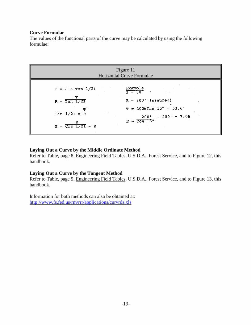
Curve Formulae The values of the functional parts of the curve may be calculated by using the following formulae:
Figure 11 Horizontal Curve Formulae
Laying Out a Curve by the Middle Ordinate Method Refer to Table, page 8, Engineering Field Tables, U.S.D.A., Forest Service, and to Figure 12, this handbook.
Laying Out a Curve by the Tangent Method Refer to Table, page 5, Engineering Field Tables, U.S.D.A., Forest Service, and to Figure 13, this handbook.
Information for both methods can also be obtained at: http://www.fs.fed.us/rm/rrr/applications/curvrds.xls
-13
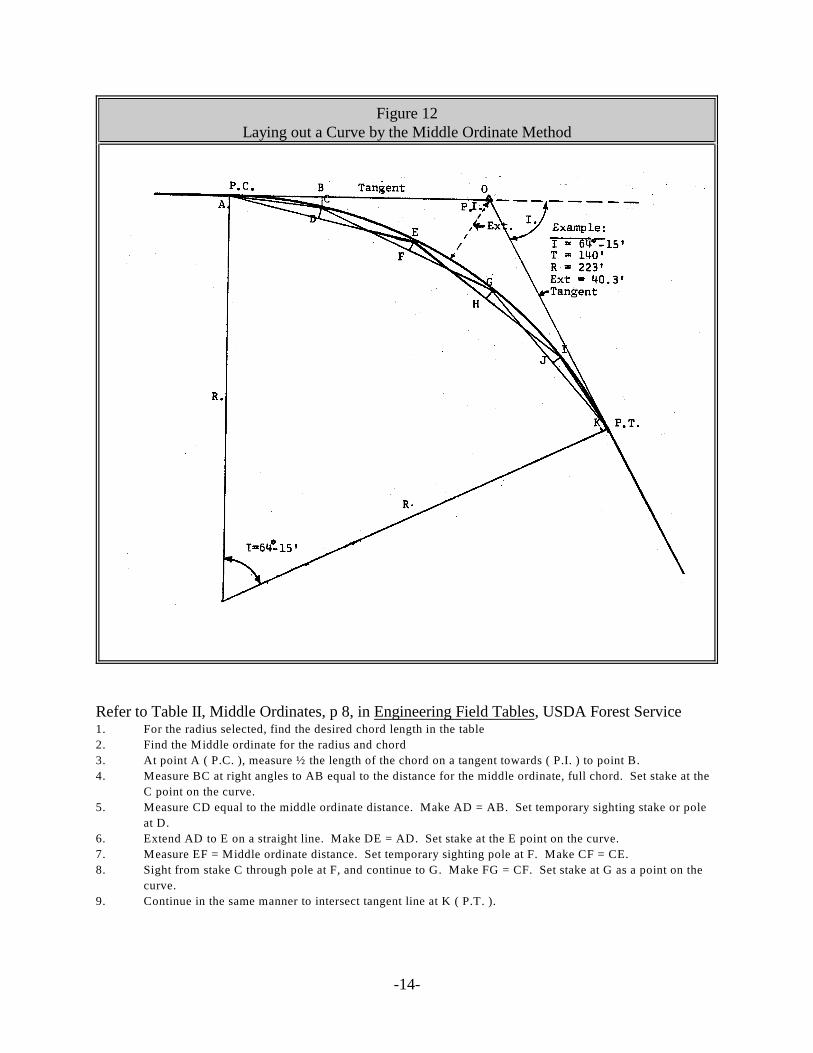
Figure 12 Laying out a Curve by the Middle Ordinate Method
Refer to Table II, Middle Ordinates, p 8, in Engineering Field Tables, USDA Forest Service 1. For the radius selected, find the desired chord length in the table
2. Find the Middle ordinate for the radius and chord
3. At point A ( P.C. ), measure ½ the length of the chord on a tangent towards ( P.I. ) to point B.
4. Measure BC at right angles to AB equal to the distance for the middle ordinate, full chord. Set stake at the
C point on the curve.
5. Measure CD equal to the middle ordinate distance. Make AD = AB. Set temporary sighting stake or pole
at D.
6. Extend AD to E on a straight line. Make DE = AD. Set stake at the E point on the curve.
7. Measure EF = Middle ordinate distance. Set temporary sighting pole at F. Make CF = CE.
8. Sight from stake C through pole at F, and continue to G. Make FG = CF. Set stake at G as a point on the
curve.
9. Continue in the same manner to intersect tangent line at K ( P.T. ).
-14
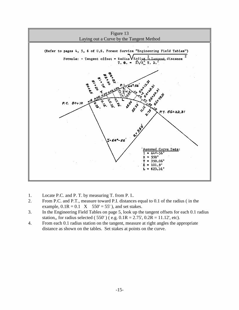
Figure 13 Laying out a Curve by the Tangent Method
1. Locate P.C. and P. T. by measuring T. from P. I.. 2. From P.C. and P.T., measure toward P.I. distances equal to 0.1 of the radius ( in the
example, 0.1R = 0.1 X 550' = 55' ), and set stakes. 3. In the Engineering Field Tables on page 5, look up the tangent offsets for each 0.1 radius
station,, for radius selected ( 550' ) ( e.g. 0.1R = 2.75', 0.2R = 11.12', etc). 4. From each 0.1 radius station on the tangent, measure at right angles the appropriate
distance as shown on the tables. Set stakes at points on the curve.
-15
Vertical Curves
The parabolic vertical curve is used in connecting different rates of grade on a profile. The parabola is used because the elevations can be computed more easily for points on a parabola than for points on a circular arc.
Elements of a Parabolic Vertical Curve The elements are:
g1 = incoming grade in percent
g2 = outgoing grade in percent
P.V.I. = Point of Vertical Curvature
P.V.T. = Point of Vertical Tangent
L = Length of Curve
Minimum Length of a Vertical Curve To insure that sight distances are adequate to allow for safe travel, standards have been set that place minimums on the length of the vertical curve. These minimums, based on the change in grade, are shown in Table No. 3. They apply on all “summit” curves, where the road crests a hill. Under normal circumstances they will not apply on “sag” curves.
Minimum Lengths of Vertical Curves for Forest Roads
Definitions: g1 = incoming or approach grade in per cent
g2 = outgoing or departing grade in per cent
g2 - g1 = change in grade in per cent (neglect sign)
L = minimum length of vertical curve in feet
-16
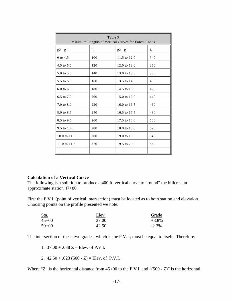
Table 3
Minimum Lengths of Vertical Curves for Forest Roads
g2 - g 1 L g2 - g1 L
0 to 4.5 100 11.5 to 12.0 340
4.5 to 5.0 120 12.0 to 13.0 360
5.0 to 5.5 140 13.0 to 13.5 380
5.5 to 6.0 160 13.5 to 14.5 400
6.0 to 6.5 180 14.5 to 15.0 420
6.5 to 7.0 200 15.0 to 16.0 440
7.0 to 8.0 220 16.0 to 16.5 460
8.0 to 8.5 240 16.5 to 17.5 480
8.5 to 9.5 260 17.5 to 18.0 500
9.5 to 10.0 280 18.0 to 19.0 520
10.0 to 11.0 300 19.0 to 19.5 540
11.0 to 11.5 320 19.5 to 20.0 560
Calculation of a Vertical Curve The following is a solution to produce a 400 ft. vertical curve to “round” the hillcrest at approximate station 47+80.
First the P.V.I. (point of vertical intersection) must be located as to both station and elevation. Choosing points on the profile presented we note:
Sta. Elev. Grade 45+00 37.00 +3.8% 50+00 42.50 -2.3%
The intersection of these two grades; which is the P.V.I.; must be equal to itself. Therefore:
1. 37.00 + .038 Z = Elev. of P.V.I.
2. 42.50 + .023 (500 - Z) = Elev. of P.V.I.
Where “Z” is the horizontal distance from 45+00 to the P.V.I. and “(500 - Z)” is the horizontal
-17
distance from the P.V.I. to 50+00. Proceeding to solve the simultaneous equation:
Subtracting EQ 1 from EQ 2 5.50 + .023 ( 500 - Z ) - .382 = 0 5.50 + 11.50 - 0.61Z = 0 Z = 278.69 Or Sta. Of P. V. I. = 45+00 1 278.69 or 47+78.69
Putting Z back into either equation gives:
Elev. of P. V. I. = 47.59
We now define the elements of a vertical curve: g1 = the incoming grade. In this case + 3.8 % g2 = the outgoing grade. In this case -2.3%
P. V. I. = Point of Vertical Intersection. In this case Station 47+78.69, Elevation 47.59
P. V. C. = Point of Vertical Curvature. This is to be calculated.
P. V. T. = Point of Vertical Tangent. This is to be calculated.
L = Length of curve. In this case the length has been chosen as 400 ft., or 4 stations.
In most vertical curves the P. V. C. and P. V. I. are equidistant from the P. V. I.. Therefore:
Station P. V. C. = 47+78.69
or 45+78.69
Station P. V. T. = 47+78.69 +
or 49 + 78.69
The corresponding elevations:
Elevation P. V. C. = 47.59 - 200 x .038 = 39.99
Elevation P. V. T. = 47.59 - 200 x .023 = 42.99
All vertical road curves are parabolas; the general equation is:
y = ax2 + bx + c
-18
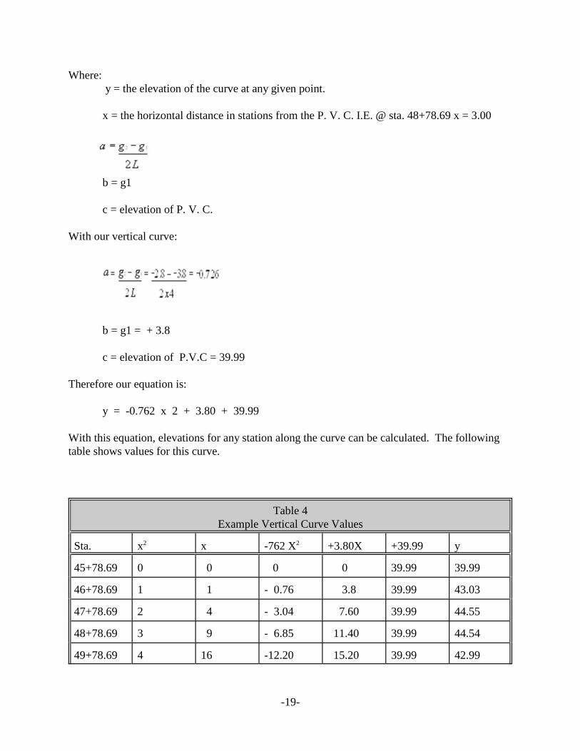
Where: y = the elevation of the curve at any given point.
x = the horizontal distance in stations from the P. V. C. I.E. @ sta. 48+78.69 x = 3.00
b = g1
c = elevation of P. V. C.
With our vertical curve:
b = g1 = + 3.8
c = elevation of P.V.C = 39.99
Therefore our equation is:
y = -0.762 x 2 + 3.80 + 39.99
With this equation, elevations for any station along the curve can be calculated. The following table shows values for this curve.
Table 4 Example Vertical Curve Values
Sta. x2 x -762 X2 +3.80X +39.99 y
45+78.69 0 0 0 0 39.99 39.99
46+78.69 1 1 - 0.76 3.8 39.99 43.03
47+78.69 2 4 - 3.04 7.60 39.99 44.55
48+78.69 3 9 - 6.85 11.40 39.99 44.54
49+78.69 4 16 -12.20 15.20 39.99 42.99
-19
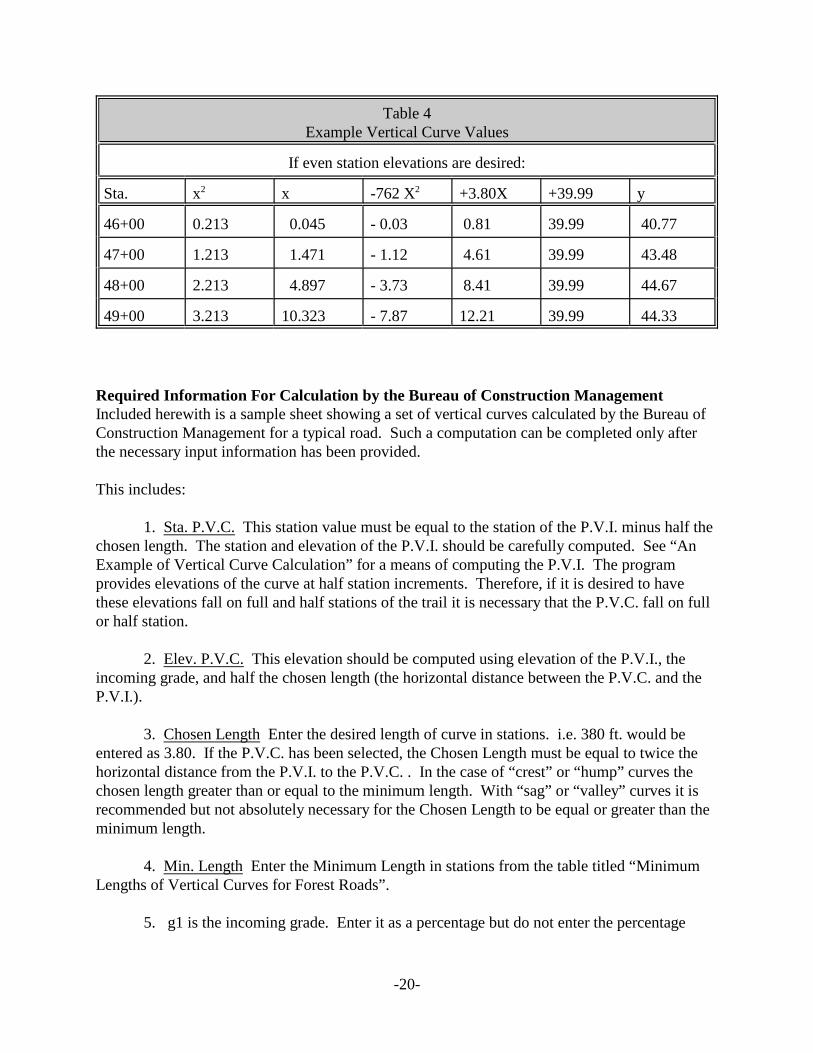
Table 4 Example Vertical Curve Values
If even station elevations are desired:
Sta. x2 x -762 X2 +3.80X +39.99 y
46+00 0.213 0.045 - 0.03 0.81 39.99 40.77
47+00 1.213 1.471 - 1.12 4.61 39.99 43.48
48+00 2.213 4.897 - 3.73 8.41 39.99 44.67
49+00 3.213 10.323 - 7.87 12.21 39.99 44.33
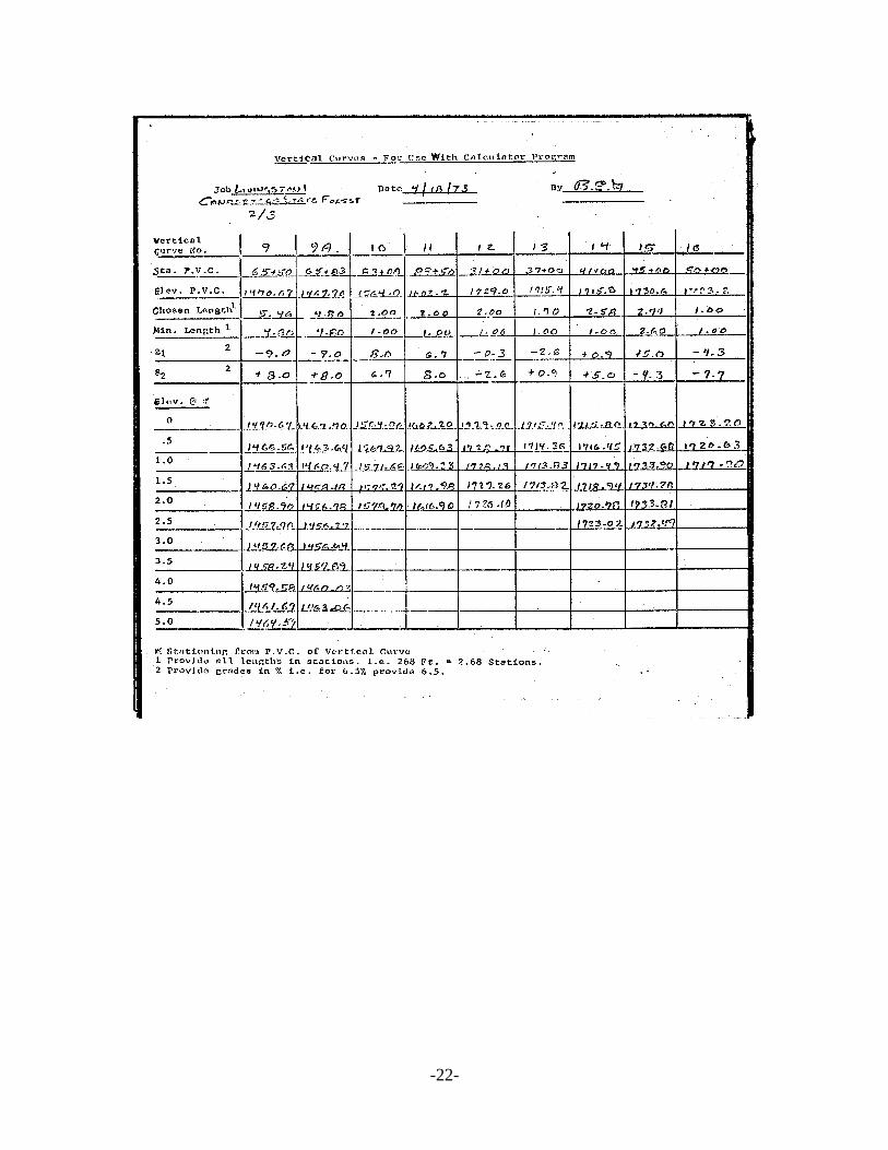
Required Information For Calculation by the Bureau of Construction Management Included herewith is a sample sheet showing a set of vertical curves calculated by the Bureau of Construction Management for a typical road. Such a computation can be completed only after the necessary input information has been provided.
This includes:
1. Sta. P.V.C. This station value must be equal to the station of the P.V.I. minus half the chosen length. The station and elevation of the P.V.I. should be carefully computed. See “An Example of Vertical Curve Calculation” for a means of computing the P.V.I. The program provides elevations of the curve at half station increments. Therefore, if it is desired to have these elevations fall on full and half stations of the trail it is necessary that the P.V.C. fall on full or half station.
2. Elev. P.V.C. This elevation should be computed using elevation of the P.V.I., the incoming grade, and half the chosen length (the horizontal distance between the P.V.C. and the P.V.I.).
3. Chosen Length Enter the desired length of curve in stations. i.e. 380 ft. would be entered as 3.80. If the P.V.C. has been selected, the Chosen Length must be equal to twice the horizontal distance from the P.V.I. to the P.V.C. . In the case of “crest” or “hump” curves the chosen length greater than or equal to the minimum length. With “sag” or “valley” curves it is recommended but not absolutely necessary for the Chosen Length to be equal or greater than the minimum length.
4. Min. Length Enter the Minimum Length in stations from the table titled “Minimum Lengths of Vertical Curves for Forest Roads”.
5. g1 is the incoming grade. Enter it as a percentage but do not enter the percentage
-20
sign. -3.8% should be entered -3.8. The sign of the grade is + if the grade is uphill as the station increase. The sign of the grade is - if the grade is downhill as the stations increase.
6. g2 if the outgoing grade. The instructions for g1 apply here also.
When the above information is supplied on the form elevations of the curve at half station, increments from including the P.V.C. to the last full or half station before the P.V.T. will be provided. If the P.V.T. falls on a full or half station, its elevation will be the last provided.
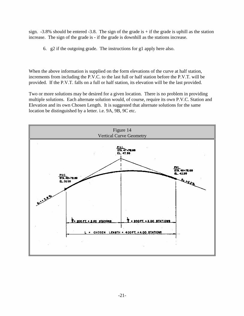
Two or more solutions may be desired for a given location. There is no problem in providing multiple solutions. Each alternate solution would, of course, require its own P.V.C. Station and Elevation and its own Chosen Length. It is suggested that alternate solutions for the same location be distinguished by a letter. i.e. 9A, 9B, 9C etc.
Figure 14 Vertical Curve Geometry
-21
-22

Figure 15 Vertical Curve Data Sheet
Job___________ Date__________ By ___________
Location_____________________________________
Vertical Curve No.
Sta. P.V.C
Elev. P.V.C
Chosen Length1
Min. Length1
g1 2
g2 2
Elev. @ * 0
0.5
1.0
1.5
2.0
2.5
3.0
3.5
4.0
4.5
5.0
* Stationing from P.V.C. of Vertical Curve Provide all lengths in Stations, I.E. 268 Ft. = 2.68 Stations 1
2 Provide grades in percent I.E. for 6.5% provide 6.5
-23
Project Plans
Plan and Profile A Plan and Profile is required for each forest road. This will be prepared from survey notes for the final center line survey, and will be drawn on Federal Aid Sheets, Plan and Profile Paper, size 22" x 36". The plan and profile of the section of road represented should appear on the same sheet.
Scale
Horizontal Scale - 1 inch = 100 feet Vertical Scale - 1 inch = 10 feet
Required Information to be Shown There should be sufficient data on the Plan and Profile sheets to permit construction in the field. Alignment, curve data, grades, location and size of drainage structures, turnouts and typical road sections should be shown. See Figure 13. For curve calculations it is best to assume an appropriate curve radius and calculate other data by use of the applicable formulae.
Approval of the Plan and Profile The completed Plan and Profile should be forwarded to the Bureau of State Land Management, who in turn will arrange for an engineering review of the sheets by the Bureau of Design and Construction. The purpose of this review is to insure that standards have been adhered to, all necessary information has been provided, and that all calculations are correct. Upon approval of the Plan and Profile, copies will be made and forwarded to the appropriate field office. Major construction should not commence until the plan and profile has been approved.
Permits A necessary component in the planning process is to identify the need for, and obtain, any applicable permits. Additional planning may be required to comply with a particular permit. For example, a Storm water Pollution prevention plan may need to be developed if a SPEDES permit is required
Drainage
Surface Drainage The removal of surface water from forest roads, and adequate provision for drainage is a most important part of the planning and construction process. Proper attention given in the planning stage to drainage will minimize later erosion and maintenance problems. Removal of water may be accomplished by crowning of the road surface, cross drainage by culvert pipes placed at regular intervals, water bars on Haul roads, and run-off channels.
-24
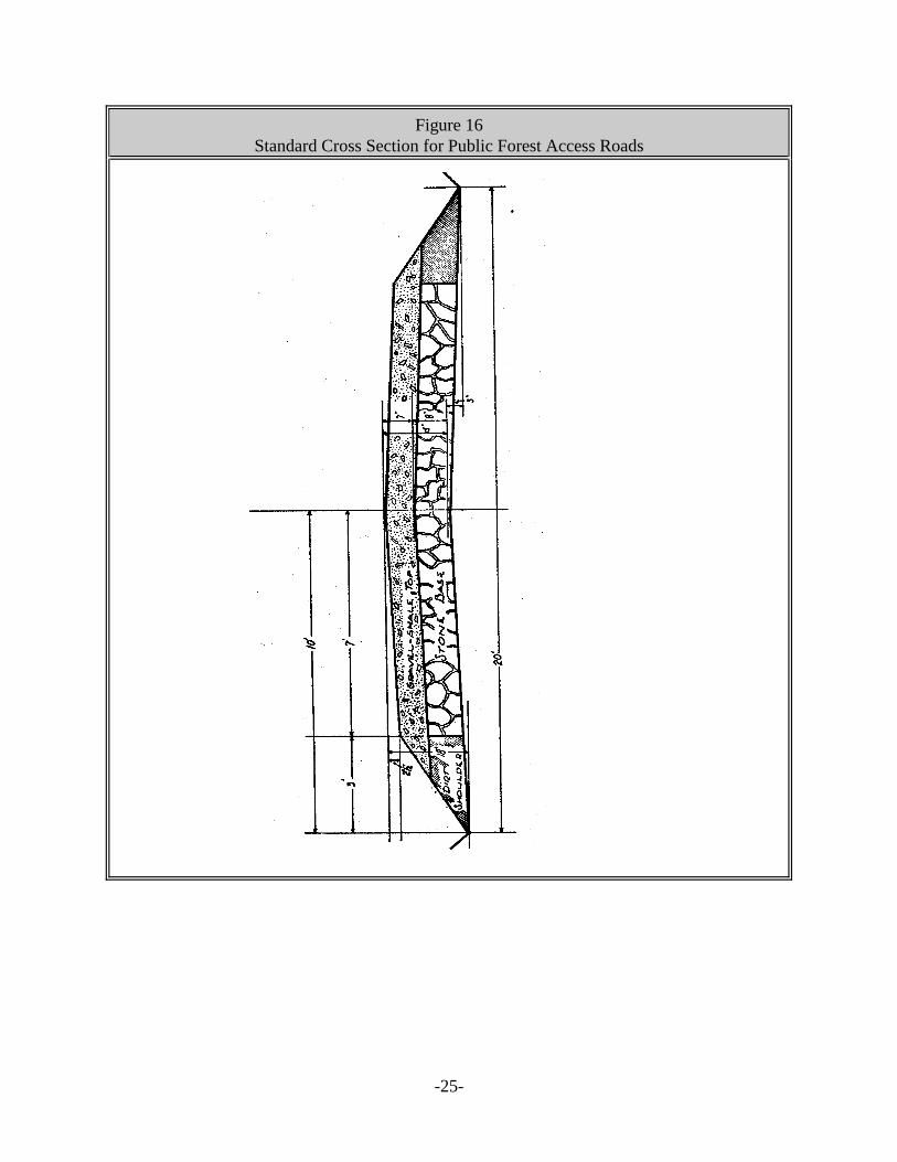
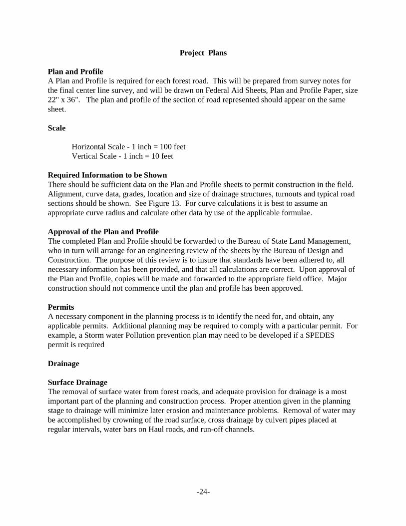
Figure 16 Standard Cross Section for Public Forest Access Roads
-25
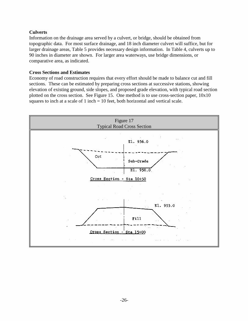
Culverts Information on the drainage area served by a culvert, or bridge, should be obtained from topographic data. For most surface drainage, and 18 inch diameter culvert will suffice, but for larger drainage areas, Table 5 provides necessary design information. In Table 4, culverts up to 90 inches in diameter are shown. For larger area waterways, use bridge dimensions, or comparative area, as indicated.
Cross Sections and Estimates Economy of road construction requires that every effort should be made to balance cut and fill sections. These can be estimated by preparing cross sections at successive stations, showing elevation of existing ground, side slopes, and proposed grade elevation, with typical road section plotted on the cross section. See Figure 15. One method is to use cross-section paper, 10x10 squares to inch at a scale of 1 inch = 10 feet, both horizontal and vertical scale.
Figure 17 Typical Road Cross Section
-26
Table 5 Round Culvert Sizing
Size of round culvert pipe needed for 2.5 inch per hour rainfall
Acres in
Drainage
Area
Impervious
100%
runoff
Steep Slopes/
Heavy Soils
Moderate Slopes/
Heavy to Light soils
+ Dense Cover
Gentle slopes
Agricultural soils
Agricultural cover
Flatland/
Previous
soils
C = 1.0 C = 0.80 C = 0.70 C = 0.60 C = 0.50 C = 0.40 C = 0.30 C = 0.20
Required Culvert Cross Sectional Size
2 15 15 15 15 15 15 15 15
4 18 15 15 15 15 15 15 15
6 18 18 18 15 15 15 15 15
8 24 24 18 18 18 15 15 15
10 24 24 24 18 18 18 15 15
20 30 30 30 24 24 24 18 15
40 42 36 36 36 30 30 24 18
60 48 42 42 42 36 36 30 24
80 54 48 48 42 42 36 30 24
100 60 54 54 48 48 42 36 30
150 72 66 60 54 54 48 42 36
200 78 72 66 60 60 54 48 36
250 84 78 72 66 60 54 48 42
300 90 84 78 72 72 60 54 42
400 8 x 7 90 84 78 72 66 60 48
500 10 x 7 9 x 6 90 84 78 72 60 54
700 10 x 9 10 x 7 10 x 6 10 x 5 90 84 72 60
1000 10 x 12 10 x 9 10 x 8 10 x 7 10 x 6 90 78 66
Table adapted from Permanent Logging Roads handbook, U.S. Forest Service
Based upon Talbots formula A = C /M3
A = Area of the drainage basin.
C = Constant factor based on slope, soil absorptive capacity and cover.
M = Area in square feet of waterway required.
No culverts smaller than 15" will be used
-27
Calculation of Yardage from Cross Section The area of each cross section in square feet can be determined by a planimeter. To obtain volumes in cubic yards, multiply the average cross section area (sq. ft.) of two successive stations by the distance (ft.) between the stations and divide the result by 27.
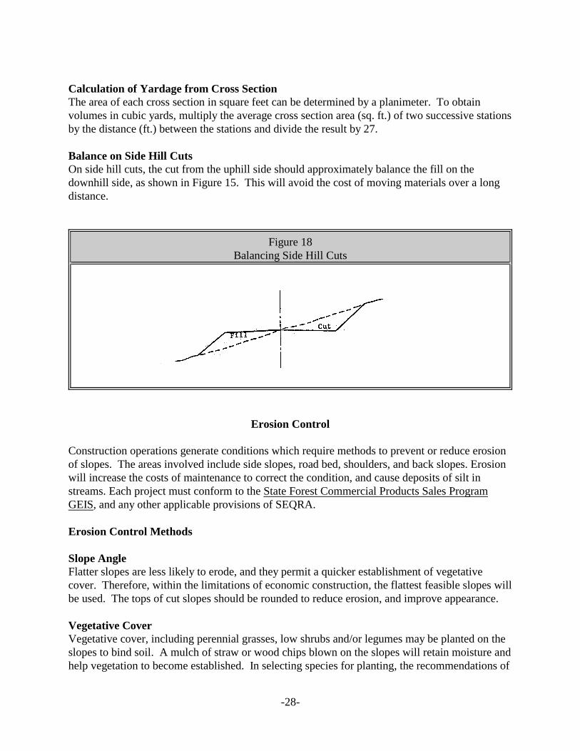
Balance on Side Hill Cuts On side hill cuts, the cut from the uphill side should approximately balance the fill on the downhill side, as shown in Figure 15. This will avoid the cost of moving materials over a long distance.
Figure 18 Balancing Side Hill Cuts
Erosion Control
Construction operations generate conditions which require methods to prevent or reduce erosion of slopes. The areas involved include side slopes, road bed, shoulders, and back slopes. Erosion will increase the costs of maintenance to correct the condition, and cause deposits of silt in streams. Each project must conform to the State Forest Commercial Products Sales Program GEIS, and any other applicable provisions of SEQRA.
Erosion Control Methods
Slope Angle Flatter slopes are less likely to erode, and they permit a quicker establishment of vegetative cover. Therefore, within the limitations of economic construction, the flattest feasible slopes will be used. The tops of cut slopes should be rounded to reduce erosion, and improve appearance.
Vegetative Cover Vegetative cover, including perennial grasses, low shrubs and/or legumes may be planted on the slopes to bind soil. A mulch of straw or wood chips blown on the slopes will retain moisture and help vegetation to become established. In selecting species for planting, the recommendations of
-28

the Regional Supervisor of Fish and Wildlife will be sought to insure proper consideration for wildlife values.
Rip-Rap Where the slope is likely to come in contact with flowing water, loose rock rip-rap protection is needed to prevent erosion. This is particularly the case with culverts, and along bridge wing-walls.
Road Crown Roads will be crowned 1/4 inch per foot of road width to drain surface water from the road center towards the shoulders.
Streams Roads will not be constructed in stream channels. A filter strip with a minimum width of 150 feet will be maintained where a road parallels a stream. When required, stream crossings will be made at right angles, insofar as possible, to minimize siltation and to disturb the stream as little as possible.
-29
Construction
Construction Standards Roads will be constructed to the standards as outlined in this handbook. Standards establish the width, grade, alignment and service class of roads to be constructed.
Job Planning and Supervision Roads should be surveyed and planned well in advance of the proposed date of construction. Planning is required at least one year in advance so that the necessary materials and equipment may be ordered, and to obtain the necessary funds. Planning includes a provision for supervision of the project by persons trained and informed in road construction standards and methods.
Safety Full consideration must be given to the use of all appropriate safety measures and equipment. Road construction contains many hazardous situations for which provisions must be made. The use of heavy equipment and explosives, falling and flying objects, and lifting of objects are examples of situations which demand full safety measures to prevent accidents and serious injury.
Safety Standards Applicable Department safety standards will be strictly adhered to during all phases of planning and construction.
Use of Explosives Explosives will be used only under the direction of a competent person, licensed by the New York State Department of Labor to engage in such work. All applicable State and Federal laws relating to the use, possession, storage and transport of explosives will be observed. “The Blaster’s Handbook”, prepared by the E.I. DuPont Company, should be used as a guide in all blasting operations.
Right-Of-Way Clearing Clearing the right-of-way for road construction will be accomplished after the final center line location has been determined and staked in the field. This includes center line stakes, offset stakes, and slope stakes where required.
Protection of Stakes Workers engaged in the clearing operation should be instructed to use special care to insure that stakes are not damaged or destroyed as a result of their activities.
Width of Clearing Width of the right-of-way to be cleared will be determined by the class of the road being constructed, and the topography.
-30
Disposal of Cut Material Insofar as possible, brush from tops should be chipped and scattered on the site. Useable materials will be cut and piled along the sides of the right-of-way for sale or other use. If it is not feasible to chip tops they should be pulled at least 30 feet from the edge of the road right-of-way, and lopped and scattered close to the ground. This will improve the aesthetics along the road and aid in the deterioration of the woody material.
Stumps Stumps of large trees can be blasted to facilitate removal and to reduce the soil clinging to them. If necessary to remove trees on the lower side of side hill cuts, the low-cut stumps may be left and covered with at least one foot of fill. Stumps will be disposed of either in stump dumps along the right-of-way, righted and scattered unobtrusively outside the right-of-way, or trucked off. Efforts should be made to reduce the visibility of removed stumps from the road.
Grading Rough grading can be best accomplished with a bulldozer. After the rough grading is completed, a grader will smooth out the road to proper grade, prepare the sub-grade, pull up earth shoulders to contain the surfacing material, and smooth out the side slopes. The ditch line can also be cleared with a grader to give a uniform slope.
Grade Stakes Grade stakes, as required, should be set at the side of the road where they will not be disturbed. Stationing and the sub-grade elevation reference point will be marked on all grade stakes.
Rock Excavation Rock excavation is costly and should be avoided wherever possible. If conditions require that rock excavation be done, the depth of excavation needed should be calculated, and arrangements made for the necessary drilling and blasting. Depth should be sufficient to permit at least one foot of fill material and 8 inches of surfacing material over the final rock surface. Side slopes of rock cut should be no more than 0.50 : 1.
Sub-surface Drainage Sub-base and fill material should be of such a nature that it will permit sub-drainage of the road to the ditch line. This would include rock fill, coarse gravel, or coarse shale. Where seepage points occur, water should be conducted through a channel of rock weep-drains to the ditch line. In severe cases, perforated tile should be used.
Surface Drainage Road crowns, ditches, culverts and bridges should be designed to take care of the surface drainage. A properly crowned road will conduct water to the ditch line and prevent rutting. Ditches carry water alongside the road until it reaches a culvert, a lead-off channel, or a stream. Ditches should have no less than a 1% slope to drain properly.
Culverts Culverts will take care of most surface drainage until the drainage area exceeds 400 acres.
-31
Waterway requirements in excess of 44 square feet will call for a bridge to handle the flow. Use Table No. 4 to calculate the size of drainage structure required. Culverts will be required at low points, stream crossings, and spaced not over 300 feet apart on side hill cuts to provide cross drainage.
Culvert Installation Culverts should be installed according to the following guidelines:
1. Installation should equal or exceed slightly the slope of the stream or ditch which flows through the culvert.
2. Put in a cushion of sand or fine gravel to minimum depth of 6 inches in the bottom of the trench dug for the culvert. Put grade stakes at upper and lower end (minimum slope 2%). Make center of cushion approximately 2 inches higher than grade to allow for settling of the pipe when covered.
3. Culverts should be 40% of length uphill from center line; 60% downhill from center line.
4. Fine sand or gravel should be tamped in all around and over the culvert. Pipes should be covered with fill to a depth at least equal to their diameter.
5. Culvert pipes should be angled downhill from a right angle on side hill drainage.
6. Add two feet to establish length of culvert pipe needed.
7. If road crosses a stream at an angle, culvert pipes should be skewed to be in line with stream flow.
8. Avoid twin culverts. Use a larger size single culvert, or “squash” type culvert if elevation is a problem.
9. Make drop inlets or catch basins at culvert inlets to intercept water, and to protect inlet. Use dry masonry or concrete masonry as situation requires. Culvert outlets should be protected by culvert head walls or stone rip-rap. See Figures 17 and 18.
-32
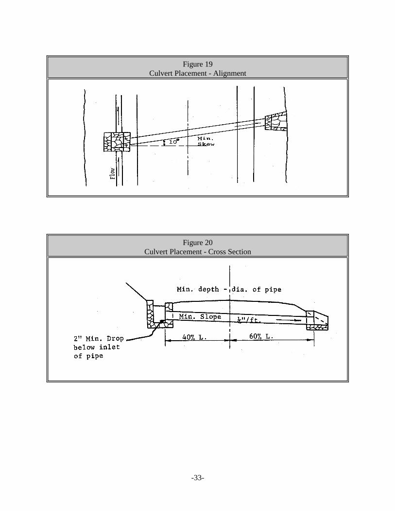
Figure 19 Culvert Placement - Alignment
Figure 20 Culvert Placement - Cross Section
-33