dec 0 2ocdimage.emnrd.state.nm.us/imaging/filestore/hobbs/wf/258273/... · rkb: 3662' gl:...
TRANSCRIPT

t f Oc Form 3160-5 UNITED STATES H ° b f a s
(August 2007) DEPARTMENT OF THE INTERIOR BUREAU OF LAND MANAGEMENT
SUNDRY NOTICES AND REPORTS ON WELLS Do not use this form for proposals to drill or to re-enter an
abandoned well. Use Form 3160-3 (APD) for such pro^o^/gg OCD
FORM APPROVED OMB No. 1004-0137 Expires: July 31, 2010
t f Oc Form 3160-5 UNITED STATES H ° b f a s
(August 2007) DEPARTMENT OF THE INTERIOR BUREAU OF LAND MANAGEMENT
SUNDRY NOTICES AND REPORTS ON WELLS Do not use this form for proposals to drill or to re-enter an
abandoned well. Use Form 3160-3 (APD) for such pro^o^/gg OCD
5. Lease Serial No. NM-13276, NM129733, NM84651
t f Oc Form 3160-5 UNITED STATES H ° b f a s
(August 2007) DEPARTMENT OF THE INTERIOR BUREAU OF LAND MANAGEMENT
SUNDRY NOTICES AND REPORTS ON WELLS Do not use this form for proposals to drill or to re-enter an
abandoned well. Use Form 3160-3 (APD) for such pro^o^/gg OCD
6. I f Indian, Allottee or Tribe Name
SUBMIT IN TRIPLICATE- Other instructions on page 2. 7. I f Unit of CA/Agreement, Name and/or No.
L Type of Well Q £ £ \ j I i U H
H Oil Well • Gas Well • Other
7. I f Unit of CA/Agreement, Name and/or No.
L Type of Well Q £ £ \ j I i U H
H Oil Well • Gas Well • Other 8. Well Name and No. ^ Hamon Fed Com A #1H ^
2. Name of Operator IHE^CIVED Legacy Reserves Operating L.P. y
9. API Well No. ^ 30-025-41616 /
3a. Address 3b. Phone No. (include area code) PO Bos 10848 Midland, TX 79702 432-689-5200
10. Field and Pool or Exploratory Area
Teas East; Bone Spring
4. Location of Well (Footage, Sec, T.,Rr,M.. or Survey Description) SHLSec18T20SR34E 200FNL 1010FWL • BHLSec7T20SR34E 330FNL 1980FWL
11. Country or Parish, State
Lea
12. CHECK THE APPROPRIATE BOX(ES) TO INDICATE NATURE OF NOTICE, REPORT OR OTHER DATA
TYPE OF SUBMISSION TYPE OF ACTION
1Y I Notice of Intent
| [ Subsequent Report
I | Final Abandonment Notice
1 1 Acidize
1 I Alter Casing
1 1 Casing Repair
\J\Change Plans
1 1 Convert to Injection
1 1 Deepen
1 1 Fracture Treat
1 1 New Construction
1 1 Plug and Abandon
1 1 Plug Back
1 1 Production (Start/Resume)
1 1 Reclamation
1 1 Recomplete
1 1 Temporarily Abandon
1 1 Water Disposal
1 1 Water Shut-Off
1 I Well Integrity
l ~ l Other
13. Describe Proposed or Completed Operation: Clearly state all pertinent details, including estimated starting date of any proposed work and approximate duration thereof. If the proposal is to deepen directionally or recomplete horizontally, give subsurface locations and measured and true vertical depths of all pertinent markers and zones. Attach the Bond under which the work will be performed or provide the Bond No. on file with BLM/BIA. Required subsequent reports must be filed within 30 days following completion of the involved operations. I f the operation results in a multiple completion or recompletion in a new interval, a Form 3160-4 must be filed once testing has been completed. Final Abandonment Notices must be filed only after all requirements, including reclamation, have been completed and the operator has determined that the site is ready for final inspection.)
Legacy Reserves Operating proposes to re-enter the existing well bore that had been P&A. The well will be entered and the cement will be dressed to 5350'MD. A whipstock will be set and a window milled in the 9.625" casing at 5350' (50' above he 9.625" casing shoe). The well bore will be directional drilled down to the Bone Spring and the well will be horizontal at a depth of 9500'TVD which is in the First Bone Spring Sand. The well bore will be drilled as per the directional plan attached. At TD casing will be run and cemented as per the casing and cementing sections below. Refer to drilling plan for detailed operations.
PSOA, C102, Support Maps, BOP, Choke Manifold, Closed Loop Documents, Rig Layout, H2S plan, Interim Reclamation Plat, Surface use, Certification Letter will all be the same documents as submitted with the original approved APD.
14. I hereby certify that the foregoing is true and correct. Name (Printed/Typed)
Signature
Title Senior Engineer
Date 11/13/2014
THIS SPACE FOR FEDERAL OR STATE OFFICE USE
Approved by
Title $ / A Date Conditions of approval, if any, are attached. Approval of this notice does not warrant or certify that the applicant holds legal or equitable title to those rights in the subject lease which would entitle the applicant to conduct operations thereon.
Title 18 U.S.C. Section 1001 and Title 43 U.S.C. Section 1212, make it a crime for any person knowingly and willfully to make to any department or agency of the United States any false, fictitious or fraudulent statements or representations as to any matter within its jurisdiction.
(Instructions on page 2)
DEC 0 2 2014

Attachment to Form 3160-3
Legacy Reserves Operating Re-Entry Drilling Prognosis
Hamon Fed Com A #1H
Revision date: November 12, 2014
Surface Location:
Bottom Hole:
575,376.80usft N, 724,528.80usft E 200' FNL, 1010' FWL
Section 18, T-20-S, R-34-E Lea County, New Mexico
580,532.95usft N, 725,487.54usft E 330' FNL, 1980' FWL
Section 7, T-20-S, R-34-E Lea County, New Mexico
Planned Total Depth: 9500' TVD h4396' MD
RKB: 3662' GL: 3640'
Preparer: Steve Morris
Legacy Reserves Operating 1 Hamon Fed Com A#1H
i Attachment to Form 3160-3
Contents Article I. General Provisions: 3
Article II. Permit Expiration 3
Article III. Plan of Action 3
Article IV. Estimated Formation Tops (geoprognosis with TVD's adjusted to actual KB): 3
Article V. Pressure Control: 3
Article VI. Casing Program (minimum): 7
Article VII. Cement Program: 7
Section 7.01 5.5" Production Casing 7
Article VIII. Product Descriptions: 8
Article IX. Mud Program: 9
Article X. Mud Monitoring System: 9
Article XI. Logging, Drill stem testing and Coring: 9
Article XII. Bottom Hole: 9
Article XIII. Abnormal Conditions: 9
Article XIV. H2S: 9
Article XV. Directional: 9
Article XVI. Drilling Recorder: 10
Legacy Reserves Operating 2 Hamon Fed Com A#1H
Attachment to Form 3160-3
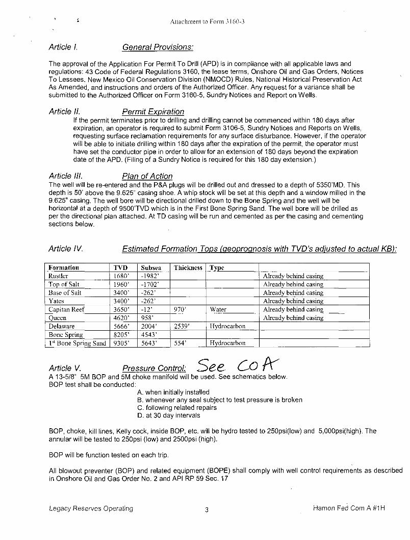
Article I. General Provisions:
The approval of the Application For Permit To Drill (APD) is in compliance with all applicable laws and regulations: 43 Code of Federal Regulations 3160, the lease terms, Onshore Oil and Gas Orders, Notices To Lessees, New Mexico Oil Conservation Division (NMOCD) Rules, National Historical Preservation Act As Amended, and instructions and orders of the Authorized Officer. Any request for a variance shall be submitted to the Authorized Officer on Form 3160-5, Sundry Notices and Report on Wells.
Article II. Permit Expiration If the permit terminates prior to drilling and drilling cannot be commenced within 180 days after expiration, an operator is required to submit Form 3106-5, Sundry Notices and Reports on Wells, requesting surface reclamation requirements for any surface disturbance. However, if the operator will be able to initiate drilling within 180 days after the expiration of the permit, the operator must have set the conductor pipe in order to allow for an extension of 180 days beyond the expiration date of the APD. (Filing of a Sundry Notice is required for this 180 day extension.)
Article III. Plan of Action The well will be re-entered and the P&A plugs will be drilled out and dressed to a depth of 5350'MD. This depth is 50' above the 9.625" casing shoe. A whip stock will be set at this depth and a window milled in the 9.625" casing. The well bore will be directional drilled down to the Bone Spring and the well will be horizontal at a depth of 9500TVD which is in the First Bone Spring Sand. The well bore will be drilled as per the directional plan attached. At TD casing will be run and cemented as per the casing and cementing sections below.
Article IV. Estimated Formation Tops (peopropnosis with TVD's adjusted to actual KB):
Formation TVD Subsea Thickness Type Rustler 1680' -1982' Already behind casing Top of Salt I960' -1702' Already behind casing Base of Salt 3400' -262' Already behind casing Yates 3400' -262' Already behind casing Capitan Reef 3650' -12' 970' Water Already behind casing Queen 4620' 958' Already behind casing Delaware 5666' 2004' 2539' Hydrocarbon Bone Spring 8205' 4543' 1 s t Bone Spring Sand 9305' 5643' 554' Hydrocarbon
Article V. Pressure Control: See O o K A 13-5/8" 5M BOP and 5M choke manifold will be used. See schematics below. BOP test shall be conducted:
A. when initially installed B. whenever any seal subject to test pressure is broken C. following related repairs D. at 30 day intervals
BOP, choke, kill lines, Kelly cock, inside BOP, etc. will be hydro tested to 250psi(low) and 5,000psi(high). The annular will be tested to 250psi (low) and 2500psi (high).
BOP will be function tested on each trip.
All blowout preventer (BOP) and related equipment (BOPE) shall comply with well control requirements as described in Onshore Oil and Gas Order No. 2 and API RP 59 Sec. 17
Legacy Reserves Operating 3 Hamon Fed Com A #1H

CP
Attachment to Form 31.60-3
Minimum Working pressure of the blowout preventer (BOP) and related equipment (BOPE) required for drilling below the 9-5/8 inch intermediate casing show shall be 5000 (5M) psi. 5M system requires an HCR valve, remote kill line ad annular to match. The remote kill line is to be installed prior to testing the system and tested to stack pressure.
The appropriate BLM office shall be notified a minimum of 4 hours in advance for a representative to witness the tests. In a water basin, for all casing strings utilizing slips, these are to be set as soon as the crew and rig are ready and any fallback cement remediation has been done. The casing cut-off and BOP installation can be initiated four hours after installing the slips, which will be approximately six hours after bumping the plug. For those casing strings not using slips the minimum wait time before cut-off is eight hours after bumping the pug. BOP/BOPE testing can begin after cut-off or once cement reaches 500PSI compressive strength (including lead when specified), whichever is greater. However, if the float does not hold, cut-off cannot be initiated until cement reaches 500 psi compressive strength (including lead when specified).
The tests shall be done by an independent service company utilizing a test plug not a cup or J-packer. The operator also has'the option of utilizing an independent tester to test without a plug (i.e. against the casing) pursuant to Onshore Order 2 with the pressure not to exceed 70% of the burst rating for the casing. Any test against the casing must meet the WOC time for water basin (18 hours) or potash (24 hours) or 500 pounds compressive strength, whichever is greater prior to initiating the test (see casing segment as lead cement may be critical item).
a. The results of the test shall be reported to the appropriate BLM office.
b. All Tests are required to be recorded on a calibrated test chart. A copy of the BOP/BOPE test chart and a copy of independent service company test will be submitted to the appropriate BLM office.
c. The BOP/BOPE test shall include a low pressure test from 250 to 300 psi. The test will be held for a minimum of 10 minutes if test is done with a test plug and 30 minutes without a test plug.
JK Co-Flex hose may be used from the BOP to the Choke Manifold. If this is used the manufacture specifications and certifications will be furnished prior to use and be present on location. A variance is requested for the use of the Co-Flex hose. Below are the spec and test certifications.
Legacy Reserves Operating 4 Hamon Fed Com A#1H

Attachment to Form 3160-3
Fluid Technology
Quality Document
QUALITY CONTROL INSPECTION AND TEST CERTIFICATE
CERT. N •: 378
PURCHASER: ConliTech Seattle Co. P.O. N»: 004944
CONTITECH ORDER N°: 498705 HOSE TYPE: 3" ID Choke and Kill Hose
HOSE SERIAL ti°\ 60575 NOMINAL/ ACTUAL LENGTH: 9,14 m /9 ,14 m
W.P. 68,9 MP» 10000 psi TP- 103,4 MPa 15000 PSl Duration: 60 min.
Pressure test with water at
ambient temperature
See attachment. (1 page)
T 1 0 m m = 10 Min.
- > 1 0 m m = 2 0 MPa
COUPLINGS Type Serial N" Quality Heatir
3" coupling with 8925 8930 AISI4130 B2297A
4 1/16" Swivel Flange end A1SI4130 31863
Hub AISI4130 . B2297A
ASSET NUMBER : 66 - 0694 API Spec 16 C
Temperature rate:"B" All melal parts are flawless
We CERTIFY THAT THE ABOVE HOSE HAS BEEN MANUFACTURED IN ACCORDANCE WITH THE TERMS OF THE ORDER INSPECTED AND PRESSURE TESTED A8 ABOVE WITH SATISFACTORY RESULT.
STATEMENT OF CONFORMITY: We hereby certify that the above Items/erjuSpment suppled by us aro in conformity with Ihe terms, conditions and spedtica'Jona of the above Purchaser Order and fta! these Hems/equipment were fabricated Inspected and tested in
accordance with the referenced standards, codes and specifications and meet ma relBvant acceptance criteria and design requirements.
COUNTRY OF ORIGIN HUNGARY/EU
Date:
22. March 2011.
Inspector Quality Control ContlTeeh Rubber
Industrial KfL QaaEty Control Dept.
Legacy Reserves Operating 5 Hamon Fed Com A # 1 H
Attachment to Form 3160-3
AY1ACHMENT OF QUALITY CONTROL INSPECTION AND TEST CERTIFICATE No: 319. 377. 378
Page: Ul
Legacy Reserves Operating 6 Hamon Fed

Attachment to Form 3160-3
A variance is requested to use 1502(15,000psi working pressure) hammer unions downstream of the Choke Manifold used to connect the mud/gas separator and panic line. See attached Choke Manifold drawing.
Article VI. Casing Program (minimum): • *AII casing is new API casing.*
Hole Size Casing Weight lb/ft Grade Conn MD/RKB 20" 120' Existing Casing
16" 13.375" 54.5 J-55 STC 1587' Existing Casing 12.25" 9.625" 40 J-55 LTC 3964' Existing Casing 12.25" 9.625" 40 N80 LTC 5400' Existing Casing 8.5" 5.5" 17 P1.10 GBCD 14396'
Size Collapse psi SF Burst psi SF Tension Klbs SF Max Setting Depth TVD 5.5 7480 1.55 10640 1.29 568 3.06 17000
Article VII. Cement Program:
Section 7.01 5.5" Production Casing
Lead: 0 - 9500' Slurry WT Yield Sx Gallons/ Sack Excess Additives 11.9ppg 2.38cuft/sk 1500 13.22 80%
in open hole Class H (50:50) + Poz (Fly Ash) + 10% bwoc Bentonite II + 5% bwow Sodium Chloride + 5 lbs/sack LCM-1 + 0.005 lbs/sack Static Free + 0.005 gps FP-6L
Tail: 9500-TD Slurry WT Yield Sx Gallons/ Sack Excess Additives 13.2ppg 1.62cuft/sk 1000 9.45 20% Class H (15:61:11)
Poz(FlyAsh):Class H Cement:CSE-2 + 4% bwow Sodium Chloride + 3 lbs/sack LCM-1 + 0.6% bwoc FL-25 + 0.005 gps FP-6L + 0.005% bwoc Static Free
Circulate cement to surface. If cement does not circulate to surface a top squeeze job or casing perforation will be used. As well, a temperature survey or CBL will be performed. Cement volumes will be adjusted proportionately once actual depth is determined and washout from a fluid caliper. n
Legacy Reserves Operating 7 Hamon Fed Com A#1H
Attachment to Form 3160-3
Article VIII. Product Descriptions:
Bentonite II P105
CSE-2 An additive which contributes to low density, high compressive strength development of cement slurries at all temperature ranges. This material also controls free water without the need for standard extenders.
Calcium Chloride A powdered, flaked or pelletized material used to decrease thickening time and increase the rate of strength development.
Cello Flake
Graded (3/8 to 3/4 inch) cellophane flakes used as a lost circulation material.
Class C Cement
Intended for use from surface to 6000 ft., and for conditions requiring high early strength and/or sulfate resistance.
Class H Cement Class H cement is an API type, all-purpose oil well cement which is used without modification in wells up to 8,000 ft. It possesses a moderate sulfate resistance. With the use of accelerators or retarders, it can be used in a wide range of well depths and temperatures. FL-25 An all-purpose salt-tolerant fluid loss additive that provides exceptional fluid loss control across a wide range of temperatures and salinity conditions and remedial cementing applications. FL-52 A water soluble, high molecular weight fluid loss additive used in medium to low density slurries. It is functional from low to high temperature ranges.
FP-6L
A clear liquid that decreases foaming in slurries during mixing.
LCM-1 A graded (8 to 60 mesh) naturally occurring hydrocarbon, asphaltite. It is used as a lost circulation material at low to moderate temperatures and will act as a slurry extender. Cement compressive strength is reduced.
MPA-5
Used to enhanced compressive, tensile, fleural strength development and reduced permeability
Poz (Fly Ash) A synthetic pozzolan, (primarily Silicon Dioxide). When blended with cement, Pozzolan can be used to create lightweight cement slurries used as either a filler slurry or a sulfate resistant completion cement. Sodium Chloride
At low concentrations, it is used to protect against clay swelling.
Sodium Metasilicate An extender used to produce economical, low density cement slurry.
Legacy Reserves Operating 8 Hamon Fed Com A#1H

Attachment to Form 3160-3
Static Free An anti-static additive used to prevent air entrainment due to agglomerated particles. Can be used in Cementing and Fracturing operations to aid in the flow of dry materials.
Article IX. Mud Program: Depth Hole Type MW PV YP WL pH Sol % 5350- KOP 8.5" Cut Brine 8.4-8.6 1-2 1-2 NC 9.5 <1.0 KOP-TD 8.5" Cut Brine 8.9-9.1 4-6 4-6 18-20 9.5 <3.0
Sufficient mud will be on location to control any abnormal conditions encountered. Such as but not limited to a kick, lost circulation and hole sloughing.
Article X. Mud Monitoring System: A Pason PVT system will be rigged up prior to spudding the well. A volume monitoring system that measures, calculates, and displays readings from the mud system on the rig to alert the rig crew of impending gas kicks and lost circulation issues.
Components
a) PVT Pit Bull monitor: Acts as the heart of the system, containing all the controls, switches, and alarms. Typically, it is mounted near the driller's console. ,
b) Junction box: Provides a safe, convenient place for making the wiring connections.
c) Mud probes: Measure the volume of drilling fluid in each individual tank.
d) Flow sensor: Measures the relative amount of mud flowing in the return line.
Article XI. 2 man mud logging will start;
Logging, Drill stem testing and Coring: ^ x?^? f j f r \ - " .tart after surface casing has been set. <^)CQ^. (—-LS'
8.75" hole will have LWD (Gamma Ray) to section TD.
Article XII. Bottom Hole: Temperature is expected to be 152°F, using a 0.76°/100' gradient. The bottom hole pressure is expected to be 4180psi maximum using a pressure gradient of 0.44psi/ft. With a partially evacuated hole and a gradient of 0.22psi the maximum surface pressure would be 2090psi.
Article XIII. Abnormal Conditions: Temperature is expected to be normal. All zones are expected to be normal pressure.
Article XIV. H2S: No H2S is expected. But there is the possibility of the presence of H2S. Attached is the H2S response plan. H2S response plan will be put into effect after surface casing has been set and BOPE has been nippled up.
Article XV. Directional: Directional survey plan and plot attached.
Legacy Reserves Operating 9 Hamon Fed Com A#1H

Attachment to Form 3160-3
Article XVI. Drilling Recorder: Rig up EDR & PVT prior to spud to record drilling times and other drilling parameters from surface to TD.
Legacy Reserves Operating 10 Hamon Fed Com A#1H
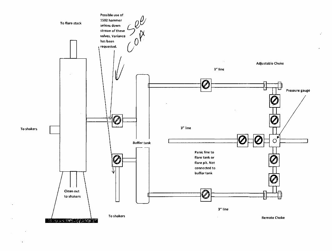
To flare stack
Possible use of
1S02 hammer
unions down
stream of these
valves. Variance
has been
requested.
9 0)
0
To shakers
To shakers
Adjustable Choke
Remote Choke
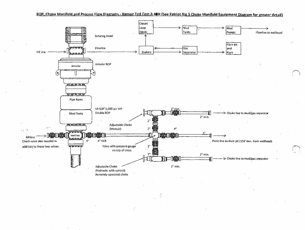
BOP, Choke Manifold and Process Flow Diagrams - Hamon Fed Com A #»H (See Patriot Rig S Choke Manifold Equipment Diagram for greater detain
Fill line
m s StJ : < f A3. If
Closed
Loop
Equip.
Mud
Tanks Rotating Head
Flow line
Shakers
Annular Annular BOP
i^f i f f * rrf\
Pipe Rams
; / 13-5/8" 5,000 psi WP
Blind Rams I D ° u b l e B 0 P
ffft rtfi tfTi Adjustable Choke
(Manual)
Kill line "
Check valve also needed in
addition to these two valves,
wrTgrrr^grmr
4" 4" HCR
Valve wi th pressure gauge
on top of cross
Adjustable Choke
(Hydraulic with control)
Remotely operated choke
Gas
Separator
2" min.
2" min.
2" min.
4"
Mud
Pumps Flowline to wellhead
Flare pit
and
Flare
- > Choke line to mud/gas separator
Panic line to flare pit (150' min. from wellhead)
2" min. - > Choke line to mud/gas separator

c (
5M Choke Manifold Equipment
SUB/RIG
Celiac
SOP
Hydraulic Adjustable Choke with control
/?e^o^// opera tec/ Manual Adjustable
Mansion Chamber
a JO u. o
Please note that the Expansion Chamber Is not connected to he ys^c^/c
To Separator
ifl.niL' W Cft.nnc+ Connexs.-T -to (YMkfaps Seps-r^W. AddHl^^j
Verrt {')&£. "is rteectacL -70/--

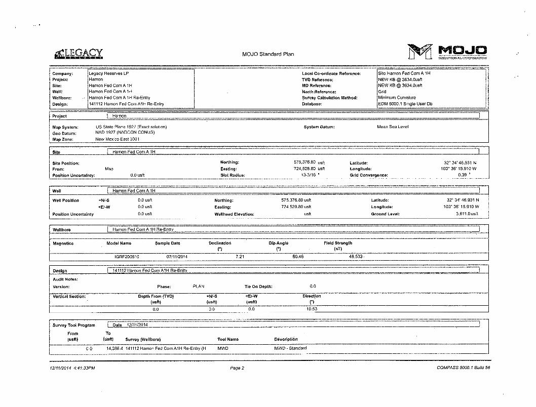
Legacy Reserves LP Hamon Hamon Fed Com A 1H Hamon Fed Com A 1H Re-Entry
Plan: 141112 Hamon Fed Com A1H Re-Entry
MOJO Standard Plan 12 November, 2014
MOJO Standard Plan M O J O
Company:
Project:
Site:
Well:
Wellbore:
Design:
Legacy Reserves LP
Hamon
Hamon Fed Com A 1H
Hamon Fed Com A 1H
Hamon Fed Com A 1H Re-Entry
141112 Hamon Fed Com A1H Re-Entry
Local Co ordinate Reference:
TVD Reference;
MP Reference;
North Reference:
Survey Calculation Method:
Database:
Site Hamon Fed Com A 1H
NEW KB @ 3634.0usfi
NEW KB @ 3634.0usft
Grid
Minimum Curvature
EDM 5000.1 Single User Db
Project | Hamon
Map System:
Geo Datum:
Map Zone:
US State Plane 1927 (Exact solution)
NAD 1927 (NADCON CONUS)
New Mexico East 3001
System Datum: Mean Sea Level
Site I Hamon Fed Com A1H | [
Site Position:
From: Map
Position Uncertainty: 0.0 usft
Northing:
Easting:
Slot Radius:
575,376.80 usft Latitude: 32° 34' 46.931 N
724,528.80 usft Longitude: 103" 36' 15.910 W
13-3/16 " Grid Convergence: 0.39 °
Well I Hamon Fed Com A1H ZZZZZZZ I IZ ] Well Position
Position Uncertainty
+N/-S
+E/-W
0.0 usft
0.0 usft
0.0 usft
Northing:
Easting:
Wellhead Elevation:
575,376.80 usft
724,528.80 usft
usft
Latitude:
Longitude:
Ground Level:
32° 34' 46.931 N
103° 36'15.910 W
3,611.0usft
Wellbore H a m o n F e d C o n ^ ^
Magnetics Model Name Sample Date Declination Dip Angle Field Strength
T) T) - (nT) IGRF200510 07/11/2014 7.21 60.46 48,533-
Design I 141112 Hamon Fod Com A1H Re-Entry
Audit Notes:
Version: Phase: PLAN Tie On Depth: 0.0
Vertical Section: Depth From (TVp) (usft)
+N/-S (usft)
+E/-W (usft)
Direction
o' 0.0 0.0 0.0 10.53
Survey Tool Program I Date 12/11/2014
From (usft)
To (usft) Survey (Wellbore) Tool Name Description
0,0 14,396.4 141112 Hamon Fed Com A1H Re-Entry (H MWD MWD - Standard
12/11/2014 4:41:33PM Page 2 COMPASS 5000.1 Build 56
^LEGACY MOJO Standard Plan M O J O DiFtCTiONAl. COHSP0RAT10S*
Company:
Project:
Site:
Well:
Wellbore:
Design:
Legacy Reserves LP
Hamon
Hamon Fed Com A1H
Hamon Fed Com A 1H
Hamon Fed Com A1H Re-Entry
141112 Hamon Fed Com A1H Re-Entry
Local Co-ordinate Reference:
TVD Reference:
MD Reference:
North Reference:
Survey Calculation Method:
Database:
Site Hamon Fed Com A 1H
NEW KB @ 3634.0usft
NEW KB @ 3634.0usfl
Grid
Minimum Curvature
EDM 5000.1 Single User Db
MP (USft)
Inc
a A4I (azimuth)
O TVD (usft)
TVDSS
(USft)-N/S
(usft) E/W
(USft) V. Sec (usft)
PLeg f / 1 OOusft)
Northing (Usft)
Easting I (usft) !
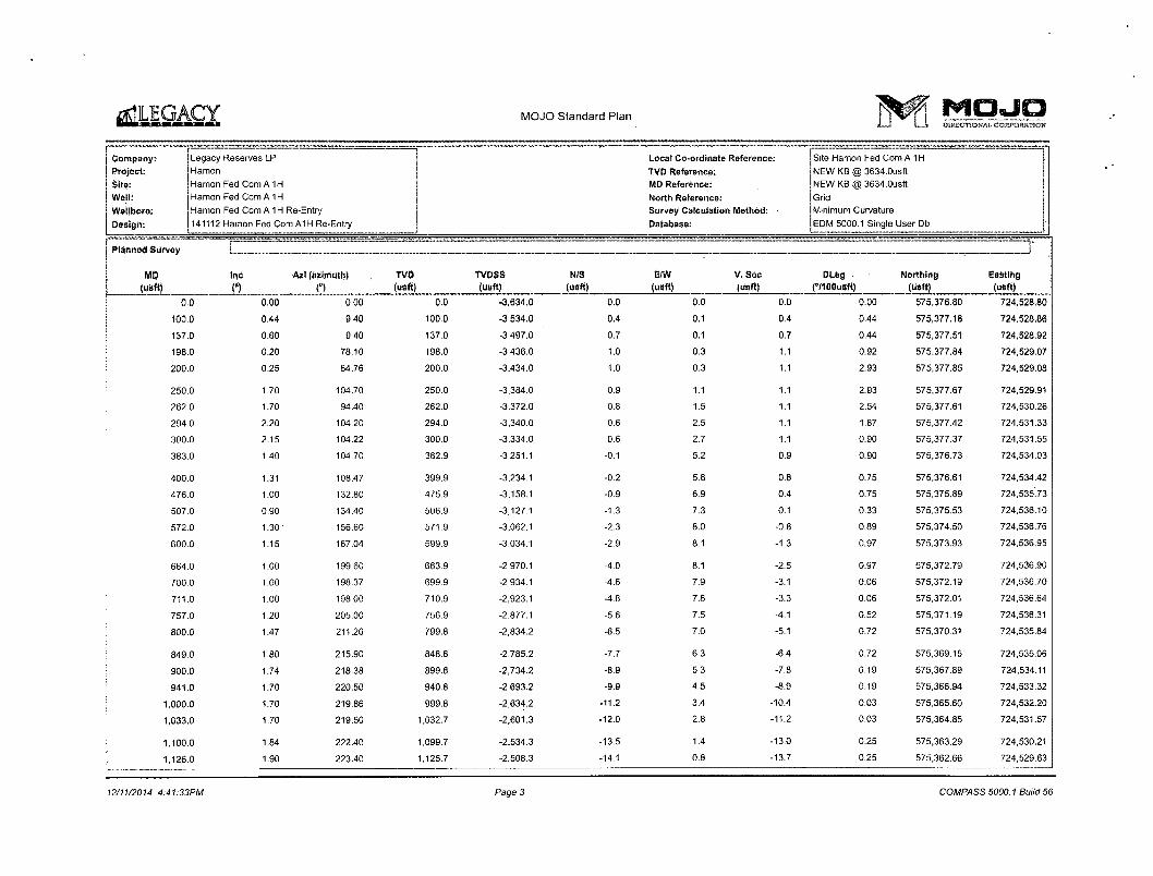
0.0 0,00 0.00 0.0 -3,634.0 0.0 0.0 0.0 0.00 575,376.80 724,528.80
100.0 0,44 9.40 100.0 -3,534.0 0.4 0.1 0.4 0,44 575,377.18 724,528,86
137.0 0.60 9,40 137.0 -3,497.0 0.7 0.1 0.7 0.44 575,377.51 724,528.92
198.0 0.20 78.10 198.0 -3,436.0 1.0 0.3 1.1 0.92 575,377.84 724,529.07
200.0 0.25 84.76 200.0 -3,434.0 1.0 0.3 1.1 2.93 575,377.85 724,529.08
250.0 1.70 104.70 250.0 -3.384.0 0.9 1.1 1.1 2.93 575,377.67 724,529.91
262.0 1.70 94.40 262.0 -3,372.0 0.8 1.5 1.1 2.54 575,377.61 724,530.26
294.0 2.20 104.20 294.0 -3,340.0 0.6 2.5 1.1 1.87 575,377.42 724,531.33
300.0 2.15 104.22 300.0 -3,334.0 0.6 2.7 1.1 0.90 575,377.37 724,531.55
383.0 1.40 104.70 382.9 -3,251.1 -0.1 5.2 0.9 0.90 575,376.73 724,534.03
400.0 1.31 108.47 399.9 -3,234.1 -0.2 5.6 0.8 0.75 575,376.61 724,534.42
476.0 1.00 132.80 475.9 -3,158.1 -0.9 6.9 0.4 0.75 575,375.89 724,535.73
507.0 0.90 134.40 506.9 -3,127.1 -1.3 7.3 0.1 0.33 575,375.53 724,536.10
572.0 1.30 156.60 571.9 -3.062.1 -2.3 8.0 -0.8 0.89 575,374.50 724,536.76
600.0 1.15 167.04 599.9 -3,034.1 -2.9 8.1 -1.3 0.97 575,373.93 724,536.95
664.0 1.00 199.60 663.9 -2,970.1 -4.0 8.1 -2.5 0.97 575,372.79 724,536.90
700.0 1.00 198.37 699.9 -2,934.1 -4.6 7.9 -3.1 0.06 575,372.19 724,536.70
711.0 1.00 198.00 710.9 -2,923.1 -4.8 7.8 -3.3 0.06 575,372.01 724,536.64
757.0 1.20 205.00 756.9 -2,877.1 -5.6 7.5 -4.1 0.52 575,371.19 724,536.31
800.0 1.47 211.20 799.8 -2,834.2 -6.5 7.0 -5.1 0.72 575,370.31 724,535.84
849.0 1.80 215.90 848.8 -2,785.2 -7.7 6.3 -6.4 0.72 575,369.15 724,535.06
900.0 1.74 218.38 899.8 -2,734.2 -8.9 5.3 -7.8 0.19 575,367.89 724,534.11
941.0 1.70 220.50 940.8 -2,693.2 -9.9 4.5 -8.9 0.19 575,366.94 724,533.32
1,000.0 1.70 219.86 999.8 -2,634.2 -11.2 3.4 -10.4 0.03 575,365.60 724,532.20
1,033.0 1.70 219.50 1,032.7 -2,601.3 -12.0 2.8 -11.2 0.03 575,364.85 724,531.57
1,100.0 1.84 222.40 1.099.7 -2.534.3 -13.5 1.4 -13.0 0.25 575,363.29 724,530.21
1.126.0 1.90 223.40 1,125.7 -2,508.3 -14.1 0.8 -13.7 0.25 575,362.66 724,529.63
12/11/2014 4:41:33PM Page 3 COMPASS 5000.1 Build 56

LEGACY MOJO Standard Plan M O J O
Company: Project:
Sites
Well:
Wellbore:
Design:
Legacy Reserves LP
Hamon
Hamon Fed Com A 1H
Hamon Fed Com A1H
Hamon Fed Com A1H Re-Entry
141112 Hamon Fed Com A1H Re-Entry
Local Coordinate Reference:
TVD Reference;
MD Reference:
North Reference:
Survey Calculation Method:
Database:
Site Hamon Fed Com A 1H
NEW KB @ 3634.0usft
NEW KB @ 3634.0usft
Grid
Minimum Curvature
EDM 5000.1 Single User Db
Planned Survey
MD (usft)
CZZZZ Planned Survey
MD (usft)
Inc
n Azi (azimuth)
C) TVD (usft)
TVDSS • (usft)
N/S (usft)
E/W (usft)
V. Sec (usft)
DLeg fVlOOusft)
Northing (usft)
Easting (usft)
1,200.0 1.81 233.28 1,199.7 -2,434.3 -15.7 -0.9 -15.6 0.45 575,361.07 724,527.85
1,218.0 1.80 235.80 1,217.6 -2,416.4 -16.1 -1.4 -16.0 0.45 575,360.74 724,527.39
1,300.0 1.35 229.04 1,299.6 -2,334.4 -17.4 -3.2 -17.7 0.59 575,359.38 724,525.59
1,310.0 1.30 227.90 1,309.6 -2,324.4 -17.6 -3.4 -17.9 0.59 575.359.23 724,525.42
1,402.0 1.60 222.20 1,401.6 -2,232.4 -19.2 -5.0 -19.8 0.36 575.357.58 724,523.78
1,500.0 2.00 218.34 1.499.5 -2,134,5 -21.6 -7.0 -22.5 0.43 575,355.22 724,521.80
1,547,0 2.20 217.00 1,546.5 -2.087.5 -22.9 •8.1 -24.0 0.43 575,353,86 724,520.75
1,587.0 2.23 214.12 1,586.5 -2.047.5 -24.2 •8.9 -25.4 0.29 575,352,60 724.519.85
13 3/8"
1,597.0 2.24 213.41 1,596.5 -2,037.5 -24.5 -9.2 -25.8 0.29 575.352.28 724,519.63
1,600.0 2.24 213.20 1,599.5 -2.034.5 -24.6 •9.2 -25.9 0.29 575,352.18 724.519.57
1,670.0 2.30 208.40 1,669.4 -1,964.6 -27.0 -10.6 -28.5 0.29 575,349.80 724,518.15
1,680.6 2.21 208.02 1,680.0 -1,954.0 -27.4 -10.8 -28.9 0.89 575,349.43 724,517.96
Rustler 1,687.6 2.15 20/ 74 1.68/0 -{,947.6
--27.6 " " "
-_. -11.0 -29.1 0.89 575,349 20 724,517.83
1,700.0 2.04 207.22 1,699.4 -1,934.6 -28.0 -11.2 -29.6 0.89 575,348.80 724,517.62
1,762.0 1.50 203.50 1,761.4 -1,872.6 -29.7 -12.0 -31.4 0.89 575,347.07 724,516.80
1,800.0 1.25 203.21 1,799.3 -1,834.7 -30.6 -12.4 -32.3 0.65 575,346.23 724,516.43
1,855.0 0.90 202.50 1,854.3 -1,779.7 -31.5 -12.8 -33.3 0.65 575,345.28 724,516.03
1,900.0 1.13 212.50 1,899.3 -1,734.7 -32.2 -13.1 -34.1 0.65 575,344.58 724,515.66
1,947.0 1.40 219.20 1,946.3 -1,687.7 -33.1 -13.8 -35.0 0.65 575,343.74 724,515.04
1,960.7 1.23 217.26 1,960.0 -1,674.0 -33.3 -14.0 -35.3 1.25 575,343.50 724,514.85
Top Salt 1.S67.7 ~1.15 216 05 1,967.0 ~" -1,667.0 -33.4 -14.0 -35.4 1.25 575,343.38 724,514.76
2,000.0 0.77 207.14 1,999.3 -1,634.7 -33.9 -14.3 -35.9 1.25 575,342.92 724,514.47
2,039.0 0.40 174.60 2,038.3 -1,595.7 -34.2 -14.4 -36.3 1.25 575,342.55 724,514.36
2,100.0 0.91 143.52 2,099.3 -1,534.7 -34.8 -14.1 -36.8 0.99 575,341.95 724,514.67
12/11/2014 4:41:33PM Page 4 COMPASS 5000.1 Build 56

^LEGACY M O J O S t a n d a r d P l a n M O J O
Company:
project:
Site:
Wall:
Wellbore:
Design:
Planned Survey
Legacy Reserves LP
Hamon
Hamon Fed Com A1H
Hamon Fed Com A1H
Hamon Fed Com A1H Re-Entry
141112 Hamon Fed Com A1H Re-Entry
Local Co-ordinate Reference;
TVD Reference:
MD Reference:
North Reference:
Survey Calculation Method:
Database:
Site Hamon Fed Com A 1H
NEW KB @ 3634.0usft
NEW KB @ 3634.0usft
Grid
Minimum Curvature
EDM 5000.1 Single User Db
MD usft)
Inc
o Azi (azimuth)
0 TVD (usft)
TVDSS (usft)
N/S (usft)
E/W (usft)
V, Sec (usft)
DLeg C/IOOusft)
Northing (usft)
Easting (usft)
2.131.0 1.20 138.50 2,130.3 -1,503.7 -35.3 -13.8 -37.2 0.99 575,341.51 724,515.03
2,200.0 1.26 123.32 2,199.3 -1,434.7 -36.2 -12.7 -37.9 0.48 575,340.55 724,516.15
2,223.0 1.30 118.70 2,222.3 -1.411.7 -36.5 -12.2 -38.1 0.48 575,340.29 724,516.59
2,300.0 1.62 99.58 2,299.2 -1,334.8 -37.1 -10.4 -38.4 0.75 575.339.69 724,518.42
2,316.0 1.70 96.60 2,315.2 -1,318.8 -37.2 -9.9 -38.4 0.75 575.339.62 724,518.88
2,408.0 2.00 85.00 2,407.2 -1,226.8 -37.2 -7.0 -37.8 0.52 575,339.61 724,521.84
2.500.0 2.10 45.30 2,499.1 -1,134.9 -35.9 -4.2 -36.0 1.52 575,340.93 724,524.63
2,593.0 2.30 23.90 2,592.1 -1,041.9 -33.0 -2.2 -32.8 0.90 575,343.84 724,526.60
2,600.0 2.28 24.84 2,599.1 -1,034.9 -32.7 -2.1 -32.5 0.61 575,344.09 724,526.72
2,685.0 2.10 37.50 2,684.0 -950.0 -29.9 -0.4 -29.5 0.61 575,346.86 724,528.38
2,700.0 2.11 35.86 2,699.0 -935.0 -29.5 -0.1 -29.0 0.41 575,347.30 724,528.70
2,777.0 2.20 27.80 2,775.9 -858.1 -27.0 1.4 -26.3 0.41 575,349.76 724,530.23
2,800.0 2.22 27.02 2,798.9 -835.1 -26.3 1.8 -25.5 0.17 575,350.55 724,530.63
2,831.9 2.26 25.98 2,830.8 -803.2 -25.1 2.4 -24.3 0.17 575,351.67 724,531.19
2,869.0 2.30 24.80 2,867.9 -766.1 -23.8 3.0 -22.8 0.17 575,353.00 724,531.82
2,900.0 2.07 23.85 2,898.8 -735.2 -22.7 3.5 • -21.7 0.76 575,354.07 724,532.31
2,962.0 1.60 21.10 2,960.8 -673.2 -20.9 4.3 -19.8 0.76 575,355.90 724,533.07
3,000.0 1.63 26.61 2,998.8 -635.2 -19.9 4.7 -18.7 0.42 575,356.88 724,533.51
3,054.0 1.70 34.00 3,052.8 -581.2 -18.6 5.5 -17.2 0.42 575,358.23 724,534.30
3,100.0 1.55 32.87 3,098.8 -535.2 -17.5 6.2 -16.0 0.33 575,359.32 724,535.02
3,146.0 1.40 31.50 3,144.7 -489.3 -16.5 6.8 -14.9 0.33 575,360.32 724,535.65
3,200.0 1.81 35.72 3,198.7 -435.3 -15.2 7.7 -13.6 0.79 575,361.58 724,536.49
3,238.0 2.10 37.70 3,236.7 -397.3 -14.2 8.5 -12.4 0.79 575,362.62 724,537.27
3,300.0 0.75 110.72 3,298.7 -335.3 -13.4 9.5 -11.5 3.25 575,363.37 724,538.34
3,331.0 1.30 161.30 3,329.7 -304.3 -13.8 9.8 -11.8 3.25 575,362.96 724,538.65
3,401.3 1.06 147.70 3,400.0 -234.0 -15.1 10.5 -13.0 0.52 575,361.66 724,539.25
Bottom Salt
12/11/2014 4:41:33PM Page 5 COMPASS 5000.1 Build 56

^LEGACY MOJO Standard Plan M O J O
Company;
Project:
Site:
Well:
Wellbore:
Design:
Legacy Reserves LP
Hamon
Hamon Fed Com A 1H
Hamon Fed Com A 1H
Hamon Fed Com A 1H Re-Entry
141112 Hamon Fed Com A1H Re-Entry
Local Co-ordinate Reference:
TVD Reference: MD Reference:
North Reference:
Survey Calculation Method:
Database;
Site Hamon Fed Com A 1H
NEW KB @ 3634.0usft
NEW KB @ 3634.0usft
Grid
Minimum Curvature
EDM 5000.1 Single User Db
Planned Survey . ( ZZZD MO
(usft) Inc
o Azi (azimuth) TVD
O (usft) TVPSS (MSft)
N/S (USft)
E/W (usft)
v; Sec (usft)
PLeg («/100usft)
Northing (usft)
Easting
(usft)
3,408.3 1.04 146.02 3,407.0 -227.0 -15.2 10.5 -13.1 0.52 575.361.55 724,539.32
3,423.0 1.00 142.30 3,421.7 -212.3 -15.5 10.7 -13.2 0.52 575,361.34 724,539.47
3,451.3 1.11 136.02 3,450.0 -184.0 -15.9 11.0 -13.6 0.57 575,360.95 724,539.82
Vales ... . .. 3,458.3 1.14 134.66 3,457.0 -177.0 -16.0 11.1 -13.7 0.57 575,360.85 724,539.91
3,500.0 1.33 127.89 3,498.6 -135.4 -16.5 11.8 -14.1 0.57 575,360.26 724,540.59
3,515.0 1.40 125.90 3,513.6 -120.4 -16.8 12.1 -14.3 0.57 575,360.05 724,540.87
3,608.0 1.20 152.60 3,606.6 -27.4 -18.3 13.4 -15.5 0.68 575,358.52 724,542.24
3,651.4 1.66 159.18 3,650.0 16.0 -19.3 13.9 -16.4 1.13 575,357.52 724,542.68
Seven Rlvors/Capltan .. . , . , _ ... . . _ . ... .. .. 3,658 4 1.74 159.91 3,657.0 23.0 -19,5 13,9 -16.6 1.13 575,357.33 724,542.75
3,700 0 2.20 163,20 3,698.6 64.6 -20.8 14.4 -17.8 1.14 575,355.97 724,543,20
3,792 0 1.40 159.90 3,790.5 156.5 -23.6 15.3 -20.4 0.88 575.353.22 724,544.09
3,800 0 1.37 158.90 3,798.5 164.5 -23.8 15.4 -20.5 0.47 575,353.04 724.544.16
3,885 0 1.10 145.30 3,883.5 249.5 -25.4 16.2 -22.0 0.47 575,351.42 724,544.99
3,900 0 0.95 136.47 3,898.5 264.5 -25.6 16.4 -22.2 1.45 575,351.21 724,545.16
3,977 0 0.90 62.00 3,975.5 341.5 -25.8 17.3 -22.2 1.45 575,351.04 724,546.13
4,000 0 1.14 46.15 3,998.5 364.5 -25.5 17.7 -21.9 1.60 575,351.28 724,546.46
4,069 0 2.10 25.60 4,067.5 433.5 -23.9 18.7 -20.1 1.60 575,352.90 724,547.50
4,100 0 1.76 18.96 4,098.4 464.4 -22.9 19.1 -19.1 1.32 575,353.86 724,547.90
4,162 0 1.20 355.10 4,160.4 526.4 -21.4 19.4 -17.5 1.32 575,355.40 724,548.15
4,200 0 1.53 350.03 4,198.4 564.4 -20.5 19.2 -16.6 0.91 575,356.30 724,548.03
4,254 0 2.00 345.70 4,252.4 618.4 -18.9 18.9 -15.1 0.91 575,357.92 724,547.67
4,300 0 1.54 340.57 4,298.4 664.4 -17.5 18.5 -13.8 1.05 575,359.28 724,547.27
4,347 0 1.10 331.00 4,345.4 711.4 -16.5 18.0 -13.0 1.05 575,360.27 724,546.84
4,400 0 1.16 327.12 4,398.3 764^3 -15.6 17.5 -12.2 0.18 575,361.17 724,546.30
4,439 0 1.20 324.50 4,437.3 803.3 -15.0 17.1 -11.6 0.18 575,361.83 724,545.85
12/11/2014 4:41:33PM Page 6 COMPASS 5000.1 Build 56

^LEGACY MOJO Standard Plan fteff MOJO i I I — l DUtSSJHQKAI, CORPORATION
Company:
Project:
Site:
Well:
Wellbore:
Design:
Legacy Reserves LP
Hamon
Hamon Fed Com A1H
Hamon Fed Com A 1H
Hamon Fed Com A1H Re-Entry
141112 Hamon Fed Com A1H Re-Entry
Local Co-ordinate Reference:
TVD Reference:
MD Reference:
North Reference:
Survey Calculation Method:
Database:
Site Hamon Fed Com A 1H
NEW KB @ 3634.0usft
NEW KB @ 3634.0usft
Grid
Minimum Curvature
EDM 5000.1 Single User Db
Planned Survey I I
MD (usft)
Inc
o Azi (azimuth)
o TVD (usft)
TVDSS (usft)
N/S (usft)
E/W
(USft)
V. Sec (usft)
DLeg (•71 OOusft)
Northing (usft)
Easting (usft)
4,500.0 1.60 327.19 4,498.3 864.3 -13.7 16.2 -10.5 0.66 575,363.06 724,545.02
4,531.0 1.80 328.10 4,529.3 895.3 -13.0 15.7 -9.9 0.66 575,363.84 724.544.53
4,600.0 1.49 340.30 4,598.3 964.3 -11.2 14.9 -8.3 0.68 575,365.60 724,543.66
4,621.7 1.40 345.20 4,620.0 986.0 -10.7 14.7 -7.8 0.68 575,366.12 724,543.49
Queen 4,623.0 1.40 345.50 4,621.3 987.3 -10.6 14.7 -7.8 0.68 575,366.15 724.543.48
4,628.7 1.39 345.21 4,627.0 993.0 -10.5 14.6 -7.7 0.26 575,366.29 724,543.45
4.700.0 1.23 341.15 4,698.2 1.064.2 -9.0 14.2 -6.2 0.25 575,367.85 724,542.98
4,716.0 1.20 340.10 4,714.2 1,080.2 -8.6 14.1 -5.9 0.25 575,368.17 724,542.87
4,808.0 1.60 341.20 4,806.2 1,172.2 -6.5 13.3 -4.0 0.44 575,370.29 724,542.13
4,900.0 1.49 341.82 4,898.2 1,264.2 -4.2 12.5 -1.8 0.12 575,372.64 724,541.34
5,000.0 1.37 342.60 4,998.2 1,364.2 -1.8 11.8 0.4 0.12 575,375.02 724,540.58
5,100.0 1.25 343.54 5,098.1 1,464.1 0.4 11.1 2.4 0.12 575.377.20 724,539.91
5,200.0 1.13 344.67 5,198.1 1.564.1 2.4 10.5 4.3 0.12 575,379.19 724,539.34
5,300.0 1.01 346.08 5.298.1 1.664.1 4.2 10.1 6.0 0.12 575,381.00 724,538.87
5,350.0 0.95 346.91 5,348.1 1,714.1 5.0 9.9 6.8 0.12 575,381.83 724,538.67
Set Whipstock at 5350ftMD, Mill window at 78dog Azi -5,400.0 1.11 51.33
9 5/8" 5,398.1 1,764.1 5,7 10.2 "7.5 2.21 575,382.54 724,538.95
5.455.0 2.10 78.00 5,453.1 1.819.1 6.3 11.6 8.3 2.21 575,383.08 724,540.36
Start Nudge to 6Deg@545SftMD 5,500.0 2.46 71.26 5.498.0 1,864.0 6.8 " 13.3 9.V 1.00 575,383.56 724,542.08
5,600.0 3.34 61.82 5,597.9 1,963.9 8.8 17.9 11.9 1.00 575,385.63 724,546.68
5,668.3 3.98 57.85 5,666.0 2,032.0 11.0 21.6 14.8 1.00 575,387.83 724.550.44
Delaware 5,700.0 4.28 56.40 5,697.7 2,063.7 12.3 23.6 16.4 1.00 575.389.07 724,552.36
5,800.0 5.24 > 52.94 5,797.3 2,163.3 17.1 30.3 22.3 1.00 575,393.88 724.559.11
5.878.7 6.00 51.00 5,875.7 2,241.7 21.8 36.4 28.1 1.00 575,398.64 724,565.17
12/11/2014 4:41:33PM Page 7 COMPASS 5000.1 Build 56

MOJO Standard Plan ftepf MOJO *LJ L_l mmxmoHKu CORPORATION
Company:
Project:
Site:
Well:
Wellbore:
Design:
Planned Survey
MD
(usft)
Legacy Reserves LP
Hamon
Hamon Fed Com A 1H
Hamon Fed Com A 1H
Hamon Fed Com A 1H Re-Entry
141112 Hamon Fed ComAIH Re-Entry
Local Co-ordinate Reference:
TVD Reference:
MD Reference:
North Reference:
Survey Calculation Method;
Database:
Site Hamon Fed Com A 1H
NEW KB @ 3634.0usft
NEW KB @ 3634.0usft
Grid
Minimum Curvature
EDM 5000.1 Single UserDb
Inc Azi (azimuth)
o TVD (usft)
TVDSS (usft)
N/S
(usft)
E/W (usft)
V, Sec
(usft)
DLeg
(°/1 OOusft)
Northing
(usft)
Easting
(usft)
5,900.0 6.00 51.00 5,896.8 2,262.8 23.2 38.1 29.8 0.00 575.400.04 724,566.90
6,000.0 6.00 51.00 5,996.3 2,362.3 29.8 46.2 37.8 0.00 575,406.61 724,575.02
6,100.0 6.00 51.00 6,095.7 2,461.7 36.4 54.3 45.7 0.00 575,413.19 724,583.15
6,200.0 6.00 51.00 6,195.2 2,561.2 43.0 62.5 53.7 0.00 575.419.77 724,591.27
6,300.0 6.00 51.00 6,294.6 2,660.6 49.5 70.6 61.6 0.00 575,426.35 724,599.39
6,400.0 6.00 51.00 6,394.1 2,760.1 56.1 78.7 69.6 0.00 575,432.93 724,607.52
6,500.0 6.00 51.00 6,493.5 2,859.5 62.7 86.8 77.5 0.00 575,439.51 724,615.64
6,600.0 6.00 51.00 6,593.0 2,959.0 69.3 95.0 85.5 0.00 575,446.08 724,623.76
6,700.0 6.00 51.00 6,692.4 3,058.4 75.9 103.1 93.4 0.00 575,452.66 724,631.89
6,800.0 6.00 51.00 6,791.9 3,157.9 82.4 111.2 101.4 0.00 575,459.24 724,640.01
6,900.0 6.00 51.00 6,891.3 3,257.3 89.0 119.3 109.3 0.00 575,465.82 724,648.13
7,000.0 6.00 51.00 6.990.8 3,356.8 95.6 127.5 117.3 0.00 575,472.40 724,656.26
7,100.0 6.00 51.00 7,090.3 3,456.3 102.2 135.6 125.2 0.00 575,478.97 724,664.38
7,200.0 6.00 51.00 7,189.7 3.555.7 108.8 143.7 133.2 0.00 575.485.55 724.672.50
7,300.0 6.00 51.00 7,289.2 3,655.2 115.3 151.8 141.1 0.00 575,492.13 724.680.63
7,400.0 6.00 51.00 7,388.6 3,754.6 121.9 160.0 149.1 0.00 575,498.71 724.688.75
7,500.0 6.00 51.00 7,488.1 3,854.1 128.5 168.1 157.0 0.00 575,505.29 724,696.87
7,600.0 6.00 51.00 7,587.5 3.953.5 135.1 176.2 165.0 0.00 575,511.87 724,705.00
7,700.0 6.00 51.00 7,687.0 4,053.0 141.6 184.3 173.0 0.00 575,518.44 724,713.12
7,800.0 6.00 51.00 7,786.4 4,152.4 148.2 192.4 180.9 0.00 575,525.02 724,721.24
7,900.0 6.00 51.00 7,885.9 4,251.9 154.8 200.6 188.9 0.00 575,531.60 724,729.37
8,000.0 6.00 51.00 7,985.3 4,351.3 161.4 208.7 196.8 0.00 575,538.18 724,737.49
8,100.0 6.00 51.00 8,084.8 4,450.8 168.0 216.8 204.8 0.00 575,544.76 724,745.61
8,200.0 6.00 51.00 8,184.2 4,550.2 174.5 224.9 212.7 0.00 575,551.33 724,753.74
8,220.9 6.00 51.00 8.205.0 4,571.0 175.9 226.6 214.4 0.00 575,552.71 724,755.43
Bone Spring
8,300.0 6.00 51.00 8,283.7 4,649.7 181.1 233.1 220.7 0.00 575,557.91 724,761.86
12/11/2014 4:41:33PM Page 8 COMPASS 5000.1 Build 56

^LEGACY MOJO Standard Plan MIOJIO DERECHOWU, CORPORATION
Company:
Project:
Site:
Wall:
Wellbore:
Design:
Planned Survey
M0
Legacy Reserves LP
Hamon
Hamon Fed Com A 1H
Hamon Fed Com A 1H
Hamon Fed Com A 1H Re-Entry
141112 Hamon Fed Com A1H Re-Entry
Local Co-ordinate Reference:
TVD Reference:
MD Reference:
North Reference:
Survey Calculation Method:
Database:
Site Hamon Fed Com A1H
NEW KB @ 3634.0usft
NEW KB @ 3634.0usft
Grid
Minimum Curvature
EDM 5000.1 Single User Db
Inc
C) Azi (azimuth)
O TVD (usft)
TVDSS (usft)
NIS (usft)
E/W (usft)
V.Sec (usft)
DLeg (VlOOusft)
Northing (usft)
Easting (usft)
8,400.0 6.00 51.00 8,383.1 4,749.1 187.7 241.2 228.6 0.00 575,564.49 724,769.98
8,500.0 6.00 51.00 8,482.6 4,848.6 194.3 249.3 236.6 0.00 575,571.07 724,778.11
8,600.0 6.00 51.00 8,582.0 4,948:0 200.8 257.4 244.5 0.00 575,577.65 724,786.23
8,700.0 6.00 51.00 8,681.5 5,047.5 207.4 265.6 252.5 0.00 575,584.23 724,794.35
8,800.0 6.00 51.00 8,780.9 5,146.9 214.0 273.7 260.4 0.00 575,590.80 724,802.48
8,900.0 6.00 51.00 8,880.4 5,246.4 220.6 281.8 268.4 0.00 575,597.38 724,810.60
8,979.1 6.00 51.00 8,959.1 5,325.1 225.8 288.2 274.7 0.00 575,602.59 724,817.03
KOP@8979ftMD _ 9,000.0 8 09 51.00 6 979.8 5545.8 " 227.4 ' 290.2 276 6 " 9.99 575,604.20 724,819.02
9,050.0 13.09 51.00 9,028.9 5,394.9 233.2 297.4 283.6 10.00 575.609.98 724,826.16
9,100.0 18.09 51.00 9,077.1 5,443.1 241.6 307.8 293.8 10.00 575,618.43 724,836.60
9,150.0 23.09 51.00 9,123.9 5,489.9 252.7 321.5 307.2 10.00 575,629.49 724,850.26
9,200.0 28.09 51.00 9,169.0 5,535.0 266.3 338.2 323.6 10.00 575,643.08 724,867.03
9,250.0 33.09 51.00 9,212.0 5,578.0 282.3 358.0 343.0 10.00 575,659.09 724,886.80
9,300.0 38.09 51.00 9,252.6 5,618.6 300.6 380.6 365.1 10.00 575,677.39 724,909.41
9,350.0 43.09 51.00 9,290.6 5,656.6 321.1 405.9 389.8 10.00 575,697.86 724,934.68
9.400.0 48.09 51.00 9,325.6 5,691.6 343.5 433.6 417.0 10.00 575,720.33 724,962.43
9,450.0 53.09 51.00 9,357.3 5,723.3 367.8 463.6 446.4 10.00 575,744.63 724,992.44
9,500.0 58.09 51.00 9,385.5 5,751.5 393.8 495.7 477.8 10.00 575,770.58 725,024.49
9,519.1 60.00 51.00 9,395.4 5,761.4 404.1 508.4 490.2 10.00 575.780.90 725,037.22
9,550.0 62.14 48.46 9,410.3 5,776.3 421.6 529.0 511.2 10.00 575,798.37 725,057.84
9,800.0 65.70 44.54 9,432.3 5.798,3 452.5 561.6 547.5 10.00 575,829.29 725,090,39
9.650.0 69.35 40,85 9,451.4 5,817.4 486.4 592.9 586.6 10.00 575,863.25 725,121,69
9,700,0 73.08 37.32 9,467.5 5,833.5 523.2 622.7 628.2 10.00 575,899.99 725,151.51
0,750.0 76.86 33.94 9,480.5 5,846.5 562.4 650.8 671.9 10.00 575,939.23 725,179,62
9,800.0 80.69 30.66 9,490.2 5,856.2 603.9 677.0 717.5 10.00 575,980.68 725,205.81
9,850.0 84.55 27.45 9,496.7 5,862.7 647.2 701.1 764.5 10.00 576,024.01 725,229.88
12/11/2014 4:41:33PM Page 9 COMPASS 5000.1 Build 56

MOJO Standard Plan ffcfj M O J O
Company:
Project:
Site:
Well:
Wellbore:
Design:
Planned Survey
Legacy Reserves LP
Hamon
Hamon Fed Com A1H
Hamon Fed Com A1H
Hamon Fed Com A1H Re-Entry
141112 Hamon Fed Com A1H Re-Entry
Local Co-ordinate Reference:
TVD Reference:
MD Reference:
North Reference:
Survey Calculation Method:
Database:
Site Hamon Fed Com A 1H
NEW KB @ 3634.0usft
NEW KB @ 3634.0usft
Grid
Minimum Curvature
EDM 5000.1 Single User Db
MD Inc Azi (azimuth) TVD TVDSS HIS E/W V. Sec DLeg Northing Easting (usft) o O (usft) (usft) (usft) (usft) (usft) (°/100usft) (usft) (usft)
9.900.0 88.42 24.28 9,499.7 5,865.7 692.1 722.8 812.6 10.00 576,068.90 725,251.65
9,920.4 90.00 23.00 9,500.0 5,866.0 710.7 731.0 832.4 10.00 576,087.54 725,259.81
10,000.0 90.00 21.41 9,500.0 5,866.0 784.5 761.1 910.4 2.00 576,161.28 725.289.90
10,100.0 90.00 19.41 9,500.0 5,866.0 878.2 796.0 1,008.9 2.00 576,255.00 725,324.77
10,200.0 90.00 17.41 9,500.0 5,866.0 973.1 827.5 1,108.0 2.00 576.349.88 725,356.35
10.300.0 90.00 15.41 9,500.0 5,866.0 1.069.0 855.8 1.207.4 2.00 576,445.80 725,384.59
10,400.0 90.00 13.41 9,500.0 5,866.0 1,165.9 880.7 1,307.2 2.00 576,542.65 725,409.47
10,500.0 90.00 11.41 9,500.0 5,866.0 1,263.5 902.2 1,407.1 2.00 576,640.31 725.430.95
10,600.0 90.00 9.41 9,500.0 5,866.0 1,361.9 920.2 1,507.1 2.00 576,738.66 725,449.02
10,700.0 90.00 7.41 9,500.0 5,866.0 1,460.8 934.8 1,607.1 2.00 576,837.58 725,463.64
10,800.0 90.00 5.41 9,500.0 5,866.0 1,560.2 946.0 1,706.8 2.00 576,936.96 725,474.80
10,869.5 90.00 4.02 9,500.0 5,866.0 1,629.4 951.7 1,775.9 2.00 577.006.22 725,480.50
Land @ 9920ftMD/9500ftTVD 10.900.0 90.00 3.41 9,500.0 5.866.0 1,659.9 953.7 1,806^2 2.00 577,036.65 725,482.48
11,000.0 90.00 1.41 9,500.0 5.866.0 1,759.8 957.9 1,905.2 2.00 577,136.56 725,486.68
11,070.4 90.00 0.00 9.500.0 5,866.0 1,830.1 958.7 1,974.5 2.00 577,206.90 725.487.54
11,100.0 90.00 0.00 9,500.0 5.866.0 1,859.8 958.7 2,003.7 0.00 577,236.55 725,487.54
11,200.0 90.00 0.00 9,500.0 5.866.0 1,959.8 958.7 2,102.0 0.00 577,336.55 725,487.54
11,300.0 90.00 0.00 9,500.0 5,866.0 2,059.8 958.7 2.200.3 0.00 577,436.55 725,487.54
11,400.0 90.00 0.00 9,500.0 5,866.0 2,159.8 958.7 2,298.6 0.00 577,536.55 725,487.54
11,500.0 90.00 0.00 9.500.0 5,866.0 2,259.8 958.7 2,396.9 0.00 577,636.55 725,487.54
11,600.0 90.00 0.00 9,500.0 5,866.0 2,359.8 958.7 2.495.3 0.00 577,736.55 725,487.54
11,700.0 90.00 0.00 9,500.0 5,866.0 2,459.8 958.7 2,593.6 0.00 577,836.55 725,487.54
11,800.0 90.00 0.00 9,500.0 5,866.0 2,559.8 958.7 2,691.9 0.00 577,936.55 725,487.54
11,900.0 90.00 0.00 9,500.0 5,866.0 2,659.8 958.7 2,790.2 0.00 578,036.55 725,487.54
12,000.0 90.00 0.00 9.500.0 5,866.0 2.759.8 958.7 2.888.5 0.00 578,136.55 725,487.54
12.100.0 90.00 0.00 9,500.0 5,866.0 2,859.8 958.7 2.986.8 0.00 578,236.55 725,487,54
12/11/2014 4:41:33PM Page 10 COMPASS 5000.1 Build 56
MOJO Standard Plan IWf MOJO
Company;
Projects
Site:
Well;
Wellbore:
Design:
Legacy Reserves LP
Hamon
Hamon Fed Com A1H
Hamon Fed Com A 1H
Hamon Fed Com A1H Re-Entry
141112 Hamon Fed Com A1H Re-Entry
Local Co-ordinate Reference:
TVD Reference: Mb Reference;
North Reference:
Survey Calculation Method:
Database:
Site Hamon Fed Com A1H
NEW KB @ 3634.0usft
NEW KB @ 3634.0usft
Grid
Minimum Curvature
EDM 5000.1 Single User Db
MD Inc Azi (azimuth) TVD TVDSS HIS E/W V. Sec DLeg Northing Easting j
(usft) n O (USft) (usft) (Usft) (usft) (usft) («/100usft) (usft) (usft)
12,200.0 90.00 0.00 9,500.0 5,866.0 2,959.8 958.7 3,085.1 0,00 578,336.55 725,487.54
12,300.0 90.00 0.00 9,500.0 5,866.0 3,059.8 958.7 3,183.5 0.00 578,436.55 725,487.54
12,400.0 90.00 0.00 9,500.0 5,866.0 3,159.8 958.7 3,281.8 0.00 578,536.55 725,487.54
12,500.0 90.00 0.00 9,500.0 5,866.0 3,259.8 958.7 3,380.1 0.00 578.636.55 725,487.54
12,600.0 90.00 0.00 9,500.0 5,866.0 3,359.8 958.7 3,478.4 0.00 578,736.55 725,487.54
12,700.0 90.00 0.00 9,500.0 5,866.0 3,459.8 958.7 3,576.7 0.00 578,836.55 725,487.54
12,800.0 90.00 0.00 9,500.0 5,866.0 3,559.8 958.7 3,675.0 0.00 578,936.55 725,487.54
12,900.0 90.00 0.00 9,500.0 5,866.0 3,659.8 958.7 3,773.3 0.00 579,036.55 725,487.54
13,000.0 90.00 0.00 9,500.0 5.866.0 3,759.8 958.7 3,871.7 0.00 579,136.55 725,487.54
13,100.0 90.00 0.00 9,500.0 5,866.0 3,859.8 958.7 3,970.0 0.00 579,236.55 725,487.54
13,200.0 90.00 0.00 9,500.0 5,866.0 3,959.8 958.7 4,068.3 0.00 579,336.55 725,487.54
13,300.0 90.00 0.00 9,500.0 5,866.0 4,059.8 958.7 4,166.6 0.00 579,436.55 725,487.54
13,400.0 90.00 0.00 9,500.0 5,866.0 4,159.8 958.7 4,264.9 0.00 579,536.55 725,487.54
13,500.0 90.00 0.00 9,500.0 5,866.0 4,259.8 958.7 4,363.2 0.00 579,636.55 725,487.54
13,600.0 90.00 0.00 9,500.0 5,866.0 4,359.8 958.7 4,461.6 0.00 579,736.55 725,487.54
13,700.0 90.00 0.00 9,500.0 5,866.0 4,459.8 958.7 4,559.9 0.00 579,836.55 725,487.54
13,800.0 90.00 0.00 9,500.0 5,866.0 4,559.8 958.7 4,658.2 0.00 579,936.55 725,487.54
13,900.0 90.00 0.00 9,500.0 5,866.0 4,659.8 958.7 4,756.5 0.00 580,036.55 725,487.54
14,000.0 90.00 0.00 9,500.0 5,866.0 4,759.8 958.7 4,854.8 0.00 580.136.55 725,487.54
14,100.0 90.00 0.00 9,500.0 5,866.0 4,859.8 958.7 4,953.1 0.00 580,236.55 725,487.54
14,200.0 90.00 0.00 9,500.0 5,866.0 4,959.8 958.7 5,051.4 0.00 580,336.55 725,487.54
14,300.0 90.00 0.00 9,500.0 5,866.0 5,059.8 958,7 5,149.8 0.00 580,436.55 725,487.54
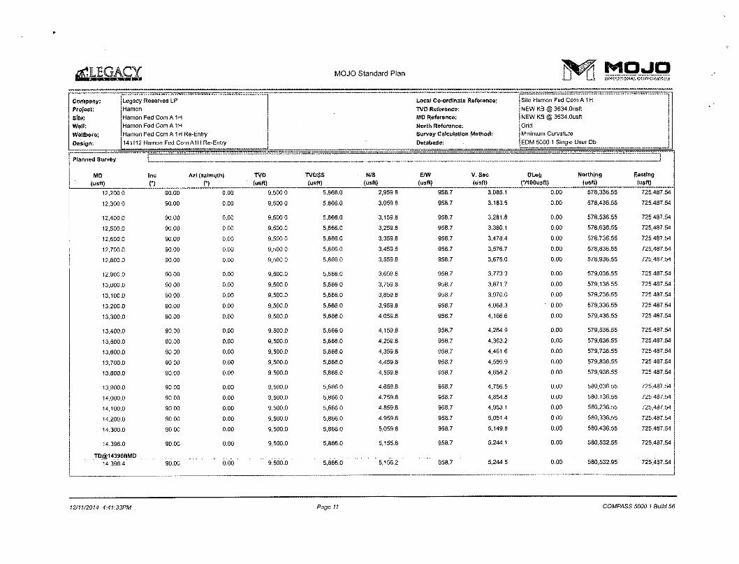
14,396.0 90.00 0.00 9,500.0 5,866,0 5,155.8 958.7 5,244.1 0.00 580,532.55 725,487.54
TD@14396ftMD 14,396.4 90.00 o.do 9.500.0 " 5.866.0 5,156.2 958.7 5.244 5 0.00 580,532.95" 725.487.54
12/11/2014 4:41:33PM Page 11 COMPASS 5000.1 Build 56

MOJO Standard Plan M O J O i _ J LJ» DIRECT! AI* COHPOaflTION
Company: Legacy Reserves LP Local Co-ordinate Reference: Site Hamon Fed Com A 1H
Project: Hamon TVD Reference: NEW KB @ 3634.0usft
Site: Hamon Fed Com A1H MD Reference: NEW KB @ 3634.0usft
Well: Hamon Fed Com A1H North Reference: Grid Wellbore: Hamon Fed Com A 1H Re-Entry Survey Calculation Method: Minimum Curvature
Design: 141112 Hamon Fed Com A1H Re-Entry Database EDM 5000.1 Singla User Db
Casing Points I I Casing Points
Measured Vertical Casing Hole Depth Depth Diameter Diameter (usft) (usft) Name ("! (")
5,350.0 5,348.1 9 5/8" 9-5/8 12-1/4
1,587.0 1,586.5 13 3/8" 13-3/8 16
Formations I !
Measured Vertical Depth Depth Dip (usft) (usft) Name f l
5,668.3 5,666.0 Delaware 0.00
8,220.9 8,205.0 Bone Spring 0.00
1,680.6 1,680.0 Rustler 0.00
3,651.4 3,650.0 Seven Rivers/Capitan 0.00
3,401.3 3,400.0 Bottom Salt 0.00
3,451.3 3,450.0 Yates 0.00
1,960.7 1,960.0 Top Salt 0.00
4,621.7 4,620.0 Queen 0.00
Plan Annotations | |
Measured Vertical Local Coordinates Depth Depth +N/-S +E/-W (usft) (usft) (usft) (usft) Comment
5,350.0 5.348.1 5.0 9.9 Set Whipstock at 5350ftMD, Mill window at 78deg Azi
5,455.0 5,453.1 6.3 11.6 Start Nudge to 6Deg@5455ftMD
8,979.1 8.959.1 225.8 288.2 KOP@ 8979fiMD
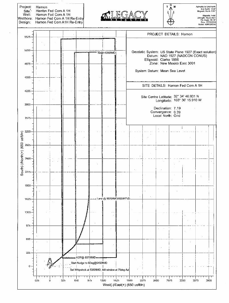
10,869.5 9,500.0 1,629.4 951.7 Land @ 9920ftMD/9500ftTVD
14,396.0 9.500.0 5,155.8 958.7 TD@14396ftMD
Checked By: Approved By: Date:
12/11/2014 4:41:33PM Page 12 COMPASS 5000.1 Build 56
Project: Hamon Site:- Ham'on Fed Com A 1H Well: Hamon Fed Com A 1H
Wellbore: Hamon Fed Com A 1H Re-Entry Design: Hamon Fed ComAIH Re-Entry
*LEGA< R E . S F, R V E 5
Azimuths to Grid North True North: -0.39°
Magnetic North: 6.81°
Magnetic Field Strength: 48533.4snT
Dip Angle: 60.46° Date: 07/11/2014
Model: IGRF200510
PROJECT DETAILS: Hamon
Geodetic System: US State Plane 1927 (Exact solution) Datum: NAD 1927 (NADCON CONUS)
Ellipsoid: Clarke 1866 Zone: New Mexico East 3001
System Datum: Mean Sea Level
SITE DETAILS: Hamon Fed Com A 1H
Site Centre Latitude: Longitude:
32° 34' 46.931 N 103° 36' 15.910 W
Declination: 7.19 Convergence: 0.39
Local North: Grid
^nd @ 9920ftMD/9500ffTVD-
I I I | I I I I | I I I I | I I I I | I I I I | I I I I | I I I I | I I
325 650 975 1300 1625 1950 2275 2600 2925 3250 3575 3900 West(-)/East(+) (650 usft/in)
Project: Hamon Site: ' Harnon Fed Com A 1H Well: Hamon Fed Com A 1H
Wellbore: Hamon Fed Com A 1H Re-Entry Design: Hamon Fed Com A1H Re-Entry
[LEGACY Azimuths to Grid North
True North: -0.39° Magnetic North: 6.81°
Magnetic Field Strength: 48533.4snT
Dip Angle: 60.46' Date: 07/11/2014
Model: IGRF200510
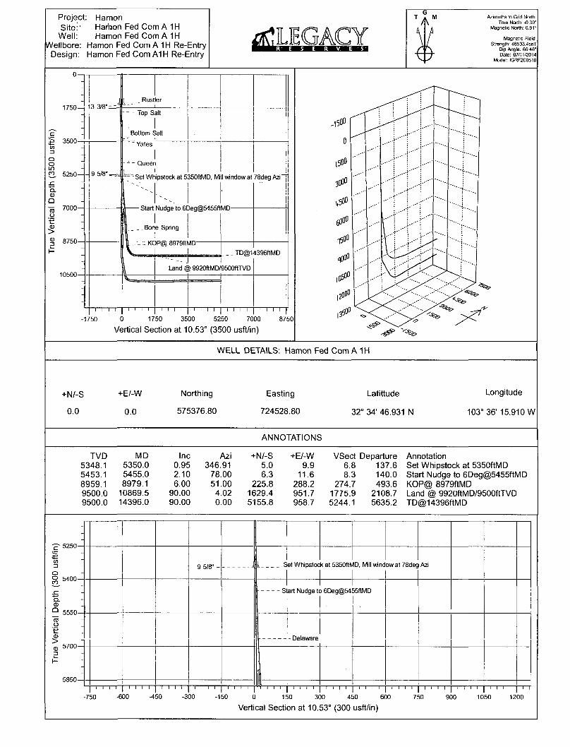
WELL DETAILS: Hamon Fed Com A 1H
+N/-S
0.0
+E/-W
0.0
Northing
575376.80
Easting
724528.80
Latittude
32° 34' 46.931 N
Longitude
103° 36' 15.910 W
ANNOTATIONS
TVD MD Inc Azi +N/-S +E/-W VSect Departure Annotation 5348.1 5350.0 0.95 346.91 5.0 9.9 6.8 137.6 Set Whipstock at 5350ftMD 5453.1 5455.0 2.10 78.00 6.3 11.6 8.3 140.0 Start Nudge to 6Deg@5455ftMD 8959.1 8979.1 6.00 51.00 225.8 288.2 274.7 493.6 KOP@ 8979ftMD 9500.0 10869.5 90.00 4.02 1629.4 951.7 1775.9 2108.7 Land @ 9920ftMD/9500ftTVD 9500.0 14396.0 90.00 0.00 5155.8 958.7 5244.1 5635.2 TD@14396ftMD
- 9 5/8" - J [ -S et Whipstoc k at 5350ftN 1D, Mill wine ow at 78deg Azi
s art Nudge t 3 6Deg@54 55ftMD
- Delaware
I I I I l l l l l l l l l l l l l l l l " I I I I I I I l l l l l l l l l l l l l l l l l l l l I I I I I I
-p 5250-
o o co 5400-
Q. <D Q
O
•e
3
5550-
5700-
5850-
-750 -600 -450 -300 -150 0 150 300 450 600
Vertical Section at 10.53° (300 usft/in) 750 900 1050 1200

CONDITIONS OF APPROVAL
OPERATOR'S NAME: Legacy Reserves Operating, L.P. LEASE NO.: NMNM-84651
WELL NAME & NO.: Hamon Fed Com A 1H SURFACE HOLE FOOTAGE: 0200' FNL & 1010' FWL
BOTTOM HOLE FOOTAGE 0330' FNL & 1980' FWL Sec. 07, T. 20 S., R 34 E., LOCATION: Section 18, T. 20 S., R 34 E., NMPM
COUNTY: Lea County, New Mexico
A. DRILLING OPERATIONS REQUIREMENTS
A BOP/BOPE test shall be conducted prior to drilling out the temporary abandonment plug with-in the_9-5/8 inch intermediate casing.
The BLM is to be notified in advance for a representative to witness:
a. Spudding well (minimum of 24 hours) b. Setting and/or Cementing of all casing strings (minimum of 4 hours) c. BOPE tests (minimum of 4 hours)
3 Lea County Call the Hobbs Field Station, 414 West Taylor, Hobbs NM 88240, (575)393-3612
Hydrogen Sulfide (H2S) monitors shall be installed prior to drilling out the surface shoe and a Hydrogen Sulfide (H2S) Drilling Plan shall be activated 500 feet prior to drilling into the Yates formation. As a result, the Hydrogen Sulfide area must meet Onshore Order 6 requirements, which includes equipment and personnel/public protection items.
Unless the production casing has been run and cemented or the well has been properly plugged, the drilling rig shall not be removed from over the hole without prior approval. If the drilling rig is removed without approval - an Incident of Non-Compliance will be written and will be a "Major" violation.
3. Floor controls are required for 3M or Greater systems. These controls will be on the rig floor, unobstructed, readily accessible to the driller and will be operational at all times during drilling and/or completion activities. Rig floor is defined as the area immediately around the rotary table; the area immediately above the substructure on which the draw works is located, this does not include the dog house or stairway area.
4. The record of the drilling rate along with the GR/N well log run from TD to surface (horizontal well - vertical portion of hole) shall be submitted to the BLM office as well as all other logs run on the borehole 30 days from completion. If available, a digital copy of the logs is to be submitted in addition to the paper copies. The Rustler top and top and bottom of Salt are to be recorded on the Completion Report.
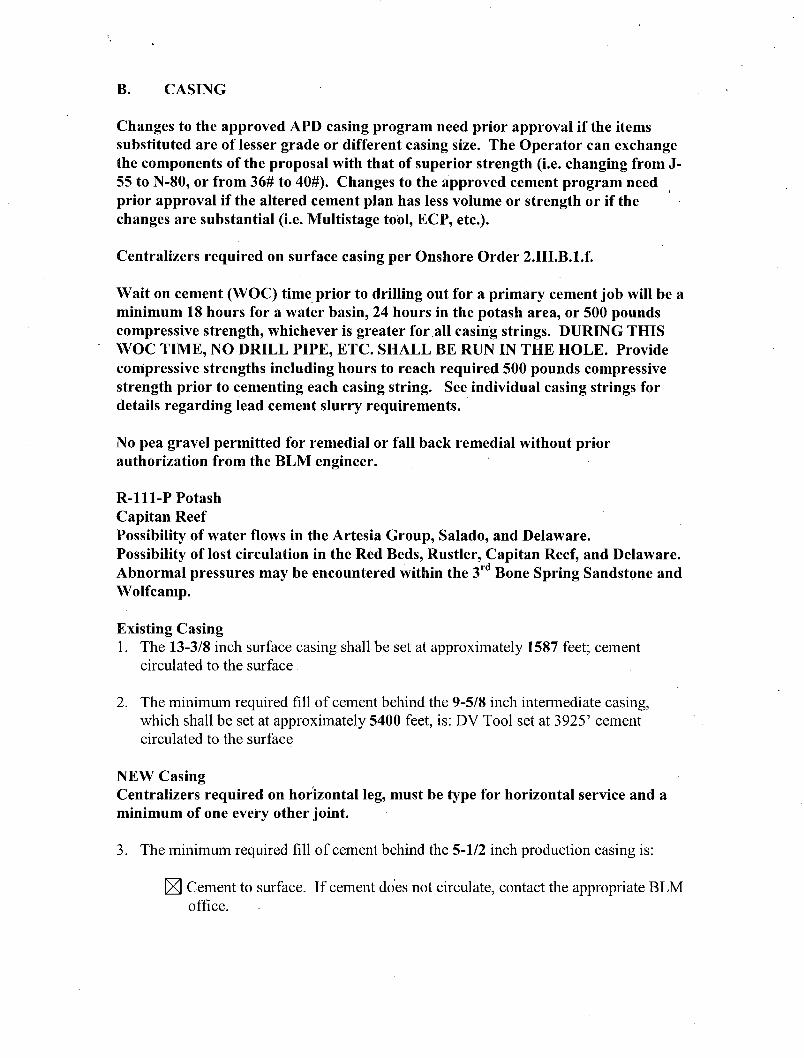
B. CASING
Changes to the approved APD casing program need prior approval if the items substituted are of lesser grade or different casing size. The Operator can exchange the components of the proposal with that of superior strength (i.e. changing from J-55 to N-80, or from 36# to 40#). Changes to the approved cement program need prior approval if the altered cement plan has less volume or strength or if the changes are substantial (i.e. Multistage tool, ECP, etc.).
Centralizers required on surface casing per Onshore Order 2.III.B.l.f.
Wait on cement (WOC) time prior to drilling out for a primary cement job will be a minimum 18 hours for a water basin, 24 hours in the potash area, or 500 pounds compressive strength, whichever is greater for all casing strings. DURING THIS WOC TIME, NO DRILL PIPE, ETC. SHALL BE RUN IN THE HOLE. Provide compressive strengths including hours to reach required 500 pounds compressive strength prior to cementing each casing string. See individual casing strings for details regarding lead cement slurry requirements.
No pea gravel permitted for remedial or fall back remedial without prior authorization from the BLM engineer.
R-l l l -P Potash Capitan Reef Possibility of water flows in the Artesia Group, Salado, and Delaware. Possibility of lost circulation in the Red Beds, Rustler, Capitan Reef, and Delaware. Abnormal pressures may be encountered within the 3 r d Bone Spring Sandstone and Wolfcamp.
Existing Casing 1. The 13-3/8 inch surface casing shall be set at approximately 1587 feet; cement
circulated to the surface
2. The minimum required fill of cement behind the 9-5/8 inch intermediate casing, which shall be set at approximately 5400 feet, is: DV Tool set at 3925' cement circulated to the surface
NEW Casing Centralizers required on horizontal leg, must be type for horizontal service and a minimum of one every other joint.
3. The minimum required fil l of cement behind the 5-1/2 inch production casing is:
Cement to surface. If cement does not circulate, contact the appropriate BLM office.

4. • If hardband drill pipe is rotated inside casing, returns will be monitored for metal. If metal is found in samples, drill pipe will be pulled and rubber protectors which have a larger diameter than the tool joints of the drill pipe will be installed prior to continuing drilling operations.
5. Whenever a casing string is cemented in the R-l 11-P potash area, the NMOCD requirements shall be followed.
C. PRESSURE CONTROL
A BOP/BOPE test shall be conducted prior to drilling out the temporary abandonment plug with-in the_9-5/8 inch intermediate casing.
1. All blowout preventer (BOP) and related equipment (BOPE) shall comply with well control requirements as described in Onshore Oil and Gas Order No. 2 and API RP 53 Sec. 17.
2. Variance approved for operator to use 1502 (15,000 psi) hammer unions downstream of the choke manifold to connect to the mud/gas separator. These hammer unions must be no higher than 3-4 feet above ground level and the stamped 1502 must be visible for the inspector to check. No substitutions for the 1502 will be approved. Operator may be required to show manufacturer data for the 1502.
3. Variance approved to use flex line from BOP to choke manifold. Check condition of flexible line from BOP to choke manifold, replace if exterior is damaged or if line fails test. Line to be as straight as possible with no hard bends and is to be anchored according to Manufacturer's requirements. The flexible hose can be exchanged with a hose of equal size and equal or greater pressure rating. Anchor requirements, specification sheet and hydrostatic pressure test certification matching the hose in service, to be onsite for review. These documents shall be posted in the company man's trailer and on the rig floor. If the BLM inspector questions the straightness of the hose, a BLM engineer will be contacted and will review in the field or via picture supplied by inspector to determine if changes are required (operator shall expect delays if this occurs).
4. Minimum working pressure of the blowout preventer (BOP) and related equipment (BOPE) required for drilling below the 9-5/8 inch intermediate casing shoe shall be 5000 (5M) psi. 5M system requires an HCR valve, remote kill line and annular to match. The remote kill line is to be installed prior to testing the system and tested to stack pressure.
5. The appropriate BLM office shall be notified a minimum of 4 hours in advance for a representative to witness the tests.
a. In potash areas, for all casing strings utilizing slips, these are to be set as soon as the crew and rig are ready and any fallback cement remediation has been done. For all casing strings, casing cut-off and BOP installation can be initiated at twelve hours after bumping the plug. However, no tests shall commence until the cement has had a minimum of 24 hours setup time.
b. The tests shall be done by an independent service company utilizing a test plug not a cup or J-packer.
c. The test shall be run on a 5000 psi chart for a 2-3M BOP/BOP, on a 10000 psi chart for a 5M BOP/BOPE and on a 15000 psi chart for a 10M BOP/BOPE. If a linear chart is used, it shall be a one hour chart. A circular chart shall have a maximum 2 hour clock.
d. The results of the test shall be reported to the appropriate BLM office.
e. All tests are required to be recorded on a calibrated test chart. A copy of the BOP/BOPE test chart and a copy of independent service company test will be submitted to the appropriate BLM office.
f. The BOP/BOPE test shall include a low pressure test from 250 to 300 psi. The test will be held for a minimum of 10 minutes i f test is done with a test plug and 30 minutes without a test plug. This test shall be performed prior to the test at full stack pressure.
D. DRILL STEM TEST
If drill stem tests are performed, Onshore Order 2.III.D shall be followed.
E. WASTE MATERIAL AND FLUIDS
All waste (i.e. drilling fluids, trash, salts, chemicals, sewage, gray water, etc.) created as a result of drilling operations and completion operations shall be safely contained and disposed of properly at a waste disposal facility. No waste material or fluid shall be disposed of on the well location or surrounding area.
Porto-johns and trash containers will be on-location during fracturing operations or any other crew-intensive operations.
EGF 112014