debris mitigation methods for bridge piers · debris mitigation methods for bridge piers june 2012...
TRANSCRIPT

Debris Mitigation Methods for Bridge Piers
Final ReportJune 2012
Sponsored byFederal Highway AdministrationIowa Department of Transportation(InTrans Project 11-395)
About the BEC
The mission of the Bridge Engineering Center is to conduct research on bridge technologies to help bridge designers/owners design, build, and maintain long-lasting bridges.
Disclaimer Notice
The contents of this report reflect the views of the authors, who are responsible for the facts and the accuracy of the information presented herein. The opinions, findings and conclusions expressed in this publication are those of the authors and not necessarily those of the sponsors.
The sponsors assume no liability for the contents or use of the information contained in this document. This report does not constitute a standard, specification, or regulation.
The sponsors do not endorse products or manufacturers. Trademarks or manufacturers’ names appear in this report only because they are considered essential to the objective of the document.
Non-Discrimination Statement
Iowa State University does not discriminate on the basis of race, color, age, religion, national origin, sexual orientation, gender identity, sex, marital status, disability, or status as a U.S. veteran. Inquiries can be directed to the Director of Equal Opportunity and Diversity, (515) 294-7612.
Iowa Department of Transportation Statements
Federal and state laws prohibit employment and/or public accommodation discrimination on the basis of age, color, creed, disability, gender identity, national origin, pregnancy, race, religion, sex, sexual orientation or veteran’s status. If you believe you have been discriminated against, please contact the Iowa Civil Rights Commission at 800-457-4416 or Iowa Department of Transportation’s affirmative action officer. If you need accommodations because of a disability to access the Iowa Department of Transportation’s services, contact the agency’s affirmative action officer at 800-262-0003.
The preparation of this document was financed in part through funds provided by the Iowa Department of Transportation through its “Agreement for the Management of Research Conducted by Iowa State University for the Iowa Department of Transportation” and its amendments.
The opinions, findings, and conclusions expressed in this publication are those of the authors and not necessarily those of the Iowa Department of Transportation.

Technical Report Documentation Page
1. Report No. 2. Government Accession No. 3. Recipient’s Catalog No.
InTrans Project 11-395
4. Title and Subtitle 5. Report Date
Debris Mitigation Methods for Bridge Piers June 2012
6. Performing Organization Code
7. Author(s) 8. Performing Organization Report No.
Terry J. Wipf, Brent M. Phares, and Justin M. Dahlberg InTrans Project 11-395
9. Performing Organization Name and Address 10. Work Unit No. (TRAIS)
Bridge Engineering Center
Iowa State University
2711 South Loop Drive, Suite 4700
Ames, IA 50010-8664
11. Contract or Grant No.
12. Sponsoring Organization Name and Address 13. Type of Report and Period Covered
Iowa Department of Transportation
800 Lincoln Way
Ames, IA 50010
Federal Highway Administration
U.S. Department of Transportation
400 7th Street SW
Washington, DC 20590
Final Report
14. Sponsoring Agency Code
SPR 90-00-RB03-011
15. Supplementary Notes
Visit www.intrans.iastate.edu for color pdfs of this and other research reports.
16. Abstract
Debris accumulation on bridge piers is an on-going national problem that can obstruct the waterway openings at bridges and result in
significant erosion of stream banks and scour at abutments and piers. In some cases, the accumulation of debris can adversely affect the
operation of the waterway opening or cause failure of the structure. In addition, removal of debris accumulation is difficult, time
consuming, and expensive for maintenance programs.
This research involves a literature search of publications, products, and pier design recommendations that provide a cost effective
method to mitigate debris accumulation at bridges. In addition, a nationwide survey was conducted to determine the state-of-the-practice
and the results are presented within.
17. Key Words 18. Distribution Statement
bridge piers—channels—debris mitigation—deflection—rivers—streams No restrictions.
19. Security Classification (of this
report)
20. Security Classification (of this
page)
21. No. of Pages 22. Price
Unclassified. Unclassified. 39 NA
Form DOT F 1700.7 (8-72) Reproduction of completed page authorized


DEBRIS MITIGATION METHODS
FOR BRIDGE PIERS
Final Report
June 2012
Principal Investigator
Terry Wipf
Interim Department Chair/Professor
Department of Civil Engineering, Iowa State University
Co-Principal Investigator
Brent Phares
Director
Bridge Engineering Center
Institute for Transportation, Iowa State University
Authors
Terry Wipf, Brent Phares, Justin Dahlberg
Sponsored by
the Iowa Department of Transportation
and the Federal Highway Administration
State Planning and Research Funding
(SPR 90-00-RB03-011)
Preparation of this report was financed in part
through funds provided by the Iowa Department of Transportation
through its research management agreement with the
Institute for Transportation
(InTrans Project 11-395)
A report from
Institute for Transportation
Iowa State University
2711 South Loop Drive, Suite 4700
Ames, IA 50010-8664
Phone: 515-294-8103 Fax: 515-294-0467
www.intrans.iastate.edu


v
TABLE OF CONTENTS
ACKNOWLEDGMENTS ............................................................................................................ vii
EXECUTIVE SUMMARY ........................................................................................................... ix
INTRODUCTION ...........................................................................................................................1
LITERATURE REVIEW ................................................................................................................2
Debris Types ........................................................................................................................2 Debris Sources .....................................................................................................................2 Debris Transport ..................................................................................................................3 Debris Accumulation ...........................................................................................................3
Methods of Mitigation .........................................................................................................4
Debris Mitigation Method Selection ..................................................................................18
NATIONAL SURVEY ..................................................................................................................22
Survey Questions and Answers .........................................................................................22 Survey Observations ..........................................................................................................26
CONCLUSION ..............................................................................................................................28
REFERENCES ..............................................................................................................................29

vi
LIST OF FIGURES
Figure 1. Debris fins upstream of bridge piers (Lagasse et al. 2010) ..............................................4 Figure 2. Debris fin upstream of bridge pier (Bradley et al. 2005) .................................................5 Figure 3. Debris fins independent of bridge pier structure (Bradley et al. 2005) ............................5
Figure 4. Treibholzfange debris detention device (Wallerstein and Thorne 1997) .........................6 Figure 5. Debris basin constructed from metal. (Bradley et al. 2005) .............................................6 Figure 6. Debris basin constructed from gabions (Bradley et al. 2005) ..........................................7 Figure 7. Debris basin constructed of precast concrete sections (Bradley et al. 2005) ...................7 Figure 8. Weirs on outer bank of river (Bradley et al. 2005) ...........................................................8
Figure 9. Iowa Vanes on outer river bank (Iowa DNR 2006) .........................................................8 Figure 10. Kellner jacks used to redirect flow patterns (Bradley et al. 2005) .................................9 Figure 11. Debris deflector looking upstream (Bradley et al. 2005) .............................................10
Figure 12. Debris deflector schematic (Bradley et al. 2005) .........................................................10 Figure 13. Single column debris deflectors (Lyn et al. 2003) .......................................................11 Figure 14. Debris accumulation at single column debris deflectors (Lyn et al. 2003) ..................12
Figure 15. Plan view of hydrofoil deflector (Oppenheimer and Saunders 1995) ..........................12 Figure 16. Profile view of hydrofoil deflector (Oppenheimer and Saunders 1995) ......................13
Figure 17. Debris sweeper (Bradley et al. 2005) ...........................................................................14 Figure 18. Debris boom protecting surface turbine (Tyler 2011) ..................................................15 Figure 19. Debris rack installed upstream (Bradley et al. 2005) ...................................................16
Figure 20. Steel debris rack (Bradley et al. 2005) .........................................................................16 Figure 21. Timber debris rack (Bradley et al. 2005) ......................................................................17
LIST OF TABLES
Table 1. Debris scenarios seen at bridge sites ..................................................................................2 Table 2. Debris-control countermeasures matrix adapted from Bradley et al. 2005 .....................19 Table 3. Debris mitigation options and review adapted from Sheeder and Johnson 2008 ............20
Table 4. Survey results summary ...................................................................................................26

vii
ACKNOWLEDGMENTS
The authors would like to thank the Office of Bridges and Structures at the Iowa Department of
Transportation (DOT) for sponsoring this research and the Federal Highway Administration for
state planning and research (SPR) funds used for this project. Special thanks are given to Ahmad
Abu-Hawash and Dave Clayman with the Iowa DOT Office of Bridges and Structures.


ix
EXECUTIVE SUMMARY
Debris accumulation on bridge piers is an on-going national problem that can obstruct the
waterway openings at bridges and result in significant erosion of stream banks and scour at
abutments and piers. In some cases, the accumulation of debris can adversely affect the operation
of the waterway opening or cause failure of the structure. In addition, removal of debris
accumulation is difficult, time consuming, and expensive for maintenance programs.
This research involves a literature search of publications, products, and pier design
recommendations that provide methods to mitigate debris accumulation at bridges. In addition, a
nationwide survey was conducted to determine the state-of-the-practice and the results are
presented within.
Numerous methods have been used nationwide with varying degrees of success; even so, no
apparent “best” option exists. Site-specific information (e.g., debris sources, classification, and
transport), along with the balance of many factors (e.g., cost, aesthetics, and environmental
impact) will best direct the method of mitigation used.


1
INTRODUCTION
Debris accumulation on bridge piers is an on-going national problem that can obstruct the
waterway openings at bridges and result in significant erosion of stream banks and scour at
abutments and piers. In some cases, the accumulation of debris can adversely affect the operation
of the waterway opening or cause failure of the structure. In addition, removal of debris
accumulation is difficult, time consuming, and expensive for maintenance programs.
Only limited research has been conducted to determine the best method(s) for debris mitigation.
Several methods have been employed; yet objective comparisons of multiple methods have
rarely been completed.
The objective to this phase of the study was to determine the current state-of-the-practice for
debris mitigation by performing a literature review and national survey of state departments of
transportation (DOTs) and to make comparisons of performance and cost effectiveness of
employed methods. Lastly, tools to assist decisions regarding future implementation by the Iowa
DOT will be offered.
2
LITERATURE REVIEW
A number of researchers and practitioners have made efforts to address the mitigation of debris
accumulation at bridge structures through circulated papers and implemented methods around
the US. As such, it can be argued that certain methods are most effective when used in specific
locations and debris flow scenarios. Even so, it’s quite possible that the recommended mitigation
technique was subjectively selected, rather than selected based on the collection of research and
previously implemented methods.
The following discussion first aims to give a brief overview of debris types, sources, transport
methods, and accumulation tendencies. The reader is referred to the many resources referenced
in these sections for a more extensive discussion of these items. Secondly, debris mitigation
techniques and the characteristics of each method are presented to provide direction for where
each may be most useful and cost effective.
Debris Types
The effects of debris flow must be uniquely evaluated for each structure built over rivers and
streams. Types of debris vary from site to site and should be considered when developing a
mitigation technique or in future construction. Bradley et al. (2005) classify debris scenarios that
are commonly seen at bridge sites and these classifications are listed and briefly defined in Table
1.
Table 1. Debris scenarios seen at bridge sites
Debris Classification Typical Debris Examples
Very Small Buoyant
Debris or No Debris
N/A
Small Floating Debris Small limbs or sticks, prunings, leaves, and refuse
Medium Floating Debris Tree limbs or large sticks
Large Floating Debris Logs or trees
Fine Detritus Fine detritus consists of silt, sand, and fine gravel
Coarse Detritus Coarse gravel or rock
Boulders Large rock
Flowing Debris Varied mass of clay, silt, sand, gravel, rock, refuse, trees, and/or branches
Ice Debris Accumulation of ice in waterway
Debris Sources
Similar to the types of debris, the sources of debris can widely vary. The types listed in Table 1
can be attributed to more than one source including, but not limited to, bank erosion, landmass
failures, wind action, biological decay and old age, loss of foliage at changing seasons,
windthrow, ice loading, animal activities, and riparian zone erosion.
Even though debris can come from a number of sources, problems are most common on rivers
and streams with active bank erosion and those that drain wooded or forested areas or corridors
(Lagasse et al. 2010). A majority of debris usually enters the river during the first big flood of the

3
season and it can be expected that debris problems will be worse when there are long periods
between floods (Chang and Shen 1979). Additionally, streams exhibiting distinct meanders have
been known to have higher rates of debris supply because of the migration commonly seen.
Floating debris is composed mostly of old plants and trees that have been scattered along the
banks of a stream channel and on channel bars for, sometimes, 10 or more years.
Debris Transport
Not surprisingly, debris transport is the largest unknown when predicting debris accumulation.
Even at individual locations, the behavior of river and stream flow is inconsistent as the water
level inherently rises and falls with meteorological events. In addition to the varying volumes of
water present, a channel varies in width, depth, and slope – all characteristics that greatly
influence the transport of debris.
The amount of debris found flowing in a river or stream increases when the depth and width of
the channel grow due to the introduction of additional quantities of water. Studies have shown
the greatest influx of debris occurs within a relatively short period following the rise beginning
on the rising slope of a hydrograph. A majority of debris will be moved at the first opportunity
once the hydraulic forces required are large enough, rather than later when water levels begin to
drop. One study that shows direct evidence of this phenomenon was conducted by Lyn et al.
(2006). As part of this study, three bridges in Indiana were equipped with video cameras, which
were employed to capture debris flows following meteorological events. It was shown that a
majority of debris flow occurred within 12 hours of a hydrologic event regardless of the event
size. Consequently, two specific observations were made by the researchers; 1) there is little
correlation between the size of the event and amount of debris flow and 2) the debris-
contributing area may be only small part of the entire watershed area.
It is common for debris to float in the thalweg on strait channels and move toward the outer
banks when the channel bends. Likewise, during the rising stage of a flood, floating debris tends
to move in the thalweg in fairly straight streams and outward to the banks at the receding stage
(Chang and Shen 1979). Seldom is debris observed floating in large masses or congregations in a
large river (Chang and Shen 1979). Rather, drift collects into short-lived clumps and is quickly
broken apart by turbulence, impact with channel banks, or other stationary objects.
Debris Accumulation
The rate of accumulation is largely dependent on the concentration of debris and the magnitude
of the flood (Chang and Shen). During a normal flood, it may take several hours before debris
could accumulate enough to pose a threat to a bridge, whereas in the rare events of landslides or
dam breaks debris could accumulate at a much quicker rate.
Diehl (1997) proved in his studies that debris accumulation is highly dependent on the
relationship between the length of debris and width of upstream channel. The design log length,
used to estimate the potential for drift accumulation, was defined based on these studies as the
4
minimum of 1) the width of the channel upstream from the site, 2) the maximum length of sturdy
logs, and 3) 30 ft plus one quarter of the width of the channel upstream from the site.
Debris Fins
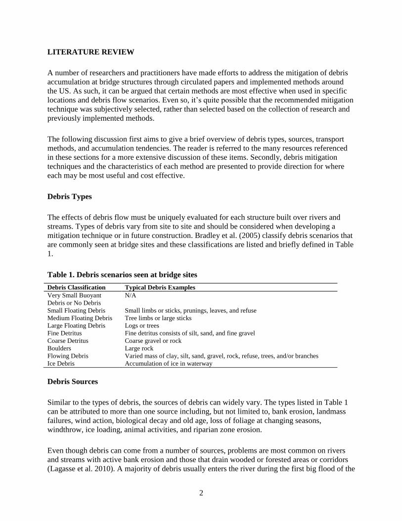
Debris fins are walls or rows of piles placed directly upstream of bridge piers for which
protection from debris accumulation is desired. Though commonly direct extensions of the
bridge pier structure – sometimes referred to as “pier nose extensions” – debris fins can also be
independent of the bridge. The fins are oriented parallel to the flow of the river to maximize
effectiveness, as a greater possibility exists for debris collection when flow is oblique to the fin.
In addition, when the debris is oriented in the direction of flow and the debris does not squarely
make contact with the pier, the impact is lessened, reducing the effects on the bridge pier
(Haehnel and Daly 2002). Note that Haehnel and Daly found the likelihood of direct impact to be
rare even when debris has been aligned with the direction of flow.
The effectiveness of fins varies and is most dependent on flow velocity. Debris fins are most
effective in higher velocity flows and have been shown to be very effective in areas where large
amounts of debris are present (Federal Preservation Institute 2002). Though largely effective,
note that debris fins may require some regular debris removal. Examples of debris fins can be
seen in Figure 1, Figure 2, and Figure 3.
Figure 1. Debris fins upstream of bridge piers (Lagasse et al. 2010)

5
Figure 2. Debris fin upstream of bridge pier (Bradley et al. 2005)
Figure 3. Debris fins independent of bridge pier structure (Bradley et al. 2005)
Methods of Mitigation
In-Channel Debris Dams and Basins
Dr. J. Knauss at the Institute of Hydraulics, Technical University of Munich, performed a study
in 1985 on what would later be coined the Treibholzfange debris detention device. His study
found that driving circular posts into the channel bed, spaced to match the minimum length of
debris for which entrapment was desired, was most effective in capturing debris without
impeding water and sediment flow. Several varying post configurations were tested in a flume.
These configurations can be seen in Figure 4.

6
Figure 4. Treibholzfange debris detention device (Wallerstein and Thorne 1997)
Knauss found the downstream pointed V (configuration 2) to best retain debris in addition to
limiting backwater effects. Debris was likely to be pushed up and over configuration 1 while, at
the same time, restricting flow and increasing backwater effects. The backwater effect of
configurations 3 and 4 were less desirable than that of configuration 2 (Wallerstein and Thorne
1997).
Another alternative to upstream debris mitigation is an in-channel debris basin (Figure 5, Figure
6, and Figure 7). These structures are placed across well-defined channels to form basins that
impede the flow and create debris storage (Bradley et al. 2005). As one might assume, these
structures have considerable capital costs and require regular maintenance and debris removal.
However, the basins effectively restrict debris from downstream structures.
Figure 5. Debris basin constructed from metal. (Bradley et al. 2005)

7
Figure 6. Debris basin constructed from gabions (Bradley et al. 2005)
Figure 7. Debris basin constructed of precast concrete sections (Bradley et al. 2005)
River Training Structures
Debris flow is primarily directed by the currents within a river, thus one can assume if the
currents can be controlled then so also can the debris. One method of controlling the river flow is
through the use of jetties or weirs. Figure 8 shows an example of weirs located on the outer bank
of a river.

8
Figure 8. Weirs on outer bank of river (Bradley et al. 2005)
Eddy currents are formed on the downstream side of the weirs thereby trapping debris in the
created vortex. Likewise, Iowa Vanes (Figure 9) perform a similar function.
Figure 9. Iowa Vanes on outer river bank (Iowa DNR 2006)
The effectiveness of each method may be specific to location as the functionality may be
lessened in locations of straight river channels. Similarly, the total cost of implementation is
greatly dependent on location as site conditions can vary considerably from site to site.

9
Kellner jacks (Figure 10) became popular in the mid-1950s and early 1960s and have been used
primarily to redirect flow patterns to reduce outer bank erosion.
Figure 10. Kellner jacks used to redirect flow patterns (Bradley et al. 2005)
A Kellner jack field will trap sediment and debris during flood events and essentially create a
levee to confine the river channel (Grassel 2002). Note that the primary function was not to trap
debris, but rather to create a levee. Even though the jacks proved effective in many locations,
more cost effective measures exist today that render the use of new jacks obsolete.
Crib Structures
Bridge piers are sometimes constructed with an open-pile configuration and debris is easily
caught and accumulates in these bents necessitating manual removal. A crib structure reduces or
eliminates the open pile configuration by creating walls with the addition of cribbing or
sheathing between the piles. When cribbing is used, the openings between boards should be
minimized to avoid trapping debris in a similar manner to the original bent. Sheathing consisting
of timber or metal is preferred as the spacing and ability to capture debris is minimized. Note that
either method is susceptible to severe damage by ice and large debris (Chang and Shen 1979).
Debris Deflectors
Debris deflectors are most often composed of steel columns driven into the river bed in a V-
shaped pattern directly upstream of the bridge pier for which protection is desired (Figure 11 and
Figure 12).

10
Figure 11. Debris deflector looking upstream (Bradley et al. 2005)
Figure 12. Debris deflector schematic (Bradley et al. 2005)

11
The V is pointed upstream and is therefore able to shed debris away from the bridge pier. One
advantage to this method when compared to the Treibholzfange detention method is the relative
size. While Treibholzfange requires driving a river-wide pattern of columns, the debris deflectors
are localized to the area of the bridge pier – a more cost effective endeavor.
Debris deflectors tend to be an open grid of vertical members with horizontal members tying
each together. The open grid allows water to pass relatively unimpeded and, though largely
effective for deflecting debris, the chance exists that debris will be captured by the deflector. As
such, one should expect some regular maintenance and debris removal.
A different configuration that has shown little success is shown in Figure 13.
Figure 13. Single column debris deflectors (Lyn et al. 2003)
Individual piles are driven into the riverbed upstream of the pier(s) with the intent to deflect
debris. Purdue University (Lyn et al. 2003) conducted a laboratory and field study specific to the
configuration and noted that in each case the piles were likely to trap, rather than deflect, debris
(Figure 14). The trapped debris proved to be even more ineffective in deflecting subsequent
debris. In the field observation, debris collection at the piles would intermittently dislodge and
form a single mass of debris that could become reestablished at the bridge pier – a largely
undesirable effect.

12
Figure 14. Debris accumulation at single column debris deflectors (Lyn et al. 2003)
Though very different from the debris deflectors previously discussed, the lunate-shaped
hydrofoil deflector created by Saunders and Oppenheimer (US Patent #5839853) is also
classified as a debris deflector (Figure 15 and Figure 16).
Figure 15. Plan view of hydrofoil deflector (Oppenheimer and Saunders 1995)

13
Figure 16. Profile view of hydrofoil deflector (Oppenheimer and Saunders 1995)
The hydrofoil sets below the surface of the water, inclined to generate vortices immediately
downstream that guide the debris past the pier. The hydrofoil is pole mounted or tethered to the
riverbed upstream of the pier and remains at a given height. In most situations, the water level
would be higher than the hydrofoil making the chances of damage from debris flow unlikely.
One disadvantage to this method, however, is the inability of the hydrofoil to rise and fall with
the water levels. When water levels fall below the hydrofoil, the hydrofoil becomes inoperative
and can be susceptible to damage from debris flows. Saunders and Oppenheimer completed
laboratory studies that proved the hydrofoil to be a viable option. Nonetheless, a hydrofoil has
never been installed in the field. (The figures show the schematic diagrams from Saunders’ and
Oppenheimer’s original.)
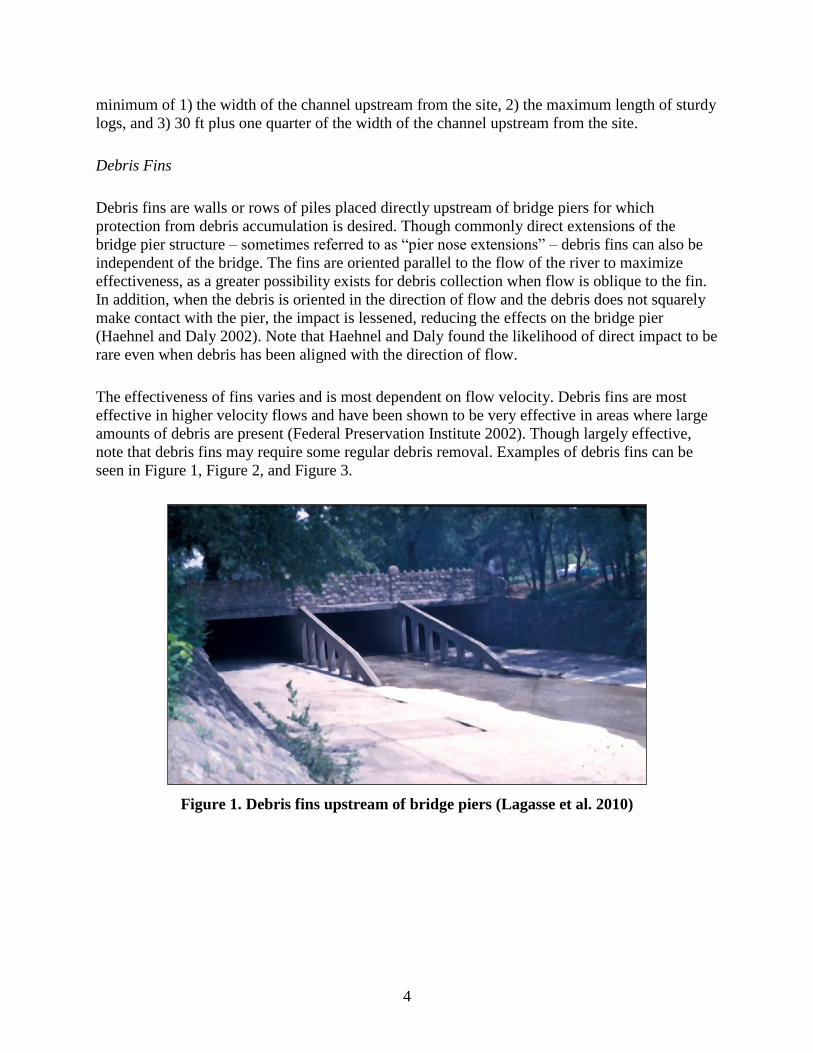
Debris Sweepers
Debris sweepers (Figure 17) were made popular by Debris Free, Inc., which holds the patent (US
Patent #6406221) and the sweepers have been used around the US in locations where debris has
been known to accumulate at bridge piers.
The sweepers are mounted directly upstream of the pier for which protection is desired and are
composed of a vertically aligned water-velocity powered turbine. The rotation of the sweeper
aims to deflect the debris to either side of the bridge pier for easier pass-through. One attractive
feature is the ability of the sweeper to rise and fall to match the water surface level, achieved by
filling the cylinder with a buoyant material.
Even though the debris sweeper proved effective in some locations, some reservations were
expressed at the 2007 spring conference of American Association of State Highway and
Transportation Officials (AASHTO). Among the observations were device failures due to
clogging, being crushed by large debris, and being dislodged from the mounts (Tyler 2011). In
addition, the effectiveness and robustness of the debris sweeper in icy conditions was questioned.
14
Figure 17. Debris sweeper (Bradley et al. 2005)
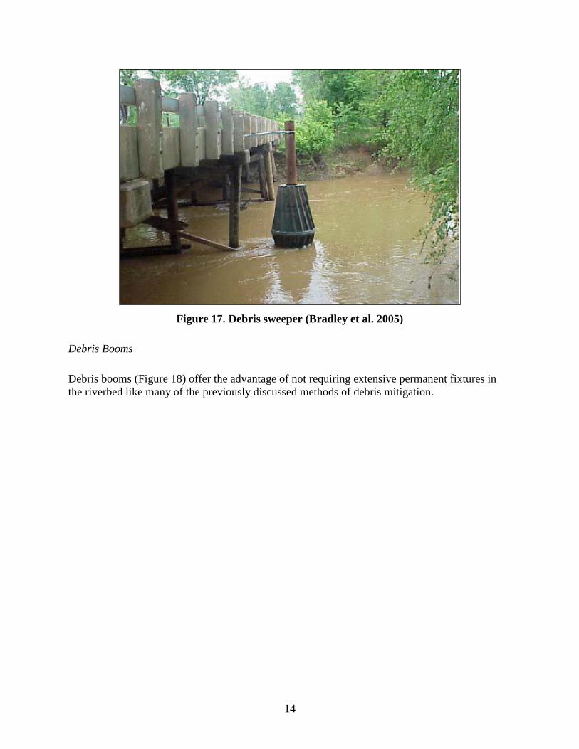
Debris Booms
Debris booms (Figure 18) offer the advantage of not requiring extensive permanent fixtures in
the riverbed like many of the previously discussed methods of debris mitigation.
15
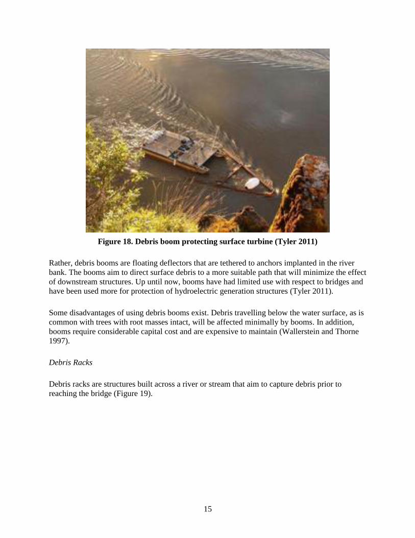
Figure 18. Debris boom protecting surface turbine (Tyler 2011)
Rather, debris booms are floating deflectors that are tethered to anchors implanted in the river
bank. The booms aim to direct surface debris to a more suitable path that will minimize the effect
of downstream structures. Up until now, booms have had limited use with respect to bridges and
have been used more for protection of hydroelectric generation structures (Tyler 2011).
Some disadvantages of using debris booms exist. Debris travelling below the water surface, as is
common with trees with root masses intact, will be affected minimally by booms. In addition,
booms require considerable capital cost and are expensive to maintain (Wallerstein and Thorne
1997).
Debris Racks
Debris racks are structures built across a river or stream that aim to capture debris prior to
reaching the bridge (Figure 19).

16
Figure 19. Debris rack installed upstream (Bradley et al. 2005)
Configurations and materials vary among many of the racks. Figure 20 and Figure 21 provide
examples of steel and timber racks, respectively.
Figure 20. Steel debris rack (Bradley et al. 2005)

17
Figure 21. Timber debris rack (Bradley et al. 2005)
Most racks are constructed vertically and at a right angle to the river flow. Others are constructed
inclined to the vertical plane, which allows debris to ride up and onto the rack, while even others
are constructed skewed to the river flow to help deflect debris towards the river banks. In
locations where significant debris exists, debris racks can become packed which impedes water
flow and creates backwater issues. The water tends to flank the debris rack eroding the bank and
potentially scouring areas downstream where reentry to the channel occurs. Additionally, debris
removal from the racks can be necessary and costly because of the inherent propensity to collect
debris, frequently more than what would be collected at a bridge pier. (Diehl 1997)
Design Features
Prior to bridge construction and where debris accumulation is anticipated, the opportunity exists
to implement design features into the bridge that will minimize mitigation efforts. Examples are
freeboard, pier type, location, and spacing, and a special superstructure.
Freeboard is the addition or maximization of space between the anticipated high water level and
the lowest member of the bridge superstructure. Accumulation of debris can hopefully be
minimized during flood events, which are especially prone to gathering debris, as the ability for
debris to be captured by the superstructure is lessened by the increased height of the water. The
recommended minimum freeboard of a bridge structure should be 2 feet where there is high
potential for floating debris. The freeboard should be increased to 3.3 to 3.9 feet where debris is
abundant and known debris problems exist (Bradley et al. 2005). The potential for increased cost
to create additional freeboard exists and, accordingly, a cost-risk analysis should be performed to
determine the optimum bridge elevation.

18
Pier type, location, and spacing can all have an impact on debris accumulation. A solid-walled
pier fairs much better when compared to an open pile bent structure as the chance for debris to be
captured is lessened. Additionally, piers that are parallel to channel flow are likely to capture less
debris as the pier area perpendicular to flow is minimized. Lastly, where possible the distance
between piers should be maximized or at least spaced a distance apart that is greater than the
anticipated design log length. This feature would avoid a single log being captured between two
piers if travelling lengthwise perpendicular to flow.
Where heavy debris flows and overtopping of the bridge are anticipated in large flood events, in
addition to designing the bridge to withstand hydrostatic forces in submerged state, one can
reduce the potential for accumulation by minimizing the profile and number of openings of the
superstructure, i.e., solid barrier walls.
Lastly, regardless of the measures one takes to mitigate debris accumulation, at least some debris
will likely be captured by a bridge structure. Providing access to the bridge to remove debris for
either annual maintenance or emergency situations can prove beneficial. The effort required to
remove debris can be costly, thus improving access may return the initial cost over time.
Debris Mitigation Method Selection
Prior to conducting any design or implementation of debris mitigation methods, a field
investigation should be completed with the purpose of understanding the debris problem at the
bridge. When available, the most useful source of information is from past flood events.
Unfortunately, this type of information rarely exists, thus requiring a thorough field investigation
to reveal the types of debris transported and better clarify the required analyses for estimation of
debris quantities. Information to assist the engineer may include soil, land use, and topographic
mapping; aerial photographs; observations of the flow characteristics near the site and any direct
and indirect evidence of high delivery potential for floating debris upstream of the site; sediment
and discharge data; and future changes in watershed (Bradley et al. 2005).
Each of the mitigation methods has certain advantages, disadvantages, and associated costs.
Determining which is best for any one bridge becomes an exercise in balancing those options.
Table 2 and Table 3, adapted from previously conducted research, each provide direction for
determining the appropriate method at a specific bridge.
Table 2 was developed to identify the abilities and best area of application for each
countermeasure, provide information for anticipated maintenance costs, and indicate aesthetic
and environmental impacts. The following types of debris used within this table are defined
previously in this report: light flowing debris, medium flowing debris, large flowing debris,
flowing debris, fine detritus, coarse detritus, and boulders.

19
Table 2. Debris-control countermeasures matrix adapted from Bradley et al. 2005
Countermeasure
Countermeasure Characteristics
Debris Classification Maintenance
Aesthetics Environmental
Impact Floating Debris
Flowing
Debris
Bed Material
Estimated
Allocation of
Resources
Light Medium Large Fine
Detritus
Coarse
Detritus Boulders
H=High
M=Moderate
L=Low
U=Undesirable
A=Acceptable
D=Desirable
H=High
M=Moderate
L=Low
Deflectors x x x H-M U L
Fins
x x
M A L
Crib Structure
x x
U L
RTS - Iowa Vanes
x
M A M
RTS - Permeable Spurs
x x x
M A M
RTS - Impermeable Spurs
x x x
H A H
In-Channel Debris Basins
x x x
H A H
Flood Relief Sections
x x
L A L
Debris Sweeper
x x
L A L
Booms x x
L U M
DF - Freeboard
x x
L D L
DF - Pier Type, Location,
and Spacing
x x
L D L
DF - Special Superstructure x x L D L
RTS=River Training Structures

20
Table 3. Debris mitigation options and review adapted from Sheeder and Johnson 2008
Option Benefits Disadvantages
Annual Cost over
10 Year Period
Maintenance
Removal of Debris
Simple Operation Required over life of bridge; disruptive of
aquatic ecosystem; accumulation during
flood events may jeopardize bridge, cause
scour and flooding
Low to Moderate
(over longer term)
Vanes/weirs
employed to direct
debris flow through
bridge opening
Following installation,
may alleviate or reduce
additional maintenance
requirements
Will lead to alteration of sediment
transport processes; if not designed
correctly, can cause aggradation or
erosion in the vicinity of the bridge.
Debris my tend to hang up on structure
Low
Debris Deflectors Simple design and
construction
May trap debris upstream of bridge
requiring maintenance removal; known to
fail under high lateral forces of trapped
debris; failure of piles may jeopardize
bridge
Low
Debris Basin Simple design,
construction, and
operation; potential to sell
collected timber and
sediment
May need to purchase land if not located
in right-of-way; requires periodic removal
of collected sediment and debris; lack of
sediment transmission may lead to
erosion downstream; may adversely
affect migratory species
Moderate to High
Debris Sweepers Active system; following
installation, may alleviate
additional maintenance
requirements; requires
little disturbance of the
stream channel
Failure of system can increase potential
for debris accumulation; not appropriate
for certain bridge configurations (if span
is less than maximum length of debris)
Low to Moderate
Crib walls, debris
fins
May not require stream
modification or
continuing maintenance
Low reliability; problem may continue;
maintenance required
Moderate
Reconfiguration of
riprap at piers
Provides more effective
scour protection as well as
debris alleviation; can
create system that
alleviates both debris and
scour
None Moderate
Channelization or
reconfiguring the
channel
Prevent debris and
sediment accumulation by
increasing rate of flow
through steepened reach
Higher velocity could cause scour at
bridge; may cause erosion of bed and
banks upstream; potential maintenance
costs associated with erosion; not
sustainable if river system is unstable
High
Removal of
unneeded upstream
infrastructure or
other obstructions
Eliminates obstructions
that may be causing
sediment and/or debris-
related problems in the
vicinity of the bridge; no
maintenance required
following removal
Removal of obstructions may create new
flow patterns, which may lead to
additional sediment and/or debris related
problems
Moderate to High

21
Maintenance costs indicated by high, medium, or low are a subjective estimation and are
compared relative to the other countermeasures within the table. A low rating indicates that the
countermeasure is relatively maintenance free; a moderate rating indicates that some
maintenance is required; and a high rating indicates that the countermeasure requires more
maintenance than most of the countermeasures in the matrix.
Aesthetically, the countermeasures have varying degrees of desirability. Like the maintenance
costs, and rated by a U-undesirable, A-acceptable, or D-desirable, the aesthetics of each
countermeasure is compared subjectively and relative to the other countermeasures within the
table. A U rating indicates a noticeably unpleasing sight, an A rating indicates that the
countermeasure is unobtrusive for the most part, and a D rating indicates the countermeasure is
pleasing to the sight (Bradley et al. 2005).
Lastly, the environmental impact rating indicates the anticipated level of effect each
countermeasure would have with respect to the other countermeasures. The ratings (low,
medium, or high) are subjectively assigned and indicate minimal effect, mild adverse effect, or
adverse effect on the environment, respectively.
Table 3 presents specific advantages and disadvantages for many of the debris mitigation
methods. In addition, the anticipated cost over a 10 year period is given in comparison to the
other methods.

22
NATIONAL SURVEY
To best determine the current state of the practice regarding debris deflection at bridges, a survey
was developed and sent out nationally to state departments of transportation. Thirty-four
responses from 31 different states were received. The questions and summary are provided
herein.
Survey Questions and Answers
Question 1: What methods of debris deflection have been used in your state?
Methods of Debris Deflection
Debris Fins Crib Structures
Debris Deflectors In-Channel Debris Basins
Debris Sweepers River Training Structures
Debris Racks None
Booms Other
Answer 1
Methods of Debris Deflection Responses
Debris Fins 2 Crib Structures 2
Debris Deflectors 11 In-Channel Debris Basins 1
Debris Sweepers 3 River Training Structures 4
Debris Racks 4 None 20
Booms 0 Other 5
Response Comments
1. For the in-channel debris basins, we have used this approach in channels with extreme
sediment accumulation, not as a wood debris provision. (Alaska)
2. During design, we try to adhere to some common practices that enhance our structure’s
potential for collecting debris. These practices include refraining from using short spans and
avoid skewed bents when significant debris is expected. Occasionally we may shape the nose
of our piers such that it helps with the deflection of the debris. (Louisiana)
3. Sloped/battered upstream pile/pier, solid pier wall/encased pile bents. (Nebraska)
4. Rounded pier ends on the upstream side. (District of Columbia)
5. Sweepers proposed but not used. (New York)

23
Question 2: Please rate the overall performance of each method you selected as Poor,
Satisfactory, Good, or Excellent
Answer 2
Overall Performance Rating
Deflection Method Poor Satisfactory Good Excellent
Debris Fins 0 2 0 0
Debris Deflectors 2 8 1 0
Debris Sweepers 2 0 1 0
Debris Racks 1 3 0 0
Booms 0 0 0 0
Crib Structures 0 2 0 0
In-channel Debris Basins 0 1 0 0
River Training Structures 0 4 0 0
Other 0 1 1 0
Response Comments
1. The debris deflectors have only been installed on a very limited number of structures.
Estimate installation occurred approximately 4 years ago, so no extensive data on
performance has been developed. (Nevada – Regarding debris deflectors)
2. We have used the indicated devices once or twice. They perform OK but we don't have a lot
of experience with them. (Georgia – Regarding debris deflectors and river training structures)
3. IDOT's 10 - 15 sweepers are the Debris Free bridge sharks or MOABS. Very scattered
performance. Various failure modes- ice is most common. Debris racks are very few in
number. (Illinois – Regarding debris sweepers and debris racks)
4. In cold climates, debris racks (particularly at culvert inlets) can promote frazil ice
accumulation, potentially leading to a blockage. (Alaska – Regarding debris racks)
5. One installation in FDOT District 3 on SR4 over Escambia River did not perform well. Low
flow conditions during drought probably made things worse. (Florida – Regarding debris
deflectors)
6. The sloped upstream end of the pier/bent/pile helps to keep any debris at or above the water
surface. (Nebraska – Regarding other methods)
7. In Minnesota District 7 Mankato we used two different debris removal devices made by
Debris Free from California. The smaller device the shark could not stand up to the large
trees that flowed past our bridges on the Minnesota River. I would call the smaller device the
bridge sharks a sweeper and it had a poor performance. The larger device, the MOAB
(Mother Of All Bridge sharks), I believe could have had a better performance had it not been
for the piling installation. The smaller shark was mounted on a stainless steel rail system. The
MOAB was designed to be mounted on a pile system. Both systems were designed to allow
the device to rise and lower according to the water level. Because of poor welds on piles our
MOAB's were mounted they failed. Before the large debris pile caused the failure, the
MOAB system was deflecting timber debris. (Minnesota – Regarding debris deflectors)
8. There were some issues with maintenance. (Florida – Regarding debris deflectors)
9. No survey was conducted to rate the performance of the practice. (District of Columbia –
Regarding rounded pier noses on upstream side)

24
Question 3: Please rate the overall cost effectiveness of each method you selected as Poor,
Satisfactory, Good, or Excellent
Answer 3
Overall Cost Effectiveness Rating
Deflection Method Poor Satisfactory Good Excellent
Debris Fins 0 1 1 0
Debris Deflectors 2 7 0 0
Debris Sweepers 3 0 0 0
Debris Racks 1 3 0 0
Booms 0 0 0 0
Crib Structures 0 2 0 0
In-channel Debris Basins 0 0 1 0
River Training Structures 0 3 1 0
Other 0 1 1 0
Response Comments
1. Long-term maintenance burdens and costs should be considered. (Alaska – Regarding
general debris mitigation)
2. Appears to minimize accumulation of debris (Nebraska – Regarding sloped upstream and of
piers, bents, and piles)
3. Could have been better for the MOAB if it wasn’t for pile failure (Minnesota – Regarding
debris sweepers)
Question 4: Have pier design methods been used in your state specifically to mitigate debris
accumulation at bridges?
Answer 4
Pier Design Methods Specifically Used to Mitigate
Debris Accumulation
No Yes
Pier Design Methods Have Been Used 23 13
Response Comments
1. Vermont does not use multi-column piers in stream. The piers are either solid wall piers
aligned with the flow of the stream or single circular column piers. (Vermont)
2. Rounded pier noses. Use of wall-type piers when feasible. (Utah)
3. Older bridges often feature concrete infill walls, which can help reduce wood debris
accumulation. Newer bridges tend to have the (open) multi-pile bents or drilled shafts.
(Alaska)
4. Attempts are made not to locate piers within the main channel, to use longer spans in the
channel area, and to use single column bents in the channel area. (Arkansas)
25
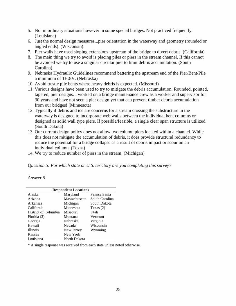
5. Not in ordinary situations however in some special bridges. Not practiced frequently.
(Louisiana)
6. Just the normal design measures...pier orientation in the waterway and geometry (rounded or
angled ends). (Wisconsin)
7. Pier walls have used sloping extensions upstream of the bridge to divert debris. (California)
8. The main thing we try to avoid is placing piles or piers in the stream channel. If this cannot
be avoided we try to use a singular circular pier to limit debris accumulation. (South
Carolina)
9. Nebraska Hydraulic Guidelines recommend battering the upstream end of the Pier/Bent/Pile
a minimum of 1H:8V. (Nebraska)
10. Avoid trestle pile bents where heavy debris is expected. (Missouri)
11. Various designs have been used to try to mitigate the debris accumulation. Rounded, pointed,
tapered, pier designs. I worked on a bridge maintenance crew as a worker and supervisor for
30 years and have not seen a pier design yet that can prevent timber debris accumulation
from our bridges! (Minnesota)
12. Typically if debris and ice are concerns for a stream crossing the substructure in the
waterway is designed to incorporate web walls between the individual bent columns or
designed as solid wall type piers. If possible/feasible, a single clear span structure is utilized.
(South Dakota)
13. Our current design policy does not allow two column piers located within a channel. While
this does not mitigate the accumulation of debris, it does provide structural redundancy to
reduce the potential for a bridge collapse as a result of debris impact or scour on an
individual column. (Texas)
14. We try to reduce number of piers in the stream. (Michigan)
Question 5: For which state or U.S. territory are you completing this survey?
Answer 5
Respondent Locations
Alaska Maryland Pennsylvania
Arizona Massachusetts South Carolina
Arkansas Michigan South Dakota
California Minnesota Texas (2)
District of Columbia Missouri Utah
Florida (3) Montana Vermont
Georgia Nebraska Virginia
Hawaii Nevada Wisconsin
Illinois New Jersey Wyoming
Kansas New York
Louisiana North Dakota
* A single response was received from each state unless noted otherwise.

26
Table 4. Survey results summary
Location
Debris
Fins
Debris
Deflectors
Debris
Sweepers
Debris
Racks
Crib
Structures
In-
Channel
Debris
Basins
River
Training
Structures Other None
Meth
od
Use
d
Perfo
rm
an
ce
Co
st E
ffec
tiv
en
ess
Meth
od
Use
d
Perfo
rm
an
ce
Co
st E
ffec
tiv
en
ess
Meth
od
Use
d
Perfo
rm
an
ce
Co
st E
ffec
tiv
en
ess
Meth
od
Use
d
Perfo
rm
an
ce
Co
st E
ffec
tiv
en
ess
Meth
od
Use
d
Perfo
rm
an
ce
Co
st E
ffec
tiv
en
ess
Meth
od
Use
d
Perfo
rm
an
ce
Co
st E
ffec
tiv
en
ess
Meth
od
Use
d
Perfo
rm
an
ce
Co
st E
ffec
tiv
en
ess
Meth
od
Use
d
Perfo
rm
an
ce
Co
st E
ffec
tiv
en
ess
Alaska X S S X S S X S G X S S
Arizona
X
Arkansas X
California
X G S X G P X S S
DC X S S
Florida
X P/S S
Georgia X S S X S S
Hawaii
X
Illinois X P P X S S
Kansas X S G
X S S
Louisiana X
Maryland
X
Massachusetts X
Michigan
X
Minnesota X S P X P P
Missouri
X P P
X S S
Montana X
Nebraska X
Nevada X S
New Jersey
X
New York X
North Dakota
X
Pennsylvania X
South Carolina
X
South Dakota X
Texas
X
Utah X S S X S S X P P
Vermont
X
Virginia X
Wisconsin
X S S
Wyoming X S S X S G
Unknown X S S
X = Used, S = Satisfactory, G = Good, P = Poor

27
Survey Observations
By the survey responses received, evidence is provided that only a fraction of the states have
attempted some method of debris mitigation. The apparent need for mitigation is clear for some
states, yet others may have minimal or no need at all. Overall, the entirety of the United States
was fairly well represented as there was no region where at least one response was not received.
Of all the methods listed, debris deflectors were most commonly implemented and with varying
success. The states that have used this method rated the performance as satisfactory, aside from
California and Missouri, which rated the performance as good and poor, respectively. It should
be noted that the cost effectiveness of debris deflectors was never rated higher than satisfactory
in all cases.
Alaska has attempted more of the listed methods of mitigation than any other state; debris racks,
crib structures, in-channel debris basins, and river training structures have been used. In each
case, the performance and cost effectiveness was rated as satisfactory, excluding in-channel
debris basins where the cost effectiveness was rated as good.
The performance of any one debris method was never rated higher than good. Those receiving a
performance rating of good were debris deflectors and debris sweepers in California.
Likewise, the cost effectiveness of any one debris mitigation method was never rated higher than
good. Those receiving a rating of good were in-channel debris basins in Alaska, debris fins in
Kansas, and river training structures in Wyoming.
Four states implemented mitigation techniques that were rated as poor for both performance and
cost effectiveness. Illinois, Minnesota, Missouri, and Utah rated debris sweepers, debris
sweepers, debris deflectors, and debris racks as poor, respectively.
Only one state rated the performance of one method as good and the cost effectiveness of that
same method as poor. California rated debris sweepers in this way.
Five locations indicated that other methods of debris mitigation were implemented. These
methods included rounded pier nose at upstream side (District of Columbia), singular circular
piers (South Carolina and Vermont), and solid wall type piers (South Dakota and Vermont).
Texas did not indicate what other method of debris mitigation was used.

28
CONCLUSION
The apparent effects of debris accumulation on bridge structures have made it clear that a need
for debris mitigation exists. Without mitigation, bridge structures are susceptible to scour,
overloading, or even collapse. The objective of this report has been to present methods used
currently or in the past to prevent debris-inflicted damage.
Many options exist and have been tried with varying degrees of success. Be that as it may, there
is no apparent “best” option, as site-specific conditions often determine the performance of any
one system. For this reason, it would be wise for any engineer to first study the debris source,
transport characteristics, and accumulation tendencies at a single bridge location. Other factors
including maintenance costs, aesthetics, and environmental impacts must also be considered.
With this knowledge and consideration, along with the previous accounts of successes and
failures, a mitigation option can be selected that best addresses the situation and need.
29
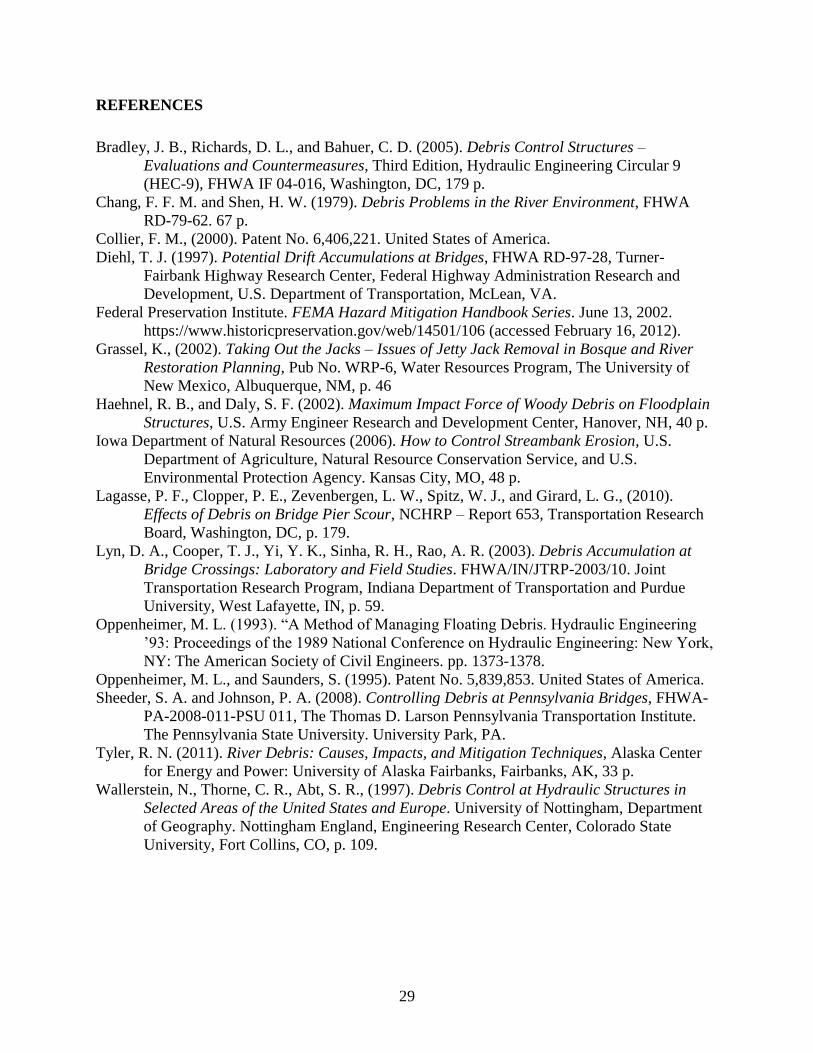
REFERENCES
Bradley, J. B., Richards, D. L., and Bahuer, C. D. (2005). Debris Control Structures –
Evaluations and Countermeasures, Third Edition, Hydraulic Engineering Circular 9
(HEC-9), FHWA IF 04-016, Washington, DC, 179 p.
Chang, F. F. M. and Shen, H. W. (1979). Debris Problems in the River Environment, FHWA
RD-79-62. 67 p.
Collier, F. M., (2000). Patent No. 6,406,221. United States of America.
Diehl, T. J. (1997). Potential Drift Accumulations at Bridges, FHWA RD-97-28, Turner-
Fairbank Highway Research Center, Federal Highway Administration Research and
Development, U.S. Department of Transportation, McLean, VA.
Federal Preservation Institute. FEMA Hazard Mitigation Handbook Series. June 13, 2002.
https://www.historicpreservation.gov/web/14501/106 (accessed February 16, 2012).
Grassel, K., (2002). Taking Out the Jacks – Issues of Jetty Jack Removal in Bosque and River
Restoration Planning, Pub No. WRP-6, Water Resources Program, The University of
New Mexico, Albuquerque, NM, p. 46
Haehnel, R. B., and Daly, S. F. (2002). Maximum Impact Force of Woody Debris on Floodplain
Structures, U.S. Army Engineer Research and Development Center, Hanover, NH, 40 p.
Iowa Department of Natural Resources (2006). How to Control Streambank Erosion, U.S.
Department of Agriculture, Natural Resource Conservation Service, and U.S.
Environmental Protection Agency. Kansas City, MO, 48 p.
Lagasse, P. F., Clopper, P. E., Zevenbergen, L. W., Spitz, W. J., and Girard, L. G., (2010).
Effects of Debris on Bridge Pier Scour, NCHRP – Report 653, Transportation Research
Board, Washington, DC, p. 179.
Lyn, D. A., Cooper, T. J., Yi, Y. K., Sinha, R. H., Rao, A. R. (2003). Debris Accumulation at
Bridge Crossings: Laboratory and Field Studies. FHWA/IN/JTRP-2003/10. Joint
Transportation Research Program, Indiana Department of Transportation and Purdue
University, West Lafayette, IN, p. 59.
Oppenheimer, M. L. (1993). “A Method of Managing Floating Debris. Hydraulic Engineering
’93: Proceedings of the 1989 National Conference on Hydraulic Engineering: New York,
NY: The American Society of Civil Engineers. pp. 1373-1378.
Oppenheimer, M. L., and Saunders, S. (1995). Patent No. 5,839,853. United States of America.
Sheeder, S. A. and Johnson, P. A. (2008). Controlling Debris at Pennsylvania Bridges, FHWA-
PA-2008-011-PSU 011, The Thomas D. Larson Pennsylvania Transportation Institute.
The Pennsylvania State University. University Park, PA.
Tyler, R. N. (2011). River Debris: Causes, Impacts, and Mitigation Techniques, Alaska Center
for Energy and Power: University of Alaska Fairbanks, Fairbanks, AK, 33 p.
Wallerstein, N., Thorne, C. R., Abt, S. R., (1997). Debris Control at Hydraulic Structures in
Selected Areas of the United States and Europe. University of Nottingham, Department
of Geography. Nottingham England, Engineering Research Center, Colorado State
University, Fort Collins, CO, p. 109.