dealing with crisis – solving engineering … engineering failures in...dealing with crisis –...
TRANSCRIPT

DEALING WITH CRISIS – SOLVING ENGINEERING FAILURES IN FORMULA 1 MOTOR RACING.
Gary Savage,
Honda Racing F1 Team
ABSTRACT
Since the early 1990s the design and operation of Formula 1 racing cars has moved from the traditional empirical approach to one which is far more numerical, particularly with the introduction of finite element stress analysis codes, computer simulation, control and monitoring systems. The difference between the quickest and slowest cars on an F1 circuit is around 1.5 seconds in an average lap time of 80-90seconds, only 1.2%. In the level below (GP2) the difference is 4-6% yet they all have essentially the same car! The sport has therefore developed into a “technology war” as the teams search for the “unfair advantage” with which to defeat their opponents. Much of the chassis technology is derived from or similar to that in the aerospace industry due to their similarity of purpose, their designs being both weight and stiffness critical. Approximately 80% of the testing of a modern Formula 1 car takes place in the laboratory either on test rigs or virtually via computer simulation. The pace of development within the sport is breathtaking; if a car were to win the first race and not be upgraded, by the end of the season it would not only be last, it would be lapped! The car which is last on the grid at the first race of a new season would be of adequate performance to have been on pole position and won the last race of the previous season. Although the performance difference between the whole grid is only 1.2%, we must add on average 1% of performance per race just to stand still. This is best summed up in a single statement; “If I would have had this year’s car last year I would have won every race!” Successful teams must therefore embrace the very latest technology and use it in highly stressed situations. Driven by the intense pressure of competition, our ability to build and operate systems sometimes runs in advance of our ability to fully understand them. We operate a “zero defects” total quality management (TQM) process throughout the team, enabling full traceability from raw materials through to obsolescence using our ERP. Parts are required to be managed and conformance guaranteed throughout their life wherever they are in the world and under whatever service conditions. Processes and procedures are put in place which to the best of our skill and ability, prevent failure. Sometimes however things do go wrong. Under such circumstances there must be a robust process which is quickly implemented to solve the problem and affect a solution. This process will be illustrated with worked examples. 1. INTRODUCTION The Formula 1 racing season runs from March until October every year. The teams involved generally release a complete new car in late January/early February, followed by an intense period of winter testing. During the season something of the order of 75% of the vehicle’s components will be changed or modified in some way in order to improve its performance and reliability throughout the season. This continual development is the key to success. As a consequence there is a need to establish rapid confidence in new designs which can only be achieved by improving the overall effectiveness of the design and development cycle. Track time is extremely limited and expensive. It is important therefore that the time spent at the circuit is concentrated on performance. Formula One is a very low-volume application. Teams produce limited quantities of small, highly complex parts. Many of the cars’ components and assemblies are very highly stressed necessitating the
highest quality manufacturing processes and technologies. Similarly the frantic need to develop performance means that time is the primary enemy of the team. Metallic components and the master patterns for composite parts are milled and turned directly from CAD data (1) (Figures 1 & 2). It is worth remembering that methods and materials used are not the major cost prohibitor despite a commonly held misconception that F1 relies on “exotic” technology with no application to the “real world” Carbon fibre which makes up the majority of the cars’ chassis (2) is now a common material in aircraft, wind turbines and sporting goods for example (Figure 3). Although the manufacture of parts is a skilled and laborious process, the costs of production are dwarfed by the costs of design, development, testing and quality control. Within our team we operate a total quality management (TQM) process, “lifing”
Anales de Mecánica de la Fractura 26, Vol. 2 (2009)
617

(monitoring and documenting) major components through every aspect of their service life from conception to obsolescence. The history of each component is extensively recorded. Designs are laboratory tested both destructively and non-destructively, with individual components and sub-assemblies being subjected to simulated loads of an entire season’s racing.
Figure 1: Suspension “upright” machined from solid.
Figure 2: Machining a composite pattern.
Figure 3: Composite competition kayaks and paddles.
Components are also “condition monitored” (mechanically and non-destructively tested) every 2750km in order to highlight any time-dependent structural degradation before it becomes a problem or to verify the integrity of repairs. They are considered to have failed if they have broken under load, have lost more than 5% of their original stiffness or exhibit ant irregularities during NDT examination. All of the data is stored and continually updated using the team’s ERP system which covers all aspects of operations (3). There is a price to be paid for conformance. Investment is required in time, capital and personnel to operate and maintain a TQM process, which must be constantly upgraded in parallel with evolving technology. The price of conformance is however far lower than the price of non-conformance; a team whose cars consistently fail cannot hope to compete at the highest level. Honda racing F1 team have invested millions of pounds in a state of the art test lab and its attendant TQM system. During the 2006 season the team uniquely experienced zero chassis failures during the racing season. Nevertheless, the nature of the sport with development driven by intense competition means there is a tendency for our ability to produce parts to run ahead of ability to fully understand them. Despite all of the processes put in place to guarantee the safety and quality of the cars, there will always be a finite probability of failure. What the systems do is continually reduce that probability within an acceptable and manageable level and enable us to correct faults quickly and professionally when they do occur. 2. TESTING AND VERIFICATION FOR THE CIRCUIT One aims to have completed all of the durability testing and the majority of the optimisation of new developments before they leave the factory. The latest Computer Aided Design (CAD) systems have the facility for rapid structural analysis but make many assumptions on a complex structure. The accuracy of the process from conceptual design to final component must therefore be thoroughly verified. Consequently more and more data is required, concerning for example spring rates, damper performance and suspension stiffness etc., all of which must be measured. The development of accurate and repeatable testing techniques is thus critically important to the acceleration of the validation process.
Anales de Mecánica de la Fractura 26, Vol. 2 (2009)
618

The purpose of the laboratory testing includes evaluation of new cars and components, and the collection of data to aid future design and race set-ups. It should always be remembered that however accurate the testing, it is only a simplistic model of what is actually occurring and the final validation will always be the performance on the circuit. Despite that, laboratory testing offers a number of significant advantages over track testing. During the development of aircraft 90% of flight testing is now out under laboratory and computer simulation conditions and Formula 1 has, over the last decade or so, followed the same route. Apart from the initial capital investment laboratory testing is relatively cheap. The operation may be carried out in complete secrecy and, of course, is not subject to the weather. However proficient a test driver, his work will never be 100% reproducible unlike a test rig. Most importantly, the laboratory test allows a far greater level of safety especially when testing new components whose failure on the track could have catastrophic results. The use of computers and digital electronics enables the single and multi axial testing of the various constituents of the car and the efficient transfer of data (4). Calculated loads are the maximum (highest tensile) and minimum (highest compression) loads resulting from the load case calculations, resolved into the principal axes of individual suspension components. The design load is the lowest load at which any component is permitted to fail; Design load = calculated load x safety factor .
Proof testing is the application of a load, lower than the design load but higher than the calculated load to which the component is required to be subjected prior to being deemed fit for purpose. Each component is loaded in both tension and compression along its major axes to a minimum safety factor of 1.3. In certain cases (particularly push rods) tensile test loads which are far higher than required for operational safety are applied in order to test the integrity of the adhesive bonds. Durability testing is the application of dynamic loads to a component or subassembly in order to evaluate any potential lifing problems. The load may be applied in the form of a fixed sinusoid oscillating between the maximum and minimum loads, a block sequence programme built up from the estimated stressing regime or the application of service data. Proof testing
and simple uniaxial durability testing may be carried out within the confines of a universal test frame (Figure 4). Service load simulation exercises on major assemblies on the other hand require expensive bespoke multi-axis test rigs. For multi-axis testing purposes, forces or motion parameters such as acceleration, velocity and displacement can be measured. Loads etc., recorded using transducers on the car, may be manipulated using appropriate software such that they may be replayed to control the servo hydraulic actuators. Using this technology it is possible to test a component or subassembly under similar conditions to those it would experience on the race circuit. Thousands of kilometres of any track may then be completed without the parts having to leave the factory! Furthermore, the digital operation of the equipment allows the programming of safety factors with relative ease and the huge relative increase in the “virtual” speed of the laboratory test compared with that on the circuit enables a significantly accelerated programme. The 12 axis test rigs (5) the team use for this purpose may achieve speeds equivalent to the car operating at 6000kmh-1 (figure 5).
Figure 4: Single axis proof test.
Figure 5: Multi-axis durability test.
Anales de Mecánica de la Fractura 26, Vol. 2 (2009)
619

3. PRODUCTION CONSIDERATIONS One of the drawbacks of Formula 1 manufacturing is that parts are generally produced in short runs by inefficient multi-step batch processing. The performance dominated nature of the business and the demands of time are such that it is very difficult to introduce the sort of efficiency drives that are commonplace in “mainstream” engineering. In terms of quality however this is a positive boon in that it is more than feasible to 100% inspect components not only when finished, but at
every stage in the production where value is added. The TQM process also allows each of these operations and checks to be documented and stored. Composite structures for example may be analysed using techniques such as DSC and DMA (Figure 6) (6) when they enter the building as prepreg raw material (7), after cure and during the various assembly stages using adhesives (8) in order ensure quality. Similarly, a whole series of NDT evaluation may be carried out at each production step (Figures 7 & 8).
Figure 6: DSC and DMA instruments.
Figure 7: X-ray NDT.
Anales de Mecánica de la Fractura 26, Vol. 2 (2009)
620

Figure 8: Ultra-sonic NDT. In-service component failure represents the most serious problem we can possibly encounter in the running of the race and test cars. Aside from the obvious concerns of driver safety and effects on operational logistics, its implications may also be manifest in the need to redesign and replace broken parts. The “lifing” process operated by the team seeks to provide a system to ensure, to the best of our skill and ability, the total quality management of all Class A components on the cars in order to maximize safety and reliability. A Class A component is defined as one that should it fail would cause the driver to lose control of the vehicle. All of those components subjected to statutory FIA safety tests (9) and requirements are also defined in the Class A category. “Lifed” parts are those components whose integrity is deemed critical to the safety and/or operation of the car. These parts must be fully condition monitored through the entirety of their service history and their service life limited to that which can be guaranteed through calculation and testing. The TQM process operated by the team for such pieces is:- 1. All aspects of manufacture and
exploitation must be fully traceable (a process known as “lifing”).
2. A representative sample of parts must be fully tested in the laboratory in order to prove that they meet design criteria for load bearing and other properties.
3. A representative sample of parts must be fully tested in the laboratory in order to prove that they are capable of surviving a simulation of a season’s operation without deterioration in any way.
4. A car set of parts must complete a
minimum of 1000km of trouble free operation on a test car.
5. Following a service interval of 2750km (an arbitrary figure chosen to approximate to 2 tests or 3 races) parts must be returned to the factory for full proof and NDT inspection.
6. Only those components that show no deterioration may be returned to service.
TQM procedures are developed during the prototyping phase of a new component or subassembly. They tend to be periodically modified and improved as the technology develops, newer more specialised applications are introduced and through feedback from operators. It is important understand the concept of a “process” in this context: A process is a series of operations which is developed such that it represents the “best practice” for the task involved. It will therefore have no end (unlike a programme or project) since it will constantly evolve along with the technology. The consequence of this integration of all aspects of laboratory, manufacturing and exploitation into a single TQM system has been a reduction of service failures to a very low level despite an ongoing process of weight reduction (and corresponding increase in stress) and the scrapping of parts to almost zero (3).
Anales de Mecánica de la Fractura 26, Vol. 2 (2009)
621

4. PROCEDURE FOR THE INVESTIGATION OF COMPONENT FAILURES DURING SERVICE Over recent years we have gone to great lengths to introduce and develop the “Class A Parts System” in order to enhance the reliability and safety of Honda race cars. Whilst this process minimizes the probability of mechanical failure, it does not and indeed cannot, reduce that probability to zero. It is paramount therefore that should any component failures occur; they are properly investigated so that the appropriate action can be taken. All failed components are reported immediately to the Operations Director (responsible for production, and quality) and Deputy Technical Director (responsible for design) by the Chief Engineer (head of track operations). It is important that the chain of command is well defined and properly enforced. In these days of instant access to various forms of Information Technology it is too easy for “well meaning individuals” to convey a fraction of the story in the wrong quarters thus blurring the investigation and delaying the solution. The report must include not only parts that have obviously failed, but also those destroyed in “racing incidents” and crashes due to driver error etc in order that it can be confirmed that damage was a consequence of the incident and not a cause and so that replacement parts can be sanctioned. The chief track engineer is required to e-mail a written account of the events leading up to the failure and any subsequent findings ASAP, to include:- • Date • Venue • Function (race/test etc.) • Climatic conditions • Action of the car at the time • Consequences (large shunt, car ground to a
halt, caused major assembly to fail etc.) • As many photographs as possible of the
offending items and subsequent damage. • Any other details deemed important.
Of paramount concern is a true and proper account of the event, concentrating purely on the facts, refraining from any conjecture, which could prejudice the investigation. This is true in any failure investigation but must be particularly emphasised in highly visible
pressurised situations such as Formula 1. Where possible the damaged components should be left in-situ so that they can be subsequently dismantled in the laboratory. In situations where this is not possible, the broken parts and those intimately attached are carefully removed without interfering with any of the evidence. All broken parts are returned ASAP to the Team Operations Centre to enable a full investigation. Components that are found to be damaged or defective during assembly or routine checking at the factory are also referred to R&D (by the appropriate head of department) and the Operations Director and Deputy Technical Director briefed on the situation. It is the responsibility of the Operations Director to identify the fault, instigate a “tactical” repair where possible and brief the Deputy Technical Director to enable him to instigate a long term solution. Any modifications and recommendations etc. will be communicated to those involved once the investigation has been concluded. The responsibility of the Deputy Technical Director and his design team is to implement a “strategic” long term solution and see that is quickly communicated to all concerned. Any redesigns to components are documented and executed via the ERP system. The quality of an F1 team and its processes ensure that failures seldom occur and when they do they are not due to poor design and manufacture but rather some unforeseen issue. The TQM system allows us to very quickly home in on the problems which are generally easily rectified. 5. CRACKED HYDRAULIC MANIFOLD The hydraulic system on the car controls many of its functions such as gear change, clutch and steering for example. If it fails then the car stops, essentially it “dies”. During winter testing prior to the 2008 season a leak developed in the system (Figures 9 & 10). Failure occurred due to a fatigue crack developing in the hydraulic manifold at the feeding joint boss, stopping the car on the circuit (Figures 11 & 12). The crack initiation point was the root of the final engaged thread. There was no obvious surface damage or material defects observed at crack initiation and the material analysis satisfied all of the team’s specifications. Ordinarily in such a situation one would suggest strengthening the component by redesigning with increased material in the offending area The incident occurred however after only 1293km of
Anales de Mecánica de la Fractura 26, Vol. 2 (2009)
622

running despite an identical component having run in excess of 6000 simulated km on the powertain system (PTS) dyno (Figure 13). The PTS dyno is able to simulate the running of the car at any circuit, under any weather conditions, even race starts, pit lane simulations, safety car procedures and spin turns. It was concluded therefore that the crack
was initiated by bending overstress due to vibration which was found to be different between car and dyno. The elastomeric mounts used to damp the vibration between manifold and engine were changed and the problem was solved.
CrackCrack
Figure 9: Hydraulic manifold. Figure 10: Location of crack.
Figure 11: Crack detail.
Fatigue crackpropagation
Fatigue crackpropagation
Fatigue crackpropagation
Fatigue crackpropagation
Figure 12: SEM examination of crack in hydraulic manifold.
Crack
Anales de Mecánica de la Fractura 26, Vol. 2 (2009)
623

Figure 13: PTS Dyno. 6. BROKEN REAR RACK ROD During practice for the 2008 British Grand Prix one of the team’s drivers detected a problem with the handling of his car and returned to the pits.. An examination revealed that one of the rear track rods on the car had broken (Figure 14). A report was immediately filed to the Operations Centre and an investigation begun. X-ray, optical and electron microscopy found no evidence indicating the component to be defective in any way (Figure 15). Mechanical proof tests and NDT on all other components of the same type were found to be defect free and within specification (Figure 16). Failure was found to have occurred due to a single tensile overload. Analysis of track data showed that the high frequency/low amplitude vibration loads resulting from riding kerbs with “rumble strips” which had recently been added to the circuit could generate loads beyond those for which the track rods were designed (20% higher). A short term solution was to apply a reinforcing patch increasing the tensile strength of the component by 32% (Figure 17). The longer term solution was a redesign of the component to make it 60% stronger (Figure 18).
Figure 14: Broken rear track rod.
Anales de Mecánica de la Fractura 26, Vol. 2 (2009)
624
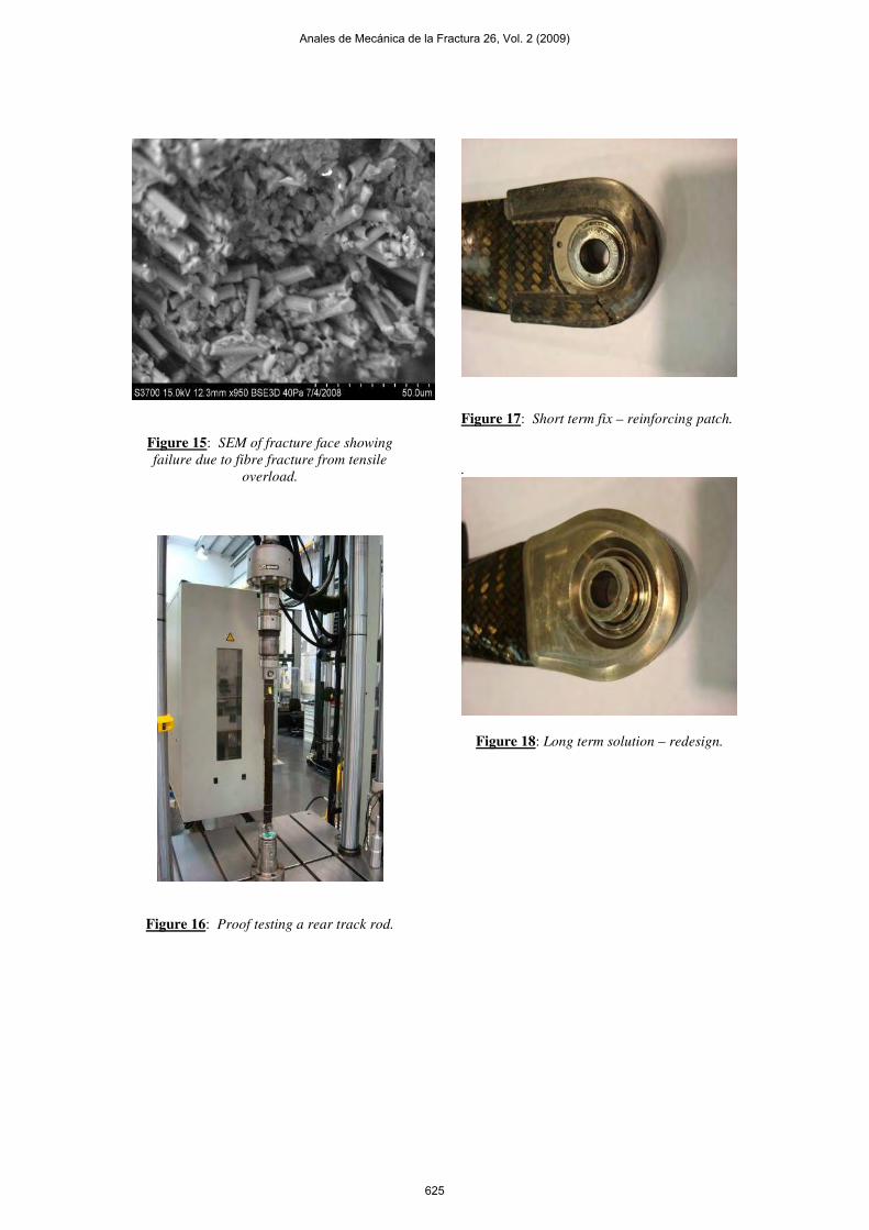
Figure 15: SEM of fracture face showing failure due to fibre fracture from tensile
overload.
Figure 16: Proof testing a rear track rod.
Figure 17: Short term fix – reinforcing patch. .
Figure 18: Long term solution – redesign.
Anales de Mecánica de la Fractura 26, Vol. 2 (2009)
625

7. SUMMARY A modern Formula 1 chassis consists of a series multi-material structures, primarily although by no means always incorporating fibre reinforced composites mouldings bonded with adhesives. Many of these structures are very highly stressed and required to operate in aggressive environments, particularly high temperatures. The consequences of failure of “Class A” structures can be catastrophic to the operation of the vehicle and impinge on the safety of the driver. Although increasingly better understood, the science and engineering of much of the technology employed is still in its infancy. Consequently their design and operation of many of the components tends to be a constantly evolving, semi-quantitative process combining fracture and finite element analysis with practical experience. One may easily understand therefore the traditional reluctance amongst engineers operating in areas where the driving force for new technology is not so strong to fully embrace many of the practices common in Formula 1. The use of structural adhesives for example is limited primarily due to the fear of catastrophic failure. The widespread application of bonded joints in performance critical applications on F1 cars shows just how useful adhesives can be. It would not be unreasonable to suggest that components manufactured using bonded joints are generally superior to those assembled using more traditional joining technologies. Indeed, many of the assemblies common on contemporary F1 cars simply could not be made any other way. There is however a very significant “price of conformance” which must be paid in order to ensure the long-term durability of such structures and joining methodologies. The lack of numerical design and robust data demand a very sophisticated TQM process is in operation if the integrity of parts is to be maintained. Production controls are paramount if the advantages of new materials and technologies are to be successfully exploited. Attention to detail in manufacture is vital to ensure enhanced mechanical performance, improved durability, and increased service life of components. The integrity of adhesive joints can only be guaranteed by observing a “zero defects” approach to quality control.
It must always be remembered that however through the processes and procedures, there is always a finite probability that something unexpected could occur. The exploitation of any new techniques and technology will always be associated with a degree of risk. The key to a successful solution is minimise and manage the risk to an acceptable level and always ensure there is an emergency recovery procedure in place for the few occasions when things do go wrong. It could be argued that the true measure of engineering prowess is how one “deals with disaster”. In such difficult times procedure and discipline are vital to prevent a drama becoming a crisis. A sound appreciation of the situation and strict adherence to the emergency process are the best route to a successful solution. The implementation and management of change is a key factor in successful engineering and will always be associated with a degree of risk. Without risk there is no progress but too great a risk will lead to disaster. Difficult decisions always have, and always will be the privilege of high command. REFERENCES 1. Savage, GM. Proc “Carbon fiber 2007”,
Washington DC, USA. (Dec 2007). 2. Savage, GM., J. STA., 140, 18 (2000). 3. Savage, GM submitted to “Engineering
Failure Analysis” (2009). 4. Savage, GM. and May, S., J.STA. 136, 35
(May/Jun 1999). 5. Savage, GM. Proc. “Transfac 06” San-
Sebastian, Spain (Oct 2006). 6. Savage GM. and Cox, P. Automotive
engineering 2, 22 (1992). 7. Savage GM, Proc SPE Automotive
Conference, Troy MI, USA (Sep 2008). 8. Savage, GM., Engineering Failure
Analysis, 14, 2, 321 (2007). 9. Savage, GM., Proc. Anales De Mecanica
de la Fractura, 18, 274, Baiona (Vigo), Spain, (Mar. 2001).
Anales de Mecánica de la Fractura 26, Vol. 2 (2009)
626