de2 electronic keyboard readmefirst...de2 board into an electronic piano. in part 1 of the lab, you...
TRANSCRIPT
DE2 Electronic Keyboard
ReadMeFirst
Lab Summary:
In this lab, you will implement a two-tone electronic keyboard using the waveform synthesizer design from the previous lab.
This lab is divided into two projects. In the first, you will make a single channel keyboard. In the second project, you will use hierarchy to add another channel to the circuit. Once you build the first channel and understand how it works, adding the second channel is relatively simple.
Lab Background:
In the last lab you transformed the DE2 Board into a signal generator. Now you will transform the DE2 Board into an electronic piano. In Part 1 of the lab, you will make a single channel keyboard. You will be given a keyboard with a PS/2 interface that will be re-mapped to play the desired notes. You are provided with a Verilog file (PS2_KEYBOARD.v) that will read the input from the PS2 keyboard and output a keycode. When you press one key, the first channel will play the note. When you hold one key and press another key, the second channel will play the note. In the next lab this feature will be used to make harmony parts in an automated play design.
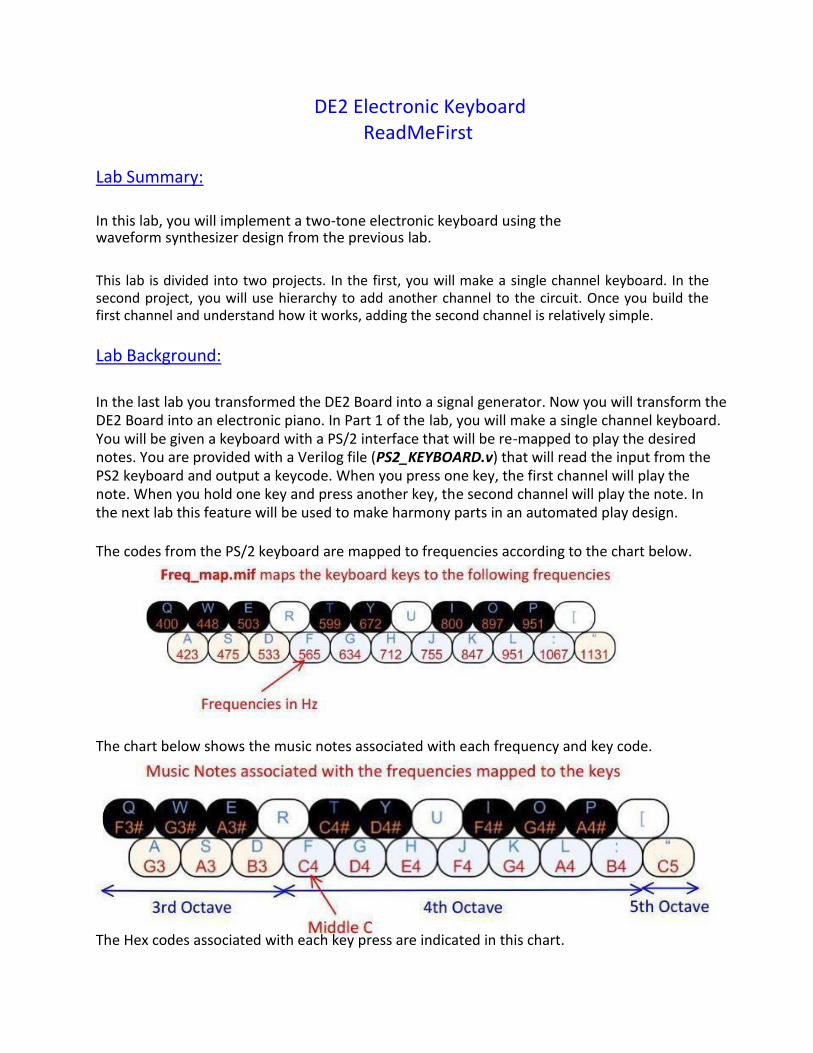
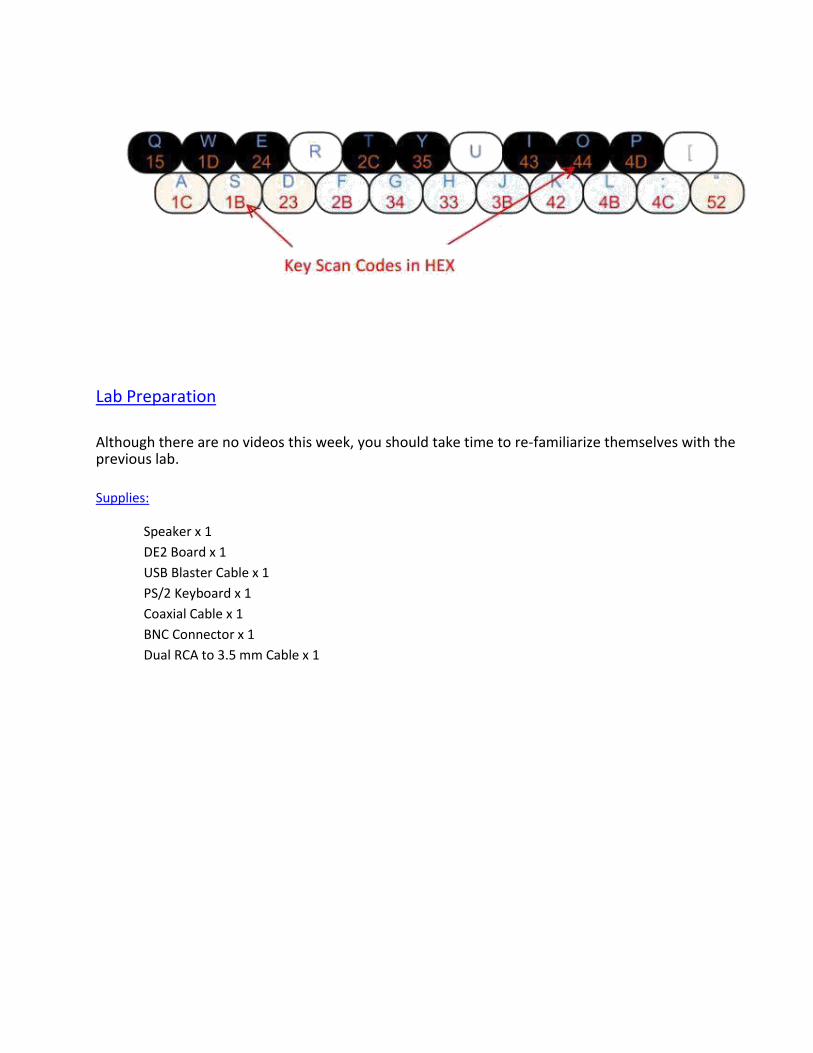
The codes from the PS/2 keyboard are mapped to frequencies according to the chart below. The chart below shows the music notes associated with each frequency and key code.
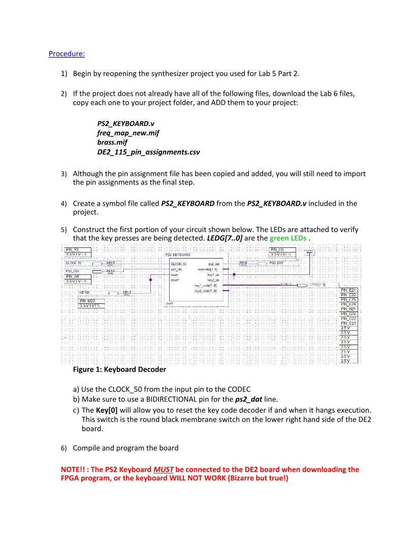
The Hex codes associated with each key press are indicated in this chart.
Lab Preparation
Although there are no videos this week, you should take time to re-familiarize themselves with the previous lab.
Supplies:
Speaker x 1
DE2 Board x 1
USB Blaster Cable x 1
PS/2 Keyboard x 1
Coaxial Cable x 1
BNC Connector x 1
Dual RCA to 3.5 mm Cable x 1

Part 1: Single Channel Electronic Keyboard
The single channel keyboard is based on the synthesizer with 32-bit P values. The CODEC will be used to output the wave to the speaker. Use switch 0 (SW[0]) on the DE2 board to turn the channel on and off. Use the PS/2 keyboard to play notes. The necessary connections are illustrated below
Procedure:
1) Begin by reopening the synthesizer project you used for Lab 5 Part 2.
2) If the project does not already have all of the following files, download the Lab 6 files,
copy each one to your project folder, and ADD them to your project:
PS2_KEYBOARD.v
freq_map_new.mif brass.mif
DE2_115_pin_assignments.csv
3) Although the pin assignment file has been copied and added, you will still need to import the pin assignments as the final step.
4) Create a symbol file called PS2_KEYBOARD from the PS2_KEYBOARD.v included in the
project.
5) Construct the first portion of your circuit shown below. The LEDs are attached to verify that the key presses are being detected. LEDG[7..0] are the green LEDs .
Figure 1: Keyboard Decoder
a) Use the CLOCK_50 from the input pin to the CODEC b) Make sure to use a BIDIRECTIONAL pin for the ps2_dat line. c) The Key[0] will allow you to reset the key code decoder if and when it hangs execution.
This switch is the round black membrane switch on the lower right hand side of the DE2 board.
6) Compile and program the board
NOTE!! : The PS2 Keyboard MUST be connected to the DE2 board when downloading the FPGA program, or the keyboard WILL NOT WORK (Bizarre but true!)
Checkpoint 1: Demonstrate your keyboard decoder to the lab monitor. The LEDs should read 11110000 when no key is pressed, and change when the key codes are sent.
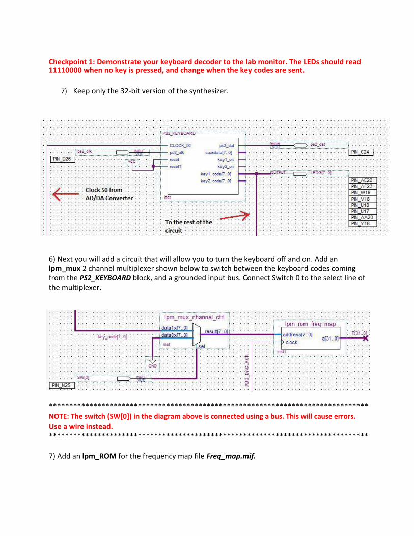
7) Keep only the 32-bit version of the synthesizer.
6) Next you will add a circuit that will allow you to turn the keyboard off and on. Add an lpm_mux 2 channel multiplexer shown below to switch between the keyboard codes coming from the PS2_KEYBOARD block, and a grounded input bus. Connect Switch 0 to the select line of the multiplexer.
******************************************************************************* NOTE: The switch (SW[0]) in the diagram above is connected using a bus. This will cause errors.
Use a wire instead. *******************************************************************************
7) Add an lpm_ROM for the frequency map file Freq_map.mif.
The output of the lpm_ROM containing the Freq_map.mif will replace lpm_constant module in the Synthesizer block. The keyboard codes are used as an address input to the lpm_ROM which replaces the to P values. The ROM contains values for the correct frequencies of the musical tones. The frequencies have already been converted to P values inside the ROM look-up-table for you, so the sampling frequency and width of the data is already taken into account. You are provided the file Freq_map.mif file for this ROM in the Lab 6 file folder. Freq_map.mif has 2^8 words and a width of 32 data bits. Remember to enable the Memory Editor for the lpm_ROM. This will come in handy if you have to troubleshoot the project.
******************************************************************************* NOTE: Giving your lpm modules meaningful names also helps you remember their function. It is also helpful to label buses and wires using functional names. Remember to NOT create components in separate directories. This will usually result in errors that very difficult to resolve and often result in redoing large portions, if not all, of your project. *******************************************************************************
8) Now connect the output of the lpm_ROM containing the Freq_map.mif to the input of the lpm_add_sub of your 32-bit synthesizer circuit from last week. Obviously, you can delete the P value lpm_constant.
9) Replace the sine wave .mif file in the synthesizer from last week with the brass.mif file provided for this lab. This waveform gives a more musical quality to the tone.
Once you have everything connected, you should have the following path in your schematic:
PS2_KEYBOARD block -> Channel Ctrl Multiplexer -> Freq Map Lookup Table -> Synthesizer (brass.mif) -> adc2dac block -> Line Out
************************************************************************ NOTE: A bug in your design can be identified by connecting the LED array to different bus lines in this path to verify that the data is changing whenever a key is pressed. Generally, a bad module will cause everything “downstream” to malfunction. This technique should help you narrow down the location of the error.
************************************************************************
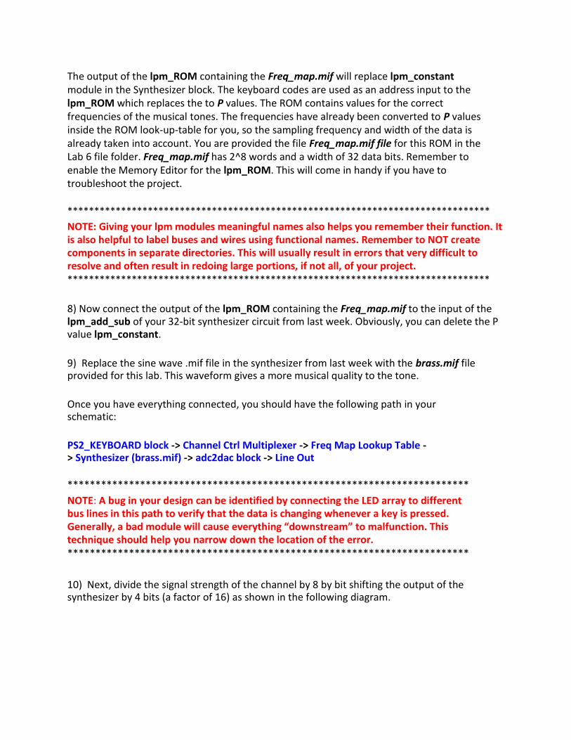
10) Next, divide the signal strength of the channel by 8 by bit shifting the output of the synthesizer by 4 bits (a factor of 16) as shown in the following diagram.
******************************************************************************** NOTE: PLEASE perform the bit shifting to reduce your volume (you will overdrive the speakers and possibly damage them otherwise). I also think my ears are bleeding if you don't do this. ********************************************************************************
12) If you haven't already, connect the provided keyboard to the PS/2 port Do this BEFORE Compiling and Programming the board. You may connect the speaker to the Line Out audio port, but LEAVE IT OFF.
13) Compile and program your design onto the DE2.
14) Turn on the speaker. If you get a horrible screech, your software is not working. Please
turn off your speaker. Otherwise . . .
15) Set SW[0] up to activate 'Keyboard Mode'. Pressing keys on the keyboard should now
generate different notes (Refer to the keyboard layout in the Background section).
Checkpoint 2: Demonstrate your working Single-Channel Keyboard Synthesizer to the lab monitor.
Part 2: Dual-Channel Keyboard
Now, you will add a second channel to your circuit. This allows you to play two keys simultaneously and generate harmony. Rather than rebuilding an entire channel, use hierarchy in your design.
NOTE! ! ! : Make a copy of your working project or an archive before continuing. This is where things often go irreversibly wrong, and you DEFINATELY want the working single channel design to go back to and try again.
Procedure:
1) Copy everything between the PS/2 block and the CODEC (DE2_i2Sound) block into a new schematic sheet and name it Channel. You can delete the LED output pins.
2) Create and connect off page pins for all signals that enter or exit the Channel schematic. Add input pins for the key_code[7..0], the switch (SW[0]), and AUD_DACLRCK and output pins for the synthesizer (wave[15..0]).
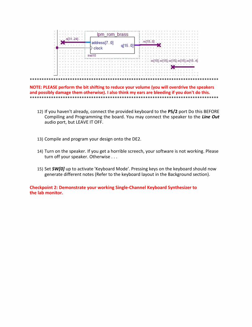
3) With the Channel diagram open, create a symbol block by selecting File->Create/Update-> Create Symbol File for Current File. Substitute the created block in your top level schematic as shown below.
Figure 4: Single Channel Synthesizer with Hierarchy
Checkpoint 3: Demonstrate that your Single-Channel Keyboard Synthesizer STILL works after substituting the Channel block.
4) Conduct the following steps to create a second synthesizer channel. You will have to
replace the lpm_roms in the second channel. If you follow these steps you will only have to do it once. If you perform these steps incorrectly, this process can become an endless loop of frustration and misery! :
a. Save the Channel.bdf schematic as another schematic called Channel2.bdf
b. Replace the frequency map rom (lpm_rom0) with a new lpm_rom. Verify that
Quartus has assigned in incremental name (lpm_rom2, e.g.). Add the same freq_map_new.mif file to the rom.
c. Replace the rom containing the brass.mif file (lpm_rom1) with a new rom,
lpm_rom3 and configure it with the same parameters and brass.mif file.
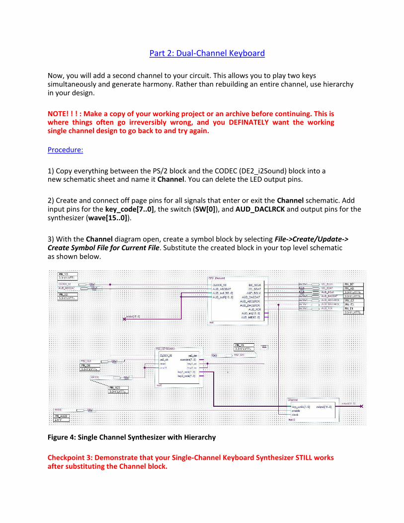
d. Verify that your Channel2.bdf file looks like the following schematic before
creating the block:
Figure 5: Channel2 Schematic used to Generate a Block Symbol
e. Now create a symbol called Channel2 from the modified Channel2.bdf schematic
5) Add a second block for your second channel by inserting the Channel2 symbol in the top level (CODEC) schematic. (makes sense, right?).
6) Connect the Channel2 key_code[7..0] to key2_code[7..0] on the PS2_KEYBOARD block. You can use the red LEDs with an output pin named LEDR[7..0] to verify the channel 2 key codes are working independently.
7) Connect the signal AUD_DACLRCLK to clock input, NOT clock_50.
8) Use SW[1] to enable in order to enable / disable the output of your second channel. If
you use SW[0], you cannot turn the channels off and on independently.
9) Next you need to sum the outputs of the two channels together. In order to preserve the volume, you would normally divide each channel by 2 before adding them together. Since you already bit shifted to reduce the volume, this was already taken into account.
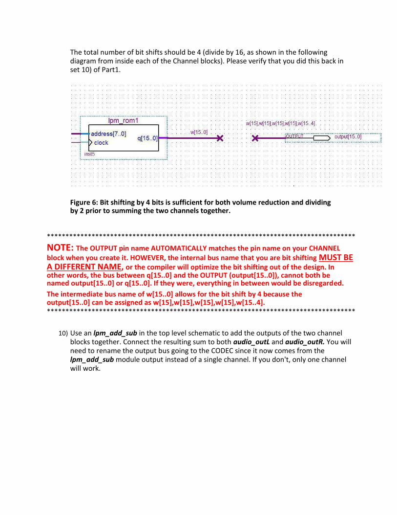
The total number of bit shifts should be 4 (divide by 16, as shown in the following diagram from inside each of the Channel blocks). Please verify that you did this back in set 10) of Part1.
Figure 6: Bit shifting by 4 bits is sufficient for both volume reduction and dividing by 2 prior to summing the two channels together.
***********************************************************************************
NOTE: The OUTPUT pin name AUTOMATICALLY matches the pin name on your CHANNEL block when you create it. HOWEVER, the internal bus name that you are bit shifting MUST BE A DIFFERENT NAME, or the compiler will optimize the bit shifting out of the design. In other words, the bus between q[15..0] and the OUTPUT (output[15..0]), cannot both be named output[15..0] or q[15..0]. If they were, everything in between would be disregarded. The intermediate bus name of w[15..0] allows for the bit shift by 4 because the output[15..0] can be assigned as w[15],w[15],w[15],w[15],w[15..4]. ***********************************************************************************
10) Use an lpm_add_sub in the top level schematic to add the outputs of the two channel blocks together. Connect the resulting sum to both audio_outL and audio_outR. You will need to rename the output bus going to the CODEC since it now comes from the lpm_add_sub module output instead of a single channel. If you don't, only one channel will work.
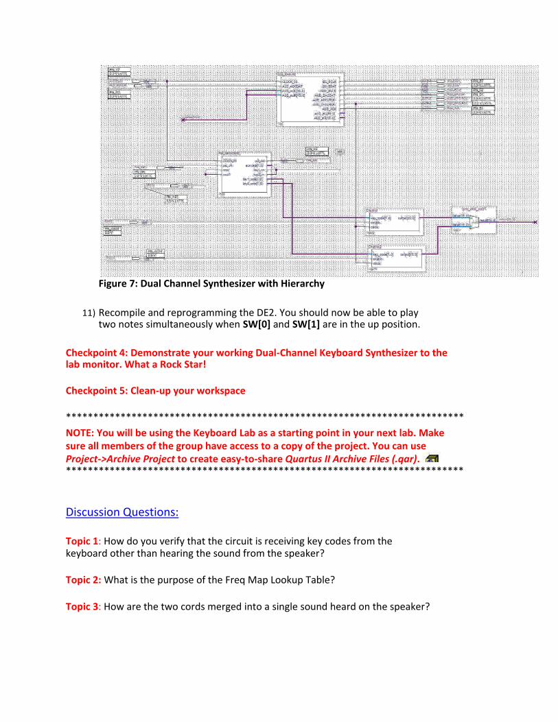
Figure 7: Dual Channel Synthesizer with Hierarchy
11) Recompile and reprogramming the DE2. You should now be able to play two notes simultaneously when SW[0] and SW[1] are in the up position.
Checkpoint 4: Demonstrate your working Dual-Channel Keyboard Synthesizer to the lab monitor. What a Rock Star!
Checkpoint 5: Clean-up your workspace
*************************************************************************
NOTE: You will be using the Keyboard Lab as a starting point in your next lab. Make sure all members of the group have access to a copy of the project. You can use Project->Archive Project to create easy-to-share Quartus II Archive Files (.qar).
*************************************************************************
Discussion Questions:
Topic 1: How do you verify that the circuit is receiving key codes from the keyboard other than hearing the sound from the speaker?
Topic 2: What is the purpose of the Freq Map Lookup Table?
Topic 3: How are the two cords merged into a single sound heard on the speaker?