dda disk drive alalyzer reference manual - triggers and...
TRANSCRIPT

DDA-REF-E Rev C ISSUED: December 1999 ���
� ����������������� ������
������������
Selecting “Edge” and its menus (Fig. 9–1) causes the DDAto trigger whenever the selected signal source meets thetrigger conditions. The trigger source is defined by thetrigger level, coupling, slope or hold-off. Certain of thesebasic conditions applicable for SMART Trigger types arealso selected in “Edge”.
The symbol above is that of an edge trigger with positive slope —the highlighted edge — defined as the trigger condition.
Figure 9–1. Edge Trigger Menus.
Edge
Trigger on
Coupling
Slope Pos|Neg|Window
DC|AC|LFREJ|HFREJ|HF
1|2|3|4|Ext|Ext5 |Line
Holdoff Off|Time|Events

��� ISSUED: December 1999 DDA-REF-E Rev C
����������������� ������
�������������� The trigger source may be:
� The acquisition channel signal (CH 1, CH 2, CH 3 or CH 4)conditioned for the overall voltage gain, coupling, andbandwidth.
� The line voltage that powers the DDA (LINE). This can beused to provide a stable display of signals synchronous withthe power line. Coupling and level are not relevant for thisselection.
� The signal applied to the EXT BNC connector (EXT). Thiscan be used to trigger the DDA within a range of ± 1.2 V onEXT and ± 6 V with EXT/5 as the trigger source.
����� Level defines the source voltage at which the trigger circuit willgenerate an event (a change in the input signal that satisfies thetrigger conditions). The selected trigger level is associated withthe chosen trigger source. Note that the trigger level is specifiedin volts and normally remains unchanged when the vertical gainor offset is modified.
The Amplitude and Range of the trigger level are limited asfollows:
� ± 5 screen divisions with a channel as the trigger source
� ± 1.2 V with EXT as the trigger source
� ± 6 V with EXT/5 as the trigger source
� None with LINE as the trigger source (zero crossing is used).
������� This is the particular type of signal coupling at the input of thetrigger circuit. As with the trigger level, the coupling can beindependently selected for each source. Thus changing thetrigger source can change the coupling. The types of couplingable to be selected are:
� DC: All the signal’s frequency components are coupled to thetrigger circuit for high-frequency bursts or where the use ofAC coupling would shift the effective trigger level.
����� Once specified, Trigger Level and Coupling are theonly parameters that pass unchanged from trigger mode totrigger mode for each trigger source.

DDA-REF-E Rev C ISSUED: December 1999 ���
���
� AC: The signal is capacitively coupled, DC levels are rejectedand frequencies below 10 Hz attenuated.
� LF REJ: The signal is coupled via a capacitive high-passfilter network, DC is rejected and signal frequencies below100 MHz are attenuated. For stable triggering on medium- tohigh-frequency signals.
� HF REJ: Signals are DC-coupled to the trigger circuit and alow-pass filter network attenuates frequencies above 50 kHz.For triggering on low frequencies.
� HF: To be used only when necessary for triggering on high-frequency repetitive signals > 300 MHz, with a maximumtrigger frequency of > 1 GHz. HF is automatically overriddenand set to AC when incompatible with other triggercharacteristics (and SMART Trigger types). Only one slopeavailable.
����� Slope determines the direction of the trigger voltage transitionused for generating a particular trigger event. Like coupling, theselected slope is associated with the chosen trigger source.
��������� Without hold-off, the time between each successive trigger eventwould be limited only by the input signal, the coupling, and theDDA’s bandwidth.
However, sometimes a stable display of complex repetitivewaveforms can be achieved by placing a condition on this time.This is a hold-off, which can be expressed either as a period oftime or an event count. Hold-off disables the trigger circuit for agiven period of time or events (an event is the number ofoccasions on which the trigger condition is met) after the lasttrigger occurred. The trigger will again occur when the hold-offhas elapsed and the other specified conditions are met. Hold-offis used to obtain a stable trigger for repetitive, compositewaveforms. For example, if the number or duration of sub-signalsis known they can be disabled by choosing an appropriate hold-off value.
��� ISSUED: December 1999 DDA-REF-E Rev C
����������������� ������
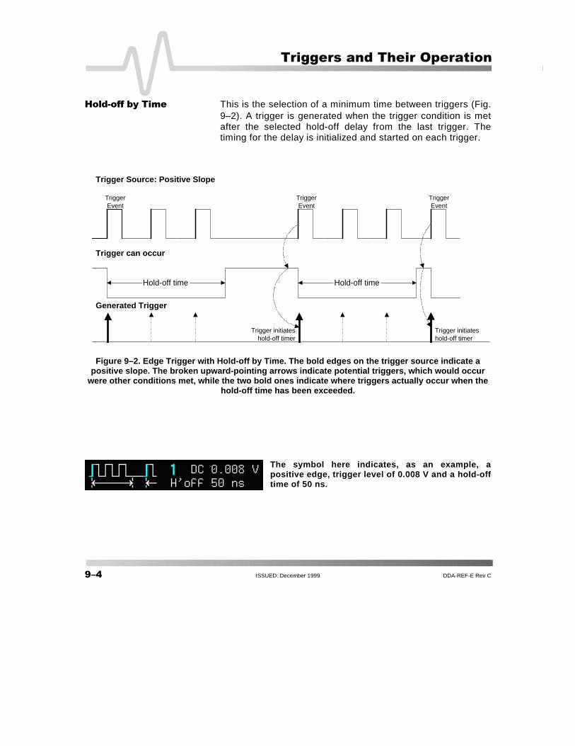
�������������� � This is the selection of a minimum time between triggers (Fig.9–2). A trigger is generated when the trigger condition is metafter the selected hold-off delay from the last trigger. Thetiming for the delay is initialized and started on each trigger.
Figure 9–2. Edge Trigger with Hold-off by Time. The bold edges on the trigger source indicate apositive slope. The broken upward-pointing arrows indicate potential triggers, which would occur
were other conditions met, while the two bold ones indicate where triggers actually occur when thehold-off time has been exceeded.
The symbol here indicates, as an example, apositive edge, trigger level of 0.008 V and a hold-offtime of 50 ns.
Hold-off time Hold-off time
Trigger Source: Positive Slope
Trigger can occur
Generated Trigger
TriggerEvent
TriggerEvent
TriggerEvent
Trigger initiateshold-off timer
Trigger initiateshold-off timer

DDA-REF-E Rev C ISSUED: December 1999 ���
���
����������������� Hold-off by events is initialized and started on each trigger(Fig. 9–3). A trigger is generated when the trigger condition is metafter the selected number of events from the last trigger. An event isdefined as the number of times the trigger condition is met after thelast trigger. For example, if the number selected is two, as it is inFigure 9–3, the trigger will occur on the third event. From 1 to99 999 999 events can be selected.
Figure 9–3. Edge Trigger with Hold-off by Events (in this example, by two events). The bold edgeson the trigger source indicate a positive slope. The broken, upward-pointing arrows indicate
potential triggers, while the bold ones show where triggers actually occur after the hold-off expires.
The symbol indicates a hold-off of 37 events.
Hold-off by 2 events Hold-off by 2 events
Trigger Source: Positive Slope
Trigger can occur
Generated Trigger
Event#1
Event#2
Event#2
Event#1
TriggerEvent
TriggerEvent
TriggerEvent
Trigger initiateshold-off timer
Triggerinitiateshold-offtimer

��� ISSUED: December 1999 DDA-REF-E Rev C
����������������� ������
The Window Trigger (Fig. 9–4) allows the definition of awindow region whose boundaries extend above and below theselected trigger level. A trigger event occurs when the signalleaves this window region in either direction and passes into theupper or lower region. The next trigger will occur if and when thesignal again passes into the window region. For a trigger tooccur, the time that the signal spends within the window must beat least 0.5 ns.
Figure 9–4. Edge Window Trigger: trigger when the signal leaves the window region.
The symbol indicates the trigger level and the range of the window region.
!���"��������W
IND
OW
RE
GIO
N
Trigger Level
Triggers
Time
Lower Region
Upper Region

DDA-REF-E Rev C ISSUED: December 1999 ���
���
�#�$���������
SMART Trigger allows the setting of additional qualificationsbefore a trigger is generated. Types include triggers adapted forglitches, intervals, abnormal signals, TV signals, state- or edge-qualified events, dropouts, patterns, “runts” and slew rate.
%������������� Generally speaking a glitch is a pulse much faster than the observedwaveform. Glitch Trigger (Fig. 9–5) is used to capture narrow pulsesless than or equal to, or greater than or equal to, a given time limit.
The symbol above indicates, as an example, a pulse width of 10 ns.
Figure 9–5. Glitch Trigger Menus.
Glitch
Trigger on
Coupling
At end ofNeg|Pos
pulse
DC|AC|LFREJ|HFREJ
1|2|3|4|Ext|Ext5
Width: lessthan or equal
toOff|Time
Width:greater thanor equal to
Off|Time

�� ISSUED: December 1999 DDA-REF-E Rev C
����������������� ������
GlitchWidth
Generated Trigger
GlitchWidth
WidthSelected
Trigger Source
Trigger can occur
WidthSelected
%���������������� Digital electronics circuits normally use an internal clock, and fortesting purposes a glitch can be defined as any pulse of widthsmaller than the clock- or half-period. Glitch Trigger has a broadrange of applications in digital and analog electronic development,ATE, EMI, telecommunications, and magnetic media studies.
This Glitch Trigger selects a maximum pulse width (Fig. 9–6). Itis generated on the selected edge when the pulse width is lessthan or equal to the selected width. The timing for the width isinitialized and restarted on the opposite slope to that selected.Glitches as short as 600 ps can be triggered on, and widths of600 ps–20 s selected. On the other models, widths of between2.5 ns and 20 s can be selected, but typically triggering will occuron glitches 1 ns wide.
Figure 9–6. Glitch Trigger: here on a pulse width less than or equalto the width selected. The broken upward arrow indicates a
potential trigger, while the bold one shows where the actual triggeroccurs.
&������ ����������������&�����!����

DDA-REF-E Rev C ISSUED: December 1999 ��
���
�'�������������� Selecting “Glitch” and setting width conditions can also enablethe exclusion of events that either fall within, or outside of, aselected width range. This is an exclusion trigger (Fig. 9–7).When it is decided to exclude from triggering all those eventswithin a particular range, only pulses outside — less-than-or-equal-to or greater-than-or-equal-to — this range will generate atrigger event. Alternatively, it may be decided to trigger only onthose pulses in the range itself and exclude all those outside it.The timing for the width is initialized and restarted on the slopeopposite to the selected edge. Widths of the same values as forGlitch Trigger can be selected (see previous page).
Figure 9–7. Exclusion Trigger. In this example, only pulses outsidethe boundaries of the width range, those of ≤ 25.0 ns or ≥ 27.5 nsin length, will be captured. Note the “OR” in the “width ≥” menu,which changes to “&” when triggering only within the range.
�'����������������� Exclusion Triggers allow a signal’s normal width or period to bespecified, with the DDFA instructed to ignore the normallyshaped signals and trigger only on abnormal ones. Circuitfailures, for instance, can be looked for all the time.

���� ISSUED: December 1999 DDA-REF-E Rev C
����������������� ������
(������������� Whereas Glitch Trigger performs over the width of a pulse,Interval Trigger (Fig. 9–8) performs over the width of an interval.An interval corresponds to a the signal duration (the period)separating two consecutive edges of the same polarity: positiveto positive edge; negative to negative edge. Interval Trigger isused to capture intervals that are inferior to or exceeding a given timelimit. In addition, a width range can be defined to capture any intervalthat is comprised within or outside the specified range — anExclusion Trigger by Interval.
Figure 9–8. Interval Trigger Menus.
(���������������� Interval Trigger is helpful for determining missing cycles ortransitions, and for ignoring unwanted signal reflections.
Interval
Trigger on
Coupling
BetweenNeg|Pos
edges
DC|AC|LFREJ|HFREJ
1|2|3|4|Ext|Ext5
Interval:less than or
equal toOff|Time
Interval:greater thanor equal to
Off|Time

DDA-REF-E Rev C ISSUED: December 1999 ����
���
(������� ���� For this Interval Trigger, generated on a time interval smaller than theone selected, a maximum interval between two like edges of thesame slope — positive, for example — is chosen (Fig. 9–9). Thetrigger is generated on the second (positive) edge if it occurs withinthe selected interval. The timing for the interval is initialized andrestarted whenever the selected edge occurs. Intervals of between2 ns and 20 s can be selected.
Figure 9–9. Interval Trigger that triggers when the interval width issmaller than the selected interval. The broken, upward-pointing
arrow indicates a potential trigger, while the bold one showswhere the actual trigger occurs — on the positive edge within the
selected interval.
The symbol indicates a positive slopeand interval of ≤ 1.99 ms selected.
Generated Trigger
SelectedInterval
Trigger Source: Positive Slope
Trigger can occur
SelectedInterval
Interval WidthIntervalWidth

���� ISSUED: December 1999 DDA-REF-E Rev C
����������������� ������
(����������� For this Interval Trigger, generated on an interval larger than theone selected, a minimum interval between two edges of thesame slope is selected (Fig. 9–10). The trigger is generated onthe second edge if it occurs after the selected interval. The timingfor the interval is initialized and restarted whenever the selectededge occurs. Intervals of between 2 ns and 20 s can be selected.
Figure 9–10. Interval Trigger that triggers when the interval widthis larger than the selected interval. The broken upward-pointing
arrow indicates a potential trigger, while the bold one showswhere the actual trigger occurs — on the positive edge after the
selected interval.
The symbol indicates a positive slope and interval of ≥258 ns selected.
Interval Width
Generated Trigger
SelectedInterval
Trigger Source: Positive Slope
Trigger can occur
SelectedInterval
IntervalWidth
DDA-REF-E Rev C ISSUED: December 1999 ����
���
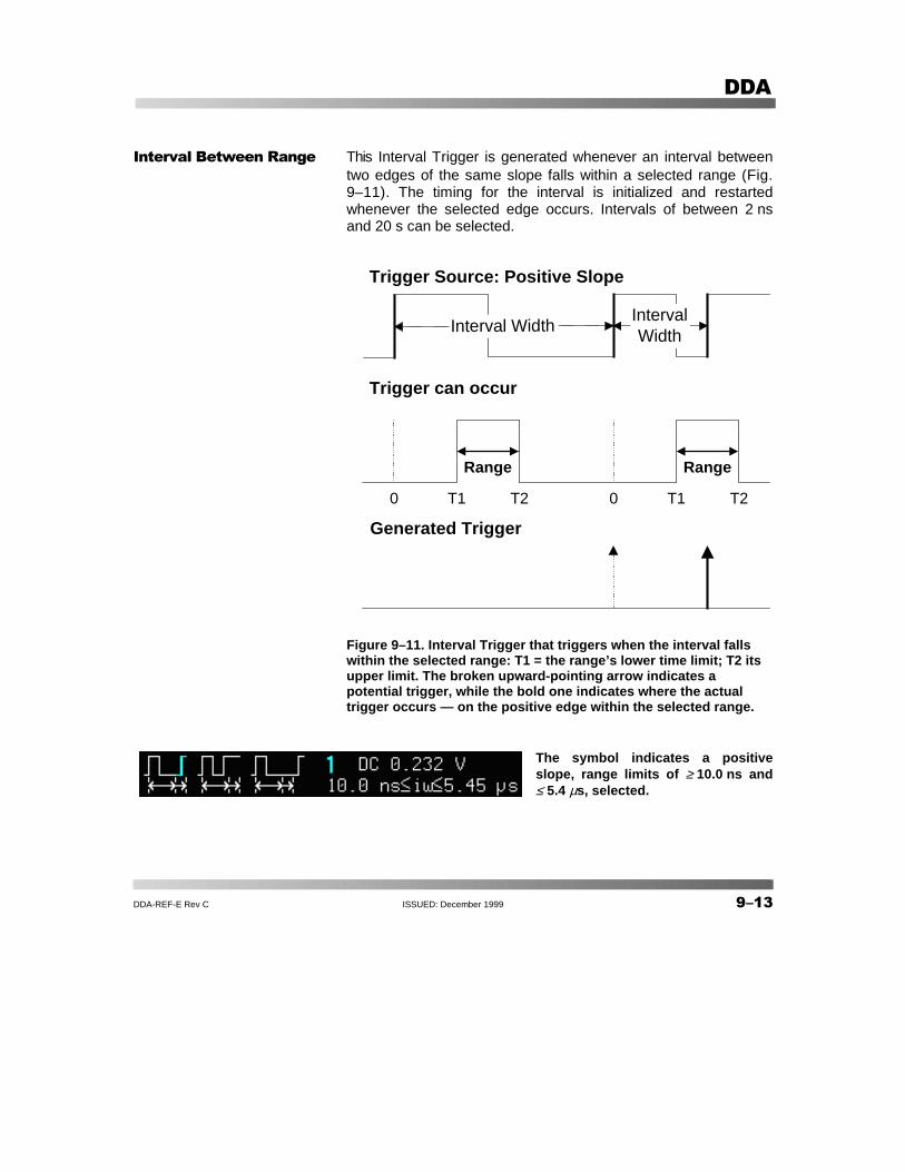
(������)��"���$�� This Interval Trigger is generated whenever an interval betweentwo edges of the same slope falls within a selected range (Fig.9–11). The timing for the interval is initialized and restartedwhenever the selected edge occurs. Intervals of between 2 nsand 20 s can be selected.
Figure 9–11. Interval Trigger that triggers when the interval fallswithin the selected range: T1 = the range’s lower time limit; T2 itsupper limit. The broken upward-pointing arrow indicates apotential trigger, while the bold one indicates where the actualtrigger occurs — on the positive edge within the selected range.
The symbol indicates a positiveslope, range limits of ≥ 10.0 ns and≤ 5.4 µs, selected.
Interval Width
Generated Trigger
Trigger can occur
Trigger Source: Positive Slope
0 0T1 T1T2 T2
RangeRange
IntervalWidth

���� ISSUED: December 1999 DDA-REF-E Rev C
����������������� ������
(������ �������$�� This Interval Trigger is generated whenever an interval betweentwo edges of the same slope falls outside a selected range (Fig.9–12). The trigger is generated on the second edge if it occursafter the selected interval range. The timing for the interval isinitialized and restarted whenever the selected edge occurs.Intervals of between 2 ns and 20 s can be selected.
Figure 9–12. Interval Trigger that triggers when the interval fallsoutside the selected range: T1 = the range’s lower time limit; T2 its
upper limit. The broken upward-pointing arrow indicates apotential trigger, while the bold one shows where the actual trigger
occurs, on the positive edge outside the selected range.
The symbol indicates a positive slope, andrange limits of ≤ 10.0 ns and ≥347.5 nsselected. “OR” means that intervals aboveor below the range have been targeted.
Interval Width
Generated Trigger
Trigger can occur
Trigger Source: Positive Slope
0 0T1 T1T2 T2
RangeRange
IntervalWidth

DDA-REF-E Rev C ISSUED: December 1999 ����
���
&������������ Pattern Trigger (Fig. 9–13) enables triggering on a logicalcombination of the five inputs CH 1, CH 2, CH 3, CH 4 and EXT.This combination, called a pattern, is defined as the logical AND oftrigger states. A trigger state is either high or low: high when a triggersource is greater than the trigger level, or threshold, and low whenless than it (Fig. 9–14). For example, a pattern could be defined aspresent when the trigger state for CH 1 is high, CH 2 is low, and EXTis irrelevant (X or don’t care). If any of these conditions are not met,the pattern state is considered absent. Hold-off limits from 2 ns–20 s, or from 1 to 99 999 999 events, can be selected.
Figure 9–13. Pattern Trigger Menus.
Pattern
Trigger on
Patternwith
Coupling DC|AC|LFREJ|HFREJ
1|2|3|4|Ext
Exiting| Entering
Level L|H|X|(Level value)
Off|Time|EvtsHoldoff
���� ISSUED: December 1999 DDA-REF-E Rev C
����������������� ������
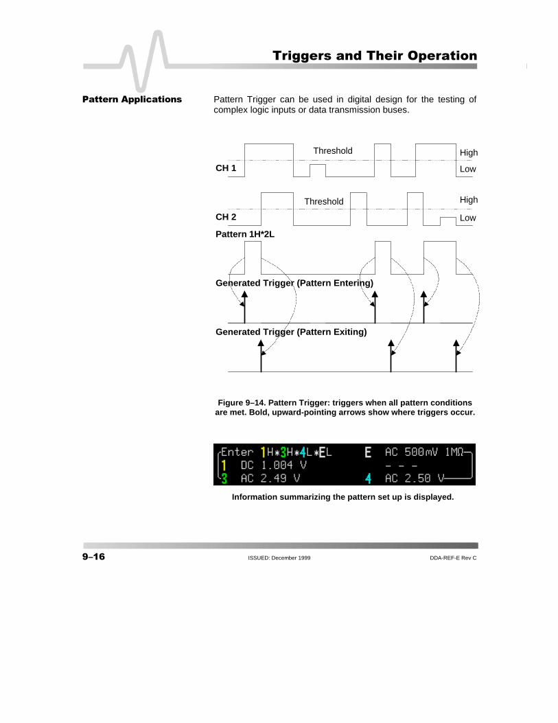
&��������������� Pattern Trigger can be used in digital design for the testing ofcomplex logic inputs or data transmission buses.
Figure 9–14. Pattern Trigger: triggers when all pattern conditionsare met. Bold, upward-pointing arrows show where triggers occur.
Information summarizing the pattern set up is displayed.
CH 1
Generated Trigger (Pattern Entering)
Pattern 1H*2L
Threshold
CH 2
Generated Trigger (Pattern Exiting)
Threshold
High
High
Low
Low
DDA-REF-E Rev C ISSUED: December 1999 ����
���
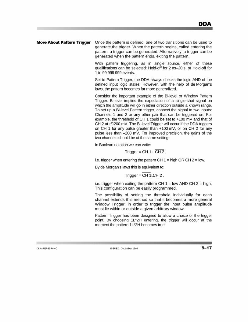
#����������&������������ Once the pattern is defined, one of two transitions can be used togenerate the trigger. When the pattern begins, called entering thepattern, a trigger can be generated. Alternatively, a trigger can begenerated when the pattern ends, exiting the pattern.
With pattern triggering, as in single source, either of thesequalifications can be selected: Hold-off for 2 ns–20 s, or Hold-off for1 to 99 999 999 events.
Set to Pattern Trigger, the DDA always checks the logic AND of thedefined input logic states. However, with the help of de Morgan'slaws, the pattern becomes far more generalized.
Consider the important example of the Bi-level or Window PatternTrigger. Bi-level implies the expectation of a single-shot signal onwhich the amplitude will go in either direction outside a known range.To set up a Bi-level Pattern trigger, connect the signal to two inputs:Channels 1 and 2 or any other pair that can be triggered on. Forexample, the threshold of CH 1 could be set to +100 mV and that ofCH 2 at �200 mV. The Bi-level Trigger will occur if the DDA triggerson CH 1 for any pulse greater than +100 mV, or on CH 2 for anypulse less than –200 mV. For improved precision, the gains of thetwo channels should be at the same setting.
In Boolean notation we can write:
Trigger CH 1 CH 2= + ,
i.e. trigger when entering the pattern CH 1 = high OR CH 2 = low.
By de Morgan's laws this is equivalent to:
Trigger CH 1 CH 2= ⋅ ,
i.e. trigger when exiting the pattern CH 1 = low AND CH 2 = high.This configuration can be easily programmed.
The possibility of setting the threshold individually for eachchannel extends this method so that it becomes a more generalWindow Trigger: in order to trigger the input pulse amplitudemust lie within or outside a given arbitrary window.
Pattern Trigger has been designed to allow a choice of the triggerpoint. By choosing 1L*2H entering, the trigger will occur at themoment the pattern 1L*2H becomes true.

��� ISSUED: December 1999 DDA-REF-E Rev C
����������������� ������
*���������������� In the case of Qualified Triggers (Fig. 9–15), a signal’s transitionabove or below a given level — its validation — serves as anenabling, or qualifying, condition for a second signal that is thesource of the trigger.
Two Qualified Triggers are available: State-Qualified, where theamplitude of the first signal must remain in the desired state untilthe trigger occurs, and Edge-Qualified, for which the validation issufficient and no additional requirement is placed on the firstsignal (for the separate, Qualified First Trigger, see page 9–1).
A Qualified Trigger can occur immediately after the validation orwithin a set time after it. Or it can occur following apredetermined time delay or number of potential trigger events.The time delay or trigger count is restarted with every validation.
Figure 9–15. State- and Edge-Qualified Trigger Menus.
Qualified
By
Trigger on
After
Edge|State qualifier
Has goneAbove|Below
value
WithinWait
Off|Time <| Time> | Evts
1|2|3|4|Ext|Ext5
1|2|3|4|Ext|Ext5
Qualified
By
Trigger on
Only after 1|2|3|4|Ext|Ext5
1|2|3|4|Ext|Ext5
Edge|State qualifier
Goes andstays
Above|Belowvalue
Off|Time <| Time> | EvtsWithinWait

DDA-REF-E Rev C ISSUED: December 1999 ���
���
Qualified Triggers offer the choice of generating a trigger eitherwhen a selected pattern is present or absent. As with PatternTrigger, the pattern is defined as a logical AND combination oftrigger states that are either high or low: high when a triggersource is greater than the selected trigger level, and low when itis less than. For example, a pattern might be defined as presentwhen the trigger states for Channels 1 and 2 are high and EXT islow. If any of these conditions is not met, the pattern state isconsidered absent.
Qualified Triggers allow an additional qualification once theselected pattern state occurs. For example: “wait for 10 ns up to20 s, trigger on CH 1 to the 99 999 999th event”. The pattern isused to qualify the trigger without actually generating it.Triggering will occur when another signal, the trigger source,meets its trigger condition while the pattern is present. Thetrigger source itself is not allowed in the pattern.
*������������������ Typical applications can be found wherever time violations occur,such as in micro-processor debugging or telecommunications.
�����*��������"����!�� State-Qualified Trigger with Wait (Fig. 9–16) is determined by theparameters of Time or the number of Events:
� Time determines a delay from the start of the desiredpattern. After the delay (timeout) and while the pattern ispresent, a trigger can occur. The timing for the delay isrestarted when the selected pattern begins.
� Events determines a minimum number of events of thetrigger source. An event is generated when a trigger sourcemeets its trigger conditions. On the selected event of thetrigger source and while the pattern is present, a trigger canoccur. The count is initialized and started whenever theselected pattern begins, and continues while the patternremains. When the selected count is reached, the triggeroccurs.
This symbol is that for a State-Qualified-with-time-Wait trigger: positive slope, 2 ns delay,“goes and stays Above” �24 mV.

���� ISSUED: December 1999 DDA-REF-E Rev C
����������������� ������
Figure 9–16. State-Qualified by Wait: Trigger after timeout. The broken upward-pointing arrowsindicate potential triggers, while the bold arrows show where the actual triggers occurs.
As the above figure illustrates, a trigger is generated on a risingedge whenever the pattern is asserted (pattern present) and thewait timeout has expired. The timeout is, respectively, activatedor disabled once the pattern is asserted or absent.
The symbol shown here is that of an Edge-Qualified-with-event Waittrigger on CH 2 (described next page): positive slope, wait of 109
events, level of 2.50 V, and pattern present as indicated.
Generated Trigger
Wait
Trigger Source: Positive Slope
Trigger can occur
Qualifier: Pattern Present
Wait

DDA-REF-E Rev C ISSUED: December 1999 ����
���
�����*��������"����!�� Like its State-Qualified equivalent, Edge-Qualified with Wait(Fig. 9–17) is conditioned by either Time or Events:
� Time determines a delay from the start of the desiredpattern. After the delay (timeout) and before the end of thepattern, a trigger can occur. The timing for the delay isrestarted when the selected pattern begins.
� Events determines a minimum number of events for thetrigger source. An event is generated when a trigger sourcemeets its trigger conditions. A trigger can occur on theselected event of the trigger source and before the end of thepattern. The count is initialized and started whenever theselected pattern begins. It continues while the patternremains. When the selected count is reached, the triggeroccurs.
Figure 9–17. Edge-Qualified by Wait: Trigger after timeout. The brokenupward-pointing arrows indicate potential triggers, while the bold
ones show where the actual trigger occurs.
SelectedTime
SelectedTime
Trigger Source: Positive Slope
Qualifier: Pattern Present
Trigger can occur
Generated Trigger

���� ISSUED: December 1999 DDA-REF-E Rev C
����������������� ������
Qualified First Trigger (Fig. 9–18) is similar to the QualifiedTriggers and presents exactly the same menus. Qualified First isintended to be used exclusively in Sequence Mode to speed upthe trigger rate. With Qualified First, a single valid trigger issufficient to acquire a full sequence. Other than in SequenceMode, Qualified First is identical to the Qualified Triggers.
Figure 9–18. Qualified First Trigger Menus.
���������� In Data Storage, the index pulse can be defined as the qualifiersignal and the servo gate signal as the trigger source.
Qual First
By
Trigger on
After
Edge|State qualifier
Has goneAbove|Below
value
WithinWait
Off|Time <| Time> | Evts
1|2|3|4|Ext|Ext5
1|2|3|4|Ext|Ext5
*��������+������������

DDA-REF-E Rev C ISSUED: December 1999 ����
���
Figure 9–19. Comparing Qualified (top) and Qualified First (bottom) Triggers. Whereas the (Edge-)Qualified Trigger requires that each of the segments be “qualified” by a valid condition in Sequence
Mode, Qualified First Trigger needs only a single valid condition to qualify a full sequence ofsegments. Note that the inter-segment deadtime (DT) is much shorter with Qualified First, which is
used only in Sequence Mode.
Qualified First Trigger symbol.
DT
Qualifier
Segment 1DT
Trigger
Segment 2 Segment N
DT
Qualifier
Segment 1
Trigger
Segment 2 Segment NDT
(Edge-)Qualified Trigger
Qualified First Trigger

���� ISSUED: December 1999 DDA-REF-E Rev C
����������������� ������
�,�������� A special kind of Edge-Qualified Trigger, TV Trigger (Fig. 9–20)allows stable triggering on standard or user-defined compositevideo signals, on a specific line of a given field. TV Trigger canbe used on PAL, SECAM or NTSC systems.
A composite video signal on the trigger input is analyzed to provide asignal for the beginning of the chosen field — “any”, “odd” or “even”— and for a signal at the beginning of each line. The field signalprovides the starting transition, and the beginnings of line pulses arecounted to allow the final trigger on the chosen line. Each field, thenumber of fields, the field rate, interlace factor, and number of linesper picture must be specified — although there are standard settingsfor the most common types of TV signals. TV Trigger can alsofunction in a simple any-line mode.
Figure 9–20. TV Trigger Menus.
TV
TV signal on
# of fields
TV type Standard | Custom
1|2|4|8
1|2|3|4|Ext|Ext5
as: 625/50/2:1| 525/60/2:1(Standard)
as: Line#|Hz|Interlacing#:#(Custom)
Trigger on Line# | Field# |any
DDA-REF-E Rev C ISSUED: December 1999 ����
���
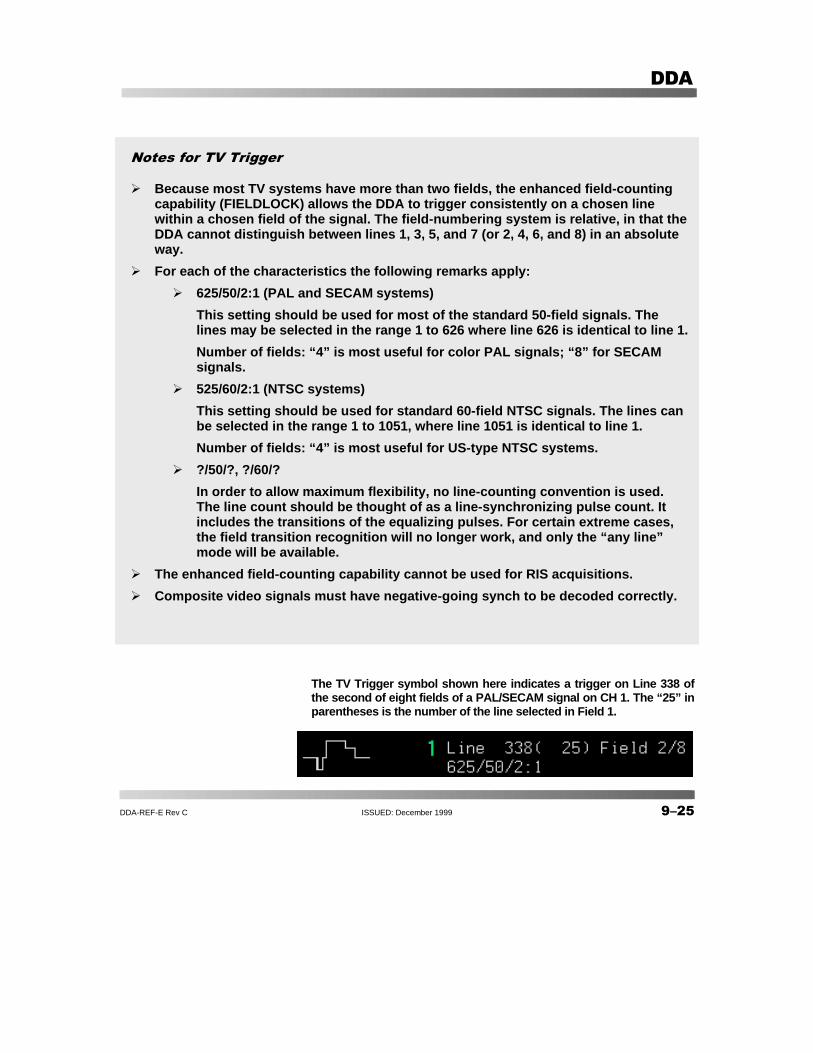
The TV Trigger symbol shown here indicates a trigger on Line 338 ofthe second of eight fields of a PAL/SECAM signal on CH 1. The “25” inparentheses is the number of the line selected in Field 1.
������������ �
� Because most TV systems have more than two fields, the enhanced field-countingcapability (FIELDLOCK) allows the DDA to trigger consistently on a chosen linewithin a chosen field of the signal. The field-numbering system is relative, in that theDDA cannot distinguish between lines 1, 3, 5, and 7 (or 2, 4, 6, and 8) in an absoluteway.
� For each of the characteristics the following remarks apply:
� 625/50/2:1 (PAL and SECAM systems)
This setting should be used for most of the standard 50-field signals. Thelines may be selected in the range 1 to 626 where line 626 is identical to line 1.
Number of fields: “4” is most useful for color PAL signals; “8” for SECAMsignals.
� 525/60/2:1 (NTSC systems)
This setting should be used for standard 60-field NTSC signals. The lines canbe selected in the range 1 to 1051, where line 1051 is identical to line 1.
Number of fields: “4” is most useful for US-type NTSC systems.
� ?/50/?, ?/60/?
In order to allow maximum flexibility, no line-counting convention is used.The line count should be thought of as a line-synchronizing pulse count. Itincludes the transitions of the equalizing pulses. For certain extreme cases,the field transition recognition will no longer work, and only the “any line”mode will be available.
� The enhanced field-counting capability cannot be used for RIS acquisitions.
� Composite video signals must have negative-going synch to be decoded correctly.

���� ISSUED: December 1999 DDA-REF-E Rev C
����������������� ������
��������������� Dropout Trigger (Fig. 9–21) provides triggering whenever thesignal disappears for a set period of time. The trigger isgenerated at the end of the time-out period following the “last”trigger-source transition, as shown in the figure on the next page(Fig. 9–23). Time-outs of between 2 ns and 20 s can be selected.
Figure 9–21. Dropout Trigger Menus.
������������������ Dropout Trigger is useful for detecting interruptions in datastreams such as network hang-ups and microprocessor crashes.A typical application is on the last ‘normal’ interval of a signal thathas disappeared completely. This is essentially a single-shotapplication, usually with a pre-trigger delay. RIS acquisition is notuseful here because the timing of the trigger timeout isinsufficiently correlated to the input channel signals.
Dropout
Trigger aftertimeout if no edge
occurs on
With slope
Within Time
Positive|Negative
1|2|3|4|Ext|Ext5

DDA-REF-E Rev C ISSUED: December 1999 ����
���
Figure 9–22. Dropout Trigger: occurs when the time-out has expired. The bold upward-pointingarrows show where the trigger occurs.
This Dropout Trigger symbol indicates a a waittime-out of 25 ns.
Generated Trigger
Trigger Source
Trigger can occurWait
Time-outWait
Time-out

��� ISSUED: December 1999 DDA-REF-E Rev C
����������������� ������
Runt
Trigger on
Coupling
WithLevel: upper level |
lower level
DC|AC|LFREJ|HFREJ
1|2|3|4|Ext|Ext5
Width: runt <= | runt >=
Edge: Negative | Positive
The Runt Trigger (Fig. 9–23) is programmed to occur when apulse crosses a first threshold line and fails to cross a secondthreshold line before re-crossing the first (Fig. 9–24). Boththresholds are able to be selected within a range of 600 ps–20 s.Other defining conditions for this trigger are the edge (triggers onthe opposite slope to that selected) and the runt width.
Figure 9–23. Runt Trigger Menus.
$������������� Runt Trigger is particularly helpful for detecting meta-stableconditions in digital design.
$����������

DDA-REF-E Rev C ISSUED: December 1999 ���
���
Figure 9–24. Runt Trigger: triggers when a pulse crosses the first threshold but not the second beforere-crossing the first — marked by the bold, upward-pointing arrows.
The symbol indicates a positive edge (“Neg” was selected to obtainthis), the difference between the two threshold levels (“veto”), and the
runt width.
Trigger Source
Generated Trigger (Positive Slope)
Generated Trigger (Negative Slope)
Upper Threshold Level
Lower Threshold Level
���� ISSUED: December 1999 DDA-REF-E Rev C
����������������� ������
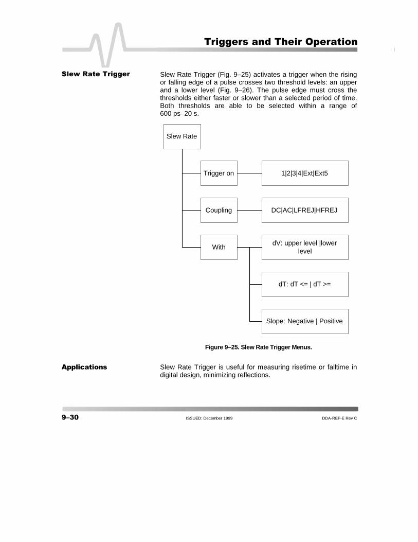
Slew Rate Trigger (Fig. 9–25) activates a trigger when the risingor falling edge of a pulse crosses two threshold levels: an upperand a lower level (Fig. 9–26). The pulse edge must cross thethresholds either faster or slower than a selected period of time.Both thresholds are able to be selected within a range of600 ps–20 s.
Figure 9–25. Slew Rate Trigger Menus.
���������� Slew Rate Trigger is useful for measuring risetime or falltime indigital design, minimizing reflections.
Slew Rate
Trigger on
Coupling
WithdV: upper level |lower
level
DC|AC|LFREJ|HFREJ
1|2|3|4|Ext|Ext5
dT: dT <= | dT >=
Slope: Negative | Positive
���"�$����������

DDA-REF-E Rev C ISSUED: December 1999 ����
���
Figure 9–26. Slew Rate Trigger: occurs when a rising or falling edge crosses two thresholds (dV)outside a selected time range (dT), marked by the bold, upward-pointing arrow.
The Slew Rate symbol is the same as the Edge Trigger symbol,but indicates lower (0.556 V) and upper (188 m) threshold levels,
and a time range — here, � 73.6 mV/ns.
Trigger Source
Generated Trigger
UpperThreshold Level
Lower ThresholdLevel
dT
dV
dT dT dT

���� ISSUED: December 1999 DDA-REF-E Rev C
����������������� ������
�(�-���������
DISK Triggers are the DDA’s drive-specific triggers.
�������&������������ Sector Pulse Trigger (Fig. 9–27) triggers on the specified edge (Pos orNeg) of a specified sector after an Index (Fig. 9–28). The thresholds forIndex and Sector pulse are set to 1.5 V.
Figure 9–27. Sector Pulse Trigger menus.
SectorPulse
Trigger on
Sector Pulse
Index
Polarity: Neg|Pos
1|2|3|4|Ext5
Sector # after Index
1|2|3|4|Ext5
Polarity: Neg|Pos

DDA-REF-E Rev C ISSUED: December 1999 ����
���
Figure 9–28. Servo Gate Trigger: occurs (bold, upward-pointing arrow) on the specified edge (Pos or Neg)of the nth sector.
Generated Trigger
Index
Sector Pulse nth sector after Index

���� ISSUED: December 1999 DDA-REF-E Rev C
����������������� ������
$���%���������� The Read Gate Trigger (Fig. 9–29) triggers on the specified edge(Pos or Neg) of a pulse that is longer than a specified time (Fig.9–30). The minimum pulse width is specified so that the ReadGate Trigger does not trigger on other narrower pulses such asID fields. The thresholds for Read Gate Trigger is set to 1.5 V.
Figure 9–29. Read Gate Trigger Menus.
Read Gate
Read Gate
Read Gate
Width > Time
Polarity: Neg|Pos
1|2|3|4

DDA-REF-E Rev C ISSUED: December 1999 ����
���
Figure 9–30. Read Gate Trigger: occurs (bold, upward-pointing arrow) on the trailing edge of a Read Gatewider than a specified width. The polarity of the Read Gate signal can also be specified.
Generated Trigger
Trigger Source
WidthWidth

���� ISSUED: December 1999 DDA-REF-E Rev C
����������������� ������
������%���������� The Servo Gate Trigger (Fig. 9–31) triggers periodically byskipping a specified number of Servo Gates after each trigger(Fig. 9–32). The initial trigger occurs at the specified Servo Gateafter an Index pulse. The thresholds for Index and Servo Gate areset to 1.5 V.
Figure 9–31. Servo Gate Trigger Menus.
Servo Gate
Trigger on
Secotr Pulse
Index
Polarity: Neg|Pos
1|2|3|4|Ext5
After Index Wait
1|2|3|4|Ext5
Polarity: Neg|Pos
Then Skip #

DDA-REF-E Rev C ISSUED: December 1999 ����
���
Figure 9–32. Servo Gate Trigger: occurs periodically (bold, upward-pointing arrows) on the specified edge(Pos or Neg) of a Servo Gate by skipping a specified number of Servo Gates. The first trigger occurs at thespecified Servo Gate after Index.
Generated Trigger
Index
Servo Gate
Wait m Servo Gates
Skip n Servo Gates Skip n Servo Gates
��� ISSUED: December 1999 DDA-REF-E Rev C
����������������� ������
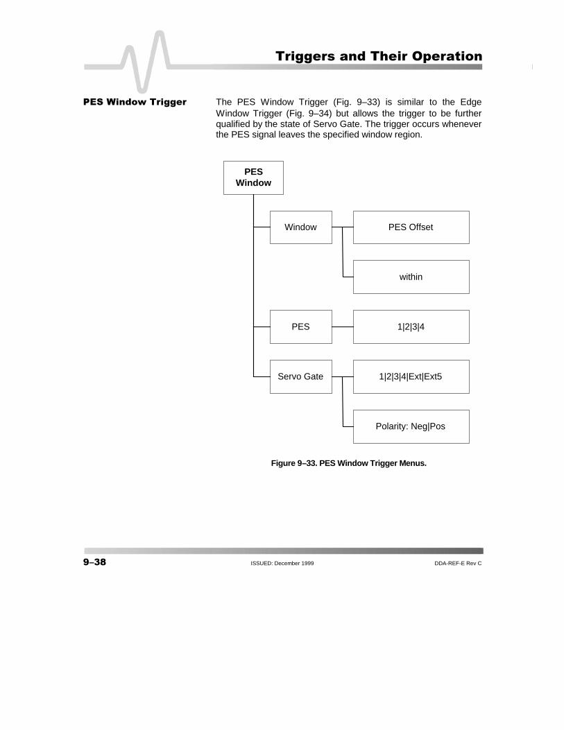
&���!���"�������� The PES Window Trigger (Fig. 9–33) is similar to the EdgeWindow Trigger (Fig. 9–34) but allows the trigger to be furtherqualified by the state of Servo Gate. The trigger occurs wheneverthe PES signal leaves the specified window region.
Figure 9–33. PES Window Trigger Menus.
PESWindow
Window
PES
Servo Gate
within
1|2|3|4
PES Offset
1|2|3|4|Ext|Ext5
Polarity: Neg|Pos

DDA-REF-E Rev C ISSUED: December 1999 ���
���
Figure 9–34. PES Window Trigger: while Servo Gate remains true, triggers whenever the PES signalleaves the window region. The broken upward-pointing arrows indicate potential triggers, which would
occur were other conditions met, while the bold ones indicate where triggers actually occur.
# # #
Generated Trigger
PES Signal
PES Offset
Window
Servo Gate
���� ISSUED: December 1999 DDA-REF-E Rev C
����������������� ������
BLANK PAGE