dc1000 can
TRANSCRIPT

7/27/2019 Dc1000 Can
http://slidepdf.com/reader/full/dc1000-can 1/33
Operating Instructions
8000013817 BAL, en
Operating InstructionsSwitch Mode Power SupplyDC 1000 CAN24/48/60 VDC
AEG Power Supply Systems GmbHDepartment: PSS V131Name: Gleitsmann / SchenuitRevision: 01Date: 13.09.2005
7/27/2019 Dc1000 Can
http://slidepdf.com/reader/full/dc1000-can 2/33
Switch Mode Power Supply DC1000 CAN
Page 2 of 33 8000013817 BAL, en
Table of Contents
Notes on these Operating Instructions............................................... 3
1. Safety Regulations!.............................................................. 5
1.1 Important Instructions and Explanations................................. 51.3 Danger during Maintenance and Repair Work........................ 51.4 Qualified Personnel................................................................ 61.5 Safety Awareness .................................................................. 61.6 Application ............................................................................. 61.7 Liability................................................................................... 71.8 Directives ............................................................................... 7
2. General Information ............................................................. 82.1 System Description ................................................................ 82.2 Type Overview DC 1000 CAN................................................ 92.3 Principle of Operation, Electrical ............................................ 9
2.4 Complete Circuit Diagram .................................................... 113. Functional Description of the Unit .................................... 12
3.1 Input..................................................................................... 123.2 Output / Characteristic Curve............................................... 123.3 Sequence Control ................................................................ 133.4 Monitoring Systems.............................................................. 153.4.1 Data Logger ......................................................................... 163.4.2 Input Voltage Monitoring System.......................................... 163.4.3 Output Voltage Monitoring System....................................... 173.4.4 Unit Temperature Monitoring System................................... 183.4.5 Unit Monitoring Systems ...................................................... 183.5 Switching ON / OFF with SMPS Tool ................................... 203.6 Parallel Operation ................................................................ 203.7 CAN Bus Interface X12 ........................................................ 213.8 RS-232 Service Interface X13.............................................. 213.9 Signalling ............................................................................. 213.10 Pin Assignments .................................................................. 22
4. Start-Up............................................................................... 234.1 Installation............................................................................ 234.2 Connection...........................................................................234.3 Connecting the DC Input / Loads ......................................... 244.4 Disconnection ...................................................................... 24
5. Operation ............................................................................ 255.1 Changing Unit Settings ........................................................25
6. Maintenance ....................................................................... 26
7. Troubleshooting................................................................. 277.1 No Output Voltage Present .................................................. 277.2 Output Voltage Deviation ..................................................... 27
8. Technical Data.................................................................... 288.1 General Technical Data........................................................ 288.2 Technical Data of the DC 1000 CAN Series......................... 31
9. Dimensional Drawing ......................................................... 33

7/27/2019 Dc1000 Can
http://slidepdf.com/reader/full/dc1000-can 3/33
Switch Mode Power Supply DC1000 CAN
Page 3 of 33 8000013817 BAL, en
Notes on these Operating Instructions
Duty to provide information
These operating instructions must be read carefully by all personsworking with or on the switch mode power supply prior to installationand commissioning.
These operating instructions are a composite part of the switch modepower supply.
The owner of this unit is obliged to communicate the full content of these operating instructions to all personnel transporting or startingthe switch mode power supply or performing maintenance or anyother work on the unit.
Validity
These operating instructions comply with the current technicalspecifications of the switch mode power supply at the time of publication. The contents do not constitute a subject matter of the
contract, but serve for information purposes only. AEG reserves the right to make modifications with regard to contentsand technical data in these operating instructions without prior notification. AEG cannot be held liable for any inaccuracies or inapplicable information in these operating instructions, as noobligation to continuously update the data and maintain their validity
has been entered into.
Warranty
Our goods and services are subject to the general conditions of supply for products of the electrical industry, and our general salesconditions. We reserve the right to alter any specifications given in
these operating instructions, especially with regard to technical data,operation, dimensions and weights. Claims in connection withsupplied goods must be submitted within one week of receipt, alongwith the packing slip. Subsequent claims cannot be considered.
AEG will rescind all obligations such as warranty agreements, servicecontracts, etc. entered into by AEG or its representatives without prior notice in the event of maintenance and repair work being carried outwith anything other than original AEG parts or spare parts purchasedfrom AEG.
Handling
These operating instructions for the switch mode power supply arestructured so that all work necessary for start-up, maintenance andrepair of the unit can be performed by qualified personnel.
Illustrations are provided to clarify and facilitate certain steps.
If danger to personnel and equipment cannot be ruled out in the caseof certain work, it is highlighted accordingly by pictograms explainedin chapter 1, Safety Regulations.

7/27/2019 Dc1000 Can
http://slidepdf.com/reader/full/dc1000-can 4/33
Switch Mode Power Supply DC1000 CAN
Page 4 of 33 8000013817 BAL, en
Abbreviations
The following abbreviations are used in these operating instructions:SMPS = Switch Mode Power SupplyPSC = Power Supply Controller
Hotline
Our service department is available on the hotline number givenbelow:
AEG Power Supply Systems GmbHEmil-Siepmann Strasse 32
D-59581 WarsteinGermany
+49 (2902) 763 100
FAX +49 (2902) 763 680
http://www.aegpss.de
Copyright
No part of these operating instructions may be transmitted,reproduced and/or copied by any electronic or mechanical meanswithout the express prior written permission of AEG.
© Copyright AEG 2005. All rights reserved.

7/27/2019 Dc1000 Can
http://slidepdf.com/reader/full/dc1000-can 5/33
Switch Mode Power Supply DC1000 CAN
Page 5 of 33 8000013817 BAL, en
1. Safety Regulations!
1.1 Important Instructions and Explanat ions
The instructions for operation and maintenance, as well as the
following safety regulations must be complied with to ensure thesafety of personnel as well as the continued availability of the unit. All personnel installing/dismantling, starting up, operating or servicingthe units must be familiar with and observe these safety regulations.Only trained and qualified personnel may perform the work described,using tools, equipment, test equipment and materials intended for thepurpose and in perfect working condition.
1.2 Accident Prevention Regulations
Compliance with the accident prevention regulations valid in therespective country of use and the general safety regulations in
accordance with IEC 364 is mandatory.The following must be observed prior to any work on the switch modepower supply:
- Disconnect the unit from the power supply.
- Secure against reclos ing.
- Verify that the unit is disconnected from the power supply.
- Earth and short circuit the unit.
- Provide protection by covers or barriers for anyneighbouring live parts.
1.3 Danger during Maintenance and Repair Work
CAUTION:The voltage applied to the unit can be fatal. Prior to start-upand/or maintenance work, always disconnect the unit from thepower supply and secure the unit against reclosing. The
capacitors must be discharged. Free-standing and movablecomponents can protrude into the work area and cause injuries.
ATTENTION:Considerable damage can be caused to equipment if unsuitablespare parts are used for repair work, if work is carried out by
unauthorised personnel, or the safety regulations are notobserved.
iNOTE:
Only trained and qualified personnel (refer to chapter 1.4) maywork on or in the vicinity of the unit while strictly observing thesafety regulations.

7/27/2019 Dc1000 Can
http://slidepdf.com/reader/full/dc1000-can 6/33
Switch Mode Power Supply DC1000 CAN
Page 6 of 33 8000013817 BAL, en
1.4 Qualified Personnel
The switch mode power supply may only be transported, installed,connected, started up, serviced and operated by qualified personnelwho are familiar with the pertinent safety and installation regulations. All work performed must be inspected by responsible experts.
The qualified personnel must be authorised by the responsible safetyofficer of the installation to perform the work required.
Qualified personnel is defined as personnel
- having completed training and gained experience in therespective field,
- familiar with the pertinent standards, rules and regulations andaccident prevention regulations,
- having received instruction on the mode of operation andoperating conditions of the switch mode power supply,
- capable of recognising and preventing dangers.
Regulations and definitions for qualified personnel can be found in
DIN 57105/VDE 0105 Part 1.
1.5 Safety Awareness
The personnel defined in chapter 1.4 are responsible for safety. Theymust also ensure that only suitably qualified persons are permitted tobe in the proximity of the unit or permitted access to the safety area.
The following points must be observed:
Al l working procedures which are detrimental to the safety of personsand the operation of the switch mode power supply in any way are
prohibited.
The unit may only be operated in perfect working condition.Never remove or render inoperable any safety devices.
All necessary operational measures must be initiated prior todeactivating any safety device in order to perform maintenance,repair or any other work on the unit.
Safety awareness also entails informing colleagues of any unsuitablebehaviour and reporting any faults detected to the respectiveauthority or person.
1.6 Application
The switch mode power supply is designed for use in power supplysystems and may only be used for a power supply in the describedinstallation position and operating mode with the maximumpermissible connection values as specified in these operatinginstructions. The unit may only be used for this intended purpose. It isnot permitted to make any unauthorised modifications to the unit or touse any spare parts or replacement parts not approved by AEG, or touse the unit for any other purpose.

7/27/2019 Dc1000 Can
http://slidepdf.com/reader/full/dc1000-can 7/33
Switch Mode Power Supply DC1000 CAN
Page 7 of 33 8000013817 BAL, en
The person responsible for the installation must ensure that
• the safety instructions and operating instructions are readilyavailable and are complied with,
• the operating conditions and technical data are observed,
• safety devices are used,
• the prescribed maintenance work is performed,• maintenance personnel is informed without delay or that the unit
is shut down immediately in the event of abnormal voltages or noise, high temperatures, vibrations or any similar effects, in order to detect the cause.
These operating instructions contain all the information required byqualified personnel for operating the unit. Additional information andexplanations for unqualified persons and for the use of the unit innon-industrial applications are not included in these operatinginstructions.
The warranty obligations of the manufacturer are only applicable if
these operating instructions are observed and complied with.
1.7 Liability
No liability is accepted if the switch mode power supply is used for applications not intended by the manufacturer. Any necessarymeasures for the prevention of injury or damage to equipment are theresponsibility of the owner or user. In the event of any claims inconnection with the switch mode power supply, please contact usquoting:
- Type designation
- Works number
- Reason for claim
- Period of use
- Ambient conditions
- Operating mode
1.8 Directives
The switch mode power supply units comply with the currentlyapplicable DIN and VDE regulations. VBG4 is met on the basis of compliance with VDE 0106 Part 100.
The requirements of VDE 0100 Part 410, "Functional extra-lowvoltage with safe isolation", have been complied with whereapplicable.
The CE sign on the unit confirms compliance with the EC outlinedirectives for 73/23 EEC – Low voltage and for 89/339 EEC –Electromagnetic compatibility if the installation and start-upinstructions described in the operating instructions are observed.

7/27/2019 Dc1000 Can
http://slidepdf.com/reader/full/dc1000-can 8/33
Switch Mode Power Supply DC1000 CAN
Page 8 of 33 8000013817 BAL, en
2. General Information
2.1 System Description
The DC 1000 CAN switch mode power supply provides an output
power of approx. 1 kW.Typical applications include use as a DC power supply unit. In thiscase, it is possible to have positive earthing, negative earthing,earthing of the battery centre or even a non-earthed DC input or output busbar. The SMPS is a preassembled unit ready for connection.
The SMPS is intended for connection to a DC power supply systemwith 110 VDC or 220 VDC. There is electrical isolation between theDC input, the DC output as well as all signal terminals and serialinterfaces.
The switch mode power supply can be operated both as a stand-alone unit and in parallel with several SMPS units of the same type.
The characteristic curve slope of the output voltage results in an evencurrent distribution.
The switch mode power supply works following a CVCC curve in acc.with DIN 41772 or DIN 41773.
The connections, DC input, DC output, a remote control input RemoteOFF and a potential-free changeover contact for indicating faults canbe accessed from the front. Furthermore, the front of the unit alsofeatures an RS232 service interface and a CAN bus interface.Several SMPS units can be controlled and monitored by a master control unit, the PSC100, by means of a CAN bus. The PSC100offers many features, including a changeover of characteristic curves,
charge voltage adjustment depending on the battery temperature, etc.The display elements, LEDs for charging and fault messages, areinstalled in the front of the unit.
It is possible to view a data logger with a PC via the service interface.
Due to its excellent efficiency, the SMPS is of compact design as a19 inch rack with 2 height modules.
The unit is ready for installation in module racks in accordance withDIN 41494.

7/27/2019 Dc1000 Can
http://slidepdf.com/reader/full/dc1000-can 9/33
Switch Mode Power Supply DC1000 CAN
Page 9 of 33 8000013817 BAL, en
2.2 Type Overview DC 1000 CAN
Type designation Connectionvoltage
Output voltage Outputcurrent
G110 G24/30 BWrg-Cpü 110 VDC 24 VDC 30 A
G220 G24/30 BWrg-Cpü 220 VDC 24 VDC 30 A
G110 G48/15 BWrg-Cpü 110 VDC 48 VDC 15 A
G110 G60/15 BWrg-Cpü 110 VDC 60 VDC 15 A
G220 G48/15 BWrg-Cpü 220 VDC 48 VDC 15 A
G220 G60/15 BWrg-Cpü 220 VDC 48 VDC 15 A
Table 1 Type overview DC 1000 CAN
2.3 Principle of Operat ion, Electrical
The switch mode power supply is powered by a DC voltage mains. A soft-start device limits the input current to the nominal current of theunit. Transistors generate a 80 kHz AC voltage from the rectified andstepped-up voltage. With the aid of a transformer, the following isaccomplished:
- electrical isolation,
- voltage adjustment to the secondary side.
The 80 kHz AC voltage on the secondary side is rectified by diodes.The voltage ripple is reduced using a downstream output filter. Theoutput voltage and output current are controlled via pulse-widthmodulation by the transistor switches on the primary side.
Power derating protects the SMPS from thermal overload if the heatsink temperature is too high.
The SMPS controls the voltage at the unit output terminals. Thevoltage step inclination of the CVCC curve is 1% in order to distributethe current between units connected in parallel. An SMPS Toolmakes it possible to alter all the important operating parameters, suchas the output voltage and output current, as well as variousmonitoring limit values.
On the front of the unit are located a green "Charging" LED and four red LEDs: "Fault", output overvoltage "UO>", output undervoltage"UO<" and overtemperature "Temp.>". A potential-free changeover contact configured as an open-circuit fault contact is used for signalling faults to remote equipment. There is a time delay betweenthe "Fault" LED and the relay.
All control modules are powered by an auxiliary power supply whichis in turn powered from the DC input side.

7/27/2019 Dc1000 Can
http://slidepdf.com/reader/full/dc1000-can 10/33
Switch Mode Power Supply DC1000 CAN
Page 10 of 33 8000013817 BAL, en
The SMPS is equipped with an isolated RS232 service interfaceoperating close to the earth potential. This X13 interface enables theSMPS to be operated using a conventional PC and an SMPS Tool.Operation is described in detail in separate operating instructions.
The CAN interface is also potential-free and close to the earthpotential. It makes it possible to connect several SMPS units in a
system to a central controller, the PSC100. This control unit controlsand monitors all connected SMPS units and forms the basis for activecurrent distribution control. Furthermore, a central fault signal isgenerated. Simple wiring using the CAN bus ensures that the systemcan be set up quickly and tested in a straightforward manner. Inoperation with a PSC100, all SMPS units connected to the systemmust have addresses between 1 and 31; when operating without aPSC100, however, the SMPS address must always be set to 0. Theaddress is set using the SMPS Tool. Operation and settings using thePSC100 are described in detail in separate operating instructions.
The unit can be switched off by jumpering X18.1 – X18.2 using a
floating X18 Remote OFF control input.The complete circuit diagram on the next page shows the functionalunits described here.

7/27/2019 Dc1000 Can
http://slidepdf.com/reader/full/dc1000-can 11/33
Switch Mode Power Supply DC1000 CAN
Page 11 of 33 8000013817 BAL, en
2.4 Complete Circui t Diagram
T r a n s -
f o r m e r
X 1
P r i m a r y p o w
e r s e c
t i o n
A 1
D C - D C
t r a n
s f o r m e r
T 1
R e c t i f i e r a n d f i l t e r i n g
I n t e r f e r e n c e
s u p p r e s s i o n
L +
L -
X 2
L
+
L
-
P
E
A 5
M i c r o c o n t r o l l e r
E l e c t r i c a l
i s o l a t i o n
D C
i n t e r m e d
i a t e c i r c u i t v o l t .
I n p u t
v o l t a g e
F i l t e r
A c t u a l v a l u e v o l t a g e
a n d c u r r e n t
D C - D C
O N
X 1 1
1 2 3
F a u
l t
X 1 2
X 1 3
C A N
B u s
R S 2 3 2
S
e r v
i c e
C h a r g i n g
F a u l t , U O > ,
U O < ,
T e m p . >
D C - D C
t r a n s f o r m e r
c o n t r o l
A 2
S e c o n
d a r y p o w e r s e c
t i o n
C o n
t r o l a n
d
m o n
i t o r i n g
A u x
. v o l t a g e
T e m p .
C o n t r o l p a r a m e t e r S
e t p o i n t s
A u x i l i a r y
p o w e r
s u p p l y
u n i t
D C - D C
t r a n
s f o r m e r
a c t i v a t i o n
P o w e r s e c t i o n
t e m p e r a t u r e
S o f t s t a r t r e l a y O N
P E
X 1 8
1 2
R
e m o
t e O F F
S o f t s t a r t
I n p u t o
v e r v o l t a g e
O v e r
v o l t a g e m o n i t o r
Figure 1 Complete circuit diagram DC 1000 CAN

7/27/2019 Dc1000 Can
http://slidepdf.com/reader/full/dc1000-can 12/33
Switch Mode Power Supply DC1000 CAN
Page 12 of 33 8000013817 BAL, en
3. Functional Descr ipt ion of the Unit
The respective unit settings can be found in the Technical Data Sheet(refer to chapter 8).
3.1 Input
The switch mode power supply DC 1000 CAN is operated on a110 VDC or 220 VDC system. The SMPS can achieve its nominaloutput within the limits specified in the technical data.
The input is protected against short-circuits outside the unit.Protection must therefore be provided individually for each rack. It isessential to comply with the nominal amperage and fuse protectioncharacteristics specified in the technical data!
An integrated run-up stage limits the making current of the switchmode power supply to a value smaller than the nominal input current.
CAUTION:
The unit must not be operated unearthed for safety reasons!
The auxiliary power supply of the SMPS starts operating when aninput voltage is applied. The auxiliary power supply provides power toall electronics modules; the LEDs display the unit status and theSMPS can be operated via the serial interfaces.
3.2 Output / Characterist ic Curve
The SMPS output is electrically isolated from the DC input, theinterfaces and the fault relay contact. This means operation ispossible with non-earthed DC voltage, an earthed positive pole or an
earthed negative pole.
The output curve is a CVCC curve in accordance with DIN 41772 withapprox. 1% voltage step inclination. Due to the inclination, the loadcan be distributed quite evenly when several SMPS units areoperated in parallel.
The pivot of the inclined curve is at 50% Irated. The nominal value of
the output voltage is defined at 50% Irated. The voltage step
inclination in relationship to the output current is determined by thehardware.
Ua
50% 100%
100%
Ia
Figure 2 Output curve

7/27/2019 Dc1000 Can
http://slidepdf.com/reader/full/dc1000-can 13/33
Switch Mode Power Supply DC1000 CAN
Page 13 of 33 8000013817 BAL, en
3.3 Sequence Control
The auxiliary power supply of the SMPS goes into operation when theinput voltage is connected and supplies all electronic modules.
The operating characteristics differ fundamentally according to
whether operation is with CAN (address 1 to 31) or withoutCAN (address = 0).
In operation without CAN, the SMPS starts up after the inputvoltage is applied. However, it does not start up if it has beenswitched off using the SMPS Tool or via the Remote OFF remotecontrol input. The voltage and current setpoints stored in the SMPSand the monitoring limit values for DC overvoltage and undervoltageare used.
In operation with CAN, the SMPS switches on when it receives an"ON" CAN command from the PSC100. However, it does not switchon if it has been switched off via the Remote OFF remote controlinput and with the SMPS Tool. Switch-on occurs after a 10-second
delay if there is no CAN communication. The internal setpoints areused if there is no CAN communication; if CAN communication isfunctioning, the SMPS operates according to the values specified bythe PSC100 control unit.
iNOTE:In operation with PSM/PSC100, the basic values for voltage,current, output overvoltage and output undervoltage monitoringare specified for the SMPS units by the PSM/PSC100.
The SMPS Tool PC software enables the SMPS units to beconfigured so that individual values will not be overwritten by thePSM/PSC100.
The default setting is that the PSM/PSC100 overwrites the basicvalues of the SMPS units!
No faults are ever signalled by an SMPS which has input power andis switched off; the monitoring systems are blocked, the fault relaygoes over to fault-free status and the LEDs are off. The relay contactis configured as an open-circuit fault signal, i.e. a fault is signalledwhen it is de-energised. As a result, even a total SMPS failure, e.g.lack of input voltage, is detected. The signalling functions can beconfigured with the SMPS Tool.
The SMPS changes to the ON status when it is switched ON; the
monitoring systems are active. Monitoring covers four different typesof faults: Deactivating faults, self-acknowledging faults, signallingfaults and faults which trigger a restart.
Deactivating faults cause the SMPS to be switched off permanently.They can only be acknowledged by OFF/ON (input voltage OFF/ON)or using the RESET or unlock functions of the SMPS Tool. Anexample of this type of fault is output overvoltage."Fault" LED flashing quickly
Self-acknowledging faults switch off the SMPS but restart it whenthe fault is no longer present. An example of this type of fault is inputovervoltage."Fault" LED permanently lit

7/27/2019 Dc1000 Can
http://slidepdf.com/reader/full/dc1000-can 14/33
Switch Mode Power Supply DC1000 CAN
Page 14 of 33 8000013817 BAL, en
Signalling faults do not influence the control of the SMPS although afault signal is generated. An example of this type of fault is outputundervoltage.The "Fault" LED flashes briefly with long pauses.
Faults which trigger a restart generate a hardware reset and restartthe unit. The unit returns to its previous status.The "Fault" LED and "Charging" LEDs flash alternately.
All faults activate the "Fault" LED and the fault signalling relay. Allfaults can be acknowledged by switching the unit OFF (input voltageOFF) or using the RESET or Unlock functions of the SMPS Tool.
The green "Charging" LED comes on when the unit is supplyingoutput current.
The LEDs on the front of the unit have the following functions:
green Charging (flashes if derating)
red Fault (collective fault)
red UO< (output undervoltage)
red UO> (output overvoltage)
red Temp.> (overtemperature)
Red, flashing (Temp.>) - no CAN communication (onlywith addr. 1 to 31)
Red ("Fault") / green("Charging") flashingalternately
Program fault (watchdog error)
Red ("Fault") / green("Charging") flashingtogether
Device address only displayed when theinput voltage is applied and the device isin the 'External off' state. The LEDs flashtogether 1-31 times.
Table 2 LEDs on the front of the unit
The relationships are illustrated in the "Phase diagram of sequencecontrol" chart.
7/27/2019 Dc1000 Can
http://slidepdf.com/reader/full/dc1000-can 15/33
Switch Mode Power Supply DC1000 CAN
Page 15 of 33 8000013817 BAL, en
OFF
----------------------
Status: Unit STOP
Deactivating
fault
------------------Status: Unit STOP -
Fault
Self-acknowledging
fault
-------------------------
Status: Unit STOP -
Fault
CAN command ONand tool command ON
CAN command OFFor tool co mmand OFF
Self-ack. fault
Self-ack. faultor
CAN command unlockor tool command unlock
CAN command OFFor tool co mmand OFF
Deactivating fault
Deactivating fault
Power up
CAN command unlockor tool command unlock
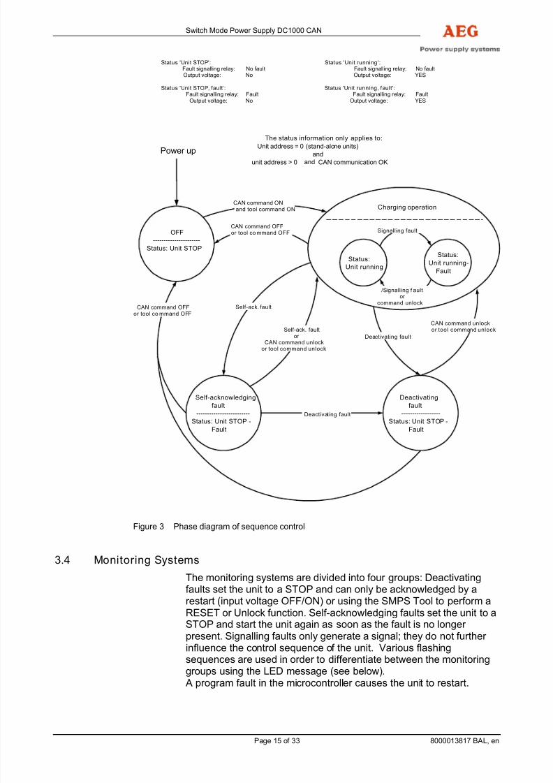
Status 'Unit STOP': Status 'Unit running':Fault signalling relay: No fault Fault signalling relay: No faultOutput voltage: No Output voltage: YES
Status 'Unit STOP, fault': Status 'Unit running, fault':Fault signalling relay: Fault Fault signalling relay: Fault
Output voltage: No Output voltage: YES
Signalling fault
/Signalling f aultor
command unlock
Charging operation
Status:
Unit running
Status:
Unit running-
Fault
The status information only applies to:Unit address = 0 (stand-alone units)
and
unit address > 0 and CAN communication OK
Figure 3 Phase diagram of sequence control
3.4 Monitoring Systems
The monitoring systems are divided into four groups: Deactivatingfaults set the unit to a STOP and can only be acknowledged by arestart (input voltage OFF/ON) or using the SMPS Tool to perform aRESET or Unlock function. Self-acknowledging faults set the unit to aSTOP and start the unit again as soon as the fault is no longer present. Signalling faults only generate a signal; they do not further influence the control sequence of the unit. Various flashingsequences are used in order to differentiate between the monitoringgroups using the LED message (see below).
A program fault in the microcontroller causes the unit to restart.

7/27/2019 Dc1000 Can
http://slidepdf.com/reader/full/dc1000-can 16/33
Switch Mode Power Supply DC1000 CAN
Page 16 of 33 8000013817 BAL, en
All faults activate the "Fault" LED and the remote fault signal(collective fault). All faults can be acknowledged by a restart. Aprogram fault also requires acknowledgement by switching the inputvoltage off and back on, or using the SMPS Tools to unlock the unit.
The assignment of the monitoring systems to the fault types is as
follows:
Deactivating faults:
"Fault" LED flashing quickly
Output overvoltage Reference voltage fault (unit monitoring system) Electronics power supply (unit monitoring system) Heat sink temperature sensor (unit monitoring system)
Ambient temperature sensor (unit monitoring system) Intermediate circuit fault (unit monitoring system)
Self-acknowledging faults:
"Fault" LED permanently lit
Undervoltage at input Overvoltage at input Heat sink overtemperature Ambient temperature
Signalling faults:
Brief flashing of the "Fault" LED with long pauses
Output undervoltage Power circuit faulty Self-test (unit monitoring system)
CAN bus communication (unit monitoring system)
Monitoring systems which trigger a restart:
Red ("Fault") / green ("Charging") flashing alternately
Program fault = watchdog
3.4.1 Data Logger
The unit contains a data logger that stores all entries in a non-volatilememory. If the data logger is full (max. 100 entries), the entry of longest standing is overwritten. The data logger can be read out anddeleted using the BLG-Tool.
Each monitoring function results in an entry in the data logger.
3.4.2 Input Voltage Monitoring System
The input voltage monitoring systems ensure the intrinsic safety of the unit against overloads and overvoltages. The monitoring systemsare self-acknowledging. The "Fault" LED lights up if there is a fault.The SMPS "Unit STOP" is set if the input voltage is outside thepermitted range.
Input undervoltage monitoring system:
The unit is set to a STOP if the input voltage falls below the minimum
level.
Display: "Fault" LED is onMessage: Signalling relay "Fault"

7/27/2019 Dc1000 Can
http://slidepdf.com/reader/full/dc1000-can 17/33
Switch Mode Power Supply DC1000 CAN
Page 17 of 33 8000013817 BAL, en
Operation of the unit is restored after a delay when the input voltageonce more exceeds the return value.
Input overvoltage monitoring system:
The "Unit STOP" is set if the input voltage exceeds the maximum
level. Display: "Fault" LEDMessage: Signalling relay "Fault"
Operation of the unit is restored after a delay when the input voltageonce more falls below the return value.
3.4.3 Output Voltage Monitoring System
Output overvoltage monitoring system:
The output voltage monitoring system is both deactivating and self-acknowledging. The "Unit STOP" is set on the first occasion that the
maximum output voltage is exceeded. The "Fault" and "Uo>" LEDs
light up. The fault is acknowledged, the SMPS started and the "Fault"and "Uo>" LEDs are switched off if the voltage falls back below the
return value within a certain period of time. However, the SMPS isswitched off permanently if the overvoltage continues; the "Fault" LEDflashes and the "Uo>" LED remains on. The SMPS "Unit STOP" is set
and the unit may be restarted if overvoltage is once again detectedfollowing an automatic restart. Following the third switch-off, the "UnitSTOP" is set permanently. The "Fault" LED flashes and the"Uo>" LED lights up.
Display: "Fault" and "Uo>" LEDsMessage: Signalling relay "Fault"
The monitoring system can be acknowledged by switching the unitOFF (input voltage OFF/ON). The monitoring limit values can beadjusted. The setting and the setting range are specified in thetechnical data.
Output undervoltage monitoring system:
The undervoltage monitoring system is a signalling system. A fault isgenerated if the output voltage falls below the minimum level; the
SMPS is unaffected and continues to operate.Display: "Fault" and "Uo<" LEDs
Message: Signalling relay "Fault"
When the output voltage rises above the return value, the fault isacknowledged. The monitoring limit value can be adjusted.
The green "Charging" LED will also flash if the output undervoltagemonitoring system is triggered because the input voltage is too lowand the power has to be derated.

7/27/2019 Dc1000 Can
http://slidepdf.com/reader/full/dc1000-can 18/33
Switch Mode Power Supply DC1000 CAN
Page 18 of 33 8000013817 BAL, en
3.4.4 Unit Temperature Monitoring System
The temperature in the power section and in the electronics of theunit is measured and monitored for the protection of the SMPS. Thepower is derated if the temperature exceeds a limit value.
Unit Temperature Monitoring SystemIf the temperature still continues to rise, the temperature monitoringsystem sets the SMPS "Unit STOP". This monitoring system is self-acknowledging.
Display: "Fault" and "Temp.>" LEDs litMessage: Signalling relay "Fault"
The unit restarts and the fault message is acknowledged when thetemperature drops back below a return value. In the event of a fault, acheck must be performed to ensure that the cooling air temperatureand quantity are sufficient. The triggering and return values cannot bealtered.
3.4.5 Unit Monitoring Systems
Temperature sensors
This fault is deactivating. The "Unit STOP" is set if there is a cablebreak or a short circuit on the temperature sensors. No settings canbe changed. Check for a discontinuity or short circuit in the sensor
cables to the sensors. Fit new sensors if necessary.
Display: "Fault" LED flashes and "Temp.>" LED lights upMessage: Signalling relay "Fault"
The fault is acknowledged by switching the unit OFF/ON.
Reference voltage
This fault is deactivating. The reference voltage monitoring systemdetects an incorrect response of the internal reference voltagesources on the microprocessor card. The monitoring system sets theunit to a STOP. No settings can be changed.
Display: "Fault" LED flashesMessage: Signalling relay "Fault"
The fault is acknowledged by switching the unit OFF/ON. The SMPSshould continue to be observed if it then operates without any faults.Send the SMPS back to the manufacturer if the fault reoccurs.
Power supply to electronics
This fault is deactivating. The monitoring system for the power supplyto the electronics detects if there is a fault in the auxiliary power supply voltages and sets the unit to a STOP. No settings can bechanged.
Display: "Fault" LED flashesMessage: Signalling relay "Fault"
The fault is acknowledged by switching the unit OFF/ON. The SMPSshould continue to be observed if it then operates without any faults.
Send the SMPS back to the manufacturer if the fault reoccurs.

7/27/2019 Dc1000 Can
http://slidepdf.com/reader/full/dc1000-can 19/33
Switch Mode Power Supply DC1000 CAN
Page 19 of 33 8000013817 BAL, en
Self-test
This monitoring system is a signalling system. When the input voltageis switched on, parameters stored in a non-volatile memory arechecked for plausibility. In the event of an error, default values fromthe program memory are used in order to permit emergencyoperation of the unit. These values may not correspond to the original
settings, so the defective SMPS should soon be replaced andreturned to the manufacturer for checking. The "Fault" LED flashes.
The settings cannot be altered.
Display: "Fault" LED flashes
Message: Signalling relay "Fault"
Power circuit faulty
This is a signalling fault. The power circuit monitoring system detectsa fault in the SMPS by monitoring an auxiliary voltage in thesecondary circuit and in the unit output current. The auxiliary voltageis not backed-up from the DC busbar. Its value will be the same as
that of the DC busbar if the unit is operating correctly. If a fault occursin the power circuit, the auxiliary voltage drops to zero and no outputcurrent flows (in contrast to a short circuit).
Display: "Fault" LED flashesMessage: Signalling relay "Fault"
The monitoring system can be acknowledged by switching the unitOFF/ON.
No settings can be changed.
Watchdog
The watchdog monitors the microcontroller program to make sure it isrunning correctly. In the event of a program fault, a software RESETof the processor is triggered and a restart is generated. The unitbehaves in the same way as on start-up following the connection of the input voltage, the only difference being that the signalling faultcontinues to be active. The program fault is signalled as follows: Thered and green LEDs flash alternately.
Display: "Fault" and "Charging" LEDs flash alternatelyMessage: Signalling relay "Fault"
The monitoring system can be acknowledged by switching the unitOFF/ON.
No settings can be changed.
Communication CAN bus
This monitoring system is only active if a unit address greater than 0is set, i.e. when operating with the PSC100.In this operating mode, the control commands and voltage setpointsare received via the CAN bus. If there is no CAN command within aperiod of more than 10 seconds, the SMPS uses its internally storedvalue as the nominal voltage. A signalling fault is generated in order to indicate this.The monitoring system is deactivated if the address is 0.
Display: "Temp.>" LED flashes
Message: Signalling relay "Fault"

7/27/2019 Dc1000 Can
http://slidepdf.com/reader/full/dc1000-can 20/33
Switch Mode Power Supply DC1000 CAN
Page 20 of 33 8000013817 BAL, en
3.5 Switching ON / OFF with SMPS Tool
The unit can be operated using the SMPS Tool in the same way asusing an ON/OFF switch.Switching OFF acknowledges all faults (except for the CAN bus fault)and the SMPS switches to fault-free status. In operation without aPSC100 (address = 0), the unit follows the "ON/OFF" controlcommand directly. With a PSC100 (address 1 to 31), the unit canalways be switched OFF. However, the SMPS only switches ONwhen it is switched on both on the SMPS Tool and the PSC100.
A unit which is switched off is only off from a logical standpoint; theelectronics are still powered up and communication continues without
disruption.
The control command from the SMPS Tool is stored in a non-volatilememory in the SMPS. This means the "old" command is stillperformed even after a hardware reset.It may be a good idea to switch off a unit if it is being operated usingone PSC100 together with several SMPS units, if it should not
operate (e.g. backup unit) but is not allowed to generate a CAN busfault which would be triggered if the SMPS were unpowered! All SMPS units are delivered in the switched-on status. This meansthe units operate when the input voltage is applied!
3.6 Parallel Operation
Since the units can be connected in parallel, it is possible to buildsystems for redundant operation in accordance with the n+1 principle.Due to the inclination of the individual voltage curves, the load can bedistributed quite evenly in the case of parallel operation of several
switch mode power supply units (±10% of the nominal system
current). An important prerequisite is that the unit outputs areconnected to the load or the DC busbar with cables of the same crosssection and length. Also, the output voltages must be set to the samevalues.
When operating with a PSC100, active current distribution controlensures that the load is evenly distributed, even when the wiring isunsymmetrical.
Selective DC monitoring of the individual switch mode power supplyunits is assured even without external decoupling diodes in theoutput.If the switch mode power supply units are interconnected in the
respective output without decoupling diodes or fuses, the systemwiring must be dimensioned for the max. possible current.When SMPS units are connected in parallel with decoupling diodes inthe line to the DC busbar, the diodes should be in the non-earthedpole. The advantage of a system with decoupling diodes is that thecross-sections of the cables to the SMPS units only have to beselected for the current of one SMPS and, if one SMPS in the systemfails due to DC overvoltage, there will not be any reverse voltageflowing back to the functioning SMPS units which could possiblydamage them.

7/27/2019 Dc1000 Can
http://slidepdf.com/reader/full/dc1000-can 21/33
Switch Mode Power Supply DC1000 CAN
Page 21 of 33 8000013817 BAL, en
3.7 CAN Bus Interface X12
CAN bus plug X12 allows the Supervision PSC100 to take over all thecontrol and monitoring systems of the units.
The X12 CAN bus is electrically isolated from other switching
components and is kept c lose to the earth potential by means of resistors.
3.8 RS-232 Service Interface X13
The RS232 interface and a special "SMPS Tool" PC software enableall important operating parameters to be set. In addition, the SMPScan be controlled, faults acknowledged and the data logger can beread out and reset. Operation is described in detail in a separatedocument.
Interface X13 is electrically isolated from other switchingcomponents and is kept c lose to the earth potential by means of
resistors.
3.9 Signalling
The following signals are indicated via LEDs on the front panel of theunit.
Green LED Charging Unit can output power,output voltage present
Red LED Fault Collective fault
Red LED UO< Output undervoltage
Red LED UO> Output overvoltage
Red LED Temp.> Overtemperature
Table 3 Signalling on the front of the unit
Remote signalling is implemented using a potential-free relaychangeover contact. It is configured as an open-circuit fault contact.There is a time delay between the "Fault" LED display and the relaysignal.
The max. contact load is specified in the technical data.
iNOTE:
The SMPS Tool PC software enables the SMPS units to beconfigured so that individual faults do not affect the fault relay.
The default setting is that all faults activate the fault relay!
ATTENTION:
The relay contact has a gold-plated surface. This meanssignalling is also possible via "dry circuits", i.e. with low signalvoltages and currents. However, applying a higher voltage or
current to the relay contact will destroy the gold plating andprevent the signalling function from operating with "dry circuits"!

7/27/2019 Dc1000 Can
http://slidepdf.com/reader/full/dc1000-can 22/33
Switch Mode Power Supply DC1000 CAN
Page 22 of 33 8000013817 BAL, en
3.10 Pin Assignments
X1 DC input
Positive L+ Negative L-
Earth conductor
X2 DC output
Positive L+ Negative L-
Protective earth on housing
X11 remote signal, potential-free relay contact
1 NC 2 C 3 NO
"Fault" In the event of a signal, X11:1 – 2 closesor X11:2 – 3 opens
X18 remote signal input Remote OFF
1 2
Bridge X18:1 – X18.2 switches the unit off
X12 CAN
1, 6, 7 CAN-Gnd2, 5 R-Gnd
3 CAN-L 4 CAN-H 8,9,10 CAN supply +8 V 11, 12, 13 not used 14, 15 Control line
X13 Service RS-232
1 not assigned 2 TXD 3 RXD 4 not assigned 5 Gnd 6 not assigned 7 not assigned 8 not assigned 9 not assigned

7/27/2019 Dc1000 Can
http://slidepdf.com/reader/full/dc1000-can 23/33
Switch Mode Power Supply DC1000 CAN
Page 23 of 33 8000013817 BAL, en
4. Start-Up
4.1 Installation
The switch mode power supply units (SMPS) must be installed in
suitable module racks in acc. with DIN 41494.The SMPS functions with natural air cooling. The supply air temperature must not exceed 45 °C. If several units are installed oneabove the other in one cabinet, there must be either a forced-air cooling system installed, or a vertical distance between the units of atleast 134 mm = 3 height modules must be guaranteed. Air guidesmust be installed between the installation levels in such a way thatthe air intake temperature of the individual installation levels does notexceed the permanently permissible ambient temperature. Cabinetsmust be designed for a maximum ambient temperature of 40 °C. Thepower loss per unit is approx. 150 W.
4.2 Connection
Before connecting the unit to the DC input voltage, ensure that thevoltage given on the nameplate complies with the supplied DCvoltage. The DC input is connected with a 3-pin screw terminal (L+, L-, PE)on the front of the unit (X1). If one pin on the output side is grounded,the SMPS must be grounded via the separate PE connection on thefront of the unit. In this case, the PE conductor on the input side mustnot be connected (ground loops). The cross-section of the PEconductor must be chosen in accordance with VDE 0100 Part 540depending on the type of installation.
The DC connection is made using screw terminals (X2) on the front of the unit.
If decoupling d iodes or fuses are used in the DC outputconnection, they must be installed in the non-earthed pole.
X11 for remote signalling, X18 for remote switching OFF andX12 CAN bus can be connected if required, however they are notrequired for operation.
ATTENTION:Depending on the system configuration, the remotesignalling connection may still carry a high voltage even
when all other connections have been unplugged from theSMPS!

7/27/2019 Dc1000 Can
http://slidepdf.com/reader/full/dc1000-can 24/33
Switch Mode Power Supply DC1000 CAN
Page 24 of 33 8000013817 BAL, en
4.3 Connecting the DC Input / Loads
Prior to commissioning, it is essential to complete all the wiring and tocheck it! The unit setting must be altered if necessary (see 5.1).The switch mode power supply has an amplified smoothing modulewith electrolytic capacitors in the output. Connecting the de-energised
capacitors to the DC output busbar by engaging the DC outputisolator or the DC output fuse results in a powerful charging currentsurge which could damage the SMPS. This high charging currentshould be avoided by switching the unit on before engaging the DCoutput isolator. This is the only way to ensure the capacitors arecharged to the unit output voltage with a high charging stage.
It is only then possible to close the output circuit by engaging the DCoutput isolator or the DC output fuse.
The output circuit can be closed immediately in the case of units withan external decoupling diode in the connection to the DC outputbusbar.
ATTENTION:Observe correct polarity of the DC lines.
4.4 Disconnection
CAUTION:Even when switched off , the switch mode power supply cancarry vo ltage from charged capacitors and external signals.For this reason, the terminals must be checked prior todismantling the unit to ensure that they are de-energised.
The capacitors can be discharged using an external resistor oninput terminals X1 or output terminals X2.- Disconnect the input voltage.
- Disconnect the SMPS output from the loads / the battery
- Disconnect interfaces X12 and X13
- Disconnect plugs X11 and X18

7/27/2019 Dc1000 Can
http://slidepdf.com/reader/full/dc1000-can 25/33
Switch Mode Power Supply DC1000 CAN
Page 25 of 33 8000013817 BAL, en
5. Operation
The SMPS is delivered with the factory settings listed in the technicaldata.
5.1 Changing Unit Settings
If other output voltage settings are required or if the monitoring limitsare to be changed, the required settings must be made using theSMPS Tool.The SMPS is equipped with an electrically isolated RS232 serviceinterface operating close to the earth potential. This X13 interfaceenables the SMPS to be operated with a conventional PC and theSMPS Tool.For example, the values set for one SMPS can be downloaded,stored in a file and uploaded to other SMPS units. In this way, youcan be certain that all the SMPS units in a system have the same
settings.When the SMPS units are operated with the PSC100 centralcontroller, the units must be addressed using the SMPS Tool. Addresses between 1 and 31 are permitted; each address is onlyallowed to be assigned once in a system! The exact procedure isdescribed in the operating instructions for the PSC100.Operation of the SMPS Tool is described in detail in separateoperating instructions.
ATTENTION:Setting the SMPS incorrectly can result in (possibly irreparable)
damage to the connected loads!
The setting ranges of the SMPS have been set to prevent the SMPSfrom being damaged.

7/27/2019 Dc1000 Can
http://slidepdf.com/reader/full/dc1000-can 26/33
Switch Mode Power Supply DC1000 CAN
Page 26 of 33 8000013817 BAL, en
6. Maintenance
CAUTION:
Disconnect the unit from the power supply prior to all maintenancework. Always observe the safety regulations! (Refer to chapter 1.)
The SMPS is made up of state-of-the-art components which arepractically non-wearing. We do, however, recommend regular visualchecks and functional tests of the unit to maintain its operationalreliability and availability.
When visually inspecting the unit, check whether:
- there is any mechanical damage, or foreign bodies arepresent,
- any conductive dirt or dust has accumulated in the unit,
- Accumulation of dust affects heat supply and dissipation,
If large quantities of dust have accumulated, the unit should as aprecaution be cleaned using dry compressed air, in order to ensureadequate heat dissipation.
The intervals at which visual checks should be performed are largelydetermined by the site conditions. The unit must not be operated inan aggressive atmosphere.

7/27/2019 Dc1000 Can
http://slidepdf.com/reader/full/dc1000-can 27/33
Switch Mode Power Supply DC1000 CAN
Page 27 of 33 8000013817 BAL, en
7. Troubleshooting
CAUTION: All work on the unit may only be carried out by specially trainedqualified personnel. Always observe the safety regulations! (Refer to chapter 1.)
7.1 No Output Vol tage Present
- Input voltage present or correct polarity?
- Has the SMPS been switched off using the SMPS Tool?
- Is X18 Remote OFF activated? Disconnect the plug!
- Has the SMPS been switched off using the CAN bus?Disconnect the CAN, perform a hardware reset!
- Incorrect polarity or short circuit on output?
- With parallel operation: Ext. Polarity reversal on decouplingdiodes?
- Has the Uo> monitoring system responded ("Uo>" LED isON)? Perform a hardware reset and check the Uo> setting
If all aforementioned points are OK, proceed as follows:
- Unscrew the cover.
- Observe the safety instructions on the front of the unit!
- Check that the plug connectors are inserted correctly
It the fault cannot be eliminated, return the unit to the works for repair enclosing a fault description.
7.2 Output Vol tage Deviat ion- Is the unit operating with current limitation due to overload?
Reduce the load!
- Is the unit operating with derating because the ambienttemperature is too high?Improve the cooling!
- Is the UO setting incorrect?
Adjust the output voltage!

7/27/2019 Dc1000 Can
http://slidepdf.com/reader/full/dc1000-can 28/33
Switch Mode Power Supply DC1000 CAN
Page 28 of 33 8000013817 BAL, en
8. Technical Data
8.1 General Technical Data
Making current...............................< nominal input current
Characteristic curve.......................CVCC curve in acc. withDIN 41772 or 41773
Manufacturing and type test ..........In acc. with DIN 60146 Part 1-1
Emitted interference to EN 61000-6-3
- Conducted interference ..............In acc. with EN 55011/55022Input class "A"Output class "A"
- Emission .....................................In acc. with EN 55011/55022
Class "B"
Immunity to interference in acc. with EN 61000-6-2
- Housing.......................................ESD test in acc. with EN 61000-4-24 kV contact, 8 kV air dischargeHF field in acc. with EN 61000-4-310 V/m (80 MHz - 1 GHz)
- Power cables...............................Burst test in acc. withEN 61000-4-4, 2 kVSurge test in acc. withEN 61000-4-5,
0.5 kV asymmetrical;0.5 kV symmetricalConducted HF 10 Vin acc. with EN 61000-4-6
- Control cables .............................Burst test in acc. withEN 61000-4-4, 1 kVSurge test in acc. withEN 61000-4-5, 1 kV asymmetricalConducted HF 10 Vin acc. with EN 61000-4-6
Extra-low voltage...........................With safe isolationin acc. with EN 50178
Dynamic response.........................≤ 5% with sudden load fluctuationsbetween 10% - 90% - 10% ratedoutput current (adjustment timet < 1 ms)
Short circuiting...............................Resistant to continued short circuits,1 x nominal output current

7/27/2019 Dc1000 Can
http://slidepdf.com/reader/full/dc1000-can 29/33
Switch Mode Power Supply DC1000 CAN
Page 29 of 33 8000013817 BAL, en
Messages and displays .................- Charging green LED- Fault red LED- Uo< red LED
– Uo> red LED
– Temp.> red LED- Fault messagevia potential-free relay contact.Message delay 10 secondsMax. contact load:24 VDC 8 A110 VDC < 0.4 A220 VDC < 0.2 A250 VAC < 8 AMin. contact load:5 VDC 100 mA
Parallel operation ..........................Max. 31 units when connected to aCAN bus, load distribution approx.10% of nominal current
Design...........................................19" x panel mounting unit for installation in module racksin acc. with DIN 41494
Protection class .............................IP 20
Cooling..........................................Convection cooling
Ambient temperature.....................At Uo nom. and Io nom.
0 °C to 45 °C for individual unit
0 °C to 40 °C for cabinetinstallation
Storage temperature......................-20 °C to +70 °C
Ambient conditions ........................IEC 721 Part 3-3 Class 3K3 / 3Z1 /3B1 / 3C2 / 3S2 / 3M2
Site altitude ...................................Up to 1,000 m above sea level
Mechanical stability
Surface painted with......................RAL 7032 (front panel)
Dimensions (W x H x D) ................483 x 88.8 x 212 mm(19" x 2 height modules)
Weight...........................................approx. 5.0 kg

7/27/2019 Dc1000 Can
http://slidepdf.com/reader/full/dc1000-can 30/33
Switch Mode Power Supply DC1000 CAN
Page 30 of 33 8000013817 BAL, en
Connection system
DC input X1:..................................Screw terminals, 3-pinConnection cross section:
0.5 - 10 mm2 rigid
0.5 - 6 mm2 flexible
AWG 20 - 7
DC output X2:................................Screw terminals, 2-pinConnection cross section:
0.5 - 10 mm2 rigid
0.5 - 6 mm2 flexible
AWG 20 - 7
Messages X11:..............................CombiCon typeMSTB 2.5/3-ST-5.08, 3-pinConnection cross section:
0.5 - 2.5 mm2
rigid0.5 - 2.5 mm
2 flexible
AWG 22 - 12
Remote OFF X18: .........................CombiCon typeMSTB 2.5/2-ST-5.08, 2-pinConnection cross section:
0.5 - 2.5 mm2 rigid
0.5 - 2.5 mm2 flexible
AWG 22 - 12
PE conductor:................................M4 threadCAN bus interface X12: .................16-pin female connector
Manufacturer e.g. Thomas & BettsNo. 622-1641
RS-232 service interface X13:.......9-pin SUB-D socket

7/27/2019 Dc1000 Can
http://slidepdf.com/reader/full/dc1000-can 31/33
Switch Mode Power Supply DC1000 CAN
Page 31 of 33 8000013817 BAL, en
8.2 Technical Data of the DC 1000 CAN Series
Type G110 G24/30 BWrg-Cpü G220 G24/30 BWrg-Cpü G110 G48/15 BWrg-Cpü
E-number 3000000754 3000000755 3000000756
Nominal connectionvoltage
110 VDC -23% +30% 220 VDC -23% +30% 110 VDC -23% +30%
Nominal currentconsumption
approx. 8.3 A DC approx. 4 A DC approx. 8.5 A DC
Necessary mains fuse 12 A 6 A 12 A
Output voltageValue set
26.76 VDC ±1% 26.76 VDC ±1% 53.52 VDC ±1%
Setting range 20 to 30 VDC 20 to 30 VDC 40 to 60 VDC
Output currentValue set 30 A DC ±2% 30 A DC ±2% 15 A DC ±2%
Setting range 1.5 to 30 A DC 1.5 to 30 A DC 0.75 to 1520 A DC
Derating atpower section temp. > ...: 95 °C 95 °C 95 °C
Voltage rippleInterference voltage
< 50 mV pp < 50 mV pp < 50 mV pp< 2 mV in acc. with CCITT
Efficiency 91% 92% 92%
Monitoring systems
Power section temperatureTrigger / return value
Unit OFF > 120 °CUnit ON < 115 °C
Ambient temperatureTrigger / return value
Unit OFF > 65 °CUnit ON < 62 °C
Input undervoltage Unit OFF < 80 VUnit ON > 85 V
Unit OFF < 159 VUnit ON > 169 V
Unit OFF < 80 VUnit ON > 85 V
Setting range Unit OFF < 80 V to 110 V Unit OFF < 159 V to 220 V Unit OFF < 80 V to 110 V
Input overvoltage Unit OFF > 148 VUnit ON < 143 V
Unit OFF > 296 VUnit ON < 286 V
Unit OFF < 148 VUnit ON > 143 V
Setting range Unit OFF <110 V to 148 V Unit OFF <220 V to 296 V Unit OFF <110 V to 148 V
Output undervoltageTrigger / return value
< 24 V / > 25 VDC < 24 V / > 25 VDC < 48 V / > 50 VDC
Setting range 20 VDC to 28 Vwith hysteresis 1 V
20 VDC to 28 Vwith hysteresis 1 V
40 VDC to 56 Vwith hysteresis 2 V
Output overvoltageTrigger / return value
Unit OFF > 28 VDCUnit ON < 27.2 VDC
Unit OFF > 28 VDCUnit ON < 27.2 VDC
Unit OFF > 56 VDCUnit ON < 54.4 VDC
Setting range 25 V to 36 VDCwith hysteresis 0.8 V
25 V to 36 VDCwith hysteresis 0.8 V
50 V to 72 VDCwith hysteresis 1.6 V

7/27/2019 Dc1000 Can
http://slidepdf.com/reader/full/dc1000-can 32/33
Switch Mode Power Supply DC1000 CAN
Page 32 of 33 8000013817 BAL, en
Type G110 G60/15 BWrg-Cpü G220 G48/15 BWrg-Cpü G220 G60/15 BWrg-Cpü
E-number 3000000812 3000000757 3000000813
Nominal connection
voltage
110 VDC -23% +30% 220 VDC -23% +30% 220 VDC -23% +30%
Nominal currentconsumption
approx. 9.8 A DC approx. 4 A DC approx. 5 A DC
Necessary mains fuse 15 A 6 A 10 A
Output voltageValue set
66.9 VDC ±1% 53.52 VDC ±1% 66.9 VDC ±1%
Setting range 50 to 75 VDC 40 to 60 VDC 50 to 75 VDC
Output currentValue set 15 A DC ±2% 15 A DC ±2%* 15 A DC ±2%*
Setting range 0.75 to 15 A DC 0.75 to 15 A DC 0.75 to 15 A DC
Derating atpower section temp. > ...: 95 °C 95 °C 95 °C
Voltage rippleInterference voltage
< 50 mV pp< 2 mV in acc. with CCITT
< 50 mV pp< 2 mV in acc. with CCITT
< 50 mV pp< 2 mV in acc. with CCITT
Efficiency 92% 93% 93%
Monitoring systems
Power sectiontemperatureTrigger / return value
Unit OFF > 120 °CUnit ON < 115 °C
Ambient temperatureTrigger / return value
Unit OFF > 65 °CUnit ON < 62 °C
Input undervoltage Unit OFF < 80 VUnit ON > 85 V
Unit OFF < 159 VUnit ON > 169 V
Unit OFF < 159 VUnit ON > 169 V
Setting range Unit OFF < 80 to 110 V Unit OFF < 159 V to 220 V Unit OFF < 159 V to 220 V
Input overvoltage Unit OFF > 148 VUnit ON < 143 V
Unit OFF > 296 VUnit ON < 286 V
Unit OFF > 296 VUnit ON < 286 V
Setting range Unit OFF < 110 V to 148 V Unit OFF < 220 V to 296 V Unit OFF < 220 V to 296 V
Output undervoltage
Trigger / return value
< 60 V / > 62.5 VDC < 48 V / > 50 VDC < 60 V / > 62.5 V DC
Setting range 49 VDC to 68 VWith hysteresis 2.5 V
40 VDC to 56 VWith hysteresis 2 V
49 VDC to 68 VWith hysteresis 2.5 V
Output overvoltageTrigger / return value
Unit OFF > 70 VDCUnit ON < 68 VDC
Unit OFF > 56 VDCUnit ON < 54.4 VDC
Unit OFF > 70 VDCUnit ON < 68 VDC
Setting range 62 V to 90 VDCWith hysteresis 2 V
50 V to 72 VDCWith hysteresis 1.6 V
62 V to 90 VDCWith hysteresis 2 V
Table 4 Technical data

7/27/2019 Dc1000 Can
http://slidepdf.com/reader/full/dc1000-can 33/33
Switch Mode Power Supply DC1000 CAN
9. Dimensional Drawing
Figure 4 Dimensions