dc networks theorems
TRANSCRIPT
A
Edition 2 91561-10
Ba
sic
Ele
ctr
icity a
nd
Ele
ctr
on
ics
DC
Netw
ork
Theore
ms
by
Instructor’s Guide
Ê>X+è>Æ7WË
3091561100307
SECOND EDITION
First Printing, July 2003
Copyright March, 2003 Lab-Volt Systems, Inc.
All rights reserved. No part of this publication may be reproduced, stored in a retrieval system,
or transmitted in any form by any means, electronic, mechanical, photocopied, recorded, or
otherwise, without prior written permission from Lab-Volt Systems, Inc.
Information in this document is subject to change without notice and does not represent a
commitment on the part of Lab-Volt Systems, Inc. The Lab-Volt
F.A.C.E.T.®
software and
other materials described in this document are furnished under a license agreement or a
nondisclosure agreement. The software may be used or copied only in accordance with the terms
of the agreement.
ISBN 0-86657-226-0
Lab-Volt
and F.A.C.E.T.®
logos are trademarks of Lab-Volt Systems, Inc.
All other trademarks are the property of their respective owners. Other trademarks and trade
names may be used in this document to refer to either the entity claiming the marks and names or
their products. Lab-Volt System, Inc. disclaims any proprietary interest in trademarks and trade
names other than its own.
Lab-Volt License Agreement By using the software in this package, you are agreeing to
become bound by the terms of this License Agreement,
Limited Warranty, and Disclaimer. This License Agreement constitutes the complete
agreement between you and Lab-Volt. If you do not agree
to the terms of this agreement, do not use the software.
Promptly return the F.A.C.E.T. Resources on Multimedia
(CD-ROM) compact discs and all other materials that are
part of Lab-Volt's F.A.C.E.T. product within ten days to
Lab-Volt for a full refund or credit. 1. License Grant. In consideration of payment of the license
fee, which is part of the price you paid for this Lab-Volt
product, Lab-Volt, as Licensor, grants to you, the Licensee, a
nonexclusive, nontransferable license to use this copy of the
CD-ROM software with the corresponding F.A.C.E.T. Lab-
Volt reserves all rights not expressly granted to the Licensee. 2. Ownership. As the Licensee, you own the physical media
on which the CD-ROM is originally or subsequently recorded
or fixed, but Lab-Volt retains title to and ownership of the
software programs recorded on the original compact disc and
any subsequent copies of the CD-ROM, regardless of the
form or media in or on which the original and other copies
may exist. This license is not a sale of the original software
program of Lab-Volt's CD-ROM or any portion or copy of it. 3. Copy Restrictions. The CD-ROM software and the
accompanying materials are copyrighted and contain
proprietary information and trade secrets of Lab-Volt.
Unauthorized copying of the CD-ROM even if modified,
merged, or included with other software or with written
materials is expressly forbidden. You may be held legally
responsible for any infringement of Lab-Volt's intellectual
property rights that is caused or encouraged by your failure to
abide by the terms of this agreement. You may make copies
of the CD-ROM solely for backup purposes provided the
copyright notice is reproduced in its entirety on the backup
copy. 4. Permitted Uses. This CD-ROM, Instructor's Guide, and all
accompanying documentation is licensed to you, the
Licensee, and may not be transferred to any third party for
any length of time without the prior written consent of Lab-
Volt. You may not modify, adapt, translate, reverse engineer,
decompile, disassemble, or create derivative works based on
the Lab-Volt product without the prior written permission of
Lab-Volt. Written materials provided to you may not be
modified, adapted, translated, or used to create derivative
works without the prior written consent of Lab-Volt. 5. Termination. This agreement is effective until terminated.
It will terminate automatically without notice from Lab-Volt
if you fail to comply with any provisions contained herein.
Upon termination you shall destroy the written materials,
Lab-Volt's CD-ROM software, and all copies of them, in part
or in whole, including modified copies, if any.
6. Registration. Lab-Volt may from time to time update the
CD-ROM. Updates can be made available to you only if a
properly signed registration card is filed with Lab-Volt or an
authorized registration card recipient. 7. Miscellaneous. This agreement is governed by the laws of
the State of New Jersey.
Limited Warranty and Disclaimer This CD-ROM software has been designed to assure correct
operation when used in the manner and within the limits
described in this Instructor's Guide. As a highly advanced
software product, it is quite complex; thus, it is possible that if
it is used in hardware configurations with characteristics other
than those specified in this Instructor's Guide or in
environments with nonspecified, unusual, or extensive other
software products, problems may be encountered by a user. In
such cases, Lab-Volt will make reasonable efforts to assist the
user to properly operate the CD-ROM but without
guaranteeing its proper performance in any hardware or
software environment other than as described in this
Instructor's Guide. This CD-ROM software is warranted to conform to the
descriptions of its functions and performance as outlined in
this Instructor's Guide. Upon proper notification and within a
period of one year from the date of installation and/or
customer acceptance, Lab-Volt, at its sole and exclusive
option, will remedy any nonconformity or replace any
defective compact disc free of charge. Any substantial
revisions of this product, made for purposes of correcting
software deficiencies within the warranty period, will be
made available, also on a licensed basis, to registered owners
free of charge. Warranty support for this product is limited, in
all cases, to software errors. Errors caused by hardware
malfunctions or the use of nonspecified hardware or other
software are not covered. LICENSOR MAKES NO OTHER WARRANTIES OF ANY KIND
CONCERNING THIS PRODUCT, INCLUDING WARRANTIES
OR MERCHANTABILITY OR OF FITNESS FOR A
PARTICULAR PURPOSE. LICENSOR DISCLAIMS ALL
OBLIGATIONS AND LIABILITIES ON THE PART OF
LICENSOR FOR DAMAGES, INCLUDING BUT NOT LIMITED
TO SPECIAL OR CONSEQUENTIAL DAMAGES ARISING OUT
OF OR IN CONNECTION WITH THE USE OF THE SOFTWARE
PRODUCT LICENSED UNDER THIS AGREEMENT.
Questions concerning this agreement and warranty and all
requests for product repairs should be directed to the Lab-Volt
field representative in your area.
LAB-VOLT SYSTEMS, INC.
P.O. Box 686
Farmingdale, NJ 07727
Attention: Program Development
Phone: (732) 938-2000 or (800) LAB-VOLT
Fax: (732) 774-8573
Technical Support: (800) 522-4436
Technical Support E-Mail: [email protected]

THIS PAGE IS SUPPOSE TO BE BLANK
i
Table of Contents
Section 1 – Workstation Inventory and Installation............................................................... 1-1
Inventory of Workstation ........................................................................................................ 1-1
Minimum Computer Requirements.................................................................................... 1-1
Equipment and Supplies..................................................................................................... 1-1
Equipment Installation ............................................................................................................ 1-1
Software Installation ............................................................................................................... 1-1
Section 2 – Introduction to F.A.C.E.T. Curriculum............................................................... 2-1
Getting Started ........................................................................................................................ 2-2
Screen Buttons ........................................................................................................................ 2-3
F.A.C.E.T. Help Screens and Resources................................................................................. 2-4
Internet Access ........................................................................................................................ 2-5
Instructor Annotation Tool...................................................................................................... 2-5
Student Journal........................................................................................................................ 2-5
Assessing Progress .................................................................................................................. 2-6
Real-Number Questions and Answers .................................................................................... 2-8
Recall Values in Text ............................................................................................................ 2-10
Safety .................................................................................................................................... 2-11
Section 3 – Courseware ............................................................................................................. 3-1
Unit 1 – DC Network Theorems ............................................................................................... 3-1
Exercise 1 – Component Location/Identification ................................................................... 3-2
Exercise 2 – Circuit Board Operation ..................................................................................... 3-6
Unit 2 – Kirchhoff’s Current Law.......................................................................................... 3-13
Exercise 1 – Current in a Branch Circuit .............................................................................. 3-15
Exercise 2 – Node Currents in a Branch Circuit ................................................................... 3-21
Unit 3 – Kirchhoff’s Voltage Law........................................................................................... 3-29
Exercise 1 – 3-Element Series Voltages ............................................................................... 3-31
Exercise 2 – Algebraic Sum of Series Voltages.................................................................... 3-38
Unit 4 – Kirchhoff’s Loop Equations ..................................................................................... 3-45
Exercise 1 – Loop Equations................................................................................................. 3-46
Exercise 2 – Node Equations ................................................................................................ 3-53
ii
Unit 5 – Kirchhoff’s Solution with 2 Sources ........................................................................ 3-63
Exercise 1 – Kirchhoff's Voltage Law/2 Sources ................................................................. 3-65
Exercise 2 – Kirchhoff's Current Law/2 Sources.................................................................. 3-71
Exercise 3 – Mesh Solution With 2 Sources......................................................................... 3-78
Unit 6 – Superposition And Millman's Theorems ................................................................ 3-87
Exercise 1 – Superposition Theorem .................................................................................... 3-88
Exercise 2 – Millman's Theorem .......................................................................................... 3-92
Unit 7 – Thevenin Circuits ...................................................................................................... 3-99
Exercise 1 – Thevenizing a Single Source Network........................................................... 3-100
Exercise 2 – Thevenizing a Dual Source Network ............................................................. 3-104
Unit 8 – Thevenizing a Bridge Circuit ................................................................................. 3-113
Exercise 1 – Bridge Circuit Resistance............................................................................... 3-114
Exercise 2 – Thevenizing Bridge Circuit Voltage .............................................................. 3-117
Unit 9 – Thevenin/Norton Conversion ................................................................................. 3-125
Exercise 1 – Thevenin to Norton Conversion ..................................................................... 3-127
Exercise 2 – Norton to Thevenin Conversion ..................................................................... 3-131
Unit 10 – Delta and Wye Networks ...................................................................................... 3-139
Exercise 1 – Tee/Wye and Pi/Delta Networks.................................................................... 3-141
Exercise 2 – Delta and Wye Transformations..................................................................... 3-144
Appendix A – Pretest and Posttest Questions and Answers ................................................. A-1
Appendix B – Faults and Circuit Modifications (CMs) .........................................................B-1
Appendix C – Board and Courseware Troubleshooting....................................................... C-1
iii
Introduction
This Instructor Guide is divided into three sections and the appendices. It provides a unit-by-unit
outline of the Fault Assisted Circuits for Electronics Training (F.A.C.E.T.) curriculum.
Section 1 – Workstation Inventory and Installation contains a list and description of
equipment and materials required for all units in this course of study as well as installation
instructions.
Section 2 – Introduction to F.A.C.E.T. Curriculum provides a description of the courseware
structure, instructions on getting started with the multimedia presentation, and an explanation of
student-progress assessment methods.
Section 3 – Courseware includes information that enables the instructor to gain a general
understanding of the units within the course.
♦ The unit objective
♦ Unit Fundamentals questions and answers
♦ A list of new terms and words for the unit
♦ Equipment required for the unit
♦ The exercise objectives
♦ Exercise Discussion questions and answers
♦ Exercise Procedure questions and answers
♦ Review questions and answers
♦ CMs and Faults available
♦ Unit Test questions and answers
♦ Troubleshooting questions and answers (where applicable)
Appendices include the questions and answers to the Pretest and Posttest plus additional specific
information on faults and circuit modifications (CMs).
Please complete and return the OWNER REGISTRATION CARD included with the CD-
ROM. This will assist Lab-Volt in ensuring that our customers receive maximum support.

iv
THIS

SECTION 1 – WORKSTATION INVENTORY
AND INSTALLATION

THIS
DC Network Theorems Section 1 – Workstation Inventory and Installation
1-1
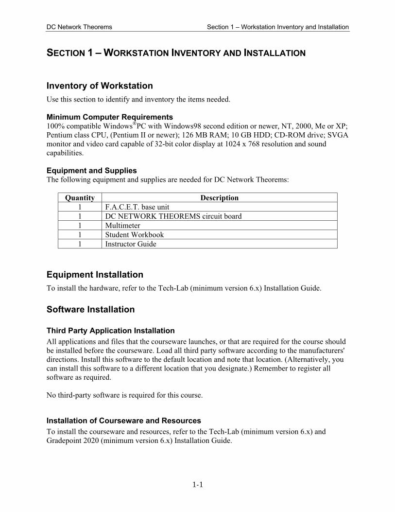
SECTION 1 – WORKSTATION INVENTORY AND INSTALLATION
Inventory of Workstation
Use this section to identify and inventory the items needed.
Minimum Computer Requirements 100% compatible Windows
®PC with Windows98 second edition or newer, NT, 2000, Me or XP;
Pentium class CPU, (Pentium II or newer); 126 MB RAM; 10 GB HDD; CD-ROM drive; SVGA
monitor and video card capable of 32-bit color display at 1024 x 768 resolution and sound
capabilities.
Equipment and Supplies The following equipment and supplies are needed for DC Network Theorems:
Quantity Description
1 F.A.C.E.T. base unit
1 DC NETWORK THEOREMS circuit board
1 Multimeter
1 Student Workbook
1 Instructor Guide
Equipment Installation
To install the hardware, refer to the Tech-Lab (minimum version 6.x) Installation Guide.
Software Installation
Third Party Application Installation
All applications and files that the courseware launches, or that are required for the course should
be installed before the courseware. Load all third party software according to the manufacturers'
directions. Install this software to the default location and note that location. (Alternatively, you
can install this software to a different location that you designate.) Remember to register all
software as required.
No third-party software is required for this course.
Installation of Courseware and Resources
To install the courseware and resources, refer to the Tech-Lab (minimum version 6.x) and
Gradepoint 2020 (minimum version 6.x) Installation Guide.

DC Network Theorems Section 1 – Workstation Inventory and Installation
1-2

SECTION 2 – INTRODUCTION TO F.A.C.E.T.
CURRICULUM

THIS
DC Network Theorems Section 2 – Introduction to F.A.C.E.T. Curriculum
2-1
SECTION 2 – INTRODUCTION TO F.A.C.E.T. CURRICULUM
Overview F.A.C.E.T. curriculum is multimedia-based courseware. The curriculum gives students hands-on
experience using equipment and software closely associated with industry standards. It provides
students with opportunities for instruction in academic and technical skills.
All courses are activity-driven curricula. Each course consists of several units containing two or
more exercises. Each unit begins with a statement explaining the overall goal of the unit (Unit
Objective). This is followed by Unit Fundamentals. Next is a list of new terms and words then
the equipment required for the unit. The exercises follow the unit material. When students
complete all the exercises, they complete the Troubleshooting section and take the Unit Test.
The exercises consist of an exercise objective, exercise discussion, and exercise procedures. The
Exercise Conclusions section provides the students with a list of their achievements. Every
exercise concludes with Review Questions. Available circuit modifications (CMs) and faults are
listed after the review questions. Additional specific information on CMs and faults is available
in Appendix B.

DC Network Theorems Section 2 – Introduction to F.A.C.E.T. Curriculum
2-2
Getting Started
Desktop
After the Tech-Lab System is installed, the TechLab icon appears on the desktop.
1. Click on the TechLab icon.
2. The student clicks on LOGON and selects his or her name.
3. The student enters his or her password and clicks on OK. (If he or she is creating a password,
four alphanumeric characters must be entered. The system will ask for the password to be
entered again for verification. Keep a record of the students' passwords.)
4. The previous two steps are repeated until all members of the student team have logged on.
Click on Complete and then Yes.
5. When the Available Courses menu appears, students click on the course name.
6. A window with the name of the course and a list of units for that course appears. Students
click on the unit name. The unit title page appears and the students are ready to begin.
Selecting Other Courses and Exiting the Courseware
1. Clicking on Exit when in a unit returns the student to the list of units for that course.
2. If students wish to select another unit, they click on it.
3. If students wish to exit F.A.C.E.T., they click on the X symbol in the upper right corner.
4. If students wish to select another course, they click on the Course Menu button. The
Available Courses menu screen appears. They may also exit F.A.C.E.T. from this screen by
clicking on the LOGOFF button.
DC Network Theorems Section 2 – Introduction to F.A.C.E.T. Curriculum
2-3
Screen Buttons
If you click on the F.A.C.E.T. logo on the top right of the unit title page the About screen
appears. It acknowledges the copyright holder(s) of video and/or screen-capture material used in
the topic.
The Menu button calls these menus:
when on an exercise menu screen, it calls the Unit Menu.
when on an exercise screen, it calls the Exercise Menu.
when on a unit screen, it calls the Unit Menu.
The Bookmark button marks the current screen. A student can click on the button at any time in
the lesson. The second time the student clicks on the button, the page displayed when the button
was first clicked will return to the screen. Any bookmarks used during a lesson are not saved
when the student logs out of the lesson.
The Application Launch button opens third-party software.
Click on the Resources button to view a pop-up menu. The pop-up menu includes access to a
calculator, a student journal, new terms and words, a print current screen option, the Lab-Volt
authored Internet Website, and a variety of F.A.C.E.T. help screens.
The Help button aids students with system information. On certain screens the Help button
appears to be depressed. On these screens, clicking on the Help button will access Screen Help
windows (context-sensitive help).
The Internet button opens an Internet browser. Students will have unrestricted access to all
search engines and web sites unless the school administration has restricted this usage.
Use the Exit button to exit the course.
The right arrow ⇒ button moves you forward to the next screen.
The left arrow ⇐ button moves you backward to the previous screen.
DC Network Theorems Section 2 – Introduction to F.A.C.E.T. Curriculum
2-4
F.A.C.E.T. Help Screens and Resources
There are three ways to access F.A.C.E.T. help screens and other resources.
System Help Students access System Help by clicking on the Help button at the bottom of the screen when the
button does not appear to be depressed. The menu selections access a variety of system help,
navigation, and information windows.
Screen Help On certain screens, the Help button appears to be depressed. On these screens, clicking on the
Help button will access Screen Help windows. This is information specific to the content of that
particular screen.
Resources Students click on the Resources button to access the following windows.
Calculator
F.A.C.E.T. 32-Bit Microprocessor Help
F.A.C.E.T. Analog Communications Setup Procedure
F.A.C.E.T. Digital Communications Help
F.A.C.E.T. Electronics and Troubleshooting Help
F.A.C.E.T. Fiber Optic Communications Help
F.A.C.E.T. Math Help
Internet Link
New Terms and Words
Print Current Page
Student Journal
DC Network Theorems Section 2 – Introduction to F.A.C.E.T. Curriculum
2-5
Internet Access
There are two ways for students to access the Internet:
The Internet button opens an Internet browser. Students have unrestricted access to all search
engines and websites unless the school administration has restricted this usage.
The Resources button pops up a menu that includes access to the Lab-Volt authored Internet
website. If students wish to access this site when they are not in the lesson, then they must go to
http://learning.labvolt.com.
NOTE: The Lab-Volt Internet site does not have content-filtering
software to block access to objectionable or inappropriate
websites.
Instructor Annotation Tool
The annotation tool gives the instructor the ability to add comments or additional information
onscreen. Refer to the Tech-Lab and GradePoint 2020 Installation Guide for detailed
information.
Student Journal
The student journal is an online notebook that each student can access while they are logged into
TechLab. The journal allows students to share notes with other students in their workgroups.
When used in conjunction with GradePoint 2020, the instructor may post messages, review, edit,
or delete any journal note.

DC Network Theorems Section 2 – Introduction to F.A.C.E.T. Curriculum
2-6
Assessing Progress
Assessment Tools
Student assessment is achieved in several ways:
♦ Exercise questions
♦ Unit tests
♦ Pretest and Posttest
♦ Troubleshooting questions
Exercise and Troubleshooting Questions
Throughout the unit material, exercise discussion, exercise procedure, and troubleshooting
sections there are several types of questions with instant feedback. These questions occur in the
following formats:
♦ Multiple choice
♦ True-false
♦ Real-number entry
In most cases, when your students encounter a question set, they must answer these questions
before continuing. However, there are cases where students may progress to the next screen
without answering the questions. Lab-Volt recommends that you encourage your students to
complete all questions. In this way, students reinforce the material that's presented, verify that
they understand this material, and are empowered to decide if a review of this material is
required.
Review Questions
At the end of each exercise, there are review questions. The student receives feedback with each
entry. Feedback guides the student toward the correct answer.
Unit Tests
A unit test appears at the end of each unit. The test consists of 10 multiple-choice questions with
the option of having feedback. The Tech-Lab System defaults to no feedback, but the instructor
can configure the test so that students receive feedback after taking the test. You can randomize
questions in the unit test. Use the Tech-Lab Global Configurator to make feedback available,
randomize questions, and select other configuration options if desired. Refer to the Tech Lab
Quick-Start Guide for detailed information.

DC Network Theorems Section 2 – Introduction to F.A.C.E.T. Curriculum
2-7
Pretest and Posttest
Every course includes a pretest and a posttest. These are multiple choice tests. Refer to the Tech
Lab Quick-Start Guide for detailed information on how to record student competency gains.
Grading
Student grades are based on exercise questions, troubleshooting questions, a unit test, and a
posttest. The default weighting value of the unit test and the threshold for passing the unit test
can be adjusted by using the Global Configurator of the Tech-Lab System. Refer to the Tech Lab
Quick-Start Guide for detailed information.
Student Progress and Instructor Feedback
Unit progress is available through the Unit menu. The Progress window allows the instructor and
student to view the percentage of the unit completed, number of sessions, and time spent on that
unit. The Progress window shows whether the Unit Test was completed. If the test was
completed, it indicates whether the student passed based on the scoring criteria.
DC Network Theorems Section 2 – Introduction to F.A.C.E.T. Curriculum
2-8
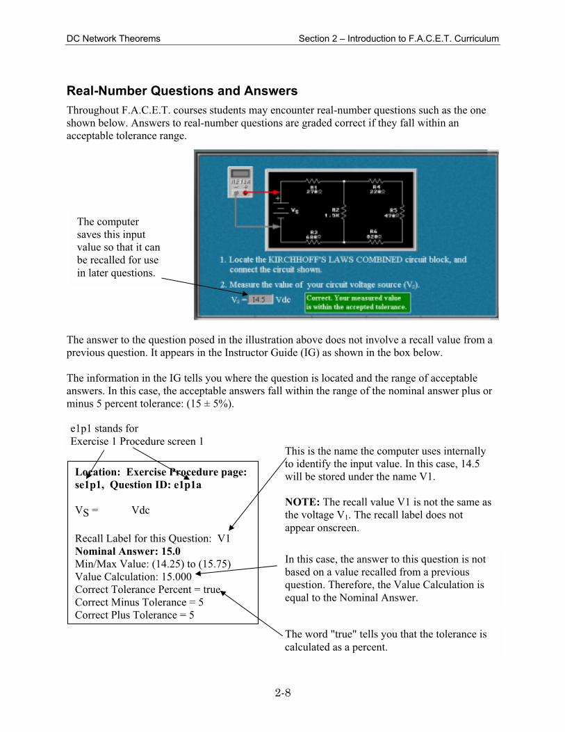
Real-Number Questions and Answers
Throughout F.A.C.E.T. courses students may encounter real-number questions such as the one
shown below. Answers to real-number questions are graded correct if they fall within an
acceptable tolerance range.
The answer to the question posed in the illustration above does not involve a recall value from a
previous question. It appears in the Instructor Guide (IG) as shown in the box below.
The information in the IG tells you where the question is located and the range of acceptable
answers. In this case, the acceptable answers fall within the range of the nominal answer plus or
minus 5 percent tolerance: (15 ± 5%).
Location: Exercise Procedure page:
se1p1, Question ID: e1p1a
VS = Vdc
Recall Label for this Question: V1
Nominal Answer: 15.0
Min/Max Value: (14.25) to (15.75)
Value Calculation: 15.000
Correct Tolerance Percent = true
Correct Minus Tolerance = 5
Correct Plus Tolerance = 5
This is the name the computer uses internally
to identify the input value. In this case, 14.5
will be stored under the name V1.
NOTE: The recall value V1 is not the same as
the voltage V1. The recall label does not
appear onscreen.
In this case, the answer to this question is not
based on a value recalled from a previous
question. Therefore, the Value Calculation is
equal to the Nominal Answer.
The word "true" tells you that the tolerance is
calculated as a percent.
e1p1 stands for
Exercise 1 Procedure screen 1
The computer
saves this input
value so that it can
be recalled for use
in later questions.

DC Network Theorems Section 2 – Introduction to F.A.C.E.T. Curriculum
2-9
A second example (shown below) illustrates an answer that the computer grades using a value
recalled from a previous question.
When a real-number question is based on a recall value from a previous question, the Min/Max
Value shown in the Instructor Guide is based upon a calculation using the lowest and highest
possible recall value. It represents the theoretical range of answers that could be accepted by the
computer. (It is not the nominal answer plus or minus the tolerance.)
To find the actual range of answers that the computer will accept onscreen, you must use the
actual recall value (14.5 in this example) in your calculations; see below.
NOTE: After four incorrect answers, students will be prompted to press <Ins> to insert the
correct answer if this feature has been enabled in the configuration settings. When the question is
based on a value recalled from a previous question, answers obtained using the Insert key may
not match the nominal answers in this guide.
Location: Exercise Procedure page:
se1p5, Question ID: e1p5c
IT = mA
Recall Label for this Question: I1
Nominal Answer: 9.091 *Min/Max Value: (6.477) to (11.93)
Value Calculation: #V1#/1650*1000
Correct Tolerance Percent = true
Correct Minus Tolerance = 25
Correct Plus Tolerance = 25
Since the value for #V1# is 14.5, the
computer will accept answers in the
following range as correct:
14.5/1650*1000 ± 25% or
8.79 ± 25% or
6.59 to 10.99
This calculated range is different from the
Min/Max Value shown in the IG, which
was based upon a calculation using the
lowest and highest possible recall value.
Any letter enclosed in "#" signs refers to a
recall value from a previous question.
DC Network Theorems Section 2 – Introduction to F.A.C.E.T. Curriculum
2-10
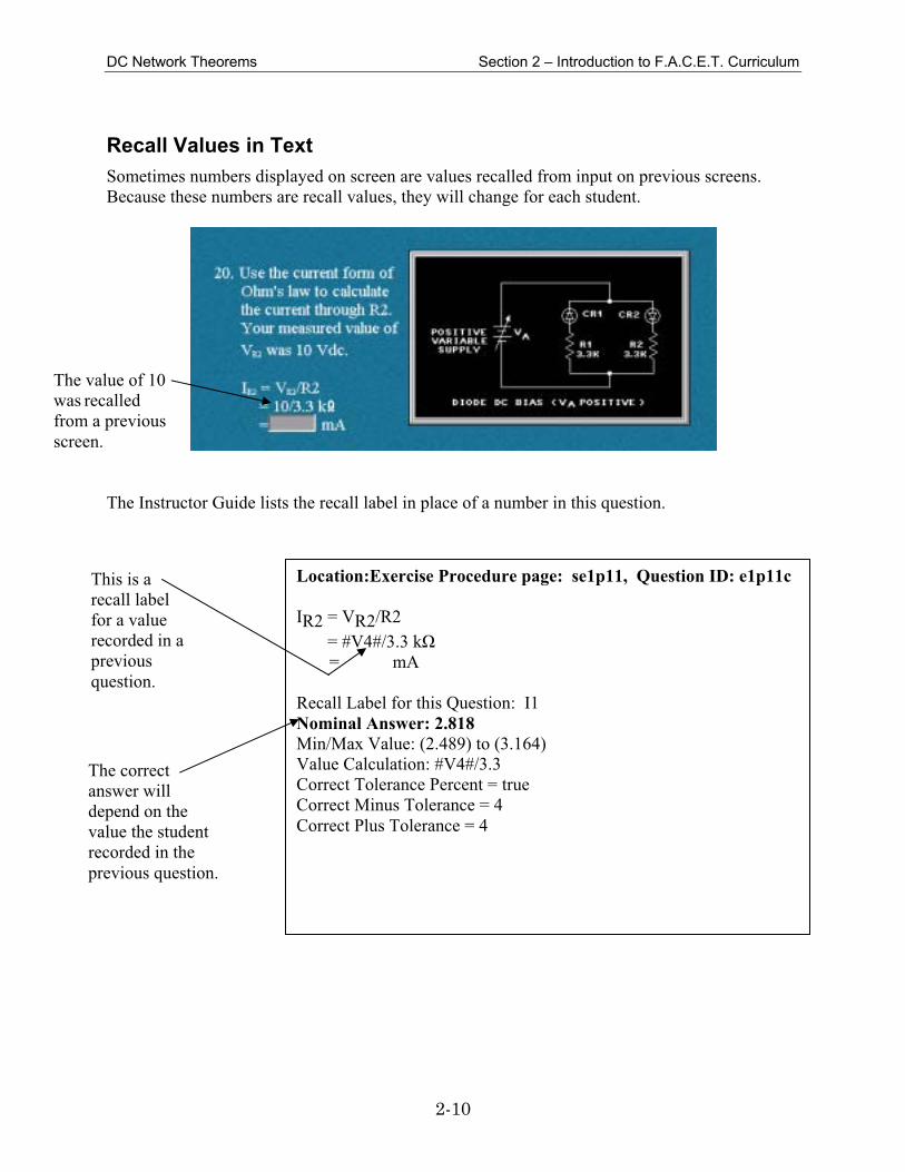
Recall Values in Text
Sometimes numbers displayed on screen are values recalled from input on previous screens.
Because these numbers are recall values, they will change for each student.
The Instructor Guide lists the recall label in place of a number in this question.
The value of 10
was recalled
from a previous
screen.
Location:Exercise Procedure page: se1p11, Question ID: e1p11c
IR2 = VR2/R2
= #V4#/3.3 kΩ
= mA
Recall Label for this Question: I1
Nominal Answer: 2.818
Min/Max Value: (2.489) to (3.164)
Value Calculation: #V4#/3.3
Correct Tolerance Percent = true
Correct Minus Tolerance = 4
Correct Plus Tolerance = 4
This is a
recall label
for a value
recorded in a
previous
question.
The correct
answer will
depend on the
value the student
recorded in the
previous question.
DC Network Theorems Section 2 – Introduction to F.A.C.E.T. Curriculum
2-11
Safety
Safety is everyone’s responsibility. All must cooperate to create the safest possible working
environment. Students must be reminded of the potential for harm, given common sense safety
rules, and instructed to follow the electrical safety rules.
Any environment can be hazardous when it is unfamiliar. The F.A.C.E.T. computer-based
laboratory may be a new environment to some students. Instruct students in the proper use of the
F.A.C.E.T. equipment and explain what behavior is expected of them in this laboratory. It is up
to the instructor to provide the necessary introduction to the learning environment and the
equipment. This task will prevent injury to both student and equipment.
The voltage and current used in the F.A.C.E.T. Computer-Based Laboratory are, in themselves,
harmless to the normal, healthy person. However, an electrical shock coming as a surprise will
be uncomfortable and may cause a reaction that could create injury. The students should be made
aware of the following electrical safety rules.
1. Turn off the power before working on a circuit.
2. Always confirm that the circuit is wired correctly before turning on the power. If required,
have your instructor check your circuit wiring.
3. Perform the experiments as you are instructed: do not deviate from the documentation.
4. Never touch “live” wires with your bare hands or with tools.
5. Always hold test leads by their insulated areas.
6. Be aware that some components can become very hot during operation. (However, this is not
a normal condition for your F.A.C.E.T. course equipment.) Always allow time for the
components to cool before proceeding to touch or remove them from the circuit.
7. Do not work without supervision. Be sure someone is nearby to shut off the power and
provide first aid in case of an accident.
8. Remove power cords by the plug, not by pulling on the cord. Check for cracked or broken
insulation on the cord.

DC Network Theorems Section 2 – Introduction to F.A.C.E.T. Curriculum
2-12

SECTION 3 – COURSEWARE
SECTION 3 – COURSEWARE

THIS
DC Network Theorems Unit 1 – DC Network Theorems
3-1
UNIT 1 – DC NETWORK THEOREMS
UNIT OBJECTIVE
Locate and identify the major components on the DC NETWORK THEOREMS circuit board.
UNIT FUNDAMENTALS
Location: Unit Fundamentals page: sf3, Question ID: f3a
On what circuit block is the current source used?
a. THEVENIN CIRCUITS circuit block
b. THEVENIN/NORTON CONVERSION circuit block
c. SUPERPOSITION circuit block
CMS AVAILABLE
None
FAULTS AVAILABLE
None
NEW TERMS AND WORDS
constant current source - a circuit designed to provide a fixed current that does not vary with
changes in load.
theorems - statements or methods that propose verifiable solutions of voltage and/or current
within a network.
networks - groups of components that form interrelated circuits.
EQUIPMENT REQUIRED
F.A.C.E.T. base unit
DC NETWORK THEOREMS circuit board
Multimeter
DC Network Theorems Unit 1 – DC Network Theorems
3-2
Exercise 1 – Component Location/Identification
EXERCISE OBJECTIVE
Locate the major circuit blocks of the DC NETWORK THEOREMS circuit board. Verify results
by correctly identifying circuits and components.
EXERCISE DISCUSSION
Location: Exercise Discussion page: se1d3, Question ID: e1d3a
Find the ∆ TO Y or Y TO ∆ (DELTA TO WYE or WYE TO DELTA) circuit block on the DC
NETWORK THEOREMS circuit board. Is power required for this block?
a. yes
b. no
EXERCISE PROCEDURE
Location: Exercise Procedure page: se1p1, Question ID: e1p1a
1. Locate the KIRCHHOFF'S CURRENT LAW circuit block. The resistors in this circuit can be
configured in
a. series.
b. parallel.
c. series/parallel.
Location: Exercise Procedure page: se1p2, Question ID: e1p2a
R1 = kΩ
Recall Label for this Question: None
Nominal Answer: 1.8
Min/Max Value: (1.8) to (1.8)
Value Calculation: 1.800
Correct Tolerance Percent = true
Correct Minus Tolerance = 0
Correct Plus Tolerance = 0
DC Network Theorems Unit 1 – DC Network Theorems
3-3
Location: Exercise Procedure page: se1p3, Question ID: e1p3a
3. The resistors used on the KIRCHHOFF'S VOLTAGE LAW circuit block are connected in
a. series.
b. parallel.
c. series/parallel.
Location: Exercise Procedure page: se1p4, Question ID: e1p4a
4. Which circuit block is configured with resistors connected as shown?
a. KIRCHHOFF'S VOLTAGE LAW circuit block
b. KIRCHHOFF'S CUR RENT LAW circuit block
c. THEVENIZING A BRIDGE CIRCUIT circuit block
Location: Exercise Procedure page: se1p5, Question ID: e1p5a
5. How many circuit blocks use fixed voltage sources?
a. 3
b. 4
c. 5
d. All of the circuit blocks use a fixed voltage source.
Location: Exercise Procedure page: se1p6, Question ID: e1p6a
6. Locate the THEVENIZING A BRIDGE CIRCUIT circuit block. What multimeter
measurements can you make for R5?
a. current
b. voltage
c. resistance
d. Any of the above.
Location: Exercise Procedure page: se1p7, Question ID: e1p7a
7. How many different types of networks are there in the ∆ TO Y or Y TO ∆ (DELTA TO WYE
or WYE TO DELTA) circuit block?
a. 2
b. 3
c. 4
Location: Exercise Procedure page: se1p8, Question ID: e1p8a
8. What does this symbol on the THEVENIN/NORTON CONVERSION circuit block represent?
a. a current source
b. a voltage source
c. total resistance
DC Network Theorems Unit 1 – DC Network Theorems
3-4
Location: Exercise Procedure page: se1p9, Question ID: e1p9a
9. This resistor configuration is a
a. T network.
b. Y network.
c. π network.
d. DELTA network.
Location: Exercise Procedure page: se1p10, Question ID: e1p10a
10. What F.A.C.E.T. component must you use to connect R3 of the SUPERPOSITION circuit
block to its power sources?
a. a terminal post
b. an interconnecting lead
c. a two-post connector
REVIEW QUESTIONS
Location: Review Questions page: se1r1, Question ID: e1r1
1. How many Kirchhoff's circuit blocks are on the circuit board?
a. 2
b. 3
c. 4
d. 5
Location: Review Questions page: se1r2, Question ID: e1r2
2. The symbol similar to this one on the THEVENIN/NORTON CONVERSION circuit block
represents a
a. constant current source.
b. constant voltage source.
c. variable current source.
d. None of the above.
Location: Review Questions page: se1r3, Question ID: e1r3
3. With two-post connectors inserted as shown here,
a. both power sources supply power to the network.
b. V2 is the only power source in the network.
c. V1 can be used to cancel the effect of V2.
d. current does not flow in the network.
DC Network Theorems Unit 1 – DC Network Theorems
3-5
Location: Review Questions page: se1r4, Question ID: e1r4
4. This circuit is located in the
a. SUPERPOSITION circuit block.
b. KIRCHHOFF'S CURRENT LAW circuit block.
c. THEVENIN CIRCUITS circuit block.
d. THEVENIN/NORTON CONVERSION circuit block.
Location: Review Questions page: se1r5, Question ID: e1r5
5. If you connect a multimeter across points A and D of the T NETWORK circuit block, what
are you measuring?
a. resistance of R1 and R2
b. voltage drop of R1 and R2
c. current through R1 and R2
d. resistance or voltage drop of R1 and R2
CMS AVAILABLE
None
FAULTS AVAILABLE
None
DC Network Theorems Unit 1 – DC Network Theorems
3-6
Exercise 2 – Circuit Board Operation
EXERCISE OBJECTIVE
Connect the various circuit blocks on the circuit board by using the KIRCHHOFF'S CURRENT
LAW circuit block as an example. Verify results with a multimeter.
EXERCISE DISCUSSION
Location: Exercise Discussion page: se2d2, Question ID: e2d2a
What determines the circuit configuration of the KIRCHHOFF'S CURRENT LAW circuit block
with respect to R1, R2, and the power supply?
a. test leads
b. terminal posts
c. two-post connectors
EXERCISE PROCEDURE
Location: Exercise Procedure page: se2p2, Question ID: e2p2a
VS = Vdc
Recall Label for this Question: None
Nominal Answer: 15.0
Min/Max Value: (14.55) to (15.45)
Value Calculation: 15.000
Correct Tolerance Percent = true
Correct Minus Tolerance = 3
Correct Plus Tolerance = 3
Location: Exercise Procedure page: se2p2, Question ID: e2p2c
R1 = Ω
Recall Label for this Question: None
Nominal Answer: 1800.0
Min/Max Value: (1440) to (2160)
Value Calculation: 1800.000
Correct Tolerance Percent = true
Correct Minus Tolerance = 20
Correct Plus Tolerance = 20
DC Network Theorems Unit 1 – DC Network Theorems
3-7
Location: Exercise Procedure page: se2p2, Question ID: e2p2e
R2 = Ω
Recall Label for this Question: None
Nominal Answer: 2200.0
Min/Max Value: (1760) to (2640)
Value Calculation: 2200.000
Correct Tolerance Percent = true
Correct Minus Tolerance = 20
Correct Plus Tolerance = 20
Location: Exercise Procedure page: se2p3, Question ID: e2p3a
4. What should the voltage drop across R1 or R2 be?
a. the same as VS
b. 0V
Location: Exercise Procedure page: se2p4, Question ID: e2p4a
VR1 or VR2 = Vdc
Recall Label for this Question: None
Nominal Answer: 0.0
Min/Max Value: (0) to (0)
Value Calculation: 0.000
Correct Tolerance Percent = true
Correct Minus Tolerance = 0
Correct Plus Tolerance = 0
Location: Exercise Procedure page: se2p4, Question ID: e2p4c
6. Do your measurements indicate an open path to R1 or R2?
a. yes
b. no
Location: Exercise Procedure page: se2p4, Question ID: e2p4e
IR1 = mA
Recall Label for this Question: None
Nominal Answer: 8.3
Min/Max Value: (6.225) to (10.38)
Value Calculation: 8.300
Correct Tolerance Percent = true
Correct Minus Tolerance = 25
Correct Plus Tolerance = 25

DC Network Theorems Unit 1 – DC Network Theorems
3-8
Location: Exercise Procedure page: se2p4, Question ID: e2p4g
8. Why does current flow through R1?
a. because a two-post connector was added at VS
b. because a current meter was added at R1
Location: Exercise Procedure page: se2p4, Question ID: e2p4i
9. With the present test circuit connections, does current flow through R2?
a. yes
b. no
Location: Exercise Procedure page: se2p5, Question ID: e2p5a
10. How can you cause current to flow through R2?
a. Place a two-post connector at the top of R2.
b. Connect a current meter at the top of R2.
c. Either of the above.
REVIEW QUESTIONS
Location: Review Questions page: se2r1, Question ID: e2r1
1. Measure total circuit current by removing the two-post connector and replacing it with a meter
in position
a. A.
b. B.
c. C.
d. D.
Location: Review Questions page: se2r2, Question ID: e2r2
2. Measure total circuit voltage by placing a meter in position
a. A.
b. B.
c. C.
d. D.
Location: Review Questions page: se2r3, Question ID: e2r3
3. The meter in position C (with the two-post connector removed) indicates
a. maximum circuit current.
b. R1 current.
c. R2 current.
d. the combined current of R1 and R2.
DC Network Theorems Unit 1 – DC Network Theorems
3-9
Location: Review Questions page: se2r4, Question ID: e2r4
4. Measure the voltage drop of R1 or R2 with a meter placed in position
a. A.
b. B.
c. C.
d. D.
Location: Review Questions page: se2r5, Question ID: e2r5
5. For this circuit, how many two-post connectors are required to obtain maximum circuit
current?
a. 4
b. 3
c. 2
d. 1
CMS AVAILABLE
None
FAULTS AVAILABLE
None
DC Network Theorems Unit 1 – DC Network Theorems
3-10
UNIT TEST
Depending on configurator settings, these questions may be randomized onscreen.
Location: Unit Test Question page: sut1, Question ID: ut1
The measurement(s) required on the DC NETWORK THEOREMS circuit board is (are)
a. voltage.
b. voltage and current.
c. voltage, current, or resistance.
d. resistance.
Location: Unit Test Question page: sut2, Question ID: ut2
The current source required in the THEVENIN/NORTON CONVERSION circuit block
a. must be externally supplied.
b. is available on the circuit board.
c. is student adjustable.
d. generates a constant voltage.
Location: Unit Test Question page: sut3, Question ID: ut3
A network is a group of components that
a. are not related.
b. are exactly the same.
c. share a common circuit.
d. are in series.
Location: Unit Test Question page: sut4, Question ID: ut4
Constant current sources
a. have very low output impedances.
b. vary the amount of current generated when the load changes.
c. cannot be operated into open circuits.
d. are load independent.
Location: Unit Test Question page: sut5, Question ID: ut5
Network theorems are required because
a. Ohm's law cannot easily be applied to all circuits.
b. Ohms law can easily be applied to all circuits.
c. circuits will not operate without them.
d. Ohm's law cannot provide reliable results in series/parallel circuits.
DC Network Theorems Unit 1 – DC Network Theorems
3-11
Location: Unit Test Question page: sut6, Question ID: ut6
The 3 resistor types on the circuit board
a. have equal tolerances.
b. can be distinguished by color code values.
c. are carbon composition, carbon film, and metal film types.
d. have equal power dissipation ratings.
Location: Unit Test Question page: sut7, Question ID: ut7
On the DC NETWORK THEOREMS circuit board, which type of power source is used?
a. fixed voltage source
b. variable voltage source
c. fixed and variable voltage sources
d. no voltage sources
Location: Unit Test Question page: sut8, Question ID: ut8
Which of the following should be used to configure branches within the circuit blocks of the DC
NETWORK THEOREMS circuit board?
a. two-post connectors
b. solid wire jumpers
c. terminal posts
d. None of the above.
Location: Unit Test Question page: sut9, Question ID: ut9
When you measure resistance on the DC NETWORK THEOREMS circuit board,
a. circuit power should be maximum.
b. circuit power should be disconnected.
c. circuit power should be minimum.
d. meter polarity is important.
Location: Unit Test Question page: sut10, Question ID: ut10
When you measure voltage or current on the DC NETWORK THEOREMS circuit board,
a. meter polarity does not matter.
b. voltage polarity is the same for any meter connection.
c. current flow through a circuit changes direction with an improper meter connection.
d. meter polarity determines the "correctness" of the indication.

DC Network Theorems Unit 1 – DC Network Theorems
3-12

DC Network Theorems Unit 2 – Kirchhoff’s Current Law
3-13
UNIT 2 – KIRCHHOFF’S CURRENT LAW
UNIT OBJECTIVE
Analyze dc circuits by using Kirchhoff's current law.
UNIT FUNDAMENTALS
Location: Unit Fundamentals page: sf2, Question ID: f2a
What does the total circuit current equal?
a. sum of both branch currents (CURRENT 1 + CURRENT 2)
b. current through either branch (CURRENT 1 or CURRENT 2)
Location: Unit Fundamentals page: sf3, Question ID: f3a
Total circuit current is the current through branch
a. R1.
b. R2.
c. R1 and branch R2.
Location: Unit Fundamentals page: sf4, Question ID: f4a
How many branches are there at each node in this parallel branch circuit?
a. 1
b. 2
c. 3
CMS AVAILABLE
None
FAULTS AVAILABLE
None

DC Network Theorems Unit 2 – Kirchhoff’s Current Law
3-14
NEW TERMS AND WORDS
Kirchhoff's current law - the algebraic sum of the currents at any node must equal zero.
junction - a circuit point where components are joined.
parallel branch - a circuit loop through which a part of the total circuit current flows.
nodes - circuit points where Kirchhoff's current law can be applied; also called junctions.
junction - a circuit point where components are joined.
algebraic sum - a combination of positive and negative values based on the rules of algebra.
EQUIPMENT REQUIRED
F.A.C.E.T. base unit
DC NETWORK THEOREMS circuit board
Multimeter
DC Network Theorems Unit 2 – Kirchhoff’s Current Law
3-15
Exercise 1 – Current in a Branch Circuit
EXERCISE OBJECTIVE
Calculate total and individual branch currents in a two-element parallel circuit by using
Kirchhoff's current law. Verify results by measuring the circuit currents
EXERCISE DISCUSSION
No Questions
EXERCISE PROCEDURE
Location: Exercise Procedure page: se1p1, Question ID: e1p1a
VS = Vdc
Recall Label for this Question: v1
Nominal Answer: 15.0
Min/Max Value: (14.55) to (15.45)
Value Calculation: 15.000
Correct Tolerance Percent = true
Correct Minus Tolerance = 3
Correct Plus Tolerance = 3
Location: Exercise Procedure page: se1p2, Question ID: e1p2a
R1 = Ω
Recall Label for this Question: None
Nominal Answer: 1800.0
Min/Max Value: (1800) to (1800)
Value Calculation: 1800.000
Correct Tolerance Percent = true
Correct Minus Tolerance = 0
Correct Plus Tolerance = 0

DC Network Theorems Unit 2 – Kirchhoff’s Current Law
3-16
Location: Exercise Procedure page: se1p2, Question ID: e1p2c
R2 = Ω
Recall Label for this Question: None
Nominal Answer: 2200.0
Min/Max Value: (2200) to (2200)
Value Calculation: 2200.000
Correct Tolerance Percent = true
Correct Minus Tolerance = 0
Correct Plus Tolerance = 0
Location: Exercise Procedure page: se1p3, Question ID: e1p3a
IR1 = mA
Recall Label for this Question: i1
Nominal Answer: 8.333 ∗Min/Max Value: (7.275) to (9.442)
Value Calculation: (#v1#/1800)*1000
Correct Tolerance Percent = true
Correct Minus Tolerance = 10
Correct Plus Tolerance = 10
Location: Exercise Procedure page: se1p3, Question ID: e1p3c
IR2 = mA
Recall Label for this Question: i2
Nominal Answer: 6.818 *Min/Max Value: (5.952) to (7.725)
Value Calculation: (#v1#/2200)*1000
Correct Tolerance Percent = true
Correct Minus Tolerance = 10
Correct Plus Tolerance = 10
∗ NOTE: Min/Max Values shown are based upon a calculation using the absolute
lowest and highest recall value. By using the actual input in your calculations, you
will determine the correct value.

DC Network Theorems Unit 2 – Kirchhoff’s Current Law
3-17
Location: Exercise Procedure page: se1p4, Question ID: e1p4a
IT = mA
Recall Label for this Question: i3
Nominal Answer: 15.15 ∗Min/Max Value: (11.9 ) to (18.88)
Value Calculation: #i1#+#i2#
Correct Tolerance Percent = true
Correct Minus Tolerance = 10
Correct Plus Tolerance = 10
Location: Exercise Procedure page: se1p5, Question ID: e1p5a
IR1 = mA
Recall Label for this Question: i4
Nominal Answer: 8.33
Min/Max Value: (6.664) to (9.996)
Value Calculation: 8.330
Correct Tolerance Percent = true
Correct Minus Tolerance = 20
Correct Plus Tolerance = 20
Location: Exercise Procedure page: se1p5, Question ID: e1p5c
IR2 = mA
Recall Label for this Question: i5
Nominal Answer: 6.82
Min/Max Value: (5.456) to (8.184)
Value Calculation: 6.820
Correct Tolerance Percent = true
Correct Minus Tolerance = 20
Correct Plus Tolerance = 20
∗ NOTE: Min/Max Values shown are based upon a calculation using the absolute
lowest and highest recall value. By using the actual input in your calculations, you
will determine the correct value.
DC Network Theorems Unit 2 – Kirchhoff’s Current Law
3-18
Location: Exercise Procedure page: se1p5, Question ID: e1p5e
IT = mA
Recall Label for this Question: i6
Nominal Answer: 15.15 ∗Min/Max Value: (11.51) to (19.09)
Value Calculation: #i4#+#i5#
Correct Tolerance Percent = true
Correct Minus Tolerance = 5
Correct Plus Tolerance = 5
Location: Exercise Procedure page: se1p6, Question ID: e1p6a
11. Do your calculated and measured values agree within tolerance?
a. yes
b. no
Location: Exercise Procedure page: se1p7, Question ID: e1p7a
IR1 = mA
Recall Label for this Question: None
Nominal Answer: 8.332 *Min/Max Value: (4.05 ) to (13.32)
Value Calculation: (#i3#–#i2#)
Correct Tolerance Percent = true
Correct Minus Tolerance = 3
Correct Plus Tolerance = 3
Location: Exercise Procedure page: se1p8, Question ID: e1p8a
13. Does Kirchhoff's current law support the results you obtained from Ohm's law?
a. no
b. yes
∗ NOTE: Min/Max Values shown are based upon a calculation using the absolute
lowest and highest recall value. By using the actual input in your calculations, you
will determine the correct value.
DC Network Theorems Unit 2 – Kirchhoff’s Current Law
3-19
REVIEW QUESTIONS
Location: Review Questions page: se1r1, Question ID: e1r1a
IT = mA
Recall Label for this Question: r1i1
Nominal Answer: 19.0
Min/Max Value: (15.2) to (22.8)
Value Calculation: 19.000
Correct Tolerance Percent = true
Correct Minus Tolerance = 20
Correct Plus Tolerance = 20
Location: Review Questions page: se1r1, Question ID: e1r1
If IR2 is 6.8 mA, what is the value of IR1?
a. 25.8 mA
b. # r1i1 – 6.8 # mA
c. 6.8 mA
d. 1.22 mA
Location: Review Questions page: se1r2, Question ID: e1r2
2. If IR1 is # r1i1 – 6.8 # mA (with CM 1 activated) and the source voltage (VS) is 15.00 Vdc,
what is the present value of R1 in this circuit?
a. approximately 12.0 kΩ b. 15 / # ( r1i1 – 6.8 )# Ω c. approximately 12Ω
d. cannot be determined
Location: Review Questions page: se1r3, Question ID: e1r3
3. If the CM switch decreases the value of R1, total circuit current
a. changes, but the branch currents remain the same.
b. and both branch currents change.
c. decreases while IR2 does not change.
d. increases while IR2 does not change.

DC Network Theorems Unit 2 – Kirchhoff’s Current Law
3-20
Location: Review Questions page: se1r4, Question ID: e1r4
4. The branch currents of this circuit
a. should be added to determine total current.
b. should be subtracted to determine total current.
c. are not correct because of the circuit modification.
d. do not equal the total circuit current.
Location: Review Questions page: se1r5, Question ID: e1r5
5. If a third branch (R3) were added to the circuit, what would be the total circuit current?
a. IR1 + IR2 – IR3
b. IR1 + IR2 + IT
c. IR1 + IR2 + IR3
d. cannot be determined
CMS AVAILABLE
CM 1
CM 1 TOGGLE
FAULTS AVAILABLE
None

DC Network Theorems Unit 2 – Kirchhoff’s Current Law
3-21
Exercise 2 – Node Currents in a Branch Circuit
EXERCISE OBJECTIVE
Determine the magnitude and direction (sign) of node currents by using a two-element branch
circuit. Verify results by measuring the circuit currents.
EXERCISE DISCUSSION
Location: Exercise Discussion page: se2d1, Question ID: e2d1a
Another way to state Kirchhoff's current law is that when all of the node currents are combined,
the total positive current must equal
a. zero.
b. half the negative current.
c. the total negative current.
Location: Exercise Discussion page: se2d2, Question ID: e2d2a
How much more current must flow out of the node to satisfy Kirchhoff's current law?
a. 1.0A
b. 1.5A
c. 2.5A

DC Network Theorems Unit 2 – Kirchhoff’s Current Law
3-22
EXERCISE PROCEDURE
Location: Exercise Procedure page: se2p1, Question ID: e2p1a
VS = Vdc
Recall Label for this Question: v2
Nominal Answer: 15.0
Min/Max Value: (14.25) to (15.75)
Value Calculation: 15.000
Correct Tolerance Percent = true
Correct Minus Tolerance = 5
Correct Plus Tolerance = 5
Location: Exercise Procedure page: se2p2, Question ID: e2p2a
IR1 = mA
Recall Label for this Question: i7
Nominal Answer: 8.333 ∗Min/Max Value: (7.521) to (9.188)
Value Calculation: (#v2#/1800)*1000
Correct Tolerance Percent = true
Correct Minus Tolerance = 5
Correct Plus Tolerance = 5
Location: Exercise Procedure page: se2p2, Question ID: e2p2c
IR2 = mA
Recall Label for this Question: i8
Nominal Answer: 6.818 *Min/Max Value: (6.153) to (7.517)
Value Calculation: (#v2#/2200)*1000
Correct Tolerance Percent = true
Correct Minus Tolerance = 5
Correct Plus Tolerance = 5
∗ NOTE: Min/Max Values shown are based upon a calculation using the absolute
lowest and highest recall value. By using the actual input in your calculations, you
will determine the correct value.
DC Network Theorems Unit 2 – Kirchhoff’s Current Law
3-23
Location: Exercise Procedure page: se2p2, Question ID: e2p2e
IT (Kirchhoff's) = mA
Recall Label for this Question: i9
Nominal Answer: 15.15 ∗Min/Max Value: (12.99) to (17.54)
Value Calculation: #i7#+#i8#
Correct Tolerance Percent = true
Correct Minus Tolerance = 5
Correct Plus Tolerance = 5
Location: Exercise Procedure page: se2p2, Question ID: e2p2g
6. Based on your results, is the current entering the circuit node equal to the current leaving the
circuit node?
a. yes
b. no
Location: Exercise Procedure page: se2p3, Question ID: e2p3a
IT (calculated) = mA
Recall Label for this Question: i10
Nominal Answer: 15.15 *Min/Max Value: (13.67) to (16.7 )
Value Calculation: (.00101*#v2#)*1000
Correct Tolerance Percent = true
Correct Minus Tolerance = 5
Correct Plus Tolerance = 5
Location: Exercise Procedure page: se2p4, Question ID: e2p4a
8. Does the answer you calculated agree with the total current determined by Kirchhoff's current
law?
a. yes
b. no
∗ NOTE: Min/Max Values shown are based upon a calculation using the absolute
lowest and highest recall value. By using the actual input in your calculations, you
will determine the correct value.
DC Network Theorems Unit 2 – Kirchhoff’s Current Law
3-24
REVIEW QUESTIONS
Location: Review Questions page: se2r1, Question ID: e2r1a
IR2 = mA
Recall Label for this Question: None
Nominal Answer: 6.8
Min/Max Value: (6.12) to (7.48)
Value Calculation: 6.800
Correct Tolerance Percent = true
Correct Minus Tolerance = 10
Correct Plus Tolerance = 10
Location: Review Questions page: se2r1, Question ID: e2r1
The current out of the node
a. increases.
b. remains the same.
c. decreases.
d. None of the above.
Location: Review Questions page: se2r2, Question ID: e2r2
2. With CM 2 still activated, the value of R2 is
a. 1.1 kΩ.
b. 2.2 kΩ.
c. 4.4 kΩ.
d. cannot be determined.
Location: Review Questions page: se2r3, Question ID: e2r3
3. Total circuit current (IT) is 11.7 mA, and IR1 is 8.32 mA. What is the value of IR2?
a. 20.02 mA
b. 3.38 mA
c. 8.32 mA
d. cannot be determined
Location: Review Questions page: se2r4, Question ID: e2r4
4. When the resistance of R2 decreases, the node current
a. increases.
b. remains the same.
c. decreases.
d. None of the above.

DC Network Theorems Unit 2 – Kirchhoff’s Current Law
3-25
Location: Review Questions page: se2r5, Question ID: e2r5
5. Kirchhoff's current law, as applied to parallel circuits such as this one, states that
a. IT, IR1, and IR2 are not related because of a common power source.
b. VS must not change if either VR1 or VR2 changes.
c. the currents of NODE 1 and NODE 2 need not be equal.
d. the currents of NODE 1 and NODE 2 must be equal.
CMS AVAILABLE
CM 2 TOGGLE
CM 2
FAULTS AVAILABLE
None
DC Network Theorems Unit 2 – Kirchhoff’s Current Law
3-26
UNIT TEST
Depending on configurator settings, these questions may be randomized onscreen.
Location: Unit Test Question page: sut1, Question ID: ut1
In this circuit, total circuit current (IT)
a. cannot be determined.
b. equals the current of either circuit node.
c. equals the sum of the branch currents.
d. does not change if node current changes.
Location: Unit Test Question page: sut2, Question ID: ut2
Which statement defines the current out of NODE 1?
a. IR1 + IR2 + IR3
b. IR2 + IR3
c. IT – (IR2 + IR3)
d. IT + (IR2 + IR3)
Location: Unit Test Question page: sut3, Question ID: ut3
Which statement defines the current into NODE 2?
a. IR1 + IR2 + IR3
b. IT – IR1
c. IT – (IR2 + IR3)
d. IT + (IR2 + IR3)
Location: Unit Test Question page: sut4, Question ID: ut4
Which statement defines the current out of NODE 2?
a. IR1 + IR2 + IR3
b. IR2 + IR3
c. IT – (IR2 + IR3)
d. IT + (IR2 + IR3)
Location: Unit Test Question page: sut5, Question ID: ut5
In this circuit, IT enters NODE 1. What part of IT does not go through NODE 2?
a. IR3
b. IR2
c. IR1
d. None of the above.
DC Network Theorems Unit 2 – Kirchhoff’s Current Law
3-27
Location: Unit Test Question page: sut6, Question ID: ut6
The current through NODE 2 is
a. greater than the current through NODE 1.
b. less than the current through NODE 1.
c. equal to the current through NODE 1.
d. equal to the current from the power source.
Location: Unit Test Question page: sut7, Question ID: ut7
In this circuit, the respective branch currents are
a. 10 mA, 5 mA, and 5 mA.
b. 5 mA, 10 mA, and 10 mA.
c. 10 mA, 5 mA, and 10 mA.
d. 10 mA, 10 mA, and 10 mA.
Location: Unit Test Question page: sut8, Question ID: ut8
If R2 in this circuit increases in value, IR2 decreases and NODE 1 current
a. increases.
b. does not change.
c. decreases.
d. cannot be determined unless the amount of increase in R2 is specified.
Location: Unit Test Question page: sut9, Question ID: ut9
Using Ohm's law and/or Kirchhoff's current law for parallel circuits, IT in this circuit
a. cannot be determined.
b. is 5 mA.
c. is 10 mA.
d. is 20 mA.
Location: Unit Test Question page: sut10, Question ID: ut10
The current into NODE 2 is 10 mA; therefore, current out of NODE 2
a. must be less than 10 mA.
b. must be greater than 10 mA.
c. must be 10 mA.
d. cannot be determined.

DC Network Theorems Unit 2 – Kirchhoff’s Current Law
3-28
TROUBLESHOOTING
Location: Troubleshooting page: ttrba2, Question ID: trba2a
IT = mA
Recall Label for this Question: it
Nominal Answer: 15.15
Min/Max Value: (13.64) to (16.67)
Value Calculation: 15.150
Correct Tolerance Percent = true
Correct Minus Tolerance = 10
Correct Plus Tolerance = 10
Location: Troubleshooting page: ttrba3, Question ID: trba3a
3. Does the total current (#it# mA) equal the sum of the branch currents?
a. yes
b. no
Location: Troubleshooting page: ttrba4, Question ID: trba4a
4. Does the voltage across each branch equal the source voltage?
a. no
b. yes
Location: Troubleshooting page: ttrba5, Question ID: trba5
6. The faulty component is
a. VS1 (out of specification).
b. R1 (lower than specified minimum value).
c. R2 (lower than specified minimum value).
d. R1 (open).
CMS AVAILABLE
None
FAULTS AVAILABLE
Fault 1
DC Network Theorems Unit 3 – Kirchhoff’s Voltage Law
3-29
UNIT 3 – KIRCHHOFF’S VOLTAGE LAW
UNIT OBJECTIVE
Analyze dc circuits by using Kirchhoff's voltage law.
UNIT FUNDAMENTALS
Location: Unit Fundamentals page: sf2, Question ID: f2a
The circuit current (IT) in this closed series circuit is
a. different in each circuit element.
b. common to each circuit element.
Location: Unit Fundamentals page: sf5, Question ID: f5a
How may Kirchhoff's voltage law be stated?
a. The sum of all the voltage drops in a series circuit equals the circuit applied (source) voltage.
b. The algebraic sum of the voltage source(s) and voltage drops in a series circuit equals zero.
c. Both of the above.
Location: Unit Fundamentals page: sf7, Question ID: f7a
In this circuit, if the source voltage is 9V and two of the voltage drops are 4V and 3V, what is the
third drop?
a. 1V
b. 2V
c. 7V
CMS AVAILABLE
None
FAULTS AVAILABLE
None
DC Network Theorems Unit 3 – Kirchhoff’s Voltage Law
3-30
NEW TERMS AND WORDS
Kirchhoff's voltage law - The algebraic sum of the voltages around a closed loop must equal
zero. The sum of the voltage drops around a closed loop must equal the source voltage.
closed loop - A complete path or circuit for current flow.
EQUIPMENT REQUIRED
F.A.C.E.T. base unit
DC NETWORK THEOREMS circuit board
Multimeter

DC Network Theorems Unit 3 – Kirchhoff’s Voltage Law
3-31
Exercise 1 – 3-Element Series Voltages
EXERCISE OBJECTIVE
Calculate total voltage and individual voltage drops by using a 3-element series circuit. Verify
results with a multimeter.
EXERCISE DISCUSSION
Location: Exercise Discussion page: se1d5, Question ID: e1d5a
Can you use Kirchhoff's voltage law for any number of elements in a series circuit?
a. yes
b. no
EXERCISE PROCEDURE
Location: Exercise Procedure page: se1p1, Question ID: e1p1a
VS = Vdc
Recall Label for this Question: V1
Nominal Answer: 15.0
Min/Max Value: (14.25) to (15.75)
Value Calculation: 15.000
Correct Tolerance Percent = true
Correct Minus Tolerance = 5
Correct Plus Tolerance = 5
DC Network Theorems Unit 3 – Kirchhoff’s Voltage Law
3-32
Location: Exercise Procedure page: se1p1, Question ID: e1p1c
IT = mA
Recall Label for this Question: I1
Nominal Answer: 10.14 ∗Min/Max Value: (9.34 ) to (10.96)
Value Calculation: # ( V1 / 1480 ) * 1000 #
Correct Tolerance Percent = true
Correct Minus Tolerance = 3
Correct Plus Tolerance = 3
Location: Exercise Procedure page: se1p2, Question ID: e1p2a
VR1 = Vdc
Recall Label for this Question: V2
Nominal Answer: 2.231 *Min/Max Value: (1.952) to (2.532)
Value Calculation: # ( I1 * 220 ) / 1000 #
Correct Tolerance Percent = true
Correct Minus Tolerance = 5
Correct Plus Tolerance = 5
Location: Exercise Procedure page: se1p2, Question ID: e1p2c
VR2 = Vdc
Recall Label for this Question: V3
Nominal Answer: 5.171 *Min/Max Value: (4.525) to (5.869)
Value Calculation: # ( I1 * 510 ) / 1000 #
Correct Tolerance Percent = true
Correct Minus Tolerance = 5
Correct Plus Tolerance = 5
∗ NOTE: Min/Max Values shown are based upon a calculation using the absolute
lowest and highest recall value. By using the actual input in your calculations, you
will determine the correct value.

DC Network Theorems Unit 3 – Kirchhoff’s Voltage Law
3-33
Location: Exercise Procedure page: se1p2, Question ID: e1p2e
VR3 = Vdc
Recall Label for this Question: V4
Nominal Answer: 7.605 ∗Min/Max Value: (6.655) to (8.631)
Value Calculation: # ( I1 * 750 ) / 1000 #
Correct Tolerance Percent = true
Correct Minus Tolerance = 5
Correct Plus Tolerance = 5
Location: Exercise Procedure page: se1p3, Question ID: e1p3a
Do your results prove that the sum of the voltage drops about equals the source voltage
(VS #V1# Vdc)?
a. yes
b. no
Location: Exercise Procedure page: se1p3, Question ID: e1p3c
8. Do your results indicate that Ohm's law and Kirchhoff's voltage law can be applied for a
circuit solution?
a. no
b. yes
Location: Exercise Procedure page: se1p4, Question ID: e1p4a
Based on this equation, which formula can you use to calculate the value of VR2?
a. VR2 = VS – VR1 – VR3
b. VR2 = VS – (VR1 + VR3)
c. Either of the above.
∗ NOTE: Min/Max Values shown are based upon a calculation using the absolute
lowest and highest recall value. By using the actual input in your calculations, you
will determine the correct value.
DC Network Theorems Unit 3 – Kirchhoff’s Voltage Law
3-34
Location: Exercise Procedure page: se1p4, Question ID: e1p4c
VR2 (calculated) = Vdc
Recall Label for this Question: V5
Nominal Answer: 5.164 ∗Min/Max Value: (2.933) to (7.5 )
Value Calculation: # V1 – V2 – V4 #
Correct Tolerance Percent = true
Correct Minus Tolerance = 5
Correct Plus Tolerance = 5
Location: Exercise Procedure page: se1p5, Question ID: e1p5a
VR2 (measured) = Vdc
Recall Label for this Question: V6
Nominal Answer: 5.171 *Min/Max Value: (4.073) to (6.456)
Value Calculation: #V3#
Correct Tolerance Percent = true
Correct Minus Tolerance = 10
Correct Plus Tolerance = 10
Location: Exercise Procedure page: se1p6, Question ID: e1p6a
12. Does your measured value agree with your calculated results, within tolerance?
a. no
b. yes
Location: Exercise Procedure page: se1p7, Question ID: e1p7a
VR1 = Vdc
Recall Label for this Question: V7
Nominal Answer: 2.231 *Min/Max Value: (1.849) to (2.652)
Value Calculation: # ( I1 * 220 ) / 1000 #
Correct Tolerance Percent = true
Correct Minus Tolerance = 10
Correct Plus Tolerance = 10
∗ NOTE: Min/Max Values shown are based upon a calculation using the absolute
lowest and highest recall value. By using the actual input in your calculations, you
will determine the correct value.

DC Network Theorems Unit 3 – Kirchhoff’s Voltage Law
3-35
Location: Exercise Procedure page: se1p7, Question ID: e1p7c
VR2 = Vdc
Recall Label for this Question: None
Nominal Answer: 5.171 ∗Min/Max Value: (3.666) to (7.102)
Value Calculation: #V6#
Correct Tolerance Percent = true
Correct Minus Tolerance = 10
Correct Plus Tolerance = 10
Location: Exercise Procedure page: se1p7, Question ID: e1p7e
VR3 = Vdc
Recall Label for this Question: V8
Nominal Answer: 7.605 *Min/Max Value: (6.305) to (9.042)
Value Calculation: # ( I1 * 750) / 1000 #
Correct Tolerance Percent = true
Correct Minus Tolerance = 10
Correct Plus Tolerance = 10
Location: Exercise Procedure page: se1p8, Question ID: e1p8a
14. Does the sum of your measured voltage drops equal the value of your circuit voltage source?
a. no
b. yes
∗ NOTE: Min/Max Values shown are based upon a calculation using the absolute
lowest and highest recall value. By using the actual input in your calculations, you
will determine the correct value.
DC Network Theorems Unit 3 – Kirchhoff’s Voltage Law
3-36
REVIEW QUESTIONS
Location: Review Questions page: se1r1, Question ID: e1r1
Based on Kirchhoff's voltage law, the sum of the voltage drops
a. is greater than the source voltage.
b. does not change because the source voltage does not change.
c. is less than the source voltage.
d. can no longer be determined.
Location: Review Questions page: se1r2, Question ID: e1r2
Based on Kirchhoff's law, the sum of the voltage drops
a. is greater than the source voltage.
b. does not change because the source voltage does not change.
c. is less than the source voltage.
d. can no longer be determined.
Location: Review Questions page: se1r3, Question ID: e1r3
3. When you change the value of R3, the sum of the voltage drops does not change because the
source voltage
a. increases.
b. does not change.
c. decreases.
d. None of the above.
Location: Review Questions page: se1r4, Question ID: e1r4
4. Using Kirchhoff's law, what is the voltage drop across R2 (VR2)?
a. 15V
b. 10V
c. 5V
d. cannot be determined
Location: Review Questions page: se1r5, Question ID: e1r5
5. Which statement correctly uses Kirchhoff's voltage law to explain this circuit?
a. VS = VR1 – VR2 + VR3 + VR4
b. VS = VR2 – (VR1 + VR3 + VR4)
c. VS = VS + VR2 – (VR1 + VR3 + VR4)
d. VS = VR1 + VR2 + VR3 + VR4

DC Network Theorems Unit 3 – Kirchhoff’s Voltage Law
3-37
CMS AVAILABLE
CM 4 TOGGLE
CM 3 TOGGLE
FAULTS AVAILABLE
None
DC Network Theorems Unit 3 – Kirchhoff’s Voltage Law
3-38
Exercise 2 – Algebraic Sum of Series Voltages
EXERCISE OBJECTIVE
Calculate the algebraic sum of voltage drops by using a 3-element series circuit. Verify results
with a multimeter.
EXERCISE DISCUSSION
Location: Exercise Discussion page: se2d4, Question ID: e2d4a
In this circuit, which equation is correct for determining VR1?
a. VR1 = VS – VR2 – VR3
b. VR1 = VS – (VR2 + VR3)
c. Neither a. nor b.
d. Both a. and b.
EXERCISE PROCEDURE
Location: Exercise Procedure page: se2p1, Question ID: e2p1a
VS = Vdc
Recall Label for this Question: V21
Nominal Answer: 15.0
Min/Max Value: (14.55) to (15.45)
Value Calculation: 15.000
Correct Tolerance Percent = true
Correct Minus Tolerance = 3
Correct Plus Tolerance = 3
DC Network Theorems Unit 3 – Kirchhoff’s Voltage Law
3-39
Location: Exercise Procedure page: se2p2, Question ID: e2p2a
VR1 = Vdc
Recall Label for this Question: V22
Nominal Answer: –2.23 ∗Min/Max Value: (–2.53) to (–1.94)
Value Calculation: –# ( V21 / 1480 ) * 220 #
Correct Tolerance Percent = true
Correct Minus Tolerance = 10
Correct Plus Tolerance = 10
Location: Exercise Procedure page: se2p2, Question ID: e2p2c
VR2 = Vdc
Recall Label for this Question: V23
Nominal Answer: –5.17 *Min/Max Value: (–5.86) to (–4.51)
Value Calculation: –# ( V21 / 1480 ) * 510 #
Correct Tolerance Percent = true
Correct Minus Tolerance = 10
Correct Plus Tolerance = 10
Location: Exercise Procedure page: se2p2, Question ID: e2p2e
VR3 = Vdc
Recall Label for this Question: V24
Nominal Answer: –7.601 *Min/Max Value: (–8.61) to (–6.64)
Value Calculation: –# ( V21 / 1480 ) * 750 #
Correct Tolerance Percent = true
Correct Minus Tolerance = 10
Correct Plus Tolerance = 10
∗ NOTE: Min/Max Values shown are based upon a calculation using the absolute
lowest and highest recall value. By using the actual input in your calculations, you
will determine the correct value.

DC Network Theorems Unit 3 – Kirchhoff’s Voltage Law
3-40
Location: Exercise Procedure page: se2p3, Question ID: e2p3a
VR1 + VR2 + VR3 = Vdc
Recall Label for this Question: V25
Nominal Answer: –15.0 ∗Min/Max Value: (–17. ) to (–13.01)
Value Calculation: # V21 * –1 #
Correct Tolerance Percent = true
Correct Minus Tolerance = 10
Correct Plus Tolerance = 10
Location: Exercise Procedure page: se2p4, Question ID: e2p4a
Your result is closest to
a. 0.0 Vdc.
b. 15.00 Vdc.
c. 30.00 Vdc.
REVIEW QUESTIONS
Location: Review Questions page: se2r1, Question ID: e2r1
CM 3 is now activated to decrease the resistance of R2. What is the sum of the circuit voltage
drops?
a. 20V
b. 15V
c. 10V
d. None of the above.
Location: Review Questions page: se2r2, Question ID: e2r2
2. By applying Ohm's law and Kirchhoff's voltage law to this circuit, you determine that the
approximate value of R2 is
a. 44,200Ω.
b. 4420Ω.
c. 442Ω.
d. not changed by the circuit modification.
∗ NOTE: Min/Max Values shown are based upon a calculation using the absolute
lowest and highest recall value. By using the actual input in your calculations, you
will determine the correct value.
DC Network Theorems Unit 3 – Kirchhoff’s Voltage Law
3-41
Location: Review Questions page: se2r3, Question ID: e2r3
3. The polarity of the voltage source in your circuit
a. should be the same as that of the voltage drops.
b. cannot be determined.
c. should be opposite to that of the voltage drops.
d. is not needed for an algebraic summation.
Location: Review Questions page: se2r4, Question ID: e2r4
4. In this circuit, what is the value of R1?
a. 1 kΩ b. 10 kΩ c. 3 kΩ d. Cannot be determined.
Location: Review Questions page: se2r5, Question ID: e2r5
5. In this circuit, what is the voltage drop of R2?
a. 50 Vdc
b. 25 Vdc
c. 15 Vdc
d. 10 Vdc
CMS AVAILABLE
None
FAULTS AVAILABLE
None
DC Network Theorems Unit 3 – Kirchhoff’s Voltage Law
3-42
UNIT TEST
Depending on configurator settings, these questions may be randomized onscreen.
Location: Unit Test Question page: sut1, Question ID: ut1
In a closed loop such as this one, Kirchhoff's voltage law states that the sum of the voltage drops
a. must be greater than the circuit source voltage.
b. must equal the circuit source voltage.
c. must be less than the circuit source voltage.
d. cannot be determined unless circuit current is known.
Location: Unit Test Question page: sut2, Question ID: ut2
In a closed loop such as this one, Kirchhoff's voltage law states that the circuit source voltage
a. must be greater than the sum of the voltage drops.
b. must equal the sum of the voltage drops.
c. must be less than the sum of the voltage drops.
d. cannot be determined unless circuit current is known.
Location: Unit Test Question page: sut3, Question ID: ut3
In a closed loop, the algebraic sum of the circuit voltages
a. cannot be determined without circuit current.
b. must not equal zero if current flows in the loop.
c. varies depending on the source voltage.
d. equals zero for any value of source voltage.
Location: Unit Test Question page: sut4, Question ID: ut4
Which equation defines Kirchhoff's voltage law?
a. VS = VR1 + VR2
b. 0 = VS – (VR1 + VR2)
c. Both of the above.
d. None of the above.
Location: Unit Test Question page: sut5, Question ID: ut5
A series circuit consists of 3 elements and a voltage source. If the source voltage and the voltage
drops of 2 elements are known, the voltage drop of the third element
a. cannot be determined.
b. is zero.
c. can be determined from Kirchhoff's voltage law.
d. must equal the voltage drop of the other elements.

DC Network Theorems Unit 3 – Kirchhoff’s Voltage Law
3-43
Location: Unit Test Question page: sut6, Question ID: ut6
Kirchhoff's voltage law proves that
a. Ohm's law is not accurate for series circuits.
b. Ohm's law can define the operation of a series circuit.
c. current and resistance cannot be used to determine a voltage drop.
d. None of the above.
Location: Unit Test Question page: sut7, Question ID: ut7
If your calculations indicate that the algebraic sum of the voltages in your circuit is greater or
less than zero,
a. modify the circuit.
b. increase the voltage source.
c. decrease the voltage source.
d. check your calculations.
Location: Unit Test Question page: sut8, Question ID: ut8
In order for you to apply Kirchhoff's voltage law to a circuit, the source voltage
a. must be zero.
b. must be positive.
c. must be negative.
d. may be positive or negative.
Location: Unit Test Question page: sut9, Question ID: ut9
What is the value of each element?
a. 0.5Ω b. 1Ω c. 1.5Ω d. None of the above.
Location: Unit Test Question page: sut10, Question ID: ut10
In this circuit, the source voltage is doubled. Based on Kirchhoff's voltage law,
a. the sum of the voltage drops must increase.
b. the sum of the voltage drops does not change.
c. the sum of the voltage drops must decrease.
d. more resistance must be added to the circuit.
DC Network Theorems Unit 3 – Kirchhoff’s Voltage Law
3-44
TROUBLESHOOTING
Location: Troubleshooting page: ttrba2, Question ID: trba2a
IT = mA
Recall Label for this Question: None
Nominal Answer: 10.14
Min/Max Value: (9.126) to (11.15)
Value Calculation: 10.140
Correct Tolerance Percent = true
Correct Minus Tolerance = 10
Correct Plus Tolerance = 10
Location: Troubleshooting page: ttrba3, Question ID: trba3a
3. Does the sum of the voltage drops equal VS?
a. yes
b. no
Location: Troubleshooting page: ttrba4, Question ID: trba4a
4. Does the algebraic sum of the voltages equal zero?
a. yes
b. no
Location: Troubleshooting page: ttrba5, Question ID: trba5
6. The faulty component is
a. R1 (increased).
b. R2 (increased).
c. R2 (decreased).
d. R3 (decreased).
CMS AVAILABLE
None
FAULTS AVAILABLE
Fault 2
DC Network Theorems Unit 4 – Kirchhoff’s Loop Equations
3-45
UNIT 4 – KIRCHHOFF’S LOOP EQUATIONS
UNIT OBJECTIVE
Use loop equations by applying Kirchhoff's laws to a series/parallel circuit.
UNIT FUNDAMENTALS
Location: Unit Fundamentals page: sf2, Question ID: f2a
What is the loop equation for this loop?
a. VR1 + VRS = VS
b. VR2 + VRS = VS
Location: Unit Fundamentals page: sf3, Question ID: f3a
For Kirchhoff's current law, which basic node equation is correct?
a. Inode in = Inode out
b. Inode out – Inode in = 0
c. Both of the above.
CMS AVAILABLE
None
FAULTS AVAILABLE
None
NEW TERMS AND WORDS
None
EQUIPMENT REQUIRED
F.A.C.E.T. base unit
DC NETWORK THEOREMS circuit board
Multimeter

DC Network Theorems Unit 4 – Kirchhoff’s Loop Equations
3-46
Exercise 1 – Loop Equations
EXERCISE OBJECTIVE
Use loop equations for a series/parallel circuit. Verify results by measuring voltage drops and
calculating equations.
EXERCISE DISCUSSION
Location: Exercise Discussion page: se1d6, Question ID: e1d6a
Do the values show that Kirchhoff's voltage law for each loop equation is satisfied?
a. yes
b. no
Location: Exercise Discussion page: se1d7, Question ID: e1d7a
Do the voltage values applied to the loop equations still result in zero?
a. no
b. yes
EXERCISE PROCEDURE
Location: Exercise Procedure page: se1p1, Question ID: e1p1a
VS = Vdc
Recall Label for this Question: V1
Nominal Answer: 15.0
Min/Max Value: (14.25) to (15.75)
Value Calculation: 15.000
Correct Tolerance Percent = true
Correct Minus Tolerance = 5
Correct Plus Tolerance = 5
Location: Exercise Procedure page: se1p2, Question ID: e1p2a
The first loop includes
a. R3, R2, and R1.
b. R6, R5, and R4.
c. R3, R2, R1, and VS.
DC Network Theorems Unit 4 – Kirchhoff’s Loop Equations
3-47
Location: Exercise Procedure page: se1p3, Question ID: e1p3a
5. The second loop includes
a. R3, R2, and R1.
b. R6, R5, R4, and VS.
c. R6, R5, R4, and R2.
Location: Exercise Procedure page: se1p4, Question ID: e1p4a
7. The third loop includes
a. R3, R6, R5, R4, R1, and VS.
b. R3, R6, R5, R4, R2, and VS.
c. R3, R2, R5, and R1.
Location: Exercise Procedure page: se1p5, Question ID: e1p5a
9. All current from the voltage source goes out through R3 and returns through
a. R2.
b. R5.
c. R1.
Location: Exercise Procedure page: se1p5, Question ID: e1p5c
IT = mA
Recall Label for this Question: I1
Nominal Answer: 9.091 ∗Min/Max Value: (6.477) to (11.93)
Value Calculation: #V1#/1650*1000
Correct Tolerance Percent = true
Correct Minus Tolerance = 25
Correct Plus Tolerance = 25
∗ NOTE: Min/Max Values shown are based upon a calculation using the absolute
lowest and highest recall value. By using the actual input in your calculations, you
will determine the correct value.
DC Network Theorems Unit 4 – Kirchhoff’s Loop Equations
3-48
Location: Exercise Procedure page: se1p6, Question ID: e1p6a
VR1 = Vdc
Recall Label for this Question: V2
Nominal Answer: 2.455 ∗Min/Max Value: (1.574) to (3.543)
Value Calculation: #I1#*270/1000
Correct Tolerance Percent = true
Correct Minus Tolerance = 10
Correct Plus Tolerance = 10
Location: Exercise Procedure page: se1p6, Question ID: e1p6c
VR3 = Vdc
Recall Label for this Question: V3
Nominal Answer: 6.182 *Min/Max Value: (3.964) to (8.924)
Value Calculation: #I1#*680/1000
Correct Tolerance Percent = true
Correct Minus Tolerance = 10
Correct Plus Tolerance = 10
Location: Exercise Procedure page: se1p6, Question ID: e1p6e
13. Which loop equation can be used to determine VR2, based on Kirchhoff's law and the known
loop values?
a. VR2 = VS + VR1 + VR3
b. VR2 = VS – (VR1 + VR3)
c. VR2 = VS – (VR6 + VR4)
∗ NOTE: Min/Max Values shown are based upon a calculation using the absolute
lowest and highest recall value. By using the actual input in your calculations, you
will determine the correct value.
DC Network Theorems Unit 4 – Kirchhoff’s Loop Equations
3-49
Location: Exercise Procedure page: se1p6, Question ID: e1p6g
VR2 = VS – (VR1 + VR3)
= Vdc
Recall Label for this Question: V4
Nominal Answer: 6.363 ∗Min/Max Value: (1.605) to (11.23)
Value Calculation: # V1 – ( V2 + V3 ) #
Correct Tolerance Percent = true
Correct Minus Tolerance = 10
Correct Plus Tolerance = 10
Location: Exercise Procedure page: se1p7, Question ID: e1p7a
VR2 = Vdc
Recall Label for this Question: V5
Nominal Answer: 6.363 *Min/Max Value: (1.445) to (12.35)
Value Calculation: #V4#
Correct Tolerance Percent = true
Correct Minus Tolerance = 10
Correct Plus Tolerance = 10
Location: Exercise Procedure page: se1p7, Question ID: e1p7c
16. Are the calculated and measured values of VR2 the same within tolerance?
a. no
b. yes
∗ NOTE: Min/Max Values shown are based upon a calculation using the absolute
lowest and highest recall value. By using the actual input in your calculations, you
will determine the correct value.
DC Network Theorems Unit 4 – Kirchhoff’s Loop Equations
3-50
REVIEW QUESTIONS
Location: Review Questions page: se1r1, Question ID: e1r1a
VS = Vdc
Recall Label for this Question: VR1
Nominal Answer: 15.0
Min/Max Value: (14.25) to (15.75)
Value Calculation: 15.000
Correct Tolerance Percent = true
Correct Minus Tolerance = 5
Correct Plus Tolerance = 5
Location: Review Questions page: se1r1, Question ID: e1r1c
VR1 = Vdc
Recall Label for this Question: VR2
Nominal Answer: 1.9378 ∗Min/Max Value: (1.6568) to (2.2382)
Value Calculation: (#VR1#/2090)*270
Correct Tolerance Percent = true
Correct Minus Tolerance = 10
Correct Plus Tolerance = 10
Location: Review Questions page: se1r1, Question ID: e1r1e
VR2 = Vdc
Recall Label for this Question: VR3
Nominal Answer: 5.3
Min/Max Value: (4.77) to (5.83)
Value Calculation: 5.3
Correct Tolerance Percent = true
Correct Minus Tolerance = 10
Correct Plus Tolerance = 10
∗ NOTE: Min/Max Values shown are based upon a calculation using the absolute
lowest and highest recall value. By using the actual input in your calculations, you
will determine the correct value.
DC Network Theorems Unit 4 – Kirchhoff’s Loop Equations
3-51
Location: Review Questions page: se1r1, Question ID: e1r1
1. What is the new value of VR3 based on your measurements and the loop equation?
a. # VR1 – ( VR2 + VR3 )#V
b. #VR3#V
c. #VR2#V
d. cannot be determined
Location: Review Questions page: se1r2, Question ID: e1r2
What is the voltage across R5?
a. 2.5V
b. 3V
c. 7V
d. 8V
Location: Review Questions page: se1r3, Question ID: e1r3
Therefore, the voltage drops of R1 and R2
a. are not affected by the change in R3.
b. remain the same.
c. cannot be determined.
d. must change.
Location: Review Questions page: se1r4, Question ID: e1r4
4. What law(s) may you use to analyze the voltages within the loop composed of VS, R1, R2,
and R3?
a. Ohm's law
b. Kirchhoff's law
c. Both of the above.
d. None of the above.
Location: Review Questions page: se1r5, Question ID: e1r5
What is the polarity of R2?
a. negative at point A and positive at point B
b. positive at point A and negative at point B
c. negative at point A and at point B
d. positive at point A and at point B

DC Network Theorems Unit 4 – Kirchhoff’s Loop Equations
3-52
CMS AVAILABLE
CM 8 TOGGLE
FAULTS AVAILABLE
None

DC Network Theorems Unit 4 – Kirchhoff’s Loop Equations
3-53
Exercise 2 – Node Equations
EXERCISE OBJECTIVE
Generate node equations for a series/parallel circuit. Verify results by measuring voltage drops
and ensuring that the loop equations equal zero.
EXERCISE DISCUSSION
Location: Exercise Discussion page: se2d5, Question ID: e2d5a
In this circuit, if you know IT and I1, can you calculate I2?
a. yes
b. no
EXERCISE PROCEDURE
Location: Exercise Procedure page: se2p1, Question ID: e2p1a
VS = Vdc
Recall Label for this Question: V21
Nominal Answer: 15.0
Min/Max Value: (14.25) to (15.75)
Value Calculation: 15.000
Correct Tolerance Percent = true
Correct Minus Tolerance = 5
Correct Plus Tolerance = 5

DC Network Theorems Unit 4 – Kirchhoff’s Loop Equations
3-54
Location: Exercise Procedure page: se2p1, Question ID: e2p1c
VR3 = Vdc
Recall Label for this Question: V22
Nominal Answer: 5.993 ∗Min/Max Value: (5.124) to (6.922)
Value Calculation: (#V21#/1702)*680
Correct Tolerance Percent = true
Correct Minus Tolerance = 10
Correct Plus Tolerance = 10
Location: Exercise Procedure page: se2p1, Question ID: e2p1e
IT = mA
Recall Label for this Question: I21
Nominal Answer: 8.813 *Min/Max Value: (6.782) to (11.2 )
Value Calculation: (#V22#/680)*1000
Correct Tolerance Percent = true
Correct Minus Tolerance = 10
Correct Plus Tolerance = 10
Location: Exercise Procedure page: se2p2, Question ID: e2p2a
VR1 = Vdc
Recall Label for this Question: V23
Nominal Answer: 2.38 *Min/Max Value: (1.648) to (3.326)
Value Calculation: (#I21#*270)/1000
Correct Tolerance Percent = true
Correct Minus Tolerance = 10
Correct Plus Tolerance = 10
∗ NOTE: Min/Max Values shown are based upon a calculation using the absolute
lowest and highest recall value. By using the actual input in your calculations, you
will determine the correct value.
DC Network Theorems Unit 4 – Kirchhoff’s Loop Equations
3-55
Location: Exercise Procedure page: se2p2, Question ID: e2p2c
VR2 = Vdc
Recall Label for this Question: V24
Nominal Answer: 6.627 ∗Min/Max Value: (3.802) to (9.427)
Value Calculation: # V21 – ( V22 + V23 ) #
Correct Tolerance Percent = true
Correct Minus Tolerance = 5
Correct Plus Tolerance = 5
Location: Exercise Procedure page: se2p3, Question ID: e2p3a
5. Does the current flowing through R2 move into or out of NODE 2?
a. into NODE 2
b. out of NODE 2
Location: Exercise Procedure page: se2p4, Question ID: e2p4a
IR2 = mA
Recall Label for this Question: I22
Nominal Answer: 4.418 *Min/Max Value: (2.281) to (6.913)
Value Calculation: (#V24#/1500)*1000
Correct Tolerance Percent = true
Correct Minus Tolerance = 10
Correct Plus Tolerance = 10
Location: Exercise Procedure page: se2p4, Question ID: e2p4c
IR6 = mA
Recall Label for this Question: I23
Nominal Answer: 4.395 *Min/Max Value: ( –.14) to (9.365)
Value Calculation: #I21#–#I22#
Correct Tolerance Percent = true
Correct Minus Tolerance = 5
Correct Plus Tolerance = 5
∗ NOTE: Min/Max Values shown are based upon a calculation using the absolute
lowest and highest recall value. By using the actual input in your calculations, you
will determine the correct value.
DC Network Theorems Unit 4 – Kirchhoff’s Loop Equations
3-56
Location: Exercise Procedure page: se2p5, Question ID: e2p5a
8. Knowing IR6, can you use Ohm's law to determine the voltage drops of R6, R5, and R4?
a. no
b. yes
Location: Exercise Procedure page: se2p6, Question ID: e2p6a
VR6 = Vdc
Recall Label for this Question: V25
Nominal Answer: 3.604 ∗Min/Max Value: ( –.13) to (8.447)
Value Calculation: (#I23#*820)/1000
Correct Tolerance Percent = true
Correct Minus Tolerance = 10
Correct Plus Tolerance = 10
Location: Exercise Procedure page: se2p6, Question ID: e2p6c
VR5 = Vdc
Recall Label for this Question: V26
Nominal Answer: 2.066 *Min/Max Value: ( –.07) to (4.842)
Value Calculation: (#I23#*470)/1000
Correct Tolerance Percent = true
Correct Minus Tolerance = 10
Correct Plus Tolerance = 10
Location: Exercise Procedure page: se2p6, Question ID: e2p6e
VR4 = Vdc
Recall Label for this Question: V27
Nominal Answer: 0.967 *Min/Max Value: ( –.03) to (2.266)
Value Calculation: (#I23#*220)/1000
Correct Tolerance Percent = true
Correct Minus Tolerance = 10
Correct Plus Tolerance = 10
∗ NOTE: Min/Max Values shown are based upon a calculation using the absolute
lowest and highest recall value. By using the actual input in your calculations, you
will determine the correct value.

DC Network Theorems Unit 4 – Kirchhoff’s Loop Equations
3-57
Location: Exercise Procedure page: se2p7, Question ID: e2p7a
10. Does the sum of the voltages and VR2 result in 0V for the loop?
a. yes
b. no
Location: Exercise Procedure page: se2p8, Question ID: e2p8a
11. Based on your observation, can Kirchhoff's laws be combined with Ohm's law to solve for
unknowns in a series/parallel circuit?
a. no
b. yes
REVIEW QUESTIONS
Location: Review Questions page: se2r1, Question ID: e2r1
1. In this circuit, I1
a. moves into NODE 1.
b. moves out of NODE 1.
c. must be zero.
d. equals IT + I1.
Location: Review Questions page: se2r2, Question ID: e2r2
2. The current into NODE 2 equals
a. IT – I2.
b. IT + I1.
c. I1 + I2.
d. I2 + IT.
Location: Review Questions page: se2r3, Question ID: e2r3a
VR5 = Vdc
Recall Label for this Question: VR21
Nominal Answer: 2.07
Min/Max Value: (1.863) to (2.277)
Value Calculation: 2.070
Correct Tolerance Percent = true
Correct Minus Tolerance = 10
Correct Plus Tolerance = 10

DC Network Theorems Unit 4 – Kirchhoff’s Loop Equations
3-58
Location: Review Questions page: se2r3, Question ID: e2r3
3. The I2 current out of NODE 1
a. increases.
b. decreases.
c. remains the same.
d. None of the above.
Location: Review Questions page: se2r4, Question ID: e2r4
4. Since activating CM 9 increases I2, the I1 current out of NODE 1
a. increases.
b. does not change.
c. decreases.
d. None of the above.
Location: Review Questions page: se2r5, Question ID: e2r5
5. If the current flowing into a node is 180 mA, all of the current flowing out of the node, based
on Kirchhoff's law, is
a. less than 180 mA.
b. greater than 180 mA.
c. less or greater than 180 mA.
d. equal to 180 mA.
CMS AVAILABLE
CM 9 TOGGLE
FAULTS AVAILABLE
None
DC Network Theorems Unit 4 – Kirchhoff’s Loop Equations
3-59
UNIT TEST
Depending on configurator settings, these questions may be randomized onscreen.
Location: Unit Test Question page: sut1, Question ID: ut1
Which diagram correctly shows node current?
a. A
b. B
c. C
d. D
Location: Unit Test Question page: sut2, Question ID: ut2
A loop can be defined as
a. any circuit path, closed or opened.
b. a closed circuit path.
c. an open circuit path.
d. a voltage source.
Location: Unit Test Question page: sut3, Question ID: ut3
A node represents a circuit point where
a. voltages are combined.
b. resistances are combined.
c. currents are combined.
d. charge must accumulate.
Location: Unit Test Question page: sut4, Question ID: ut4
When you use Kirchhoff's laws, algebraic signs are
a. required.
b. not required.
c. required for voltage only.
d. required for current only.
Location: Unit Test Question page: sut5, Question ID: ut5
In this circuit, the
a. voltage drops are greater than the voltage source.
b. voltage drops are less than the voltage source.
c. given equation does not specify the circuit.
d. given equation specifies the circuit.
DC Network Theorems Unit 4 – Kirchhoff’s Loop Equations
3-60
Location: Unit Test Question page: sut6, Question ID: ut6
In this circuit, IB
a. flows out of NODE 1.
b. flows into NODE 1.
c. equals IT.
d. does not flow into NODE 2.
Location: Unit Test Question page: sut7, Question ID: ut7
In this circuit, IC
a. equals IB.
b. equals IA.
c. equals IT.
d. flows into NODE 2.
Location: Unit Test Question page: sut8, Question ID: ut8
The value of IB equals
a. IT + IA.
b. IT – IA.
c. IT.
d. IB + IA.
Location: Unit Test Question page: sut9, Question ID: ut9
The missing voltage is
a. 10V.
b. 5V.
c. 1V.
d. None of the above.
Location: Unit Test Question page: sut10, Question ID: ut10
The current through R3
a. can flow in either direction.
b. can flow in only one direction.
c. is zero because the circuit loops cancel.
d. is zero because the circuit loops combine.
DC Network Theorems Unit 4 – Kirchhoff’s Loop Equations
3-61
TROUBLESHOOTING
Location: Troubleshooting page: ttrba2, Question ID: trba2a
IT = mA
Recall Label for this Question: TSIT1
Nominal Answer: 8.81
Min/Max Value: (7.929) to (9.691)
Value Calculation: 8.810
Correct Tolerance Percent = true
Correct Minus Tolerance = 10
Correct Plus Tolerance = 10
Location: Troubleshooting page: ttrba2, Question ID: trba2c
VR2 = V
Recall Label for this Question: TSV1
Nominal Answer: 6.63
Min/Max Value: (5.967) to (7.293)
Value Calculation: 6.63
Correct Tolerance Percent = true
Correct Minus Tolerance = 10
Correct Plus Tolerance = 10
Location: Troubleshooting page: ttrba3, Question ID: trba3a
3. Does the total circuit current (#TSIT1# mA) flow through R2?
a. yes
b. no
Location: Troubleshooting page: ttrba4, Question ID: trba4a
4. Does the sum of VR3, VR2, and VR1 equal VS?
a. yes
b. no
Location: Troubleshooting page: ttrba5, Question ID: trba5
6. The faulty component is
a. R1 (shorted).
b. R2 (open).
c. R4 (shorted).
d. R6 (increased).

DC Network Theorems Unit 4 – Kirchhoff’s Loop Equations
3-62
Location: Troubleshooting page: ttrbb2, Question ID: trbb2a
IT = mA
Recall Label for this Question: TSIT2
Nominal Answer: 8.81
Min/Max Value: (7.929) to (9.691)
Value Calculation: 8.810
Correct Tolerance Percent = true
Correct Minus Tolerance = 10
Correct Plus Tolerance = 10
Location: Troubleshooting page: ttrbb2, Question ID: trbb2c
VR2 = V
Recall Label for this Question: TSV2
Nominal Answer: 6.63
Min/Max Value: (5.967) to (7.293)
Value Calculation: 6.63
Correct Tolerance Percent = true
Correct Minus Tolerance = 10
Correct Plus Tolerance = 10
Location: Troubleshooting page: ttrbb3, Question ID: trbb3
4. The faulty component is
a. R1 (shorted).
b. R2 (open).
c. R4 (shorted).
d. R6 (increased).
CMS AVAILABLE
None
FAULTS AVAILABLE
Fault 4
Fault 6
DC Network Theorems Unit 5 – Kirchhoff’s Solution with 2 Sources
3-63
UNIT 5 – KIRCHHOFF’S SOLUTION WITH 2 SOURCES
UNIT OBJECTIVE
Find voltage and current in circuits with two voltage sources by using Kirchhoff's laws. Verify
results by comparing measured and calculated values.
UNIT FUNDAMENTALS
Location: Unit Fundamentals page: sf2, Question ID: f2a
If you make an incorrect assumption, what can you do to make the circuit solution correct?
a. Recalculate the currents.
b. Reverse the direction of assumed current flow through R3.
Location: Unit Fundamentals page: sf3, Question ID: f3a
How many nodes are in this circuit?
a. 1
b. 2
c. 3
Location: Unit Fundamentals page: sf8, Question ID: f8a
Can you check the solutions generated by these methods by ensuring that the voltage drops
and/or currents follow Kirchhoff's laws?
a. no
b. yes
CMS AVAILABLE
None
FAULTS AVAILABLE
None

DC Network Theorems Unit 5 – Kirchhoff’s Solution with 2 Sources
3-64
NEW TERMS AND WORDS
nodes - common connections for two or more components.
mesh - a single closed path without any branches.
mesh equations - equations that define the current within a mesh
loop equations - equations that define the voltage drops around a closed loop.
EQUIPMENT REQUIRED
F.A.C.E.T. base unit
DC NETWORK THEOREMS circuit board
Multimeter
DC Network Theorems Unit 5 – Kirchhoff’s Solution with 2 Sources
3-65
Exercise 1 – Kirchhoff's Voltage Law/2 Sources
EXERCISE OBJECTIVE
Apply Kirchhoff's voltage law to a circuit having two voltage sources. Verify results by using
measured data.
EXERCISE DISCUSSION
Location: Exercise Discussion page: se1d2, Question ID: e1d2a
What is the third loop composed of?
a. VS1, R3, and R1
b. VS2, R3, and R2
c. VS1, R1, R2, and VS2
Location: Exercise Discussion page: se1d3, Question ID: e1d3a
What is the LOOP 2 equation?
a. VS1 – VR3 – VR1 = 0
b. VS2 – VR2 + VR3 = 0
DC Network Theorems Unit 5 – Kirchhoff’s Solution with 2 Sources
3-66
EXERCISE PROCEDURE
Location: Exercise Procedure page: se1p1, Question ID: e1p1a
VS1 = Vdc
Recall Label for this Question: v1
Nominal Answer: 10.0
Min/Max Value: (9.7) to (10.3)
Value Calculation: 10.000
Correct Tolerance Percent = true
Correct Minus Tolerance = 3
Correct Plus Tolerance = 3
Location: Exercise Procedure page: se1p1, Question ID: e1p1c
VS2 = Vdc
Recall Label for this Question: v2
Nominal Answer: 10.0
Min/Max Value: (9.7) to (10.3)
Value Calculation: 10.000
Correct Tolerance Percent = true
Correct Minus Tolerance = 3
Correct Plus Tolerance = 3
Location: Exercise Procedure page: se1p2, Question ID: e1p2a
4. VS1, R1, and R3 form which loop in this circuit?
a. LOOP 1
b. LOOP 2
Location: Exercise Procedure page: se1p2, Question ID: e1p2c
5. VS2, R2, and R3 form which loop in this circuit?
a. LOOP 1
b. LOOP 2
Location: Exercise Procedure page: se1p2, Question ID: e1p2e
6. The third loop is composed of
a. LOOP 1 and LOOP 2.
b. VS1, R1, R2, and VS2.

DC Network Theorems Unit 5 – Kirchhoff’s Solution with 2 Sources
3-67
Location: Exercise Procedure page: se1p3, Question ID: e1p3a
VR1 = Vdc
Recall Label for this Question: v3
Nominal Answer: 3.95
Min/Max Value: (3.16) to (4.74)
Value Calculation: 3.950
Correct Tolerance Percent = true
Correct Minus Tolerance = 20
Correct Plus Tolerance = 20
Location: Exercise Procedure page: se1p3, Question ID: e1p3c
VR2 = Vdc
Recall Label for this Question: v4
Nominal Answer: 16.05
Min/Max Value: (12.84) to (19.26)
Value Calculation: 16.050
Correct Tolerance Percent = true
Correct Minus Tolerance = 20
Correct Plus Tolerance = 20
Location: Exercise Procedure page: se1p3, Question ID: e1p3e
VR3 = Vdc
Recall Label for this Question: v5
Nominal Answer: 6.05
Min/Max Value: (4.84) to (7.26)
Value Calculation: 6.050
Correct Tolerance Percent = true
Correct Minus Tolerance = 20
Correct Plus Tolerance = 20
DC Network Theorems Unit 5 – Kirchhoff’s Solution with 2 Sources
3-68
Location: Exercise Procedure page: se1p5, Question ID: e1p5a
VLOOP 1 = Vdc
Recall Label for this Question: None
Nominal Answer: 0.0 ∗Min/Max Value: (–2.53) to (2.53)
Value Calculation: #v1#–#v5#–#v3#
Correct Tolerance Percent = true
Correct Minus Tolerance = 10
Correct Plus Tolerance = 10
Location: Exercise Procedure page: se1p5, Question ID: e1p5c
VLOOP 2 = Vdc
Recall Label for this Question: None
Nominal Answer: 0.0 *Min/Max Value: (–5.19) to (5.19)
Value Calculation: # v4 – v2 – v5 #
Correct Tolerance Percent = true
Correct Minus Tolerance = 10
Correct Plus Tolerance = 10
Location: Exercise Procedure page: se1p6, Question ID: e1p6a
13. Do your calculations agree with Kirchhoff's voltage law?
a. no
b. yes
Location: Exercise Procedure page: se1p6, Question ID: e1p6c
14. Does Kirchhoff's voltage law apply to a circuit with two voltage sources?
a. no
b. yes
∗ NOTE: Min/Max Values shown are based upon a calculation using the absolute
lowest and highest recall value. By using the actual input in your calculations, you
will determine the correct value.

DC Network Theorems Unit 5 – Kirchhoff’s Solution with 2 Sources
3-69
REVIEW QUESTIONS
Location: Review Questions page: se1r1, Question ID: e1r1
How many loops are in this circuit?
a. 4
b. 3
c. 2
d. 1
Location: Review Questions page: se1r2, Question ID: e1r2
2. CM 17 is now activated to change the value of R1. Using the VS2, R2, and R3 circuit loop,
with VS2 = 10V and VR2 = 15.22 Vdc, what is VR3?
a. +5.22V
b. –5.22V
c. Either of the above.
d. None of the above.
Location: Review Questions page: se1r3, Question ID: e1r3
3. Measure the voltage drops of your circuit. With respect to circuit common, the voltage drop of
R3
a. does not depend on the circuit values.
b. is negative.
c. is positive.
d. cannot be determined.
Location: Review Questions page: se1r4, Question ID: e1r4
4. Which figure represents the polarities of each voltage drop on the KIRCHHOFF SOLUTION
WITH 2 SOURCES circuit block?
a. A
b. B
c. C
d. D
Location: Review Questions page: se1r5, Question ID: e1r5
5. With respect to circuit common, the voltage drop of R3 in this circuit
a. is positive.
b. is negative.
c. depends on the resistor values.
d. cannot be determined.

DC Network Theorems Unit 5 – Kirchhoff’s Solution with 2 Sources
3-70
CMS AVAILABLE
CM 17
FAULTS AVAILABLE
None

DC Network Theorems Unit 5 – Kirchhoff’s Solution with 2 Sources
3-71
Exercise 2 – Kirchhoff's Current Law/2 Sources
EXERCISE OBJECTIVE
Apply Kirchhoff's current law to a circuit having two voltage sources. Verify results by using
measured data.
EXERCISE DISCUSSION
Location: Exercise Discussion page: se2d2, Question ID: e2d2a
Which equation is correct?
a. IR1 = VR1 /R1
b. IR2 = VR2 /R2
c. IR3 = VR3 /R3
d. All of the above.
Location: Exercise Discussion page: se2d4, Question ID: e2d4a
With what Kirchhoff's law(s) can you check your solutions?
a. The sum of the voltages in any circuit loop equals zero.
b. The current into any circuit node equals the current out of the same node.
c. Both of the above.
DC Network Theorems Unit 5 – Kirchhoff’s Solution with 2 Sources
3-72
EXERCISE PROCEDURE
Location: Exercise Procedure page: se2p1, Question ID: e2p1a
VS1 = Vdc
Recall Label for this Question: v21
Nominal Answer: 10.0
Min/Max Value: (9.7) to (10.3)
Value Calculation: 10.000
Correct Tolerance Percent = true
Correct Minus Tolerance = 3
Correct Plus Tolerance = 3
Location: Exercise Procedure page: se2p1, Question ID: e2p1c
VS2 = Vdc
Recall Label for this Question: v22
Nominal Answer: 10.0
Min/Max Value: (9.7) to (10.3)
Value Calculation: 10.000
Correct Tolerance Percent = true
Correct Minus Tolerance = 3
Correct Plus Tolerance = 3
Location: Exercise Procedure page: se2p2, Question ID: e2p2a
3. Based on the assumed current direction given in this circuit, what is the current formula for
NODE 1?
a. IR1 = IR3 + IR2
b. IR3 = IR1 + IR2
c. IR3 = IR1 – IR2
Location: Exercise Procedure page: se2p3, Question ID: e2p3a
4. In this circuit, the voltage drop across which resistor allows for a complete circuit solution?
a. R1
b. R2
c. R3
DC Network Theorems Unit 5 – Kirchhoff’s Solution with 2 Sources
3-73
Location: Exercise Procedure page: se2p4, Question ID: e2p4a
VR3 = Vdc
Recall Label for this Question: v23
Nominal Answer: 6.05
Min/Max Value: (4.84) to (7.26)
Value Calculation: 6.050
Correct Tolerance Percent = true
Correct Minus Tolerance = 20
Correct Plus Tolerance = 20
Location: Exercise Procedure page: se2p4, Question ID: e2p4c
6. Based on your measurement, is the voltage at NODE 1 positive or negative with respect to
circuit common?
a. positive
b. negative
Location: Exercise Procedure page: se2p4, Question ID: e2p4e
7. Based on your measurement and polarity of VR3, is the assumed current flow correct?
a. no
b. yes
Location: Exercise Procedure page: se2p5, Question ID: e2p5a
IR3 = mA
Recall Label for this Question: i21
Nominal Answer: 0.807 ∗Min/Max Value: ( .581) to (1.065)
Value Calculation: (#v23#/7500)*1000
Correct Tolerance Percent = true
Correct Minus Tolerance = 10
Correct Plus Tolerance = 10
∗ NOTE: Min/Max Values shown are based upon a calculation using the absolute
lowest and highest recall value. By using the actual input in your calculations, you
will determine the correct value.
DC Network Theorems Unit 5 – Kirchhoff’s Solution with 2 Sources
3-74
Location: Exercise Procedure page: se2p5, Question ID: e2p5c
IR1 = mA
Recall Label for this Question: i22
Nominal Answer: 5.267 ∗Min/Max Value: (2.928) to (8.008)
Value Calculation: ((#v21#–#v23#)/750)*1000
Correct Tolerance Percent = true
Correct Minus Tolerance = 10
Correct Plus Tolerance = 10
Location: Exercise Procedure page: se2p6, Question ID: e2p6a
VR1 = Vdc
Recall Label for this Question: v24
Nominal Answer: 3.95 *Min/Max Value: (1.713) to (7.327)
Value Calculation: (#i22#/1000)*750
Correct Tolerance Percent = true
Correct Minus Tolerance = 22
Correct Plus Tolerance = 22
Location: Exercise Procedure page: se2p6, Question ID: e2p6c
IR2 = mA
Recall Label for this Question: i23
Nominal Answer: 4.458 *Min/Max Value: (3.635) to (5.366)
Value Calculation: ((#v22#+#v23#)/3600)*1000
Correct Tolerance Percent = true
Correct Minus Tolerance = 10
Correct Plus Tolerance = 10
∗ NOTE: Min/Max Values shown are based upon a calculation using the absolute
lowest and highest recall value. By using the actual input in your calculations, you
will determine the correct value.
DC Network Theorems Unit 5 – Kirchhoff’s Solution with 2 Sources
3-75
Location: Exercise Procedure page: se2p6, Question ID: e2p6e
VR2 = Vdc
Recall Label for this Question: v25
Nominal Answer: 16.05 ∗Min/Max Value: (10.08) to (23.76)
Value Calculation: (#i23#/1000)*3600
Correct Tolerance Percent = true
Correct Minus Tolerance = 23
Correct Plus Tolerance = 23
Location: Exercise Procedure page: se2p7, Question ID: e2p7a
13. Do the NODE 1 currents agree with Kirchhoff's current law?
a. no
b. yes
Location: Exercise Procedure page: se2p7, Question ID: e2p7c
14. Do the voltages agree with Kirchhoff's voltage law for each loop?
a. no
b. yes
∗ NOTE: Min/Max Values shown are based upon a calculation using the absolute
lowest and highest recall value. By using the actual input in your calculations, you
will determine the correct value.

DC Network Theorems Unit 5 – Kirchhoff’s Solution with 2 Sources
3-76
REVIEW QUESTIONS
Location: Review Questions page: se2r1, Question ID: e2r1
1. What is the equation for I3 with current direction as indicated?
a. I3 = I1 + I2
b. I3 = I1 – I2
c. I3 = I2 – I1
d. I3 + I1 + I1 = 0
Location: Review Questions page: se2r2, Question ID: e2r2
2. With respect to circuit common, the voltage across R3
a. cannot be measured.
b. is about –4.69V.
c. is about +4.69V.
d. is about +6.05V.
Location: Review Questions page: se2r3, Question ID: e2r3
3. Based on this circuit, what is the value of VR2?
a. VS1 – VR1
b. VS2 + VR3
c. VR3 + VR1
d. None of the above.
Location: Review Questions page: se2r4, Question ID: e2r4
4. With CM 18 active, about what is the value of R2?
a. cannot be determined
b. 3600Ω c. 2278Ω d. 956Ω
Location: Review Questions page: se2r5, Question ID: e2r5
5. What is the value of I3?
a. cannot be determined
b. 5.26 mA
c. 6.07 mA
d. 7.07 mA

DC Network Theorems Unit 5 – Kirchhoff’s Solution with 2 Sources
3-77
CMS AVAILABLE
CM 18
FAULTS AVAILABLE
None

DC Network Theorems Unit 5 – Kirchhoff’s Solution with 2 Sources
3-78
Exercise 3 – Mesh Solution With 2 Sources
EXERCISE OBJECTIVE
Apply a mesh solution to a circuit having two voltage sources. Verify results by using measured
data.
EXERCISE DISCUSSION
Location: Exercise Discussion page: se3d3, Question ID: e3d3a
For MESH 2,
a. VR1 and VR2 are positive.
b. VR2 and VR3 are negative.
c. VR2 and VR3 are positive.
Location: Exercise Discussion page: se3d4, Question ID: e3d4a
The common resistor, R3, has two
a. opposing voltage drops.
b. aiding voltage drops.
Location: Exercise Discussion page: se3d4, Question ID: e3d4c
MESH 2 current flows into the negative side of voltage source VS2; therefore, VS2 is considered
a. positive (+).
b. negative (–).
DC Network Theorems Unit 5 – Kirchhoff’s Solution with 2 Sources
3-79
EXERCISE PROCEDURE
Location: Exercise Procedure page: se3p2, Question ID: e3p2a
What is the MESH 1 equation for this circuit?
a. (I1 x R1) + (I1 x R3) – (I2 x R3) = VS1
b. (I2 x R2) + (I2 x R3) – (I1 x R3) = VS2
Location: Exercise Procedure page: se3p2, Question ID: e3p2c
5. What is the MESH 2 equation for this circuit?
a. (I1 x R1) + (I1 x R3) – (I2 x R3) = VS1
b. (I2 x R2) + (I2 x R3) – (I1 x R3) = VS2
Location: Exercise Procedure page: se3p3, Question ID: e3p3a
6. Do the mesh currents through R3 flow in the same or in opposite directions?
a. same
b. opposite
Location: Exercise Procedure page: se3p3, Question ID: e3p3c
You can determine the actual current through R3 by
a. subtracting I1 and I2.
b. adding I1 and I2.
Location: Exercise Procedure page: se3p3, Question ID: e3p3e
IR3 = mA
Recall Label for this Question: i31
Nominal Answer: 0.81
Min/Max Value: ( .769) to ( .851)
Value Calculation: 0.810
Correct Tolerance Percent = true
Correct Minus Tolerance = 5
Correct Plus Tolerance = 5

DC Network Theorems Unit 5 – Kirchhoff’s Solution with 2 Sources
3-80
Location: Exercise Procedure page: se3p3, Question ID: e3p3g
VR3 (calculated) = Vdc
Recall Label for this Question: v31
Nominal Answer: 6.075 ∗Min/Max Value: (3.98 ) to (8.361)
Value Calculation: (#i31#/1000)*7500
Correct Tolerance Percent = true
Correct Minus Tolerance = 31
Correct Plus Tolerance = 31
Location: Exercise Procedure page: se3p4, Question ID: e3p4a
VR3 (measured) = Vdc
Recall Label for this Question: v32
Nominal Answer: 6.075 *Min/Max Value: (3.98 ) to (8.361)
Value Calculation: (#i31#/1000)*7500
Correct Tolerance Percent = true
Correct Minus Tolerance = 31
Correct Plus Tolerance = 31
Location: Exercise Procedure page: se3p4, Question ID: e3p4c
11. Do your calculated and measured values agree?
a. no
b. yes
Location: Exercise Procedure page: se3p4, Question ID: e3p4e
12. With VR3 known, can you determine the voltage drops of each circuit resistor?
a. no
b. yes
Location: Exercise Procedure page: se3p5, Question ID: e3p5a
13. With respect to branch currents, what is the advantage of the mesh method of circuit
analysis?
a. Branch currents are required for a mesh solution.
b. Branch currents are not required for a mesh solution.
∗ NOTE: Min/Max Values shown are based upon a calculation using the absolute
lowest and highest recall value. By using the actual input in your calculations, you
will determine the correct value.

DC Network Theorems Unit 5 – Kirchhoff’s Solution with 2 Sources
3-81
REVIEW QUESTIONS
Location: Review Questions page: se3r1, Question ID: e3r1
1. When you assign the direction of mesh currents flowing through a common circuit resistor, the
currents
a. must flow in the same direction.
b. must flow in opposite directions.
c. may flow in either direction.
d. None of the above.
Location: Review Questions page: se3r2, Question ID: e3r2
2. If a mesh current flows into the negative terminal of a power source, then its assigned polarity
a. is positive.
b. is negative.
c. cannot be determined without magnitude.
d. depends on the multimeter connection.
Location: Review Questions page: se3r3, Question ID: e3r3
3. When you apply a mesh analysis to a circuit,
a. Kirchhoff's rules are suspended.
b. Ohm's law does not apply to the voltage drops.
c. Either of the above, depending on the loop selected.
d. None of the above because Kirchhoff's and Ohm's laws define circuit relationships.
Location: Review Questions page: se3r4, Question ID: e3r4
4. If the solution of a set of mesh equations yields a negative current,
a. the current value is correct, but its initial direction was incorrect.
b. the current value is incorrect, but its initial direction was correct.
c. both its value and direction are correct.
d. neither its value nor its direction is correct.
Location: Review Questions page: se3r5, Question ID: e3r5
5. If R1 is a common circuit resistance between two meshes, and if I1 and I2 are the mesh
currents, then which equation is true?
a. R2 x I2 = VR1
b. R3 x I1 = VR1
c. (R1 x I1) + (R1 x I2) = VR1
d. (R1 x I1) – (R1 x I2) = VR1

DC Network Theorems Unit 5 – Kirchhoff’s Solution with 2 Sources
3-82
CMS AVAILABLE
None
FAULTS AVAILABLE
None

DC Network Theorems Unit 5 – Kirchhoff’s Solution with 2 Sources
3-83
UNIT TEST
Depending on configurator settings, these questions may be randomized onscreen.
Location: Unit Test Question page: sut1, Question ID: ut1
How many possible loops does this circuit have?
a. 4
b. 3
c. 2
d. 1
Location: Unit Test Question page: sut2, Question ID: ut2
How many nodes does this circuit have?
a. 4
b. 3
c. 2
d. 1
Location: Unit Test Question page: sut3, Question ID: ut3
In this circuit, according to Kirchhoff's law,
a. VS – VR3 – VR1 – VR2 = 0.
b. VS – VR3 – VR1 + VR2 = 0.
c. VS + VR3 + VR1 + VR2 = 0.
d. VS + VR3 + VR1 + VR2 = 20V.
Location: Unit Test Question page: sut4, Question ID: ut4
Based on Kirchhoff's voltage law and on this circuit, the combined R1 and R2 voltage drop must
equal
a. 15V.
b. 10V.
c. 5V.
d. 2.5V.
Location: Unit Test Question page: sut5, Question ID: ut5
Based on Kirchhoff's current law and on this circuit, the combined R2 and R3 current equals
a. 0.
b. IT + IR1.
c. IT – IR2.
d. IR1.

DC Network Theorems Unit 5 – Kirchhoff’s Solution with 2 Sources
3-84
Location: Unit Test Question page: sut6, Question ID: ut6
In this circuit,
a. IT = IR2 + IR3.
b. IT – IR2 – IR3 = 0.
c. Both of the above.
d. None of the above.
Location: Unit Test Question page: sut7, Question ID: ut7
Which statement applies to this circuit?
a. (VS1 – VA)/R1 = (VA – VS2)/R2 + (VA/R3)
b. The sum of the currents of each node must equal zero.
c. Both Ohm's law and Kirchhoff's current law can be applied to the circuit.
d. All of the above.
Location: Unit Test Question page: sut8, Question ID: ut8
This circuit has
a. 3 loops, 3 nodes, and 3 mesh paths.
b. 3 loops, 2 nodes, and 2 mesh paths.
c. 2 loops, 2 nodes, and 2 mesh paths.
d. 2 loops, 2 nodes, and 1 mesh path.
Location: Unit Test Question page: sut9, Question ID: ut9
In this circuit, VS1 equals VS2, and R1, R2, and R3 are equal in value. As a result,
a. VR3 and IR3 each equal zero.
b. VR3 = VS1 + VS2.
c. VR3 = VS1 or VS2, but not both.
d. None of the above.
Location: Unit Test Question page: sut10, Question ID: ut10
If the two mesh current paths were shown for this circuit,
a. MESH 1 would be CW and MESH 2 would be CCW.
b. MESH 1 would be CCW and MESH 2 would be CW.
c. MESH 1 and MESH 2 would be either CW or CCW.
d. None of the above.
DC Network Theorems Unit 5 – Kirchhoff’s Solution with 2 Sources
3-85
TROUBLESHOOTING
Location: Troubleshooting page: ttrba2, Question ID: trba2a
VR3 = Vdc
Recall Label for this Question: None
Nominal Answer: 6.05
Min/Max Value: (5.445) to (6.655)
Value Calculation: 6.050
Correct Tolerance Percent = true
Correct Minus Tolerance = 10
Correct Plus Tolerance = 10
Location: Troubleshooting page: ttrba3, Question ID: trba3
4. The faulty component is
a. R3 (decreased).
b. R3 (increased).
c. R2 (shorted).
d. R1 (open).
Location: Troubleshooting page: ttrbb2, Question ID: trbb2a
VR3 = Vdc
Recall Label for this Question: None
Nominal Answer: 6.05
Min/Max Value: (5.445) to (6.655)
Value Calculation: 6.050
Correct Tolerance Percent = true
Correct Minus Tolerance = 10
Correct Plus Tolerance = 10
Location: Troubleshooting page: ttrbb3, Question ID: trbb3
4. The faulty component is
a. R3 (decreased).
b. R3 (increased).
c. R2 (shorted).
d. R1 (open).

DC Network Theorems Unit 5 – Kirchhoff’s Solution with 2 Sources
3-86
CMS AVAILABLE
None
FAULTS AVAILABLE
Fault 9
Fault 10

DC Network Theorems Unit 6 – Superposition and Millman's Theorems
3-87
UNIT 6 – SUPERPOSITION AND MILLMAN'S THEOREMS
UNIT OBJECTIVE
Determine voltages and currents by using the superposition theorem and Millman's theorem.
UNIT FUNDAMENTALS
Location: Unit Fundamentals page: sf2, Question ID: f2a
Is VR3 measured with respect to circuit common?
a. yes
b. no
Location: Unit Fundamentals page: sf5, Question ID: f5a
In this circuit, do the voltage sources cause a current flow through R3?
a. yes
b. no
CMS AVAILABLE
None
FAULTS AVAILABLE
None
NEW TERMS AND WORDS
superposition theorem - an analysis technique where the effects of multiple voltage sources are
considered individually and then added algebraically to determine the combined result.
Millman's theorem - a method for finding the voltage at the common point in a circuit with
multiple branches. To find the common point voltage, add the branch currents algebraically, and
then divide by the sum of the branch conductances.
EQUIPMENT REQUIRED
F.A.C.E.T. base unit
DC NETWORK THEOREMS circuit board
Multimeter
DC Network Theorems Unit 6 – Superposition and Millman's Theorems
3-88
Exercise 1 – Superposition Theorem
EXERCISE OBJECTIVE
Apply the superposition method of circuit analysis. Verify results with a multimeter.
EXERCISE DISCUSSION
Location: Exercise Discussion page: se1d3, Question ID: e1d3a
When you determine the effect of VS2 on VR3, which resistor is placed in parallel with R3?
a. R1
b. R2
c. R3
EXERCISE PROCEDURE
Location: Exercise Procedure page: se1p2, Question ID: e1p2a
RA = Ω
Recall Label for this Question: ra
Nominal Answer: 265.0
Min/Max Value: (259.7) to (270.3)
Value Calculation: 265.000
Correct Tolerance Percent = true
Correct Minus Tolerance = 2
Correct Plus Tolerance = 2
Location: Exercise Procedure page: se1p2, Question ID: e1p2c
RB = Ω
Recall Label for this Question: rb
Nominal Answer: 338.0
Min/Max Value: (331.2) to (344.8)
Value Calculation: 338.000
Correct Tolerance Percent = true
Correct Minus Tolerance = 2
Correct Plus Tolerance = 2
DC Network Theorems Unit 6 – Superposition and Millman's Theorems
3-89
Location: Exercise Procedure page: se1p3, Question ID: e1p3a
VRA = Vdc
Recall Label for this Question: vra
Nominal Answer: 3.419 ∗Min/Max Value: (3.273) to (3.568)
Value Calculation: (10*#ra#)/(510+#ra#)
Correct Tolerance Percent = true
Correct Minus Tolerance = 3
Correct Plus Tolerance = 3
Location: Exercise Procedure page: se1p4, Question ID: e1p4a
VRB = Vdc
Recall Label for this Question: vrb
Nominal Answer: –4.84 *Min/Max Value: (–4.93) to (–4.74)
Value Calculation: (–10*#rb#)/(360+#rb#)
Correct Tolerance Percent = true
Correct Minus Tolerance = 3
Correct Plus Tolerance = 3
Location: Exercise Procedure page: se1p5, Question ID: e1p5a
VR3 = Vdc
Recall Label for this Question: vr3
Nominal Answer: –1.42 *Min/Max Value: (–1.71) to (–1.14)
Value Calculation: #vra#+#vrb#
Correct Tolerance Percent = true
Correct Minus Tolerance = 3
Correct Plus Tolerance = 3
Location: Exercise Procedure page: se1p5, Question ID: e1p5c
7. Measure the voltage drop across R3. Is the measured value the same as the calculated value of
#vr3#V?
a. yes
b. no
∗ NOTE: Min/Max Values shown are based upon a calculation using the absolute
lowest and highest recall value. By using the actual input in your calculations, you
will determine the correct value.
DC Network Theorems Unit 6 – Superposition and Millman's Theorems
3-90
Location: Exercise Procedure page: se1p6, Question ID: e1p6a
8. Does the superposition circuit solution conform to Kirchhoff's voltage law?
a. yes
b. no
Location: Exercise Procedure page: se1p6, Question ID: e1p6c
9. Is the current into the node formed by R1, R2, and R3 essentially equal to the current out of
the same node?
a. yes
b. no
Location: Exercise Procedure page: se1p7, Question ID: e1p7a
10. Based on the circuit information, is the superposition theorem required to calculate circuit
voltage drops and current distribution?
a. yes
b. no
REVIEW QUESTIONS
Location: Review Questions page: se1r1, Question ID: e1r1
1. The superposition method of circuit analysis requires
a. mesh equations.
b. node equations.
c. Kirchhoff's equations.
d. Ohm's law.
Location: Review Questions page: se1r2, Question ID: e1r2
2. Two voltages are developed across the common element of a two-source circuit. To determine
the actual voltage drop,
a. multiply both voltages.
b. directly subtract both voltages.
c. algebraically add both voltages.
d. add the two voltage sources.
DC Network Theorems Unit 6 – Superposition and Millman's Theorems
3-91
Location: Review Questions page: se1r3, Question ID: e1r3
3. Results from the superposition method of circuit solution
a. must conform to Kirchhoff's laws.
b. need not conform to Kirchhoff's laws.
c. cannot be verified without your measuring the circuit.
d. are valid only for two-source circuits.
Location: Review Questions page: se1r4, Question ID: e1r4
4. In which position must you set S1 to determine the effect of VS2 on R3?
a. position A
b. position B
c. either position
d. neither (the switch must be removed from the circuit)
Location: Review Questions page: se1r5, Question ID: e1r5
5. When S1 is placed in position B,
a. VS2 and R1 are in parallel.
b. R1 and R2 are in series.
c. R2 and R3 are in series.
d. R1 and R3 are in parallel.
CMS AVAILABLE
None
FAULTS AVAILABLE
None
DC Network Theorems Unit 6 – Superposition and Millman's Theorems
3-92
Exercise 2 – Millman's Theorem
EXERCISE OBJECTIVE
Solve a circuit by applying Millman's theorem. Verify results by comparing calculated and
measured data.
EXERCISE DISCUSSION
Location: Exercise Discussion page: se2d4, Question ID: e2d4a
Which parameter defines the voltage across BRANCH 1 of the circuit?
a. VS2 + VR2
b. VS1 + VR1
c. VR3
d. All of the above.
Location: Exercise Discussion page: se2d4, Question ID: e2d4c
Are the branch voltages equal?
a. yes
b. no
EXERCISE PROCEDURE
Location: Exercise Procedure page: se2p3, Question ID: e2p3a
GT = millisiemens
Recall Label for this Question: GT
Nominal Answer: 5.739
Min/Max Value: (5.624) to (5.853)
Value Calculation: ((1/360)+(1/1000)+(1/510))*1000
Correct Tolerance Percent = true
Correct Minus Tolerance = 2
Correct Plus Tolerance = 2
DC Network Theorems Unit 6 – Superposition and Millman's Theorems
3-93
Location: Exercise Procedure page: se2p3, Question ID: e2p3c
IR1 = mA
Recall Label for this Question: IR1
Nominal Answer: –27.8
Min/Max Value: (–28.6) to (–26.9)
Value Calculation: (10/360)*(–1000)
Correct Tolerance Percent = true
Correct Minus Tolerance = 3
Correct Plus Tolerance = 3
Location: Exercise Procedure page: se2p3, Question ID: e2p3e
IR3 = mA
Recall Label for this Question: None
Nominal Answer: 0.0
Min/Max Value: (0) to (0)
Value Calculation: 0.000
Correct Tolerance Percent = true
Correct Minus Tolerance = 0
Correct Plus Tolerance = 0
Location: Exercise Procedure page: se2p3, Question ID: e2p3g
IR2 = mA
Recall Label for this Question: IR2
Nominal Answer: 19.61
Min/Max Value: (19.02) to (20.2 )
Value Calculation: (10/510)*1000
Correct Tolerance Percent = true
Correct Minus Tolerance = 3
Correct Plus Tolerance = 3
DC Network Theorems Unit 6 – Superposition and Millman's Theorems
3-94
Location: Exercise Procedure page: se2p4, Question ID: e2p4a
VR3 = Vdc
Recall Label for this Question: VR3A
Nominal Answer: –1.43 ∗Min/Max Value: (–1.72) to (–1.2)
Value Calculation: (#IR1#+#IR2#)/#GT#
Correct Tolerance Percent = true
Correct Minus Tolerance = 5
Correct Plus Tolerance = 5
Location: Exercise Procedure page: se2p5, Question ID: e2p5a
8. Based on the Millman solution for VR3, can you determine the actual circuit currents and
voltage drops?
a. yes
b. no
Location: Exercise Procedure page: se2p6, Question ID: e2p6a
9. Use your voltmeter to measure VR3. Are your results consistent with Millman's theorem?
a. yes
b. no
Location: Exercise Procedure page: se2p7, Question ID: e2p7a
10. Measure one or several resistive voltage drops, and calculate the respective current flow. Are
your results consistent with the Millman solution?
a. yes
b. no
∗ NOTE: Min/Max Values shown are based upon a calculation using the absolute
lowest and highest recall value. By using the actual input in your calculations, you
will determine the correct value.
DC Network Theorems Unit 6 – Superposition and Millman's Theorems
3-95
REVIEW QUESTIONS
Location: Review Questions page: se2r1, Question ID: e2r1
1. Based on Millman's theorem, what is sum of the branch currents?
a. 4.08 mA
b. –4.08 mA
c. ± 4.08 mA
d. None of the above.
Location: Review Questions page: se2r2, Question ID: e2r2
2. Based on Millman's theorem, what is the sum of the branch conductances?
a. 5.74 mS
b. –5.74 mS
c. > 5.74 mS
d. All of the above.
Location: Review Questions page: se2r3, Question ID: e2r3
3. With respect to circuit common, what is the voltage drop across R3?
a. 0.7V
b. –0.7V
c. Either of the above.
d. None of the above.
Location: Review Questions page: se2r4, Question ID: e2r4
4. The sum of the conductances
a. increases as the source voltage is increased.
b. does not change with changes in source voltage.
c. decreases as the source voltage is decreased.
d. equals zero when the source voltage is zero.
Location: Review Questions page: se2r5, Question ID: e2r5
5. For the circuit shown,
a. Millman's theorem cannot be applied because common is not in the proper place.
b. VS1 is negative when applied to Millman's theorem.
c. VS2 is positive when applied to Millman's theorem.
d. Millman's theorem does not affect the polarity of VS1 or VS2 when they are measured
with respect to circuit common.

DC Network Theorems Unit 6 – Superposition and Millman's Theorems
3-96
CMS AVAILABLE
None
FAULTS AVAILABLE
None
DC Network Theorems Unit 6 – Superposition and Millman's Theorems
3-97
UNIT TEST
Depending on configurator settings, these questions may be randomized onscreen.
Location: Unit Test Question page: sut1, Question ID: ut1
The superposition method of circuit analysis requires
a. mesh equations.
b. node equations.
c. Kirchhoff equations.
d. Ohm's law.
Location: Unit Test Question page: sut2, Question ID: ut2
When you use the superposition method for a circuit solution, the results
a. must conform to Kirchhoff's laws.
b. need not conform to Kirchhoff's laws.
c. cannot be verified without your measuring the circuit.
d. are valid only for two-source circuits.
Location: Unit Test Question page: sut3, Question ID: ut3
When you apply superposition analysis to a circuit,
a. simultaneously remove both voltage sources.
b. remove each source in turn.
c. Either of the above if the sources are added.
d. Either of the above if the sources are subtracted.
Location: Unit Test Question page: sut4, Question ID: ut4
Which resistors are in parallel?
a. R1 and R2
b. R1 and R3
c. R2 and R3
d. All 3 resistors are in parallel.
Location: Unit Test Question page: sut5, Question ID: ut5
What is the value of VR2?
a. 20V
b. 10V
c. 0V
d. –10V
DC Network Theorems Unit 6 – Superposition and Millman's Theorems
3-98
Location: Unit Test Question page: sut6, Question ID: ut6
What is the total conductance of the circuit?
a. 2.01 mS
b. 3 mS
c. 50 mS
d. None of the above.
Location: Unit Test Question page: sut7, Question ID: ut7
Based on a Millman configuration, how many branch circuits are present?
a. 4
b. 3
c. 2
d. 1
Location: Unit Test Question page: sut8, Question ID: ut8
What is the effect on V1 if R3 and R4 are removed from the circuit?
a. V1 doubles.
b. V1 is halved.
c. There is no effect.
d. All current flow stops.
Location: Unit Test Question page: sut9, Question ID: ut9
What is the value of V1?
a. 20V
b. –20V
c. 10V
d. 0V
Location: Unit Test Question page: sut10, Question ID: ut10
Total circuit conductance
a. cannot be determined because there are 2 resistances in the common branch.
b. need not include R3 and R4.
c. must include the difference between R3 and R4.
d. must include the sum of R3 and R4.

DC Network Theorems Unit 7 – Thevenin Circuits
3-99
UNIT 7 – THEVENIN CIRCUITS
UNIT OBJECTIVE
Simplify one- and two-source circuits by using Thevenin's theorem.
UNIT FUNDAMENTALS
Location: Unit Fundamentals page: sf3, Question ID: f3a
For a specific load, do both circuits provide the same load voltage and load current?
a. yes
b. no
Location: Unit Fundamentals page: sf6, Question ID: f6a
Should VTH be greater than, equal to, or less than the network source voltage?
a. greater than
b. equal to
c. less than
CMS AVAILABLE
None
FAULTS AVAILABLE
None
NEW TERMS AND WORDS
Thevenin's theorem - a network can be represented by an equivalent VTH and a series RTH
circuit with respect to a selected pair of output terminals.
VTH - the Thevenin equivalent voltage of a network without a load.
RTH - the Thevenin equivalent resistance of a network without its source voltage.
Thevenizing - applying Thevenin's theorem to a network.
EQUIPMENT REQUIRED
F.A.C.E.T. base unit
DC NETWORK THEOREMS circuit board
Multimeter
DC Network Theorems Unit 7 – Thevenin Circuits
3-100
Exercise 1 – Thevenizing a Single Source Network
EXERCISE OBJECTIVE
Simplify a single-source network by applying Thevenin's theorem. Verify results by comparing
calculated and measured values.
EXERCISE DISCUSSION
No Questions
EXERCISE PROCEDURE
Location: Exercise Procedure page: se1p2, Question ID: e1p2a
2. Which component(s) makes up the network to be thevenized?
a. R3
b. VS and R2
c. VS, R2, and R1
d. VS and R3
Location: Exercise Procedure page: se1p2, Question ID: e1p2c
RTH = Ω
Recall Label for this Question: rth
Nominal Answer: 990.0
Min/Max Value: (970.2) to ( 1010)
Value Calculation: 990.000
Correct Tolerance Percent = true
Correct Minus Tolerance = 2
Correct Plus Tolerance = 2
Location: Exercise Procedure page: se1p3, Question ID: e1p3a
4. Measure RTH with an ohmmeter. Are the measured and calculated values (#rth#Ω) about the
same?
a. yes
b. no

DC Network Theorems Unit 7 – Thevenin Circuits
3-101
Location: Exercise Procedure page: se1p4, Question ID: e1p4a
VTH = Vdc
Recall Label for this Question: vth
Nominal Answer: 5.5
Min/Max Value: (5.39) to (5.61)
Value Calculation: 5.500
Correct Tolerance Percent = true
Correct Minus Tolerance = 2
Correct Plus Tolerance = 2
Location: Exercise Procedure page: se1p4, Question ID: e1p4c
6. Measure VTH of the network. Does the measured value agree with the calculated value (#vth#
Vdc)?
a. yes
b. no
Location: Exercise Procedure page: se1p5, Question ID: e1p5a
IRL = µA
Recall Label for this Question: ir3
Nominal Answer: 706.0 ∗Min/Max Value: (669.4) to (743.6)
Value Calculation: (((#vth#*6800)/(#rth#+6800))/6800)*1000000
Correct Tolerance Percent = true
Correct Minus Tolerance = 3
Correct Plus Tolerance = 3
Location: Exercise Procedure page: se1p6, Question ID: e1p6a
8. Measure VR3. Based on R3 (6800Ω), does the load current agree with the current supplied by
the thevenized circuit (#ir3# µA)? IR3 = VR3 /R3
a. yes
b. no
∗ NOTE: Min/Max Values shown are based upon a calculation using the absolute
lowest and highest recall value. By using the actual input in your calculations, you
will determine the correct value.

DC Network Theorems Unit 7 – Thevenin Circuits
3-102
Location: Exercise Procedure page: se1p7, Question ID: e1p7a
IRL = µA
Recall Label for this Question: ilcm19
Nominal Answer: 1168.0
Min/Max Value: ( 1051) to ( 1285)
Value Calculation: 1168.000
Correct Tolerance Percent = true
Correct Minus Tolerance = 10
Correct Plus Tolerance = 10
Location: Exercise Procedure page: se1p8, Question ID: e1p8a
10. CM 19 is activated to change the load resistor. Measure VRL and calculate the load current.
Is the value about the same as that provided by the Thevenin equivalent circuit (#ilcm19# µA)?
a. yes
b. no
Location: Exercise Procedure page: se1p9, Question ID: e1p9a
11. Are the polarities of the load voltage and VTH identical?
a. yes
b. no
REVIEW QUESTIONS
Location: Review Questions page: se1r1, Question ID: e1r1
1. In this circuit, RTH
a. cannot be determined.
b. cannot be measured.
c. equals R1 + (R1 x R2)/(R1 + R2).
d. equals R1, R2, and R3 in parallel.
Location: Review Questions page: se1r2, Question ID: e1r2
2. CM 20 is activated to change R3 to 10.1 kΩ. With respect to B, what is the value of VTH?
a. 10V
b. +5.5V
c. –5.5V
d. VTH cannot be determined.
DC Network Theorems Unit 7 – Thevenin Circuits
3-103
Location: Review Questions page: se1r3, Question ID: e1r3
3. What is the value of RTH?
a. –990Ω b. 990Ω c. 902Ω d. RTH cannot be determined.
Location: Review Questions page: se1r4, Question ID: e1r4
4. In this network, the polarity of VTH
a. has no effect on the current flow through RTH.
b. is opposite to the polarity of the network source voltage.
c. depends on the difference between VR2 and VR3.
d. is the same as the polarity of the network source voltage.
Location: Review Questions page: se1r5, Question ID: e1r5
5. If R2 is removed from this circuit,
a. VTH changes but RTH does not.
b. VTH does not change but RTH does.
c. Both VTH and RTH change.
d. neither VTH nor RTH changes.
CMS AVAILABLE
CM 19
CM 20
FAULTS AVAILABLE
None

DC Network Theorems Unit 7 – Thevenin Circuits
3-104
Exercise 2 – Thevenizing a Dual Source Network
EXERCISE OBJECTIVE
Simplify a dual source network by applying Thevenin's theorem. Verify results by comparing
calculated and measured values.
EXERCISE DISCUSSION
No Questions
EXERCISE PROCEDURE
Location: Exercise Procedure page: se2p2, Question ID: e2p2a
2. Based on this circuit schematic, where is a load resistor connected?
a. across VS1
b. across VS2
c. between A and B
d. between B and circuit common
Location: Exercise Procedure page: se2p3, Question ID: e2p3a
RTH = Ω
Recall Label for this Question: rth2
Nominal Answer: 498.0
Min/Max Value: (488. ) to (508. )
Value Calculation: 498.000
Correct Tolerance Percent = true
Correct Minus Tolerance = 2
Correct Plus Tolerance = 2
Location: Exercise Procedure page: se2p4, Question ID: e2p4a
4. Use two-post connectors to remove and short both voltage sources. Measure RTH. Is your
measured value about the same as the calculated value of 498Ω?
a. yes
b. no
DC Network Theorems Unit 7 – Thevenin Circuits
3-105
Location: Exercise Procedure page: se2p5, Question ID: e2p5a
VTH = Vdc
Recall Label for this Question: vth2
Nominal Answer: –2.21
Min/Max Value: (–2.25) to (–2.17)
Value Calculation: –2.210
Correct Tolerance Percent = true
Correct Minus Tolerance = 2
Correct Plus Tolerance = 2
Location: Exercise Procedure page: se2p6, Question ID: e2p6a
6. Place VS1 and VS2 back into your circuit. Measure VR2, or VTH. Are the measured and
calculated (#vth2# Vdc) values about the same?
a. yes
b. no
Location: Exercise Procedure page: se2p7, Question ID: e2p7a
7. Based on the Thevenin equivalent circuit shown, what is the expected voltage drop across a
6800Ω resistor?
a. 2.06 Vdc
b. –2.06 Vdc
c. 2.21 Vdc
d. –2.21 Vdc
Location: Exercise Procedure page: se2p8, Question ID: e2p8a
8. Is VR3 about the same as VTH (#vth2# Vdc)?
a. yes
b. no
Location: Exercise Procedure page: se2p9, Question ID: e2p9a
9. What is the advantage of a Thevenin equivalent circuit?
a. It minimizes power dissipation in the network load.
b. The effects of load change can easily be determined.
c. Network circuit calculations are no longer required.
d. Both (b) and (c).
DC Network Theorems Unit 7 – Thevenin Circuits
3-106
REVIEW QUESTIONS
Location: Review Questions page: se2r1, Question ID: e2r1
1. CM 20 is activated to modify the value of R3. Based on this circuit, a change in the load
resistance
a. produces a large change in RTH.
b. produces no change in RTH.
c. produces a small change in RTH.
d. must be offset by a change in R2.
Location: Review Questions page: se2r2, Question ID: e2r2
2. For you to determine RTH,
a. R1 and R2 must be in parallel.
b. R2 and R4 must be in parallel.
c. R1, R3, and R4 must be in parallel.
d. R1, R2, and R4 must be in parallel.
Location: Review Questions page: se2r3, Question ID: e2r3
3. To find the Thevenin voltage of this circuit, you can use
a. the superposition theorem.
b. Ohm's law.
c. Norton's current law.
d. Kirchhoff's voltage law.
Location: Review Questions page: se2r4, Question ID: e2r4
4. For the circuit shown, VTH and RTH respectively are
a. 2.22V and 498Ω.
b. –2.22V and 498Ω.
c. 2.22V and 10.1 kΩ.
d. –2.22V and 10.1 kΩ.
Location: Review Questions page: se2r5, Question ID: e2r5
5. CM 20 is deactivated. A change in RL
a. produces a large change in VTH.
b. produces no change in VTH.
c. produces a small change in VTH.
d. must be offset by a change within the network.

DC Network Theorems Unit 7 – Thevenin Circuits
3-107
CMS AVAILABLE
CM 20
FAULTS AVAILABLE
None

DC Network Theorems Unit 7 – Thevenin Circuits
3-108
UNIT TEST
Depending on configurator settings, these questions may be randomized onscreen.
Location: Unit Test Question page: sut1, Question ID: ut1
Thevenizing a circuit creates an equivalent
a. series circuit.
b. series/parallel circuit.
c. parallel circuit.
d. None of the above.
Location: Unit Test Question page: sut2, Question ID: ut2
In a Thevenin circuit, VTH
a. equals the voltage across the circuit load.
b. equals the voltage across RTH.
c. equals the voltage across the open circuit terminals of the network.
d. cannot be determined without RTH.
Location: Unit Test Question page: sut3, Question ID: ut3
In a Thevenin circuit, RTH
a. equals the resistance of the circuit load.
b. equals the resistance across VTH.
c. equals the resistance across the open circuit terminals of the network.
d. cannot be determined without VTH.
Location: Unit Test Question page: sut4, Question ID: ut4
Thevenizing a circuit
a. does not provide an advantage.
b. requires a new load to be inserted into the network.
c. reduces the load's power consumption.
d. makes the effect of load changes easier to calculate.
Location: Unit Test Question page: sut5, Question ID: ut5
To determine VTH in a single source network,
a. remove the load but keep the source.
b. remove the load and the source.
c. keep the load and the source.
d. keep the load but remove the source.
DC Network Theorems Unit 7 – Thevenin Circuits
3-109
Location: Unit Test Question page: sut6, Question ID: ut6
To determine RTH in a single source circuit,
a. remove the load but keep the source.
b. remove the load and the source.
c. keep the load and the source.
d. keep the load but remove the source.
Location: Unit Test Question page: sut7, Question ID: ut7
When thevenizing a multisource network,
a. use only the most positive voltage source.
b. use only the most negative voltage source.
c. you must determine the effects of all voltage sources.
d. you can directly subtract source voltages of opposite polarities.
Location: Unit Test Question page: sut8, Question ID: ut8
With respect to the network load, a thevenized circuit
a. generates large differences in load current.
b. generates no difference in load current.
c. is accurate because it generates a load current difference.
d. is valid only for a constant load.
Location: Unit Test Question page: sut9, Question ID: ut9
In this circuit, RTH
a. is greater than 1 kΩ.
b. is less than 1 kΩ.
c. equals 1 kΩ.
d. cannot be determined.
Location: Unit Test Question page: sut10, Question ID: ut10
In this circuit, VTH
a. is 10V.
b. is 8V.
c. is 2V.
d. changes when a load is connected.
DC Network Theorems Unit 7 – Thevenin Circuits
3-110
TROUBLESHOOTING
Location: Troubleshooting page: ttrba2, Question ID: trba2a
VR3 = Vdc
Recall Label for this Question: None
Nominal Answer: –2.06
Min/Max Value: (–2.27) to (–1.85)
Value Calculation: –2.060
Correct Tolerance Percent = true
Correct Minus Tolerance = 10
Correct Plus Tolerance = 10
Location: Troubleshooting page: ttrba3, Question ID: trba3a
RTH = Ω
Recall Label for this Question: None
Nominal Answer: 497.0
Min/Max Value: (447.3) to (546.7)
Value Calculation: 497
Correct Tolerance Percent = true
Correct Minus Tolerance = 10
Correct Plus Tolerance = 10
Location: Troubleshooting page: ttrba3, Question ID: trba3c
VTH = Vdc
Recall Label for this Question: None
Nominal Answer: –2.17
Min/Max Value: (–2.39) to (–1.95)
Value Calculation: –2.170
Correct Tolerance Percent = true
Correct Minus Tolerance = 10
Correct Plus Tolerance = 10
Location: Troubleshooting page: ttrba4, Question ID: trba4
6. The faulty component is
a. VTH and RTH (out of specification).
b. R1 (open).
c. R1 (increased).
d. R3 (increased).

DC Network Theorems Unit 7 – Thevenin Circuits
3-111
Location: Troubleshooting page: ttrbb2, Question ID: trbb2a
VR3 = Vdc
Recall Label for this Question: None
Nominal Answer: –2.06
Min/Max Value: (–2.27) to (–1.85)
Value Calculation: –2.060
Correct Tolerance Percent = true
Correct Minus Tolerance = 10
Correct Plus Tolerance = 10
Location: Troubleshooting page: ttrbb3, Question ID: trbb3a
3. Based on the circuit values, does a change in load voltage generate a change in RTH or VTH?
a. yes
b. no
Location: Troubleshooting page: ttrbb4, Question ID: trbb4
6. The faulty component is
a. VTH and RTH (out of specification).
b. R1 (open).
c. R1 (increased).
d. R3 (increased).
CMS AVAILABLE
None
FAULTS AVAILABLE
Fault 11
Fault 12

DC Network Theorems Unit 7 – Thevenin Circuits
3-112

DC Network Theorems Unit 8 – Thevenizing a Bridge Circuit
3-113
UNIT 8 – THEVENIZING A BRIDGE CIRCUIT
UNIT OBJECTIVE
Thevenize a resistive bridge circuit by using the resistor divider equation.
UNIT FUNDAMENTALS
Location: Unit Fundamentals page: sf2, Question ID: f2a
If the load is removed from the bridge, can the bridge circuit be thevenized?
a. yes
b. no
CMS AVAILABLE
None
FAULTS AVAILABLE
None
NEW TERMS AND WORDS
bridge circuit - A circuit configuration of 4 elements and having 4 terminals. The source voltage
is applied across 2 opposing terminals, and the output is taken across the remaining 2 terminals.
EQUIPMENT REQUIRED
F.A.C.E.T. base unit
DC NETWORK THEOREMS circuit board
Multimeter
DC Network Theorems Unit 8 – Thevenizing a Bridge Circuit
3-114
Exercise 1 – Bridge Circuit Resistance
EXERCISE OBJECTIVE
Calculate the Thevenin resistance (RTH) of a bridge circuit. Verify results by comparing
calculated and measured data.
EXERCISE DISCUSSION
No Questions
EXERCISE PROCEDURE
Location: Exercise Procedure page: se1p1, Question ID: e1p1a
2. Which part of the bridge circuit is its input side?
a. the load side
b. the voltage source side
Location: Exercise Procedure page: se1p1, Question ID: e1p1c
3. Is RTH determined with respect to the input or output side of a bridge circuit?
a. input
b. output
Location: Exercise Procedure page: se1p2, Question ID: e1p2a
4. When making an RTH calculation, which resistor pairs are in parallel?
a. All resistors are in parallel.
b. No resistors are in parallel.
c. R1 R3 and R2 R4
d. R1 R2 and R3 R4

DC Network Theorems Unit 8 – Thevenizing a Bridge Circuit
3-115
Location: Exercise Procedure page: se1p2, Question ID: e1p2c
RTH = Ω
Recall Label for this Question: rth
Nominal Answer: 428.0
Min/Max Value: (419.4) to (436.6)
Value Calculation: 428.000
Correct Tolerance Percent = true
Correct Minus Tolerance = 2
Correct Plus Tolerance = 2
Location: Exercise Procedure page: se1p3, Question ID: e1p3a
6. Remove all two-post connectors. Short the input terminals of the bridge circuit, and measure
RTH. Is the measured value about the same as the calculated value of #rth0#Ω?
a. yes
b. no
REVIEW QUESTIONS
Location: Review Questions page: se1r1, Question ID: e1r1
1. The ohmmeter is measuring
a. VTH.
b. R1.
c. RTH.
d. R4.
Location: Review Questions page: se1r2, Question ID: e1r2
2. RTH is
a. 1250Ω.
b. 750Ω.
c. 500Ω.
d. 1333Ω
DC Network Theorems Unit 8 – Thevenizing a Bridge Circuit
3-116
Location: Review Questions page: se1r3, Question ID: e1r3
3. Placing a load at the output terminals of a thevenized bridge circuit
a. increases the value of RTH.
b. does not change the value of RTH.
c. decreases the value of RTH.
d. requires a new source voltage.
Location: Review Questions page: se1r4, Question ID: e1r4
4. What are the output terminals of the circuit?
a. A and C
b. D and A
c. D and B
d. B and C
Location: Review Questions page: se1r5, Question ID: e1r5
5. The source voltage is applied
a. to the output terminals of a bridge.
b. between the input and output terminals of a bridge.
c. to the input terminals of a bridge.
d. to the load circuit of a bridge.
CMS AVAILABLE
None
FAULTS AVAILABLE
None
DC Network Theorems Unit 8 – Thevenizing a Bridge Circuit
3-117
Exercise 2 – Thevenizing Bridge Circuit Voltage
EXERCISE OBJECTIVE
Calculate the Thevenin equivalent voltage (VTH) of a bridge circuit. Verify results by comparing
calculated and measured data.
EXERCISE DISCUSSION
Location: Exercise Discussion page: se2d2, Question ID: e2d2a
VTH = Vdc
Recall Label for this Question: vth
Nominal Answer: –3.89
Min/Max Value: (–3.97) to (–3.81)
Value Calculation: –3.890
Correct Tolerance Percent = true
Correct Minus Tolerance = 2
Correct Plus Tolerance = 2
EXERCISE PROCEDURE
Location: Exercise Procedure page: se2p2, Question ID: e2p2a
VS = Vdc
Recall Label for this Question: None
Nominal Answer: 15.0
Min/Max Value: (13.5) to (16.5)
Value Calculation: 15.000
Correct Tolerance Percent = true
Correct Minus Tolerance = 10
Correct Plus Tolerance = 10
Location: Exercise Procedure page: se2p3, Question ID: e2p3a
3. What action is required before you can measure VTH?
a. The bridge must be loaded.
b. The bridge source voltage must be removed.
c. The bridge source voltage must be shorted.
d. None of the above.
DC Network Theorems Unit 8 – Thevenizing a Bridge Circuit
3-118
Location: Exercise Procedure page: se2p4, Question ID: e2p4a
VTH = Vdc
Recall Label for this Question: vth2
Nominal Answer: 8.58
Min/Max Value: (7.722) to (9.438)
Value Calculation: 8.580
Correct Tolerance Percent = true
Correct Minus Tolerance = 10
Correct Plus Tolerance = 10
Location: Exercise Procedure page: se2p5, Question ID: e2p5a
5. Which output terminal of the bridge is more negative with respect to common?
a. A
b. B
Location: Exercise Procedure page: se2p6, Question ID: e2p6a
6. Based on the circuit shown, what is the value of VRL?
a. #vth2# Vdc
b. –#vth2# Vdc
c. 2.9 Vdc
d. –2.9 Vdc
Location: Exercise Procedure page: se2p7, Question ID: e2p7a
VRL = Vdc
Recall Label for this Question: vrl
Nominal Answer: 4.35
Min/Max Value: (3.48) to (5.22)
Value Calculation: 4.350
Correct Tolerance Percent = true
Correct Minus Tolerance = 20
Correct Plus Tolerance = 20
DC Network Theorems Unit 8 – Thevenizing a Bridge Circuit
3-119
Location: Exercise Procedure page: se2p7, Question ID: e2p7c
RL = Ω
Recall Label for this Question: rl5
Nominal Answer: 440.0
Min/Max Value: (396) to (484)
Value Calculation: 440.000
Correct Tolerance Percent = true
Correct Minus Tolerance = 10
Correct Plus Tolerance = 10
Location: Exercise Procedure page: se2p8, Question ID: e2p8a
9. Based on this circuit, do the calculated (#rl5#Ω) and measured values of RL agree?
a. yes
b. no
REVIEW QUESTIONS
Location: Review Questions page: se2r1, Question ID: e2r1
1. In a Thevenin model of a bridge circuit, VTH and RTH are not affected when the load value
changes because
a. Thevenin calculations are performed with the load in the circuit.
b. Thevenin calculations are performed with no load in the circuit.
c. the network source voltage compensates the Thevenin model after the load is connected.
d. the Thevenin model represents a series circuit.
Location: Review Questions page: se2r2, Question ID: e2r2
2. Changing the network voltage source of a bridge changes
a. VTH but not RTH.
b. RTH but not VTH.
c. VTH and RTH.
d. None of the above.
Location: Review Questions page: se2r3, Question ID: e2r3
3. Changing the value of one resistor in a bridge circuit changes
a. VTH but not RTH.
b. VTH and RTH.
c. RTH but not VTH.
d. None of the above.
DC Network Theorems Unit 8 – Thevenizing a Bridge Circuit
3-120
Location: Review Questions page: se2r4, Question ID: e2r4
4. The Thevenin model and load resistor form a
a. series circuit.
b. parallel circuit.
c. series/parallel circuit.
d. parallel/series circuit.
Location: Review Questions page: se2r5, Question ID: e2r5
5. Which formula defines the load voltage for a complete thevenized circuit?
a. VRL = (VTH x RL)/(RTH + RL)
b. VRL = (VTH x RL) x (RTH + RL)
c. VRL = (VTH x RL) – (RTH + RL)
d. VRL = (VTH x RL) + (RTH + RL)
CMS AVAILABLE
CM 5
FAULTS AVAILABLE
None
DC Network Theorems Unit 8 – Thevenizing a Bridge Circuit
3-121
UNIT TEST
Depending on configurator settings, these questions may be randomized onscreen.
Location: Unit Test Question page: sut1, Question ID: ut1
What is the Thevenin resistance between terminals B and D?
a. 200Ωb. 150Ωc. 100Ωd. 36Ω
Location: Unit Test Question page: sut2, Question ID: ut2
After a bridge circuit has been thevenized, what can you easily find given any value of RL?
a. RTH
b. VTH
c. VRL
d. All of the above.
Location: Unit Test Question page: sut3, Question ID: ut3
Thevenizing a bridge circuit means to reduce it to an equivalent
a. series circuit.
b. parallel circuit.
c. series/parallel circuit.
d. parallel/series circuit.
Location: Unit Test Question page: sut4, Question ID: ut4
With the load removed from a bridge circuit and a voltage source applied, the voltage measured
across the output is called the
a. Thevenin voltage.
b. Thevenin resistance.
c. Kirchhoff voltage.
d. source voltage.
Location: Unit Test Question page: sut5, Question ID: ut5
With terminals A and C shorted, what is the resistance between terminals D and B?
a. 57.48Ωb. 48.57Ωc. 97.26Ωd. 194.52Ω
DC Network Theorems Unit 8 – Thevenizing a Bridge Circuit
3-122
Location: Unit Test Question page: sut6, Question ID: ut6
The load is connected across terminals
a. A and B
b. B and C.
c. A and C.
d. B and D.
Location: Unit Test Question page: sut7, Question ID: ut7
The open circuit voltage (VTH) is measured across
a. the load.
b. R5.
c. the source voltage.
d. terminals B and D.
Location: Unit Test Question page: sut8, Question ID: ut8
To measure RTH, remove the
a. source voltage and load, short terminals A and C, and measure across terminals D and
B.
b. source voltage, short terminals A and C, and measure across the load.
c. load, and measure across terminals B and D.
d. load, and measure across terminals A and C.
Location: Unit Test Question page: sut9, Question ID: ut9
What does the voltmeter indicate?
a. VR5
b. VR1
c. VS
d. None of the above.
Location: Unit Test Question page: sut10, Question ID: ut10
Thevenin's theorem is used to
a. convert a series circuit into an equivalent network.
b. convert a network into an equivalent series circuit.
c. replace a circuit load with an equivalent network.
d. replace a network with one load resistor.
DC Network Theorems Unit 8 – Thevenizing a Bridge Circuit
3-123
TROUBLESHOOTING
Location: Troubleshooting page: ttrba2, Question ID: trba2a
VRL = Vdc
Recall Label for this Question: None
Nominal Answer: 2.91
Min/Max Value: (2.619) to (3.201)
Value Calculation: 2.910
Correct Tolerance Percent = true
Correct Minus Tolerance = 10
Correct Plus Tolerance = 10
Location: Troubleshooting page: ttrba3, Question ID: trba3a
3. Does a change in load resistance affect the Thevenin equivalent circuit?
a. yes
b. no
Location: Troubleshooting page: ttrba4, Question ID: trba4a
4. Does the open load output voltage of the thevenized circuit equal the value of VTH?
a. yes
b. no
Location: Troubleshooting page: ttrba5, Question ID: trba5a
5. If the load is connected, is VRL greater than, less than, or equal to VTH?
a. greater than
b. less than
c. equal to
Location: Troubleshooting page: ttrba6, Question ID: trba6
7. The faulty component is
a. R5 (decreased in value).
b. R5 (no change).
c. R5 (increased in value).
d. R5 (shorted).

DC Network Theorems Unit 8 – Thevenizing a Bridge Circuit
3-124
CMS AVAILABLE
None
FAULTS AVAILABLE
Fault 3
DC Network Theorems Unit 9 – Thevenin/Norton Conversion
3-125
UNIT 9 – THEVENIN/NORTON CONVERSION
UNIT OBJECTIVE
Convert networks into equivalent voltage and current sources by using Thevenin's and Norton's
theorems.
UNIT FUNDAMENTALS
Location: Unit Fundamentals page: sf3, Question ID: f3a
What is the output voltage across the load of this circuit?
a. 10V
b. 9.09V
c. 5V
d. None of the above.
Location: Unit Fundamentals page: sf6, Question ID: f6a
Based on the circuit shown, what is the value of load current?
a. 1A
b. 0.0909A
c. 0.909A
d. None of the above.
CMS AVAILABLE
None
FAULTS AVAILABLE
None

DC Network Theorems Unit 9 – Thevenin/Norton Conversion
3-126
NEW TERMS AND WORDS
voltage source - a circuit that provides a constant voltage at its output terminals.
Norton's theorem - a network can be represented by an equivalent current source and parallel
resistor with respect to a pair of output terminals.
current source - a circuit that provides a constant current at its output terminals.
EQUIPMENT REQUIRED
F.A.C.E.T. base unit
DC NETWORK THEOREMS circuit board
Multimeter

DC Network Theorems Unit 9 – Thevenin/Norton Conversion
3-127
Exercise 1 – Thevenin to Norton Conversion
EXERCISE OBJECTIVE
Convert a voltage source to a current source. Verify results by comparing calculated and
measured data.
EXERCISE DISCUSSION
No Questions
EXERCISE PROCEDURE
Location: Exercise Procedure page: se1p3, Question ID: e1p3a
VO(NL) = Vdc
Recall Label for this Question: vtonl
Nominal Answer: 7.95
Min/Max Value: (7.553) to (8.348)
Value Calculation: 7.950
Correct Tolerance Percent = true
Correct Minus Tolerance = 5
Correct Plus Tolerance = 5
Location: Exercise Procedure page: se1p4, Question ID: e1p4a
VRL = Vdc
Recall Label for this Question: vtol
Nominal Answer: 3.96
Min/Max Value: (3.762) to (4.158)
Value Calculation: 3.960
Correct Tolerance Percent = true
Correct Minus Tolerance = 5
Correct Plus Tolerance = 5
DC Network Theorems Unit 9 – Thevenin/Norton Conversion
3-128
Location: Exercise Procedure page: se1p5, Question ID: e1p5a
4. Why are the unloaded (VO(NL)) and loaded (VO(L)) circuit output voltages different?
a. The load forms a voltage divider with RTH.
b. Current does not flow through RTH when the load is removed.
c. The load causes a voltage drop across RTH.
d. All of the above.
Location: Exercise Procedure page: se1p6, Question ID: e1p6a
5. What does the output voltage of a Thevenin equivalent circuit equal if its output terminals are
shorted together?
a. VTH
b. VRTH
c. VRL
d. None of the above.
Location: Exercise Procedure page: se1p7, Question ID: e1p7a
Based on your readings, does VTH equal VRTH, and does the Thevenin output terminal equal 0?
a. yes
b. no
Location: Exercise Procedure page: se1p8, Question ID: e1p8a
IN = mA
Recall Label for this Question: None
Nominal Answer: 16.9
Min/Max Value: (16.06) to (17.75)
Value Calculation: 16.900
Correct Tolerance Percent = true
Correct Minus Tolerance = 5
Correct Plus Tolerance = 5
DC Network Theorems Unit 9 – Thevenin/Norton Conversion
3-129
Location: Exercise Procedure page: se1p10, Question ID: e1p10a
IN = mA
Recall Label for this Question: None
Nominal Answer: 16.9
Min/Max Value: (16.06) to (17.75)
Value Calculation: 16.900
Correct Tolerance Percent = true
Correct Minus Tolerance = 5
Correct Plus Tolerance = 5
Location: Exercise Procedure page: se1p11, Question ID: e1p11a
Does the value of IN change?
a. yes
b. no
Location: Exercise Procedure page: se1p12, Question ID: e1p12a
11. Are these circuits equivalent in terms of their effect on the load resistor?
a. yes
b. no
REVIEW QUESTIONS
Location: Review Questions page: se1r1, Question ID: e1r1
1. The open circuit (no-load) current of a Norton current source (IN) equals
a. the maximum current of a Thevenin equivalent circuit.
b. VTH /RTH.
c. All of the above.
d. None of the above.
Location: Review Questions page: se1r2, Question ID: e1r2
2. In a Thevenin equivalent circuit, RTH is 1000Ω. Therefore,
a. the series resistance of the Norton equivalent circuit is 1000Ω.
b. the shunt resistance of the Norton equivalent circuit is 1000Ω.
c. the series/parallel resistance of the Norton equivalent circuit is 1000Ω.
d. None of the above.
DC Network Theorems Unit 9 – Thevenin/Norton Conversion
3-130
Location: Review Questions page: se1r3, Question ID: e1r3
3. When a Thevenin equivalent circuit is converted to its Norton equivalent, the current direction
of IN
a. does not matter.
b. should be opposite to the direction of the current caused by VTH.
c. depends on how the load is connected to the circuit output terminals.
d. should be the same as the direction of current caused by VTH .
Location: Review Questions page: se1r4, Question ID: e1r4
4. If the load is removed from the output terminals of a Thevenin equivalent circuit, the circuit
output voltage
a. increases to VTH.
b. does not change.
c. decreases.
d. reduces to zero.
Location: Review Questions page: se1r5, Question ID: e1r5
5. If the output voltage of a Thevenin equivalent circuit is 0V, the
a. load is open.
b. load current is properly connected.
c. load is shorted.
d. network represented by the Thevenin circuit is improperly configured.
CMS AVAILABLE
None
FAULTS AVAILABLE
None
DC Network Theorems Unit 9 – Thevenin/Norton Conversion
3-131
Exercise 2 – Norton to Thevenin Conversion
EXERCISE OBJECTIVE
Convert a current source to a voltage source. Verify results by comparing calculated and
measured data.
EXERCISE DISCUSSION
Location: Exercise Discussion page: se2d2, Question ID: e2d2a
Are the load current and load voltage identical for each circuit?
a. yes
b. no
EXERCISE PROCEDURE
Location: Exercise Procedure page: se2p2, Question ID: e2p2a
VO(NL) = Vdc
Recall Label for this Question: v2nl
Nominal Answer: 7.95
Min/Max Value: (7.791) to (8.109)
Value Calculation: 7.950
Correct Tolerance Percent = true
Correct Minus Tolerance = 2
Correct Plus Tolerance = 2
Location: Exercise Procedure page: se2p2, Question ID: e2p2c
IO(SC) = mA
Recall Label for this Question: i2sc
Nominal Answer: 16.92
Min/Max Value: (16.58) to (17.26)
Value Calculation: 16.920
Correct Tolerance Percent = true
Correct Minus Tolerance = 2
Correct Plus Tolerance = 2
DC Network Theorems Unit 9 – Thevenin/Norton Conversion
3-132
Location: Exercise Procedure page: se2p2, Question ID: e2p2e
VRL = Vdc
Recall Label for this Question: v2rl
Nominal Answer: 3.98
Min/Max Value: (3.781) to (4.179)
Value Calculation: 3.980
Correct Tolerance Percent = true
Correct Minus Tolerance = 5
Correct Plus Tolerance = 5
Location: Exercise Procedure page: se2p2, Question ID: e2p2g
IRL = mA
Recall Label for this Question: i2rl
Nominal Answer: 8.468 ∗Min/Max Value: (7.803) to (9.158)
Value Calculation: (#v2rl#/470)*1000
Correct Tolerance Percent = true
Correct Minus Tolerance = 3
Correct Plus Tolerance = 3
Location: Exercise Procedure page: se2p3, Question ID: e2p3a
6. Based on your calculations, what is the current (IN) required for an equivalent constant current
source?
a. #v2nl# Vdc
b. #i2sc# mA
c. #v2rl# Vdc
d. #i2rl# mA
Location: Exercise Procedure page: se2p4, Question ID: e2p4a
7. What is the current distribution between RN and RL?
a. #v2nl# Vdc
b. #i2sc# mA
c. #v2rl# Vdc
d. #i2rl# mA
∗ NOTE: Min/Max Values shown are based upon a calculation using the absolute
lowest and highest recall value. By using the actual input in your calculations, you
will determine the correct value.
DC Network Theorems Unit 9 – Thevenin/Norton Conversion
3-133
Location: Exercise Procedure page: se2p5, Question ID: e2p5a
8. What is the load voltage generated by the constant current source?
a. #v2nl# Vdc
b. #i2sc# mA
c. #v2rl# Vdc
d. #i2rl# mA
Location: Exercise Procedure page: se2p6, Question ID: e2p6a
9. Measure the no-load output current of the constant current source. Is the current approximately
the same as the calculated short circuit current (#i2sc# mA) of the network?
a. yes
b. no
Location: Exercise Procedure page: se2p7, Question ID: e2p7a
10. Place RL into your constant current circuit. Measure the load voltage and calculate the load
current. Is this current approximately equal to the load current (#i2rl# mA) generated by the
network?
a. yes
b. no
Location: Exercise Procedure page: se2p8, Question ID: e2p8a
11. Based on your calculated and measured data, does the constant current source duplicate the
effects of the network?
a. yes
b. no
Location: Exercise Procedure page: se2p9, Question ID: e2p9a
12. Compare the unloaded and loaded output voltages of the Thevenin and Norton equivalent
circuits. Are the voltages about the same?
a. yes
b. no

DC Network Theorems Unit 9 – Thevenin/Norton Conversion
3-134
REVIEW QUESTIONS
Location: Review Questions page: se2r1, Question ID: e2r1
1. In a Norton to Thevenin conversion, the value of RTH equals
a. VTH/RN.
b. RL.
c. RN.
d. None of the above.
Location: Review Questions page: se2r2, Question ID: e2r2
2. When you calculate the value of VTH,
a. open the constant current source.
b. remove RN from the circuit.
c. remove RL.
d. remove RN and RL.
Location: Review Questions page: se2r3, Question ID: e2r3
3. If the load is removed from a Norton equivalent circuit,
a. all of the current flows through RN.
b. IN is reduced to zero.
c. IN increases.
d. IN decreases.
Location: Review Questions page: se2r4, Question ID: e2r4
4. When the load placed across the output terminals of a Norton equivalent circuit increases, IN
a. increases to maintain constant load current.
b. does not change, but IRN decreases.
c. decreases to maintain constant load current.
d. does not change, but decreases.
Location: Review Questions page: se2r5, Question ID: e2r5
5. With respect to current distribution, the operation of a Norton equivalent circuit (with a load)
follows
a. series circuit rules.
b. series/parallel circuit rules.
c. parallel circuit rules.
d. All of the above.

DC Network Theorems Unit 9 – Thevenin/Norton Conversion
3-135
CMS AVAILABLE
None
FAULTS AVAILABLE
None
DC Network Theorems Unit 9 – Thevenin/Norton Conversion
3-136
UNIT TEST
Depending on configurator settings, these questions may be randomized onscreen.
Location: Unit Test Question page: sut1, Question ID: ut1
Maximum current flows when
a. the load is open.
b. the load is shorted.
c. VTH is shorted.
d. the values of RTH and RL are equal.
Location: Unit Test Question page: sut2, Question ID: ut2
In order to measure the Thevenin voltage of this Thevenin equivalent circuit,
a. remove the load (RL).
b. increase RL.
c. decrease RL.
d. short RL.
Location: Unit Test Question page: sut3, Question ID: ut3
The load voltage equals
a. (VTH x RL)/(RTH + RL).
b. IRTH + RTH.
c. VTH + RTH.
d. None of the above.
Location: Unit Test Question page: sut4, Question ID: ut4
The value of RL is doubled; therefore, VTH
a. doubles in value.
b. does not change.
c. is halved.
d. does not change, but RTH is halved.
Location: Unit Test Question page: sut5, Question ID: ut5
Which of the following must be true in order for the circuit to be converted into a Norton
equivalent circuit?
a. VTH = IN, and RTH = (RTH + RL)/(RTH + RL)
b. VTH = IN, and RTH = RN
c. VTH/RTH = IN, and RTH = RN
d. VTH/RTH = IN, and RTH = RN + RTH
DC Network Theorems Unit 9 – Thevenin/Norton Conversion
3-137
Location: Unit Test Question page: sut6, Question ID: ut6
In order to "kill" the current source, a. remove RN from the circuit.
b. remove RL from the circuit.
c. place a short circuit across RL.
d. remove RN and RL from the circuit.
Location: Unit Test Question page: sut7, Question ID: ut7
When RL is removed from the Norton equivalent circuit, IN
a. increases.
b. does not change.
c. decreases.
d. does not change, but RN increases.
Location: Unit Test Question page: sut8, Question ID: ut8
IN is 1A and RN is 100Ω. Proper circuit operation requires that RL
a. be greater than 100Ω.
b. equal 100Ω.
c. be less than 100Ω.
d. None of the above applies because RL can be any value.
Location: Unit Test Question page: sut9, Question ID: ut9
Each resistance can be converted to its equivalent conductance. Based on conductance, IN
a. divides directly.
b. divides inversely.
c. does not divide.
d. must change with load conductance variation.
Location: Unit Test Question page: sut10, Question ID: ut10
Which of the following must be true in order for the circuit to be converted into a Thevenin
equivalent circuit?
a. You must know the component values of the initial network.
b. VTH = IN/RN, and RTH = RTH – RN
c. VTH = IN x RN, and RTH = RN
d. VTH = IN x RN, and RTH = (RTH x RN)/(RTH + RN)

DC Network Theorems Unit 9 – Thevenin/Norton Conversion
3-138
DC Network Theorems Unit 10 – Delta and Wye Networks
3-139
UNIT 10 – DELTA AND WYE NETWORKS
UNIT OBJECTIVE
Simplify a resistive bridge network by using delta and wye transformations.
UNIT FUNDAMENTALS
Location: Unit Fundamentals page: sf3, Question ID: f3a
R1, R2, and R3 of each network are identical. Is the resistance between identical terminals of
each network identical?
a. yes
b. no
Location: Unit Fundamentals page: sf6, Question ID: f6a
Based on these circuits, what is the relationship between the resistors?
a. All resistors are in parallel.
b. RB and RC are in series.
c. The sum of RB and RC is in parallel with RA.
d. Both b. and c.
Location: Unit Fundamentals page: sf9, Question ID: f9a
A wye-delta conversion results in the networks shown. Are the networks electrically identical?
a. yes
b. no
CMS AVAILABLE
None
FAULTS AVAILABLE
None
DC Network Theorems Unit 10 – Delta and Wye Networks
3-140
NEW TERMS AND WORDS
wye - a resistor configuration in the shape of a Y. Tee and wye are different names for the same
network.
tee - a resistor configuration in the shape of a T. Tee and wye are different names for the same
network.
delta - Greek letter that refers to a resistor configuration in the shape of a triangle. Pi and delta
are different names for the same network.
pi - Greek letter that refers to a resistor configuration in the shape of the symbol for pi . Pi and
delta are different names for the same network.
cross products - multiplication of each pair of resistors in a Y network.
EQUIPMENT REQUIRED
F.A.C.E.T. base unit
DC NETWORK THEOREMS circuit board
Multimeter

DC Network Theorems Unit 10 – Delta and Wye Networks
3-141
Exercise 1 – Tee/Wye and Pi/Delta Networks
EXERCISE OBJECTIVE
Compare tee, wye, delta, and pi networks. Verify results by using measured data.
EXERCISE DISCUSSION
No Questions
EXERCISE PROCEDURE
Location: Exercise Procedure page: se1p2, Question ID: e1p2a
Are the readings approximately the same?
a. yes
b. no
Location: Exercise Procedure page: se1p3, Question ID: e1p3a
3. CM 15 is activated to increase the value of R2 (Y network) to 2050Ω. Which terminal pairs of
the T and Y networks differ?
a. A/C
b. A/B
c. A/D, B/D, AND C/D
d. A/B, A/C, AND B/C
Location: Exercise Procedure page: se1p4, Question ID: e1p4a
Are the readings approximately the same?
a. yes
b. no
DC Network Theorems Unit 10 – Delta and Wye Networks
3-142
Location: Exercise Procedure page: se1p5, Question ID: e1p5a
5. CM 12 is activated to increase the value of RB to 3740Ω. Which terminal resistances of the
delta network are affected?
a. all
b. only A/D
c. A/D or C/D
d. None
Location: Exercise Procedure page: se1p6, Question ID: e1p6a
6. With CM 12 activated, are the pi and delta networks equivalent?
a. yes
b. no
REVIEW QUESTIONS
Location: Review Questions page: se1r1, Question ID: e1r1
1. Which networks are electrically identical?
a. A and B
b. A and C
c. A and D
d. B and C
Location: Review Questions page: se1r2, Question ID: e1r2
2. An ohmmeter placed across any two circuit terminals of a 3-resistor delta circuit sees a
a. series circuit.
b. parallel circuit.
c. series/parallel circuit.
d. None of the above.
Location: Review Questions page: se1r3, Question ID: e1r3
3. An ohmmeter placed between any two circuit terminals of a 3-resistor wye circuit sees a
a. series circuit.
b. parallel circuit.
c. series/parallel circuit.
d. None of the above.

DC Network Theorems Unit 10 – Delta and Wye Networks
3-143
Location: Review Questions page: se1r4, Question ID: e1r4
4. The resistor values in a typical Y configuration are 100Ω, 200Ω, and 300Ω. The equivalent
a. pi network resistors are identical.
b. delta network resistors are identical.
c. tee network resistors are identical.
d. network must be another wye network because the resistors are unbalanced.
Location: Review Questions page: se1r5, Question ID: e1r5
5. With respect to VS,
a. all resistors are in parallel.
b. all resistors are in series.
c. R1, R2, and R3 are in series.
d. R2 and R3 are in series with each other and in parallel with R1.
CMS AVAILABLE
CM 15
CM 12 TOGGLE
FAULTS AVAILABLE
None

DC Network Theorems Unit 10 – Delta and Wye Networks
3-144
Exercise 2 – Delta and Wye Transformations
EXERCISE OBJECTIVE
Convert between delta and wye circuits. Verify results by comparing calculated and measured
values.
EXERCISE DISCUSSION
No Questions
EXERCISE PROCEDURE
Location: Exercise Procedure page: se2p2, Question ID: e2p2a
YR1 = Ω
Recall Label for this Question: yr1
Nominal Answer: 1100.0
Min/Max Value: (935) to (1265)
Value Calculation: 1100
Correct Tolerance Percent = true
Correct Minus Tolerance = 15
Correct Plus Tolerance = 15
Location: Exercise Procedure page: se2p2, Question ID: e2p2c
YR2 = Ω
Recall Label for this Question: yr2
Nominal Answer: 1580.0
Min/Max Value: (1343) to (1817)
Value Calculation: 1580
Correct Tolerance Percent = true
Correct Minus Tolerance = 15
Correct Plus Tolerance = 15
DC Network Theorems Unit 10 – Delta and Wye Networks
3-145
Location: Exercise Procedure page: se2p2, Question ID: e2p2e
YR3 = Ω
Recall Label for this Question: yr3
Nominal Answer: 1000.0
Min/Max Value: (850) to (1150)
Value Calculation: 1000
Correct Tolerance Percent = true
Correct Minus Tolerance = 15
Correct Plus Tolerance = 15
Location: Exercise Procedure page: se2p3, Question ID: e2p3a
DRB = Ω
Recall Label for this Question: drb
Nominal Answer: 2796.2 ∗Min/Max Value: (2305.5) to (3312.1)
Value Calculation: ((#yr1#*#yr2#)+(#yr1#*#yr3#)+(#yr2#*#yr3#))/#yr2#
Correct Tolerance Percent = true
Correct Minus Tolerance = 3
Correct Plus Tolerance = 3
Location: Exercise Procedure page: se2p3, Question ID: e2p3c
DRA = Ω
Recall Label for this Question: dra
Nominal Answer: 4418.0 *Min/Max Value: (3642.6) to (5233.1)
Value Calculation: ((#yr1#*#yr2#)+(#yr1#*#yr3#)+(#yr2#*#yr3#))/#yr3#
Correct Tolerance Percent = true
Correct Minus Tolerance = 3
Correct Plus Tolerance = 3
∗ NOTE: Min/Max Values shown are based upon a calculation using the absolute
lowest and highest recall value. By using the actual input in your calculations, you
will determine the correct value.
DC Network Theorems Unit 10 – Delta and Wye Networks
3-146
Location: Exercise Procedure page: se2p3, Question ID: e2p3e
DRC = Ω
Recall Label for this Question: drc
Nominal Answer: 4016.4 ∗Min/Max Value: (3002.5) to (5357.9)
Value Calculation: ((#yr1#*#yr2#)+(#yr1#*#yr3#)+(#yr2#*#yr3#))/#yr1#
Correct Tolerance Percent = true
Correct Minus Tolerance = 3
Correct Plus Tolerance = 3
Location: Exercise Procedure page: se2p4, Question ID: e2p4a
Do your measured values and calculated values agree within tolerance?
a. yes
b. no
Location: Exercise Procedure page: se2p5, Question ID: e2p5a
5. Use your ohmmeter to compare the terminal resistances between the Y NETWORK and the
∆ NETWORK. Is the delta network equivalent to the wye network?
a. yes
b. no
Location: Exercise Procedure page: se2p6, Question ID: e2p6a
6. Based on your Y to ∆ conversion results, can you convert a delta network into an equivalent Y
network?
a. yes
b. no
∗ NOTE: Min/Max Values shown are based upon a calculation using the absolute
lowest and highest recall value. By using the actual input in your calculations, you
will determine the correct value.
DC Network Theorems Unit 10 – Delta and Wye Networks
3-147
REVIEW QUESTIONS
Location: Review Questions page: se2r1, Question ID: e2r1
1. In a delta network to wye network conversion, the denominator of the conversion formula is
the
a. sum of the products of all resistors.
b. difference of the products of all resistors.
c. sum of all resistors.
d. None of the above.
Location: Review Questions page: se2r2, Question ID: e2r2
2. In a delta network to wye network conversion, the numerator of the conversion formula is the
a. sum of two adjacent pairs.
b. difference of two adjacent pairs.
c. product of two adjacent pairs.
d. sum of the products of two adjacent pairs.
Location: Review Questions page: se2r3, Question ID: e2r3
3. Which formula can be used to convert one leg of a wye network into a delta value?
a. (R1 x R2) + (R2 x R3) + (R3 x R1)
RC = –––––––––––––––––––––––––––––––––––
R1
b. RA x RB
R1 = ––––––––––––––––
RA + RB + RC
c. Either of the above.
d. None of the above.
Location: Review Questions page: se2r4, Question ID: e2r4
4. Simplifying a resistive bridge network requires a
a. wye to delta conversion.
b. wye to wye conversion.
c. delta to delta conversion.
d. delta to wye conversion.

DC Network Theorems Unit 10 – Delta and Wye Networks
3-148
Location: Review Questions page: se2r5, Question ID: e2r5
5. The circuits
a. draw identical current from the voltage source.
b. have identical component voltage drops.
c. are not equivalent to each other.
d. draw different current from the voltage source.
CMS AVAILABLE
None
FAULTS AVAILABLE
None

DC Network Theorems Unit 10 – Delta and Wye Networks
3-149
UNIT TEST
Depending on configurator settings, these questions may be randomized onscreen.
Location: Unit Test Question page: sut1, Question ID: ut1
A tee network is identical to a
a. pi network.
b. wye network.
c. delta network.
d. bridge network.
Location: Unit Test Question page: sut2, Question ID: ut2
A pi network is identical to a
a. tee network.
b. wye network.
c. delta network.
d. bridge network.
Location: Unit Test Question page: sut3, Question ID: ut3
A wye network can be converted to an equivalent
a. series network.
b. tee network.
c. delta network.
d. None of the above.
Location: Unit Test Question page: sut4, Question ID: ut4
A delta network can be converted to an equivalent
a. pi network.
b. wye network.
c. parallel network.
d. None of the above.
Location: Unit Test Question page: sut5, Question ID: ut5
An ohmmeter placed across any two circuit terminals of a 3-resistor delta circuit sees a
a. series circuit.
b. parallel circuit.
c. series/parallel circuit.
d. None of the above.
DC Network Theorems Unit 10 – Delta and Wye Networks
3-150
Location: Unit Test Question page: sut6, Question ID: ut6
An ohmmeter placed across any two circuit terminals of a 3-resistor wye circuit sees a
a. series circuit.
b. parallel circuit.
c. series/parallel circuit.
d. None of the above.
Location: Unit Test Question page: sut7, Question ID: ut7
The resistor values of a typical Y configuration are 100Ω, 200Ω, and 300Ω. The
a. pi network resistors are identical.
b. delta network resistors are identical.
c. tee network resistors are identical.
d. network must be another wye network because the resistors are unbalanced.
Location: Unit Test Question page: sut8, Question ID: ut8
In a delta network to wye network conversion, the denominator of the conversion formula is the
a. sum of the products of all resistors.
b. difference of the products of all resistors.
c. sum of all resistors.
d. None of the above.
Location: Unit Test Question page: sut9, Question ID: ut9
What is the total circuit current?
a. 100 mA
b. 10 mA
c. 1 mA
d. None of the above.
Location: Unit Test Question page: sut10, Question ID: ut10
Based on the given circuit values,
a. the loaded delta draws greater total current.
b. total current is identical.
c. the loaded delta draws less total current.
d. total currents cannot be compared because the circuits are not alike.
DC Network Theorems Unit 10 – Delta and Wye Networks
3-151
TROUBLESHOOTING
Location: Troubleshooting page: ttrba2, Question ID: trba2a
Are the resistive values equal to the given nominal vales?
a. yes
b. no
Location: Troubleshooting page: ttrba3, Question ID: trba3a
3. Do the measured values of the T NETWORK match those of the Y NETWORK?
a. yes
b. no
Location: Troubleshooting page: ttrba4, Question ID: trba4a
4. Does a change in the Y NETWORK circuit block affect the T NETWORK circuit block?
a. yes
b. no
Location: Troubleshooting page: ttrba5, Question ID: trba5
6. The faulty component is
a. R1 (increased).
b. R2 (increased).
c. R3 (increased).
d. R1 and R2 (increased).
CMS AVAILABLE
None
FAULTS AVAILABLE
Fault 8

DC Network Theorems Unit 10 – Delta and Wye Networks
3-152
DC Network Theorems Appendix A – Pretest and Posttest Questions and Answers
A-1
APPENDIX A – PRETEST AND POSTTEST QUESTIONS AND ANSWERS
Depending on configurator settings, these questions may be randomized onscreen.
Pretest Questions
1. Based on Kirchhoff's current law, the total current (IT) in a circuit with a voltage source and
two resistors in parallel is specified as
a. IT = IR1 - IR2
b. IT = IR2 - IR1
c. 0 = IT + IR1 + IR2
d. 0 = IT - IR1 - IR2
2. Based on Kirchhoff's current law, the total current into a node
a. has no relationship to the current out of that node.
b. maybe greater than the current out of that node.
c. maybe less than the current out of that node.
d. should be equal to the current out of that node.
3. Kirchhoff's current law states that the algebraic sum of the node currents
a. should equal zero.
b. should equal one.
c. should equal infinity.
d. lies between zero and infinity.
4. You can combine Kirchhoff's current law with Ohm's law to solve for
a. pi.
b. total circuit current.
c. a resistive wye circuit
d. None of the above.
5. Kirchhoff's current law supports the rule that in a parallel circuit, total circuit current equals
the sum of
a. the current through each resistor.
b. the first branch current only.
c. the branch currents.
d. There is not enough information to answer this question.
6. In a closed loop, the sum of the voltage drop equals
a. zero.
b. a maximum circuit voltage.
c. a minimum voltage drop.
d. an intermediate voltage.
DC Network Theorems Appendix A – Pretest and Posttest Questions and Answers
A-2
7. Three series resistors drop voltages of 10V, 5V, and 2.5V. Based on Kirchhoff's voltage law,
the circuit battery voltage is
a. 0V.
b. 17.5V.
c. 15V.
d. 10V.
8. Which equation defines Kirchhoff's voltage law?
a. VS = V1 + V2 + VN
b. 0 = VS - (V1 + V2 + VN)
c. Either of the above.
d. None of the above.
9. Proving Kirchhoff's voltage law requires that
a. all voltage drops in the loop be equal.
b. negative and positive polarities be assigned to the voltages in the loop.
c. negative polarities be assigned to the voltages in the loop.
d. positive polarities be assigned to the voltages in the loop.
10. A series circuit consists of 3 elements and a voltage source. If the source voltage and the
voltage drops of 2 elements are known, the voltage drop of the third element
a. cannot be determined.
b. is zero.
c. can be determined from Kirchhoff's voltage law.
d. must equal the voltage drop of the other elements.
11. A circuit loop is
a. an open circuit path.
b. a short circuit path.
c. a multiple circuit path.
d. a closed circuit path.
12. A circuit with a voltage source and three resistors in parallel has
a. four current loops.
b. three current loops.
c. two current loops.
d. one current loop.
13. Applying Kirchhoff's laws, a circuit with two loops has current flowing
a. only through LOOP1.
b. only through LOOP2.
c. through both LOOP 1 AND LOOP2.
d. None of the above.

DC Network Theorems Appendix A – Pretest and Posttest Questions and Answers
A-3
14. A circuit with a voltage source, two resistors in series, in parallel with one resistor has
a. one current loop.
b. two current loops.
c. three current loops.
d. four current loops.
15. A circuit with a voltage source, two resistors in series, in parallel with one resistor has
a. one node.
b. two nodes.
c. three nodes.
d. four nodes.
16. Nodes are
a. special resistors.
b. common connections for two or more components.
c. special voltage sources.
d. None of the above.
17. Loop equations are
a. equations that define the voltage drops around a closed loop.
b. equations that define the voltage drops around an open loop.
c. equations that are used very rarely.
d. equations with no solution.
18. After you know the voltage of the element that is common to both loops,
a. apply Kirchhoff's current law to determine each circuit current.
b. use mesh equations to determine circuit current.
c. apply Ohm's law to determine each circuit current.
d. None of the above.
19. With the mesh method, branch currents
a. must be determined.
b. need not be determined.
c. are predetermined.
d. None of the above.
20. A mesh is
a. any current path with parallel branches.
b. two or more current loops that share a common circuit.
c. an open circuit current path.
d. the simplest possible closed current path within a circuit.

DC Network Theorems Appendix A – Pretest and Posttest Questions and Answers
A-4
21. The superposition theorem
a. is applied primarily to high frequency dc circuits.
b. is applied primarily to low frequency dc circuits.
c. extends the use of Ohm's law to single voltage source circuits.
d. extends the use of Ohm's law to circuits having more than one voltage source.
22. Based on the superposition theorem,
a. multiple circuit voltages affect a common element of the circuit
b. multiple circuit voltages do not affect one another.
c. circuit voltages must have like polarities.
d. circuit voltages must have unlike polarities.
23. To implement a superposition solution, you must determine the effect of each voltage source
on
a. the common circuit element.
b. all circuit elements.
c. only a few circuit elements.
d. None of the above.
24. Millman's theorem uses the sum of the branch currents and the sum of the conductances to
help you determine the
a. current of the common element.
b. current through each mesh.
c. voltage across the branches.
d. None of the above.
25. Millman's theorem takes the form of current divided by
a. resistance.
b. conductance.
c. voltage.
d. All of the above.
26. A thevenized circuit requires
a. an equivalent current (ITH) in series with an equivalent resistance (RTH).
b. an equivalent voltage (VTH) and an equivalent resistance (RTH) in parallel with (VTH).
c. an equivalent voltage (VTH) and an equivalent resistance (RTH) in series with
(VTH).
d. None of the above.
27. VTH is the network output terminal voltage. VTH is determined with the network load
a. in series.
b. connected.
c. disconnected.
d. None of the above.

DC Network Theorems Appendix A – Pretest and Posttest Questions and Answers
A-5
28. RTH is the total no-load network resistance. The network source voltage is replaced with a
a. short circuit.
b. multimeter.
c. a battery.
d. None of the above.
29. Thevenin's theorem allows for the reduction of a network into an equivalent circuit called a
a. current source.
b. voltage source.
c. source current.
d. voltage regulator.
30. The voltage across a load and the current through a load produced by a thevenin equivalent
circuit will be
a. higher to that generated by the original network.
b. identical to that generated by the original network.
c. lower to that generated by the original network.
d. opposite to that generated by the original network.
31. A resistive bridge circuit has
a. one terminal.
b. two terminals.
c. three terminals.
d. four terminals.
32. If the load is removed from a resistive bridge, the bridge circuit
a. cannot be thevenized.
b. can be thevenized.
c. can be dangerous.
d. None of the above.
33. Calculated and measured values of RTH should be approximately
a. 2:1 respectively.
b. 1:2 respectively.
c. the same.
d. None of the above.
34. To determine VTH of a bridge circuit, remove the
a. source voltage.
b. the voltage divider.
c. load resistor from the network.
d. all resistance.
DC Network Theorems Appendix A – Pretest and Posttest Questions and Answers
A-6
35. A Thevenin model of a bridge circuit simplifies
a. load voltage calculations only.
b. load current calculations only.
c. load voltage and load current calculations.
d. None of the above.
36. A current source is a circuit
a. that provides a constant voltage at its output terminals.
b. that has a high internal resistance.
c. with a load dependent current output.
d. with a voltage dependent output current.
37. A voltage source is defined as a circuit
a. with a current dependent output voltage.
b. that provides a constant current at its output terminals.
c. with a load dependent voltage output.
d. that provides a constant voltage at its output terminals.
38. Norton's theorem allows for the reduction of a network into an equivalent circuit called a
a. voltage source.
b. source voltage.
c. current source.
d. current regulator.
39. A current source is
a. a circuit that provides an alternating current at its output terminals.
b. a circuit that provides a constant current at its output terminals.
c. a circuit that provides no current at its output terminals.
d. None of the above.
40. In the conversion process between Thevenin and Norton circuits,
a. RN equals R
TH.
b. RN equals V
TH.
c. RTH equals V
TH.
d. None of the above.
41. A resistive wye network is identical to
a. a delta network.
b. a pi network.
c. a tee network.
d. None of the above.

DC Network Theorems Appendix A – Pretest and Posttest Questions and Answers
A-7
42. A resistive delta network is identical to
a. a delta network.
b. a pi network.
c. a tee network.
d. None of the above.
43. The resistor values of a Y configuration are 100 ohms, 200 ohms, and 300 ohms. The
equivalent
a. delta network resistors are identical.
b. tee network resistors are identical.
c. network must be another Y configuration since the specified resistors are not balanced.
d. pi network resistors are identical.
44. Cross products are product of each pair of resistors in a
a. delta network.
b. tee network.
c. Y network.
d. pi network.
45. In a delta-to-wye or wye-to-delta transformation, the
a. individual resistors of each network need not be equal.
b. individual resistors of each network are made equal.
c. resistors of the wye network are twice as large as the resistors of the delta network.
d. resistors of the wye network are half as large as the resistors of the delta network.
46. In troubleshooting a circuit,
a. take all resistance readings first.
b. insert an ammeter into all possible circuit paths.
c. check the circuit source voltage first.
d. network theorems are useless since they do not account for component tolerance.
47. When you troubleshoot an electrical circuit, the first and least troublesome step to perform
is a
a. complete and detailed circuit calibration.
b. 4-hour burn-in to ensure that a defective component fails.
c. diagnostic performance check.
d. thorough visual inspection.
48. With respect to network theorems, a closed loop represents
a. a complete single current path.
b. an open current path.
c. a partial current path.
d. None of the above.

DC Network Theorems Appendix A – Pretest and Posttest Questions and Answers
A-8
49. A voltage source
a. ideally has a very low source resistance.
b. should have a 50 ohm output resistance.
c. generates maximum output voltage when connected across a short circuit.
d. requires a high internal series resistor.
50. When a troubleshooting procedure requires a mathematical analysis,
a. use the most complicated theorem that you can apply.
b. find another way to solve your problem.
c. you are better off guessing.
d. use the simplest technique that applies.

DC Network Theorems Appendix A – Pretest and Posttest Questions and Answers
A-9
Posttest Questions
1. Proving Kirchhoff's voltage law requires that
a. all voltage drops in the loop be equal.
b. negative and positive polarities be assigned to the voltages in the loop.
c. negative polarities be assigned to the voltages in the loop.
d. positive polarities be assigned to the voltages in the loop.
2. In a closed loop, the sum of the voltage drop equals
a. zero.
b. a maximum circuit voltage.
c. a minimum voltage drop.
d. an intermediate voltage.
3. Three series resistors drop voltages of 10V, 5V, and 2.5V. Based on Kirchhoff's voltage law,
the circuit battery voltage is
a. 0V.
b. 17.5V.
c. 15V.
d. 10V.
4. A series circuit consists of 3 elements and a voltage source. If the source voltage and the
voltage drops of 2 elements are known, the voltage drop of the third element
a. cannot be determined.
b. is zero.
c. can be determined from Kirchhoff's voltage law.
d. must equal the voltage drop of the other elements.
5. Which equation defines Kirchhoff's voltage law?
a. VS = V1 + V2 + VN
b. 0 = VS - (V1 + V2 + VN)
c. Either of the above.
d. None of the above.
6. Applying Kirchhoff's laws, a circuit with two loops has current flowing
a. only through LOOP1.
b. only through LOOP2.
c. through both LOOP 1 AND LOOP2.
d. None of the above.
7. Loop equations are
a. equations that define the voltage drops around a closed loop.
b. equations that define the voltage drops around an open loop.
c. equations that are used very rarely.
d. equations with no solution.

DC Network Theorems Appendix A – Pretest and Posttest Questions and Answers
A-10
8. A circuit with a voltage source and three resistors in parallel has
a. four current loops.
b. three current loops.
c. two current loops.
d. one current loop.
9. After you know the voltage of the element that is common to both loops,
a. apply Kirchhoff's current law to determine each circuit current.
b. use mesh equations to determine circuit current.
c. apply Ohm's law to determine each circuit current.
d. None of the above
10. Nodes are
a. special resistors.
b. common connections for two or more components.
c. special voltage sources.
d. None of the above.
11. A circuit loop is
a. an open circuit path.
b. a short circuit path.
c. a multiple circuit path.
d. a closed circuit path.
12. A circuit with a voltage source, two resistors in series, in parallel with one resistor has
a. one node.
b. two nodes.
c. three nodes.
d. four nodes.
13. A circuit with a voltage source, two resistors in series, in parallel with one resistor has
a. one current loop.
b. two current loops.
c. three current loops.
d. four current loops.
14. Kirchhoff's current law supports the rule that in a parallel circuit, total circuit current equals
the sum of
a. the current through each resistor.
b. the first branch current only.
c. the branch currents.
d. There is not enough information to answer this question.

DC Network Theorems Appendix A – Pretest and Posttest Questions and Answers
A-11
15. You can combine Kirchhoff's current law with Ohm's law to solve for
a. pi.
b. total circuit current.
c. a resistive wye circuit.
d. None of the above.
16. Kirchhoff's current law states that the algebraic sum of the node currents
a. should equal zero.
b. should equal one.
c. should equal infinity.
d. lies between zero and infinity.
17. Based on Kirchhoff's current law, the total current into a node
a. has no relationship to the current out of that node.
b. maybe greater than the current out of that node.
c. maybe less than the current out of that node.
d. should be equal to the current out of that node.
18. Based on Kirchhoff's current law, the total current (IT) in a circuit with a voltage source and
two resistors in parallel is specified as
a. IT = IR1 - IR2
b. IT = IR2 - IR1
c. 0 = IT + IR1 + IR2
d. 0 = IT - IR1 - IR2
19. To implement a superposition solution, you must determine the effect of each voltage source
on
a. the common circuit element.
b. all circuit elements.
c. only a few circuit elements.
d. None of the above.
20. Based on the superposition theorem,
a. multiple circuit voltages affect a common element of the circuit.
b. multiple circuit voltages do not affect one another.
c. circuit voltages must have like polarities.
d. circuit voltages must have unlike polarities.
21. The superposition theorem
a. is applied primarily to high frequency dc circuits.
b. is applied primarily to low frequency dc circuits.
c. extends the use of Ohm's law to single voltage source circuits.
d. extends the use of Ohm's law to circuits having more than one voltage source.
DC Network Theorems Appendix A – Pretest and Posttest Questions and Answers
A-12
22. The voltage across a load and the current through a load produced by a thevenin equivalent
circuit will be
a. higher to that generated by the original network.
b. identical to that generated by the original network.
c. lower to that generated by the original network.
d. opposite to that generated by the original network.
23. Thevenin's theorem allows for the reduction of a network into an equivalent circuit called a
a. current source.
b. voltage source.
c. source current.
d. voltage regulator.
24. A thevenized circuit requires
a. an equivalent current (ITH) in series with an equivalent resistance (RTH).
b. an equivalent voltage (VTH) and an equivalent resistance (RTH) in parallel with (VTH).
c. an equivalent voltage (VTH) and an equivalent resistance (RTH) in series with
(VTH).
d. None of the above.
25. A mesh is
a. any current path with parallel branches.
b. two or more current loops that share a common circuit.
c. an open circuit current path.
d. the simplest possible closed current path within a circuit.
26. With the mesh method, branch currents
a. must be determined.
b. need not be determined.
c. are predetermined.
d. None of the above.
27. RTH is the total no-load network resistance. The network source voltage is replaced with a
a. short circuit.
b. multimeter.
c. a battery.
d. None of the above.
28. VTH is the network output terminal voltage. VTH is determined with the network load
a. in series.
b. connected.
c. disconnected.
d. None of the above.
DC Network Theorems Appendix A – Pretest and Posttest Questions and Answers
A-13
29. Millman's theorem takes the form of current divided by
a. resistance.
b. conductance.
c. voltage.
d. All of the above.
30. Millman's theorem uses the sum of the branch currents and the sum of the conductances to
help you determine the
a. current of the common element.
b. current through each mesh.
c. voltage across the branches.
d. None of the above.
31. A Thevenin model of a bridge circuit simplifies
a. load voltage calculations only.
b. load current calculations only.
c. load voltage and load current calculations.
d. None of the above.
32. To determine VTH of a bridge circuit, remove
a. the source voltage.
b. the voltage divider.
c. the load resistor from the network.
d. all resistance.
33. A current source is a circuit
a. that provides a constant voltage at its output terminals.
b. that has a high internal resistance.
c. with a load dependent current output.
d. with a voltage dependent output current.
34. In the conversion process between Thevenin and Norton circuits,
a. RN equals R
TH.
b. RN equals V
TH.
c. RTH equals V
TH.
d. None of the above.
35. Cross products are product of each pair of resistors in a
a. delta network.
b. tee network.
c. Y network.
d. pi network.
DC Network Theorems Appendix A – Pretest and Posttest Questions and Answers
A-14
36. A current source is
a. a circuit that provides an alternating current at its output terminals.
b. a circuit that provides a constant current at its output terminals.
c. a circuit that provides no current at its output terminals.
d. None of the above.
37. A resistive delta network is identical to
a. a delta network.
b. a pi network.
c. a tee network.
d. None of the above.
38. Norton's theorem allows for the reduction of a network into an equivalent circuit called a
a. voltage source.
b. source voltage.
c. current source.
d. current regulator.
39. In a delta-to-wye or wye-to-delta transformation, the
a. individual resistors of each network need not be equal.
b. individual resistors of each network are made equal.
c. resistors of the wye network are twice as large as the resistors of the delta network.
d. resistors of the wye network are half as large as the resistors of the delta network.
40. The resistor values of a Y configuration are 100 ohms, 200 ohms, and 300 ohms. The
equivalent
a. delta network resistors are identical.
b. tee network resistors are identical.
c. network must be another Y configuration since the specified resistors are not balanced.
d. pi network resistors are identical.
41. In troubleshooting a circuit,
a. take all resistance readings first.
b. insert an ammeter into all possible circuit paths.
c. check the circuit source voltage first.
d. net
42. Calculated and measured values of RTH should be approximately
a. 2:1 respectively.
b. 1:2 respectively.
c. the same.
d. None of the above.

DC Network Theorems Appendix A – Pretest and Posttest Questions and Answers
A-15
43. A resistive wye network is identical to
a. a delta network.
b. a pi network.
c. a tee network.
d. None of the above.
44. A resistive bridge circuit has
a. one terminal.
b. two terminals.
c. three terminals.
d. four terminals.
45. A voltage source
a. ideally has a very low source resistance.
b. should have a 50 ohm output resistance.
c. generates maximum output voltage when connected across a short circuit.
d. requires a high internal series resistor.
46. If the load is removed from a resistive bridge, the bridge circuit
a. cannot be thevenized.
b. can be thevinized.
c. can be dangerous.
d. None of the above.
47. When you troubleshoot an electrical circuit, the first and least troublesome step to perform
is a
a. complete and detailed circuit calibration.
b. 4-hour burn-in to ensure that a defective component fails.
c. diagnostic performance check.
d. a thorough visual inspection.
48. When a troubleshooting procedure requires a mathematical analysis,
a. use the most complicated theorem that you can apply.
b. find another way to solve your problem.
c. you are better off guessing.
d. use the simplest technique that applies.

DC Network Theorems Appendix A – Pretest and Posttest Questions and Answers
A-16
49. A voltage source is defined as a circuit
a. with a current dependent output voltage.
b. that provides a constant current at its output terminals.
c. with a load dependent voltage output.
d. that provides a constant voltage at its output terminals.
50. With respect to network theorems, a closed loop represents
a. a complete single current path.
b. an open current path.
c. a partial current path.
d. None of the above.

DC Network Theorems Appendix B – Faults and Circuit Modifications (CMs)
B-1
APPENDIX B – FAULTS AND CIRCUIT MODIFICATIONS (CMS)
CM SCHEMATIC
SWITCH NO.
FAULT ACTION
– 21 1 places 910Ω in parallel
with 1.8-kΩ R1
– 22 2 R1 = 900Ω
– 23 3 R5 = 730Ω
– 24 4 shorts R1
– 26 6 R6 = 1500Ω
– 28 8 R3 = 2300Ω
– 29 9 R3 = 9700Ω
– 30 10 shorts R2
– 31 11 R1 = 2270Ω
– 32 12 R3 = 9200Ω
1 1 – places 3.9 kΩ in parallel
with 1.8-kΩ R1
2 2 – R2 = 4.4 kΩ
3 3 – places 3.3 kΩ in parallel
with 510Ω R2
4 4 – R3 = 1080Ω
5 5 – R5 = 440Ω
8 8 – R3 = 1070Ω
9 9 – places 47Ω in parallel
with 470Ω R5
12 12 – RB = 3740Ω
15 15 – R2 = 2050Ω
17 17 – R1 = 970Ω
18 18 – places 6.2 kΩ in parallel
with 3.6-kΩ R2
19 19 – places 8.2 kΩ in parallel
with 2.2-kΩ R2
20 20 – R3 = 10.1 kΩ

DC Network Theorems Appendix B – Faults and Circuit Modifications (CMs)
B-2
DC Network Theorems Appendix C – Board and Courseware Troubleshooting
C-1
APPENDIX C – BOARD AND COURSEWARE TROUBLESHOOTING
Circuit Board Problems
The F.A.C.E.T. equipment is carefully designed, manufactured, and tested to assure long,
reliable life. If you suspect a genuine failure in the equipment, the following steps should be
followed to trace a problem.
A. ALWAYS insert the board into a base unit before attempting to use an ohmmeter for
troubleshooting. The schematic diagrams imprinted on the boards are modified by the
absence of base unit switch connections; therefore, ohmmeter checks will produce erroneous
results with disconnected boards. Do not apply power to the base unit when you perform
resistance checks.
B. Information describing fault switch functions is provided in Appendix B in this instructor
guide.
Courseware Problems
The F.A.C.E.T. courseware has been written to meet carefully selected objectives. All exercises
have been tested for accuracy, and information presented in discussions has been reviewed for
technical content. Tolerances have been computed for all procedure and review question answers
to assure that responses are not invalidated by component or instrument errors.
Nevertheless, you or your students may discover mistakes or experience difficulty in using our
publications. We appreciate your comments and assure you that we will weigh them carefully in
our ongoing product improvement efforts.
As we address courseware problems, we will post corrections for download from our web site,
www.labvolt.com. Select the customer support tab, and then choose product line: F.A.C.E.T..
Select a course, select from a list of symptoms that have been addressed, and follow the
instructions.

DC Network Theorems Appendix C – Board and Courseware Troubleshooting
C-2
We will do our best to help you resolve problems if you call the number below. However, for
best results, and to avoid confusion, we prefer that you write with a description of the problem.
If you write, please include the following information:
• Your name, title, mailing address, and telephone number (please include the best time to
reach you).
• Publication title and number.
• Page number(s), and step and/or figure number(s) of affected material.
• Complete description of the problem encountered and any additional information that may
help us solve the problem.
Send your courseware comments to:
Lab-Volt Systems
P.O. Box 686
Farmingdale, NJ 07727
ATTN: Technical Support
If you prefer to telephone regarding hardware or courseware problems, call us between 9:00 AM
and 4:30 PM (Eastern time) at: (800) 522-4436 or (888)-LAB-VOLT.

THIS
THIS

THIS
DC Network Theorems
DC Network Theorems
DC Network Theorems
Instructor Guide
Instructor Guide
Instructor Guide
Cut
out
indi
vidu
al b
inde
r sp
ine
labe
ls fr
om th
is p
age
and
inse
rt th
em in
to th
e sp
ine
of th
e ap
prop
riate
gui
des.
Binder Spine Labels