dc machines - ipfwli/reference/dc_machines.pdfdc machines just as with any other type of rotating...
TRANSCRIPT

DC MACHINES
Just as with any other type of rotating machine, the DC machine canbe used as either a motor or a generator. However, applications requiringoperation of the DC machine as a generator are limited, while applicationsrequiring the DC machine as a motor are commonplace. DC motors are theobvious choice in applications where DC sources are all that is available(e.g., automotive systems). One capability that DC machines possess thatinduction and synchronous machines do not is precise speed and/or torquecontrol. Many industrial applications require motors with a high degree offlexibility in the control of speed and torque making the DC machine themachine of choice.
DC Machine Characteristics
1. Adjustable motor speed over wide ranges2. Constant mechanical output (torque)3. Rapid acceleration or deceleration4. Responsive to feedback signals
The rotor of the DC machine is the armature winding with fieldwindings located in the stator. The poles on a DC machine are salient polesthat are, in the case of a motor, excited by a DC current in the fieldwindings. The armature windings are interconnected by way of thecommutator which is made up of conducting bars (commutator segments)which are electrically insulated from one another. The rotating commutatormakes contact with stationary contacts by way of brushes. In the case ofa DC motor, the role of the commutator is to ensure that the forces on thearmature windings point in the same rotation direction at all positions of thearmature. This requires that the direction of the armature currents bechanged depending on their alignment relative to the stator field. In thecase of a DC generator, the commutator ensures that the armature outputvoltage (which is oscillatory) is rectified to approximate a DC value.
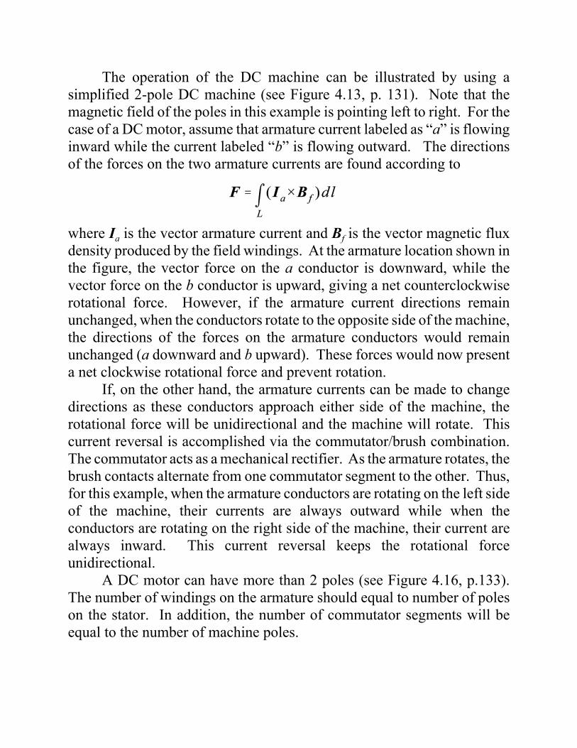
The operation of the DC machine can be illustrated by using asimplified 2-pole DC machine (see Figure 4.13, p. 131). Note that themagnetic field of the poles in this example is pointing left to right. For thecase of a DC motor, assume that armature current labeled as “a” is flowinginward while the current labeled “b” is flowing outward. The directionsof the forces on the two armature currents are found according to
where Ia is the vector armature current and Bf is the vector magnetic fluxdensity produced by the field windings. At the armature location shown inthe figure, the vector force on the a conductor is downward, while thevector force on the b conductor is upward, giving a net counterclockwiserotational force. However, if the armature current directions remainunchanged, when the conductors rotate to the opposite side of the machine,the directions of the forces on the armature conductors would remainunchanged (a downward and b upward). These forces would now presenta net clockwise rotational force and prevent rotation.
If, on the other hand, the armature currents can be made to changedirections as these conductors approach either side of the machine, therotational force will be unidirectional and the machine will rotate. Thiscurrent reversal is accomplished via the commutator/brush combination.The commutator acts as a mechanical rectifier. As the armature rotates, thebrush contacts alternate from one commutator segment to the other. Thus,for this example, when the armature conductors are rotating on the left sideof the machine, their currents are always outward while when theconductors are rotating on the right side of the machine, their current arealways inward. This current reversal keeps the rotational forceunidirectional.
A DC motor can have more than 2 poles (see Figure 4.16, p.133).The number of windings on the armature should equal to number of poleson the stator. In addition, the number of commutator segments will beequal to the number of machine poles.

DC GENERATOR(INDUCED ARMATURE VOLTAGE)
If the operation of the DC machine as a generator is considered, anexpression for the voltage induced at the armature terminals can bedeveloped. As the armature rotates in the magnetic field produced by thefield windings, and emf is induced in the conductors. The induced emf ineach armature turn Vt (shown is defined according to the concept ofmotional induction as
where ua is the vector velocity of the armature conductor, Bf is the vectormagnetic flux density produced by the field windings and Ea is the vectorelectric field associated with the induced emf in the armature conductor.

The magnitude of the velocity of each conductor is given by
where r is the radius of the armature and Tm is the mechanical angularvelocity of the armature in rad/s. The magnitude of the resulting emfelectric field along each conductor is given by
Note that the direction of the emf electric fields are opposite on thearmature turn conductors. The induced emf in each conductor is found byintegrating the emf electric field along the length of the conductor.Assuming the emf electric field is uniform along the conductor, this gives
where l is the length of the armature conductor in the magnetic flux of thefield winding. These induced voltages have opposite polarities so that theyadd to give the overall induced voltage in each armature turn
The magnetic flux density in a DC machine will be non-uniform. If themagnetic flux density is interpreted as an average value, the averagemagnetic flux density can be written as
where Rm is the total magnetic flux per pole and A is the area per pole.Inserting this expression for the average magnetic flux density into theinduced armature turn voltage gives

The overall armature winding voltage (Va) in all of the turns (N) connectedin series is equal to the single turn voltage times the number of turns. Ifthere several of these series combinations of turns connected in parallel,then the overall voltage is divided by the number of parallel paths whichgives
where a is the number of parallel paths. The armature voltage can bewritten as
where the constant Ka is known as the machine or armature constant givenby
The armature constant contains the information about how thearmature winding is configured. The two most common configurations ofDC machine windings are the lap winding and the wave winding.
Lap winding - the number of parallel paths is equal to the numberof machine poles (a = p).
Wave winding - two parallel paths (a = 2).
The lap winding is well-suited for DC machines with high currents and lowvoltages while the wave winding is suitable for DC machines with highvoltages and low currents.

DC MACHINE DEVELOPED TORQUE
The torque developed by a DC machine can be determined bysumming the Lorentz forces on all of the armature conductors. The force(Fc) on an individual armature conductor is given by
where Ic is the conductor current, Bf is the average flux density seen by theconductor as it rotates and the integration is along the length of theconductor located in the magnetic flux (l) produced by the field windings.Assuming a uniform flux density along the length of the conductor, themagnitude of the vector force on the armature conductor is
The current in an individual armature conductor will depend on the numberof parallel paths in the armature (a) and the total armature current (Ia). Theforce on an individual armature conductor in terms of the total armaturecurrent is
The developed torque associated with a single armature conductor (Tc) isgiven by the product of the force on the conductor and the radius of thearmature (r).
The total developed torque (T) is found by multiplying Tc by the totalnumber of conductors in the armature (2N = two conductors per turn × Ntotal turns).

Inserting the previously determined expression for the average flux densityinto the total developed torque equation gives
where Ka is the armature constant. For the case of a DC motor, thearmature output power (Pa) is the product of the developed torque and theangular velocity of the machine (Tm).
For the case of a DC generator, the armature output power is simply theproduct of the armature voltage and the armature current (VaIa). Given thepreviously determined expression for the armature voltage,
the armature output power is
Note that the armature output power is equivalent for a DC motor and a DCgenerator. The armature ouput power is an intermediate power quantity inthe overall operation of a DC motor or generator. If we designate thepower loss components as:
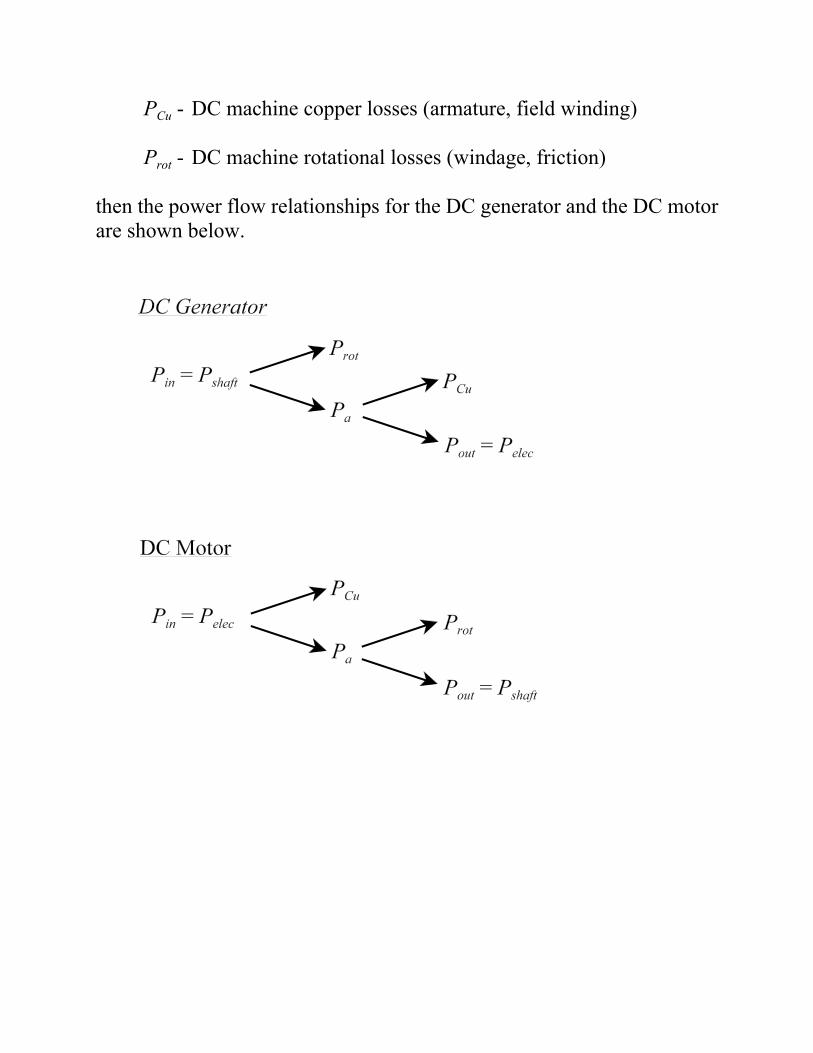
PCu - DC machine copper losses (armature, field winding)
Prot - DC machine rotational losses (windage, friction)
then the power flow relationships for the DC generator and the DC motorare shown below.

Example (DC Machine, armature characteristics)
The armature winding of a four pole DC machine (armature radius r= 12.5cm, armature length l = 25cm) has 33 coils with 7 turns per coil. Thepoles cover 75% of the armature while the average magnetic flux densityper pole is 0.75T. For lap-wound and wave-wound machines, determine(a.) the armature constant (b.) the induced armature voltage when thearmature rotates at 1000rpm (c.) the coil current (d.) the developed torquein the machine when the armature current is 400A (e.) the power developedby the armature.
Lap-Wound machine (a = p = 4)
(a.) N = 33 × 7 = 231 total turns
(b.)
(c.)

(d.)
(e.)
or
Wave-Wound machine (a = 2)
(a.) N = 33 × 7 = 231 total turns
(b.)
(c.)
(d.)
(e.)
or

DC MACHINE MAGNETIZATION CURVES
The equivalent magnetic circuit of the DC machine consists of mmfsources associated with the field windings and the reluctances of thevarious machine components in the direction of the magnetic flux [poles,air gaps, rotor teeth, rotor core and the outer portion of the stator (yoke)](see Figure 4.21, p. 142). At low values of magnetic flux density, thereluctances of the ferromagnetic components in the magnetic circuit arenegligible in comparison to the reluctances of the air gaps. However, athigher values of magnetic flux density, the certain components of themagnetic circuit may saturate (particularly the rotor teeth), and theincreased reluctance of these components begins to affect the overallmagnetic circuit.
The armature voltage is a critical parameter in the determination ofperformance characteristics for the DC machine. The armature voltage hasbeen shown to be proportional to the magnetic flux density per pole and thearmature speed. Thus, the armature voltage will also exhibit nonlinearbehavior when saturation occurs. The analysis of DC machine performancetypically requires that the characteristics of the armature voltage saturationbe known. This information is typically provided in a plot of the armaturevoltage vs. field current (magnetization curve) for a given operating speed.
DC MACHINE CLASSIFICATIONS
One significant advantage of a DC machine is the variety ofperformance characteristics that can be achieved by interconnecting thefield and armature windings in various ways.
The field windings can be excited by a DC source which is connectedonly to the field windings and not connected to the armature. Such aconfiguration is known as a separately excited DC machine. The fieldexcitation can also be provided by permanent magnets. This type ofmachine is also classified as a separately excited machine since thearmature current is independent of the field excitation.
If the field winding current is all or part of the armature current, themachine is known as a self-excited DC machine. There are three differentconfigurations of self-excited DC machines. In a series self-excited DCmachine, the field windings are connected in series with the armature. Ashunt self-excited DC machine results when the field windings areconnected in parallel with the armature. If a combination of series andparallel connections are made between the field and armature windings, thismachine is classified as a compound self-excited DC machine.
If a shunt connection of the field windings is implemented, a variableresistor is typically inserted in series with the field winding in order toeasily control the field winding current. This variable resistor is known asthe field rheostat. The field winding current in shunt-connected windingis typically low (approximately 1 to 2% of the rated armature current).Thus, copper losses in the shunt-connected winding are typically low.
A series connected field winding must carry the much larger armaturecurrent. Thus, the resistance of a series field winding must be kept low inorder that the copper losses of the field winding are not too severe. Aseries field winding will typically have a resistance on the order of tens ofmS’s.

Separately excited DC machine
Self-excited series DC machine
Self-excited shunt DC machine

Self-excited compound DC machine (short shunt)
Self-excited compound DC machine (long shunt)
The various DC machine configurations can be analyzed by includingthe resistances of the field windings, the armature circuit (armature windingresistance and brush resistances) along with the load resistance and the fieldrheostat, if present. The analysis at DC steady-state does not requireinclusion of the various winding inductances. For transient analysis, theseinductances are important.

SEPARATELY EXCITED DC GENERATOR
The complete equivalent circuit of the separately excited DCgenerator is shown below. The individual components of the equivalentcircuit are:
Ra - armature resistance (including the resistance of the armaturewinding along with brush contact resistance)
Rfw - field winding resistanceRfc - field winding resistanceRL - load resistance
Analysis of the resistive network is straightforward assuming the armaturevoltage is known. Note that the terminal voltage is dependent on thearmature voltage and the voltage drop across the armature resistance(dependent on the terminal current). The terminal voltage is given by
The circuit model predicts that the terminal voltage decreases linearly withan increase in the terminal (armature) current. However, due to an effectknown as the armature reaction or the demagnetization effect, the actualterminal voltage is slightly lower than that predicted by the equivalentcircuit. The armature reaction is more pronounced at higher armaturecurrents and is usually neglected at currents below the rated armaturecurrent.

The armature reaction is caused by the fact that the currents inducedin the armature by motional induction create secondary components ofmagnetic field that tend to oppose the magnetic field of the field circuitover a portion of the armature while enhancing the magnetic field of thefield circuit over the remainder of the armature. If the enhanced portion ofthe armature field causes magnetic saturation, the net effect is a reductionin the flux per pole which decreases the armature voltage, and thus,decreases the terminal voltage.
The armature reaction can be modeled as an effective reduction in thefield current. The effective armature current (If,eff) is related to the actualfield current by
where If,AR is the amount by which the field current must be reduced tomodel the armature reaction.
Example (Separately excited DC generator)
A 12 kW, 100V, 1000rpm DC shunt generator has an armatureresistance of Ra = 0.1 S, shunt winding resistance of Rfw = 80 S and Nf =1200 turns per pole. The rated field current is 1 A. The magnetizationcharacteristic at 1000 rpm is given in Figure 4.24 (p. 143). The machineis operated as a separately excited DC generator at 1000 rpm with ratedfield current.
(a.) Determine the terminal voltage at full load neglecting thearmature reaction.
(b.) Determine the terminal voltage at full load accounting for thearmature reaction. Assume the armature reaction at full load isequivalent to 0.06 field Amperes.
( c.) Determine the field current necessary to make the terminalvoltage equal to 100 V at full load.

The machine description provides the following data:
Rated armature power (at full load) = 12 kWRated armature voltage (at full load) = 100 VRated speed = 1000 rpm
The rated armature current is found from the rated power and voltage.
Rated armature current = 12000/100 = 120 A
(a.) The terminal voltage at full-load is given by
(b.) The effective field current accounting for the armature reactionis
At the effective field current, the armature voltage isapproximately 98 V. The resulting terminal voltage is
( c.) If the terminal voltage is 100 V, the corresponding armaturevoltage is
From Figure 4.24, the effective field current is approximately1.4 A. The actual field current is then

SHUNT DC MOTOR
The equivalent circuit of the shunt DC motor is shown below. Notethat for motor operation, a DC voltage source is applied at the inputterminal and the terminal current is assumed to flow into the motor.
The operation of the field circuit is no different from the separately excitedmachine since a constant DC voltage is applied to the field winding (justas the separately excited case). In this regard, the function of the fieldcircuit is independent of the of the armature circuit. However, the input DCsource for the shunt motor must supply a current equal to the sum of thearmature and the field currents.
Example (Shunt DC motor)
The DC machine used in the separately excited DC generator example(12 kW, 100V, 1000 rpm, Ra = 0.1 S, Rfw = 80 S) is used as DC shuntmotor. The motor operates at 1000 rpm with an armature current of 6 A atno-load. Determine
(a.) the resistance value of the field rheostat (Rfc).(b.) the rotational losses of the DC motor at 1000 rpm.

(c.) the speed, developed torque and efficiency given rated armaturecurrent neglecting armature reaction (assume the air gap flux atrated load equals that at no load).
(d.) the speed, developed torque and efficiency given rated armaturecurrent assuming the air gap flux is reduced by 5% from the no-load value due to armature reaction.
(e.) the starting torque if the starting armature current is limited to150% of its rated value (neglect armature reaction).
(f.) the starting torque if the starting armature current is limited to150% of its rated value accounting for armature reaction withIf,AR = 0.16 A.
(a.) The armature voltage at no-load (Ia = 6 A) is given by
From the magnetization curve for the machine, an armaturevoltage of 99.4 V at 1000 rpm requires a field current ofapproximately 0.99 A. Thus,
(b.) At no-load, all of the armature power is dissipated in the formof rotational loss.

(c.) The motor is loaded (full load) such that the armature carriesthe rated current of Ia = 120 A. The corresponding full loadarmature voltage is
According to the armature voltage definition,
the ratio of the full-load armature voltage to the no-loadarmature voltage is
assuming that the full-load magnetic flux is equal to that of theno-load case. The full load angular velocity is then
The resulting full-load torque is
The motor output power is equal to the armature power minusthe rotational losses.

The motor input power is equal to the product of the terminalvoltage and current.
The motor efficiency is defined by the ratio of output power toinput power.
(d.) If the air gap flux is reduced by 5% from no-load to full-load,the ratio of full-load to no-load armature voltages gives
The full load angular velocity is then
The resulting full-load torque is
The calculations for the output power, the input power, and themotor efficiency are identical to those in part (c.). The actualmotor efficiency decrease from that of part (c.) since the motorrotational losses would be larger at a higher speed.

(e.) The starting torque can be found according to
The product of KaRm can be found from the armature emfequation evaluated at no-load or full-load.
The starting torque is given by
(f.) The effective field current is
From the magnetization curve, the armature voltage for thisfield current is 93.5 V at a speed of 1000 rpm. The fluxcondition for this case is
which gives the following starting torque.
SERIES DC MOTOR
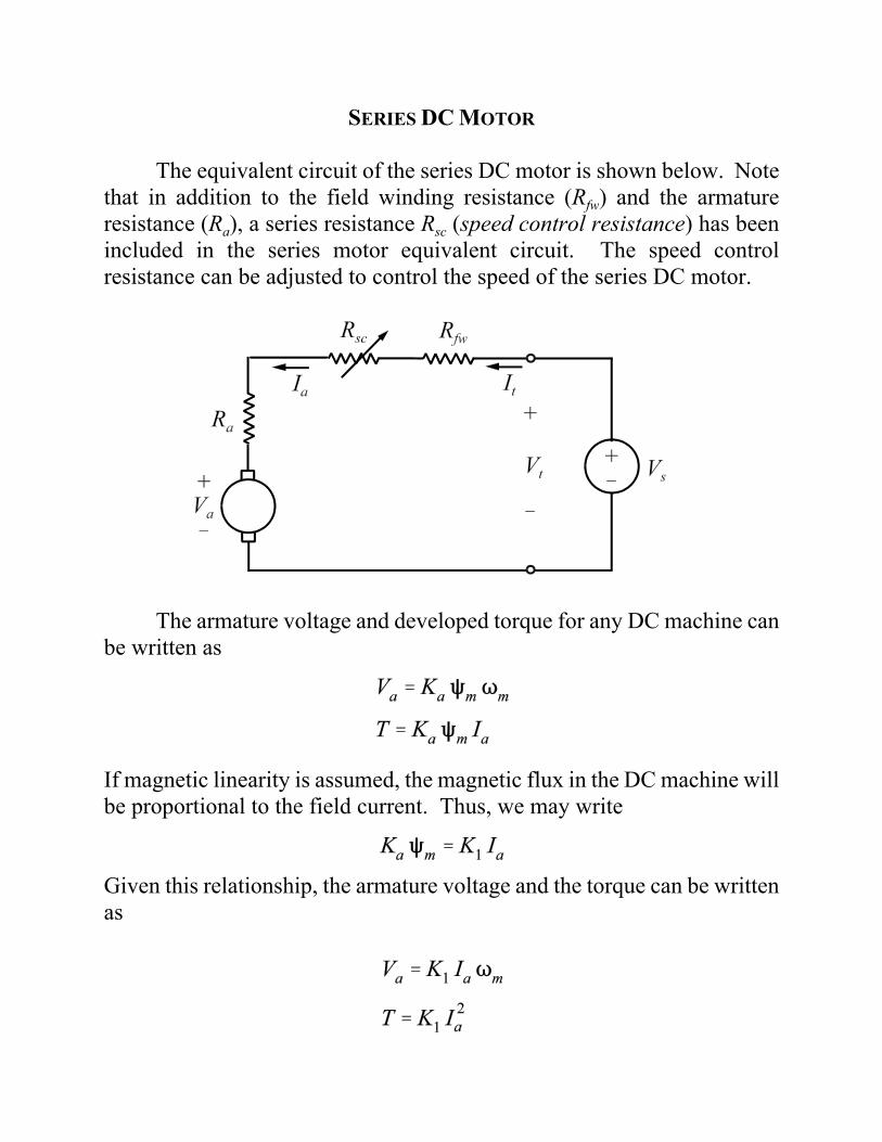
The equivalent circuit of the series DC motor is shown below. Notethat in addition to the field winding resistance (Rfw) and the armatureresistance (Ra), a series resistance Rsc (speed control resistance) has beenincluded in the series motor equivalent circuit. The speed controlresistance can be adjusted to control the speed of the series DC motor.
The armature voltage and developed torque for any DC machine canbe written as
If magnetic linearity is assumed, the magnetic flux in the DC machine willbe proportional to the field current. Thus, we may write
Given this relationship, the armature voltage and the torque can be writtenas

The armature voltage is the series DC motor is
Combining the equations for the armature voltage gives
This equation can be rewritten in terms of torque by substituting thefollowing relationship:
which yields
As shown in the previous equation, the series DC motor is characterized byhigh torque at low speeds and low torque at high speeds.

Example (Series DC motor)
A fan is driven by a 220 V, 7 hp series DC motor which draws 25 Aand runs at 300 rpm when connected to a 220 V supply with Rsc = 0. Thearmature resistance of the DC motor is Ra = 0.6 S and the resistance of thefield winding is Rfw = 0.4 S. The torque required by the fan is proportionalto the square of the motor speed. Neglect the rotational losses and armaturereaction. Determine
(a.) the power delivered to the fan and the torque developed by themotor.
(b.) the value of Rsc necessary to reduce the motor speed to 200 rpmand the power delivered to the fan at this speed.
(a.) The armature voltage of the series DC motor is given by
The armature power is equal to the output power whenrotational losses are neglected. Thus, the power delivered to thefan is
The developed torque is equal to the armature power divided bythe motor mechanical speed.

(b.) The constant K1 can be determined from the torque found inpart (a.) at Tm = 300 rpm.
If the required torque is proportional to the square of the speed,then
The power delivered to the fan at 200 rpm is
The value of speed control resistance required is found from
The resulting speed control resistance is