dc electric scissorsskykorea.co/data_pdf/service/165983.pdf · 2016. 10. 25. · ansi/sia...
TRANSCRIPT

.
DC ELECTRIC SCISSORS MODELS SJIII 3215 SJIII 3219
SERVICE MANUAL (KC)
165983AA November 2013

Skyjack Service Center 3451 Swenson Ave. St. Charles, Illinois, 60174 USAPhone: 630-262-0005Toll Free: 1-800-275-9522Fax: 630-262-0006Email: [email protected]
Parts (North America)Toll Free: 1-800-965-4626Toll Free Fax: 1-888-782-4825Email: [email protected]
Parts & Service (Europe) Unit 1 Maes Y Clawdd, Maesbury Road Industrial Estate Oswestry, Shropshire SY10 8NN UKPhone: +44-1691-676-235Fax: +44-1691-676-238Email: [email protected]
Skyjack BrasilAlameda Júpiter, 710 American Park EmpresarialIndaiatuba, SP, Brasil 13347-653Tel.: +55 19 3936 0132
Skyjack Australia Pty Ltd.4 Coates Place, Wetherill ParkNew South Wales 2164AustraliaPhone: +61 (0) 28786 3200Fax: +61(0) 28786 3222
This manual is based on Serial Numbers:
SJIII 3215 10 000 996 & AboveSJIII 3219 22 057 772 & Above
Please refer to the website www.skyjack.com for older Serial Numbers.

SJIII DC ElectricSJIII 3215 SJIII 3219165983
SKYJACK, Page 3
SERVICE AND MAINTENANCE
Table of Contents
Section 1 - Scheduled Maintenance InspectionsTable of Contents
Section 2 - Maintenance Tables Table of Contents
Section 3 - SchematicsTable of Contents
Section 4 - TroubleshootingTable of Contents
Section 5 - ProceduresTable of Contents

SKYJACK, Page 4 SJIII DC ElectricSJIII 3215 SJIII 3219
165983
Section 1 - Scheduled MaintenanceOperator’s Responsibility for Maintenance
The Safety Alert Symbol identifies important safety messages on aerial platforms, safety signs in manuals or elsewhere. When you see this symbol, be alert to the possibility of personal injury or death. Follow the instructions in the safety message.
This Safety Alert Symbol means attention!
Become alert! Your safety is involved.
DANGER
DANGER indicates an imminently hazardous situation which, if not avoided, will result in death or serious injury.
WARNING
WARNING indicates a potentially hazardous situation which, if not avoided, could result in death or serious injury.
CAUTION
CAUTION indicates a potentially hazardous situation which, if not avoided, may result in minor or moderate injury. It may also be used to alert against
unsafe practices.
IMPORTANT
IMPORTANT indicates a procedure) essential for safe operation and which, if not followed, may result in a malfunction or damage to the aerial platform.

SJIII DC ElectricSJIII 3215 SJIII 3219165983
SKYJACK, Page 5
Operator’s Responsibility for MaintenancePurpose of Equipment .................................................................................................................................................7Use of Equipment ........................................................................................................................................................7Manuals ........................................................................................................................................................................7Operator .......................................................................................................................................................................7Service Policy and Warranty ........................................................................................................................................7Optional Accessories ...................................................................................................................................................7Scope of this Manual ...................................................................................................................................................8Operator Safety Reminders .........................................................................................................................................8Electrocution Hazard ...................................................................................................................................................9Safety Precautions .....................................................................................................................................................10Maintenance and Inspection Schedule .....................................................................................................................13Owner’s Annual Inspection Record ...........................................................................................................................13Replacement Parts .....................................................................................................................................................13Maintenance and Service Safety Tips .......................................................................................................................13Hydraulic System & Component Maintenance and Repair ......................................................................................14Maintenance Hints .....................................................................................................................................................14
Service and MaintenanceAbout this Section ......................................................................................................................................................15Service Bulletins .........................................................................................................................................................15Maintenance and Inspection .....................................................................................................................................15Maintenance Instructions ...........................................................................................................................................15
Tables1.1 Owner’s Annual Inspection Record ................................................................................................................161.2 Maintenance and Inspection Checklist ...........................................................................................................17
Scheduled Maintenance1.1 Scheduled Maintenance Inspections ..............................................................................................................181.2 Function Tests..................................................................................................................................................25
1 Section 1SCHEDULE MAINTENANCE INSPECTIONS
Table of Contents

SKYJACK, Page 6 SJIII DC ElectricSJIII 3215 SJIII 3219
165983
Notes

SJIII DC ElectricSJIII 3215 SJIII 3219165983
SKYJACK, Page 7
Section 1 - Scheduled Maintenance Operator’s Responsibility for Maintenance
SKYJACK is continuously improving and expanding product features on its equipment, therefore, specifications and dimensions are subject to change without notice.
Aerial Platform and Mobile Elevating Work Platform DefinitionA mobile device that has a positionable platform supported from ground level by a structure.
Purpose of EquipmentThe SKYJACK SJIII DC Electric series aerial platforms are designed to transport and raise personnel, tools and materials to overhead work areas.
Use of EquipmentThe aerial platform is a highly maneuverable, mobile work station. Work platform elevation and elevated driving must only be done on a firm level surface.
ManualsOperating The operating manual is considered a fundamental part of the aerial platform. It is a very important way to
communicate necessary safety information to users and operators. A complete and legible copy of this manual must be kept in the provided weather-resistant storage compartment on the aerial platform at all times.
Service & Maintenance The purpose of this is to provide the customer with the servicing and maintenance procedures essential for
the promotion of proper machine operation for its intended purpose.
All information in this manual should be read and understood before any attempt is made to service the machine. The updated copy of the manuals are found on the company’s website: www.skyjack.com.
OperatorThe operator must read and completely understand both this operating manual and the safety panel label located on the platform and all other warnings in this manual and on the aerial platform. Compare the labels on the aerial platform with the labels found within this manual. If any labels are damaged or missing, replace them immediately.
Service Policy and WarrantySKYJACK warrants each new SJIII Series work platform to be free of defective parts and workmanship for the first 24 months. Any defective part will be replaced or repaired by your local SKYJACK dealer at no charge for parts or labor. Contact the SKYJACK Service Department for warranty statement extensions or exclusions.
Optional AccessoriesThe SKYJACK aerial platform is designed to accept a variety of optional accessories. These are listed under the “Standard and Optional Features” Table of the operating manual. Operating instructions for these options (if equipped) are located in the “Operation” Section of the operating manual.
For options not listed under “Standard and Optional Features,” contact the SKYJACK Service Department at
( : 44-1691-676-2357 : 44-1691-676-239
Include the model and serial number for each applicable aerial platform.

SKYJACK, Page 8 SJIII DC ElectricSJIII 3215 SJIII 3219
165983
Section 1 - Scheduled MaintenanceOperator’s Responsibility for Maintenance
Scope of this Manuala. This manual applies to the KC version of the SJIII Series aerial platform models listed on Table 2.1.
- Equipment identified with “KC” meets the requirements for South Korea, i.e., Act 2008-75 and the corresponding KS B ISO 16368:2004 Korean standard.
a. Operators are required to conform to national, state or territorial/provincial and local health and safety regulations applicable to the operation of this aerial platform.
WARNING
Failure to comply with your required responsibilities in the use and operation of the aerial platform could result in death or serious injury!
Operator Safety RemindersA study conducted by St. Paul Travelers showed that most accidents are caused by the failure of the operator to follow simple and fundamental safety rules and precautions.
You, as a careful operator, are the best insurance against an accident. Therefore, proper usage of this aerial platform is mandatory. The following pages of this manual should be read and understood completely before operating the aerial platform.
Common sense dictates the use of protective clothing when working on or near machinery. Use appropriate safety devices to protect your eyes, ears, hands, feet and body.
Any modifications from the original design are strictly forbidden without written permission from SKYJACK Inc.
WARNING
Risk of an electric shock - Do not remove an Anti-Static Strip from the aerial platform.
Anti-StaticStrip

SJIII DC ElectricSJIII 3215 SJIII 3219165983
SKYJACK, Page 9
Section 1 - Scheduled Maintenance Operator’s Responsibility for Maintenance
Electrocution HazardThis aerial platform is not electrically insulated. Maintain a Minimum Safe Approach Distance (MSAD) from energized power lines and parts as listed below. The operator must allow for the platform to sway, rock or sag. This aerial platform does not provide protection from contact with or proximity to an electrically charged conductor.
Per ANSI A92.6-2006 8.10(7)“The operator shall perform only that work for which he or she is qualified, in compliance with all applicable safety related work practices intended to prevent electric shock covered by the Code of Federal Regulations (CFR) 1910.333. The operator’s level of competence shall be established only by persons qualified to do so. Op-erators shall maintain the appropriate minimum approach distance (MAD) from energized power lines and parts covered by CFR 1910.333 (c).”
Unqualified persons must maintain a minimum approach distance of 10 feet from any energized power line up to 50 kV. Energized power lines over 50 kV require a greater minimum approach distance to be maintained. Refer to CFR 1910.333.
As per CSA B354.2-01“The operator shall maintain the minimum safe approach distance (MSAD) from energized conductors at all times in accordance with the authority having jurisdiction.”
DO NOT USE THE AERIAL PLATFORM AS A GROUND FOR WELDING.DO NOT OPERATE THE AERIAL PLATFORM DURING LIGHTNING OR STORMS.
DO NOT OPERATE THE AERIAL PLATFORM NEAR POWER LINES. MAINTAIN A MINIMUM SAFE AP-PROACH DISTANCE (MSAD) FROM ENERGIZED POWER LINES.
Voltage Range Minimum Safe Approach Distance(Phase to Phase) (Feet)
0 to 300V Avoid Contact
Over 300V to 50KV 10
Over 50KV to 200KV 15
Over 200KV to 350KV 20
Over 350KV to 500KV 25
Over 500KV to 750KV 35
Over 750KV to 1000KV 45
60023AD-ANSI
DANGER
FAILURE TO AVOID THIS HAZARD WILL RESULT IN DEATH OR SERIOUS INJURY!
Avoid Power Lines
Minimum Safe Approach DistanceANSI/SIA A92.6-2006 & CSA B354.2-01 Requirements

SKYJACK, Page 10 SJIII DC ElectricSJIII 3215 SJIII 3219
165983
Section 1 - Scheduled MaintenanceOperator’s Responsibility for Maintenance
Safety PrecautionsKnow and understand the safety precautions before going on to next section.
WARNING
Failure to heed the following safety precautions could result in tip over, falling, crushing, or other hazards leading
to death or serious injury.
• KNOW all national, state or territorial/provincial and local rules which apply to your aerial platform and jobsite.
• TURN main power disconnect switch “ ” off when leaving the aerial platform unattended. Remove the key to prevent unauthorized use of the aerial platform.
• WEAR all the protective clothing and personal safety devices issued to you or called for by job conditions.
• DO NOT wear loose clothing, dangling neckties, scarves, rings, wristwatches or other jewelry while operating this lift.
• AVOID entanglement with ropes, cords or hoses.
• AVOID falling. Stay within the boundaries of the guardrails.
• DO NOT raise the aerial platform in windy or gusty conditions.
• DO NOT increase the lateral surface area of the platform. Avoid tenting.
• DO NOT drive elevated on a soft or uneven surface.
• DO NOT elevate the aerial platform if it is not on a firm, level surface.
• DO NOT drive elevated near depressions or holes of any type, loading docks, debris, drop-offs or surfaces that may affect the stability of the aerial platform.
• IF OPERATION IN AREAS WITH HOLES OR DROP-OFFS IS ABSOLUTELY NECESSARY, elevated driving shall not be allowed. Position the aerial platform horizontally only with the platform fully-lowered. After ensuring that all 4 wheels or outriggers (if equipped) have contact with a firm, level surface, the aerial platform can be elevated. After elevation, the drive function must not be activated.
• DO NOT elevate or drive elevated on a slope. Elevated driving must be done on a firm, level surface.
• DO NOT ascend or descend a grade when elevated. When fully-lowered, ascend or descend grades up to maximum rated inclines listed in Table 4-3a and Table 4-3b.

SJIII DC ElectricSJIII 3215 SJIII 3219165983
SKYJACK, Page 11
Section 1 - Scheduled Maintenance Operator’s Responsibility for Maintenance
Safety Precautions (Continued)Know and understand the safety precautions before going on to next section.
• DO NOT operate on surfaces not capable of holding the weight of the aerial platform including the rated load, e.g. covers, drains, and trenches.
• DO NOT operate an aerial platform that has ladders, scaffolding or other devices mounted on it to increase its size or work height. It is prohibited.
• DO NOT exert side forces on aerial platform while elevated.
• DO NOT use the aerial platform as a crane. It is prohibited.
• DO NOT sit, stand or climb on the guardrails. It is prohibited.
• DO NOT climb on scissor arm assembly. It is prohibited.
• AVOID overhead obstructions. Be aware of overhead obstructions or other possible hazards around aerial platform when lifting or driving.
• AVOID crushing hazards. Be aware of crushing hazards when lifting or driving. Keep all body parts inside the aerial platform.
• DO NOT raise the aerial platform while the aerial platform is on a truck, fork lift or other device or vehicle.
• DO NOT lower the platform unless the area below is clear of personnel and obstructions.
• ENSURE that there are no personnel or obstructions in the path of travel, including blind spots.
• BE AWARE of blind spots when operating the aerial platform.
• DO NOT use with improperly inflated/damaged tires or wheels. Refer to Section 2: Wheel/Tire Assembly.
• ENSURE ALL tires are in good condition and lug nuts are properly tightened.
• DO NOT alter or disable limit switches or other safety devices.

SKYJACK, Page 12 SJIII DC ElectricSJIII 3215 SJIII 3219
165983
Section 1 - Scheduled MaintenanceOperator’s Responsibility for Maintenance
Safety Precautions (Continued)Know and understand the safety precautions before going on to next section.
• DO NOT use the aerial platform without guardrails, locking pins and the entry gate(s) in place.
• DO NOT use under influence of alcohol or drugs.
• STUNT driving and horseplay are prohibited.
• DO NOT exceed the rated capacity of the aerial platform.
• DO NOT distribute load unevenly.
• DO NOT operate if aerial plat-form is not working properly or if any parts are damaged or worn.
• DO NOT leave aerial platform unattended with key in key switch.
• DO NOT position the aerial platform against another object to steady the platform.
• DO NOT place materials on the guardrails or materials that exceed the confines of the guardrails unless approved by Skyjack.
WARNING
Entering and exiting the aerial platform should only be done using the three points of contact.
•Use only equipped access openings.• Enter and exit only when the aerial
platform is in the fully retracted position.
• Do use three points of contact to enter and exit the platform. Enter and exit the platform from the ground only. Face the aerial platform when entering or exiting the platform.
• Three points of contact means that two hands and one foot or one hand and two feet are in contact with the aerial platform or the ground at all times during entering and exiting.
WARNING
An operator should not use any aerial platform that:
• does not appear to be working properly.• has been damaged or appears to have worn or
missing parts.• has alterations or modifications not approved
by the manufacturer.• has safety devices which have been altered or
disabled.• has been tagged or locked out for non-use or
repair.
Failure to avoid these hazards could result in death or serious injury.
Jobsite Inspection• Do not use in hazardous locations.• Perform a thorough jobsite inspection prior to
operating the aerial platform, to identify potential hazards in your work area.
• Be aware of moving equipment in the area. Take appropriate actions to avoid collision.
SJIII DC ElectricSJIII 3215 SJIII 3219165983
SKYJACK, Page 13
Section 1 - Scheduled Maintenance Operator’s Responsibility for Maintenance
Maintenance and Inspection ScheduleThe actual operating environment of the work platform governs the use of the maintenance schedule. The inspection points covered in Table 1.2. Maintenance and lnspection Checklist, indicates the areas of the aerial platform to be maintained or inspected and at what intervals the maintenance and inspections are to be performed.
Owner’s Annual Inspection RecordIt is the responsibility of the owner to arrange quarterly and annual inspections of the aerial platform. Table 1.1. Owner’s Annual lnspection Record is to be used for recording the date of the inspection, owner’s name, and the person responsible for the inspection of the work platform.
Replacement PartsUse only original replacement parts. Parts such as batteries, wheels, railings, etc. with weight and dimensions different from original parts will affect stability of the aerial platform and must not be used without manufacturer’s consent.
All replacement tires must be of the same size and load rating as originally supplied tires; to maintain safety and stability of aerial platform.
Consult SKYJACK’s Service Department for optional tires specifications and installation.
WARNING
Any unit that is damaged or not operating properly must be immediately tagged and removed from service until proper repairs
are completed.
Maintenance and Service Safety TipsMaintenance and repair should only be performed by personnel who are trained and qualified to service this aerial platform.
All maintenance and service procedures should be performed in a well lighted and well ventilated area.
Anyone operating or servicing this aerial platform must read and completely understand all operating instructions and safety hazards in this manual and operating manual.
All tools, supports and lifting equipment to be used must be of proper rated load and in good working order before any service work begins. Work area should be kept clean and free of debris to avoid contaminating components while servicing.
All service personnel must be familiar with employer and governmental regulations that apply to servicing this type of equipment.
Keep sparks and flames away from all flammable or combustible materials.
Properly dispose of all waste material such as lubricants, rags, and old parts according to the relative law provisions obtaining in the country.
Before attempting any repair work, turn Battery Disconnect Switch to the “OFF” position.
Preventive maintenance is the easiest and least expensive type of maintenance.

SKYJACK, Page 14 SJIII DC ElectricSJIII 3215 SJIII 3219
165983
Section 1 - Scheduled MaintenanceOperator’s Responsibility for Maintenance
Hydraulic System & Component Maintenance and RepairThe following points should be kept in mind when working on the hydraulic system or any component:
1. Any structure has limits of strength and durability. To prevent failure of structural parts of hydraulic components, relief valves which limit pressure to safe operating values are included in the hydraulic circuits.
2. Tolerance of working parts in the hydraulic system is very close. Even small amounts of dirt or foreign materials in the system can cause wear or damage to components, as well as general faulty operation of the hydraulic system. Every precaution must be taken to assure absolute cleanliness of the hydraulic oil.
3. Whenever there is a hydraulic system failure which gives reason to believe that there are metal particles or foreign materials in the system, drain and flush the entire system and replace the filter cartridges. A complete change of oil must be made under these circumstances.
4. Whenever the hydraulic system is drained, check the magnets in the hydraulic reservoir for metal particles. If metal particles are present, flush the entire system and add a new change of oil. The presence of metal particles also may indicate the possibility of imminent component failure. A very small amount of fine particles is normal.
5. All containers and funnels used in handling hydraulic oil must be absolutely clean. Use a funnel when necessary for filling the hydraulic oil reservoir, and fill the reservoir only through the filter opening. The use of cloth to strain the oil should be avoided to prevent lint from getting into the system.
6. When removing any hydraulic component, be sure to cap and tag all hydraulic lines involved. Also, plug the ports of the removed components.
NOTESamples of hydraulic oil should be drawn from the reservoir and tested annually. These samples should be taken when the oil is warmed through normal operation of the system. The sample should be analyzed by a qualified lubrication specialist to determine if it is suitable for continued use.
Oil change intervals will depend on the care used in keeping the oil clean, and the operating conditions. Dirt and/or moisture cotamination will dictate that the oil should be changed more often. Under normal use and operating conditions, the hydraulic oil should be changed every two years. Refer
to Table 1.2 of this manual.
7. All hydraulic components must be dis-assembled in spotlessly clean surroundings. During disassembly, pay particular attention to the identification of parts to assure proper reassembly. Clean all metal parts in a clean mineral oil solvent. Be sure to thoroughly clean all internal passages. After the parts have been dried thoroughly, lay them on a clean, lint-free surface for inspection.
8. Replace all O-rings and seals when overhauling any component. Lubricate all parts with clean hydraulic oil before reassembly. Use small amounts of petroleum jelly to hold O-rings in place during assembly.
9. Be sure to replace any lost hydraulic oil when completing the installation of the repaired component, and bleed any air from the system when required.
10. All hydraulic connections must be kept tight. A loose connection in a pressure line will permit the oil to leak out or air to be drawn into the system. Air in the system can cause damage to the components and noisy or erratic system operation.
Maintenance HintsThree simple maintenance procedures have the greatest effect on the hydraulic system performance, efficiency and life. Yet, the very simplicity of them may be the reason they are so often overlooked. What are they? Simply these:
1. Change filters annually. The filters will need to be changed more often depending on the operating conditions. Dirty, dusty, high moisture environments may cause the hydraulic system to be contaminated more quickly.
2. Maintain a sufficient quantity of clean hydraulic oil of the proper type and viscosity in the hydraulic reservoir.
3. Keep all connections tight.

SJIII DC ElectricSJIII 3215 SJIII 3219165983
SKYJACK, Page 15
Section 1 - Scheduled Maintenance Service and Maintenance
About this SectionThis section contains the maintenance and inspection schedule that is to be performed.
References are made to the procedures in Section 5 that outline detailed step-by-step instructions for checks and replacements.
Service BulletinsBefore performing any scheduled maintenance inspection procedure, refer to service bulletins found in our web site: www.skyjackinc.com for updates related to service and maintenance of this aerial platform.
Maintenance and InspectionDeath or injury can result if the aerial platform is not kept in good working order. Inspection and maintenance should be performed by competent personnel who are trained and qualified on mantenance of this aerial platform.
WARNING
Failure to perform each procedure as pre-sented and scheduled may cause death,
serious injury or substantial damage.
NOTEPreventive maintenance is the easiest and
least expensive type of maintenance.
• Unless otherwise specified, perform eachmaintenance procedure with the aerial platform in the following configuration:
- Aerial platform parked on a flat and level surface - Disconnect the battery by turning the main power disconnect switch to the “OFF” position.
• Repairanydamagedormalfunctioncomponentsbefore operating aerial platform.
• Keeprecordsonallinspections.
Maintenance InstructionsThis manual consists of four schedules to be done for maintaining on an aerial platform. Inspection schedule frequency is shown below:
Inspection ScheduleDaily AFrequently A + BAnnually A + B + CBi-annually A + B + C + D
• Make copies of the maintenance and inspection checklist to be used for each inspection.
• Checkthescheduleonthechecklistforthetypeofinspection to be performed.
• Placeacheck in theappropriateboxaftereachinspection procedure is completed.
• Usethemaintenanceandinspectionchecklistandstep-by-step procedures in Section 5 to perform these inspections.
• Ifanyinspectionreceivesafail,tagandremovetheaerial platform from service.
• If any aerial platform component(s) has been repaired, an inspection must be performed again before removing the tag. Place a check in the repair column.
LegendP = PassF = FailR = Repaired

SKYJACK, Page 16 SJIII DC ElectricSJIII 3215 SJIII 3219
165983
Section 1 - Scheduled MaintenanceService and Maintenance
Table 1.1 Owner’s Annual Inspection Record
1000AA
**
20__20__ 20__20__ 20__ 20__*
Model Number: _________________ Serial Number:__________________
This decal is located on the scissor assembly. It must be completed after an annual inspection has been completed. Do not use the aerial platform if an inspection has not been recorded in the last 13 months.
20__20__ 20__
Pictorial Description
*
Inspection Date
**
Inspector Signature

SJIII DC ElectricSJIII 3215 SJIII 3219165983
SKYJACK, Page 17
Section 1 - Scheduled Maintenance Service and Maintenance
Table 1.2 Maintenance and Inspection Checklist
Serial Number:
Model:
Hourmeter Reading: Name (Printed):
Date:
Time: Signature:
INSPECTION FREQUENCYDAILY
P - PASS FREQUENTLYF - FAIL ANNUALLYR - REPAIRED BI-ANNUALLY
P F R P F R
Maintenance Support
1002AC
A - Perform Visual and Daily Maintenance Inspections & Functions Test. Refer to Section 2 of the Operating Manual.B - Perform Scheduled Maintenance Inspection every three months or 150 hrs. Refer to Section 1 of this manual.C - Perform Scheduled Maintenance Inspection every year. Refer to Section 1 of this manual.D - Perform Scheduled Maintenance Inspection every 2 years. Refer to Section 1 of this manual.* Perform scheduled inspection every three months or 150 hours.† - Refer to Skyjack's website @ www.skyjack.com for latest service bulletins porior to performing quarterly or yearly inspection.
Note: Make a copy of this page or visit the Skyjack web site:www.skyjack.com for a printable copy.
A, B
Test Horn A, B
Test Pothole Sensor A, B
Test Elevated Drive Speed A, B
Main Manifold A, B Test Brakes A, B
Emergency Lowering Access Rod(If Equipped)
A, BTest Platform Raising/Lowering
Hydraulic Pump and Motor A, B Test Steering A, B
Electrical Panel A, B Test Driving A, B
Hydraulic Tank A, B, C Test Platform Emergency Stop A, B
Hydraulic Oil A, B, C Test Enable Trigger Switch A, B
Hydraulic/Electric Tray Side Test Free-wheeling A, B
Pothole Protection Device A, B Platform Control Console
Tie Rod (Conventionals) A, B Test Lower/Neutral/Raise Switch A, B
Greasing Points A, B, C Test Emergency Lowering A, B
Steer Cylinder Assembly A, B Test Base Emergency Stop A, B
Wheel/Tire Assembly A, B Test Off/Platform/Base A, B
Battery Charger A, B Test Main Power Discconect Switch A, B
Battery A, B Base Control Console
Pothole Protection Device A, B Lift Cylinder(s) A, B
Battery Tray A, B Function Tests
Ladder A, B Scissor Bumpers A, B
Battery Tray Side Rollers A, B
Brakes A, B, C A, B
AC Outlet Receptacle A, B Scissor Assembly A, B
Free-wheeling Valve Knob(Compacts - Front Side)
A, BLift Mechanism
Main Power Disconnect Switch A, B Manuals A, B
Base Control Switches A, B Powered Extension Control Console(If Equipped)
A, B
Limit Switches A, B AC Outlet on Platform A, B
Entrance Side Platform Control Console A, B
Schedule ScheduleSchedule Maintenance Inspections Platform Assembly
Labels A Lanyard Attachment Anchors A, B
Frequently*† A + B
Annually† A + B + C
Bi-annually† A + B + C + D
Table 1.2 MAINTENANCE AND INSPECTION CHECKLIST
Each item shall be inspected using the the appropriate section of the Skyjack operating manual.As each item is inspected, write the apropriate grade in the box.
Inspection Schedule
Daily A
q q
q q

SKYJACK, Page 18 SJIII DC ElectricSJIII 3215 SJIII 3219
165983
Section 1 - Scheduled MaintenanceService and Maintenance
1.1 Scheduled Maintenance InspectionsBegin the scheduled maintenance inspections by checking each item in sequence for the conditions listed in this section.
WARNING
To avoid injury, do not operate an aerial platform until all malfunctions have been
corrected.
WARNING
To avoid possible injury, ensure aerial platform power is off during your visual
and daily maintenance inspections.
ElectricalMaintaining the electrical components is essential to good performance and service life of the aerial platform.
Inspect the following areas for chafed, corroded and loose wires:
• basetoplatformcablesandwiringharness• batterytraywiringharnesses• hydraulic/electricalwiringharnesses
HydraulicMaintaining the hydraulic components is essential to good performance and service life of the aerial platform.
Perform a visual inspection around the following areas:• hoses and fittings• all hydraulic cylinders• all hydraulic manifolds• the underside of the base• ground area under the aerial platform
1.1-1 LabelsRefer to the labels section in this manual and determine that all labels are in place and are legible.
1.1-2 Limit SwitchesDetecting limit switch malfunction is essential to safe aerial platform operation. Ensure limit switches are properly secured and movement is not obstructed.
Visually inspect all limit switch located inside the scissor arms and the outrigger assemblies for the following:
• brokenormissingactuatorarm• missingfasteners• loosewiring
Pothole Protection Limit Switch
High Speed Limit Switch

SJIII DC ElectricSJIII 3215 SJIII 3219165983
SKYJACK, Page 19
Section 1 - Scheduled Maintenance Service and Maintenance
1.1-3 Entrance Side
• Main Power Disconnect Switch - Turn main power disconnect switch to
“ ” off position.
- Ensure all cables are secure and switch is in proper working condition.
• Base Control Switches - Ensure there are no signs of visible
damage and all switches are in their neutral positions.
• Free-wheeling Valve Knob(SJIII 3215/3219 - Front Side)
- Ensure there are no loose or missing parts and there is no visible damage.
• Brakes - Ensure there are no loose or missing
parts and there is no visible damage.
- Ensure tabs are not locked.
• 220V Outlet Receptacle - Ensure receptacle is free from dirt and
obstructions.
• Ladder - Ensure there are no loose or missing
parts and there is no visible damage.
Main PowerDisconnect Switch
Base Control Console
220V Outlet Receptacle
Ladder
Brakes
Free-wheeling Valve

SKYJACK, Page 20 SJIII DC ElectricSJIII 3215 SJIII 3219
165983
Section 1 - Scheduled MaintenanceService and Maintenance
1.1-4 Battery Tray Side
• Pothole Protection Device - Ensure mechanisms have no sign of
visible damage and are free from dirt and obstructions.
• Battery Tray - Ensure tray latch is secure and in proper
working order.
• Battery Charger (Compacts - Entrance Side)
- Ensure charger is secure and shows no visible damage.
• Battery Proper battery condition is essential to
good performance and operational safety. Improper fluid levels or damaged cables and connections can result in component damage and hazardous conditions.
WARNING
Explosion hazard. Keep flames and sparks away. Do not smoke
near batteries.
WARNING
Battery acid is extremely corrosive - Wear proper eye and facial protec-tion as well as appropriate protective clothing. If contact occurs, immedi-ately flush with cold water and seek
medical attention.
1. Check battery case for damage.
2. Clean battery terminals and cable ends thoroughly with a terminal cleaning tool or wire brush.
3. Ensure all battery connections are tight.
4. If applicable, check battery fluid level. If plates are not covered by at least 13 mm (1/2”) of solution, add distilled or demineralized water.
5. Replace battery if damaged or incapable of holding a lasting charge.
WARNING
Use original or manufacturer-approved parts and components for the aerial
platform.
Pothole Protection Device
Battery Tray
Battery
Hydraulic/Electric Tray
Battery Charger

SJIII DC ElectricSJIII 3215 SJIII 3219165983
SKYJACK, Page 21
Section 1 - Scheduled Maintenance Service and Maintenance
• Steer Cylinder Assembly - Ensure steer cylinder assembly is
properly secured and there are no loose or missing parts.
• Wheel/Tire Assembly The aerial platform is either equipped with
solid rubber tires or foam-filled tires. Tire and/or wheel failure could result in an aerial platform tip-over. Component damage may also result if problems are not discovered and repaired in a timely fashion.
- Check all tire treads and sidewalls for cuts, cracks, punctures and unusual wear.
- Check each wheel for damage and cracked welds.
- Check each lug nut for proper torque to ensure none are loose.
- Check wheel motor assembly for loose or missing parts and signs of visible damage.
- Ensure wheels are aligned and true vertically and horizontally.
• Greasing Points - Ensure greasing points have no sign of
visible damage and are free from dirt and obstructions.
B - Frequent Inspection - Locate grease fittings and pump grease
as needed.
Steer Cylinder
Tie RodWheel Motor
Greasing Point
Conventional
Wheel/Tire
Wheel/Tire

SKYJACK, Page 22 SJIII DC ElectricSJIII 3215 SJIII 3219
165983
Section 1 - Scheduled MaintenanceService and Maintenance
1.1-5 Hydraulic/Electric Tray Side - Ensure tray latch is secure and in proper
working order.
• Pothole Protection Device - Ensure mechanisms have no sign of
visible damage and are free from dirt and obstructions.
• Hydraulic Tank - Ensure hydraulic filler cap is secure.
- Ensure tank shows no visible damage and no evidence of hydraulic leakage.
• Hydraulic Oil - Ensure platform is fully lowered, and then
visually inspect the sight gauge located on the side of the hydraulic oil tank.
- The hydraulic oil level should be at or slightly above the top mark of the sight glass.
C - Annual Inspection - Refer to Section 1 - Hydraulic System &
Component Maintenance and Repair.
• Hydraulic Pump and Motor - Ensure there are no loose or missing
parts and there is no visible damage.
• Electrical Panel - Ensure panel is properly secured and
there is no visible damage.
- Ensure there are no loose wires or missing fasteners.
• Main Manifold - Ensure all fittings and hoses are properly
tightened and there is no evidence of hydraulic leakage.
- Ensure there are no loose wires or missing fasteners.
• Emergency Lowering Access Rod (If Equipped)
- Ensure rod is properly secured and there is no visible damage.
Hydraulic Tank
Electrical Panel
Main Manifold
Load/Tilt Sensor
Hydraulic/Electric Tray
Emergency Lowering Access Rod
Greasing Point
Greasing Point

SJIII DC ElectricSJIII 3215 SJIII 3219165983
SKYJACK, Page 23
Section 1 - Scheduled Maintenance Service and Maintenance
1.1-6 Platform Assembly
WARNING
Ensure that you maintain three points of contact to mount/dismount platform.
1. Use the ladder of aerial platform to access platform.
2. Close the gate.
- Ensure there are no loose or missing parts and there is no visible damage.
- Ensure all fasteners are securely in place.
- Ensure all railings are properly positioned and secured.
- Ensure gate is in good working order.
• Lanyard Attachment Anchors - Ensure attachment rings are secure and
no visible damage.
• AC Outlet on Platform - Ensure outlet has no visible damage and
free from dirt or obstructions.
• Platform Control Console - Ensure all switches and controller are
returned to neutral and are properly secured.
- Ensure there are no loose or missing parts and there is no visible damage.
• Manuals Ensure a copy of operating manual is
enclosed in manual storage box.
- Check to be sure manual storage box is present and in good condition.
- Ensure manuals are legible and in good condition.
- Always return manuals to the manual storage box after use.
Platform Control Console
Platform Railing
Manual Storage Box
Platform Assembly
Lanyard Attachment Anchor

SKYJACK, Page 24 SJIII DC ElectricSJIII 3215 SJIII 3219
165983
Section 1 - Scheduled MaintenanceService and Maintenance
• Powered Extension Control Console (If Equipped)
- Ensure all switches are returned to neutral and are properly secured.
- Ensure there are no loose or missing parts and there is no visible damage.
WARNING
Ensure that you maintain three points of contact to mount/dismount platform.
3. Use the ladder to dismount from platform.
1.1-7 Lifting Mechanism
1. Raise the platform until there is adequate clearance to swing down the maintenance support.
• Maintenance Support - Ensure maintenance support is properly
secured and shows no visible damage.
• Scissor Assembly - Ensure scissor assembly shows no visible
damage and no signs of deformation in weldments.
- Ensure all pins are properly secured.
- Ensure cables and wires are properly routed and shows no signs of wear and/or physical damage.
• Scissor Bumpers - Ensure bumpers are secure and shows
no sign of visible damage.
• Rollers - Ensure rollers are secure and there is no
visible damage.
- Ensure rollers’ path of travel are free from dirt and obstructions.
• Lift Cylinder(s) - Ensure each lift cylinder is properly
secured, there are no loose or missing parts and there is no evidence of damage.
- Ensure all fittings and hoses are properly tightened and there is no evidence of hydraulic leakage.
2. Raise the platform until there is adequate clearance to swing up the maintenance support.
3. Swing up maintenance support into storage bracket.
4. Fully lower the platform.
Scissor Assembly
Maintenance Support
Lift Cylinder
Scissor Bumper
Roller

SJIII DC ElectricSJIII 3215 SJIII 3219165983
SKYJACK, Page 25
Section 1 - Scheduled Maintenance Function Tests
1.2 Function TestsFunction tests are designed to discover any malfunctions before aerial platform is put into service. The operator must understand and follow step-by-step instructions to test all aerial platform functions.
WARNING
Never use a malfunctioning aerial platform. If malfunctions are discovered, aerial platform must be tagged and placed out of service. Repairs to aerial platform may only be made by a qualified
service technician.
After repairs are completed, operator must perform a pre-operation inspection and a series of function tests again before putting aerial platform into service.
Prior to performing function tests, be sure to read and understand Section 2.10 - Start Operation of the operating manual.
1.2-1 Test Main Power Disconnect Switch
1. At rear of the base, turn main power disconnect switch to “ ” off position.
Result: Aerial platform functions should not operate.
1.2-2 Base Control Console
WARNING
Ensure that you maintain three points of contact when using the ladder to mount/
dismount platform.
1. Use the ladder of aerial platform to access platform.
2. Close the gate.
3. On platform control console, pull out “ ” emergency stop button.
4. Use the ladder to dismount from platform.
5. Turn main power disconnect switch to “ ” on position.
Emergency Stop Button
Lower/Neutral/Raise
Switch
Off/Platform/Base Switch

SKYJACK, Page 26 SJIII DC ElectricSJIII 3215 SJIII 3219
165983
Section 1 - Scheduled MaintenanceFunction Tests
• Test Base Emergency Stop
1. Push in “ ” emergency stop button and attempt to raise or lower the platform.
Result: Platform raising and lowering functions should not operate.
2. Pull out base “ ” emergency stop button.
• Test Off/Platform/Base Switch
WARNING
Be aware of overhead obstructions or other possible hazards around the
aerial platform when lifting.
1. Select off/platform/base key switch “ ” off position. Attempt to raise or lower the platform.
Result: Platform raising and lowering functions should not operate.
2. Select off/platform/base key switch to “ ” platform position. Attempt to raise or lower the platform.
Result: Platform raising and lowering functions should not operate.
3. Select and hold off/platform/base key
switch to “ ” base position. Attempt to raise or lower the platform.
Result: Platform raising and lowering functions should operate.
• Test Lower/Neutral/Raise Switch
1. Select and hold off/platform/base key
switch to “ ” base position and
“ ” raise the platform with lower/neutral/raise switch.
Result: Platform should rise.
2. Select and hold off/platform/base key
switch to “ ” base position and
“ ” lower the platform with lower/neutral/raise switch.
Result: Platform should lower.
Emergency Stop Button
Lower/Neutral/Raise
Switch
Off/Platform/Base Switch

SJIII DC ElectricSJIII 3215 SJIII 3219165983
SKYJACK, Page 27
Section 1 - Scheduled Maintenance Function Tests
• Test Emergency Lowering
1. Raise the platform.
2. Locate holding valve manual override knob at the base of each lift cylinder. Depress and turn counterclockwise. If necessary, use access rod that is located on the base of the aerial platform.
3. On hydraulic/electric tray, pull out and hold emergency lowering valve to fully lower the platform.
Result: The platform should lower.
4. To restore normal operation, depress and turn holding valve manual override knobs clockwise.
• Test Free-wheeling
1. Ensure path of intended motion is clear.
2. Release the brake manually.
3. Tu r n f r e e - w h e e l i n g v a l v e k n o b counterclockwise to a fully opened position and attempt to push/pull the aerial platform.
Result: Platform should move.
4. Turn free-wheeling valve knob clockwise to a fully closed position for normal operation.
5. Reengage the brake.
Emergency Stop Button
Lower/Neutral/Raise
Switch
Off/Platform/Base Switch

SKYJACK, Page 28 SJIII DC ElectricSJIII 3215 SJIII 3219
165983
Section 1 - Scheduled MaintenanceFunction Tests
1.2-3 Platform Control Console
1. Ensure base “ ” emergency stop button is pulled out.
2. Select off/platform/base key switch to “ ” platform position.
3. Ensure main power disconnect switch is in “ ” on position.
WARNING
Ensure that you maintain three points of contact when using the ladder to mount/
dismount platform.
4. Use the ladder of aerial platform to access platform.
5. Close the gate.
6. On platform control console, pull out “ ” emergency stop button.
• Test Platform Emergency Stop
1. Push in “ ” emergency stop button and attempt to activate any platform function.
Result: All selected platform functions should not operate.
• Test Enable Trigger Switch
1. Without activating “ ” enable trigger switch, attempt to activate any platform function.
Result: All platform functions should not operate.
Lift/Drive/Steer Enable Trigger Switch
Inclined Drive/Level Drive Switch
Lift/Off/Drive Switch Horn Pushbutton
Emergency Stop Button/Operation Light
Controller
Rocker Switch

SJIII DC ElectricSJIII 3215 SJIII 3219165983
SKYJACK, Page 29
Section 1 - Scheduled Maintenance Function Tests
• Test Steering
1. Select lift/off/drive switch to “ ” drive position.
2. Activate and hold “ ” enable trigger switch.
3. Press rocker switch on top of controller handle
to “ ” left and “ ” right. Result: Steer wheels should turn left and
right.
• Test Driving
1. Ensure path of intended motion is clear.
2. Activate and hold “ ”enable trigger switch.
3. Slowly move control ler handle in
“ ” forward direction until aerial platform begins to move, and then return handle to center position.
Result: Aerial platform should move in forward direction, and then come to a stop.
4. Slowly move controller handle in “ ” reverse direction until aerial platform begins to move, and then return handle to center position.
Result: Aerial platform should move in reverse direction, and then come to a stop.
Lift/Drive/Steer Enable Trigger Switch
Inclined Drive/Level Drive Switch
Lift/Off/Drive Switch Horn Pushbutton
Emergency Stop Button/Operation Light
Controller
Rocker Switch

SKYJACK, Page 30 SJIII DC ElectricSJIII 3215 SJIII 3219
165983
Section 1 - Scheduled MaintenanceFunction Tests
• Test Brakes
WARNING
Brakes will engage instantly when you release the controller handle, causing aerial platform to stop immediately.
1. Ensure path of intended motion is clear.
2. Activate and hold “ ” enable trigger switch.
3. Drive aerial platform “ ” forward and then
“ ” backward. Test brake by releasing controller handle.
Result: Aerial platform should come to a stop. If aerial platform pulls to one side while stopping, do not operate aerial platform until brake adjustments have been checked.
4. Drive aerial platform “ ” forward and
then “ ” backward. Test brake again
by releasing “ ” enable trigger switch only.
Result: Aerial platform should come to an instant and abrupt stop. If aerial platform does not stop immediately, or if aerial platform pulls to one side while stopping, do not operate aerial platform until brake adjustments have been checked.
Lift/Drive/Steer Enable Trigger Switch
Inclined Drive/Level Drive Switch
Lift/Off/Drive Switch Horn Pushbutton
Emergency Stop Button/Operation Light
Controller
Rocker Switch

SJIII DC ElectricSJIII 3215 SJIII 3219165983
SKYJACK, Page 31
Section 1 - Scheduled Maintenance Function Tests
• Test Platform Raising/Lowering
WARNING
Be aware of overhead obstructions or other possible hazards around the
aerial platform when lifting.
1. Select lift/off/drive switch to “ ” lift position.
2. Activate and hold “ ” enable trigger switch.
3. Push controller handle and raise the platform to an approximate height of 0.5 meter (1.6 feet).
Result: Platform should rise.
4. Pull controller handle and lower the platform fully.
Result: Platform should lower.
• Test Horn
1. Push “ ” horn pushbutton. Result: Horn should sound.
• Test Pothole Sensor
WARNING
Ensure that you maintain three points of contact to mount/dismount plat-
form.
1. Use the ladder to dismount from platform and place a block, approximately 3.75 cm (1.5 inches), under the hydraulic/electric tray.
2. Use the ladder of aerial platform to access platform.
3. Close the gate.
4. Raise the platform until approximately a height of 2 meters (7 feet) is reached and attempt to drive forward or reverse.
Result: Aerial platform should not move forward or backward.
5. Repeat the steps above with block placed under battery tray.
Result: Aerial platform should not move forward or backward.
CONVENTIONALS COMPACTS
Pothole Protection Device

SKYJACK, Page 32 SJIII DC ElectricSJIII 3215 SJIII 3219
165983
Section 1 - Scheduled MaintenanceFunction Tests
• Test Elevated Drive Speed
WARNING
Be aware of overhead obstructions or other possible hazards around the
aerial platform when lifting.
1. Ensure path of intended motion is clear.
2. Raise the platform until approximately a height of 2 meters (7 feet) is reached and attempt to drive forward or reverse.
Result: Aerial platform should move slower than when it was in stowed position.
CONVENTIONALS COMPACTS
Pothole Protection Device

SJIII DC ElectricSJIII 3215 SJIII 3219165983
SKYJACK, Page 1
2
Tables2.1 Specifications and Features ..............................................................................................................................22.2 Floor Loading Pressure .....................................................................................................................................52.3 Maximum Platform Capacities (Evenly Distributed) .........................................................................................62.4 Torque Specifications ........................................................................................................................................7
Section 2MAINTENANCE TABLES AND DIAGRAMS
Table of Contents

SKYJACK, Page 2 SJIII DC ElectricSJIII 3215 SJIII 3219
165983
Section 2 - Maintenance Tables and DiagramsService and Maintenance
Table 2.1 Specifications and Features
MODEL 3215 3219
Weight * 1090 kg 1170 kg
Overall width
Overall length
Platform Size (inside)
Working Height 6.4 m 7.6 m
Platform Elevated Height 4.6 m 5.8 m
Stowed Platform Height 0.88 m 0.99 m
Stowed Height (Railings Up) 1.88 m 1.99 m
Drive Height
Lift Time (No Load) 18 s 20 s
Lower Time (No Load) 32 s 39 s
Lift Time (Rated Load) 23 s 25 s
Lower Time (Rated Load) 24 s 29 s
Normal Drive Speed
Elevated Drive Speed
High Torque Drive Speed
Gradeability (Ramp Angle)
Tires (Solid Rubber)
Type
Tank Capacity (Liters)
Note :Emission sound pressure level does not exceed 70 dB(A).
0.81 m
1.78 m
0.66 x 1.63 m
12 x 4 x 8
3.2 km/h
FULL
Height
Standard Operating Times
(Refer to nameplate for aerial platforms with 1.5 m or 1.8 m extension platform.)* Weight with standard 0.9 m extension platform.
Chassis
10
1063_KC_Specs_AA
ATF Dexron III
Hydraulic Oil
1.05 km/h
N/A
23%

SJIII DC ElectricSJIII 3215 SJIII 3219165983
SKYJACK, Page 3
Section 2 - Maintenance Tables and Diagrams Service and Maintenance
Floor Loading Pressure
Locally Concentrated Pressure (LCP): Overall Uniform Pressure (OUP):
Foot Print Area = Length x Width Base Area = Length x Width
LCP = 0.4 X Weight of Aerial Platform + Capacity
Foot Print AreaOUP =
Weight of Aerial Platform + Capacity
Base Area
Length
Length
WidthWidth
WARNING
Intermixing tires of different types or using tires of types other than those originally supplied with this equipment can adversely affect stability. Therefore, replace tires only with the exact original Skyjack-approved type. Failure to operate with matched approved tires in good condition may
result in death or serious injury.

SKYJACK, Page 4 SJIII DC ElectricSJIII 3215 SJIII 3219
165983
Section 2 - Maintenance Tables and DiagramsService and Maintenance
Table 2.2 Floor Loading Pressure
Wheel LCP** OUP**
kg kg kPa (kN/m2) kPa (kN/m2)
min* 1090 435 689.5 7.7
max* 1361 544 758.4 9.6
min* 1170 468 689.5 8.1
max* 1420 568 758.4 10.1
1063_KC_FL_AA
*
max - Aerial platform weight + all options + full capacity
**
NOTE:
min - Total aerial platform weight with no options
LCP - Locally Concentrated Pressure is a measure of how hard the aerial platform presses on the areas in direct contact with the floor. The floor covering (tile, carpet, etc.) must be able to withstand more that the indicated values above.
OUP - Overall Uniform Pressure is a measure of the average load the aerial platform imparts on the whole surface directly underneath it. The structure of the operating surface (beams, etc.) must be able to withstand more than the indicated values above.
The LCP or OUP that an individual surface can withstand varies from structure to structure and is generally determined by the engineer or architect for that particular structure.
3219
MODEL
Total Aerial Platform Weight
Total Aerial Platform Load
3215

Table 2.3 Maximum Platform Capacities (Evenly Distributed)
3215 272 kg 2 Persons 113 kg 1 Person 12.5 m/s 1.5 x 3.5
3219 249 kg 2 Persons 113 kg 1 Person 12.5 m/s 1.5 x 3.5
1063_KC_MPC_AA
MODELManual Extension Platform Powered Extension Platform Maximum
Wind Speed
Tilt Cutout SettingTotal Capacity Extension Capacity Total Capacity Extension Capacity
N/A
N/A
NOTE: Overall Capacity - Occupants and materials not to exceed rated load.
m/s km/h ft/s mph
3 3.4 – 5.4 12.5 – 19.4 11.5 – 17.75 5 – 12.0 Papers and thin branches move, flags wave
4 5.4 – 8.0 19.4 – 28.8 17.75 – 26.25 12.0 – 18Dust is raised, paper whirls up, and small branches sway.
5 8.0 – 10.8 28.8 – 38.9 26.25 – 35.5 18 – 24.25Shrubs with leaves start swaying. Wave crests are apparent in ponds or swamps.
6 10.8 – 13.9 38.9 – 50.0 35.5 – 45.5 24.5 – 31Tree branches move. Power lines whistle. It is difficult to open an umbrella.
7 13.9 – 17.2 50.0 – 61.9 45.5 – 65.5 31 – 38.5Whole trees sway. It is difficult to walk against the wind.
60338AC
Wind SpeedGround Conditions
BEAUFORT SCALE
WARNING
This aerial platform is equipped with a load sensing system. Do not exceed the rated capacity of the aerial platform. Failure to avoid this will prevent operation of all normal controls/functions of
the aerial platform. To resume normal operation remove the additional loads.
SJIII DC ElectricSJIII 3215 SJIII 3219165983
SKYJACK, Page 5
Section 2 - Maintenance Tables and Diagrams Service and Maintenance

Table 2.4 Torque Specifications
8 38 58 10 12 16
20 20 20 25 35 50
240 240 240 300 420 600
27.12 27.12 27.12 33.9 47.46 67.8
2 4 5 6 8 10 12 16
3 10 15 15 25 25 30 35
36 120 180 180 300 300 360 420
4.07 13.56 20.34 20.34 33.9 33.9 40.68 47.46
Newton-meter = Nm Foot-pound = ft-lb Inch-pound = in-lb
Additional Torque Specifications may be found in Section 3.
60654AA
Base Torque (ft-lb) Torque (Nm)
Directional Valve Mounting Bolts 2.3-2.7 (28-32 in-lb) 3.2 – 3.6 Nm
Size Size
Wheel Mounting Bolts 90 ft-lb 122 Nm
Wheel Motor Castle Nut (Front) - Models 3215/19 280 ft-lb 379.6 Nm
Wheel Brake Mounting Bolts 85 115
Wheel Brake (Rear) 180 237
Hydraulic Motor Mounting Bolts 85 115
Cartridge Coils
All coils
Torque (ft-lb) max 4 to 5
Torque (in-lb) max 48 to 60
Torque (in-lb) max
Torque (Nm) max
Torque (Nm) max 5.42 to 6.78
SAE Plugs
Size
Torque (ft-lb) max
SKYJACK, Page 6 SJIII DC ElectricSJIII 3215 SJIII 3219
165983
Section 2 - Maintenance Tables and DiagramsService and Maintenance

SJIII DC ElectricSJIII 3215 SJIII 3219165983
SKYJACK, Page 7
Notes

SKYJACK, Page 8 SJIII DC ElectricSJIII 3215 SJIII 3219
165983
Notes

SJIII DC ElectricSJIII 3215 SJIII 3219165983
SKYJACK, Page 1
3
Section 3SYSTEM COMPONENT IDENTIFICATION AND SCHEMATICS
Table of Contents
Charts3.1 Electrical Symbol Chart ........................................................................................................................................33.2 Hydraulic Symbol Chart ........................................................................................................................................43.3 Wire Number and Color Code ..............................................................................................................................5
Parts List3.4 Hydraulic Manifold and Port Identifications ...........................................................................................................63.5 Hydraulic Schematic Parts List .............................................................................................................................73.6 Electrical Component Parts List............................................................................................................................8
Diagrams and Schematics3.7 Platform Control Console Wiring Diagram .........................................................................................................113.8 Base Control Console Diagram ..........................................................................................................................123.9 Scissor Arm Control Cable .................................................................................................................................133.10 Holding Valve & Horn/Flashing Light Harnesses Diagrams .............................................................................143.11 Limit Switch Assemblies Diagrams ....................................................................................................................153.12 Hydraulic Schematic (Models 3215 & 3219) ....................................................................................................173.13 Main Manifold Harness .....................................................................................................................................183.14 Electrical Panel Diagram ...................................................................................................................................193.15 Horn/Tilt Switch/Flashing Light Diagram ..........................................................................................................203.16 Electrical Schematic (Equipped with all options) .............................................................................................21

SKYJACK, Page 2 SJIII DC ElectricSJIII 3215 SJIII 3219
165983
Notes

SJIII DC ElectricSJIII 3215 SJIII 3219165983
SKYJACK, Page 3
Section 3 - System Component Identification and SchematicsService and Maintenance
3.1 Electrical Symbol Chart
HOURMETER
LIGHT
HYDRAULIC VALVE COIL
PROPORTIONALHYDRAULIC VALVE COIL
ELECTRICMOTOR
HORN
EMERGENCYSTOP BUTTON
RESISTOR
LEVEL SENSOR
DOUBLE POLE SINGLE THROW RELAY
DIODE
CIRCUITS CROSSINGNO CONNECTION
CIRCUITSCONNECTED
BATTERY
FUSE
GROUND
CIRCUITBREAKER
VOLT METER
CAPACITOR
POTENTIOMETER
SINGLE POLE DOUBLE THROW RELAY
TRIPLE POLE DOUBLE THROW RELAY
RELAY
RELAY
DOUBLE POLE DOUBLE THROW
SINGLE POLESINGLE THROWN
TILT SWITCH
CAM OPERATED LIMIT SWITCH
LIMIT SWITCH
ROTARY SWITCH
PUSH BUTTON
TOGGLE SWITCH
FOOT SWITCH
KEY SWITCH
TEMPERATURE SWITCH
LIMIT SWITCH
LIMIT SWITCH
CLOSED
LIMIT SWITCH
LIMIT SWITCH
SILICONCONTROLLEDRECTIFIER
PROXIMITY SWITCH
PNPTRANSISTOR
NPNTRANSISTOR
VACUUM SWITCH
RHEOSTAT

SKYJACK, Page 4 SJIII DC ElectricSJIII 3215 SJIII 3219
165983
Service and MaintenanceSection 3 - System Component Identification and Schematics
3.2 Hydraulic Symbol Chart
LINE CROSSINGVARIABLEDISPLACEMENTPUMP
SHUTTLE VALVE VELOCITY FUSE
HAND PUMPLINE JOINEDACCUMULATOR,GAS CHARGED
SINGLE ACTINGCYLINDER
RELIEF VALVEHYDRAULICTANK
CUSHIONCYLINDER
DOUBLE ACTINGCYLINDER
PRESSUREREDUCINGVALVE
HYDRAULICFILTER WITHBYPASS
PRESSURESWITCH
DOUBLE ACTINGDOUBLERODDED
FIXED ORIFICEELECTRICMOTOR
MOTIONCONTROL VALVE
SPRING APPLIEDHYDRAULICRELEASEDBRAKE
ADJUSTABLEFLOW CONTROLENGINE
FLOW DIVIDERCOMBINER
BRAKECYLINDER
CYLINDER
CHECK VALVE
FIXEDDISPLACEMENTPUMP
COUNTERBALANCE VALVE
ROTARYACTUATOR
OIL COOLER
THREE POSITIONFOUR WAYPROPORTIONAL
VALVE COIL
BI DIRECTIONALHYDRAULICMOTOR
TWO POSITIONTWO WAYNORMALLYCLOSED VALVE
SERIESPARALLELHYDRAULICMOTOR
TWO POSITIONTHREE WAY VALVE
THREE POSITIONFOUR WAYCLOSED CENTEROPEN PORT
TWO POSITIONTHREE WAY VALVE
TWO POSITIONTWO WAYNORMALLYOPEN VALVE
THREE POSITIONFOUR WAYCLOSED CENTERCLOSED PORT
THREE POSITIONFOUR WAYPROPORTIONAL
PRESSURETRANSDUCER MAIN LINES Solid PILOT LINES Dashed
SERVO
VARIABLEDISPLACEMENTHYDRAULIC MOTOR

SJIII DC ElectricSJIII 3215 SJIII 3219165983
SKYJACK, Page 5
Section 3 - System Component Identification and SchematicsService and Maintenance
3.3 Wire Number and Color Code
WIRE NO.
WIRE COLOR
WIRE NO.
WIRE COLOR WIRE NO.
WIRE COLOR
WIRE NO.
WIRE COLOR
WIRE NO.
WIRE COLOR
00 WHT 20 ORG/BLU 44 YEL/WHT 67 ORG/BRN 92 GRN SHLD
000 WHT 21 WHT/RED 45 YEL/ORG 68 GREY 93 BLK SHLD
B1 BLU/PINK 23 BLK/WHT 46 RED/BLK 69 WHT/GRN 95 YEL/GREY
01 PUR/BLK 24 BLU/BLK 47 PUR/ORG 70 ORG/PINK 96 WHT/GREY
02 WHT 25 BRN/BLK 48 YEL/GREY 71 RED/ORG 97 ORG/GREY
03 GRN/PUR 26 BLU/YEL 49 GRN/RED 72 RED/BRN 98 RED SHLD
04 RED/YEL 27 RED/BLK/WHT 50 BRN 73 RED/PINK 98A BLK SHLD
05 PUR 28 GRN 51 BLK/GRN 74 GRN/GREY
99 BLK/GREY
06 29 GREY/ORG 52 GRN/BLU 75 GREY/PUR 103 BLK/PUR
07 RED 30 RED/GRN 53 BRN/RED 76 BRN/BLU 104 GRN/ORG
08 PUR/WHT 31 RED/WHT 54 PUR/RED 77 BRN/GREY 105 GRN/BRN
09 YEL 32 GRN/BLK 55 YEL/PUR 78 RED/BLU 106 GRN/PINK
10 BLU/WHT 33 GRN/WHT 56 YEL/BLK 79 BRN/PUR 107 BLK/BLU
11 WHT/ORG 34 ORG/BLK 57 BRN/GRN 80 GREY/WHT 108 YEL/BRN
12RED/YEL/
BLK35 ORG/WHT 58 WHT/PUR 81 GREY/BLK 109 GRN/YEL
13 ORG 36 RED/PUR 59 YEL/BLU 82 BRN/WHT 110A BLU
14 BLK 37WHT/RED/
BLK60 WHT/BLU 83 BLU/GREY 110B BRN
15 BLU 38 ORG/RED 61 GREY/BRN 84 WHT/BLK/PUR
111 GREY/GRN
16 WHT/BLK 39 BLK/RED 62 GREY/RED 85 GREY/BLU 112 BLU/ORG
17 BLU/GRN 40 BLU/RED 63 GREY/YEL 86/87 PUR/BLU 113 BLU/BRN
18 GRN/BLU 41 BLU/PUR 64 WHT/BRN 88 BLK/ORG 114 YEL/RED
19 ORG/GRN 42 PINK 65 YEL/PINK 90 RED/GREY 115 WHT/PUR
22 PUR/GRN 43 WHT/YEL 66 ORG/YEL 91 RED SHLD 118 PUR/PINK
This table is to be used as a wire number/color reference for all electrical drawings and schematics. All wire numbers will retain their origional color coding, for example if wire 7 is red, wire 7A, 7B, and 7C will also be red.

SKYJACK, Page 6 SJIII DC ElectricSJIII 3215 SJIII 3219
165983
Service and MaintenanceSection 3 - System Component Identification and Schematics
To Left Wheel MotorUpper Port
MB2Drive Manifold Block
3.4 Hydraulic Manifold and Port Identifications
M10589AA_M163106AB-2
To Right Wheel MotorUpper Port
To Right Wheel MotorLower Port
To Main Manifold
To Left Wheel MotorLower Port
To Drive
4H-15Reverse Drive
Valve
3H-14Lift Valve
To Right Steering
To Lift Cylinder
To Cushion ManifoldTo Left Steering
To Return Filter
MB10Deceleration Manifold(Model 3215)
2H-13CDeceleration Valve
MB5Emergency LoweringManifold Block
R1System Relief Valve
4H-16Forward Drive Valve
2H-13BLowering Valve
R2Lift Relief Valve
4H-24Left Steering Valve
4h-23Right Steering Valve
2H-25Cushion Valve
CB1Counterbalance Valve
3H-17Brake Valve
To Proportional Valve
To Filter
To Cushion ValveTo Emergency Lowering
Test Port
To Drive
V3Auto Reset Valve
P2Hand Pump

Index No.
Skyjack Part No.
Qty. Description
SJIII DC ElectricSJIII 3215 SJIII 3219165983
SKYJACK, Page 7
Section 3 - System Component Identification and SchematicsService and Maintenance
2H-13 103655 1 VALVE, Control (Lowering) 2H-13A 134822 1 VALVE, Control (Deceleration) (Model 3215) 2H-13-1 107629 1 VALVE, Control (Holding) 2H-25 128113 1 VALVE, Control (Cushion) 3H-14 106273 1 VALVE, Control (Lift) 3H-17 103623 1 VALVE, Control (Brake) 4H-15 153334 1 VALVE, Control (Reverse drive) (Hytos) (includes 4H-16) 4H-16 - 1 VALVE, Control (Forward drive) (Hytos) 4H-23 153334 1 VALVE, Control (Right steer) (Hytos) (includes 4H-24) 4H-24 - 1 VALVE, Control (Left steer) (Hytos) C2 130709 1 CYLINDER (Lift) C3 121087 1 CYLINDER (Steer) C4 127667 1 CYLINDER (Brake) CB1 147888 1 VALVE, Counterbalance (2750 psi) F1 109568 1 FILTER, Return MI 139412 1 MOTOR, Hydraulic drive (White Hydraulics) M2 139412 1 MOTOR, Hydraulic drive (White Hydraulics) MB1 127629 1 BLOCK, Manifold (Main) MB2 139307 1 BLOCK, Manifold (Drive) MB3 128113 1 BLOCK, Manifold (Cushion valve) MB4 130480 1 BLOCK, Manifold (Holding valve) MB5 126761 1 BLOCK, Manifold (Lowering valve) MB10 136419 1 BLOCK, Manifold (Deceleration valve) (Model 3215) O2 130046 1 ORIFICE (0.063” diameter) (Lowering) (Model 3219) O3 108002 1 ORIFICE (0.040” diameter) (Cushion) O4 130407 1 ORIFICE (0.051” diameter) (Brake) O5 108002 2 ORIFICE (0.04” diameter) (Steering) O6 105281 1 ORIFICE (0.067” diameter) (Emergency Lowering) O7 147656 1 ORIFICE (0.024” diameter) (Drive) P1 147661 1 PUMP, Hydraulic PT1 134431 1 TRANSDUCER, Pressure (2000 psi) (Model 3215) 134432 1 TRANSDUCER, Pressure (3000 psi) (Model 3219) R1 104534 1 VALVE, Relief (System) R2 104534 1 VALVE, Relief (Lift) V1 107271 1 VALVE (Emergency lowering) V2 103136 1 VALVE (Free-wheeling)
3.5 Hydraulic Schematic Parts List

Index No.
Skyjack Part No.
Qty. Description
SKYJACK, Page 8 SJIII DC ElectricSJIII 3215 SJIII 3219
165983
3.6 Electrical Component Parts List
CONTROL (B+)
NORMALLYCLOSED
CONTACT
SUPPLY (B+) (Common)
GROUND (B-)
NORMALLYOPEN
CONTACT
17CCR 108589 1 RELAY, 24 Volt (Cushion) 17CR 108589 1 RELAY, 24 Volt (Steer) 17CR1 108589 1 RELAY, 24 Volt (Transfer) 28CR 108589 1 RELAY, 24 Volt (Tilt switch) L1CR 127154 1 RELAY, 12 Volt (Charger cutout) 2H-13 103605 1 COIL, 24 Volt (Lowering valve) 2H-13A 137006 1 COIL, 24 Volt (Deceleration valve) (Model 3215) 2H-13-1 104493 1 COIL, 24 Volt (Holding valve) 2H-25 103605 1 COIL, 24 Volt (Cushion) 3H-14 106273 1 COIL, 24 Volt (Lift valve) 3H-17 103623 1 COIL, 24 Volt (Brake valve) 4H-15 153335 1 COIL, 24 Volt (Reverse drive spool valve) (Hytos) 4H-16 153335 1 COIL, 24 Volt (Forward drive spool valve) (Hytos)
Parts list continued on the following page.

Index No.
Skyjack Part No.
Qty. Description
SJIII DC ElectricSJIII 3215 SJIII 3219165983
SKYJACK, Page 9
Section 3 - System Component Identification and SchematicsService and Maintenance
Parts list continued on the previous page.
4H-23 153335 1 COIL, 24 Volt (Right steer spool valve) (Hytos) 4H-24 153335 1 COIL, 24 Volt (Left steer spool valve) (Hytos) B1-B4 $ 4 BATTERY, 6 Volt (Trojan #T2200) BC 128537 1 CHARGER, Battery (24 Volt) BCI 122093 1 BATTERY CHARGE INDICATOR BP-29 103057 1 BEEPER (28 Volt) C1 146475 1 CONTACTOR, Motor (24 Volt) CAP1 103319 1 CAPACITOR (1000 uF, 35 Volt) CAP2 110699 1 CAPACITOR (0.47 uF, 50 Volt) CB1 117325 1 CIRCUIT BREAKER, 15 Amp CB2 117325 1 CIRCUIT BREAKER, 15 Amp CRD1 146640 - PLATFORM CONTROL CABLE ASSEMBLY CRD2 146592 - SCISSOR ARM CONTROL CABLE ASSEMBLY (Model 3219) 146601 - SCISSOR ARM CONTROL CABLE ASSEMBLY (Model 3215) CRD3 146585 - ELECTRIC PANEL CONTROL CABLE ASSEMBLY DXX 102921 AR DIODE, ELECTRICAL PANEL DCM1 147664 1 MOTOR, 24 Volt F1 310517 1 FUSE, 300 Amp FL-22 121477 1 FLASHING LIGHT 24VDC (superior universal) FL-29 103743 1 FLASHER (option) H1 146649 1 HORN, Operator (Low tone) LED-1 147061 1 POWER INDICATOR LIGHT (Platform control console) LED-2 147061 1 POWER INDICATOR LIGHT (Base control console) LS1A 121975 1 LIMIT SWITCH (High speed) LS1B 121975 1 LIMIT SWITCH (High speed) LS4 139228 1 LIMIT SWITCH (Pothole protection) (Battery tray) LS5 139227 1 LIMIT SWITCH (Pothole protection) (Hydraulic tray) LS6 121975 1 LIMIT SWITCH (Drive override) LS7 121975 1 LIMIT SWITCH (Deceleration) RST1 119629 1 RESISTOR, 2.7K Ohms RST2 147335 1 RESISTOR, 16 Ohms (25W) RST3 116505 1 RESISTOR, Low voltage protection S1 119725 1 SWITCH, Main power disconnect S2 147054 2 N.O. CONTACT (Raise/Lower) S3 116382 1 SWITCH, Toggle (Lift/Off/Drive) Parts list continued on the following page.
3.6 Electrical Component Parts ListAB

Index No.
Skyjack Part No.
Qty. Description
SKYJACK, Page 10 SJIII DC ElectricSJIII 3215 SJIII 3219
165983
Service and MaintenanceSection 3 - System Component Identification and Schematics
Parts list continued on the previous page.
S4 147053 2 N.C. CONTACT (Emergency stop) (Platform control console) S7 159111 1 CONTROLLER ASSEMBLY, Proportional S7-1 122869 1 SWITCH, Neutral S7-2 122877 1 SWITCH, Right steer S7-3 122877 1 SWITCH, Left steer S7-6 122872 1 SWITCH, Enable pushbutton S8 147054 1 N.O. CONTACT (Operator’s horn) S10 147053 2 N.C. CONTACT (Off/Platform) 147054 1 N.O. CONTACT (Base) S27 115574 1 SWITCH, Toggle (Inclined Drive/Level Drive) S28 147053 1 N.C. CONTACT (Emergency stop) (Base control console) TS1 146658 1 TILT SWITCH TT 103336 1 HOURMETER
$ - Purchased locally
3.6 Electrical Component Parts List (Continued) AB

SJIII DC ElectricSJIII 3215 SJIII 3219165983
SKYJACK, Page 11
Section 3 - System Component Identification and SchematicsService and Maintenance
3.7 Platform Control Console Wiring Diagram
M163169AA
A
9 PIN CONNECTOR SUB-ASSEMBLY
X2
X1
BLUE BLACK (24)
RED WHITE (60/7A)
BLACK WHITE (23)
GREEN BLACK (21B) (OPT)
ORANGE BLACK (59)
WHITE BLACK (16)
FEMALE
CRD1
RED BLACK (18)
(NOT USED)
BACK VIEW
7
6
3
4
5
8
(13) ORANGE
(14) BLACK
(07) RED
(8C) BLUE WHITE
(49) GREEN WHITE
(7A) GREEN
91(02) WHITE
(15) BLUE 2 10
16
13
11
12
15
14
21B GREEN/BLACK - TIED BACK
02
07 7A
08
60/7A
8C
49
0808
12B
18 8A
15
13
02
08
00
RST1
PIN # - FUNCTIONPIN 1 - LEFTPIN 2 - STEERING VS+PIN 3 - RIGHTPIN 4 - FWD/UPPIN 5 - JOYSTICK VS+PIN 6 - REV/DOWNPIN 7 - PWMPIN 8 - GNDPIN 9 - ENABLE VS+
CTRL BOX HARNESS24 BLUE/BLACK12B BROWN/RED23 BLACK/WHITEB RED08 BLUEA PURPLE/WHITE59 ORANGE/BLACK02 WHITE8A BLUE
JOYSTICK HARNESSWHITE/REDWHITE/GREENWHITEYELLOWWHITE/BLACKGREYBLUEBLACKWHITE/ BLUE
CTRL BOX
JOYSTICK HARNESS
HARNESS
16
14
B
12B
12B
S8 - HORN
S4 - EMERGENCY STOP
LED-1
S3 - LIFT/OFF/DRIVES27 - TORQUE

SKYJACK, Page 12 SJIII DC ElectricSJIII 3215 SJIII 3219
165983
Service and MaintenanceSection 3 - System Component Identification and Schematics
3.8 Base Control Console Diagram
M149686AA_S3
S28 - EMERGENCY STOPN.C. CONTACTPIN 1 - 5A PURPLE/WHITEPIN 2 - 05 ORANGE/BLACK
S2 - UP SWITCHN.O. CONTACT
PIN 3 - 10E BLUE/BLACK (X2)PIN 4 - 14E BLACK
S10 - BASE SWN.O. CONTACT
PIN 3 - 10E BLUE/BLACK (X2)PIN 4 - 7A GREEN (X2)
S10 - IDLE SWN.C. CONTACTPIN 1 - 5A PURPLE/WHITEPIN 2 - 07 RED
S2 - DOWN SWITCHN.O. CONTACTPIN 3 - 10E BLUE/BLACKPIN 4 - 13 ORANGE
S10 - PLTF SWN.C. CONTACT
PIN 1 - 8C BLUE/WHITEPIN 2 - 07 RED (X2)
LED 2 - POWER ON/LSS LIGHTPIN X1 - 7A GREEN PIN X2 - 02 WHITE
DE
UTS
CH4 5
BACK VIEW
23
1 876
PIN 5 - 10E (BLUE/BLACK)PIN 6 - 8C (BLUE/WHITE)PIN 7 - 7A (GREEN)PIN 8 - 02 (WHITE)
PIN 1 - 07 (RED)PIN 2 - 3A (BLUE)
PIN 4 - 14E (BLACK)PIN 3 - 13 (ORANGE)
PIN 1 - 3A BLUETO CHARGER CUTOUT
PIN 2 - 05 ORANGE/BLACK

SJIII DC ElectricSJIII 3215 SJIII 3219165983
SKYJACK, Page 13
Section 3 - System Component Identification and SchematicsService and Maintenance
9
10
11
13
12
15
14
16
1
2
3
5
4
6
7
8
FRONT VIEW BACK VIEW
FRONT VIEW TO ELECTRIC PANELCONTROL CABLE
BACK VIEW
FEMALE
GREEN (7A)
BLACK (14)
ORANGE (13)
RED (07)
8
6
7
16
14
15
5
3
4
13
11
12
GREEN WHITE (49)
BLUE WHITE (8C)
(OPT) RED WHITE
(23) BLACK WHITE
(24) BLUE BLACK
(59) ORANGE BLACK
(18) RED BLACK
(OPT) GREEN BLACK
WHITE (02)
BLUE (15)2
1
10
9(NOT USED)
(16) WHITE BLACK
EUROPE WIRE NUMBER21B60
N.AWIRE NUMBER21B7A
CONTROL CABLE OPTIONS
WIRE COLOURGREEN/BLACK
RED/WHITE
11
10
9 1
2
3
16
15
13
14
12 4
5
6
8
7
(NOT USED)
WHITE BLACK (16)
RED WHITE (OPT)
GREEN BLACK (OPT)
ORANGE BLACK (59)
RED BLACK (18)
BLUE BLACK (24)
BLACK WHITE (23)157(49) GREEN WHITE
(8C) BLUE WHITE
(07) RED
(14) BLACK
(15) BLUE
(02) WHITE
(13) ORANGE
14
13
12
11
10
9
6
5
4
3
2
1
(7A) GREEN
FEMALE
8 16
3.9 Scissor Arm Control Cable
M163170AA
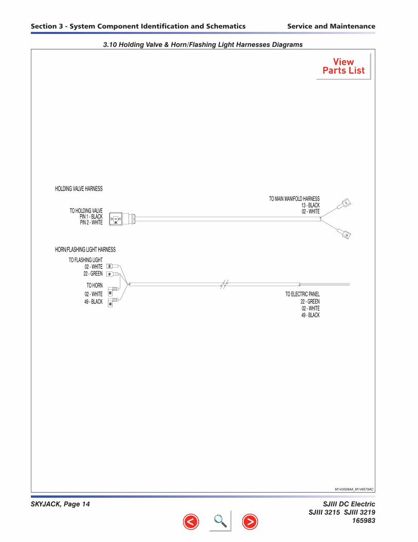
SKYJACK, Page 14 SJIII DC ElectricSJIII 3215 SJIII 3219
165983
Service and MaintenanceSection 3 - System Component Identification and Schematics
13B
13
234
111109
12DEUTSCH
PIN 1 - 17A (BLACK)
PIN 3 - 19 (BLACK)PIN 4 - 19A (BLACK/WHITE)
PIN 2 - 21 (BLACK/WHITE) PIN 8 - 71 (BLACK/WHITE)
PIN 6 - 13A (BLACK/WHITE)PIN 5 - 13 (BLACK)
PIN 7 - 19 (BLACK)
65
78
PIN 11 - N/UPIN 12 - N/U
PIN 10 - 13B (BLUE)PIN 9 - 13 (BROWN)
BLACK/WHITE
17A
21NCNO
BLUE
BROWN BLACK
19NC
BLACK
NO
BROWN
BLACK/WHITE
19A
BROWN BLACK
BLUE
NO
BROWN
71NC
BLACK
BLUE
BLACK/WHITE
19
NO
BLUE
NC
BLACK/WHITE
13A
13
LS1B
LS1A
LS7
LS6
LS1B
LS1A
LS6
LIMIT SWITCH ASSEMBLY - Model 3215
LIMIT SWITCH ASSEMBLY - Model 3219
13B
13
7
DEUTSCH 8
234
1
65
109
1112
PIN 7 - 19 (BLACK)PIN 8 - 71 (BLACK/WHITE)
PIN 6 - N/UPIN 5 - N/U
PIN 3 - 19 (BLACK)
PIN 1 - 17A (BLACK)
PIN 4 - 19A (BLACK/WHITE)
PIN 2 - 21 (BLACK/WHITE)
PIN 10 - 13B (BLUE)PIN 9 - 13 (BROWN)
PIN 11 - N/UPIN 12 - N/U
BLACK
NC
BLACK/WHITE
BROWN
NO
BLACK/WHITEBLUE
19BLACK
71NC
19
19ABLACK/WHITE
NO
BROWN
NCNO
BROWN
BLUE
BLACK
BLUE
21
17A
13 - BLACKTO MAIN MANIFOLD HARNESS
02 - WHITE
PIN 2 - WHITEPIN 1 - BLACK
TO HOLDING VALVE
13B
02
HOLDING VALVE HARNESS
HORN/FLASHING LIGHT HARNESS
49
02
02
2202 - WHITE22 - GREEN
TO FLASHING LIGHT
TO HORN
49 - BLACK02 - WHITE
49 - BLACK
22 - GREEN02 - WHITE
TO ELECTRIC PANEL
M143508AA_M146578AC
3.10 Holding Valve & Horn/Flashing Light Harnesses Diagrams

SJIII DC ElectricSJIII 3215 SJIII 3219165983
SKYJACK, Page 15
Section 3 - System Component Identification and SchematicsService and Maintenance
LS7
LIMIT SWITCH ASSEMBLY - Model 3219
PIN 7 - N/UPIN 6 - 13B (BLUE)PIN 5 - 13 (BROWN)
PIN 8 - N/U
PIN 2 - 21 (BLACK/WHITE)
PIN 4 - 13A (BLACK/WHITE)PIN 3 - 13 (BLACK)
PIN 1 - 71 (BLACK)
13
13A
71
21
13
13B
LS7
LS1B 76
823
1
54
DE
UTS
CH
BROWN BLACK
NO
BLUE BLACK/WHITE
NC
BLUE
BROWN
BLACK/WHITE
BLACK
NO NC
LIMIT SWITCH ASSEMBLY - Model 3215
BLACK
NC
BROWN
BLUE
NO
BLACK/WHITE
LS1B
DE
UTS
CH4 5
1
32
8
67
71
21
13
13B
PIN 1 - 71 (BLACK)
PIN 3 - N/UPIN 4 - N/U
PIN 2 - 21 (BLACK/WHITE)
PIN 8 - N/U
PIN 5 - 13 (BROWN)PIN 6 - 13B (BLUE)PIN 7 - N/U
LS1B
LS1B
M159354AC_M159355SC-KC2
3.11 Limit Switch Assemblies Diagrams

SKYJACK, Page 16 SJIII DC ElectricSJIII 3215 SJIII 3219
165983
Notes

SKYJACK, Page 17SJIII DC ElectricSJ3215 SJ3219165983
A B C D E F G H
V
Z
Y
X
W
3.12 Hydraulic Schematic (Models 3215 & 3219)
M
AP
BT
AP
BT
PS1PRESSURESWITCH
ORIFICEF1RETURNFILTER
PUMP
HYDRAULIC TANK
P1 CYLINDERC4 BRAKE
.051 DIA. 2H-25
VALVECUSHION
CB1
VALVECOUNTERBALANCE
RELIEFSYSTEMR1
VALVE
VALVE
O4BRAKE
PORTPLUGGED 3H-17
BRAKE
4H-16
DRIVEVALVE
FORWARD
4H-15REVERSE
VALVEDRIVE
MB3
ORIFICECUSHION
.040 DIA.
CUSHION
BLOCKVALVE
V1EMERGENCYLOWERINGVALVE
MB5
BLOCKVALVELOWERING
BLOCKMANIFOLDVALVEDECELERATION
MB4
MANIFOLDVALVE
BLOCK
HOLDING
O3
4H-24
VALVESTEERLEFT
4H-23RIGHT
VALVESTEER
MAIN MANIFOLD BLOCK
LIFTVALVE
MB1
3H-14A
2H-13
VALVELOWERING
MB10
O5STEERINGORIFICE.040 DIA.
O5STEERINGORIFICE.040 DIA.
C3
L
STEERCYLINDER
R
DECELERATION VALVE
R2
RELIEFVALVE
LIFT
HOLDINGVALVE
2H-13-1
2H-13A
ORIFICE .040 DIA.
O6 EMER. LOWERING
LIFT
ORFICE .067 DIA.
CYLINDER
C2
PORT A
PORT BDRIVEMOTOR
LEFT
RIGHTPORT A
PORT B MOTORDRIVE
VALVE MANIFOLDBLOCK
FREE-WHEELING FRONT AXLE
O7DRIVEORIFICE.024 DIA.
.063 DIA. (3219 ONLY)ORIFICE
O2LOWERING
(3215 ONLY)
M163550AB

SJIII DC ElectricSJ3215 SJ3219
165983
SKYJACK, Page 18
A B C D E F G H
V
Z
Y
X
W
3.13 Main Manifold Harness
M163547AA
00
BATTERY (-)00 - GREEN/YELLOW
(14 AWG)
13B
RIGHT
FORWARD VALVEBLACK HEIRSHMANPIN 1 - 16 WHITE/BLACKPIN 2 - 02 WHITE
REVERSE VALVEGREY HEIRSHMANPIN 1 - 15 BLUEPIN 2 - 02 WHITE
16
0215
02 REVERSE
02
24
LEFT
0223
INSERT ORIENTATIONBOTTOM VIEW
FORWARD
0202
02
13C
LOWERING VALVE13B - ORANGE02 - WHITE
SOFT STOP VALVE13C - ORANGE02 - WHITE
02
0214LIFT VALVE14 - BLACK02 - WHITE
17
02
SPLICE #1
02
BRAKE VALVE17 - BLUE/RED02 - WHITE
CUSHION VALVE25 - ORANGE/GREEN
02 - WHITE
25
13B HOLDING VALVE13B - ORANGE (18 AWG)
02 - WHITE (18 AWG)
02
SPLICE #2
RIGHT STEER VALVEBLACK HEIRSHMANPIN 1 - 23 BLACK/WHITEPIN 2 - 02 WHITE
LEFT STEER VALVEGREY HEIRSHMANPIN 1 - 24 BLUE/BLACKPIN 2 - 02 WHITE
TO ELECTRIC PANEL - 14 WIRES
00 - WHITE (14 AWG)02 - WHITE03 - BLUE (14 AWG)13 - ORANGE13A - ORANGE14 - BLACK15 - BLUE16 - WHITE/BLACK17 - BLUE/RED19B - WHITE/RED23 - BLACK/WHITE24 - BLUE/BLACK25 - ORANGE/GREEN59L - ORANGE/BLACK
03
59L
19B
02
19B
GREY
BLACK
BLAC
K
GREY

SKYJACK, Page 19SJIII DC ElectricSJ3215 SJ3219165983
A B C D E F G H
V
Z
Y
X
W
3.14 Electrical Panel Diagram
M163503AB
1000
uF
49
02
71 - BLACK72 - BLACK/WHITEBATTERY TRAY
72 - BLACK/WHITEHYDRAULIC TRAY
19 - BLACK
(63")
(43")
13BCR 28CR 17ACR 17CR 21ACR
0213B
13C
82
0228
28A
19
0217A 021725
17B
0217 17A
7A
0221A 59E
59B
02
59B
14 59A
59
02
59C
14 59D
7A
02 02 07 07A 8C 13 13A 14 14E 19 19A 14 59I59J59H59H59G59G597221A49 21 15 16
19A 02
17 17 71 23 24
02
17CR1 14CR 14CR159JCR
D23 D24
19A
29
D13-1D28A D13
17B17C
17D
D17D-2
59F
R RR R R
D15 D1
6
D17-
1
59H59J
59G
59I
02
R
D21
02
8282 2929
02 02
02
29
D14E-2 D17D-1D21-
1
D19A
D14E
D14
22
02
3A
BLUE
YELLOW
TO MAIN MANIFOLD
PIN 4 - N/U
TO HORN
49 - BLACK02 - WHITE
02 - WHITE22 - GREEN
TO FLASHING LIGHT
PIN 3 - 02 (WHITE)
PIN 1 - 19 (BLACK)PIN 2 - 28 (GREEN)
TO TILT SWITCH
HORN/FLASHING LIGHTTILT SWITCH
MAIN MANIFOLD
PLATFORM CONTROL BOX
REAR HARNESS22
PIN 3 - 82 WHITE (NO)
PIN 1 - 19A BLACK (COM)PRESSURE SWITCH
PIN 2 - 19B GREEN (NC)
PRESSURE SWITCH 8282
13B
19A19B
19
82
19B
19A
3A00
03
19B
19B
22
0003 25
PIN 87 - N/UPIN 87a - 13C
PIN 30 - 82ALARM CUTOUT RELAY
PIN 85 - 02PIN 86 - 13B
13BCR
PIN 87 - 19APIN 87a - 28A
PIN 30 - 19TILT SWITCH RELAY
PIN 85 - 02PIN 86 - 28
28CR
PIN 87 - 25PIN 87a - N/U
PIN 30 - 17BCUSHION RELAY
PIN 85 - 02PIN 86 - 17A
17ACR
PIN 87 - N/UPIN 87a - 17C
PIN 30 - 17DSTEER RELAY
PIN 85 - 02PIN 86 - 17
17CR
PIN 87 - 59EPIN 87a - 59F
PIN 30 - 59BHIGH SPEED RELAY
PIN 85 - 02PIN 86 - 21A
21ACR
PIN 87 - 59APIN 87a - 59B
PIN 30 - 59LIFT SPEED RELAY
PIN 85 - 02PIN 86 - 14
14CR
PIN 87 - 59DPIN 87a - 59C
PIN 30 - 7ALIFT SPEED RELAY 2
PIN 85 - 02PIN 86 - 14
14CR1
PIN 87 - 59HPIN 87a - 59G
PIN 30 - 59IBASE CONTROL RELAY
PIN 85 - 02PIN 86 - 59J
59JCR
PIN 87 - 17APIN 87a - 17B
PIN 30 - 7ATRANSFER RELAY
PIN 85 - 02PIN 86 - 17
17CR1
28
RST2
RST3
RST4
RST5
RST6
RST7
R
RST8
TO BATTERY
TO POWER DECK
TO END OF STROKE
TO TILT SWITCH
TO LOWER KEYSWITCH BOX
TO HIGH SPEED LIMIT SWITCH
SOLENOID CABLESTO OUTRIGGER
TO REAR MANIFOLD
TO MAIN MANIFOLD
TO TERMINAL BLOCK
TO JOYSTICK BOX
TO ENGINE
LEGEND:
TO FLASHER TO HORN/FLASHING LIGHT
EUROPE WIRE NUMBER21B60
N.AWIRE NUMBER21B7A
CONTROL CABLE OPTIONS
WIRE COLOURGREEN/BLACK
RED/WHITE
11
10
9 1
2
3
16
15
13
14
12 4
5
6
8
7
FRONT VIEW
(NOT USED)
WHITE BLACK (16)
RED WHITE (OPT)
GREEN BLACK (OPT)
ORANGE BLACK (59)
RED BLACK (18)
BLUE BLACK (24)
BLACK WHITE (23)157(49) GREEN WHITE
(8C) BLUE WHITE
(07) RED
(14) BLACK
(15) BLUE
(02) WHITE
(13) ORANGE
14
13
12
11
10
9
6
5
4
3
2
1
(7A) GREEN
MALE
8 16
BACK VIEW
DEUTSCH
2 43
DEUTSCH
1 3 42 1
7 566 578 8
PIN 3 - 13 (ORANGE)PIN 4 - 14E (BLACK)
PIN 1 - 07 (RED)PIN 2 - 3A (BLUE)
PIN 1 - 71 (BLUE/BLACK)PIN 2 - 21 (GREEN/BLACK)PIN 3 - 13 (ORANGE)PIN 4 - 13A (GREEN/WHITE) BACK VIEWPIN 8 - N/U
PIN 7 - N/UPIN 6 - 13B (RED/BLACK)PIN 5 - 13 (ORANGE)
PIN 7 - 7A (GREEN)PIN 8 - 02 (WHITE)
PIN 5 - N/UPIN 6 - 8C (WHITE/BLACK)
TO HIGH SPEED LIMITSTO SOFT STOP LIMIT SWITCH
TO CHARGER CUTOUTTO LOWER BASE CTRL
TO FLASHER

SJIII DC ElectricSJ3215 SJ3219
165983
SKYJACK, Page 20
A B C D E F G H
V
Z
Y
X
W
H1HORN
2202
24V
02 - WHITE22 - GREEN
FL-22FLASHING LIGHT
234
1
DEUTSCH
PIN 1 - 19 (BLACK)PIN 2 - 28 (GREEN)PIN 3 - 02 (WHITE)
PIN 4 - N/U
TS1TILT SWITCH (ANSI/CSA)
FROM ELEC. PANELBLACK - 22WHITE - 02 (ANSI - FEM. TERM.)
HORN/FLASHING LIGHT HARNESS
DUAL FLASHING LIGHT HARNESS
22
02
02
49
22
WHITE - 02BLACK - 22
02
22
02
WHITE - 02BLACK - 22
02
22
02
WHITE - 02 (CE - RING TERM.)
3.15 Horn/Tilt Switch/Flashing Light Diagram
M146648AA_S3a

SKYJACK, Page 21SJIII DC ElectricSJ3215 SJ3219165983
A B C D E F G H
V
Z
Y
X
W
3.16 Electrical Schematic (Equipped with all options)
M163179AC
42
40
41
39
38
36
35
37
32
34
33
31
30
29
28
26
27
24
23
22
20
19
21
25
16
18
17
15
13
14
12
10
11
7
6
8
9
3
5
4
2
1
44
43
-NEGATIVE
45
46
47
48
49
50
51
52
53
54
55
HORN
POWER ON LED
LEFT SOLENOID
RIGHT SOLENOID
FORWARD SOLENOID
STEER RELAY
BRAKE SOLENOID
REVERSE SOLENOID
TRANSFER RELAY
DOWN SOLENOID
HOLDING VALVE
FLASHING LIGHTOPTION
FLASHER
TIMER
15A CIRCUIT
INVERTER OPTION
BREAKER
INVERTER OPTION
PUMP MOTOR
PACKBATTERY
CHARGER
B4 6VBATTERY
B3 6VBATTERY
B2 6VBATTERY
B1 6VBATTERY
F1300AFUSE 00
L1CRCHARGER
CUTOUT RELAY
24V CHARGER
24V
110 VACLINE VOLTAGE
BC
B-
M-
B+
ENABLE
SPEED
MC1
MOTORCONTACTOR
00CB1
02
CB2
15A CIRCUITBREAKER
033A
S1 MAINDISCONNECT
F2
50A FUSE
05
STOPSWITCH
S28EMERGENCY
5A
027A
19B
85
TIMER
7A
POWER ON LIGHTLED-2
02
NO
10E 7A
5A07
NCHO
NCHO
078C
(IN IDLE POSITION)
IDLE/PLTF/BASEKEY SWITCH
S10
5A
HORNH1
49
02
BLUE/BLACK
BLACK/WHITE
BLUE
WHITE/BLACK
WHITE
24
23
16
15
59ORANGE/BLACK
ENABLE
JOYSTICK PCB
08
S7JOYSTICK
0-5V DC 59
24
23
RIGHT 12B
S7-2
LEFTS7-3
S7-1NUETRAL
OUTPUT
02
S7-6ENABLE 8A
12B
S27TORQUESWITCH
16
12B
8A
15
13
14
A
B
S3LIFT/OFF/DRIVE
SWITCH
FWD/UP
AREV/DN
B
59
15
16
23
24
02
GREEN
BLUE/WHITE
RED/WHITE
BLACK
ORANGE
RED
GREEN/WHITE
RED/BLACK
49
7A
08
S4EMERGENCY
STOP
S8HORN
SWITCH
08
07
8C
08
02
02
BATTERY CHARGE
002.7K OHMS
RST1
BCI
INDICATOR
V02
18
CRD3CRD1 CRD2
02 60
POWER ON/LSSLIGHT
LED-1
02
14
13 13
14
6060
49 49
7A 7A
07
8C 8C
07
BASE LIFT RESISTOR
STEER ONLY RESISTOR
LIFT SPEED RELAY 2
LIFT SPEED RELAY
PLATFORM LIFT RESISTOR
ELEVATED DRIVE RESISTOR
HIGH SPEED RESISTOR
VOLTAGE DIVIDER RESISTOR
BASE CONTROL RELAY
HIGH SPEED RELAY
59I
19B
BASECONTROL BOX
14E
1310E
S2UP/DOWN
SWITCH
13 13ALS7
22
FL-22FLASHER
FL-2922 29
2H-13A
13
13
13C
D13 29
82D13-1
29
D19A
28AD28A
BP-29
C2
29
3H-14A
82BP-82
C3
2H-1313
DO2-1
2H-13-1
0200
19
19
PS1
19A
82
82
19B
TS1
28CR28
19
19ATT
19A
LS471
POTHOLE PROTECTIONLIMIT SWITCHES N.C.H.O.
72LS519
71 21
LS1B
HIGH SPEEDLIMIT SWITCHES N.C.
21A
D21
D21-1 17B
7A 17A
25
17ACR
C1
2H-25
D14D14E-1
14
D14E-2
13BCR13B
59A59
59 59B
14CR14 02
07A 59C
59D07A
RST468 OHM
RST52.2K OHM
RST61.2K OHM
14CR1
14 02
02
RST7270 OHM
59G
59H 59I
59J
59B 59E
59B 59F
RST2100 OHM
RST3750 OHM
DO2-8
4H-16DO2-7
DO2-6
4H-15
3H-17
D16
D15
1717CR
17
D24
D2317D17C
4H-24
DO2-9
DO2-10
4H-23
17
17 17
02
0202
02
24
23
16
15
59J
D17D-1
D17D-2
17CR1
D17-1
MOTOR CONTROLLER
DECELERATIONSOLENOID (3215 ONLY)
CUT-OUT RELAYLOWERING ALARM
OVERLOAD PRESS. SW.
MOTION/TILT BEEPER
MOTOR CONTACTOR
0.47uF CAPACITOR
OVERLOAD BEEPER
0.47uF CAPACITOR
UP SOLENOID
HOURMETER
TILT SWITCH
TILT SWITCH RELAY
CUSHION RELAY
CUSHION SOLENOID
1000uF CAPACITOR
21ACR
59JCR
RST81.5 OHM
DO2-3
DO2-2
DO2-5
DO2-4

SJIII DC ElectricSJ3215 SJ3219
165983
SKYJACK, Page 22
Notes

SJIII DC ElectricSJIII 3215 SJIII 3219165983
SKYJACK, Page 1
4
Section 4TROUBLESHOOTING INFORMATION
Table of Contents
Introduction ................................................................................................................................................... 3
Electrical System4.1-1 All Controls Inoperative ..................................................................................................................... 44.1-2 All Controls Except for Down Function Inoperative ......................................................................... 54.1-3 All Controls Inoperative From Base Control Console ...................................................................... 54.1-4 No Up Function from Base Control Console .................................................................................... 54.1-5 Up Function Slow from Base Control Console ................................................................................ 64.1-6 No Down Function from Base Control Console ............................................................................... 64.1-7 All Controls Inoperative From Platform Control Console ................................................................. 74.1-8 No Up Function from Platform Controls .......................................................................................... 74.1-9 Up Function Slow from Platform Control Console ........................................................................... 84.1-10 No Down Function from Platform Controls ...................................................................................... 84.1-11 Steer Only Inoperative ...................................................................................................................... 94.1-12 Right Steer Inoperative ................................................................................................................... 94.1-13 Left Steer Inoperative .................................................................................................................... 104.1-14 Drive Only Inoperative..................................................................................................................... 104.1-15 No Drive or Steer when Platform Elevated ..................................................................................... 104.1-16 Platform Drives in Slow Speed Only ............................................................................................... 114.1-17 Brake will not Release .................................................................................................................... 114.1-18 Forward Drive Function Inoperative ................................................................................................ 114.1-19 Reverse Drive Function Inoperative ................................................................................................ 11
Hydraulic System4.2-1 All Function Inoperative .................................................................................................................. 124.2-2 All System sluggish ......................................................................................................................... 124.2-3 Platform Drifts Down ....................................................................................................................... 124.2-4 Platform Lifts Slowly ........................................................................................................................ 124.2-5 Platform does not Lift ...................................................................................................................... 124.2-6 Platform will not Lower .................................................................................................................... 124.2-7 Platform Lowers Slowly (3215 only) ............................................................................................... 134.2-8 Platform Drives Slow ....................................................................................................................... 134.2-9 Platform will not Drive in Forward or Reverse ................................................................................ 134.2-10 Brake(s) will not Release ............................................................................................................... 134.2-11 Platform does not Steer .................................................................................................................. 13

SKYJACK, Page 2 SJIII DC ElectricSJIII 3215 SJIII 3219
165983
Notes

SJIII DC ElectricSJIII 3215 SJIII 3219165983
SKYJACK, Page 3
Section 4 - Troubleshooting Information Service and Maintenance
Introduction
The following pages contain a table of Troubleshooting Information for locating and correcting most service trouble which can develop. Careful and accurate analysis of the systems listed in the table of Troubleshooting Information will localize the trouble more quickly than any other method. This manual cannot cover all possible troubles and deficiencies that may occur. If a specific trouble is not listed, isolate the major component in which the trouble oc-curs, isolate whether the problem is electrical or hydraulic, and then isolate and correct the specific problem.
The content of this section is separated into “probable cause” and “remedy.” The information preceded by a number represents the “probable cause.” The following line, noted by a dash, represents the “remedy” to the “probable cause” directly above it. See example below for clarification.
1. Probable Cause - Remedy

SKYJACK, Page 4 SJIII DC ElectricSJIII 3215 SJIII 3219
165983
Section 4 - Troubleshooting Information Service and Maintenance
Electrical System
4.1-1 All Controls Inoperative1. Battery charger plugged into external power source.
- Disconnect charger cord.2. Batteries disconnected.
- Connect batteries.3. Dirty or loose battery terminals.
- Clean and tighten connections.4. Battery charge low.
- Check each cell with a hydrometer. Reading should be 1.275 (fully charged). Recharge if low reading. Replace if reading difference between cells is 0.050.
5. Main battery cables open or defective. - Check continuity. Replace if defective.
6. Fuse F1 defective. - Replace fuse.
7. Main battery disconnect switch S1 open or defective. - Close switch. Check continuity. Replace if defective.
8. Loose or broken wire #3 from motor contactor C1 to circuit breaker CB2. - Check continuity. Replace if defective.
9. Defective or tripped circuit breaker CB2. - Reset circuit breaker. Replace if defective.
10. Loose or broken wire #3A from circuit breaker CB2 to charger relay L1CR. - Check continuity. Replace if defective.
11. Defective battery charger relay L1CR. - Check relay. Replace if defective.
12. Loose or broken wire #5 from charger relay L1CR to base emergency stop switch S28. - Check continuity. Replace if defective.
13. Open or defective base emergency stop switch S28. - Close switch. Check switch. Replace if defective.
14. Loose or broken wire #5A from base emergency stop switch S28 to base key switch S10. - Check continuity. Replace if defective.
15. Open or defective base key switch S10. - Select function with switch. Check switch. Replace if defective.
16. Loose or broken wire #07 from base key switch S10 to base terminal block. - Check continuity. Replace if defective.
17. Loose or broken wire #07 from base terminal block to platform emergency stop switch S4. - Check continuity. Replace if defective.
18. Open or defective platform emergency stop switch S4. - Close switch. Replace if defective.
19. Loose or broken wire #7A from platform emergency stop switch S4 to base terminal block. - Check continuity. Replace if defective.
20. Loose or broken wire #7A from base terminal block to base key switch S10. - Check continuity. Replace if defective.
21. Open or defective base key switch S10. - Close switch. Replace if defective.
22. Loose or broken wire #00 from motor controller to circuit breaker CB1. - Check continuity. Replace if defective.
23. Defective or tripped circuit breaker CB1. - Reset circuit breaker. Replace if defective.
24. Loose or broken wire #02 from circuit breaker CB1 to base terminal block. - Check continuity. Replace if defective.
Electrical System

SJIII DC ElectricSJIII 3215 SJIII 3219165983
SKYJACK, Page 5
Section 4 - Troubleshooting Information Service and Maintenance
Electrical System (Continued)
4.1-2 All Controls Except for Down Function Inoperative 1. Loose or broken wire #59I from base terminal block to motor controller.
- Check continuity. Replace if defective.2. Loose or broken wire #19 from base terminal block to tilt relay 28CR.
- Check continuity. Replace if defective.3. Loose or broken wire #19A from tilt relay 28CR to base terminal block.
- Check continuity. Replace if defective.4. Loose or broken wire #19A from base terminal block to pressure switch PS1.
- Check continuity. Replace if defective.5. Defective pressure switch PS1.
- Check continuity through switch. Replace if defective.6. Loose or broken wire #19B from pressure switch PS1 to motor contactor C1.
- Check continuity. Replace if defective.7. Loose or broken wire #19B from base terminal block to motor controller.
- Check continuity. Replace if defective.8. Defective resistor RST7. (With joystick fully stroked)
- Check resistor and make sure it is secure. Replace if defective.9. Loose or broken B- cable from batteries to B- lug on motor controller.
- Check continuity. Replace if defective.10. Loose or broken B+ cable from main battery disconnect switch S1 to motor contactor C1.
- Check continuity. Replace if defective.11. Loose or broken B+ cable from motor contactor C1 to motor DCM1.
- Check continuity. Replace if defective.12. Loose or broken B+ cable from motor DCM1 to B+ lug on motor controller.
- Check continuity. Replace if defective.13. Loose or broken B- cable from motor DCM1 to M- lug on motor controller.
- Check continuity. Replace if defective.14. Defective motor controller.
- Check motor controller input and output voltage. Replace if defective.15. Defective motor DCM1.
- Check motor for operation with 24 volt supply. Replace if defective.
4.1-3 All Controls Inoperative From Base Control Console1. Loose or broken wire #7A from base terminal block to base key switch S10.
- Check continuity. Replace if defective.2. Loose or broken wire #10E from base key switch S10 to base up/down switch S2.
- Check continuity. Replace if defective.
4.1-4 No Up Function from Base Control Console1. Defective up/down switch S2.
- Check switch. Replace if defective.2. Loose or broken wire #14E from up/down switch S2 to base terminal block.
- Check continuity. Replace if defective.3. Open or defective diode D14E-1.
- Check diode. Replace if defective.4. Open or defective diode D14E-2.
- Check diode. Replace if defective.5. Open diode D14A.
- Check diode. Replace if defective.

SKYJACK, Page 6 SJIII DC ElectricSJIII 3215 SJIII 3219
165983
Section 4 - Troubleshooting Information Service and Maintenance
Electrical System (Continued)
6. Loose or broken wire #14 from base terminal block to relay 14CR. - Check continuity. Replace if defective.
7. Loose or broken wire #14 from relay 14CR to relay 14CR1. - Check continuity. Replace if defective.
8. Defective low voltage protection resistor RST8. - Check resistor and make sure it is secure. Replace if defective.
9. Loose or broken wire #14B from base terminal block to up valve coil 3H-14B. - Check continuity. Replace if defective.
10. Loose or broken wire #02 from base terminal block to up valve coil 3H-14B. - Check continuity. Replace if defective.
11. Defective up valve coil 3H-14B. - Check continuity through coil. Replace if defective.
12. Machine not level. (Above high speed limit switch) - Use on level surface.
13. Loose or broken wire #59J from base terminal block to base control relay 59JCR. - Check continuity. Replace if defective.
14. Loose or broken wire #02 from base terminal block to base control relay 59JCR. - Check continuity. Replace if defective.
15. Defective base control relay 59JCR. - Check relay. Replace if defective.
16. Loose or broken wire #7A from base terminal block to lift speed relay 14CR1. - Check continuity. Replace if defective.
17. Loose or broken wire #59D from lift speed relay 14CR1 to base terminal block. - Check continuity. Replace if defective.
18. Defective base lift resistor RST6. - Check resistor and make sure it is secure. Replace if defective.
19. Loose or broken jumper wire #59H at base terminal block. - Check continuity. Replace if defective.
20. Loose or broken wire #59H from base terminal block to base control relay 59JCR. - Check continuity. Replace if defective.
4.1-5 Up Function Slow from Base Control Console1. Loose or broken wire #14 from base terminal block to lift speed relay 14CR1.
- Check continuity. Replace if defective.2. Loose or broken wire #02 from base terminal block to lift speed relay 14CR1.
- Check continuity. Replace if defective.3. Defective lift speed relay 14CR1.
- Check relay. Replace if defective.
4.1-6 No Down Function from Base Control Console
NOTEDown function is not proportionally controlled.
1. Defective up/down switch S2. - Check switch. Replace if defective.
2. Loose or broken wire #13 from up/down switch S2 to base terminal block. - Check continuity. Replace if defective.
3. Loose or broken wire # 13 from base terminal block to down valve 2H-13 or holding valve 2H-13-1. - Check continuity. Replace if defective.

SJIII DC ElectricSJIII 3215 SJIII 3219165983
SKYJACK, Page 7
Section 4 - Troubleshooting Information Service and Maintenance
Electrical System (Continued)
4. Defective down valve coil 2H-13. - Check continuity through coil. Replace if defective.
5. Defective lift cylinder holding valve coil 2H-13-1. - Check continuity through coil. Replace if defective.
6. Loose or broken wire #02 from holding valve coil 2H-13-1 or down valve coil 2H-13 to base terminal block.
- Check continuity. Replace if defective.
4.1-7 All Controls Inoperative From Platform Control Console1. Loose or broken wire #8C from base key switch S10 to base terminal block.
- Check continuity. Replace if defective.2. Loose or broken wire #8C or wire #02 from base terminal block to platform emergency stop switch
S4. - Check continuity. Replace if defective.
3. Open or defective platform emergency stop switch S4. - Close switch. Replace if defective.
4. Loose or broken wire #8 or wire #02 from emergency stop switch S4 to battery charge indicator BCI. - Check continuity. Replace if defective.
5. Loose or broken wire #8 or wire #02 from battery charge indicator BC1 to joystick S7. - Check continuity. Replace if defective.
6. Defective joystick enable switch S7-6. - Check switch. Replace if defective.
7. Defective joystick neutral switch S7-1. - Check switch. Replace if defective.
8. Defective joystick S7. - Check joystick. Replace if defective.
4.1-8 No Up Function from Platform Controls 1. Loose or broken wire “B” from proportional controller S7 to lift/drive switch S3.
- Check continuity. Replace if defective.2. Lift/Drive switch S3 defective.
- Check switch. Replace if defective.3. Defective PWM card on joystick S7.
- Check joystick card. Replace if defective.4. Loose or broken wire #14 from lift/drive switch S3 to base terminal block.
- Check continuity. Replace if defective.5. Open or defective diode D14A.
- Check diode. Replace if defective.6. Loose or broken wire #14 from base terminal block to relay 14CR.
- Check continuity. Replace if defective.7. Defective low voltage protection resistor RST8.
- Check resistor and make sure it is secure. Replace if defective.8. Loose or broken wire #14A from base terminal block to up valve coil 3H-14A.
- Check continuity. Replace if defective.9. Loose or broken wire #02 from base terminal block to up valve coil 3H-14A.
- Check continuity. Replace if defective.10. Defective up valve coil 3H-14A.
- Check continuity through coil. Replace if defective.

SKYJACK, Page 8 SJIII DC ElectricSJIII 3215 SJIII 3219
165983
Section 4 - Troubleshooting Information Service and Maintenance
Electrical System (Continued)
11. Machine not level. (Above high speed limit switch) - Use on level surface.
12. Defective base control relay 59JCR. - Check relay. Replace if defective.
13. Defective lift speed relay 14CR. - Check relay. Replace if defective.
14. Loose or broken wire #59 from base terminal block to lift speed relay 14CR. - Check continuity. Replace if defective.
15. Loose or broken wire #59A from lift speed relay 14CR to base terminal block. - Check continuity. Replace if defective.
16. Defective platform lift resistor RST6. - Check resistor and make sure it is secure. Replace if defective.
17. Loose or broken jumper wire #59G at base terminal block. - Check continuity. Replace if defective.
18. Loose or broken wire #59G from base terminal block to base control relay 59JCR. - Check continuity. Replace if defective.
4.1-9 Up Function Slow from Platform Control Console1. Loose or broken wire #14 from base terminal block to lift speed relay 14CR.
- Check continuity. Replace if defective.2. Loose or broken wire #02 from base terminal block to lift speed relay 14CR.
- Check continuity. Replace if defective.3. Defective lift speed relay 14CR.
- Check relay. Replace if defective.
4.1-10 No Down Function from Platform Controls1. Loose or broken wire “A” from proportional controller S7 to lift/drive switch S3.
- Check continuity. Replace if defective.2. Lift/Drive switch S3 defective.
- Check switch. Replace if defective.3. Defective PWM card on joystick S7.
- Check joystick card. Replace if defective.4. Loose or broken wire #13 from lift/drive switch S3 to base terminal block.
- Check continuity. Replace if defective.5. Loose or broken wire # 13 from base terminal block to down valve 2H-13 or holding valve 2H-13-1.
- Check continuity. Replace if defective.6. Defective down valve coil 2H-13.
- Check continuity through coil. Replace if defective.7. Defective lift cylinder holding valve coil 2H-13-1.
- Check continuity through coil. Replace if defective.8. Loose or broken wire #02 from holding valve coil 2H-13-1 or down valve coil 2H-13 to base terminal
block. - Check continuity. Replace if defective.

SJIII DC ElectricSJIII 3215 SJIII 3219165983
SKYJACK, Page 9
Section 4 - Troubleshooting Information Service and Maintenance
Electrical System (Continued)
4.1-11 Steer Only Inoperative1. Loose or broken wire #8A from proportional controller S7 to lift/off/drive switch S3.
- Check continuity. Replace if defective.2. Lift/Off/Drive switch S3 defective.
- Check switch. Replace if defective.3. Loose or broken wire #12B from steer switches S7-2 and S7-3 to lift/off/drive switch S3.
- Check continuity. Replace if defective.4. Loose or broken wire #17C from base terminal block to relay 17CR.
- Check continuity. Replace if defective.5. Defective relay 17CR.
- Check relay. Replace if defective.6. Loose or broken wire #17D from relay 17CR to base terminal block.
- Check continuity. Replace if defective.7. Open diode D17D-1.
- Check diode. Replace if defective.8. Open diode D17D-2.
- Check diode. Replace if defective.9. Defective lift speed relay 14CR1.
- Check relay. Replace if defective.10. Loose or broken wire #59C from 14CR1 lift speed relay to base terminal block.
- Check continuity. Replace if defective.11. Defective steer only resistor RST5.
- Check resistor and make sure it is secure. Replace if defective.
4.1-12 Right Steer Inoperative 1. Defective right steer switch S7-2.
- Check switch. Replace if defective.2. Loose or broken wire #23 from right steer switch S7-2 to base terminal block.
- Check continuity. Replace if defective.3. Loose or broken wire #23 from base terminal block to steer right valve coil 4H-23.
- Check continuity. Replace if defective.4. Defective steer right valve coil 4H-23.
- Check continuity through coil. Replace if defective.5. Loose or broken wire #02 from steer right valve coil 4H-23 to base terminal block.
- Check continuity. Replace if defective.6. Open diode D23.
- Check diode. Replace if defective.

SKYJACK, Page 10 SJIII DC ElectricSJIII 3215 SJIII 3219
165983
Section 4 - Troubleshooting Information Service and Maintenance
Electrical System (Continued)
4.1-13 Left Steer Inoperative 1. Defective left steer switch S7-3.
- Check switch. Replace if defective.2. Loose or broken wire #24 from right steer switch S7-3 to base terminal block.
- Check continuity. Replace if defective.3. Loose or broken wire #24 from base terminal block to steer left valve coil 4H-24.
- Check continuity. Replace if defective.4. Defective steer left valve coil 4H-24.
- Check continuity through coil. Replace if defective.5. Loose or broken wire #02 from steer left valve coil 4H-24 to base terminal block.
- Check continuity. Replace if defective.6. Open diode D24.
- Check diode. Replace if defective.
4.1-14 Drive Only Inoperative1. Open or defective diode D17-1.
- Check diode. Replace if defective.2. Loose or broken wire #59B from lift speed relay 14CR to high speed relay 21CR.
- Check continuity. Replace if defective.3. Defective relay 14CR.
- Check relay. Replace if defective.
4.1-15 No Drive or Steer when Platform Elevated1. Pothole protection bars not fully lowered.
- Clear obstructions. Repair as needed.2. Loose or broken wire #71 from base terminal block to pothole protection limit switch LS4.
- Check continuity. Replace if defective.3. Defective pothole protection limit switch LS4.
- Check switch. Replace if defective.4. Loose or broken wire #72 from pothole protection limit switch LS4 to base terminal block.
- Check continuity. Replace if defective.5. Loose or broken wire #72 from base terminal block to pothole protection limit switch LS5.
- Check continuity. Replace if defective.6. Defective pothole protection limit switch LS5.
- Check switch. Replace if defective.7. Loose or broken wire #19 from pothole protection limit switch LS5 to base terminal block.
- Check continuity. Replace if defective.

SJIII DC ElectricSJIII 3215 SJIII 3219165983
SKYJACK, Page 11
Section 4 - Troubleshooting Information Service and Maintenance
Electrical System (Continued)
4.1-16 Platform Drives in Slow Speed Only1. Loose or broken wire #71 from base terminal block to high speed limit switch LS1B.
- Check continuity. Replace if defective.2. Open or defective high speed limit switch LS1B.
- Check switch. Replace if defective.3. Loose or broken wire #21 from high speed limit switch LS1B to base terminal block.
- Check continuity. Replace if defective.4. Open diode D21.
- Check diode. Replace if defective.5. Loose or broken wire #59E from high speed relay 21ACR to base terminal block.
- Check continuity. Replace if defective.6. High speed relay 21ACR defective.
- Check relay, replace if defective.7. Defective high speed resistor RST2.
- Check resistor and make sure it is secure. Replace if defective.
4.1-17 Brake will not Release1. Diode D16 forward or D15 reverse is shorted or open.
- Check diode. Replace if defective.2. Loose or broken wire #17 from base terminal block to brake valve coil 3H-17.
- Check continuity. Replace if defective.3. Brake valve coil 3H-17 defective.
- Check continuity through coil. Replace if defective.4. Loose or broken wire #02 from brake valve coil 3H-17 to base terminal block.
- Check continuity. Replace if defective.
4.1-18 Forward Drive Function Inoperative1. Loose or broken wire #16 from lift/drive switch S3 to base terminal block.
- Check continuity. Replace if defective.2. Loose or broken wire #16 from base terminal block to forward drive valve coil 4H-16.
- Check continuity. Replace if defective.3. Forward drive valve coil 4H-16 defective.
- Check continuity through coil. Replace if defective.4. Loose or broken wire #02 from forward drive valve coil 4H-16 to base terminal block.
- Check continuity. Replace if defective.
4.1-19 Reverse Drive Function Inoperative1. Loose or broken wire #15 from lift/drive switch S3 to base terminal block.
- Check continuity. Replace if defective.2. Loose or broken wire #15 from base terminal block to reverse drive valve coil 4H-15.
- Check continuity. Replace if defective.3. Reverse drive valve coil 4H-15 defective.
- Check continuity through coil. Replace if defective.4. Loose or broken wire #02 from reverse drive valve coil 4H-15 to base terminal block.
- Check continuity. Replace if defective.

SKYJACK, Page 12 SJIII DC ElectricSJIII 3215 SJIII 3219
165983
Section 4 - Troubleshooting Information Service and Maintenance
Hydraulic System
Hydraulic System
4.2-1 All Function Inoperative1. Pump P1 defective.
- Check pump. Replace if defective.
4.2-2 All System sluggish1. System Relief Valve defective or not adjusted properly.
- Adjust valve. Replace if defective.2. Hydraulic pump P1 worn.
- Check pump. Replace if defective.
4.2-3 Platform Drifts Down1. Defective lift cylinder seals at the gland or holding valve manifold.
- Replace if damaged. Note: There are no piston seals, just wear rings. 2. Combination of defective holding valve 2H-13C-1 and either defective lowering valve 2H-13C or relief
valve R2 or manual lowering valve V1. - Check valves. Replace if defective.
4.2-4 Platform Lifts Slowly1. Open or leaking manual lowering valve V1.
- Close valve. Replace if defective.2. Lift relief valve R2 defective.
- Check valve. Replace if defective.3. Open manual override on holding valve 2H-13C-1.
- Depress and turn manual override clockwise to close. Replace if defective.
4.2-5 Platform does not Lift1. Open manual lowering valve V1.
- Close valve. Replace if defective.2. Hydraulic oil level too low.
- Fully lower the platform. Fill hydraulic tank until fluid is at or slightly above the top mark on the sight glass.
3. Platform weight excessive. - Reduce platform load to maximum capacity.
4. Up valve 3H-14B defective or is sticking. - Check valve. Replace if defective.
4.2-6 Platform will not Lower
NOTEDown function is not proportionally controlled.
1. Lowering valve 2H-13C defective or is sticking. - Clean valve. Replace if defective.
2. Defective holding valve 2H-13C-1. - Clean valve. Replace if defective.

SJIII DC ElectricSJIII 3215 SJIII 3219165983
SKYJACK, Page 13
Section 4 - Troubleshooting Information Service and Maintenance
Hydraulic System (Continued)
4.2-7 Platform Lowers Slowly (3215 only)1. Deceleration valve 2H-13D defective or is sticking in the restricted position.
- Check valve. Replace if defective.
4.2-8 Platform Drives Slow1. Free-wheeling valve V2 open or defective.
- Close valve. Replace if defective.2. Drive motor M3 or M4 defective.
- Check motors. Replace if defective.3. Cushion valve 2H-25 defective or is sticking in the open position.
- Check valve. Replace if defective.
4.2-9 Platform will not Drive in Forward or Reverse1. Open free-wheeling valve V2.
- Close Valve. Replace if defective.2. Forward drive valve 4H-16 or reverse drive valve 4H-15 defective or is sticking.
- Check Valve. Replace if defective.3. Counterbalance valve CB1 defective or is plugged.
- Check Valve. Replace if defective.
4.2-10 Brake(s) will not Release 1. Brake valve 3H-17 defective or is sticking.
- Clean valve. Replace if defective.2. Brake orifice 04 plugged.
- Remove orifice. Clean and reinstall.3. Brake cylinder C4 defective.
- Rebuild cylinder. Replace if damaged.
4.2-11 Platform does not Steer1. Right steer valve 4H-23 or left steer valve 4H-24 defective or sticking.
- Clean valve. Replace if defective.2. Steer cylinder C3 seals leaking.
- Rebuild cylinder(s). Replace if damaged.3. Mechanical binding in kingpins.
- Check for binding. Repair as needed.4. Orifices O5 plugged.
- Clean orifices, and reinstall.

SKYJACK, Page 14 SJIII DC ElectricSJIII 3215 SJIII 3219
165983
Notes

SJIII DC ElectricSJIII 3215 SJIII 3219165983
SKYJACK, Page 1
5
Section 5PROCEDURES
Table of Contents
Service and MaintenanceGeneral .........................................................................................................................................................................3Safety and Workmanship .............................................................................................................................................3
Base5.1-1 System Relief Pressure Adjustment ..................................................................................................................35.1-2 Lift Pressure Adjustment ...................................................................................................................................35.1-3 Electronic Tilt Switch Setup Procedure .............................................................................................................45.1-4 Resistor - Voltage Divider ..................................................................................................................................8

SKYJACK, Page 2 SJIII DC ElectricSJIII 3215 SJIII 3219
165983
Notes

SJIII DC ElectricSJIII 3215 SJIII 3219165983
SKYJACK, Page 3
Section 5 - Procedures Service and Maintenance
GeneralThe following information is provided to assist you in the use and application of servicing and maintenance procedures contained in this chapter.
Safety and WorkmanshipYour safety, and that of others, is the first consideration when engaging in the maintenance of equipment. Al-ways be conscious of weight. Never attempt to move heavy parts without the aid of a mechanical device. Do not allow heavy objects to rest in an unstable position. When raising a portion of the equipment, ensure that adequate support is provided.
Base5.1-1 System Relief Pressure Adjustment1. Locate the system pressure quick disconnect port
on the main manifold. 2. Install a calibrated 5000 psi gauge to the system
pressure quick disconnect port.3. Remove the platform control console the guardrail
and disconnect from the main control cable.4. Locate the main control cable plug at the rear of
the aerial platform.5. Disconnect the main cable and connect the
platform control console into the plug.6. At the main manifold, loosen the locknut on the
system relief valve R1.7. Select drive with the lift/drive select switch on the
platform control console.8. Engaged steer right and hold.9. Observe reading on gauge. Adjust the R1 system
relief value listed on the serial number plate. Turning the stem on the relief valve clockwise will increases pressure. Turning the stem counterclockwise will decreases pressure.
10. Release steer switch and tighten the locknut.11. Remove the gauge from system pressure test
port.
5.1-2 Lift Pressure Adjustment
NOTEAdequate area to raise the platform to full height is required for the following steps.
1. Locate the lift pressure test port on the main manifold.
2. Install a calibrated 3000 psi gauge to the lift pressure quick disconnect port.
3. At the main manifold, loosen the locknut on the lift relief valve R2.
4. Close the manual lowering valve. Use the lift switch at the base control console to raise the platform to full height and hold the lift up switch on.
5. Observe the reading on the gauge. Adjust the R2 relief valve to the value listed on the serial number plate. Turning the stem of the relief valve clockwise will increases pressure. Turning the stem counterclockwise will decreases pressure.
6. Remove the gauge from lift pressure test port.
NOTEPressure setting may vary as aerial platform components wear. The lift pressure should
be set for rated load only.
Service and Maintenance

SKYJACK, Page 4 SJIII DC ElectricSJIII 3215 SJIII 3219
165983
Section 5 - ProceduresService and Maintenance
5.1-3 Electronic Tilt Switch Setup ProcedureThe following information is supplied for replacement or reprogramming of the electronic tilt switch. Also included are test and verification instructions. Follow the appropriate procedures below.
Tilt Switch Replacement
Y AXIS
X AXIS
1. Ensure aerial platform is parked on a firm level surface.
2. Chock or block wheels to keep the aerial platform from rolling forward or backward.
3. Lower/Raise the platform and secure the scissors using the maintenance bar. (Refer to Operating manual for Maintenance Support Procedure)
4. Push in “ ” emergency stop buttons and turn main disconnect switch to “ ” off position.
5. Remove any covers to locate and view the tilt switch.
6. Disconnect tilt switch from 4 pin connector.
7. Remove old tilt switch from mount.
NOTEEnsure part number of old and new tilt
switch are the same.
8. Install new switch to mount (in the same orientation as the old switch) and connect switch plug to 4 pin connector.
NOTEThe tilt circuit is only powered when
activating a function.
9. Disconnect all wires #02 from motor contactor.
10. Install jumper wire between #7 and #19 to terminal strip.
11. Turn main disconnect switch to “ ” ON position.
12. Verify switch is powered. (Red or green LED will be continually blinking)
13. Program the Tilt Switcha. Press and release the set up button 3 times.
b. Obse rve p rog ram delay / stabilization time. (Only the red LED will blink for 4 seconds)
c. B o t h L E D s w i l l f lash for 1 second. Results: The switch is learning the new zero position.
d. Both LEDs will turn on solid for 1 second. Results: The new zero posi t ion has been learned.
e. The green LED will flash and then the red LED will turn on solid for 2 seconds.
Results:
The switch is verifying the new zero position.
f. The green LED wi l l turn on sol id. Results: The switch is ready for normal operation.
14. Turn main disconnect switch to “ ” off position.
Red LED
Green LED
Red LED
Green LED
Red LED
Green LED
Red LED
Green LED
Red LED
Green LED
Red LED
Green LED
Red LED
Green LED
Red LED
Green LED

SJIII DC ElectricSJIII 3215 SJIII 3219165983
SKYJACK, Page 5
Section 5 - Procedures Service and Maintenance
15. Remove jumper wire between #7 and #19 from terminal block.
16. Reattach all wires #02 to motor contactor.
17. Reinstall any covers that was removed.
18. Remove chock or wheel blocks.
19. Proceed to Test and Verify Tilt Circuit.
Reprogramming Existing Tilt Switch
Red LEDGreen LED
Light IndicatorsSet up button is located on this
face next to harness
1. Ensure aerial platform is parked on a firm level surface.
2. Chock or block wheels to keep the aerial platform from rolling forward or backward.
3. Lower/Raise the platform and secure the scissors using the maintenance bar. (Refer to Operating manual for Maintenance Support Procedure)
NOTEThe tilt circuit is only powered when
activating a function.
4. Remove any covers to locate and view the tilt switch.
5. Disconnect all wires #02 from motor contactor.
6. Install jumper wire between #7 and #19 to terminal strip.
7. Turn main disconnect switch to “ ” ON position.
8. Verify switch is powered. (Red or green LED will be continually blinking)
Red LED
Green LED
Red LED
Green LED

SKYJACK, Page 6 SJIII DC ElectricSJIII 3215 SJIII 3219
165983
Section 5 - ProceduresService and Maintenance
9. Reprogram the Tilt Switch
a. P r e s s a n d h o l d the set up button f o r 3 s e c o n d s . Results: Both LEDs will be OFF.
b. Both LEDs will flash. Red LED
Green LED
Red LED
Green LED
IMPORTANTStep “c” must be completed within a 5 second period, or the switch will automatically exit program mode and return to normal operation using previously
stored data.
c. Press and release set up button 3 times.
d. If 5 second period has expired prior completion, repeat Step “a”, “b” and “c”.
e. Observe program delay / stabilization time. (Only the red LED will blink for 4 seconds)
f. B o t h L E D s w i l l flash for 1 second. Results: The switch is learning the new zero position.
g. Both LEDs will turn on solid for 1 second. Results: The new zero position has been learned.
h. The green LED will flash and then the red LED will turn on solid for 2 seconds.
Results: The switch is verifying the new zero position.
Red LED
Green LED
Red LED
Green LED
Red LED
Green LED
Red LED
Green LED
Red LED
Green LED
i. T h e g r e e n L E D wi l l turn on sol id. Results: The switch is ready for normal operation.
Red LED
Green LED
10. Turn main disconnect switch to “ ” off position.
11. Remove jumper wire between #7 and #19 from terminal block.
12. Reattach all wires #02 to motor contactor.
13. Reinstall any covers that was removed.
14. Remove chock or wheel blocks.
15. Proceed to Test and Verify Tilt Circuit.

SJIII DC ElectricSJIII 3215 SJIII 3219165983
SKYJACK, Page 7
Section 5 - Procedures Service and Maintenance
Test and Verify Tilt Circuit
Red LEDGreen LED
Light IndicatorsSet up button is located on this
face next to harness
Operations of Tilt SwitchThe following describes the LED’s and what they indicate.
Green LED
Illuminated whenever both tilt axes are within the specified degrees of the zero/ home learned position.Flashes when transitioning in or out of tilt angle limits, but built in time delay has not fully occurred.
Red LED
Illuminated whenever tilt on one or more axes is more than the specified degrees out from the zero/ home position.
Green & Red LED On together, no blinking when fault detected.
Tilt Circuit Test
1. Refer to section 2 for test tilt sensor procedure.

SKYJACK, Page 8 SJIII DC ElectricSJIII 3215 SJIII 3219
165983
Section 5 - ProceduresService and Maintenance
5.1-4 Resistor - Voltage Divider
Common Resistor Resistor Ohm Function Input Voltage* Output Voltage**
RST4 68 Platform lift resistor 4.8 3.8
RST2 100 Hi speed drive resistor 4.8 3.5
RST3 750 Elevated drive resistor 4.8 1.3
RST5 2.2K Steer only resistor 24 2.6
RST6 1.2K Base lift resistor 24 4.4
* 4.8 volts refers to full stroke on the joystick. 24 volts represents a full charge on the battery pack.** Values given are with all connections tight and free from corrosion + or - 10%.
RST7270 Ohm
--
++RST2,3,4,5 and 6Resistor
RST7Resistor
VoltageIn
VoltageOut

SJIII DC ElectricSJIII 3215 SJIII 3219165983
SKYJACK, Page 9
Notes

SKYJACK, Page 10 SJIII DC ElectricSJIII 3215 SJIII 3219
165983
Notes


Reliable lift solutions by people who care.www.skyjack.com