dc circuits{series, parallel, and combination circuits circuits{series, parallel, and combination...
TRANSCRIPT
DC Circuits–Series, Parallel, and Combination Circuits
PURPOSE
• To investigate resistors wired in series and parallel as well as combinations of the two.
• To examine how current behaves at junction points in a circuit and how its flow is influencedby circuit resistances and emfs.
• To study how power is affected by current, voltage, and resistance.
• To study the effect of the internal resistance of a battery on the power available to a circuit.
• To study the behavior of series-parallel combinations of resistors and learn how to analyzethem using equivalent resistance.
EQUIPMENT
DC Circuits Apparatus
Pencil
SIMULATION AND TOOLS
Open the DC Circuits Apparatus simulation to do this lab.
EXPLORE THE APPARATUS
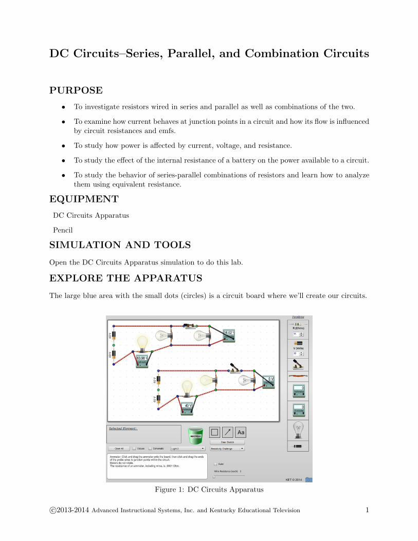
The large blue area with the small dots (circles) is a circuit board where we’ll create our circuits.
Figure 1: DC Circuits Apparatus
c©2013-2014 Advanced Instructional Systems, Inc. and Kentucky Educational Television 1
In the lab toolbox shown in Figure 1, we see our choices of resistors, batteries, switches, wires,voltmeters, ammeters, bulbs, and diodes. Each of the circuit elements can be dragged and droppedonto the circuit board. Give it a try.
1 Drag one of each type of circuit element onto the circuit board.
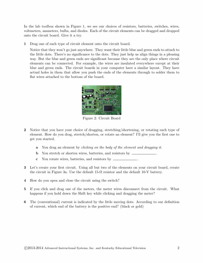
Notice that they won’t go just anywhere. They want their little blue and green ends to attach tothe little dots. There’s no significance to the dots. They just help us align things in a pleasingway. But the blue and green ends are significant because they are the only place where circuitelements can be connected. For example, the wires are insulated everywhere except at theirblue and green ends. The circuit boards in your computer have a similar layout. They haveactual holes in them that allow you push the ends of the elements through to solder them toflat wires attached to the bottom of the board.
Figure 2: Circuit Board
2 Notice that you have your choice of dragging, stretching/shortening, or rotating each type ofelement. How do you drag, stretch/shorten, or rotate an element? I’ll give you the first one toget you started.
a You drag an element by clicking on the body of the element and dragging it.
b You stretch or shorten wires, batteries, and resistors by .
c You rotate wires, batteries, and resistors by .
3 Let’s create your first circuit. Using all but two of the elements on your circuit board, createthe circuit in Figure 3a. Use the default 15-Ω resistor and the default 10-V battery.
4 How do you open and close the circuit using the switch?
5 If you click and drag one of the meters, the meter wires disconnect from the circuit. Whathappens if you hold down the Shift key while clicking and dragging the meter?
6 The (conventional) current is indicated by the little moving dots. According to our definitionof current, which end of the battery is the positive end? (black or gold)
c©2013-2014 Advanced Instructional Systems, Inc. and Kentucky Educational Television 2
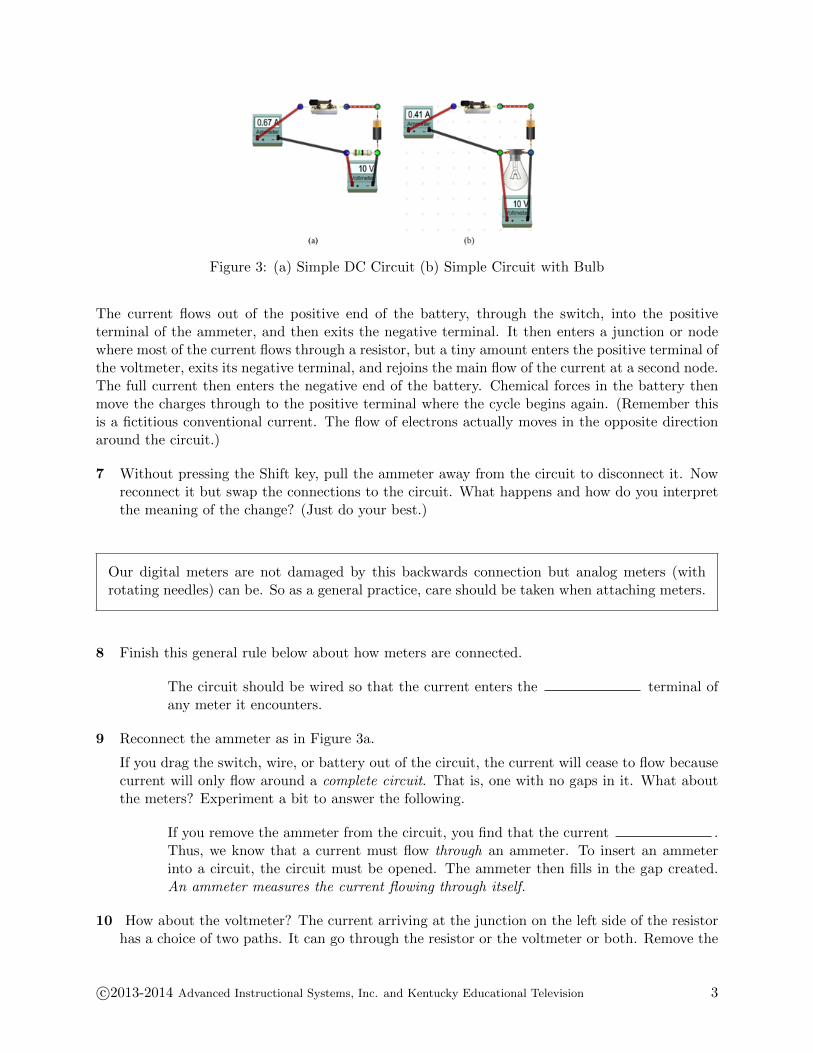
Figure 3: (a) Simple DC Circuit (b) Simple Circuit with Bulb
The current flows out of the positive end of the battery, through the switch, into the positiveterminal of the ammeter, and then exits the negative terminal. It then enters a junction or nodewhere most of the current flows through a resistor, but a tiny amount enters the positive terminal ofthe voltmeter, exits its negative terminal, and rejoins the main flow of the current at a second node.The full current then enters the negative end of the battery. Chemical forces in the battery thenmove the charges through to the positive terminal where the cycle begins again. (Remember thisis a fictitious conventional current. The flow of electrons actually moves in the opposite directionaround the circuit.)
7 Without pressing the Shift key, pull the ammeter away from the circuit to disconnect it. Nowreconnect it but swap the connections to the circuit. What happens and how do you interpretthe meaning of the change? (Just do your best.)
Our digital meters are not damaged by this backwards connection but analog meters (withrotating needles) can be. So as a general practice, care should be taken when attaching meters.
8 Finish this general rule below about how meters are connected.
The circuit should be wired so that the current enters the terminal ofany meter it encounters.
9 Reconnect the ammeter as in Figure 3a.
If you drag the switch, wire, or battery out of the circuit, the current will cease to flow becausecurrent will only flow around a complete circuit. That is, one with no gaps in it. What aboutthe meters? Experiment a bit to answer the following.
If you remove the ammeter from the circuit, you find that the current .Thus, we know that a current must flow through an ammeter. To insert an ammeterinto a circuit, the circuit must be opened. The ammeter then fills in the gap created.An ammeter measures the current flowing through itself.
10 How about the voltmeter? The current arriving at the junction on the left side of the resistorhas a choice of two paths. It can go through the resistor or the voltmeter or both. Remove the
c©2013-2014 Advanced Instructional Systems, Inc. and Kentucky Educational Television 3

resistor first, then replace it and remove the voltmeter. Look carefully at the current dots andthe ammeter each time.
A voltmeter is connected across a circuit element. That is, it’s attached to each endof the circuit element. Most of the current flows through the with anegligible amount going through the . The smaller the proportion ofthe current that flows through it, the better the voltmeter.
The meters record currents and voltage drops in the circuit. When you add them to a circuit, thisactually makes a small change in the currents and voltages you’re interested in measuring. Thisis the case with any measurement. When you put a cool thermometer into a beaker of hot water,heat flows from the water into the thermometer, thus changing the water’s temperature. A goodmeasuring tool reduces these influences as much as possible.
11 Circuit elements are inserted into a circuit to produce certain desired results. Let’s see howthat works. First, let’s record some initial values. Record the initial current and the voltagedrop.
12 Now let’s replace the resistor with an upside down bulb. Just drag the resistor off to the side.Make room for the bulb by Shift+dragging the voltmeter down a little. Now bring on a bulb,rotate it 180, and put it where the resistor was. Record your new meter readings with thebulb.
13 That’s not much light. Or is it glowing at all? To test, drag the battery away from its contactsand then bring it back. You should see the small change in brightness. We need a “bigger”battery. Click on the battery in the circuit. Below the circuit board, you’ll see a text boxshowing that the battery voltage is 10 V. There is a numeric stepper beside it that you canuse to adjust the voltage up to a maximum of 60 V. (Variable voltage batteries don’t reallyexist.) You can also just type in a number, but use the stepper to gradually increase the batteryvoltage up to 60 V. Just hold down the up arrow and notice the change in brightness (power).
NOTE:
If you set a resistance or voltage value by typing in a number, you must then hit Enter to setthe new value.
Record your new meter readings with the 60-V battery.
14 OK, that looks better. This bulb seems to be designed for 60 volts. But suppose we’d like todim it for a romantic dinner. We could switch batteries again, but that would be a nuisance.Let’s add a variable resistor. (Actually, all our resistors are variable. And variable resistorsdo exist. You own a lot of them.) Remove the short wire at the top, beside the switch, andreplace it with a resistor. Click on the resistor and then increase its resistance using the numericstepper below the circuit board. You should see the bulb dim.
15 So what’s with the numeric steppers in the Toolbox and below the circuit board? The ones inthe toolbox preset the voltage or resistance of a battery or resistor that you then want to drag
c©2013-2014 Advanced Instructional Systems, Inc. and Kentucky Educational Television 4
onto the circuit board. The ones below the circuit board change these values for a battery orresistor that you select on the circuit board by clicking on it. The ones in the toolbox set thevalues for a battery or resistor that you will then drag onto the circuit board.
Series and Parallel Circuits
Consider the “life” of an electron in your car’s electrical system. Each time it leaves the negativepole of your car battery, it has a bewildering variety of routes to choose from. Just in yourradio alone, there are many routes it might take before it returns to the battery. This complexarrangement allows each component of the electrical system to get just the current it needs. Theanalysis of such complex systems is beyond the scope of an introductory physics class, but manyof the principles involved can be discovered using simple batteries, resistors, bulbs, and meters. Byobserving the brightness (Power = IV ) of a simple bulb, we can learn how current and power aredistributed in a complex circuit.
The first part of this lab is an exploration. Your goal is to observe and organize your observationsinto models of the behavior of simple circuits. If you’re working with a team, be sure to take turnsdoing the wiring. Feel free to go off the path. When you do, just be careful to avoid situationswhere current can flow through a path with little resistance, that is, one where there is no lightbulb. Also, save your batteries by opening the circuit whenever you don’t really need to see thebulbs glow.
Well, not really. This is a virtual apparatus. You can’t hurt it. But in a real circuit, shorting outa battery means you’ll have to buy a new real one.
PROCEDURE
Please print the worksheet for this lab. You will need this sheet to record your data.
I. Explore Series, Parallel Circuits, and Combination Circuits
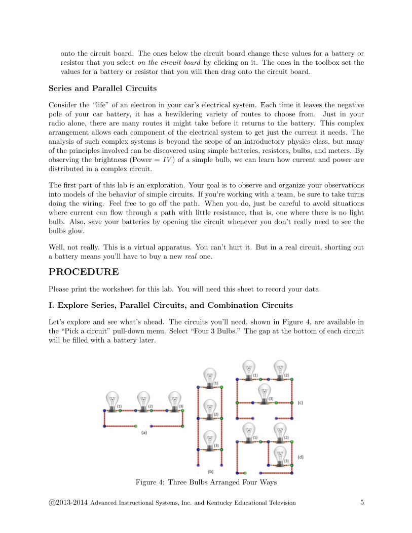
Let’s explore and see what’s ahead. The circuits you’ll need, shown in Figure 4, are available inthe “Pick a circuit” pull-down menu. Select “Four 3 Bulbs.” The gap at the bottom of each circuitwill be filled with a battery later.
Figure 4: Three Bulbs Arranged Four Ways
c©2013-2014 Advanced Instructional Systems, Inc. and Kentucky Educational Television 5
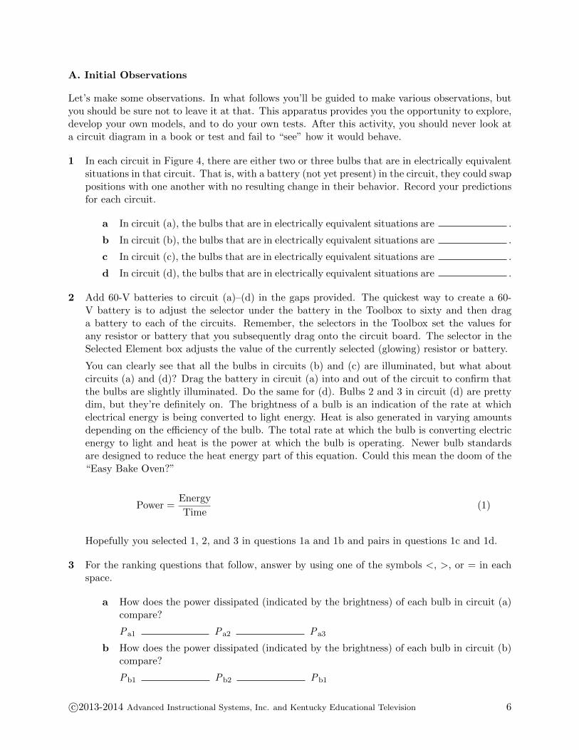
A. Initial Observations
Let’s make some observations. In what follows you’ll be guided to make various observations, butyou should be sure not to leave it at that. This apparatus provides you the opportunity to explore,develop your own models, and to do your own tests. After this activity, you should never look ata circuit diagram in a book or test and fail to “see” how it would behave.
1 In each circuit in Figure 4, there are either two or three bulbs that are in electrically equivalentsituations in that circuit. That is, with a battery (not yet present) in the circuit, they could swappositions with one another with no resulting change in their behavior. Record your predictionsfor each circuit.
a In circuit (a), the bulbs that are in electrically equivalent situations are .
b In circuit (b), the bulbs that are in electrically equivalent situations are .
c In circuit (c), the bulbs that are in electrically equivalent situations are .
d In circuit (d), the bulbs that are in electrically equivalent situations are .
2 Add 60-V batteries to circuit (a)–(d) in the gaps provided. The quickest way to create a 60-V battery is to adjust the selector under the battery in the Toolbox to sixty and then draga battery to each of the circuits. Remember, the selectors in the Toolbox set the values forany resistor or battery that you subsequently drag onto the circuit board. The selector in theSelected Element box adjusts the value of the currently selected (glowing) resistor or battery.
You can clearly see that all the bulbs in circuits (b) and (c) are illuminated, but what aboutcircuits (a) and (d)? Drag the battery in circuit (a) into and out of the circuit to confirm thatthe bulbs are slightly illuminated. Do the same for (d). Bulbs 2 and 3 in circuit (d) are prettydim, but they’re definitely on. The brightness of a bulb is an indication of the rate at whichelectrical energy is being converted to light energy. Heat is also generated in varying amountsdepending on the efficiency of the bulb. The total rate at which the bulb is converting electricenergy to light and heat is the power at which the bulb is operating. Newer bulb standardsare designed to reduce the heat energy part of this equation. Could this mean the doom of the“Easy Bake Oven?”
Power =Energy
Time(1)
Hopefully you selected 1, 2, and 3 in questions 1a and 1b and pairs in questions 1c and 1d.
3 For the ranking questions that follow, answer by using one of the symbols <, >, or = in eachspace.
a How does the power dissipated (indicated by the brightness) of each bulb in circuit (a)compare?
Pa1 Pa2 Pa3
b How does the power dissipated (indicated by the brightness) of each bulb in circuit (b)compare?
Pb1 Pb2 Pb1
c©2013-2014 Advanced Instructional Systems, Inc. and Kentucky Educational Television 6
c How does the power dissipated (indicated by the brightness) of each bulb in circuit (c)compare?
Pc1 Pc2 Pc3
d How does the power dissipated (indicated by the brightness) of each bulb in circuit (d)compare?
Pd1 Pd2 Pd3
We can calculate the power dissipated in terms of the current through a bulb, I, the resistance of abulb, R, and potential difference across a bulb, V.
P = IV = I2R =V 2
R(2)
From the similarities and differences in the brightnesses of the bulbs, it would appear that theremust be significant differences in the currents and voltages in these circuits. Since all four circuitsare made of identical components, it appears that their arrangement is key to their electricalbehavior.
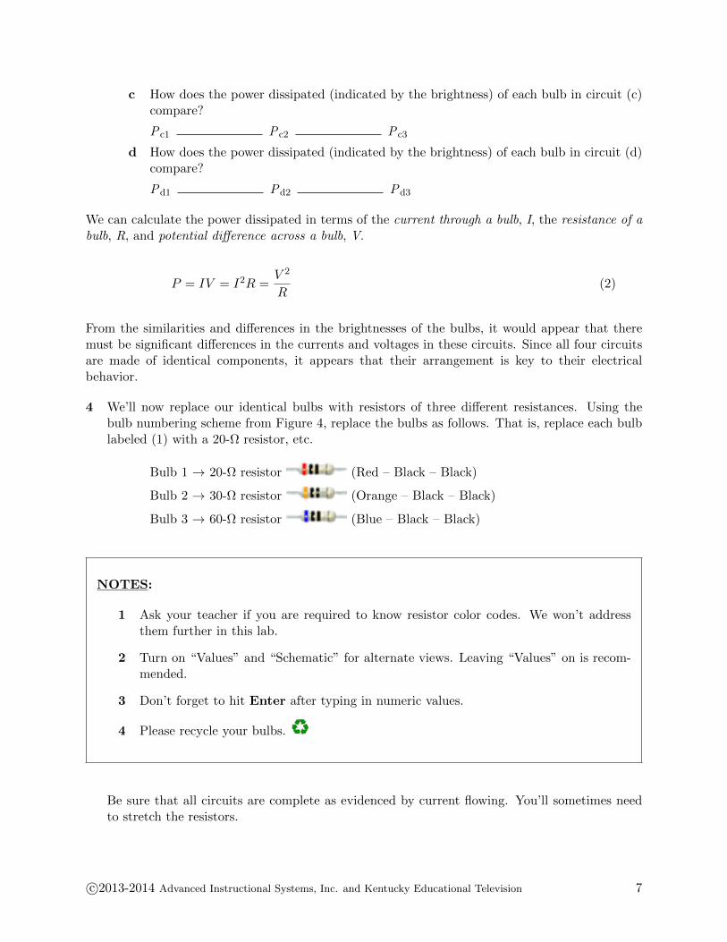
4 We’ll now replace our identical bulbs with resistors of three different resistances. Using thebulb numbering scheme from Figure 4, replace the bulbs as follows. That is, replace each bulblabeled (1) with a 20-Ω resistor, etc.
Bulb 1 → 20-Ω resistor (Red – Black – Black)
Bulb 2 → 30-Ω resistor (Orange – Black – Black)
Bulb 3 → 60-Ω resistor (Blue – Black – Black)
NOTES:
1 Ask your teacher if you are required to know resistor color codes. We won’t addressthem further in this lab.
2 Turn on “Values” and “Schematic” for alternate views. Leaving “Values” on is recom-mended.
3 Don’t forget to hit Enter after typing in numeric values.
4 Please recycle your bulbs.
Be sure that all circuits are complete as evidenced by current flowing. You’ll sometimes needto stretch the resistors.
c©2013-2014 Advanced Instructional Systems, Inc. and Kentucky Educational Television 7
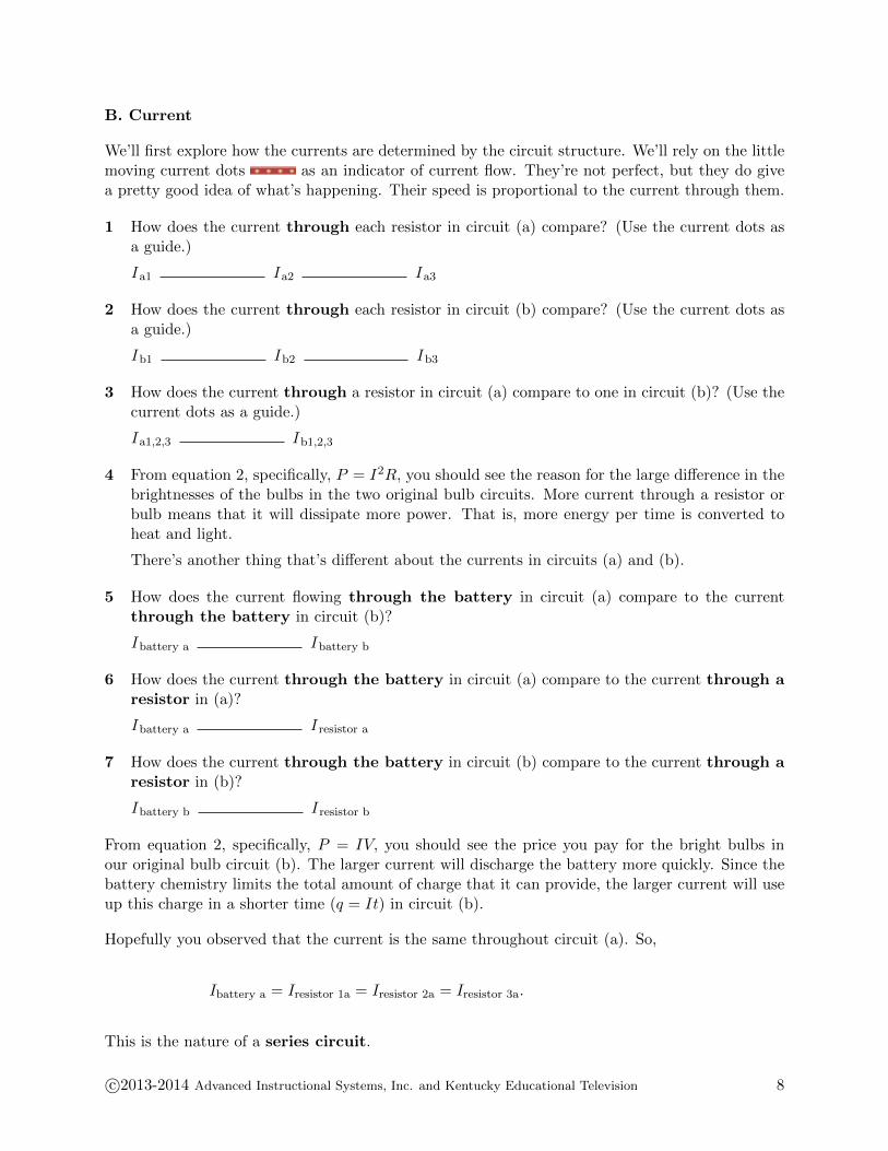
B. Current
We’ll first explore how the currents are determined by the circuit structure. We’ll rely on the littlemoving current dots as an indicator of current flow. They’re not perfect, but they do givea pretty good idea of what’s happening. Their speed is proportional to the current through them.
1 How does the current through each resistor in circuit (a) compare? (Use the current dots asa guide.)
I a1 I a2 I a3
2 How does the current through each resistor in circuit (b) compare? (Use the current dots asa guide.)
I b1 I b2 I b3
3 How does the current through a resistor in circuit (a) compare to one in circuit (b)? (Use thecurrent dots as a guide.)
I a1,2,3 I b1,2,3
4 From equation 2, specifically, P = I2R, you should see the reason for the large difference in thebrightnesses of the bulbs in the two original bulb circuits. More current through a resistor orbulb means that it will dissipate more power. That is, more energy per time is converted toheat and light.
There’s another thing that’s different about the currents in circuits (a) and (b).
5 How does the current flowing through the battery in circuit (a) compare to the currentthrough the battery in circuit (b)?
I battery a I battery b
6 How does the current through the battery in circuit (a) compare to the current through aresistor in (a)?
I battery a I resistor a
7 How does the current through the battery in circuit (b) compare to the current through aresistor in (b)?
I battery b I resistor b
From equation 2, specifically, P = IV, you should see the price you pay for the bright bulbs inour original bulb circuit (b). The larger current will discharge the battery more quickly. Since thebattery chemistry limits the total amount of charge that it can provide, the larger current will useup this charge in a shorter time (q = It) in circuit (b).
Hopefully you observed that the current is the same throughout circuit (a). So,
Ibattery a = Iresistor 1a = Iresistor 2a = Iresistor 3a.
This is the nature of a series circuit.
c©2013-2014 Advanced Instructional Systems, Inc. and Kentucky Educational Television 8

When circuit elements between two points are connected end to end with no branching, as incircuit (a), the current through each element is the same. This is called a series circuit.
8 Something entirely different is happening in circuit (b). Notice the current flowing up the leftside of the circuit. Using our ranking system, we might say
I battery I bottom left wire I middle left wire I top left wire.
9 So a relatively large current flows through the battery and part of it branches off to pass througheach bulb. Let’s improve on our simple “follow the current dots” estimation of the current byadding some meters and take some actual data for both circuits.
Edit circuit (a) to add three ammeters and a switch as shown in Figure 5. You may want touse the check boxes to turn on the “Values” of the resistors and batteries. Also, “Schematic”mode will help get you accustomed to circuit diagrams. But the pictorial view is a bit nicer tolook at.
Figure 5: Current in Series
By the way, please try not to get attached to the meters. Their little flailing arms are right upthere with cat videos but don’t let them entice you to hook them up to every little node theypass. If you find yourself using terms like “adorable” just drag a few of them straight to thetrash to desensitize yourself.
10 Close the switch and record the currents.
While the ammeters are not directly measuring the current within the resistors, if the currentflowing into one end of a resistor is the same as the current flowing out the other end it wouldbe hard to explain how the current, the number charges per second, could be different within theresistor. Otherwise the law of conservation of charge would be violated. So the statement aboutthe nature of the series circuit above seems to hold true for this series circuit.
11 Making similar measurements in our parallel circuit (b) requires a bit more reorganization.Let’s measure the current leaving the battery as well as the current through each bulb. We’lldo this by dragging all three vertical wires on the left by two grid spaces to the left, and theninsert ammeters in the gaps. We’ll also replace the bottom right wire with an open switch.
c©2013-2014 Advanced Instructional Systems, Inc. and Kentucky Educational Television 9
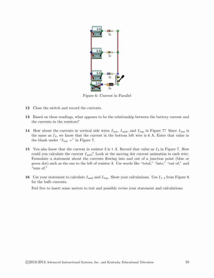
Figure 6: Current in Parallel
12 Close the switch and record the currents.
13 Based on these readings, what appears to be the relationship between the battery current andthe currents in the resistors?
14 How about the currents in vertical side wires I bot, I mid, and I top in Figure 7? Since I bot isthe same as I 4, we know that the current in the bottom left wire is 6 A. Enter that value inthe blank under “I bot =” in Figure 7.
15 You also know that the current in resistor 3 is 1 A. Record that value as I 3 in Figure 7. Howcould you calculate the current I mid? Look at the moving dot current animation in each wire.Formulate a statement about the currents flowing into and out of a junction point (blue orgreen dot) such as the one to the left of resistor 3. Use words like “total,” “into,” “out of,” and“sum of.”
16 Use your statement to calculate I mid and I top. Show your calculations. Use I 1–4 from Figure 6for the bulb currents.
Feel free to insert some meters to test and possibly revise your statement and calculations.
c©2013-2014 Advanced Instructional Systems, Inc. and Kentucky Educational Television 10

Figure 7: Current Readings
So the fundamental statement about the current in a circuit like (b) is
Ibattery b = I1 + I2 + I3.
This is the nature of a parallel circuit.
When multiple paths exist between two points in a circuit, as in circuit (b), the current dividesat the first point and then recombines at the later point. This is called a parallel circuit.The current at the entering and exit points equals the sum of the currents in the branches.
You now know equations describing the current flowing in series and parallel circuits:
Is = I1 = I2 = I3 Series Current (3)
Ip = I1 + I2 + I3 Parallel Current (4)
where I s or I p is the current flowing into or out of the series or parallel section of the circuit andI 1–3 are the currents in the three resistors.
You’ve also (hopefully) created Kirchhoff’s Point Rule describing the current flow at a point ina circuit.
c©2013-2014 Advanced Instructional Systems, Inc. and Kentucky Educational Television 11
KIRCHOFF’S POINT RULE:
The total current flowing into a point equals the total current flowing out of the point.
or
ΣI point = 0 where currents in are positive and currents out are negative.
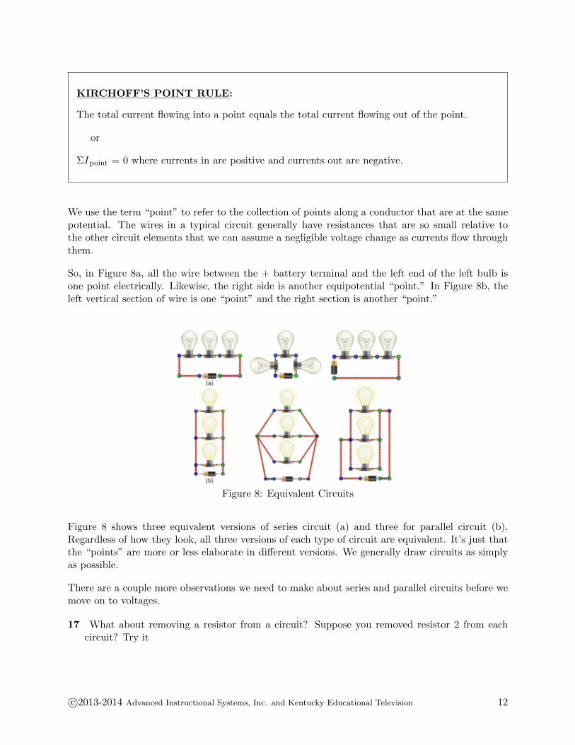
We use the term “point” to refer to the collection of points along a conductor that are at the samepotential. The wires in a typical circuit generally have resistances that are so small relative tothe other circuit elements that we can assume a negligible voltage change as currents flow throughthem.
So, in Figure 8a, all the wire between the + battery terminal and the left end of the left bulb isone point electrically. Likewise, the right side is another equipotential “point.” In Figure 8b, theleft vertical section of wire is one “point” and the right section is another “point.”
Figure 8: Equivalent Circuits
Figure 8 shows three equivalent versions of series circuit (a) and three for parallel circuit (b).Regardless of how they look, all three versions of each type of circuit are equivalent. It’s just thatthe “points” are more or less elaborate in different versions. We generally draw circuits as simplyas possible.
There are a couple more observations we need to make about series and parallel circuits before wemove on to voltages.
17 What about removing a resistor from a circuit? Suppose you removed resistor 2 from eachcircuit? Try it
c©2013-2014 Advanced Instructional Systems, Inc. and Kentucky Educational Television 12
18 The resistors in circuit (a) are connected in series. The resistors in circuit (b) are connectedin parallel. Make a general statement about the effect of removing a bulb from each type ofcircuit. Specifically, what happens to the current through the remaining bulbs?
C. Voltage
Your results above should have confirmed that power increases with current. What about voltage?The “V ” terms in equation 2 represent the voltage drop across a bulb or voltage increase acrossa battery. So we can now relate power dissipation by our resistors to voltage just as we did withcurrent.
P = IV = I2R =V 2
R
We don’t have anything corresponding to the moving current dots to visually represent voltagechanges so we’ll need to start right away with voltmeters. Unlike ammeters, voltmeters don’trequire that you open a circuit to add them. Since they’re simpler to work with, we’ll look at bothseries and parallel circuits at the same time.
1 Starting over with the “Four 3 bulbs” circuit, rebuild the series circuit (a) and the parallelcircuit (b) by replacing bulbs 1–3 with 20 Ω, 30 Ω, and 60 Ω, as you did earlier. Be sure toleave the switches open. (You’ll have to switch to another circuit and then back to “Four 3bulbs.”)
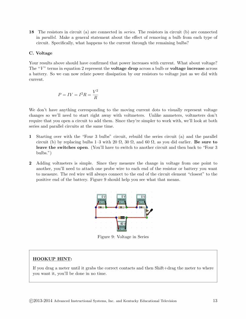
2 Adding voltmeters is simple. Since they measure the change in voltage from one point toanother, you’ll need to attach one probe wire to each end of the resistor or battery you wantto measure. The red wire will always connect to the end of the circuit element “closest” to thepositive end of the battery. Figure 9 should help you see what that means.
Figure 9: Voltage in Series
HOOKUP HINT:
If you drag a meter until it grabs the correct contacts and then Shift+drag the meter to whereyou want it, you’ll be done in no time.
c©2013-2014 Advanced Instructional Systems, Inc. and Kentucky Educational Television 13

3 In your investigation of current, you found the current to be the same everywhere in the seriescircuit. For the parallel circuit, the battery current equaled the sum of the currents in the threebranches. What similar statement do you think will apply with voltages? How do you thinkthe battery voltage will be related to the resistor voltage drops in each type of circuit? Makea statement about each type of circuit below. Use words like “total,” “across,” and “sum of.”
4 Based on your statement, make a prediction before closing the switches. Above or below eachvoltmeter in Figures 9 and 10, write the approximate voltage reading you expect to find onthat meter.
Figure 10: Voltage in Parallel
5 OK, close the switches. How’d you do?
We now have current and voltage equations for series and parallel circuits.
Series Parallel
Current I = I1 = I2 = I3 I = I1 + I2 + I3
Voltage V = V1 + V2 + V3 (5) V = V1 = V2 = V3 (6)
Notice that the equations are similar. The + and = signs are just swapped. If you look back atthe behavior of the circuits, it should be very easy to see why they behave this way. This shouldalso help you to remember these equations.
How about circuits (c) and (d)? Neither of these is simply a series or parallel circuit. Each of thesecontains a section of its circuitry that is either series or parallel.
c©2013-2014 Advanced Instructional Systems, Inc. and Kentucky Educational Television 14
6 In circuit (c), bulbs and are connected in , andthis pair is connected in with bulb .
7 In circuit (d), bulbs and are connected in ,and this pair is connected in with bulb .
D. Resistance
In both the series and parallel circuits you’ve been working with, the individual resistances andbattery voltages have been the same. But the result, the power dissipation by the individualresistors and bulbs, has been very different. Somehow the arrangement of the resistors in the twocircuits has influenced the current flowing through them and the voltage drops across them.
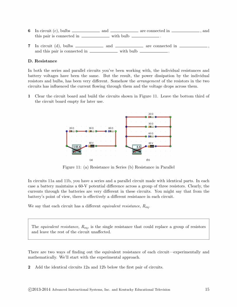
1 Clear the circuit board and build the circuits shown in Figure 11. Leave the bottom third ofthe circuit board empty for later use.
Figure 11: (a) Resistance in Series (b) Resistance in Parallel
In circuits 11a and 11b, you have a series and a parallel circuit made with identical parts. In eachcase a battery maintains a 60-V potential difference across a group of three resistors. Clearly, thecurrents through the batteries are very different in these circuits. You might say that from thebattery’s point of view, there is effectively a different resistance in each circuit.
We say that each circuit has a different equivalent resistance, Req.
The equivalent resistance, Req, is the single resistance that could replace a group of resistorsand leave the rest of the circuit unaffected.
There are two ways of finding out the equivalent resistance of each circuit—experimentally andmathematically. We’ll start with the experimental approach.
2 Add the identical circuits 12a and 12b below the first pair of circuits.
c©2013-2014 Advanced Instructional Systems, Inc. and Kentucky Educational Television 15
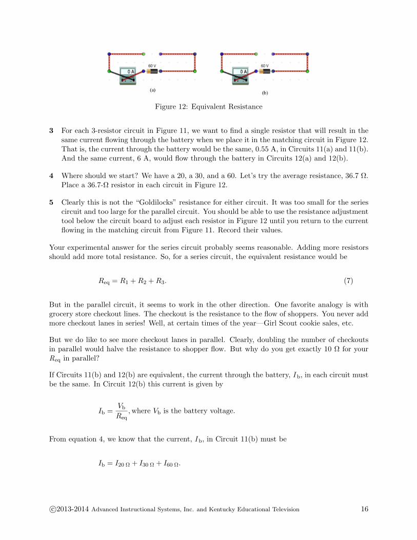
Figure 12: Equivalent Resistance
3 For each 3-resistor circuit in Figure 11, we want to find a single resistor that will result in thesame current flowing through the battery when we place it in the matching circuit in Figure 12.That is, the current through the battery would be the same, 0.55 A, in Circuits 11(a) and 11(b).And the same current, 6 A, would flow through the battery in Circuits 12(a) and 12(b).
4 Where should we start? We have a 20, a 30, and a 60. Let’s try the average resistance, 36.7 Ω.Place a 36.7-Ω resistor in each circuit in Figure 12.
5 Clearly this is not the “Goldilocks” resistance for either circuit. It was too small for the seriescircuit and too large for the parallel circuit. You should be able to use the resistance adjustmenttool below the circuit board to adjust each resistor in Figure 12 until you return to the currentflowing in the matching circuit from Figure 11. Record their values.
Your experimental answer for the series circuit probably seems reasonable. Adding more resistorsshould add more total resistance. So, for a series circuit, the equivalent resistance would be
Req = R1 + R2 + R3. (7)
But in the parallel circuit, it seems to work in the other direction. One favorite analogy is withgrocery store checkout lines. The checkout is the resistance to the flow of shoppers. You never addmore checkout lanes in series! Well, at certain times of the year—Girl Scout cookie sales, etc.
But we do like to see more checkout lanes in parallel. Clearly, doubling the number of checkoutsin parallel would halve the resistance to shopper flow. But why do you get exactly 10 Ω for yourReq in parallel?
If Circuits 11(b) and 12(b) are equivalent, the current through the battery, I b, in each circuit mustbe the same. In Circuit 12(b) this current is given by
Ib =Vb
Req,where Vb is the battery voltage.
From equation 4, we know that the current, I b, in Circuit 11(b) must be
Ib = I20 Ω + I30 Ω + I60 Ω.
c©2013-2014 Advanced Instructional Systems, Inc. and Kentucky Educational Television 16
From equation 6, we know that the voltage across each parallel resistor is V b. So from Ohm’s Law,we can write the currents in the individual branches as
I20 Ω =Vb
20 Ω, and I30 Ω =
Vb
30 Ω, and so on.
Thus, for Circuit 11(b) we have
Ib = I20 Ω + I30 Ω + I60 Ω =Vb
20 Ω+
Vb
30 Ω+
Vb
60 Ω.
Combining our equations for I b in Circuits 11(b) and 12(b), we have
Vb
Req=
Vb
20 Ω+
Vb
30 Ω+
Vb
60 Ω.
Dividing each term by V b, we have
1
Req=
1
20 Ω+
1
30 Ω+
1
60 Ω=
1
10 Ω,
so Req = 10 Ω as we found experimentally!
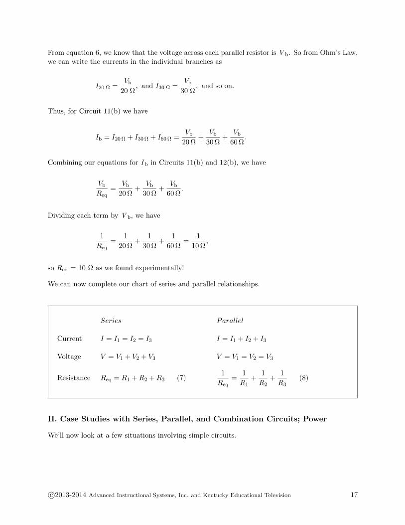
We can now complete our chart of series and parallel relationships.
Series Parallel
Current I = I1 = I2 = I3 I = I1 + I2 + I3
Voltage V = V1 + V2 + V3 V = V1 = V2 = V3
Resistance Req = R1 + R2 + R3 (7)1
Req=
1
R1+
1
R2+
1
R3(8)
II. Case Studies with Series, Parallel, and Combination Circuits; Power
We’ll now look at a few situations involving simple circuits.
c©2013-2014 Advanced Instructional Systems, Inc. and Kentucky Educational Television 17
A. Internal Resistance, Terminal Voltage, and “Dead Batteries”
Everyone is familiar with the gradual dimming of a flashlight over time. Is this some sort of designfeature to alert you when it’s time to replace the batteries, or recharge them if they’re rechargeable?
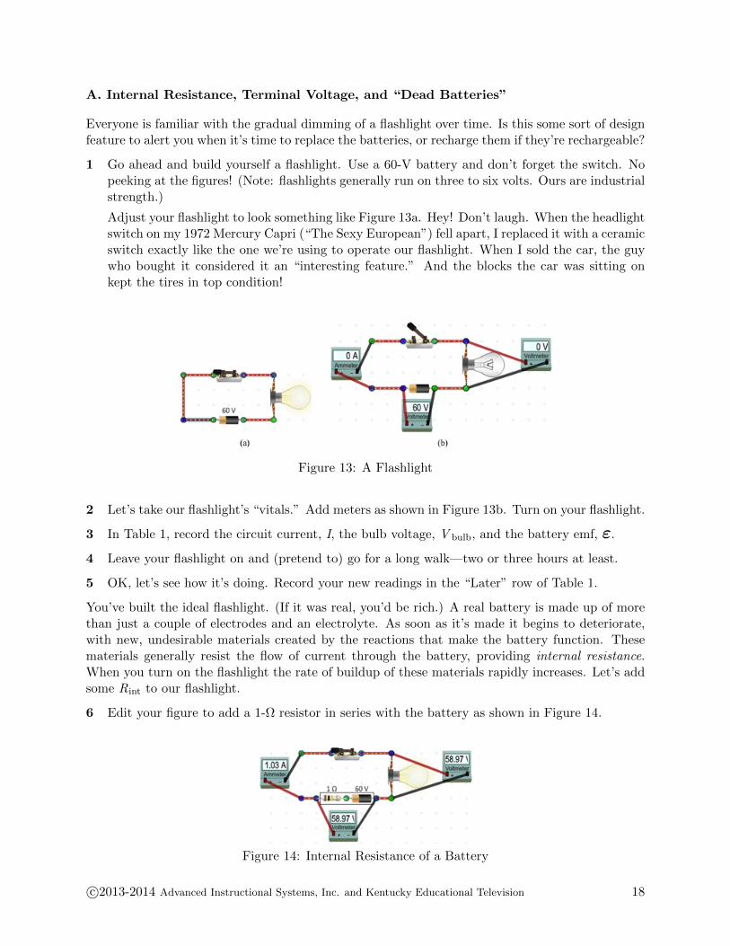
1 Go ahead and build yourself a flashlight. Use a 60-V battery and don’t forget the switch. Nopeeking at the figures! (Note: flashlights generally run on three to six volts. Ours are industrialstrength.)
Adjust your flashlight to look something like Figure 13a. Hey! Don’t laugh. When the headlightswitch on my 1972 Mercury Capri (“The Sexy European”) fell apart, I replaced it with a ceramicswitch exactly like the one we’re using to operate our flashlight. When I sold the car, the guywho bought it considered it an “interesting feature.” And the blocks the car was sitting onkept the tires in top condition!
Figure 13: A Flashlight
2 Let’s take our flashlight’s “vitals.” Add meters as shown in Figure 13b. Turn on your flashlight.
3 In Table 1, record the circuit current, I, the bulb voltage, V bulb, and the battery emf, ε.
4 Leave your flashlight on and (pretend to) go for a long walk—two or three hours at least.
5 OK, let’s see how it’s doing. Record your new readings in the “Later” row of Table 1.
You’ve built the ideal flashlight. (If it was real, you’d be rich.) A real battery is made up of morethan just a couple of electrodes and an electrolyte. As soon as it’s made it begins to deteriorate,with new, undesirable materials created by the reactions that make the battery function. Thesematerials generally resist the flow of current through the battery, providing internal resistance.When you turn on the flashlight the rate of buildup of these materials rapidly increases. Let’s addsome Rint to our flashlight.
6 Edit your figure to add a 1-Ω resistor in series with the battery as shown in Figure 14.
Figure 14: Internal Resistance of a Battery
c©2013-2014 Advanced Instructional Systems, Inc. and Kentucky Educational Television 18
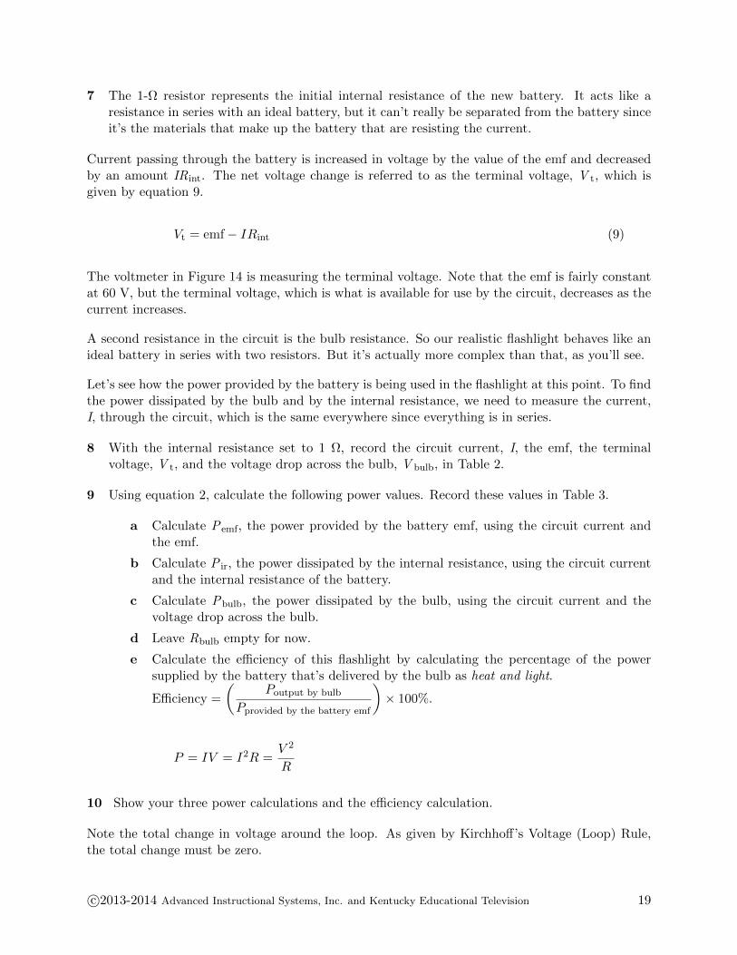
7 The 1-Ω resistor represents the initial internal resistance of the new battery. It acts like aresistance in series with an ideal battery, but it can’t really be separated from the battery sinceit’s the materials that make up the battery that are resisting the current.
Current passing through the battery is increased in voltage by the value of the emf and decreasedby an amount IRint. The net voltage change is referred to as the terminal voltage, V t, which isgiven by equation 9.
Vt = emf− IRint (9)
The voltmeter in Figure 14 is measuring the terminal voltage. Note that the emf is fairly constantat 60 V, but the terminal voltage, which is what is available for use by the circuit, decreases as thecurrent increases.
A second resistance in the circuit is the bulb resistance. So our realistic flashlight behaves like anideal battery in series with two resistors. But it’s actually more complex than that, as you’ll see.
Let’s see how the power provided by the battery is being used in the flashlight at this point. To findthe power dissipated by the bulb and by the internal resistance, we need to measure the current,I, through the circuit, which is the same everywhere since everything is in series.
8 With the internal resistance set to 1 Ω, record the circuit current, I, the emf, the terminalvoltage, V t, and the voltage drop across the bulb, V bulb, in Table 2.
9 Using equation 2, calculate the following power values. Record these values in Table 3.
a Calculate Pemf, the power provided by the battery emf, using the circuit current andthe emf.
b Calculate P ir, the power dissipated by the internal resistance, using the circuit currentand the internal resistance of the battery.
c Calculate Pbulb, the power dissipated by the bulb, using the circuit current and thevoltage drop across the bulb.
d Leave Rbulb empty for now.
e Calculate the efficiency of this flashlight by calculating the percentage of the powersupplied by the battery that’s delivered by the bulb as heat and light.
Efficiency =
(Poutput by bulb
Pprovided by the battery emf
)× 100%.
P = IV = I2R =V 2
R
10 Show your three power calculations and the efficiency calculation.
Note the total change in voltage around the loop. As given by Kirchhoff’s Voltage (Loop) Rule,the total change must be zero.
c©2013-2014 Advanced Instructional Systems, Inc. and Kentucky Educational Television 19
KIRCHOFF’S LOOP RULE:
Around any closed-circuit loop, the sum of the voltage drops equals the sum of the voltagerises.
For our circuit,
emf− Vir − Vbulb = 0 or
emf− IRir − Vbulb = 0.
60.00 V− (1.03 A)(1.00 Ω)− 58.97 V = 0.
Subtracting the battery’s internal voltage drop, V ir, reflects the internal voltage loss that’s notavailable to the external circuit that the battery is powering. It’s going to get worse!
When we turned on our ideal flashlight, we “took a walk” and found that no harm was done. Weall know that that’s not how it works. What really happens is that you can’t find your way backto the campsite, or you have to call Triple-A. Batteries have a bad habit of “running down.”
11 Leaving our real flashlight running for a while lets a lot of ugly chemistry happen in the batteryas previously discussed. The result will be an increase in the internal resistance, Rir. Changeit to 50 Ω.
12 The result is pretty obvious. Let’s check the numbers. Make the necessary readings andcalculations to fill in the 50-Ω rows in Tables 2 and 3.
13 Show your three power calculations and the efficiency calculation.
14 There’s one column in our data tables that we’ve neglected. We could have calculated thepower dissipated by the bulb using I2R as we did with the internal resistance. But we didn’tknow the resistance of the bulb. But we now know the current and voltage drop across thebulb for each internal resistance. Calculate and record Rbulb for each trial.
15 Show your bulb resistance calculations.
16 Why did the bulb resistance decrease? Do a little research and see what you can come upwith. The bulbs in this virtual apparatus are designed to behave like real bulbs. So just whatis it that’s affecting the bulb resistance?
B. Simplifying Circuits, Power Dissipation, Power Supplied by a Battery
In the circuit in figure 15, a 12-V battery supplies current to a network of four resistors. If this wasa section of a circuit in your car hooked up to your car’s 12-V battery, you might want to knowwhat size fuse should be provided to protect it from overload. Or if the 1.0-Ω resistor representeda bulb, you might want to know the proper wattage of the bulb that should be used.
c©2013-2014 Advanced Instructional Systems, Inc. and Kentucky Educational Television 20
Many students find solving this sort of problem perplexing. This is partly because it can be quitetedious and partly because without direct experience with circuits, it’s difficult to see how tovisualize a solution. We’ll now look at two different circuits. We’ll answer a few questions abouteach one, first using direct measurement from our lab simulations, and then using an algebraictechnique that requires that you reduce the circuit step by step to its simplest form and then usethese circuits to create the necessary equations to solve for unknowns.
Circuit 1
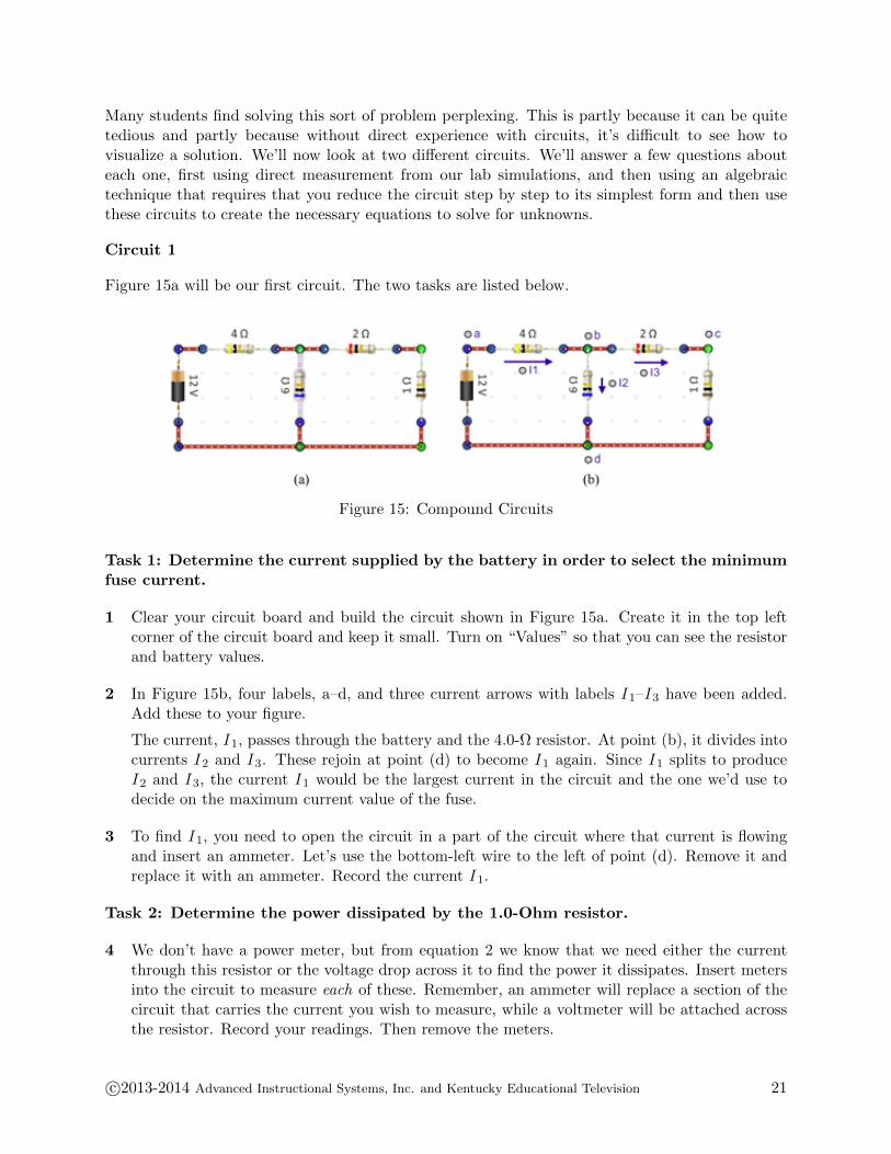
Figure 15a will be our first circuit. The two tasks are listed below.
Figure 15: Compound Circuits
Task 1: Determine the current supplied by the battery in order to select the minimumfuse current.
1 Clear your circuit board and build the circuit shown in Figure 15a. Create it in the top leftcorner of the circuit board and keep it small. Turn on “Values” so that you can see the resistorand battery values.
2 In Figure 15b, four labels, a–d, and three current arrows with labels I 1–I 3 have been added.Add these to your figure.
The current, I 1, passes through the battery and the 4.0-Ω resistor. At point (b), it divides intocurrents I 2 and I 3. These rejoin at point (d) to become I 1 again. Since I 1 splits to produceI 2 and I 3, the current I 1 would be the largest current in the circuit and the one we’d use todecide on the maximum current value of the fuse.
3 To find I 1, you need to open the circuit in a part of the circuit where that current is flowingand insert an ammeter. Let’s use the bottom-left wire to the left of point (d). Remove it andreplace it with an ammeter. Record the current I 1.
Task 2: Determine the power dissipated by the 1.0-Ohm resistor.
4 We don’t have a power meter, but from equation 2 we know that we need either the currentthrough this resistor or the voltage drop across it to find the power it dissipates. Insert metersinto the circuit to measure each of these. Remember, an ammeter will replace a section of thecircuit that carries the current you wish to measure, while a voltmeter will be attached acrossthe resistor. Record your readings. Then remove the meters.
c©2013-2014 Advanced Instructional Systems, Inc. and Kentucky Educational Television 21
5 Also calculate and record the power dissipated by the 1.0-Ω resistor.
6 There are three ways to calculate P1.0 Ω. Show all three calculations.
That was pretty simple, but we had to create a prototype in the lab and that’s a bit inconvenient.How could we make the same determinations just from the circuit diagram given that none ofthe values used above are readily available in the circuit diagram? In some simple cases, thenecessary values can be determined by reducing the circuit step-by-step and drawingsuccessively simpler equivalent circuits. We do this by finding groups of resistors that areeither in series or parallel and creating a new diagram with these groups replaced by their equivalentresistances. This is repeated until no further simplification is possible. It is essential that each ofthe diagrams is fully labeled.
Many students find this process puzzling, given that the ultimate use of this collection of circuitsis unclear. You can think of it as a process similar to writing down what you know and want toknow before beginning to think about how to solve a homework problem. What you’re doing isclarifying what you know at the start. Often, after writing down what you initially know, you cansee that there are other quantities you can readily find from these initial values. The drawing ofequivalent circuits is a similar technique. Let’s try it.
But first, let’s recall what we mean by the term point in an electric circuit. We use the term “point”to refer to the collection of points along a conductor that are at the same potential. In Figure 15,everything beneath the lower ends of the battery and two resistors is a “point.” This is because weassume that our wires have negligible resistance, so there would be no voltage changes as currentflows from one point to another in this section of the circuit.
We’re interested in replacing groups of resistors that are either in series or parallel. Let’s firstremind ourselves of the meanings of these two terms.
Two or more resistors between points (a) and (b) are in series if they are connected end to endwith no branching along the way so that the current flows through each resistor in succession. Thecurrent is the same through each resistor, but the voltage drop across each depends on the current.
Iseries = I1 = I2 = . . .
Vab = IsR1 + IsR2 + . . .
Two or more resistors between points (a) and (b) are in parallel if they are connected to commonend points (a) and (b) with each branch carrying a current that depends on its resistance. Thetotal current between (a) and (b) equals the sum of the currents through all the branches.
Iparallel = I1 + I2 + . . .
Vab = I1R1 = I2R2 = . . .
c©2013-2014 Advanced Instructional Systems, Inc. and Kentucky Educational Television 22

NOTE:
Figures 16–19 are used repeatedly in the discussion over the next several pages. To prevent theneed for flipping back and forth to see the figures, they are also provided on a single page. Youmight want to use that copy when asked to add annotations to the figures.
Geometrically, we might say that the 6.0-Ω and 1.0-Ω resistors are in parallel. However, while theydo have one common end point, (d), on the other end they are connected to points (b) and (c)which are at opposite ends of the 2.0-Ω resistor. If the 6.0-Ω and 1.0-Ω resistors are in parallel, thepotential difference across each, V bd and V cd, should be the same. Let’s measure these voltagesand see.
Figure 16: (same as 15(b))
7 Attach the negative lead of a voltmeter to point (d). Then attach the positive end to point (b)and record the voltage reading, V bd. Then move the positive lead to point (c) and record thevoltage reading, V cd. Remove the meters.
The potential difference between (b) and (d) is not the same as between (c) and (d), so the 6.0-Ωand 1.0-Ω resistors are not in parallel. You would never actually have to make a measurement likethis since points (b) and (c) would not be at the same potential if there was any kind of circuitelement such as a battery or resistor between them.
Similarly, the 4.0-Ω and 2.0-Ω resistors, while connected-to-end, are not in series because there isa branch between them at (b). So be careful in determining when resistors are in series or parallel.Notice how helpful it is to add these labeled nodes a–d. It’s a good habit to develop.
The 2.0-Ω and 1.0-Ω resistors in Figure 16 do meet our definition of series resistors; thus, we canuse equation 7 to determine their equivalent resistance and draw a new circuit with just the one3.0-Ω equivalent resistor. This resistor could be anywhere within the right section of the circuit.Be sure to include all labels and current arrows just as in the figure.
c©2013-2014 Advanced Instructional Systems, Inc. and Kentucky Educational Television 23

Figure 17
In our new Figure 17, we can see another pair of resistors that can be reduced to one resistance.The 3.0-Ω and 6.0-Ω resistors have common end points at (b) and (d). Thus, they are in parallel.
Note that all the points from the right end of the 3-Ω resistor down and around to the negativeterminal of the battery are all at the same potential. They might all be represented by point (d).
Wouldn’t the 4.0-Ω and 6.0-Ω resistors be in parallel between points (b) and (d) too? No! Thebattery is in one of these branches. We must have only resistors in the parallel or series circuitsthat we want to simplify.
We can create a new circuit in Figure 18 with one 2.0-Ω resistor between points (b) and (d) thatis equivalent to the parallel 3-Ω and 6-Ω resistors. The 2.0-Ω value of that resistor is given byequation 8.
Figure 18
Finally, we can see that the 4.0-Ω and 2.0-Ω resistors in Figure 18 are in series between points (a)and (d). Their equivalent resistance is 6.0 Ω. This gives us our final equivalent circuit.
Figure 19
c©2013-2014 Advanced Instructional Systems, Inc. and Kentucky Educational Television 24

Err. That was interesting but what were we doing? We were looking for a way to
• determine the current supplied by the battery in order to select the proper fuse.
• determine the power dissipated by the 1.0-Ohm resistor, P1.0 Ω.
And we want to do this without having access to the actual circuit. That is, we’ll have to derivethe data we need from the four circuit diagrams we’ve created.
8 First, we want to determine the current supplied by the battery in order to select an appropriatefuse to protect the circuit.
We’ve called that current I 1. I 1 appears in all four circuits. The simplest place to find it wouldbe Figure 19. The battery produces a potential difference V ad between points (a) and (d).From Figure 19, we know that the resistance between those two points is just 6.0 Ω. So withOhm’s Law, we can calculate the current I 1.
Vad = I1 × 6.0 Ω
I1 =Vad
6.0 Ω=
12 V
6.0 Ω
I1 = 2.0 A
This is the same as the result we found experimentally. Now you can see why we’ve createdthese circuits. I 1 can’t be found from the original circuit.
Write “= 2.0 A” beside each “I 1” in the four figures on your printed copy of the lab.
9 Now we want to determine the power dissipated by the 1.0-Ω resistor, P1.0 Ω.
• To do that, we probably need to find either the current through it or the voltage dropacross it. Let’s do both. Look at the four circuit diagrams.
• What’s the simplest diagram that includes the 1.0-Ω resistor?
• What labels would you give to the current through and voltage drop across this resistor?
We’re looking for I 3 and V cd. This is where it gets interesting. We now have to go hunting fora solution.
Add “= ?” beside each “I 3” and “V cd = ?” beside the 1-Ω resistor everywhere it appears onthese pages.
From the first question, we know that
I1 = 2.0 A.
How could we use this to find I 3?
c©2013-2014 Advanced Instructional Systems, Inc. and Kentucky Educational Television 25

At point b, the current I 1 splits into two currents, so, using Kirchhoff’s Point Rule, we knowthat
I1 = I2 + I3,
so I 3 = I 1 − I 2. Can we find I 2?
I 2 is the current through the 6.0-Ω resistor and the voltage drop across it is V bd. How couldwe find V bd?
In Figure 18, I 1 is the current flowing through the 2.0-Ω resistor between points (b) and (d).So we can use Ohm’s Law to calculate the voltage V bd.
Vbd = I1 × 2.0 Ω = 2.0 A× 2.0 Ω = 4.0 V
Add that to your figures.
Going back to Figure 17, we can now find I 2.
I2 =Vbd
6.0 Ω=
4.0 V
6.0 Ω
I2 = 0.67 A
Add that to your figures.
We can now find I 3.
I3 = I1 − I2 = 2.0 A− 0.67 A
I3 = 1.33 A
So,
P1.0 Ω = I23 × 1.0 Ω
P1.0 Ω = (1.33 A)2 × 1.0 Ω
P1.0 Ω = 1.8 W
which was our experimental result.
We also wanted to find P1.0 Ω from the voltage across that resistor. From Figure 16, we’d callthat V cd.
This is just the voltage drop across the 1.0-Ω resistor. Since we know the current through it,I 3, we can calculate the voltage drop across it, V cd.
c©2013-2014 Advanced Instructional Systems, Inc. and Kentucky Educational Television 26

Vcd = I3 × 1.0 Ω = 1.33 A× 1.0 ΩVcd = 1.33 V, so
P1.0 Ω =Vcd
2
1.0 Ω=
(1.33 V)2
1.0 ΩP1.0 Ω = 1.8 W
which was again our experimental result.
Whew! That was a lot of work. Hopefully you’re now a believer in carefully documenting whatyou know and want to know.
Circuit 2
It’s your turn now. You’ll work with the circuit below in Figure 20.
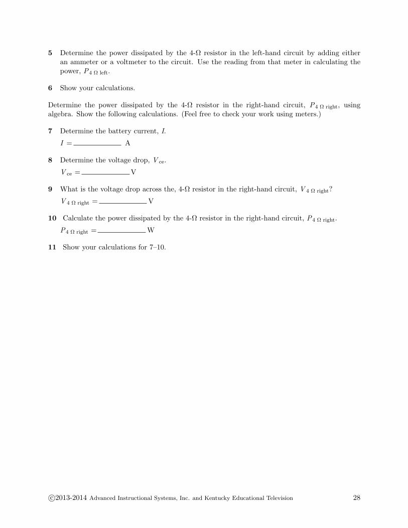
Your task is to determine the power dissipated by each of the two 4-Ω resistors. You’ll find thepower dissipated by the left one, P4 Ω left, by measurements taken from the apparatus. You’ll findP4 Ω right using algebra.
Figure 20
1 Near the top left corner of the circuit board, construct the circuit shown in Figure 20. Includethe five labels a–e.
2 Add and label current arrows for the battery current (labeled I ) and for each of the four parallelbranches.
Label the two currents on the left I 1 (top) and I 2 (bottom). Similarly label the two on theright I 3, and I 4. Add arrows to indicate the direction of each current.
On the circuit board add three more circuits to reduce the circuit in stages described below.Include any of the circuit labels (a–e) that exist in the successive circuits. (All except (a) and(e) will eventually disappear.) Also include any previously named currents that remain.
a Simplify each of the two series sections into single resistors to create Circuit 20b.
b Simplify each of the two resulting parallel sections into single resistors to create Circuit 20c.
c Simplify the remaining two resistors into a single resistor to create Circuit 20d.
4 Take a Screenshot of the full circuit board showing all four circuits and upload it as“DC Circuit 2.png”.
c©2013-2014 Advanced Instructional Systems, Inc. and Kentucky Educational Television 27
5 Determine the power dissipated by the 4-Ω resistor in the left-hand circuit by adding eitheran ammeter or a voltmeter to the circuit. Use the reading from that meter in calculating thepower, P4 Ω left.
6 Show your calculations.
Determine the power dissipated by the 4-Ω resistor in the right-hand circuit, P4 Ω right, usingalgebra. Show the following calculations. (Feel free to check your work using meters.)
7 Determine the battery current, I.
I = A
8 Determine the voltage drop, V ce.
V ce = V
9 What is the voltage drop across the, 4-Ω resistor in the right-hand circuit, V 4 Ω right?
V 4 Ω right = V
10 Calculate the power dissipated by the 4-Ω resistor in the right-hand circuit, P4 Ω right.
P4 Ω right = W
11 Show your calculations for 7–10.
c©2013-2014 Advanced Instructional Systems, Inc. and Kentucky Educational Television 28