day one: juniper ambassadors’ cookbook for 2014 · the juniper ambassadors reveal their best tips...
TRANSCRIPT

Junos® Networking Technologies
The Juniper Ambassadors reveal
their best tips learned over the past
year so you can bring a new level of
intelligence to your network.
By Martin Brown, Petr Klemaj, Steve Puluka, Clay Haynes, Kevin Barker,
Darren O’Connor, David Roy, & Scott Ware
DAY ONE: JUNIPER AMBASSADORS’ COOKBOOK FOR 2014
Juniper Networks Books are singularly focused on network productivity and efficiency. Peruse the complete library at www.juniper.net/books.
Published by Juniper Networks Books
DAY ONE: JUNIPER AMBASSADORS’ COOKBOOK FOR 2014
The Juniper Ambassador program recognizes and supports its top community members and the generous contributions they make through sharing their knowledge, passion, and expertise on J-Net, Facebook, Twitter, and other social networks. The Juniper Ambassa-dors are a diverse set of network engineers, consultants, and architects who work in the field with Juniper technologies on a daily basis.
This second cookbook from the Ambassadors contains eighteen use-case solutions, complete with configurations. From interop tips in mixed-vendor networks, to optimizing network routing, switching, and security performance, you’ll find this cookbook useful in the lab as well as in full-production networks.
IT’S DAY ONE AND YOU HAVE A JOB TO DO, SO LEARN HOW TO:
��Configure a Q-in-Q tunnel on the EX Series
��Use Junos configuration groups to automate network schedules and updates
��Deploy firewall policies on multiple devices with Juniper Space Security Director
��Update your QFX Series version of Spanning Tree Protocol (STP) from RSTP (802.1w) to MSTP (802.1s)
��Create independent Micro BFD sessions for LAG
��Interop the SRX Series to a variety of vendor devices
��Configure a SRX Series integrated firewall
... and eleven more from the Juniper Ambassador playlist, from MX Series port mirroring to SRX conditional route advertising.
ISBN 978-1936779987
9 781936 779987
5 1 8 0 0

By Martin Brown, Petr Klemaj, Steve Puluka, Clay Haynes, Kevin Barker, Darren O’Connor, David Roy, and Scott Ware
Day One: Juniper Ambassadors’ Cookbook 2014
Recipe 1: Configuring Q-in-Q Tunnels on the EX Series . . . . . . . . . . . . . . . . . . . . . . . . . . . . . .9
Recipe 2: Managed Switching for a Small Office Network . . . . . . . . . . . . . . . . . . . . . . . . . . 13
Recipe 3: Configuring a SRX Series Integrated Firewall . . . . . . . . . . . . . . . . . . . . . . . . . . . . .25
Recipe 4: Deploying Firewall Policies on Multiple Devices with Junos Space
Security Director . . . . . . . . . . . . . . . . . . . . . . . . . . . . . . . . . . . . . . . . . . . . . . . . . . . . . . . 29
Recipe 5: Deploying NAT Policies with Junos Space Security Director . . . . . . . . . . . . . . 39
Recipe 6: Conditional Route Advertising with NAT on the SRX Series . . . . . . . . . . . . . . 45
Recipe 7: Basic IS-IS Implementation . . . . . . . . . . . . . . . . . . . . . . . . . . . . . . . . . . . . . . . . . . . . . 53
Recipe 8: Redistributing RIP into IS-IS . . . . . . . . . . . . . . . . . . . . . . . . . . . . . . . . . . . . . . . . . . . . 59
Recipe 9: Configuring Active/Active MC-LAG on MX Series . . . . . . . . . . . . . . . . . . . . . . . . .67
Recipe 10: SRX Series OSPF Interop VPN with Palo Alto Networks . . . . . . . . . . . . . . . . . . 77
Recipe 11: SRX Series Interop VPN with Sonicwall . . . . . . . . . . . . . . . . . . . . . . . . . . . . . . . . . 89
Recipe 12: SRX Series Interop OSPF VPN with SSG . . . . . . . . . . . . . . . . . . . . . . . . . . . . . . . . .97
Recipe 13: Port Mirroring . . . . . . . . . . . . . . . . . . . . . . . . . . . . . . . . . . . . . . . . . . . . . . . . . . . . . . . . .103
Recipe 14: Configuring Multiple Proxy-IDs on an SRX IPsec VPN . . . . . . . . . . . . . . . . . . . 119
Recipe 15: Scheduling Configuration Changes with Apply-groups . . . . . . . . . . . . . . . . . . 123
Recipe 16: Configuring MSTP on the QFX5100 Series . . . . . . . . . . . . . . . . . . . . . . . . . . . . . 127
Recipe 17: Creating Independent Micro BFD Sessions for LAG . . . . . . . . . . . . . . . . . . . . . 131
Recipe 18: Quick Configuration of the Juniper-Kaspersky Antivirus on the SRX . . . . . . 135
© 2014 by Juniper Networks, Inc. All rights reserved. Juniper Networks, the Juniper Networks logo, Junos, NetScreen, and ScreenOS are registered trademarks of Juniper Networks, Inc. in the United States and other countries. Junose is a trademark of Juniper Networks, Inc. All other trademarks, service marks, registered trademarks, or registered service marks are the property of their respective owners. Juniper Networks assumes no responsibility for any inaccuracies in this document. Juniper Networks reserves the right to change, modify, transfer, or otherwise revise this publication without notice.
Published by Juniper Networks BooksAuthors: Martin Brown, Petr Klemaj, Steve Puluka, Clay Haynes, Kevin Barker, Darren O’Connor, David Roy, and Scott WareEditor in Chief: Patrick AmesCopyeditor and Proofer: Nancy KoerbelJ-Net Community Manager: Julie Wider
ISBN: 978-1-936779-98-7 (print)Printed in the USA by Vervante Corporation.
ISBN: 978-1-936779-99-4 (ebook)
Version History: v1, September 2014 2 3 4 5 6 7 8 9 10
This book is available in a variety of formats at: http://www.juniper.net/dayone. Send your suggestions, comments, and critiques by email to [email protected].
iv

Welcome to Day One
This book is part of a growing library of Day One books, produced and published by Juniper Networks Books.
Day One books were conceived to help you get just the information that you need on day one. The series covers Junos OS and Juniper Networks networking essentials with straightforward explanations, step-by-step instructions, and practical examples that are easy to follow.
The Day One library also includes a slightly larger and longer suite of This Week books, whose concepts and test bed examples are more similar to a week long seminar.
You can obtain either series, in multiple formats:
� Download a free PDF edition at http://www.juniper.net/dayone.
� Get the ebook edition for iPhones and iPads from the iTunes Store. Search for Juniper Networks Books.
� Get the ebook edition for any device that runs the Kindle app (Android, Kindle, iPad, PC, or Mac) by opening your device's Kindle app and going to the Kindle Store. Search for Juniper Networks Books.
� Purchase the paper edition at either Vervante Corporation (www.vervante.com) or Amazon (amazon.com) for between $12-$28, depending on page length.
� Note that Nook, iPad, and various Android apps can also view PDF files.
� If your device or ebook app uses .epub files, but isn't an Apple product, open iTunes and download the .epub file from the iTunes Store. You can now drag and drop the file out of iTunes onto your desktop and sync with your .epub device.
Welcome Ambassadors!
Juniper Ambassadors are global technical/brand advocates that actively participate across Juniper community and social programs. They are a diverse set of network engineers, consultants, and architects who work in the field with Juniper technologies on a daily basis. The Juniper Ambassadors’ mission is spreading the word about the power of Junos to the world’s networking and security engineers.
v
vi
Audience
This book is primarily intended for Enterprise network administrators and provides field-tested recipes for common network deployment scenarios, as well as brief background information needed to understand and deploy these solutions in your own environment.
What You Need to Know Before Reading
Before reading this book, you should be familiar with the basic adminis-trative functions of the Junos operating system, including the ability to work with operational commands and to read, understand, and change Junos configurations. There are several books in the Day One library on exploring and learning Junos available at www.juniper.net/dayone.
This book makes a few assumptions about you, the reader, and presumes you have a:
� Broad understanding of TCP/IP
� Basic knowledge of Ethernet switching concepts, such as bridging and Spanning Tree
� Solid understanding of IP, firewalls, routing, and switching concepts
� Familiarity with configuring a variety of network equipment
� Familiarity with common networking protocols and sessions such as IPsec, SSH, Telnet, and HTTPs
� Understanding of basic network administration tasks
About the Contributors
Martin Brown is a Network Engineer and Juniper Ambassador with knowledge that covers a broad range of network devices. Martin started his career in IT 20 years ago supporting Macintosh computers, and has since progressed to networking. He currently holds JNCIA and JNCIS-ENT and is working on JNCIP-ENT, time permitting.
� Martin’s Acknowledgments: There are two people I really would like to thank who have been a source of inspiration to me whilst writing these words: Paul Gledhill, who has proved to be an often patient and invaluable source of experience with anything related to networking this past year, and Sam Mason, who has just been a very good and understanding friend whenever I have needed one.

vii
Petr Klemaj is a Juniper Ambassador and a Juniper Networks certified instructor working at Poplar Systems, a Juniper-Authorized Education Partner in Russia. He is certified JNCIE-SEC #98, JNCIE-ENT #393, and JNCIE-SP #2253 and has several years of experience supporting Juniper equipment for many small and large Juniper customers. He teaches a variety of Juniper classes on a regular basis, beginning with introductory classes (such as JSE and IJOS) and including advanced classes (such as AJSEC and JAUT).
� Petr’s Acknowledgements: I would like to thank my family and my colleagues, Alex Tarkhov and Leo Mirenkov, for their constant support and inspiration.
Steve Puluka is a Senior Network Security Engineer with UPMC in Pittsburgh, PA. He is part of a team that manages about 400 firewalls – primarily ScreenOS and Junos, with a Palo Alto Networks presence – and two Cisco VPN router clusters. He holds a BSEET along with the professional-level certification in Junos Security, and specialist level in ScreenOS and SSL VPN. He also has certification and extensive experience in Microsoft Windows server, along with strong VMware skills starting with Version 2. He has enjoyed supporting networks for more than 20 years.
Clay Haynes is a Senior Systems Engineer working with CentraComm Communications, a Juniper Elite Partner based out of northwest Ohio. He has been working in IT for over 10 years, covering a wide range of technologies in servers as well as in networking. Clay is a recent addition to the Juniper Ambassadors team and currently holds certifi-cations across a wide range of networking platforms, including: JNCIE-SEC #69, JNCSP-SEC, JNCIP-ENT, JNCIS-SA, JNCIS-AC, JNCIA-IDP, Riverbed's RCSP-WAN, and Aruba's ACMP. Clay continues to work towards his JNCIE-ENT, as well as the JNCIS-SP path.
� Clay’s Acknowledgements: I would like to thank the Ambassador Team and Julie Wider for giving me the opportunity to join such a wonderful group. I also want thank my colleague Erin Ebert who has pushed me to exceed all expectations, and has remained a true friend throughout my professional career. Lastly, I want to thank my customers for providing me with interesting challenges every day!

viii
Kevin Barker, has over 30 years of IT experience spanning Operations, Applications, and Infrastructure. Kevin is a Co-founder and Chief Technology Officer of Independent Technology Group, a southern California based Juniper Elite partner. Kevin is a frequent contributor to the Juniper-user community forums, has achieved the title of Distin-guished Expert, J-Net Community, and is a member of the Juniper Ambassador program wherein he evangelizes on behalf of Juniper and Junos in the networking and security communities. He is also a JNCIP-SEC, JNICS-ENT, and a Juniper Certified Instructor.
Darren O’Connor is a Network Architect with broad experience in both Service Provider and Enterprise Networks. He holds a JNCIE-SP #2227 as well as Dual CCIE #38070 (R&S/SP). Darren is active both on his blog (mellowd.co.uk/ccie and twitter @mellowdrifter)
� Darren’s Acknowledgements: I would like to thank my wife for putting up with me constantly reading and learning new things. Thanks to my fellow Ambassadors and Patrick our editor for making this book possible.
David Roy has been a Technical Support Engineer for a Service Provider in France for seven years. Before that he worked for five years at a research and development department (IP / DVB satellite team). He loves networking and reverse engineering. He is also JNCIE-SP #703, JNCIE-ENT #305, and JNCIE-SEC#144 certified.
� David’s Acknowledgements: I would like to thank my colleagues who reviewed my technical recipe.
Scott Ware is a Network Security Engineer and Juniper Ambassador. He currently holds a JNCIA-Junos certification, and is working on the JNCIS-SEC. Scott has been doing networking and security for over 10 years. You can usually find him hanging around the J-Net forums, Twitter, a brewery, or at an ice rink!
� Scott’s Acknowledgements: I would like to thank my lovely wife, Meghan, for all her constant love, encouragement, and support. With her by my side, everything is possible! A very special thank you to Julie Wider and Patrick Ames of Juniper Networks for helping make this opportunity possible for me. I cannot thank you enough for everything! Many thanks to all my fellow Juniper Ambassadors for your help and support.

Q-in-Q tunnels, also known as dot1q tunnels, are usually found in service provider networks. That said, much smaller companies are beginning to realize that these tunnels also have a use in corporate LANs. To that end, network manufacturers like Juniper have added this feature to their LAN switches.
Problem
There are instances in today’s modern networks where two devices need to appear to be directly connected to each other. This is easily achieved by using a crossover cable if the two devices are in the same rack, but what if these two devices are in different racks, the distance between which exceeds the limit of unshielded twisted pair wiring (UTP)? You could use fiber, but what if the devices don’t support fiber? You could use a UTP-to-fiber convertor, but this adds an additional cost. Happily, there is an answer that allows you to use your existing network infra-structure, normally, with no additional cost. This option is known as Q-in-Q or dot1q tunneling.
Solution
With dot1q tunneling, a dot1q header is placed onto the frame as it enters the switch. If the frame originated from another switch, which has already performed VLAN tagging and has already placed a dot1q header in the frame, then an additional header is added so that the frame is tagged twice. This header is then removed once the frame is sent out the correct port but can be kept if the frame is sent out a trunk link to another switch, thereby allowing this “tunneled” frame to pass over many switches before reaching its final destination.
Recipe 1
Configuring Q-in-Q Tunnels on the EX Series
by Martin Brown

10 DayOne:JuniperAmbassadors’Cookbook2014
The purpose of this recipe is to guide you through a scenario where a single EX switch is bridging two devices that need to appear as if they are directly connected. These two devices are connected to ports ge-0/0/10 and ge-0/0/11 as shown in Figure 1.1.
Figure 1.1 Topology Used in Configuring Q-in-Q Tunnels on the EX Series
NOTE This recipe is based on Junos 12.3R6.6, however prior to version 11.1R1 of Junos, EX series 2200, 3300, 4500 and 8200 switches did not support dot1q tunneling, therefore if the dot1q tunneling com-mand options are not available, you may need to upgrade your version of Junos. The EX4300 has supported Q-in-Q since Junos version 9.3R2.
This switch currently has a few VLANs created and a few interfaces assigned to them. The VLAN configuration is currently as follows:
root@EX-SWITCH> show configuration vlans MARKETING { vlan-id 10; interface { ge-0/0/22.0; }}FINANCE { vlan-id 20; interface { ge-0/0/23.0; }}default { interface { ge-0/0/0.0; } l3-interface vlan.0;}
The first step is to create a VLAN whose sole purpose is to carry the tunneled frame. In this case let’s create a VLAN called QINQ and assign the VLAN ID of 1000 to it. Then let’s tell the switch this VLAN is for dot1q tunneling. The commands for this are:

Recipe1:ConfiguringQ-in-QTunnelsontheEXSeries 11
set vlans QINQ vlan-id 1000set vlans QINQ dot1q-tunneling
Once this is set, you can then specify that this tunnel will be used for Layer 2 protocols. By utilizing the context sensitive help, you can see which options are available:
{master:0}[edit]root@EX-SWITCH# set vlans QINQ dot1q-tunneling layer2-protocol-tunneling ?Possible completions: 802.1x Tunnel 802.1X PDUs 802.3ah Tunnel 802.3AH (Ethernet Link OAM) PDUs all Tunnel all layer-2 protocol PDUs+ apply-groups Groups from which to inherit configuration data+ apply-groups-except Don't inherit configuration data from these groups cdp Tunnel CDP PDUs e-lmi Tunnel E-LMI PDUs gvrp Tunnel GVRP PDUs lacp Tunnel LACP PDUs lldp Tunnel LLDP PDUs mmrp Tunnel MMRP PDUs mvrp Tunnel MVRP PDUs stp Tunnel STP PDUs udld Tunnel UDLD PDUs vstp Tunnel VSTP PDUs vtp Tunnel VTP PDUs
As you can see, there are quite a few options including the ability to tunnel BPDUs for Spanning Tree, LACP frames for aggregated links, and CDP for Cisco devices. In this instance let’s specify all Layer 2 protocols to be allowed through the tunnel:
set vlans QINQ dot1q-tunneling layer2-protocol-tunneling all
NOTE Although the option to tunnel dot1x frames exists, Q-in-Q enabled ports themselves do not support dot1x authentication.
Finally, you need to specify which interfaces will be the tunnel end-points:
set vlans QINQ interface ge-0/0/10.0set vlans QINQ interface ge-0/0/11.0
NOTE EX2200 switches running Junos 11.1R1 or later, support Q-in-Q tunnels, however they must have the appropriate license. If the correct license has not been applied, the error Warning: requires 'dot1q-tun-neling' license will be displayed during the commit and the log will quickly fill with warning messages advising you to upgrade.
Once entered and committed, viewing the output of the following command will confirm that this VLAN is enabled for dot1q tunneling and that it’s also enabled for Layer 2 protocol tunneling:
12 DayOne:JuniperAmbassadors’Cookbook2014
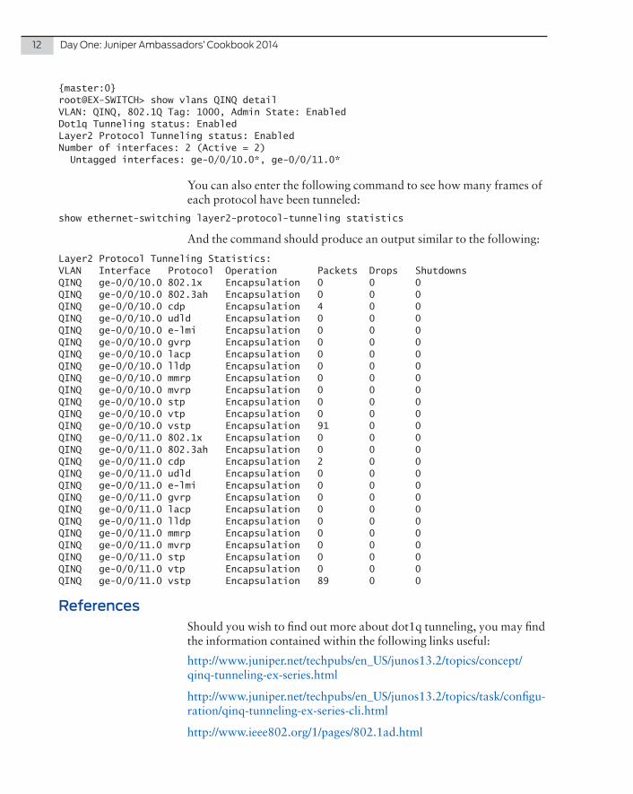
{master:0}root@EX-SWITCH> show vlans QINQ detail VLAN: QINQ, 802.1Q Tag: 1000, Admin State: EnabledDot1q Tunneling status: EnabledLayer2 Protocol Tunneling status: EnabledNumber of interfaces: 2 (Active = 2) Untagged interfaces: ge-0/0/10.0*, ge-0/0/11.0*
You can also enter the following command to see how many frames of each protocol have been tunneled:
show ethernet-switching layer2-protocol-tunneling statistics
And the command should produce an output similar to the following:
Layer2 Protocol Tunneling Statistics:VLAN Interface Protocol Operation Packets Drops ShutdownsQINQ ge-0/0/10.0 802.1x Encapsulation 0 0 0 QINQ ge-0/0/10.0 802.3ah Encapsulation 0 0 0 QINQ ge-0/0/10.0 cdp Encapsulation 4 0 0 QINQ ge-0/0/10.0 udld Encapsulation 0 0 0 QINQ ge-0/0/10.0 e-lmi Encapsulation 0 0 0 QINQ ge-0/0/10.0 gvrp Encapsulation 0 0 0 QINQ ge-0/0/10.0 lacp Encapsulation 0 0 0 QINQ ge-0/0/10.0 lldp Encapsulation 0 0 0 QINQ ge-0/0/10.0 mmrp Encapsulation 0 0 0 QINQ ge-0/0/10.0 mvrp Encapsulation 0 0 0 QINQ ge-0/0/10.0 stp Encapsulation 0 0 0 QINQ ge-0/0/10.0 vtp Encapsulation 0 0 0 QINQ ge-0/0/10.0 vstp Encapsulation 91 0 0 QINQ ge-0/0/11.0 802.1x Encapsulation 0 0 0 QINQ ge-0/0/11.0 802.3ah Encapsulation 0 0 0 QINQ ge-0/0/11.0 cdp Encapsulation 2 0 0 QINQ ge-0/0/11.0 udld Encapsulation 0 0 0 QINQ ge-0/0/11.0 e-lmi Encapsulation 0 0 0 QINQ ge-0/0/11.0 gvrp Encapsulation 0 0 0 QINQ ge-0/0/11.0 lacp Encapsulation 0 0 0 QINQ ge-0/0/11.0 lldp Encapsulation 0 0 0 QINQ ge-0/0/11.0 mmrp Encapsulation 0 0 0 QINQ ge-0/0/11.0 mvrp Encapsulation 0 0 0 QINQ ge-0/0/11.0 stp Encapsulation 0 0 0 QINQ ge-0/0/11.0 vtp Encapsulation 0 0 0 QINQ ge-0/0/11.0 vstp Encapsulation 89 0 0
ReferencesShould you wish to find out more about dot1q tunneling, you may find the information contained within the following links useful:
http://www.juniper.net/techpubs/en_US/junos13.2/topics/concept/qinq-tunneling-ex-series.html
http://www.juniper.net/techpubs/en_US/junos13.2/topics/task/configu-ration/qinq-tunneling-ex-series-cli.html
http://www.ieee802.org/1/pages/802.1ad.html

Problem
Modern offices employ a diverse array of network-enabled devices and security requirements. The standard office-network-ing environment requires Internet access, shared printers, and the potential for peer-to-peer sharing within the LAN. Even then, small organizations begin collecting a variety of special purpose servers for shared applications, files, and resources. While industrial SCADA controllers are network-enabled to interoper-ate and control the manufacturing process, each area has its own traffic patterns and security requirements. Thus, the traditional single-zone small business firewall is not optimal for these new configurations despite the relatively small device counts.
Solution
To solve this predicament, managed switching is deployed along with a full-feature multi-zone firewall using an SRX Series and an EX Series switch. This permits the full segmentation of devices by security needs and allows the control of permitted connections between the device zones.
The design allows direct communications between the end user computers and printers. All other zones are secured on the SRX Series and have the ability for tighter security restrictions as outlined in Table 2.1.
Recipe 2
Managed Switching for a Small Office Network
by Steve Puluka
14 DayOne:JuniperAmbassadors’Cookbook2014
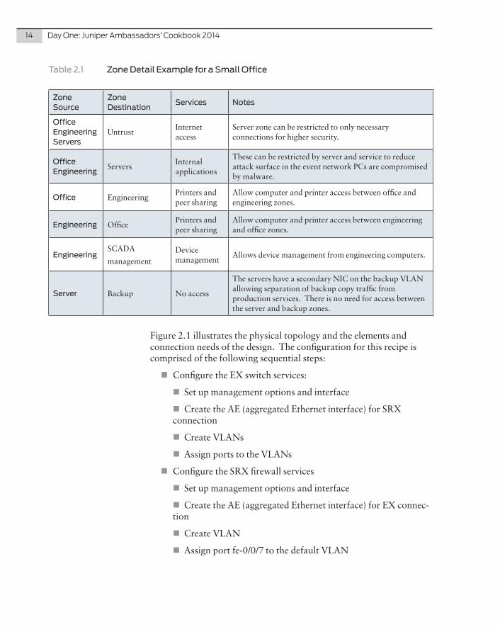
Table 2.1 Zone Detail Example for a Small Office
Zone Source
Zone Destination
Services Notes
OfficeEngineeringServers
UntrustInternet access
Server zone can be restricted to only necessary connections for higher security.
OfficeEngineering
ServersInternal applications
These can be restricted by server and service to reduce attack surface in the event network PCs are compromised by malware.
Office EngineeringPrinters and peer sharing
Allow computer and printer access between office and engineering zones.
Engineering OfficePrinters and peer sharing
Allow computer and printer access between engineering and office zones.
EngineeringSCADA
managementDevice management
Allows device management from engineering computers.
Server Backup No access
The servers have a secondary NIC on the backup VLAN allowing separation of backup copy traffic from production services. There is no need for access between the server and backup zones.
Figure 2.1 illustrates the physical topology and the elements and connection needs of the design. The configuration for this recipe is comprised of the following sequential steps:
� Configure the EX switch services:
� Set up management options and interface
� Create the AE (aggregated Ethernet interface) for SRX connection
� Create VLANs
� Assign ports to the VLANs
� Configure the SRX firewall services
� Set up management options and interface
� Create the AE (aggregated Ethernet interface) for EX connec-tion
� Create VLAN
� Assign port fe-0/0/7 to the default VLAN
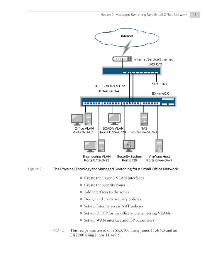
Recipe2:ManagedSwitchingforaSmallOfficeNetwork 15
Internet
Internet Service Ethernet
SRX 0/0
SRX - 0/7
EX - me0.0
AE - SRX 0/1 & 0/2
EX 0/40 & 0/41
Office VLANPorts 0/0-0/11
SCADA VLANPorts 0/24-0/29
NASPorts 0/42-0/43
Engineering VLANPorts 0/12-0/23
Security SystemPort 0/39
VmWare HostPorts 0/44-04/7
Figure 2.1 The Physical Topology for Managed Switching for a Small Office Network
� Create the Layer 3 VLAN interfaces
� Create the security zones
� Add interfaces to the zones
� Design and create security policies
� Setvup Internet access NAT policies
� Setvup DHCP for the office and engineering VLANs
� Setvup WAN interface and ISP parameters
NOTE This recipe was tested on a SRX100 using Junos 11.4r5.5 and an EX2200 using Junos 11.4r7.5.

16 DayOne:JuniperAmbassadors’Cookbook2014
Configure EX Services
Step 1: Set up Management Options and Interface
set system services sshset system services web-management httpsset system services web-management https system-generated-certificate
Next remove the default configuration on all ports to start with a clean slate for our setup:
edit interfacesdelete confirm deletion of all interfacestop
Now we will set up the management port:
set interfaces me0.0 family inet address 10.0.1.11/24 set routing-options static route 0.0.0.0/0 next-hop 10.0.1.1
Step 2: Create the AE (Aggregated Ethernet Interface) for the SRX Series Connection
First create the AE interface and add the two ports to the LAG group while setting active mode for LACP. Active mode must be on at least one side of the LAG for the connection to establish. Then you make the AE bundle a trunk port with all VLANs:
set chassis aggregated-devices ethernet device-count 1set interfaces ge-0/0/40 ether-options 802.3ad ae0set interfaces ge-0/0/40 ether-options link-mode full-duplexset interfaces ge-0/0/40 ether-options speed 100mset interfaces ge-0/0/41 ether-options 802.3ad ae0set interfaces ge-0/0/41 ether-options link-mode full-duplexset interfaces ge-0/0/41 ether-options speed 100mset interfaces ae0 aggregated-ether-options lacp active periodic fastset interfaces ae0 unit 0 family ethernet-switching port-mode trunk vlan members all
Step 3: Create the VLANs
Next create the VLANs assigning the name and VLAN tag to each one per the network diagram:
set vlans default vlan-id 1set vlans backup vlan-id 2set vlans server vlan-id 3set vlans scada vlan-id 4set vlans office vlan-id 10set vlans engineering vlan-id 20

Recipe2:ManagedSwitchingforaSmallOfficeNetwork 17
Step 4: Assign Ports to the VLANs
Next assign the ports allocated to each VLAN to the correct VLAN. This first series allows us to assign port ranges to all the same VLAN together:
set interfaces interface-range office-ports member ge-0/0/[0-11]set interfaces interface-range office-ports unit 0 family ethernet-switchingset vlans office interface office-portsset interfaces interface-range engineering-ports member ge-0/0/[12-23]set interfaces interface-range engineering-ports unit 0 family ethernet-switchingset vlans engineering interface engineering-portsset interfaces interface-range scada-ports member ge-0/0/[24-29]set interfaces interface-range scada-ports unit 0 family ethernet-switchingset vlans scada interface scada-ports
Now assign the individual ports to the specific remaining VLANs starting with the server VLAN. Port 39 has the security system:
set vlans server interface ge-0/0/39set interfaces ge-0/0/39.0 family ethernet-switching
Ports 44 and 45 are the VMware production network link. VMware connects two access ports in the same VLAN and shares bandwidth to all the production servers:
set vlans server interface ge-0/0/44set interfaces ge-0/0/44.0 family ethernet-switchingset vlans server interface ge-0/0/45set interfaces ge-0/0/45.0 family ethernet-switching
The backup VLAN connects to both the VMware server and the NAS for access to backup storage from the secondary server NIC:
set vlans backup interface ge-0/0/42set interfaces ge-0/0/42.0 family ethernet-switchingset vlans backup interface ge-0/0/46set interfaces ge-0/0/46.0 family ethernet-switching
The management network provides a connection to the VMware server and NAS management interface:
set vlans default interface ge-0/0/43set interfaces ge-0/0/43.0 family ethernet-switchingset vlans default interface ge-0/0/47set interfaces ge-0/0/47.0 family ethernet-switching

18 DayOne:JuniperAmbassadors’Cookbook2014
Configure SRX Services
Step 1: Set up Management Options and Interface
All management services are enabled by default on the branch SRX so you must remove the Telnet and HTTP management that transmit passwords in plain text on the network. Also change the management VLAN from vlan.0 to vlan.1. (SSH is already enabled so it does not need to be added.)
delete system services telnetdelete system services web-management httpdelete system services web-management https interface vlan.0set system services web-management https interface vlan.1
Step 2: Create the AE (aggregated Ethernet interface) for EX Connection
Create the AE interface and add the two ports to the LAG group while setting active mode for LACP. Active mode must be on at least one side of the LAG for the connection to establish. Then make the AE bundle a trunk port with all VLANs:
set chassis aggregated-devices ethernet device-count 1delete interfaces fe-0/0/1delete interfaces fe-0/0/2set interfaces fe-0/0/1 fastether-options 802.3ad ae0set interfaces fe-0/0/1 link-mode full-duplexset interfaces fe-0/0/1 speed 100mset interfaces fe-0/0/2 fastether-options 802.3ad ae0set interfaces fe-0/0/2 link-mode full-duplexset interfaces fe-0/0/2 speed 100mset interfaces ae0 aggregated-ether-options lacp active periodic fastset interfaces ae0 unit 0 family ethernet-switching port-mode trunk vlan members all
Step 3: Create VLANs
Next create the VLANs and assign the name and VLAN tag to each one per the network diagram. You also need to remove the trust VLAN and interface assignment defaults from the branch SRX default configuration:
delete vlans vlan-trustdelete interfaces vlan.0delete interfaces fe-0/0/3delete interfaces fe-0/0/4delete interfaces fe-0/0/5delete interfaces fe-0/0/6delete interfaces fe-0/0/7
Remove all of the current security configuration:
edit securitydelete

Recipe2:ManagedSwitchingforaSmallOfficeNetwork 19
confirm the delete for the entire stanzatopset vlans default vlan-id 1set vlans backup vlan-id 2set vlans server vlan-id 3set vlans scada vlan-id 4set vlans office vlan-id 10set vlans engineering vlan-id 20
Step 4: Assign Interface fe-0/0/7 to the Default VLAN
The management port of the EX switch is connected to the SRX port fe-0/0/7 and it needs to be assigned to the default VLAN for manage-ment access. This is the only access port on the SRX. All the other interfaces used here will be Layer 3 VLAN interfaces:
set vlans default interface fe-0/0/7set interfaces fe-0/0/7.0 family ethernet-switching
Step 5: Create the Layer 3 VLAN Interfaces
Now we set up the Layer 3 VLAN interfaces for all the subnets in our network:
set interfaces vlan unit 1 family inet address 10.0.1.1/24set vlans default l3-interface vlan.1
set interfaces vlan unit 2 family inet address 10.0.2.1/24set vlans backup l3-interface vlan.2
set interfaces vlan unit 3 family inet address 10.0.3.1/24set vlans server l3-interface vlan.3
set interfaces vlan unit 4 family inet address 10.0.4.1/24set vlans scada l3-interface vlan.4
set interfaces vlan unit 10 family inet address 10.0.5.1/24set vlans office l3-interface vlan.10
set interfaces vlan unit 20 family inet address 10.0.6.1/24set vlans engineering l3-interface vlan.20
Step 6: Create the Security Zones
Now let’s create the security zones for each VLAN. The management, office, and engineering VLANs require system services to be enabled. The management VLAN needs it for access to the SRX for managing the device. The office and engineering VLANs require access to the DHCP server to work. For higher security, you could limit this access to just the required services:
set security zones security-zone mgmt

20 DayOne:JuniperAmbassadors’Cookbook2014
set security zones security-zone mgmt host-inbound-traffic system-services allset security zones security-zone backupset security zones security-zone backup host-inbound-traffic system-services pingset security zones security-zone serverset security zones security-zone server host-inbound-traffic system-services pingset security zones security-zone scadaset security zones security-zone scada host-inbound-traffic system-services pingset security zones security-zone officeset security zones security-zone office host-inbound-traffic system-services pingset security zones security-zone engineeringset security zones security-zone engineering host-inbound-traffic system-services pingset security zones security-zone untrustset security zones security-zone untrust host-inbound-traffic system-services ping
Step 7: Add Interfaces to the Zones
Now assign the interfaces to their respective zones to allow the traffic through the SRX to be correctly identified as to which zone is the source and which is the destination:
set security zones security-zone mgmt interfaces vlan.1set security zones security-zone backup interfaces vlan.2set security zones security-zone server interfaces vlan.3set security zones security-zone scada interfaces vlan.4set security zones security-zone office interfaces vlan.10set security zones security-zone engineering interfaces vlan.20set security zones security-zone untrust interfaces fe-0/0/0
Step 8: Design and Create Security Policies
Create an address book for the subnet assigned to each zone:
set security zones security-zone mgmt address-book address mgmt-lan 10.0.1.0/24set security zones security-zone backup address-book address backup-lan 10.0.2.0/24set security zones security-zone server address-book address server-lan 10.0.3.0/24set security zones security-zone scada address-book address scada-lan 10.0.4.0/24set security zones security-zone office address-book address office-lan 10.0.5.0/24set security zones security-zone engineering address-book address engineering-lan 10.0.6.0/24
Create the policy list outlined in Table 2.1 to allow the zone-to-zone communications desired and block all others.
Allow Internet access from office zone:
edit security policies from-zone office to-zone untrust policy internetset match source-address office-lanset match destination-address anyset match application anyset then permitset then log session-closetop

Recipe2:ManagedSwitchingforaSmallOfficeNetwork 21
Allow Internet access from engineering zone:
edit security policies from-zone engineering to-zone untrust policy internetset match source-address engineering-lanset match destination-address anyset match application anyset then permitset then log session-closetop
Allow Internet access from the server zone:
edit security policies from-zone server to-zone untrust policy internetset match source-address server-lanset match destination-address anyset match application anyset then permitset then log session-closetop
Allow office access to engineering:
edit security policies from-zone office to-zone engineering policy engineering-accessset match source-address office-lanset match destination-address engineering-lanset match application anyset then permitset then log session-closetop
Allow engineering access to office:
edit security policies from-zone engineering to-zone office policy office-accessset match source-address engineering-lanset match destination-address office-lanset match application anyset then permitset then log session-closetop
Allow office access to servers:
edit security policies from-zone office to-zone server policy server-accessset match source-address office-lanset match destination-address server-lanset match application anyset then permitset then log session-closetop
Allow engineering access to servers:
edit security policies from-zone engineering to-zone server policy server-accessset match source-address engineering-lanset match destination-address server-lan

22 DayOne:JuniperAmbassadors’Cookbook2014
set match application anyset then permitset then log session-closetop
Allow engineering to access SCADA:
edit security policies from-zone engineering to-zone scada policy scada-accessset match source-address engineering-lanset match destination-address scada-lanset match application anyset then permitset then log session-closetop
Allow engineering to access the management LAN:
edit security policies from-zone engineering to-zone mgmt policy mgmt-accessset match source-address engineering-lanset match destination-address mgmt-lanset match application anyset then permitset then log session-closetop
Step 9: Set up Internet Access NAT Policies
Create the source NAT rules that allow the office, engineering, and server zones to work on the Internet:
edit security nat source rule-set office-untrustset from zone officeset to zone untrustset rule source-nat-office match source-address 0.0.0.0/0set rule source-nat-office then source-nat interfacetopedit security nat source rule-set engineering-untrustset from zone engineeringset to zone untrustset rule source-nat-engineering match source-address 0.0.0.0/0set rule source-nat-engineering then source-nat interfacetopedit security nat source rule-set server-untrustset from zone serverset to zone untrustset rule source-nat-server match source-address 0.0.0.0/0set rule source-nat-server then source-nat interfacetop
Step 10: Set up WAN Interface and ISP Parameters
Now place the public address onto interface fe-0/0/0 and install the default route for the ISP:
set interface fe-0/0/0.0 family inet address 2.2.2.2/24set routing-options static route 0.0.0.0/0 next-hop 2.2.2.1

Recipe2:ManagedSwitchingforaSmallOfficeNetwork 23
Step 11: Set up DHCP for the Office and Engineering VLANs
Remove the default DHCP server settings:
delete system services dhcp routerdelete system services dhcp pool 192.168.1.0/24
Now create a DHCP server for both computer VLANs:
set system services dhcp router 10.0.5.1set system services dhcp pool 10.0.5.0/24 address-range low 10.0.5.10 high 10.0.5.50set system services dhcp router 10.0.6.1set system services dhcp pool 10.0.6.0/24 address-range low 10.0.6.10 high 10.0.6.50set system services dhcp name-server 8.8.8.8set system services dhcp name-server 8.8.4.4
Verification
Step 1: Aggregated Interface Verification
This will confirm that the AE link is up and active between the SRX and EX:
show lacp interfaces ae0
On the EX:
Aggregated interface: ae0 LACP state: Role Exp Def Dist Col Syn Aggr Timeout Activity ge-0/0/40 Actor No No Yes Yes Yes Yes Fast Active ge-0/0/40 Partner No No Yes Yes Yes Yes Fast Active ge-0/0/41 Actor No No Yes Yes Yes Yes Fast Active ge-0/0/41 Partner No No Yes Yes Yes Yes Fast Active LACP protocol: Receive State Transmit State Mux State ge-0/0/40 Current Fast periodic Collecting distributing ge-0/0/41 Current Fast periodic Collecting distributing
On the SRX:
Aggregated interface: ae0 LACP state: Role Exp Def Dist Col Syn Aggr Timeout Activity fe-0/0/1 Actor No No Yes Yes Yes Yes Fast Active fe-0/0/1 Partner No No Yes Yes Yes Yes Fast Active fe-0/0/2 Actor No No Yes Yes Yes Yes Fast Active fe-0/0/2 Partner No No Yes Yes Yes Yes Fast Active LACP protocol: Receive State Transmit State Mux State fe-0/0/1 Current Fast periodic Collecting distributing fe-0/0/2 Current Fast periodic Collecting distributing
VLAN Verification
These commands verify the port configurations for the multiple VLANs: show vlans.

24 DayOne:JuniperAmbassadors’Cookbook2014
EX2200:
Name Tag Interfacesbackup 2 ae0.0*, ge-0/0/42.0, ge-0/0/46.0default 1 ae0.0*engineering 20 ae0.0*, ge-0/0/12.0*, ge-0/0/13.0, ge-0/0/14.0, ge-0/0/15.0, ge-0/0/16.0, ge-0/0/17.0, ge-0/0/18.0, ge-0/0/19.0, ge-0/0/ge-0/0/21.0, ge-0/0/22.0, ge-0/0/23.0office 10 ae0.0*, ge-0/0/0.0, ge-0/0/1.0, ge-0/0/2.0, ge-0/0/3.0, ge-0/0/4.0, ge-0/0/5.0, ge-0/0/6.0, ge-0/0/7.0, ge-0/0/8.0, ge-0/0/9.0, ge-0/0/10.0, ge-0/0/11.0scada 4 a/0/25.0, ge-0/0/26.0, ge-0/0/27.0, ge-0/0/28.0, ge-0/0/29.0server 3 0/0/43.0, ge-0/0/44.0, ge-0/0/45.0, ge-0/0/47.0
SRX100:
Name Tag Interfacesbackup 2 ae0.0*default 1 ae0.0*, fe-0/0/7.0*engineering 20 ae0.0*office 10 ae0.0*scada 4 ae0.0*server 3 ae0.0*
References
Security Policies:
http://www.juniper.net/techpubs/en_US/junos11.4/topics/concept/policy-overview.html
NAT Policies:
http://kb.juniper.net/library/CUSTOMERSERVICE/technotes/Junos_NAT_Examples.pdf
Aggregated Ethernet:
http://www.juniper.net/techpubs/en_US/junos12.1/topics/concept/interface-security-aggregated-ethernet-understanding.html
VLANs:
http://www.juniper.net/techpubs/en_US/junos12.3/topics/task/configu-ration/bridging-vlans-ex-series-cli.html
DHCP:
http://www.juniper.net/techpubs/en_US/junos11.4/topics/concept/security-dhcp-server-operation-understanding.html

In Junos OS version 12.1X47, Juniper introduced the integrated user firewall. This solution provides for transparent authentica-tion of user credentials against active directory servers without the use of a UAC appliance. Cool. Let’s try it out in the lab.
Problem
Customers are looking for enhanced security controls prior to granting access to protected resources. Prior to Junos 12.1X47, this could only be achieved if an SRX Series was deployed in conjunction with a Juniper UAC appliance, which increased both the complexity and cost of an SRX deployment.
Solution
Junos 12.1X47 provides on-box authentication and authoriza-tion (AA). Authentication is done against an Active Directory (AD) server with the SRX polling the AD device for login infor-mation through the Windows Management Instrumentation (WMI) interface. Access to resources is then granted through source-identity policy statements, which can be either user or group-based. Group-based access requires establishing a second connection to the AD server through LDAP.
NOTE While simple and easy to execute, this solution does not scale well and is best used for smaller environments.
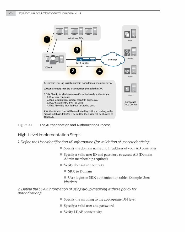
The mechanics of what happens during the authentication and authorization (application of policy) process are illustrated in Figure 3.1.
Recipe 3
Configuring a SRX Series Integrated Firewall
by Kevin Barker
26 DayOne:JuniperAmbassadors’Cookbook2014
Video
Apps
Data
Finance
Windows ADs
Client
CorporateData Center
Internet
SRX Series
1
2 4
3
1. Domain user log ins into domain from domain member device.
2. User attempts to make a connection through the SRX.
3. SRX Checks local tables to see if user is already authenticated. 1. If so, user continues 2. If no local authentication, then SRX queries AD 3. If AD has an entry it will be used 4. If no AD entry then fallback to captive portal
4. Authenticated user will be evaluated by policy according to the �rewall rulebase. If tra�c is permitted then user will be allowed to continue.
Figure 3.1 The Authentication and Authorization Process
High-LevelImplementationSteps
1 . Define the User Identification AD Information (for validation of user credentials):
� Specify the domain name and IP address of your AD controller
� Specify a valid user ID and password to access AD (Domain Admin membership required)
� Verify domain connectivity
� SRX to Domain
� User logins in SRX authentication table (Example User: kbarker)
2 . Define the LDAP Information (if using group mapping within a policy for authorization):
� Specify the mapping to the appropriate DN level
� Specify a valid user and password
� Verify LDAP connectivity

Recipe3:ConfiguringaSRXSeriesIntegratedFirewall 27
3 . Define the Source-identification Rules on the Policy:
� Test access to protected resources with Ping (User = kbarker or group = employees)
� Examine security flows
� Examine policy log
DetailedImplementationSteps
1 . Set AD Connectivity:
root@host# set services user-identification active-directory-access domain itgmeeting.com domain-controller ITG-DC01 address 192.168.30.31root@host# set services user-identification active-directory-access domain itgmeeting.com user Ad-Loginroot@host# set services user-identification active-directory-access domain itgmeeting.com user password "$9$8spLxN-VYJUHvWY4aZkqO1RhlK"user@host> show services user-identification active-directory-access domain-controller status Domain: itgmeeting.com Domain controller Address Status ITG-DC01 192.168.30.31 Connected
user@host> show services user-identification active-directory-access active-directory-authentication-table allDomain: itgmeeting.comTotal entries: 3Source IP Username groups state192.168.30.1 kbadmin Valid192.168.30.80 Pending 192.168.70.154 kbarker Valid
Domain: NULLTotal entries: 2Source IP Username groups state192.168.10.18 Invalid 192.168.10.252 Invalid
2 . Set LDAP Connectivity for Group Mapping:
root@host# set services user-identification active-directory-access domain itgmeeting.com user-group-mapping ldap base DC=itgmeeting,DC=comroot@host# set services user-identification active-directory-access domain itgmeeting.com user-group-mapping ldap user AD-Loginroot@host# set services user-identification active-directory-access domain itgmeeting.com user-group-mapping ldap user password "$9$cyKSreKMXVs4RhXNdboan/CtBI
user@host> show services user-identification active-directory-access user-group-mapping status domain itgmeeting.com Domain: itgmeeting.comLDAP server Port Last-query-status Last-query-time 192.168.30.31 389 Query success 2014-08-12 12:29:33

28 DayOne:JuniperAmbassadors’Cookbook2014
3 . Create the Policy Setup:
root@host# set security policies from-zone trust to-zone itg-data-center policy allow-by-user match source-identity "itgmeeting.com\kbadmin" >>> For user based authorizationroot@host# set security policies from-zone trust to-zone itg-data-center policy allow-by-group match source-identity "itgmeeting.com\employees" >>> For AD group based authorization
user@host> show security flow session destination-prefix 192.168.3.175Session ID: 33437, Policy name: allow-by-user/20, Timeout: 2, Valid In: 192.168.70.154/214 --> 192.168.3.175/1;icmp, If: vlan.70, Pkts: 1, Bytes: 60 Out: 192.168.3.175/1 --> 192.168.70.154/214;icmp, If: st0.0, Pkts: 1, Bytes: 60
user@host> show log sec-pol-log | last 20 | match 192.168.3.175Aug 11 16:46:01 itg-main RT_FLOW: RT_FLOW_SESSION_CREATE: session created 192.168.70.154/214->192.168.3.175/1 icmp 192.168.70.154/214->192.168.3.175/1 None None 1 allow-by-user trust itg-data-center 33437 kbarker(N/A) vlan.70 UNKNOWN UNKNOWN UNKNOWNAug 11 16:46:05 itg-main RT_FLOW: RT_FLOW_SESSION_CLOSE: session closed response received: 192.168.70.154/214->192.168.3.175/1 icmp 192.168.70.154/214->192.168.3.175/1 None None 1 allow-by-user trust itg-data-center 33437 1(60) 1(60) 4 UNKNOWN UNKNOWN kbarker(N/A) vlan.70 UNKNOWN
DiscussionVerifying user identity prior to granting access to resources is becom-ing an essential business requirement for most companies today. Prior to the release of this feature it was only possible through SRX Series and UAC integration. Now companies can leverage their Active Directory infrastructure and provide additional authentication and authorization capabilities directly from the SRX!
NOTE The X47 release requires a minimum hardware specification of H2-based units for the branch platform (SRX100H2 through SRX240H2). See the release notes for the Junos 12.1X47 code.
Up to five AD severs can be specified for the lower-level branch devices (SRX100H2 – SRX240H2) and up to ten for all other SRX devices.
ReferencesSee the release notes for the Junos 12.1X47 code: http://www.juniper.net/techpubs/en_US/junos12.1x47/information-products/topic-collections/release-notes/12.1x47/junos-release-notes-12.1X47.pdf
Documentation for configuring the Integrated User Firewall may be found at: http://www.juniper.net/techpubs/en_US/junos12.1x47/information-products/pathway-pages/srx-series/index.html

Problem
The Junos Space Security Director application is well-suited for managing several firewalls to many hundreds of firewalls, de-pending on your network. That’s because firewall policies, VPNs, NAT, and IPS policies are centrally managed and the settings configured in one place can apply to many devices.
The problem is that this is a change to our industry. Some net-work engineers get nervous without the Junos CLI, and the thought of configuring hundreds of firewalls all at once, is, well, nerve-racking. While you can deploy multiple devices at the same time there is a lot of flexibility in Space Security Director, so settings for each individual device can be fine-tuned.
In this recipe, a simple network (see Figure 4.1) is used to show how Security Director allows for centralized security policy configuration. There are only two SRX devices (SRX-A and SRX-B) here for the sake of instruction, but the example can be easily scaled. The task is as follows:
Allow communication for all users from the Trust to Untrust zone on both firewalls using HTTP, HTTPS, and SSH services;
And, allow Host-1 (having an IP address of 10.37.0.1) in the SRX-A device’s Trust zone to communicate to an external server (with an IP of 5.5.5.5) in the Untrust zone using HTTP service on non-standard port 8080.
NOTE This recipe uses version 13.3R1 of the Junos Space Security Director application.
Recipe 4
Deploying Firewall Policies on Multiple Devices with Junos Space Security Director
by Petr Klemaj

30 DayOne:JuniperAmbassadors’Cookbook2014
External Server5.5.5.5
Host-110.37.0.1 Office A
10.37.0.0/24Office B
10.38.0.0/24
10.37.0.254
1.37.1.1 1.38.1.1
10.38.0.254
UNTRUST zone UNTRUST zone
TRUST zone TRUST zone
SRX-A SRX-B
Figure 4.1 Topology Used for Deploying Firewall Policies on Multiple Devices with Junos Space Security Director. Junos Space is managing SRX-A and SRX-B Using Out-of-band Management Network (not shown).
Solution
This recipe assumes that the SRX-A and SRX-B devices have already been added to Junos Space. In this case, you should see them in Devices > Device Management (Figure 4.2). To learn how to add devices to Junos Space please see its technical documentation, the links for which are at the end of this recipe.
Now, in the Security Director application (choose Security Director in the drop-down list in the upper-left corner of the screen), navigate to the Firewall Policies menu item (see Figure 4.3):

Recipe4:DeployingFirewallPoliciesonMultipleDeviceswithJunosSpaceSecurityDirector 31
Figure 4. 2 Device Management Screen with SRX-A and SRX-B Already Under Management of Junos Space
Figure 4.3 Firewall Policies Screen in Security Director

32 DayOne:JuniperAmbassadors’Cookbook2014
You will see that All Devices Policy is already present in the list. Its rules apply to all Security Director devices, so you could use it for our task. However, in the future you may want to add more devices that do not need the rules of our task, so instead of using All Devices Policy let’s create a new group policy just for our recipe’s SRX-A and SRX-B devices. Click on the Create Policy button (green button that looks like a folder with a plus sign). A separate window opens (see Figure 4.4):
Figure 4.4 The Create Policy Window
Enter the policy name GroupFirewallPolicy and move both available devices (SRX-A and SRX-B) to the Selected list at the bottom of the window. This will assign the policy to those devices. Leave all other op-tions as their defaults. Click Create and the new policy will be seen in the policy list.
Now select the newly created GroupFirewallPolicy and use the green lock button to lock the policy to prevent further editing.
NOTE Policy locking has been implemented in Security Director to prevent conflicts between changes made by different administrators.

Recipe4:DeployingFirewallPoliciesonMultipleDeviceswithJunosSpaceSecurityDirector 33
Click on Create Post-Rule. At this point, several levels of security policies have been used in Security Director and the post-rules will order them. In the CLI of the security devices, Security Director creates security policies in the following order:
All Devices Pre-Rules > Group Pre-Rules > Device Rules > Group Post-Rules > All Devices Post-Rules
For this recipe, let’s use Post-Rules at the group level so that device-specific rules can override them (if needed).
In the newly created rule, select Source/Zone as Trust and Destination/Zone as Untrust. Change the Destination/Action from Deny to Permit by clicking on it and making the selection from a list. Click on Service to choose HTTP, HTTPS, and SSH for this policy rule (see Figure 4.5). Click on the OK button:
Figure 4.5 Creating a Post-Rule in GroupFirewallPolicy
Now that the rule is created, click the Save button at the bottom of the screen and also click the green lock button to unlock the policy (this is a best practice routine that allows other administrators to edit the policy if needed).
Note that at this time, the policy has been saved in Security Director, but it has not been pushed to the SRX devices yet.
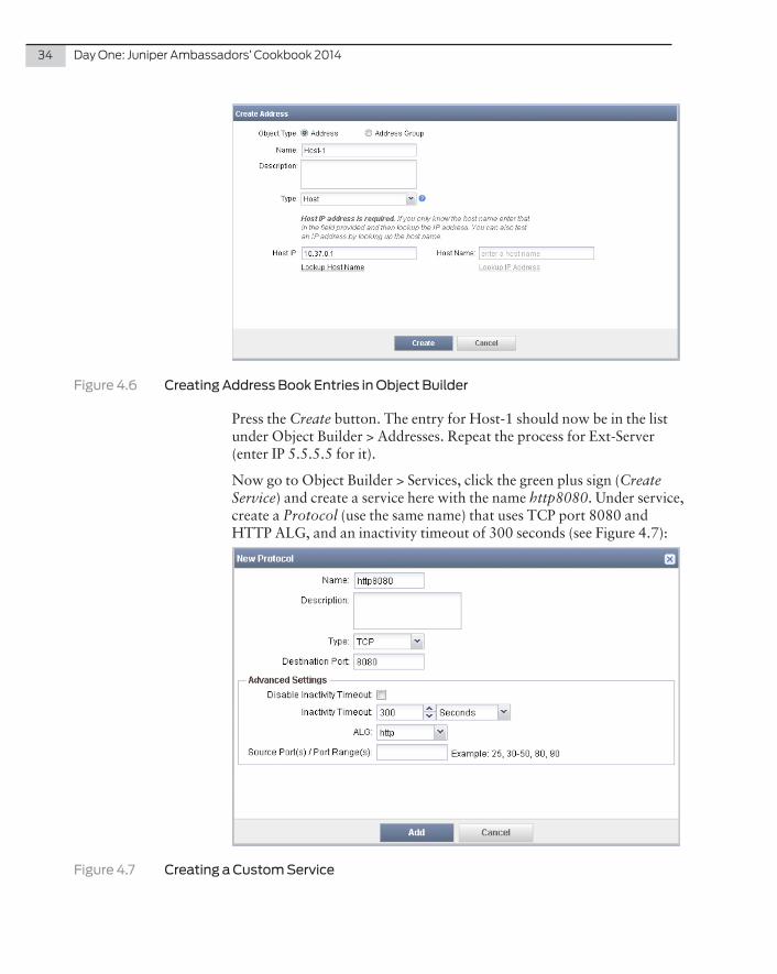
For the second task – HTTP on custom port 8080 between Host-1 and External Server) – let’s create several custom objects. Go to Object Builder > Addresses, click a green plus sign (Create Address appears when moused over) and create an entry for Host-1 (see Figure 4.6):
34 DayOne:JuniperAmbassadors’Cookbook2014
Figure 4.6 Creating Address Book Entries in Object Builder
Press the Create button. The entry for Host-1 should now be in the list under Object Builder > Addresses. Repeat the process for Ext-Server (enter IP 5.5.5.5 for it).
Now go to Object Builder > Services, click the green plus sign (Create Service) and create a service here with the name http8080. Under service, create a Protocol (use the same name) that uses TCP port 8080 and HTTP ALG, and an inactivity timeout of 300 seconds (see Figure 4.7):
Figure 4.7 Creating a Custom Service

Recipe4:DeployingFirewallPoliciesonMultipleDeviceswithJunosSpaceSecurityDirector 35
Go back to the Firewall Policies menu item and expand the GroupFire-wallPolicy with a plus sign that is to the left of it (it will show SRX-A and SRX-B device policies under the group policy GroupFirewallPolicy – see Figure 4.8). Click SRX-A policy and lock it for edit with the lock sign. Click on Create Device Rule. Select Trust and Untrust as source and destination zones, respectively. Select Host-1 as a source address, Ext-Server as a destination address, and select the action as Permit. Select http8080 as a service. Now save the policy and unlock it:
Figure 4.8 Creating a Firewall Policy Rule for SRX-A
Now, right-click GroupFirewallPolicy and select Publish Policy. In the window that opens (see Figure 4.9) click on Publish and Update. A job manager window opens and you should soon see a success message similar to one shown in Figure 4.10. In case of an error, details of the problem are presented in the same window:

36 DayOne:JuniperAmbassadors’Cookbook2014
Figure 4.9 Publishing and Updating the Policy
Figure 4.10 Results of the Update Device Job
You will now need to publish the SRX-A policy (which is under GroupFirewallPolicy in the policy tree) in a way that is similar to what you did it for GroupFirewallPolicy. Just use the Publish and Update button at the end.
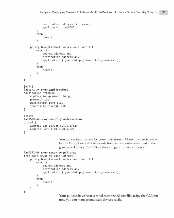
Now you can see the results of your work on your firewalls. On SRX-A, the configuration created by Security Director is as follows:
lab@SRX-A# show security policies from-zone TRUST to-zone UNTRUST { policy Device-Zone-1 { match { source-address Host-1;
Recipe4:DeployingFirewallPoliciesonMultipleDeviceswithJunosSpaceSecurityDirector 37
destination-address Ext-Server; application http8080; } then { permit; } } policy GroupFirewallPolicy-Zone-Post-1 { match { source-address any; destination-address any; application [ junos-http junos-https junos-ssh ]; } then { permit; } }}
[edit]lab@SRX-A# show applications application http8080 { application-protocol http; protocol tcp; destination-port 8080; inactivity-timeout 300;}
[edit]lab@SRX-A# show security address-book global { address Ext-Server 5.5.5.5/32; address Host-1 10.37.0.1/32;}
You can see that the rule for communication of Host-1 to Ext-Server is before GroupFirewallPolicy’s rule because post-rules were used in the group-level policy. On SRX-B, the configuration is as follows:
lab@SRX-B# show security policies from-zone Trust to-zone Untrust { policy GroupFirewallPolicy-Zone-Post-1 { match { source-address any; destination-address any; application [ junos-http junos-https junos-ssh ]; } then { permit; } }}
Your policies have been created as expected, just like using the CLI, but now you can manage and scale devices easily.

38 DayOne:JuniperAmbassadors’Cookbook2014
References
Junos Space technical documentation, including Security Director application documentation, is available at: https://www.juniper.net/techpubs/en_US/release-independent/junos-space/index.html
Juniper Learning Bytes contain several useful Junos Space-related videos: https://learningportal.juniper.net/juniper/user_activity_info.aspx?id=5853
In case you have a question or problem, try searching the Knowledge Base: http://kb.juniper.net

Problem
Most enterprises today use Network Address Translation (NAT) for IPv4 traffic leaving their networks but continue to deploy and configure devices on a case-by-case basis. Junos Space Security Director allows an administrator to centrally manage NAT policies (or rules) on many devices allowing your network to be more nimble and flexible.
To show off the flexibility of Junos Space Security Director, this recipe configures both the source and destination NAT in our example network (see Figure 5.1) according to the following tasks:
� All communication from Trust to Untrust zone must be source-NAT’ed using egress interface IP address of the corresponding SRX device;
� And, for traffic entering the external interface’s address 1.37.1.1 of SRX-A on destination port 9090, destination NAT must be assigned to the address 10.37.0.1 of Host-1.
NOTE This recipe uses version 13.3R1 of Junos Space Security Director applications.
Recipe 5
Deploying NAT Policies with Junos Space Security Director
by Petr Klemaj

40 DayOne:JuniperAmbassadors’Cookbook2014
External Server5.5.5.5
Host-110.37.0.1 Office A
10.37.0.0/24Office B
10.38.0.0/24
10.37.0.254
1.37.1.1 1.38.1.1
10.38.0.254
UNTRUST zone UNTRUST zone
TRUST zone TRUST zone
SRX-A SRX-B
Figure 5.1 The Topology for Deploying NAT Policies with Junos Space Security Director. Junos Space is Managing SRX-A and SRX-B Using Out-of-band Management Network (not shown).
SolutionBefore starting with the actual NAT configuration, note that for successful traffic processing, you need to configure the corresponding security (firewall) policies to permit the traffic.
NOTE This recipe assumes that the SRX-A and SRX-B devices in Figure 5.1 have already been added to Junos Space and the corresponding security policies have been configured. See the previous recipe, Recipe 4, Deploying Firewall Policies on Multiple Devices with Junos Space Security Director for more on how to use Space to add policies.
To begin, open Space, and in the left margin select NAT Policies and click on the green Create NAT Policy button (the green folder icon with a plus sign). This is about creating a group policy so leave Group as a default selection for the policy type. Enter a policy name (SRX-NAT is used in the example). Select the SRX-A and SRX-B devices in the list and click the Create button (see Figure 5.2).

Recipe5:DeployingNATPolicieswithJunosSpaceSecurityDirector 41
Figure 5.2 Group NAT Policy Creation
Now click on the green lock button to lock the SRX-NAT policy for your editing, preventing others from altering it at the same time. Click on the Create Source Rule link that appears and this will create the first rule in this policy. In this rule, select TRUST as the ingress zone and UNTRUST as the egress zone. Select Interface as the translation type and click on the OK button (see Figure 5.3).
Figure 5.3 Creating the Source NAT Rule
After creating the source NAT rule, click on the Save button at the bottom of the screen, and then unlock the policy so others can access it.
Now you need to create a destination NAT rule on only the SRX-A device. To do so, click on the Policies list, and expand the SRX-NAT policy with the plus sign that sits left of it. You will see the SRX-A and SRX-B device policies. Click on SRX-A policy and lock it for edit. Now click on Create Destination Rule (see Figure 5.4).

42 DayOne:JuniperAmbassadors’Cookbook2014
Figure 5.4 Creating a Destination NAT Rule
Select UNTRUST as the ingress zone and port 9090 as the original packet destination port. In the Translated Packet Destination tab, select the Translation Type as Pool. Now create a NAT pool (with name Host-1-pool) using the green plus sign and use Host-1 as a pool address (see Figure 5.5). Host-1 is an address book entry correspond-ing to the 10.37.0.1 address – so if it doesn’t exist yet in your Security Director, create it here, on-the-fly, with the green plus button). Click Save and then unlock the policy:
Figure 5.5 Creating a Destination NAT Pool
By clicking on the SRX-A and SRX-B device policies, you can now see that SRX-A has the source NAT rule from a group policy and a destination NAT rule configured, and SRX-B only has a source NAT rule (see Figure 5.6).
You now need to publish your NAT policies and update the devices.
Right-click on the SRX-A policy and select Publish NAT Policy. Click on the Publish and Update button in the window that appears to publish the SRX-A policy. You should soon see a success message in the Job Manager window (in case of an error, details of the error will be presented).
Repeat the process for the group SRX-NAT policy (its rules will not be pushed to the devices during previous step). Again, you should see a success window:

Recipe5:DeployingNATPolicieswithJunosSpaceSecurityDirector 43
Figure 5.6 The Results of NAT Configuration on Two Devices
Now let’s check the results of your work on your devices. On SRX-A, the configuration created by Security Director is as follows:
lab@SRX-A> show configuration security natsource { rule-set Zone_TRUST-Zone_UNTRUST { from zone TRUST; to zone UNTRUST; rule SRX-NAT-1 { match { source-address 0.0.0.0/0; destination-address 0.0.0.0/0; } then { source-nat { interface; } } } }}destination { pool Host-1-pool { address 10.37.0.1/32; } rule-set Zone_UNTRUST { from zone UNTRUST; rule Device-1 { match { source-address 0.0.0.0/0;

44 DayOne:JuniperAmbassadors’Cookbook2014
destination-address 0.0.0.0/0; destination-port 9090; } then { destination-nat { pool { Host-1-pool; } } } } }}
You can see that the NAT policies were created as expected. The policy on SRX-B is just the same but without the destination NAT part (not shown here for the sake of brevity).
References
Junos Space technical documentation, including Security Director application documentation, is available at: https://www.juniper.net/techpubs/en_US/release-independent/junos-space/index.html

Conditional Route Advertising allows a network engineer to put in criteria on route advertisements before they are installed in the route table or advertised to peers/neighbors. Combined with NAT, this can be an effective tool to provide services through a SRX Series Services Gateway.
Problem
In the topology below, the SRX needs to advertise the network 1.1.1.0/24 to AS1111. However the SRX must only advertise the 1.1.1.0/24 route only when it receives 192.168.1.0/24 from its peer in AS65100. Moreover, individual hosts need to be statically NAT’ed from the 1.1.1.0/24 to the 192.168.1.0/24 network.
NAT: 1.1.1.1-> 192.168.1.1
BGP: 1.1.1.0/24 if 192.168.1.0/24 exists BGP: 192.168.1.0/24
MPLS
AS1111 AS65100
ge-0/0/4200.200.200.2/30
ge-0/0/8172.16.0.1/30
172.16.0.2/30200.200.200.1/30
Figure 6.1 Conditional Routing Topology
Recipe 6
Conditional Route Advertising with NAT on the SRX Series
by Clay Haynes
46 DayOne:JuniperAmbassadors’Cookbook2014
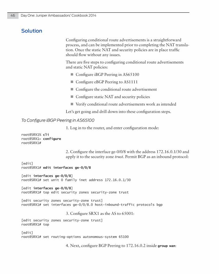
Solution
Configuring conditional route advertisements is a straightforward process, and can be implemented prior to completing the NAT transla-tion. Once the static NAT and security policies are in place traffic should flow without any issues.
There are five steps to configuring conditional route advertisements and static NAT policies:
� Configure iBGP Peering in AS65100
� Configure eBGP Peering to AS1111
� Configure the conditional route advertisement
� Configure static NAT and security policies
� Verify conditional route advertisements work as intended
Let’s get going and drill down into these configuration steps.
To Configure iBGP Peering in AS65100
1. Log in to the router, and enter configuration mode:
root@SRX1% cli root@SRX1> configureroot@SRX1#
2. Configure the interface ge-0/0/8 with the address 172.16.0.1/30 and apply it to the security zone trust. Permit BGP as an inbound protocol:
[edit]root@SRX1# edit interfaces ge-0/0/8
[edit interfaces ge-0/0/8]root@SRX1# set unit 0 family inet address 172.16.0.1/30
[edit interfaces ge-0/0/8]root@SRX1# top edit security zones security-zone trust
[edit security zones security-zone trust]root@SRX1# set interfaces ge-0/0/8.0 host-inbound-traffic protocols bgp
3. Configure SRX1 as the AS to 65001:
[edit security zones security-zone trust]root@SRX1# top
[edit]root@SRX1# set routing-options autonomous-system 65100
4. Next, configure BGP Peering to 172.16.0.2 inside group wan:

Recipe6:ConditionalRouteAdvertisingwithNATontheSRXSeries 47
[edit]root@SRX1# edit protocols bgp group wan
[edit protocols bgp group wan]root@SRX1# set peer-as 65100
[edit protocols bgp group wan]root@SRX1# set type internal
[edit protocols bgp group wan]root@SRX1# set neighbor 172.16.0.2
5. Jump to the top of the hierarchy and commit the configuration:
[edit protocols bgp group wan]root@SRX1# top
[edit]root@SRX1# commit and-quitconfiguration check succeedscommit completeExiting configuration mode
root@SRX1>
6. Verify that BGP peering is up, and the SRX is receiving the route 192.168.1.0/24 from its neighbor:
root@SRX1> show route protocol bgp
inet.0: 17 destinations, 17 routes (17 active, 0 holddown, 0 hidden)+ = Active Route, - = Last Active, * = Both
192.168.1.0/24 *[BGP/170] 11w1d 04:31:28, MED 1376000, localpref 100 AS path: ? > to 172.16.0.2 via ge-0/0/8.0root@SRX1>
To Configure eBGP Peering in AS1111
1. Configure interface ge-0/0/4 with the address 200.200.200.2/30 and apply it to the security zone untrust. Permit BGP as an inbound protocol:
root@SRX1> configureEntering Configuration Mode
root@SRX1# [edit]root@SRX1# edit interfaces ge-0/0/4
[edit interfaces ge-0/0/4]root@SRX1# set unit 0 family inet address 200.200.200.2/30

48 DayOne:JuniperAmbassadors’Cookbook2014
[edit interfaces ge-0/0/4]root@SRX1# top edit security zones security-zone untrust
[edit security zones security-zone untrust]root@SRX1# set interfaces ge-0/0/4.0 host-inbound-traffic protocols bgp
2. Next, configure BGP Peering to 200.200.200.1 inside group partner:
[edit security zones security-zone untrust]root@SRX1# top edit protocols bgp group partner
[edit protocols bgp group partner]root@SRX1# set peer-as 1111
[edit protocols bgp group parter]root@SRX1# set type external
[edit protocols bgp group partner]root@SRX1# set neighbor 200.200.200.1
3. Jump to the top of the hierarchy and commit the configuration:
[edit protocols bgp group wan]root@SRX1# top
[edit]root@SRX1# commitconfiguration check succeedscommit complete
root@SRX1#
To Configure the Conditional Route Advertisement
1. Now configure an export policy as conditional_route to advertise 1.1.1.0/24 and include a condition called check_route. Make sure to configure the policy to reject all other routes:
[edit]root@SRX1# edit policy-options policy-statement conditional_route
[edit policy-options policy-statement conditional_route]root@SRX1# set term 1 from route-filter 1.1.1.0/24 exact
[edit policy-options policy-statement conditional_route]root@SRX1# set term 1 from condition check_route
[edit policy-options policy-statement conditional_route]root@SRX1# set term 1 then accept
[edit policy-options policy-statement conditional_route]root@SRX1# set then reject

Recipe6:ConditionalRouteAdvertisingwithNATontheSRXSeries 49
2. Next, configure condition check_route. In this case the SRX will use route 192.168.1.0/24 to perform this check:
[edit policy-options policy-statement conditional_route]root@SRX1# top edit policy-options condition check_route
[edit policy-options condition check_route]root@SRX1# set if-route-exists 192.168.1.0/24
[edit policy-options condition check_route]root@SRX1# set if-route-exists table inet.0
3. Jump to the top of the hierarchy and apply the export policy to group partner:
[edit policy-options condition check_route]root@SRX1# top edit protocols bgp group partner
[edit protocols bgp group partner]root@SRX1# set export conditional_route
4. One more jump to the top of the hierarchy and configure a discard route to ensure that 1.1.1.0/24 is present in the routing table:
[edit policy-options condition check_route]root@SRX1# top
[edit]root@SRX1# set routing-options static route 1.1.1.0/24 discard
5. Finally, commit the configuration:
[edit]root@SRX1# commitconfiguration check succeedscommit complete
root@SRX1#
To Configure the Static NAT and Security Policies
1. Configure a static NAT policy to NAT 1.1.1.1/32 to 192.168.1.1/32 – don’t forget to include the proxy-arp settings:
[edit]root@SRX1# edit security nat static rule-set untrust
[edit security nat static rule-set untrust]root@SRX1# set from zone untrust
[edit security nat static rule-set untrust]root@SRX1# set rule app match destination-address 1.1.1.1/32
[edit security nat static rule-set untrust]root@SRX1# set rule app then static-nat prefix 192.168.1.1/32

50 DayOne:JuniperAmbassadors’Cookbook2014
[edit security nat static rule-set untrust]root@SRX1# top edit security nat proxy-arp interface ge-0/0/4.0
[edit security nat proxy-arp interface ge-0/0/4.0]root@SRX1# set address 1.1.1.1/32
2. Next, configure the address book entry for the server 192.168.1.1/32 in the trust zone:
[edit security nat proxy-arp interface ge-0/0/4.0]root@SRX1# top
[edit]root@SRX1# set security zones security-zone trust address-book address server-192.168.1.1/32 192.168.99.1/32
3. Now, add the policy to permit traffic inbound:
[edit]root@SRX1# top edit security policies from-zone untrust to-zone trust
[edit security policies from-zone untrust to-zone trust]root@SRX1# set policy allow-app match source-address any
[edit security policies from-zone untrust to-zone trust]root@SRX1# set policy allow-app match destination-address server-192.168.1.1/32
[edit security policies from-zone untrust to-zone trust]root@SRX1# set policy allow-app match application any
[edit security policies from-zone untrust to-zone trust]root@SRX1# set policy allow-app then permit
4. Jump to the top of the hierarchy and commit the configuration:
[edit security policies from-zone untrust to-zone trust]root@SRX1# top
[edit]root@SRX1# commit and-quitconfiguration check succeedscommit completeExiting configuration mode
root@SRX1>
To Verify Conditional Route Advertisements Work as Intended
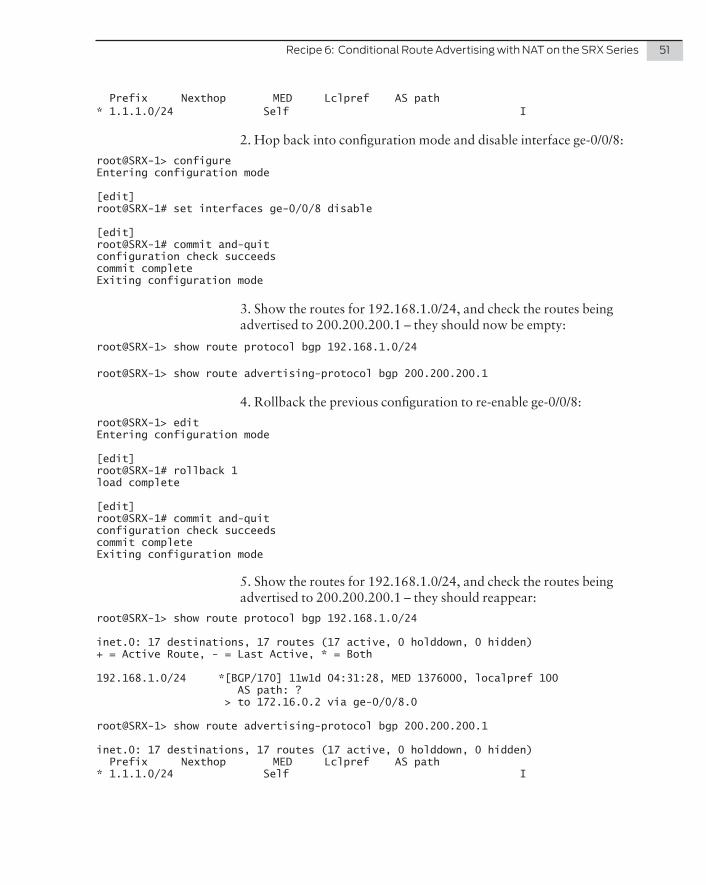
1. Show the routes advertised to BGP peer 200.200.200.1 and you should see 1.1.1.0/24 advertised:
root@SRX1> show route advertising-protocol bgp 200.200.200.1 inet.0: 17 destinations, 17 routes (17 active, 0 holddown, 0 hidden)
Recipe6:ConditionalRouteAdvertisingwithNATontheSRXSeries 51
Prefix Nexthop MED Lclpref AS path* 1.1.1.0/24 Self I
2. Hop back into configuration mode and disable interface ge-0/0/8:
root@SRX-1> configure Entering configuration mode
[edit]root@SRX-1# set interfaces ge-0/0/8 disable
[edit]root@SRX-1# commit and-quit configuration check succeedscommit completeExiting configuration mode
3. Show the routes for 192.168.1.0/24, and check the routes being advertised to 200.200.200.1 – they should now be empty:
root@SRX-1> show route protocol bgp 192.168.1.0/24
root@SRX-1> show route advertising-protocol bgp 200.200.200.1
4. Rollback the previous configuration to re-enable ge-0/0/8:
root@SRX-1> edit Entering configuration mode
[edit]root@SRX-1# rollback 1load complete
[edit]root@SRX-1# commit and-quit configuration check succeedscommit completeExiting configuration mode
5. Show the routes for 192.168.1.0/24, and check the routes being advertised to 200.200.200.1 – they should reappear:
root@SRX-1> show route protocol bgp 192.168.1.0/24
inet.0: 17 destinations, 17 routes (17 active, 0 holddown, 0 hidden)+ = Active Route, - = Last Active, * = Both
192.168.1.0/24 *[BGP/170] 11w1d 04:31:28, MED 1376000, localpref 100 AS path: ? > to 172.16.0.2 via ge-0/0/8.0
root@SRX-1> show route advertising-protocol bgp 200.200.200.1
inet.0: 17 destinations, 17 routes (17 active, 0 holddown, 0 hidden) Prefix Nexthop MED Lclpref AS path* 1.1.1.0/24 Self I

52 DayOne:JuniperAmbassadors’Cookbook2014
Discussion
In a typical Junos-based router, setting the discard route would usually drop all traffic in the 1.1.1.0/24 network, but here on the SRX flow-based Junos performs the route lookup. In Figure 6.2, the SRX will first NAT to the destination address of 192.168.1.1, and then perform the route lookup! Because of this the packet is treated as routable, and the SRX will forward the packet.
Screens Static Dest Route Zones Policy Static Source Services Session NAT NAT NAT NAT ALG
Screens TCP NAT Services ALG
Forwarding Lookup
YES YESNO
MatchSession?First Packet
Junos OS Flow2 Module
YES
Figure 6.2 Route Lookups are Performed After the Static NAT is Applied
References
Look for more information on configuring static NAT here: http://www.juniper.net/techpubs/en_US/junos12.1/topics/example/nat-security-static-single-address-translation-configuring.html
Configuring Conditional Installation of Prefixes in a Routing Table: http://www.juniper.net/techpubs/en_US/junos13.3/topics/example/conditional-prefix-installing-configuring.html

When it comes to routing protocols, most organizations prefer to utilize either OSPF or RIP, and some may even use EIGRP. But there is a fourth protocol option, too; it’s one that ISPs have been using for a number of years, known as IS-IS, or Intermediate System to Intermediate System.
IS-IS was originally developed to advertise routes for a protocol that was competing with TCP/IP, however, because of the way IS-IS was designed, it was easily able to adapt to advertise IPv4, and later IPv6, and can easily scale to a considerable size that some say could rival BGP. Because of the flexibility and scalability it offers, it makes good sense to know how to implement and support IS-IS. The purpose of this recipe is to show you how to implement a basic IS-IS network between two devices.
This recipe is perfect for the lab to get you familiar with the workings of IS-IS.
Problem
Networking professionals typically know how to configure OSPF and RIP, and most have had exposure to EIGRP, but the number of network professionals who know about IS-IS isn’t as large. This recipe uses a small topology shown in Figure 7.1.
Recipe 7
Basic IS-IS Implementation
by Martin Brown
54 DayOne:JuniperAmbassadors’Cookbook2014
30.0.0.0/24IS-IS10.0.0.0/24
SRX210 J2320
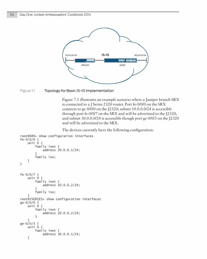
Figure 7.1 Topology for Basic IS-IS Implementation
Figure 7.1 illustrates an example scenario where a Juniper branch SRX is connected to a J Series 2320 router. Port fe-0/0/0 on the SRX connects to ge-0/0/0 on the J2320; subnet 10.0.0.0/24 is accessible through port fe-0/0/7 on the SRX and will be advertised to the J2320, and subnet 30.0.0.0/24 is accessible though port ge-0/0/3 on the J2320 and will be advertised to the SRX.
The devices currently have the following configuration:
root@SRX> show configuration interfacesfe-0/0/0 { unit 0 { family inet { address 20.0.0.1/24; } family iso; }}
fe-0/0/7 { unit 0 { family inet { address 10.0.0.2/24; } family iso; }root@JSERIES> show configuration interfacesge-0/0/0 { unit 0 { family inet { address 20.0.0.2/24; } }ge-0/0/3 { unit 0 { family inet { address 30.0.0.1/24; }

Recipe7:BasicIS-ISImplementation 55
Solution
The first step is to create a loopback interface on the devices. These interfaces need an IP address with a /32 prefix. In this instance we will give the SRX loopback interface an address of 192.168.1.1/32 and the J2320 will have an address of 192.168.1.2/32.
For the SRX:
set interfaces lo0.0 family inet address 192.168.1.1/32
And for the J2320:
set interfaces lo0.0 family inet address 192.168.1.2/32
Next, it’s important to understand that IS-IS does not use TCP/IP as the transport layer, but instead it uses a protocol called ISO. One major difference between ISO and TCP/IP is that ISO gives an address to the router as opposed to TCP/IP which has an address per interface.
The address for ISO is made up as follows:
49.0001.0001.0001.0001.00
AFI Area ID System ID n-selector
� AFI – Authority and Format Indicator. This identifies this device as a router and as such will always be 49.
� Area ID – Similar to IPv4 subnets. For IS-IS, all routers in the domain will use the same area ID.
� System ID – Similar to an IPv4 host address. Each router must have a unique number. This cannot be all 0’s but can be hexa-decimal.
� n-selector – Always set as 00.
NOTE This is just a very brief overview of the address format. Further information can easily be found from various sources on the Internet, including Juniper’s website.
Now assign this address to the loopback interface on each device as follows:
For the SRX:
set interfaces lo0.0 family iso address 49.0001.0001.0001.0001.00
For the J2320:
set interfaces lo0.0 family iso address 49.0001.0001.0001.0002.00

56 DayOne:JuniperAmbassadors’Cookbook2014
By adding the ISO address to the loopback interface, you have in fact given the router its unique address. The next step would be to tell which interfaces are to be included in the routing advertisements.
In our scenario, fe-0/0/7.0 on the SRX connects to subnet 10.0.0.0/24, and ge-0/0/3.0 on the J2320 is part of subnet 30.0.0.0/24. In addition, the interfaces that connect the two devices also need to be included, and fe-0/0/0.0 on the SRX is directly connected to ge-0/0/0.0 on the J series. These would be added as follows.
On the SRX:
set protocols isis interface fe-0/0/0.0set protocols isis interface fe-0/0/7.0set protocols isis interface lo0.0
On the J2320:
set protocols isis interface ge-0/0/0.0set protocols isis interface ge-0/0/3.0set protocols isis interface lo0.0
This still won’t be enough, however, as you have not told the devices to use the ISO protocol on the interfaces that are being advertised.
Okay, you’ve already done this on the loopback interface by adding the address, however you need to add this to fe-0/0/0.0 and fe-0/0/7.0 on the SRX and ge-0/0/0.0 and ge-0/0/3.0 on the J series.
On the SRX:
set interfaces fe-0/0/7 unit 0 family isoset interfaces fe-0/0/0 unit 0 family iso
On the J2320:
set interfaces ge-0/0/3 unit 0 family isoset interfaces ge-0/0/0 unit 0 family iso
Once you have committed the configuration, you can check whether IS-IS is running and on which interfaces. This is done as follows:
root@SRX> show isis interface IS-IS interface database:Interface L CirID Level 1 DR Level 2 DR L1/L2 Metricfe-0/0/0.0 3 0x2 SRX.02 SRX.02 10/10fe-0/0/7.0 3 0x1 SRX.00 SRX.00 10/10lo0.0 0 0x1 Passive Passive 0/0
root@JSERIES> show isis interface IS-IS interface database:Interface L CirID Level 1 DR Level 2 DR L1/L2 Metricge-0/0/0.0 3 0x1 SRX.02 SRX.02 10/10ge-0/0/3.0 3 0x1 JSERIES.00 JSERIES.00 10/10lo0.0 0 0x1 Passive Passive 0/0

Recipe7:BasicIS-ISImplementation 57
You can also check to see if the devices are neighbors or have formed adjacencies:
root@SRX> show isis adjacency Interface System L State Hold (secs) SNPAfe-0/0/0.0 JSERIES 1 Up 23 0:1b:c0:53:13:0fe-0/0/0.0 JSERIES 2 Up 21 0:1b:c0:53:13:0
root@JSERIES> show isis adjacency Interface System L State Hold (secs) SNPAge-0/0/0.0 SRX 1 Up 6 2c:21:72:27:76:0ge-0/0/0.0 SRX 2 Up 6 2c:21:72:27:76:0
You may have noticed Level 1 and Level 2 being mentioned in the output. IS-IS would use Level 2 routers for the backbone, similar to OSPF area 0 and Level 1 routers in the connected subnets, similar to OSPF areas, and you also have Level 1-2 routers, which are performing both roles. In this scenario you are staying with the defaults, which are Levels 1-2.
NOTE As this is a basic IS-IS implementation, it is a very brief overview of areas – there are plenty of resources describing IS-IS areas on Juniper’s website and in RFC 1195 and 5302.
Next you need to confirm that the routing updates are being ex-changed. You’ve assumed both devices are able to ping each other and as you have seen, the devices have formed an adjacency, therefore if you look at the route table on the devices, you should see not only the subnet being advertised, but the loopback interface of the opposing device too.
Let’s check:
root@SRX> show route protocol isis
inet.0: 12 destinations, 12 routes (12 active, 0 holddown, 0 hidden)+ = Active Route, - = Last Active, * = Both
30.0.0.0/24 *[IS-IS/15] 00:11:03, metric 20 > to 20.0.0.2 via fe-0/0/0.0192.168.1.2/32 *[IS-IS/15] 00:07:04, metric 10 > to 20.0.0.2 via fe-0/0/0.0
iso.0: 1 destinations, 1 routes (1 active, 0 holddown, 0 hidden)
root@JSERIES> show route protocol isis
inet.0: 14 destinations, 14 routes (14 active, 0 holddown, 0 hidden)+ = Active Route, - = Last Active, * = Both
10.0.0.0/24 *[IS-IS/15] 00:12:56, metric 20 > to 20.0.0.1 via ge-0/0/0.0

58 DayOne:JuniperAmbassadors’Cookbook2014
192.168.1.1/32 *[IS-IS/15] 00:09:04, metric 10 > to 20.0.0.1 via ge-0/0/0.0iso.0: 1 destinations, 1 routes (1 active, 0 holddown, 0 hidden)
Finally, issue a ping from the SRX to the subnet, accessible from ge-0/0/3.0 on the J2320, and you should receive a response, thereby confirming routes are being advertised both ways:
root@SRX> ping 30.0.0.1 PING 30.0.0.1 (30.0.0.1): 56 data bytes64 bytes from 30.0.0.1: icmp_seq=0 ttl=64 time=2.394 ms64 bytes from 30.0.0.1: icmp_seq=1 ttl=64 time=2.456 ms64 bytes from 30.0.0.1: icmp_seq=2 ttl=64 time=3.871 ms64 bytes from 30.0.0.1: icmp_seq=3 ttl=64 time=2.314 ms
References
Should you wish to find out more about IS-IS, try the following links: http://tools.ietf.org/html/rfc1195
http://tools.ietf.org/html/rfc5302
http://www.juniper.net/techpubs/en_US/junos13.3/topics/example/routing-protocol-is-is-security-configuring-cli.html

IS-IS is a powerful routing protocol that can scale to a consider-able size and allow for fast reconvergence, adapting quickly to route changes and additions. The modular nature of IS-IS also allows developers to easily add advertisements for additional routed protocols, as was done recently for IPv6. There is, as always, a downside, and in this case the downside is that not all devices support IS-IS.
Problem
It would be a perfect world if every network device spoke the same language and supported the same features. The brutal truth, however, is the world isn’t perfect and when network devices don’t support a common set of features it is our job as networking professionals to make them work together to achieve connectiv-ity.
This recipe guides you through a sceneraio where a Juniper branch SRX is connected to a J Series 2320 router, and the J2320 is in turn connected to an EX2200 Layer 3 switch as shown in Figure 8.1.
Recipe 8
Redistributing RIP into IS-IS
by Martin Brown
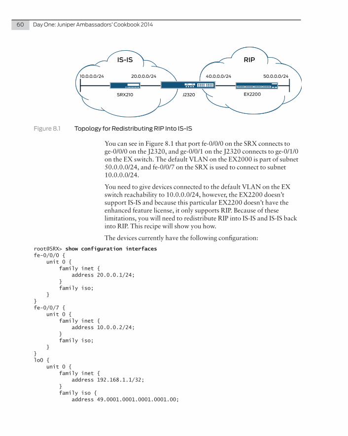
60 DayOne:JuniperAmbassadors’Cookbook2014
50.0.0.0/24
IS-IS
10.0.0.0/24
SRX210 J2320
40.0.0.0/2420.0.0.0/24
RIP
EX2200
Figure 8.1 Topology for Redistributing RIP Into IS-IS
You can see in Figure 8.1 that port fe-0/0/0 on the SRX connects to ge-0/0/0 on the J2320, and ge-0/0/1 on the J2320 connects to ge-0/1/0 on the EX switch. The default VLAN on the EX2000 is part of subnet 50.0.0.0/24, and fe-0/0/7 on the SRX is used to connect to subnet 10.0.0.0/24.
You need to give devices connected to the default VLAN on the EX switch reachability to 10.0.0.0/24, however, the EX2200 doesn’t support IS-IS and because this particular EX2200 doesn’t have the enhanced feature license, it only supports RIP. Because of these limitations, you will need to redistribute RIP into IS-IS and IS-IS back into RIP. This recipe will show you how.
The devices currently have the following configuration:
root@SRX> show configuration interfaces fe-0/0/0 { unit 0 { family inet { address 20.0.0.1/24; } family iso; }}fe-0/0/7 { unit 0 { family inet { address 10.0.0.2/24; } family iso; }} lo0 { unit 0 { family inet { address 192.168.1.1/32; } family iso { address 49.0001.0001.0001.0001.00;

Recipe8:RedistributingRIPintoIS-IS 61
} }}
root@SRX> show configuration protocols isis { interface fe-0/0/0.0; interface fe-0/0/7.0; interface lo0.0;}
root@JSERIES> show configuration interfaces ge-0/0/0 { unit 0 { family inet { address 20.0.0.2/24; } family iso; }}ge-0/0/1 { unit 0 { family inet { address 40.0.0.1/24; } }}lo0 { unit 0 { family inet { address 192.168.1.2/32; } family iso { address 49.0001.0001.0001.0002.00; } }}
root@JSERIES> show configuration protocols isis { interface ge-0/0/0.0; interface ge-0/0/3.0; interface lo0.0;}
root@EX-SWITCH> show configuration interfaces ge-0/1/0 { unit 0 { family inet { address 40.0.0.2/24; } }}

62 DayOne:JuniperAmbassadors’Cookbook2014
vlan { unit 0 { family inet { address 50.0.0.1/24; } }}
{master:0}root@EX-SWITCH> show configuration protocols rip { group RIP { export RIP; neighbor vlan.0; neighbor ge-0/1/0.0; }}
{master:0}root@EX-SWITCH> show configuration policy-options policy-statement RIP { term 1 { from protocol [ direct rip ]; then accept; }}
Solution
The first step is to add RIP to the J2320 and ensure it forms a neighbor-ship with the EX2200. RIP under Junos has a rather unique configura-tion requirement when compared to IS-IS, or OSPF, in that when adding RIP to Junos devices, a policy statement needs to be created to tell the router which routes to advertise to neighbors. So let’s create such a policy statement to include RIP and directly connected routes and tell RIP to use this statement. Give the policy statement the name of RIPADVERT and tell RIP to use this statement in addition to telling it which interface to use to send out RIP hello packets. This would be achieved as follows:
set policy-options policy-statement RIPADVERT term 1 from protocol ripset policy-options policy-statement RIPADVERT term 1 from protocol directset policy-options policy-statement RIPADVERT term 1 then accept
set protocol rip group RIP export RIPADVERTset protocol rip group RIP neighbor ge-0/0/1.0
NOTE Since the SRX already has IS-IS and the EX has RIP, you only need to add the configuration changes to the J Series router. There are no configuration changes to either the firewall or the switch in this recipe.

Recipe8:RedistributingRIPintoIS-IS 63
Once you have committed the configuration changes, a few simple checks can now be performed to verify neighborships and that the J Series is receiving routes from the EX switch:
root@JSERIES> show rip neighbor Local Source Destination Send Receive InNeighbor State Address Address Mode Mode Met-------- ----- ------- ----------- ---- ------- ---ge-0/0/1.0 Up 40.0.0.1 224.0.0.9 mcast both 1
root@JSERIES> show route protocol rip
inet.0: 13 destinations, 13 routes (13 active, 0 holddown, 0 hidden)+ = Active Route, - = Last Active, * = Both
0.0.0.0/0 *[RIP/100] 01:34:54, metric 3, tag 0 > to 40.0.0.2 via ge-0/0/1.050.0.0.0/24 *[RIP/100] 01:39:49, metric 2, tag 0 > to 40.0.0.2 via ge-0/0/1.0224.0.0.9/32 *[RIP/100] 01:56:13, metric 1 MultiRecv
iso.0: 1 destinations, 1 routes (1 active, 0 holddown, 0 hidden)
What is interesting here is that there is a default route pointing back to the EX2200, and this is not normal, because RIP does not add a default route automatically. This default route has in fact come from an ADSL router connected to the switch that is redistributing a default static route into RIP. Under normal circumstances, it would be good security practice to disconnect this ADSL router and put proper firewall protection in place, however, in this instance let’s keep this router in place and use it to test connectivity later.
Once you have verified that the router has formed a neighborship with the switch, the next step is to perform the redistribution itself, by using the exact same policy statements used to tell RIP which routes to advertise.
NOTE As IS-IS can scale considerably larger than RIP it may not be a good idea to redistribute IS-IS routes numbering in their hundreds into RIP. As this scenario uses a small IS-IS network, it is perfectly acceptable to redistribute in this instance.
In order to redistibute IS-IS into RIP, you need to tell the policy statement to include IS-IS updates also. You could, in theory, use the same term and just add IS-IS as a protocol option, however, in this case, you’ll create a new term called term 2 and use this to advertise IS-IS instead:
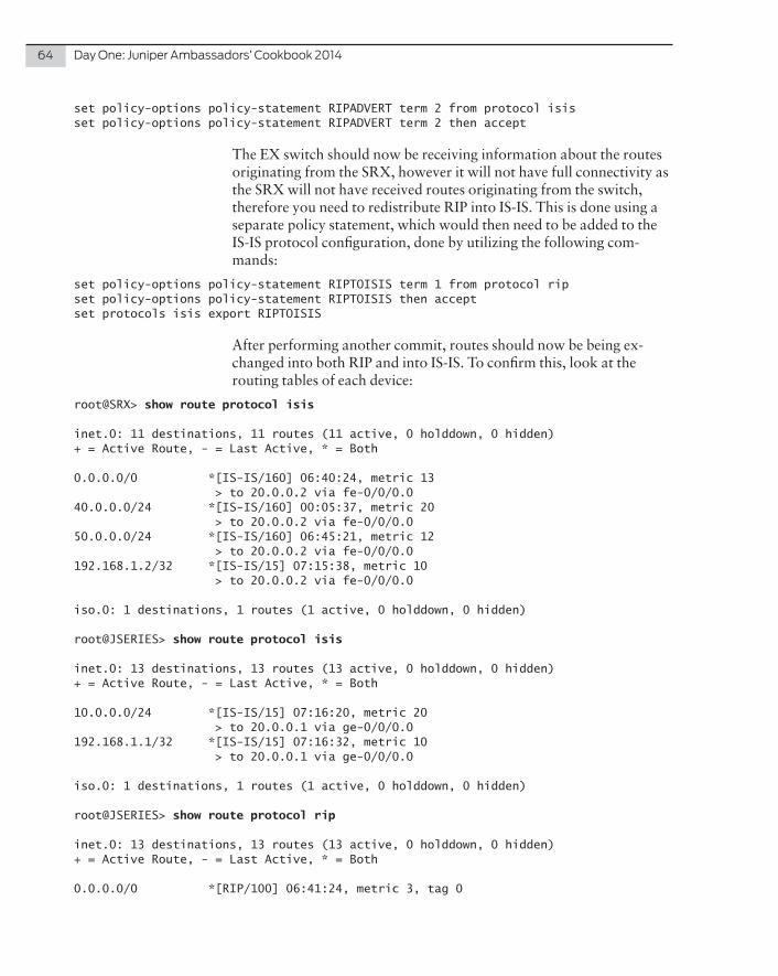
64 DayOne:JuniperAmbassadors’Cookbook2014
set policy-options policy-statement RIPADVERT term 2 from protocol isisset policy-options policy-statement RIPADVERT term 2 then accept
The EX switch should now be receiving information about the routes originating from the SRX, however it will not have full connectivity as the SRX will not have received routes originating from the switch, therefore you need to redistribute RIP into IS-IS. This is done using a separate policy statement, which would then need to be added to the IS-IS protocol configuration, done by utilizing the following com-mands:
set policy-options policy-statement RIPTOISIS term 1 from protocol ripset policy-options policy-statement RIPTOISIS then acceptset protocols isis export RIPTOISIS
After performing another commit, routes should now be being ex-changed into both RIP and into IS-IS. To confirm this, look at the routing tables of each device:
root@SRX> show route protocol isis
inet.0: 11 destinations, 11 routes (11 active, 0 holddown, 0 hidden)+ = Active Route, - = Last Active, * = Both
0.0.0.0/0 *[IS-IS/160] 06:40:24, metric 13 > to 20.0.0.2 via fe-0/0/0.040.0.0.0/24 *[IS-IS/160] 00:05:37, metric 20 > to 20.0.0.2 via fe-0/0/0.050.0.0.0/24 *[IS-IS/160] 06:45:21, metric 12 > to 20.0.0.2 via fe-0/0/0.0192.168.1.2/32 *[IS-IS/15] 07:15:38, metric 10 > to 20.0.0.2 via fe-0/0/0.0
iso.0: 1 destinations, 1 routes (1 active, 0 holddown, 0 hidden)
root@JSERIES> show route protocol isis
inet.0: 13 destinations, 13 routes (13 active, 0 holddown, 0 hidden)+ = Active Route, - = Last Active, * = Both
10.0.0.0/24 *[IS-IS/15] 07:16:20, metric 20 > to 20.0.0.1 via ge-0/0/0.0192.168.1.1/32 *[IS-IS/15] 07:16:32, metric 10 > to 20.0.0.1 via ge-0/0/0.0
iso.0: 1 destinations, 1 routes (1 active, 0 holddown, 0 hidden)
root@JSERIES> show route protocol rip
inet.0: 13 destinations, 13 routes (13 active, 0 holddown, 0 hidden)+ = Active Route, - = Last Active, * = Both
0.0.0.0/0 *[RIP/100] 06:41:24, metric 3, tag 0

Recipe8:RedistributingRIPintoIS-IS 65
> to 40.0.0.2 via ge-0/0/1.050.0.0.0/24 *[RIP/100] 06:46:21, metric 2, tag 0 > to 40.0.0.2 via ge-0/0/1.0
iso.0: 1 destinations, 1 routes (1 active, 0 holddown, 0 hidden)
{master:0}root@EX-SWITCH> show route protocol rip
inet.0: 12 destinations, 12 routes (12 active, 0 holddown, 0 hidden)+ = Active Route, - = Last Active, * = Both
0.0.0.0/0 *[RIP/100] 06:42:03, metric 2, tag 0 > to 50.0.0.2 via vlan.010.0.0.0/24 *[RIP/100] 07:16:54, metric 2, tag 0 > to 40.0.0.1 via ge-0/1/0.020.0.0.0/24 *[RIP/100] 07:16:54, metric 2, tag 0 > to 40.0.0.1 via ge-0/1/0.0192.168.1.1/32 *[RIP/100] 07:16:54, metric 2, tag 0 > to 40.0.0.1 via ge-0/1/0.0192.168.1.2/32 *[RIP/100] 07:16:54, metric 2, tag 0 > to 40.0.0.1 via ge-0/1/0.0
Finally, by issuing a ping from the SRX fe-0/0/7 interface to the subnet connected to the default VLAN on the EX switch, you should you have full connectivity both ways:
root@SRX> ping 50.0.0.1 source 10.0.0.2 PING 50.0.0.1 (50.0.0.1): 56 data bytes64 bytes from 50.0.0.1: icmp_seq=0 ttl=63 time=4.307 ms64 bytes from 50.0.0.1: icmp_seq=1 ttl=63 time=4.293 ms64 bytes from 50.0.0.1: icmp_seq=2 ttl=63 time=4.761 ms64 bytes from 50.0.0.1: icmp_seq=3 ttl=63 time=3.969 ms
As you saw in the routing tables, the EX switch has also picked up a default route from the ADSL router connected to it. This default route has been advertised back to the SRX, so in theory this means you should be able to ping to an external address. Let’s attempt to ping the Google DNS server:
root@SRX> ping 8.8.8.8 PING 8.8.8.8 (8.8.8.8): 56 data bytes64 bytes from 8.8.8.8: icmp_seq=0 ttl=41 time=38.721 ms64 bytes from 8.8.8.8: icmp_seq=1 ttl=41 time=38.167 ms64 bytes from 8.8.8.8: icmp_seq=2 ttl=41 time=39.134 ms64 bytes from 8.8.8.8: icmp_seq=3 ttl=41 time=37.117 ms
Everything is working and you have successfully redistributed IS-IS into RIP.

66 DayOne:JuniperAmbassadors’Cookbook2014
References
Should you wish to find out more about IS-IS, you may find the information in the following links very useful: http://www.juniper.net/techpubs/en_US/junos13.3/topics/example/routing-protocol-is-is-security-configuring-cli.html
http://www.juniper.net/techpubs/en_US/junos13.3/topics/topic-map/rip-basic.html
http://www.juniper.net/techpubs/en_US/junos13.3/topics/topic-map/isis-redistributing-routes.html

Multichassis Link Aggregation Group (MC-LAG) allows clients to perform redundancy and load-balancing across independent core chassis switches. This recipe will explain the configuration required to perform MC-LAG on Juniper MX Series.
Problem
In the topology illustrated in Figure 9.1, a client switch needs to be configured with a logical aggregate group (LAG) to two separate MX chassis. The MX Chassis will not be used in a Virtual Chassis configuration, meaning that each MX will have separate Control and Forwarding Planes.
Recipe 9
Configuring Active/Active MC-LAG on MX Series
by Clay Haynes

68 DayOne:JuniperAmbassadors’Cookbook2014
EX VC FPC0
EX VC FPC1
ICCP Address: 10.19.211.2/30
ICCP(ae20)
EX VC FPC2
EX VC FPC3
ICL(ae21)
ICCP Address: 10.19.211.1/30
vcp
vcp
MX MX Interface Switch MX MX Interface Switch
MX-01 xe-1/1/1 xe-0/1/0 MX-01 xe-7/1/1 xe-2/1/0
MX-01 xe-2/1/1 xe-1/1/0 MX-01 xe-8/1/1 xe-3/1/0
MX-02 xe-1/1/1 xe-0/1/2 MX-02 xe-7/1/1 xe-2/1/2
MX-02 xe-1/1/1 xe-1/1/2 MX-02 xe-8/1/1 xe-3/1/2
Figure 9.1 MC-LAG Topology
Solution
Since Virtual Chassis will not be configured on the MXs then the MXs must be configured as MC-LAG peers. The EX Virtual Chassis in the topology will be configured with a single LAG interface, and connect-ed to two xe interfaces on each MX chassis.
There are five steps to configure MC-LAG:
1. Configure the Interchassis Link-Protection Link (ICL-PL)
2. Configure Interchassis Link (ICL)
3. Configure an Integrated Routing and Bridging (IRB) L3 Interface with mac-synchronization
4. Configure the EX Virtual Chassis LAG
5. Verify the ICL-PL and ICL are operational
Let’s drill down into these five configuration steps.

Recipe9:ConfiguringActive/ActiveMC-LAGonMXSeries 69
1 . Configure the Interchassis Link-Protection Link
1. Log in to both routers, and enter configuration mode:
root@MX01% cli root@MX01> configureroot@MX01#
2. Since the ICL-PL is critical for the Inter-Chassis Control Protocol (ICCP) we will configure an aggregate link to provide multiple redundant paths. Configure ge-0/1/1, ge-0/1/2, ge-0/2/1, and ge-0/2/2 to be members of ae20 on both MXs:
[edit]root@MX01# set interfaces ge-0/1/1 gigether-options 802.3ad ae20
[edit]root@MX01# set interfaces ge-0/1/2 gigether-options 802.3ad ae20
[edit]root@MX01# set interfaces ge-0/2/1 gigether-options 802.3ad ae20
[edit]root@MX01# set interfaces ge-0/1/2 gigether-options 802.3ad ae20
3. Configure ae20 with the address 10.19.211.1/30 on MX01, and10.19.211.2/30 on MX02. Be sure to enable LACP on ae20:
MX01:[edit]root@MX01# set interfaces ae20 unit 0 family inet address 10.19.211.1/30
[edit]root@MX01# set interfaces ae20 aggregated-ether-options lacp
MX02:[edit]root@MX02# set interfaces ae20 unit 0 family inet address 10.19.211.2/30
[edit]root@MX02# set interfaces ae20 aggregated-ether-options lacp
4. From here, configure ICCP. On MX01 configure the local address to be 10.19.211.1, and the peer address to be 10.19.211.2 (MX02). On MX02, this is reversed, as the local address will be 10.19.211.2, and the peer address is 10.19.211.1 (MX01):
MX01:[edit]root@MX01# edit protocols iccp
[edit protocols iccp]root@MX01# set local-address 10.19.211.1

70 DayOne:JuniperAmbassadors’Cookbook2014
[edit protocols iccp]root@MX01# set peer 10.19.211.2
MX02:[edit]root@MX01# edit protocols iccp
[edit protocols iccp]root@MX01# set local-address 10.19.211.2
[edit protocols iccp]root@MX01# set peer 10.19.211.1
5. Additionally, on each respective peer, configure the redundancy-group-list and liveliness-detection for fast failover of the ICL-PL link on both MXs:
MX01:[edit protocols iccp]root@MX01# set peer 10.19.211.2 redundancy-group-list 1
[edit protocols iccp]root@MX01# set peer 10.19.211.2 liveliness-detection minimum-interval 150
[edit protocols iccp]root@MX01# set peer 10.19.211.2 liveliness-detection minimum-receive-interval 60
[edit protocols iccp]root@MX01# set peer 10.19.211.2 liveliness-detection multiplier 3
MX02:[edit protocols iccp]root@MX01# set peer 10.19.211.1 redundancy-group-list 1
[edit protocols iccp]root@MX01# set peer 10.19.211.1 liveliness-detection minimum-interval 150
[edit protocols iccp]root@MX01# set peer 10.19.211.1 liveliness-detection minimum-receive-interval 60
[edit protocols iccp]root@MX01# set peer 10.19.211.1 liveliness-detection multiplier 3
6. Head to the top of the configuration and commit on both MXs:
[edit protocols iccp]root@MX01# top
[edit]root@MX01# commit configuration check succeedscommit complete
root@MX01#
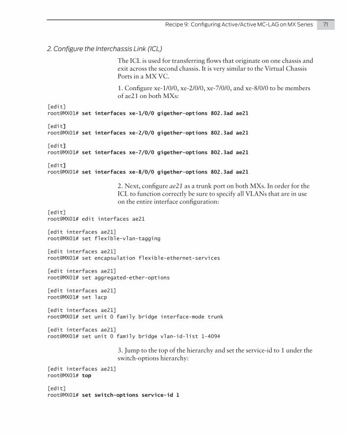
Recipe9:ConfiguringActive/ActiveMC-LAGonMXSeries 71
2 . Configure the Interchassis Link (ICL)
The ICL is used for transferring flows that originate on one chassis and exit across the second chassis. It is very similar to the Virtual Chassis Ports in a MX VC.
1. Configure xe-1/0/0, xe-2/0/0, xe-7/0/0, and xe-8/0/0 to be members of ae21 on both MXs:
[edit]root@MX01# set interfaces xe-1/0/0 gigether-options 802.3ad ae21
[edit]root@MX01# set interfaces xe-2/0/0 gigether-options 802.3ad ae21
[edit]root@MX01# set interfaces xe-7/0/0 gigether-options 802.3ad ae21
[edit]root@MX01# set interfaces xe-8/0/0 gigether-options 802.3ad ae21
2. Next, configure ae21 as a trunk port on both MXs. In order for the ICL to function correctly be sure to specify all VLANs that are in use on the entire interface configuration:
[edit]root@MX01# edit interfaces ae21
[edit interfaces ae21]root@MX01# set flexible-vlan-tagging
[edit interfaces ae21]root@MX01# set encapsulation flexible-ethernet-services
[edit interfaces ae21]root@MX01# set aggregated-ether-options
[edit interfaces ae21]root@MX01# set lacp
[edit interfaces ae21]root@MX01# set unit 0 family bridge interface-mode trunk
[edit interfaces ae21]root@MX01# set unit 0 family bridge vlan-id-list 1-4094
3. Jump to the top of the hierarchy and set the service-id to 1 under the switch-options hierarchy:
[edit interfaces ae21]root@MX01# top
[edit]root@MX01# set switch-options service-id 1

72 DayOne:JuniperAmbassadors’Cookbook2014
4. Finally, commit the configuration on both MXs:
[edit interfaces ae21]root@MX01# top
[edit]root@MX01# commitconfiguration check succeedscommit complete
root@MX01#
3 . Configure an L3 Integrated Routing and Bridging (IRB) Interface with MAC-Address Synchronization
An IRB interface is used to provide L3 capabilities through the MXs. MAC Address Synchronization allows both MXs to sync their IRB MAC Addresses so hosts can forward traffic to either MX and elimi-nate IP conflicts.
1. Create an IRB interface under the interfaces hierarchy on both MXs with the same 1.1.1.1/24 address:
[edit]root@MX01# set interfaces irb.1254 family inet address 1.1.1.1/24
2. Next, configure the bridge domain vlan_1254 under the bridge-domains hierarchy on both MXs. In this step be sure to also configure the routing interface and enable MAC-Address Synchronization:
[edit]root@MX01# edit bridge-domains vlan_1254
[edit bridge-domains vlan_1254]root@MX01# set vlan-id 1254
[edit bridge-domains vlan_1254]root@MX01# set mcae-mac-synchronize
[edit bridge-domains vlan_1254]root@MX01# set routing-interface irb.1254
3. Jump to the top of the hierarchy and commit the configuration on both MXs:
[edit]root@MX01# commitconfiguration check succeedscommit complete
root@MX01#

Recipe9:ConfiguringActive/ActiveMC-LAGonMXSeries 73
4 . Configure EX Virtual Chassis LAG
Before configuring the LAG, take a look at Table 9.1 – for each individual LAG created, some settings must match on both MXs, while other attributes are unique.
Table 9.1 MX and LAG Configuration
MX Configuration Lag Configuration
Aggregate Interface (aex) Match on both MXs Unique to each LAG
multi-chassis-protection Unique (Peer’s ICCP) Match
multi-chassis-protection interface ICL (ae21) Match
lacp system-id Match on both MXs Unique to each LAG
mc-ae mc-ae-id Match on both MXs Unique to each LAG
mc-ae redundancy-group Both must be set to 1 N/A
mc-ae chassis-id MX01 chassis-id is 0
MX02 chassis-id is 1
N/A
mc-ae mode Both must be set to active-active N/A
mc-ae status-control MX01 is active MX02 is standby
N/A
1. On both MXs set xe-1/1/1, xe-2/1/1, xe-7/1/1, and xe-8/1/1 to be members of ae0:
[edit]root@MX01# edit interfaces ae0
[edit interfaces ae0]root@MX01# set vlan-tagging
[edit interfaces ae0]root@MX01# set encapsulation flexible-ethernet-services
2. On both MXs edit interface ae0 and enable vlan-tagging as well as encapsulation flexible-ethernet-services:
[edit]root@MX01# edit interfaces ae0
[edit interfaces ae0]root@MX01# set vlan-tagging
[edit interfaces ae0]root@MX01# set encapsulation flexible-ethernet-services
3. Set the Multi-Chassis Protection on each LACP interface to the peer 3. address configured under protocols iccp:

74 DayOne:JuniperAmbassadors’Cookbook2014
MX01:[edit interfaces ae0]root@MX01# set multi-chassis-protection 10.19.211.2 interface ae21
MX02:[edit interfaces ae0]root@MX01# set multi-chassis-protection 10.19.211.1 interface ae21
4. Next, set a unique System ID for each LACP Bundle that matches on both MXs:
[edit interfaces ae0]root@MX01# set aggregated-ether-options lacp system-id 00:00:00:00:00:01
5. Now, edit the mc-ae hierarchy and configure the mc-ae-id, redundancy-group, mode, and status-control on both MXs:
MX01:[edit interfaces ae0]root@MX01# edit mc-ae
[edit interfaces ae0 mc-ae]root@MX01# set mc-ae-id 1
[edit interfaces ae0 mc-ae]root@MX01# set redundancy-group 1
[edit interfaces ae0 mc-ae]root@MX01# set chassis-id 0
[edit interfaces ae0 mc-ae]root@MX01# set mode active-active
[edit interfaces ae0 mc-ae]root@MX01# set status-control active
MX02:[edit interfaces ae0]root@MX01# edit mc-ae
[edit interfaces ae0 mc-ae]root@MX01# set mc-ae-id 1
[edit interfaces ae0 mc-ae]root@MX01# set redundancy-group 1
[edit interfaces ae0 mc-ae]root@MX01# set chassis-id 1
[edit interfaces ae0 mc-ae]root@MX01# set mode active-active
[edit interfaces ae0 mc-ae]root@MX01# set status-control standby

Recipe9:ConfiguringActive/ActiveMC-LAGonMXSeries 75
6. Configure ae0 as a trunk port on both MXs:
[edit interfaces ae0 mc-ae]root@MX01# up
[edit interfaces ae0]root@MX01# set unit 0 family bridge interface-mode trunk
[edit interfaces ae0]root@MX01# set unit 0 family bridge vlan-id-list 1-4094
7. Finally, commit the configuration on both MXs:
[edit]root@MX01# commit and-quitconfiguration check succeedscommit completeExiting configuration mode
root@MX01>
5 . Verify the ICL-PL and ICL are Operational
Show the ICCP protocol status on both MXs using the show iccp command:
MX01:root@MX01> show iccp Redundancy Group Information for peer 10.19.211.2 TCP Connection : Established Liveliness Detection : Up Redundancy Group ID Status 1 Up
Client Application: lacpd Redundancy Group IDs Joined: 1
Client Application: l2ald_iccpd_client Redundancy Group IDs Joined: 1
MX02:root@MX-02> show iccp
Redundancy Group Information for peer 10.19.211.1 TCP Connection : Established Liveliness Detection : Up Redundancy Group ID Status 1 Up
Client Application: lacpd Redundancy Group IDs Joined: 1
Client Application: l2ald_iccpd_client
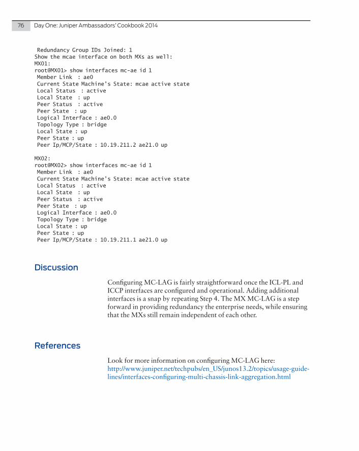
76 DayOne:JuniperAmbassadors’Cookbook2014
Redundancy Group IDs Joined: 1Show the mcae interface on both MXs as well:MX01:root@MX01> show interfaces mc-ae id 1 Member Link : ae0 Current State Machine's State: mcae active state Local Status : active Local State : up Peer Status : active Peer State : up Logical Interface : ae0.0 Topology Type : bridge Local State : up Peer State : up Peer Ip/MCP/State : 10.19.211.2 ae21.0 up
MX02:root@MX02> show interfaces mc-ae id 1 Member Link : ae0 Current State Machine's State: mcae active state Local Status : active Local State : up Peer Status : active Peer State : up Logical Interface : ae0.0 Topology Type : bridge Local State : up Peer State : up Peer Ip/MCP/State : 10.19.211.1 ae21.0 up
Discussion
Configuring MC-LAG is fairly straightforward once the ICL-PL and ICCP interfaces are configured and operational. Adding additional interfaces is a snap by repeating Step 4. The MX MC-LAG is a step forward in providing redundancy the enterprise needs, while ensuring that the MXs still remain independent of each other.
References
Look for more information on configuring MC-LAG here: http://www.juniper.net/techpubs/en_US/junos13.2/topics/usage-guide-lines/interfaces-configuring-multi-chassis-link-aggregation.html

ProblemIPsec VPN is the workhorse for enterprise site connections because it allows Internet connections to provide secure private transport. Both PanOS (Palo Alto Networks) and Junos support deploying route-based VPNs with tunnel interfaces for creating neighbor relationships, allowing a smooth integration of existing PanOS VPN infrastructure to the SRX Series. The problem is how build the interop tunnel.
SolutionThe basic steps of the interop configuration are:
Configure the SRX for Needed Services
Configure the PA200 for Needed Services
Configure tunnel interface Configure Security Zones
Configure LAN interface Configure WAN interface
Enable OSPF settings Configure LAN interface
Configure VPN parameters Configure tunnel interface
Configure security policies Enable OSPF settings
Configure VPN parameters
Configure security policies
NOTE Tested on a SRX100 using Junos 11.4r5.5 and a PA200 using PanOS 6.0.3.
Recipe 10
SRX Series OSPF Interop VPN with Palo Alto Networks
by Steve Puluka

78 DayOne:JuniperAmbassadors’Cookbook2014
trust
untrust e0/0 - 1.1.1.1/24
st0.010.0.0.1/24
SRX100
trust
untrust ethernet3 - 2.2.2.2/24
tun.110.0.0.2/24
PA-200
Tunnel InterfacesOSPF Area 0
Ethernet4 - 10.0.2.1/24 OSPF Area 0
Vlan.0 - 10.0.1.1/24 OSPF Area 0
Internet
Figure 10.1 The Topology of SRX Series OSPF Interop VPN with Palo Alto Networks Configuration
Configure the SRX Series
Step 1: Configure the SRX Tunnel Interface
Create the VPN tunnel interface and assign an IP range and address:
set interfaces st0 unit 0 family inet address 10.0.0.1/24set interfaces st0 unit 0 point-to-pointset security zones security-zone trust interfaces st0.0
Step 2: Configure the SRX LAN Interface
Create a LAN interface and then place it in the trust zone:
set interfaces fe-0/0/1 unit 0 family ethernet-switching set interfaces vlan unit 0 family inet address 10.0.1.1/24;set vlans vlan-trust vlan-id 2 set vlans vlan-trust l3-interface vlan.0set vlans vlan-trust interface fe-0/0/1.0set security zones security-zone trust host-inbound-traffic system-services allset security zones security-zone trust interfaces vlan.0

Recipe10:SRXSeriesOSPFInteropVPNwithPaloAltoNetworks 79
Step 3: Configure the SRX OSPF Parameters
Enable OSPF on the SRX and assign the local VLAN interface and the tunnel interface to OSPF area 0:
set protocols ospf area 0 interface vlan.0set protocols ospf area 0 interface st0.
Allow the host services for OSPF on the interfaces:
set security zones security-zone trust interfaces vlan.0 host-inbound-traffic protocols ospfset security zones security-zone trust interfaces st0.0 host-inbound-traffic protocols ospf
Configure vlan.0 to announce OSPF routes:
set protocols ospf area 0 interface vlan.0 passiveConfigure the OSPF router-idset routing-options router-id 10.0.1.1
Step 4: Configure the SRX VPN Parameters
Start by configuring the local gateway interface for the VPN. This will be the public IP address and interface from the local Internet service, and place these into the untrust zone in the primary routing instance.
Configure the Internet static IP address on the gateway interface:
set interfaces fe-0/0/0 unit 0 family inet address 1.1.1.1/24
Now set the default route for the local Internet service in the primary routing instance:
set routing-options static route 0.0.0.0/0 next-hop 1.1.1.254
Place the gateway interface into the untrust zone in the primary routing instance:
set security zones security-zone untrust interfaces fe-0/0/0.0
Now, allow management services on this interface for the VPN IKE connections. You can also allow management services as needed on this interface, but the IKE services are required to establish the VPN connection. Since this is an Internet-facing interface, you will not enable any other system services for now:
set security zones security-zone untrust host-inbound-traffic system-services ike
Next, configure the remote gateway IKE parameters for policy and a preshared key:
set security ike policy ike-policy1 mode mainset security ike policy ike-policy1 proposal-set standard

80 DayOne:JuniperAmbassadors’Cookbook2014
set security ike policy ike-policy1 pre-shared-key ascii-text "sharedsecret"
Now create the IPsec parameters for the VPN connection:
set security ipsec policy vpn-policy1 proposal-set standard
Follow these steps to create the route-based VPN using the tunnel interface you just created:
set security ike gateway ike-gate1 ike-policy ike-policy1set security ike gateway ike-gate1 address 2.2.2.2set security ike gateway ike-gate1 external-interface fe-0/0/0.0
Then use the existing policy to create the IPsec Phase 2 connection and tie this to the tunnel interface:
set security ipsec vpn ike-vpn1 ike gateway ike-gate1set security ipsec vpn ike-vpn1 ike ipsec-policy vpn-policy1set security ipsec vpn ike-vpn1 bind-interface st0.0set security ipsec vpn ike-vpn1 establish-tunnels immediately
Finally, set the VPN MTU to the most common value to prevent fragmentation issues of traffic across the tunnel:
set security flow tcp-mss ipsec-vpn mss 1350
Step 5: Configure the SRX Security Policy
Create a security policy to permit traffic across the VPN tunnel. In this case, both the tunnel interface and the local LAN interface are in the same security zone: trust. Thus we need a trust-to-trust policy to permit the communication. So create an open any-address to any-pro-tocol policy that can be adjusted as desired to more tightly control traffic:
set security policies from-zone trust to-zone trust policy allow-all match source-address any destination-address any application anyset security policies from-zone trust to-zone trust policy allow-all then permit
You can also place the tunnel interface into a separate zone to allow separation of policies for communications with the VPN, as opposed to the local zone.
Configure the PA200
Step 1: Configure the PA200 Zones Interface
Create the security zones for use by the interfaces. Menu: Net-work tab>Zones: Select add button:

Recipe10:SRXSeriesOSPFInteropVPNwithPaloAltoNetworks 81
Step 2: Configure the PA200 WAN Interface
Create address object for the WAN IP address. Menu: Objects>Addresses: Select add button:

82 DayOne:JuniperAmbassadors’Cookbook2014
Create the interface management policy to allow ping on the interfac-es. Menu: Network tab>Network Profiles>Interface Management: Se-lect new:
Create the WAN interface and assign an IP range and address. Menu: Network tab>Interfaces: Select Ethernet 1/3:
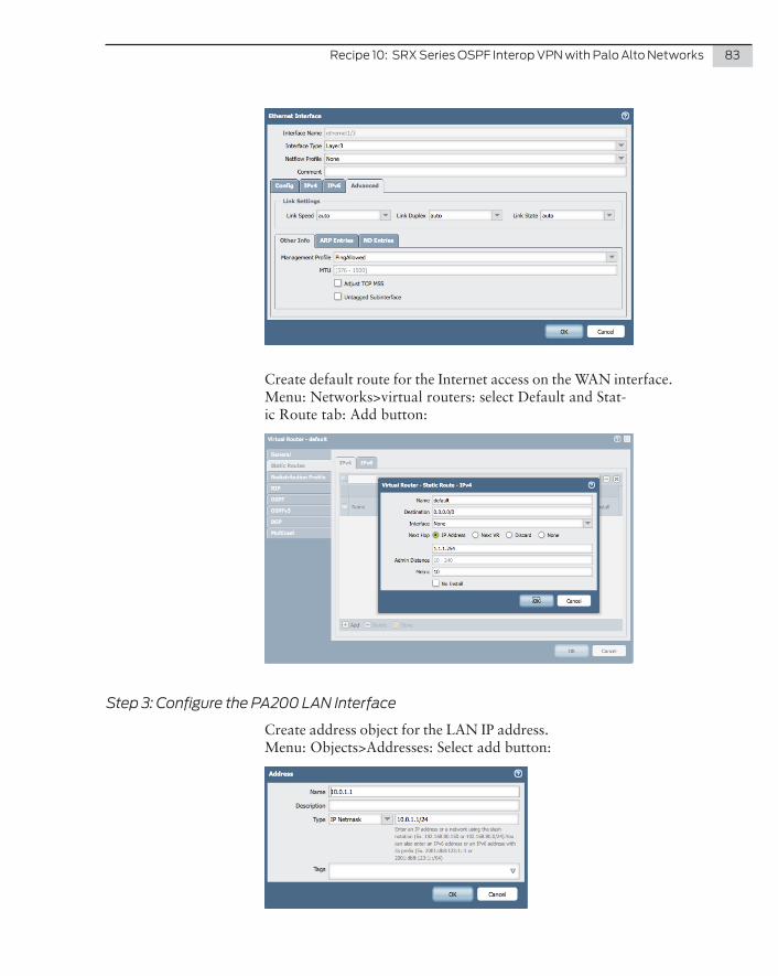
Recipe10:SRXSeriesOSPFInteropVPNwithPaloAltoNetworks 83
Create default route for the Internet access on the WAN interface. Menu: Networks>virtual routers: select Default and Stat-ic Route tab: Add button:
Step 3: Configure the PA200 LAN Interface
Create address object for the LAN IP address. Menu: Objects>Addresses: Select add button:

84 DayOne:JuniperAmbassadors’Cookbook2014
Create the LAN interface and assign an IP range and address. Menu: Network tab>Interfaces: Select Ethernet 1/4:
Step 4: Configure the PA200 Tunnel Interface
Create address object for the LAN IP address. Menu: Objects>Addresses: Select add button:
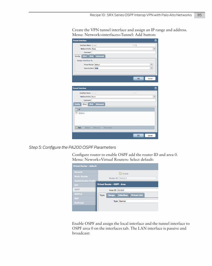
Recipe10:SRXSeriesOSPFInteropVPNwithPaloAltoNetworks 85
Create the VPN tunnel interface and assign an IP range and address. Menu: Network>interfaces>Tunnel: Add button:
Step 5: Configure the PA200 OSPF Parameters
Configure router to enable OSPF add the router ID and area 0. Menu: Nework>Virtual Routers: Select default:
Enable OSPF and assign the local interface and the tunnel interface to OSPF area 0 on the interfaces tab. The LAN interface is passive and broadcast:
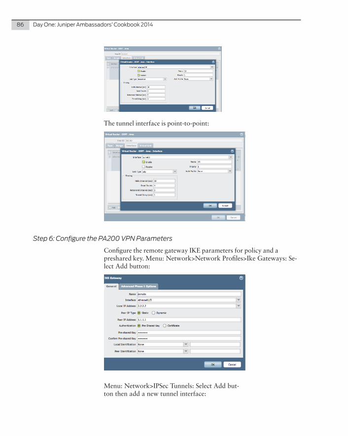
86 DayOne:JuniperAmbassadors’Cookbook2014
The tunnel interface is point-to-point:
Step 6: Configure the PA200 VPN Parameters
Configure the remote gateway IKE parameters for policy and a preshared key. Menu: Network>Network Profiles>Ike Gateways: Se-lect Add button:
Menu: Network>IPSec Tunnels: Select Add but-ton then add a new tunnel interface:

Recipe10:SRXSeriesOSPFInteropVPNwithPaloAltoNetworks 87
Step 7: Configure the PA200 Security Policy
Create a security policy to permit traffic across the VPN tunnel. In this case, both the tunnel interface and the local LAN interface are in the same security zone: trust. Thus we need a trust-to-trust policy to permit the communication. So create an open any-address to any-pro-tocol policy, as these can be adjusted as desired to more tightly control traffic.
You can also place the tunnel interface into a separate zone to allow a separation of policies for communications with the VPN as opposed to the local zone. Menu: Policies>Security: Select Add but-ton for new policy:

88 DayOne:JuniperAmbassadors’Cookbook2014
References
Understanding IPsec VPN: http://www.juniper.net/techpubs/en_US/junos11.4/information-prod-ucts/topic-collections/security/software-all/security/index.html?topic-54272.html
Configuring Route-based VPNs: http://www.juniper.net/techpubs/en_US/junos11.4/information-prod-ucts/topic-collections/security/software-all/security/index.html?topic-52842.html
OSPF:
http://kb.juniper.net/InfoCenter/index?page=content&id=KB16570
http://www.juniper.net/techpubs/en_US/junos11.4/information-prod-ucts/pathway-pages/config-guide-ospf/config-guide-ospf.html

Problem
IPsec VPN is the workhorse for enterprise site connections because it allows Internet connections to provide secure private transport. This recipe provides an interoperable configuration using a route-based VPN on the SRX Series to the policy-based VPN on the Sonicwall, allowing a smooth integration of existing SonicOS VPN infrastructure to SRX.
Solution
The basic steps of the interop configuration are:
Configure the SRX for needed services
Configure the TZ205 for needed services
Configure tunnel interface Configure LAN interface
Configure LAN interface Configure VPN parameters
Configure VPN parameters Configure security policies
Configure security policies
NOTE This recipe was tested on a SRX100 using Junos 11.4r5.5 and a TZ205 using SonicOS 5.0.5.10.
Recipe 11
SRX Series Interop VPN with Sonicwall by Steve Puluka

90 DayOne:JuniperAmbassadors’Cookbook2014
trust
untrust e0/0 - 1.1.1.1/24
st0.010.0.0.1/24
SRX100
trust
untrust WAN - 2.2.2.2/24
Sonicwall
LAN - 10.0.2.1/24
Vlan.0 - 10.0.1.1/24
Internet
Figure 11.1 The Topology of SRX Series Interop VPN with Sonicwall Configuration
Configure the SRX Series
Step 1: Configure the SRX Tunnel Interface
Create the VPN tunnel interface and assign an IP range and address:
set interfaces st0 unit 0 family inet address 10.0.0.1/24set interfaces st0 unit 0 point-to-pointset security zones security-zone trust interfaces st0.0
Create a static route to the tunnel interface for the remote site address:
set routing-options static route 10.0.2.0/24 next-hop st0.0
Step 2: Configure the SRX LAN Interface
Create a LAN interface and place it in the trust zone:
set interfaces fe-0/0/1 unit 0 family ethernet-switching set interfaces vlan unit 0 family inet address 10.0.1.1/24;set vlans vlan-trust vlan-id 2

Recipe11:SRXSeriesInteropVPNwithSonicwall 91
set vlans vlan-trust l3-interface vlan.0set vlans vlan-trust interface fe-0/0/1.0set security zones security-zone trust host-inbound-traffic system-services allset security zones security-zone trust interfaces vlan.0
Step 3: Configure the SRX VPN Parameters
Start by configuring the local gateway interface for the VPN. This will be the public IP address and interface from the local Internet service, and place these into the untrust zone in the primary routing instance.
Configure the Internet static IP address on the gateway interface:
set interfaces fe-0/0/0 unit 0 family inet address 1.1.1.1/24
Now set the default route for the local Internet service in the primary routing instance:
set routing-options static route 0.0.0.0/0 next-hop 1.1.1.254
Place the gateway interface into the untrust zone in the primary routing instance:
set security zones security-zone untrust interfaces fe-0/0/0.0
Now allow management services on this interface for the VPN IKE connections. You can also allow management services as needed on this interface, but the IKE services are required to establish the VPN connection. Since this is an Internet-facing interface, you will not enable any other system services for now:
set security zones security-zone untrust host-inbound-traffic system-services ike
Next, configure the remote gateway IKE parameters for policy and a preshared key:
set security ike policy ike-policy1 mode mainset security ike policy ike-policy1 proposal-set standardset security ike policy ike-policy1 pre-shared-key ascii-text "sharedsecret"
Now create the IPsec parameters for the VPN connection:
set security ipsec policy vpn-policy1 proposal-set standard
Follow these steps to create the route-based VPN using the tunnel interface you just created:
set security ike gateway ike-gate1 ike-policy ike-policy1set security ike gateway ike-gate1 address 2.2.2.2set security ike gateway ike-gate1 external-interface fe-0/0/0.0
Then use the existing policy to create the IPsec Phase 2 connection and tie this to the tunnel interface:

92 DayOne:JuniperAmbassadors’Cookbook2014
set security ipsec vpn ike-vpn1 ike gateway ike-gate1set security ipsec vpn ike-vpn1 ike ipsec-policy vpn-policy1set security ipsec vpn ike-vpn1 ike proxy-identity local 10.0.1.0/24 remote 10.0.2.0/24 service anyset security ipsec vpn ike-vpn1 bind-interface st0.0set security ipsec vpn ike-vpn1 establish-tunnels immediately
Finally, set the VPN MTU to the most common value to prevent frag-mentation issues of traffic across the tunnel:
set security flow tcp-mss ipsec-vpn mss 1350
Step 4: Configure the SRX Security PolicyCreate a security policy to permit traffic across the VPN tunnel. In this case, both the tunnel interface and the local LAN interface are in the same security zone: trust. Thus we need a trust-to-trust policy to permit the communication. So create an open any-address to any-protocol policy that can be adjusted as desired to more tightly control traffic.
You can also place the tunnel interface into a separate zone to allow a separation of policies for communications with the VPN as opposed to the local zone:
set security policies from-zone trust to-zone trust policy allow-all match source-address any destination-address any application anyset security policies from-zone trust to-zone trust policy allow-all then permit
You can also place the tunnel interface into a separate zone to allow a separation of policies for communications with the VPN as opposed to the local zone.

Recipe11:SRXSeriesInteropVPNwithSonicwall 93
Configure the TZ205
Step 1: Configure the TZ205 LAN Interfaces
By default the interface X0 is in the LAN zone with a port shield group including interfaces of X3 and X4. This means all three interfaces are available for local LAN devices.
You only need to change the IP address to the desired setting. Menu: Network>Interfaces: Select edit X0:
Step 2: Configure the TZ205 VPN Parameters
First you need to create the remote side network address object for use in the VPN creation. Menu: Network>Address Objects: Add button:

94 DayOne:JuniperAmbassadors’Cookbook2014
Next, use the Add VPN dialog box and the settings noted below. The first screen is where you select a “Policy Type” of Site-to-Site. Menu: VPN>Settings>VPN Policies: Add button:
The next tab is for the network parameters. This sets the proxy-id values for the VPN:

Recipe11:SRXSeriesInteropVPNwithSonicwall 95
For our configuration the default proposal parameters are acceptexyd:
On the advanced tab, remove the keep alive because you are using the same feature on the SRX side in establish tunnels immediately. If both sides are configured with this parameter it can cause issues with tunnel establishment because both sides are trying to be the initiator but not the responder for the IPsec communications.

96 DayOne:JuniperAmbassadors’Cookbook2014
Step 3: Configure the TZ205 Security Policy
In the SonicOS there is no need to create a security policy to permit traffic across the VPN tunnel. By default, a permit policy is created in both traffic directions when the VPN is created.
But if more control is desired check the box in the advanced tab of the VPN to suppress the automatic access rules. You can then go to the firewall section and manually create more specific policies for the tunnel traffic.
References
Understanding IPsec VPNs: http://www.juniper.net/techpubs/en_US/junos11.4/information-prod-ucts/topic-collections/security/software-all/security/index.html?topic-54272.html
Configuring Route-based VPNs: http://www.juniper.net/techpubs/en_US/junos11.4/information-prod-ucts/topic-collections/security/software-all/security/index.html?topic-52842.html
OSPF: http://kb.juniper.net/InfoCenter/index?page=content&id=KB16570
http://www.juniper.net/techpubs/en_US/junos11.4/information-prod-ucts/pathway-pages/config-guide-ospf/config-guide-ospf.html

Problem
IPsec VPN is the workhorse for enterprise site connections because it allows Internet connections to provide secure private transport. Both ScreenOS on the SSG device and Junos on the SRX Series support creating a route-based VPN with tunnel interfaces for creating neighbor relationships. This recipe pro-vides the steps to overcome the minor compatibility issues that arise when using OSPF across route-based VPNs between ScrenOS and Junos, allowing a smooth migration of existing ScreenOS VPN infrastructure to the SRX Series.
Solution
The basic steps of the interop configuration are:
Configure the SRX for needed services
Configure the SSG for needed services
Configure tunnel interface Configure tunnel interface
Configure LAN interface Configure LAN interface
Enable OSPF settings Enable OSPF settings
Configure VPN parameters Configure VPN parameters
Configure security policies Configure security policies
NOTE This recipe was tested on a SRX100 using Junos 11.4r5.5 and on SSG5 using ScreenOS 6.3r11.
Recipe 12
SRX Series Interop OSPF VPN with SSG
by Steve Puluka
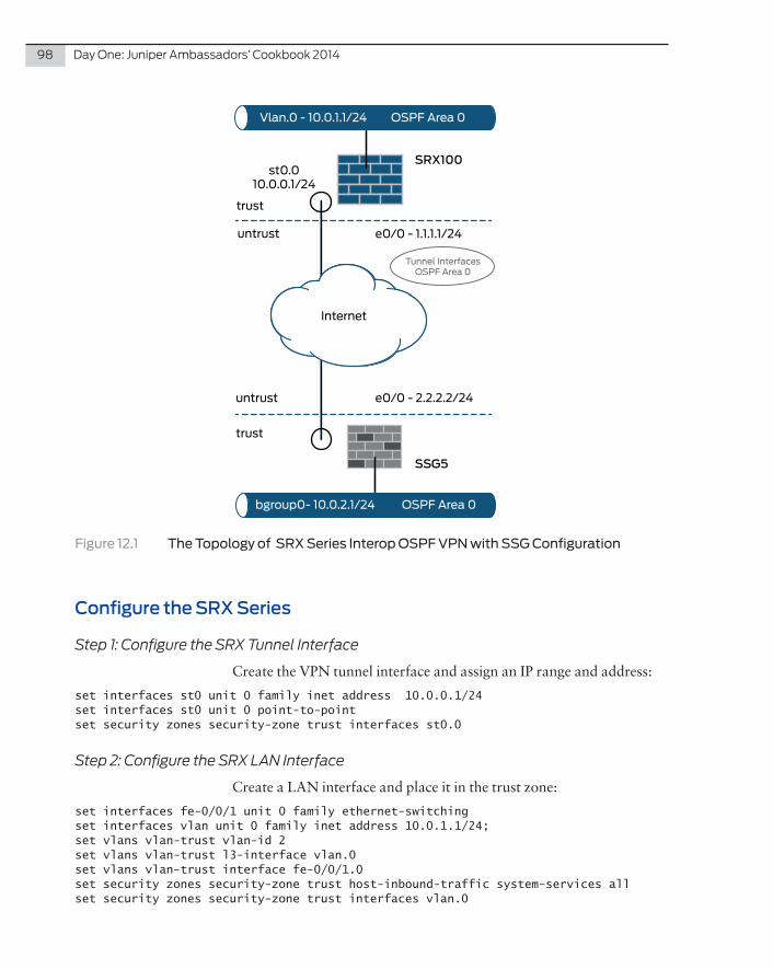
98 DayOne:JuniperAmbassadors’Cookbook2014
trust
untrust e0/0 - 1.1.1.1/24
st0.010.0.0.1/24
SRX100
trust
untrust e0/0 - 2.2.2.2/24
SSG5
bgroup0- 10.0.2.1/24 OSPF Area 0
Vlan.0 - 10.0.1.1/24 OSPF Area 0
Internet
Tunnel InterfacesOSPF Area 0
Figure 12.1 The Topology of SRX Series Interop OSPF VPN with SSG Configuration
Configure the SRX Series
Step 1: Configure the SRX Tunnel Interface
Create the VPN tunnel interface and assign an IP range and address:
set interfaces st0 unit 0 family inet address 10.0.0.1/24set interfaces st0 unit 0 point-to-pointset security zones security-zone trust interfaces st0.0
Step 2: Configure the SRX LAN Interface
Create a LAN interface and place it in the trust zone:
set interfaces fe-0/0/1 unit 0 family ethernet-switching set interfaces vlan unit 0 family inet address 10.0.1.1/24;set vlans vlan-trust vlan-id 2 set vlans vlan-trust l3-interface vlan.0set vlans vlan-trust interface fe-0/0/1.0set security zones security-zone trust host-inbound-traffic system-services allset security zones security-zone trust interfaces vlan.0
Recipe12:SRXSeriesInteropOSPFVPNwithSSG 99
Step 3: Configure the SRX OSPF Parameters
Enable OSPF on the SRX and assign the local VLAN interface and the tunnel interface to OSPF area 0:
set protocols ospf area 0 interface vlan.0set protocols ospf area 0 interface st0.0
Allow the host services for OSPF on the interfaces:
set security zones security-zone trust interfaces vlan.0 host-inbound-traffic protocols ospfset security zones security-zone trust interfaces st0.0 host-inbound-traffic protocols ospf
Configure vlan.0 to announce OSPF routes:
set protocols ospf area 0 interface vlan.0 passive
And then, configure the OSPF router-id:
set routing-options router-id 10.0.1.1
Step 4: Configure the SRX VPN Parameters
Start by configuring the local gateway interface for the VPN. This will be the public IP address and interface from the local Internet service, and place these into the untrust zone in the primary routing instance.
Configure the Internet static IP address on the gateway interface:
set interfaces fe-0/0/0 unit 0 family inet address 1.1.1.1/24
Now set the default route for the local Internet service in the primary routing instance:
set routing-options static route 0.0.0.0/0 next-hop 1.1.1.254
Place the gateway interface into the untrust zone in the primary routing instance:
set security zones security-zone untrust interfaces fe-0/0/0.0
Now allow management services on this interface for the VPN IKE connections. You can also allow management services as needed on this interface, but the IKE services are required to establish the VPN connection. Since this is an Internet-facing interface, you will not enable any other system services for now:
set security zones security-zone untrust host-inbound-traffic system-services ike
Next, configure the remote gateway IKE parameters for policy and a preshared key:

100 DayOne:JuniperAmbassadors’Cookbook2014
set security ike policy ike-policy1 mode mainset security ike policy ike-policy1 proposal-set standardset security ike policy ike-policy1 pre-shared-key ascii-text "sharedsecret"
Now create the IPsec parameters for the VPN connection:
set security ipsec policy vpn-policy1 proposal-set standard
Follow these steps to create the route-based VPN using the tunnel interface you just created:
set security ike gateway ike-gate1 ike-policy ike-policy1set security ike gateway ike-gate1 address 2.2.2.2set security ike gateway ike-gate1 external-interface fe-0/0/0.0
Now use the existing policy to create the IPsec Phase 2 connection and tie this to the tunnel interface:
set security ipsec vpn ike-vpn1 ike gateway ike-gate1set security ipsec vpn ike-vpn1 ike ipsec-policy vpn-policy1set security ipsec vpn ike-vpn1 bind-interface st0.0set security ipsec vpn ike-vpn1 establish-tunnels immediately
Finally, set the VPN MTU to the most common value to prevent fragmentation issues of traffic across the tunnel:
set security flow tcp-mss ipsec-vpn mss 1350
Step 5: Configure the SRX Security Policy
Create a security policy to permit traffic across the VPN tunnel. In this case both the tunnel interface and the local LAN interface are in the same security zone: trust. Thus we need a trust-to-trust policy to permit the communication. So create an open any-address to any-pro-tocol policy that can be adjusted as desired to more tightly control traffic.
You can also place the tunnel interface into a separate zone to allow a separation of policies for communications with the VPN as opposed to the local zone:
set security policies from-zone trust to-zone trust policy allow-all match source-address any destination-address any application anyset security policies from-zone trust to-zone trust policy allow-all then permit

Recipe12:SRXSeriesInteropOSPFVPNwithSSG 101
Configure the SSG Device
Step 1: Configure the SSG Tunnel Interface
Create the VPN tunnel interface and assign an IP range and address:
set interface tun.1 zone trustset interface tun.1 ip 10.0.0.2/24
Step 2: Configure the SSG LAN Interface
By default the bgroup0 interface is in the trust zone with member interfaces of 0/2 to 0/6. You only need to change the IP address to the desired setting:
set interface bgroup0 ip 10.0.2.1/24
Step 3: Configure the SSG OSPF Parameters
Configure the router for OSPF routes:
set vrouter trust-vr router-id 10.0.2.1set vrouter trust-vr protocol ospf enable
Enable OSPF and assign the local interface and the tunnel interface to OSPF area 0:
set interface bgroup0 protocol ospf area 0set interface bgroup0 protocol ospf passiveset interface bgroup0 protocol ospf enableset interface tun.1 protocol ospf area 0set interface tun.1 protocol ospf link-type p2pset interface tun.1 protocol ospf enable
Configure the interface to ignore MTU errors when establishing an OSPF neighbor relationship – this is required for compatibility and interop with the SRX. Without this setting the neighbor relationships will start to negotiate but will never fully form:
set interface tun.1 protocol ospf ignore-mtu
Step 4: Configure the SSG VPN Parameters
Start by configuring the local gateway interface for the VPN. This will be the public IP address and interface from the local internet service. By default ethernet0/0 is already in the untrust zone in the trust-vr.
Configure the Internet static IP address on the gateway interface:
set interface ethernet0/0 ip 2.2.2.2/24

102 DayOne:JuniperAmbassadors’Cookbook2014
Now set the default route for the local Internet service in the primary routing instance:
set route 0.0.0.0/0 interface ethernet0/0 gateway 2.2.2.254
Next, configure the remote gateway IKE parameters for policy and a preshared key:
set ike gateway ike-policy1 address 1.1.1.1 outgoing-interface eth0/0 preshare sharedsecret sec-level standard
Then create the IPsec Phase 2 connection and tie this to the tunnel interface:
set vpn ike-vpn1 gateway ike-policy1 sec-level standardset vpn ike-vpn1 bind interface tun.1
Configure the SSG Security Policy
There is no need to create a security policy to permit traffic across the VPN tunnel on the SSG with ScreenOS. By default, traffic within a zone is permitted. Because the tunnel interface and the local bgroup0 are both in the trust zone, no policy is required.
You can also place the tunnel interface into a separate zone to allow separate policies for communications with the VPN as opposed to the local zone.
References
Understanding IPsec VPNs: http://www.juniper.net/techpubs/en_US/junos11.4/information-prod-ucts/topic-collections/security/software-all/security/index.html?topic-54272.html
Configuring Route-based VPNs: http://www.juniper.net/techpubs/en_US/junos11.4/information-prod-ucts/topic-collections/security/software-all/security/index.html?topic-52842.html
OSPF: http://kb.juniper.net/InfoCenter/index?page=content&id=KB16570
http://www.juniper.net/techpubs/en_US/junos11.4/information-prod-ucts/pathway-pages/config-guide-ospf/config-guide-ospf.html

This recipe provides you with a guideline for configuring port mirroring on a Juniper router – especially the MX Series 3D router. The recipe is split into three sections: the first two sections focus on the local port mirroring features for Layer 3 (inet) and Layer 2 (bridge) traffic (MPLS mirroring is currently only sup-ported on the PTX platform), and the last section offers configu-ration examples to send the “mirrored” traffic to a remote probe.
Problem
How to mirror traffic when there are two bidirectional flows?
Solution
Figure 13.1 shows you the simple network of this recipe,which involves four MX routers and three probes. Let’s focus on the R2 router whose physical interfaces (xe-0/0/2 and xe-11/0/2) support two types of family:
� unit 0: family inet – vlan-id 10
� unit 100: family bridge – vlan-id 100
There are two bidirectional flows with a fixed rate sent through R2. The aim is to mirror traffic, both the routed (Flow 1) and the bridged (Flow 2) traffic. The mirrored traffic on R2 should be sent to the two local probes (Probe 1 and 2) and to the remote Probe 3.
Recipe 13
Port Mirroring
by David Roy

104 DayOne:JuniperAmbassadors’Cookbook2014
Router / Interface Family Vlan-ID IPv4 Address
R2 / xe-0/0/2.0 inet 10 172.16.20.5/30
R2 / xe-0/0/2.100 bridge 100 NA
R2 / xe-11/0/2.0 inet 10 172.16.20.1/30
R2 / xe-11/0/2.100 bridge 100 NA
R2 / ae0.0 inet NA 172.16.20.9/30
R2 / lo0.0 inet NA 172.16.16.1/32
R2 / irb.100 inet NA 192.168.36.1/24
R4 /lo0.0 inet NA 172.16.16.2/32
Probe 1172.16.22.2/24
Probe 2172.16.23.2/24
Probe 3172.16.24.2/24
ge-2/0/9
ae0
xe-11/0/2.100
xe-0/0/2.0
xe-0/0/2.100
xe-11/0/2.0
ge-2/0/6.100 ge-2/0/7
R1 R2 R3
R4
Flow 2
Flow 1
Flow Type Rate (pps)
Flow 1 UDP 10000
Flow 2 TCP 20000
Figure 13.1 Port Mirroring Network Diagram
InitialConfigurationforR2
The R2 router is configured as followed:
interfaces { xe-0/0/2 { description "To_R3"; vlan-tagging; encapsulation flexible-ethernet-services; unit 0 { vlan-id 10; family inet { address 172.16.20.5/30; } family mpls; } unit 100 { encapsulation vlan-bridge; vlan-id 100; family bridge;
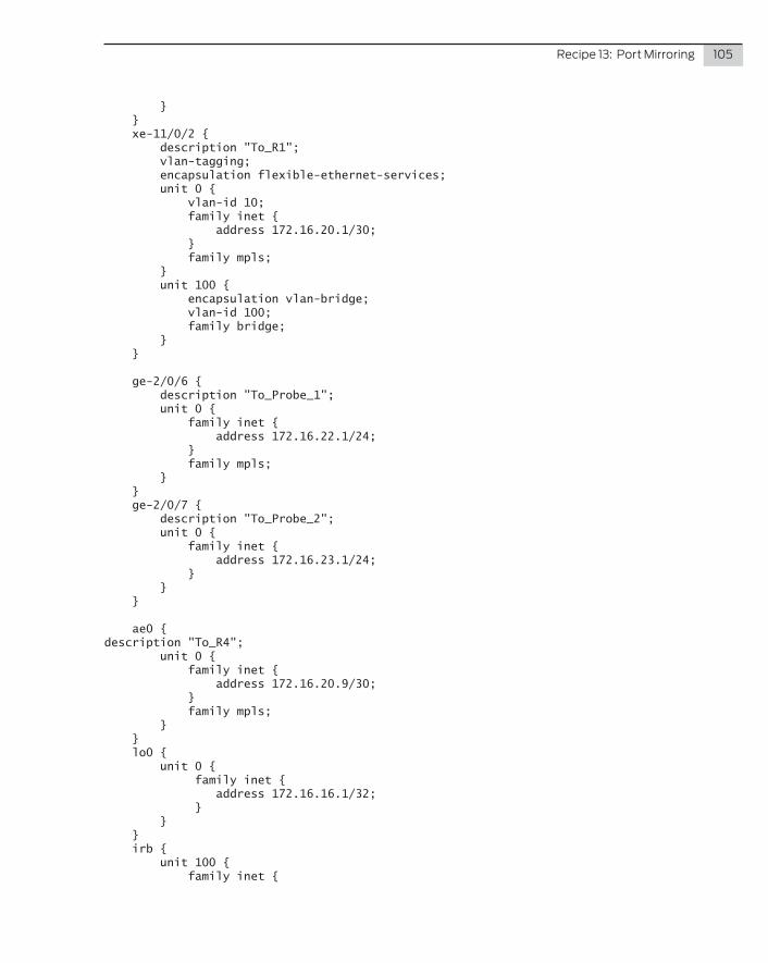
Recipe13:PortMirroring 105
} } xe-11/0/2 { description "To_R1"; vlan-tagging; encapsulation flexible-ethernet-services; unit 0 { vlan-id 10; family inet { address 172.16.20.1/30; } family mpls; } unit 100 { encapsulation vlan-bridge; vlan-id 100; family bridge; } }
ge-2/0/6 { description "To_Probe_1"; unit 0 { family inet { address 172.16.22.1/24; } family mpls; } } ge-2/0/7 { description "To_Probe_2"; unit 0 { family inet { address 172.16.23.1/24; } } }
ae0 {description "To_R4"; unit 0 { family inet { address 172.16.20.9/30; } family mpls; } } lo0 { unit 0 { family inet { address 172.16.16.1/32; } } } irb { unit 100 { family inet {

106 DayOne:JuniperAmbassadors’Cookbook2014
address 192.168.36.1/24; } } }}
bridge-domains { mydommain { vlan-id 100; interface xe-11/0/2.100; interface xe-0/0/2.100; routing-interface irb.100; }}
Now check the rates on xe-0/0/2 and xe-11/0/2. You can see the bidirectional 30kpps global traffic (inet + bridge):
droydavi@ncdib102> show interfaces xe-0/0/2 | match "Physical|rate"Physical interface: xe-0/0/2, Enabled, Physical link is Up Input rate : 126482992 bps (30000 pps) Output rate : 126483520 bps (30000 pps)
droydavi@ncdib102> show interfaces xe-11/0/2 | match "Physical|rate"Physical interface: xe-11/0/2, Enabled, Physical link is Up Input rate : 126479296 bps (30000 pps) Output rate : 126475072 bps (30000 pps)
Layer3LocalMirroring
Let’s start to configure R2’s port mirroring to capture the Flow 1 packets and forward them to local Probes 1 and 2. The mirroring feature is performed at a hardware level on the MPC linecard. There is no limitation regarding the mirrored packet rate as long as there is enough PFE / Fabric bandwidth. For traffic sampling, Junos supports multiple instances of port mirroring. In our case you need only to configure one instance. The mirroring instance is called MY_MIRROR and it’s configured at the forwarding options level in the Junos hierar-chy. As you’ll notice, the “instance name” is also specified at the chassis level on which MPC you want to capture traffic. In our case, you have to mirror traffic in both directions, either on xe-11/0/2 or xe-0/0/2. Let’s choose the xe-11/0/2 interface.
IMPORTANT In case of LAG interface where child links are spread over several linecards, do not forget to apply the port mirroring instance on the different MPCs (that participate with the LAG).
Now, let’s have a view of the configuration:
chassis { fpc 11 {

Recipe13:PortMirroring 107
port-mirror-instance MY_MIRROR; }}
forwarding-options { port-mirroring { mirror-once; instance { MY_MIRROR { input { rate 1; } family inet { output { next-hop-group GROUP_1; } } } } }}
As you can see, you mirror every packet (rate = 1). The mirror-once knob is sometimes needed when you want to mirror traffic in both directions and it avoids having duplicate packets on the destination mirroring interface.
Let’s have a look at the output statement under “family inet” level. “Output” means on which destination(s) the router has to send the mirrored packets.
Remember the aim is to send mirrored traffic toward two probes. When you have only one local probe connected, you can easily specify the destination interface under the output statement like this:
family inet { output { interface ge-0/0/6.0 { next-hop 172.16.22.2; } }}
Here, you sent the mirrored traffic to ge-2/0/6.0 interface. On non-point-to-point interfaces you must specify the next-hop address to allow the ARP resolution. Without the next-hop configuration the port mirroring will still remain down. If the probe is not configured to reply to the ARP request you also need to configure a static ARP entry with the MAC address of the probe or a fake MAC in case of the probe working in promiscuous mode:
ge-2/0/6 { unit 0 { family inet { address 172.16.22.1/24 { arp 172.16.22.2 mac 00:00:00:11:22:33;

108 DayOne:JuniperAmbassadors’Cookbook2014
} } }}
This is not our case as Probe 1 and Probe 2 can reply to ARP requests, therefore static ARP entries are unnecessary. Moreover, as the require-ment is to send mirrored traffic toward the two probes, use the next-hop-group feature under the output level. Next-hop-group is also defined at the forwarding-options level. You can also define under this statement several destination interfaces. Let’s have a look at the GROUP_1 next-hop-group configuration:
forwarding-options { next-hop-group GROUP_1 { group-type inet; interface ge-2/0/6.0 { next-hop 172.16.22.2; } interface ge-2/0/7.0 { next-hop 172.16.23.2; } }}
You can see that the two destination interfaces and their associated next-hop are well defined. Moreover, don’t forget to specify the type of next-hop to use: here it was “inet”. It’s time to check the status of your port mirroring configuration. To do that use this CLI command:
user@R2> show forwarding-options port-mirroringInstance Name: MY_MIRROR Instance Id: 2 Input parameters: Rate : 1 Run-length : 0 Maximum-packet-length : 0 Output parameters: Family State Destination Next-hop inet up GROUP_1
As expected port mirroring instance is UP. Currently there is no traffic mirrored. Actually, you need to specify which traffic you want to mirror via a Firewall Filter and apply it on a specific interface and a specific direction. The Flow 1 is a UDP stream, so our firewall filter is quite simple. You just have to specify the port-mirroring-instance action for which traffic you want to mirror:
firewall { family inet { filter MIRROR { term 1 { from { protocol udp; } then {
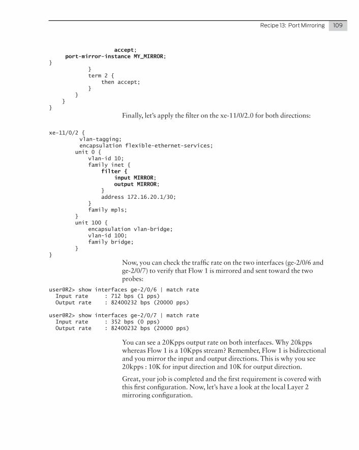
Recipe13:PortMirroring 109
accept; port-mirror-instance MY_MIRROR;} } term 2 { then accept; } } }}
Finally, let’s apply the filter on the xe-11/0/2.0 for both directions:
xe-11/0/2 { vlan-tagging; encapsulation flexible-ethernet-services; unit 0 { vlan-id 10; family inet { filter { input MIRROR; output MIRROR; } address 172.16.20.1/30; } family mpls; } unit 100 { encapsulation vlan-bridge; vlan-id 100; family bridge; }}
Now, you can check the traffic rate on the two interfaces (ge-2/0/6 and ge-2/0/7) to verify that Flow 1 is mirrored and sent toward the two probes:
user@R2> show interfaces ge-2/0/6 | match rate Input rate : 712 bps (1 pps) Output rate : 82400232 bps (20000 pps)
user@R2> show interfaces ge-2/0/7 | match rate Input rate : 352 bps (0 pps) Output rate : 82400232 bps (20000 pps)
You can see a 20Kpps output rate on both interfaces. Why 20kpps whereas Flow 1 is a 10Kpps stream? Remember, Flow 1 is bidirectional and you mirror the input and output directions. This is why you see 20kpps : 10K for input direction and 10K for output direction.
Great, your job is completed and the first requirement is covered with this first configuration. Now, let’s have a look at the local Layer 2 mirroring configuration.
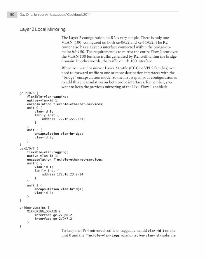
110 DayOne:JuniperAmbassadors’Cookbook2014
Layer2LocalMirroring
The Layer 2 configuration on R2 is very simple. There is only one VLAN (100) configured on both xe-0/0/2 and xe-11/0/2. The R2 router also has a Layer 3 interface connected within the bridge-do-main: irb.100. The requirement is to mirror the entire Flow 2 sent over the VLAN 100 but also traffic generated by R2 itself within the bridge domain. In other words, the traffic on irb.100 interface.
When you want to mirror Layer 2 traffic (CCC or VPLS families) you need to forward traffic to one or more destination interfaces with the “bridge” encapsulation mode. So the first step in your configuration is to add this encapsulation on both probe interfaces. Remember, you want to keep the previous mirroring of the IPv4 Flow 1 enabled:
ge-2/0/6 { flexible-vlan-tagging; native-vlan-id 1; encapsulation flexible-ethernet-services; unit 0 { vlan-id 1; family inet { address 172.16.22.2/24; } } unit 2 { encapsulation vlan-bridge; vlan-id 2; }}ge-2/0/7 { flexible-vlan-tagging; native-vlan-id 1; encapsulation flexible-ethernet-services; unit 0 { vlan-id 1; family inet { address 172.16.23.2/24; } } unit 2 { encapsulation vlan-bridge; vlan-id 2; }}
bridge-domains { MIRRORING_DOMAIN { interface ge-2/0/6.2; interface ge-2/0/7.2; }}
To keep the IPv4 mirrored traffic untagged, you add vlan-id 1 on the unit 0 and the flexible-vlan-tagging and native-vlan-id knobs are

Recipe13:PortMirroring 111
used to complete the task. Then you just have to add a new unit, here unit 2, and configure the vlan-bridge encapsulation on it. Finally, add the two bridged sub-interfaces within a dedicated bridge-domain to avoid commit failure.
Great! Your two probe interfaces are ready to forward Layer 2 mir-rored traffic. Let’s now add the Layer 2 port mirroring configuration: also known as the VPLS family under the port mirroring statement (family vpls includes VPLS and bridge encapsulations):
forwarding-options { port-mirroring { mirror-once; instance { MY_MIRROR { input { rate 1; } family inet { output { next-hop-group GROUP_1; } } family vpls { output { next-hop-group GROUP_2; } } } } } next-hop-group GROUP_1 { group-type inet; interface ge-2/0/6.0 { next-hop 172.16.22.2; } interface ge-2/0/7.0 { next-hop 172.16.23.2; } } next-hop-group GROUP_2 { group-type layer-2; interface ge-2/0/6.2; interface ge-2/0/7.2; }}
For the “inet” traffic a next-hop-group is used to include the two probes as the destination. In this case the next-hop-group is a Layer 2 type. Next-hop configuration is not allowed for this type, but actually it’s not necessary. Indeed, here you want to mirror Layer 2 frames, so R2 captures and directly forwards Ethernet Frames.
Let’s have a look at the port mirroring status:
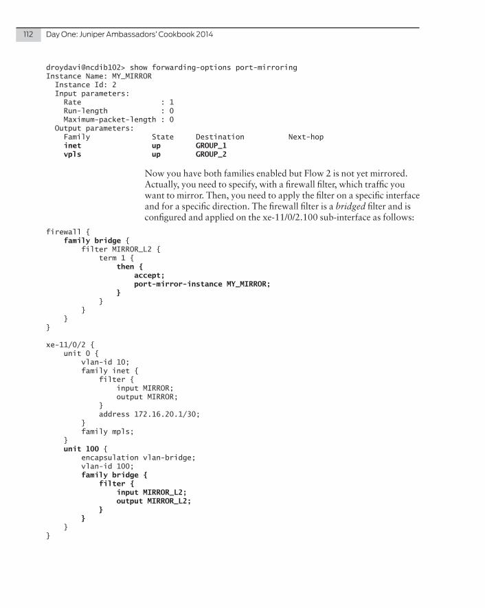
112 DayOne:JuniperAmbassadors’Cookbook2014
droydavi@ncdib102> show forwarding-options port-mirroringInstance Name: MY_MIRROR Instance Id: 2 Input parameters: Rate : 1 Run-length : 0 Maximum-packet-length : 0 Output parameters: Family State Destination Next-hop inet up GROUP_1 vpls up GROUP_2
Now you have both families enabled but Flow 2 is not yet mirrored. Actually, you need to specify, with a firewall filter, which traffic you want to mirror. Then, you need to apply the filter on a specific interface and for a specific direction. The firewall filter is a bridged filter and is configured and applied on the xe-11/0/2.100 sub-interface as follows:
firewall { family bridge { filter MIRROR_L2 { term 1 { then { accept; port-mirror-instance MY_MIRROR; } } } }}
xe-11/0/2 { unit 0 { vlan-id 10; family inet { filter { input MIRROR; output MIRROR; } address 172.16.20.1/30; } family mpls; } unit 100 { encapsulation vlan-bridge; vlan-id 100; family bridge { filter { input MIRROR_L2; output MIRROR_L2; } } }}
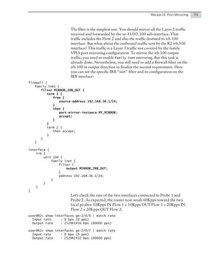
Recipe13:PortMirroring 113
The filter is the simplest one. You should mirror all the Layer 2 traffic received and forwarded by the xe-11/0/2.100 sub-interface. That traffic includes the Flow 2 and also the traffic destined to irb.100 interface. But what about the outbound traffic sent by the R2 irb.100 interface? This traffic is a Layer 3 traffic not covered by the family VPLS port mirroring configuration. To mirror the irb.100 output traffic, you need to enable family inet mirroring. But this task is already done. Nevertheless, you still need to add a firewall filter on the irb.100 in output direction to finalize the second requirement. Here you can see the specific IRB “inet” filter and its configuration on the IRB interface:
firewall { family inet { filter MIRROR_IRB_OUT { term 1 { from { source-address 192.168.36.1/24; } then { port-mirror-instance MY_MIRROR; accept; } } term 2 { then accept; } } }
interface { irb { unit 100 { family inet { filter { output MIRROR_IRB_OUT; } address 192.168.36.1/24; } } }}
Let’s check the rate of the two interfaces connected to Probe 1 and Probe 2. As expected, the router now sends 60Kpps toward the two local probes: 10Kpps IN Flow 1 + 10Kpps OUT Flow 1 + 20Kpps IN Flow 2 + 20Kpps OUT Flow 2:
user@R2> show interfaces ge-2/0/6 | match rate Input rate : 0 bps (0 pps) Output rate : 252961456 bps (60000 pps)
user@R2> show interfaces ge-2/0/7 | match rate Input rate : 0 bps (0 pps) Output rate : 252962432 bps (60000 pps)

114 DayOne:JuniperAmbassadors’Cookbook2014
RemoteMirroring
You have successly completed the first two requirements of this recipe. The last configuration step should allow the remote Probe 3 to receive a copy of the Layer 2 and Layer 3 mirrored traffic. To do that, tunnels are used between R2 and R4 router, which is directly connected to Probe 3. Two types of tunnels will be used:
� GRE tunnel: to convey Layer 3 traffic
� L2circuit: to convey Layer 2 traffic
The first configuration is the activation of tunnel service knob on both the R2 and R4 routers in order to have available tunnel interfaces.
NOTE On MPC linecard on this configuration has no effect.
You can choose an arbitrary MPC – on R2 and R4 the MPC is in slot 0:
chassis { fpc 0 { pic 0 { tunnel-services { bandwidth 10g; } } }}
Now, let’s start the configuration of the GRE tunnel. Use the lo0 addresses of R2 and R4 as tunnel end points. Also assign a private IP address on the GRE tunnel logical interface. Here’s the configuration of the GRE interface on R2:
interfaces { gr-0/0/0 { unit 0 { tunnel { source 172.16.16.1; destination 172.16.16.2; } family inet { address 172.16.30.1/30; } } }}
The configuration of the GRE interface on R4 is the following:
interfaces { gr-0/0/0 { unit 0 { tunnel { source 172.16.16.2; destination 172.16.16.1;

Recipe13:PortMirroring 115
} family inet { address 172.16.30.2/30; } } }}
Now, try to ping R4’s GRE interface from R2:
user@R2> ping 172.16.30.2 source 172.16.30.1PING 172.16.30.2 (172.16.30.2): 56 data bytes64 bytes from 172.16.30.2: icmp_seq=0 ttl=64 time=0.877 ms64 bytes from 172.16.30.2: icmp_seq=1 ttl=64 time=0.813 ms
Great! Remember R4 will receive IPv4 routed traffic on its GRE interface. After GRE decap. the mirrored traffic will be routed by the global routing table. To avoid the traffic injected back to the network, the best practice is to place the GRE interface of the remote router (R4) within a dedicated routing instance. Then you can also add the routed interface to the Probe 3 in the routing instance and finally add a static default route toward Probe 3.
Here is Probe 3’s interface and routing instance configuration on R4:
interfaces { ge-2/0/9 { flexible-vlan-tagging; native-vlan-id 1; encapsulation flexible-ethernet-services; unit 0 { vlan-id 1; family inet { address 172.16.24.1/24; } } }}routing-instances { MIRRORING_VR { instance-type virtual-router; interface ge-2/0/9.0; interface gr-0/0/0.0; routing-options { static { route 0.0.0.0/0 next-hop 172.16.24.2; } } }}
Let’s finalize the configuration by adding the GRE interface on R2 as a destination within the next-hop-group GROUP_1:
forwarding-options { next-hop-group GROUP_1 { group-type inet;

116 DayOne:JuniperAmbassadors’Cookbook2014
interface gr-0/0/0.0 { next-hop 172.16.30.2; } interface ge-2/0/6.0 { next-hop 172.16.21.6; } interface ge-2/0/7.0 { next-hop 172.16.21.2; } }}
Now, check traffic statistics of the R4 GRE interfaces. You’ll notice the GRE interface receives the IPv4 mirrored traffic well (2x 10Kpps):
user@R4> show interfaces gr-0/0/0 | match rate Input rate : 82402376 bps (20000 pps) Output rate : 0 bps (0 pps)
Then check that this traffic is well decap. and routed (in the routing instance) to the Probe 3 interface (the default route):
user@R4> show interfaces ge-2/0/9 | match rate Input rate : 0 bps (0 pps) Output rate : 82403455 bps (20000 pps)
Great! Move back to R2 and start the configuration of an lt interface. The two units of the lt interface will be used like this:
� unit 0 is the local destination sub-interface of the Layer 2 mir-rored traffic. This sub-interface will be added in the next-hop-group GROUP_2. The encapsulation of the unit 0 is set to VLAN-bridge.
� unit 1 is the CCC sub-interface, which will be remotely connect-ed via a L2circuit to a CCC unit of the ge-2/0/9 (Probe 3 inter-face’s) on R4.
Here is the configuration of the lt interface of R2. Don’t forget to add also the unit 0 in the local bridge domain to avoid commit failure:
interfaces { lt-0/0/0 { unit 0 { encapsulation vlan-bridge; vlan-id 513; peer-unit 1; } unit 1 { encapsulation vlan-ccc; vlan-id 513; peer-unit 0; } }}

Recipe13:PortMirroring 117
bridge-domains { MIRRORING_DOMAIN { interface ge-2/0/6.2; interface ge-2/0/7.2; interface lt-0/0/0.0; }}
Now, also add a CCC sub-interface on ge-2/0/9 R4 interfaces. Also, add this interface in a local bridge-domain to avoid commit failure:
interfaces { ge-2/0/9 { flexible-vlan-tagging; native-vlan-id 1; encapsulation flexible-ethernet-services; unit 0 { vlan-id 1; family inet { address 172.16.21.9/30; } } unit 2 { encapsulation vlan-ccc; vlan-id 513; } }}
bridge-domains { MIRRORING_DOMAIN { interface ge-2/0/9.2; }}
After that you can start the configuration of the L2circuit on R2 and R4 router. On R2:
protocols { ldp { interface all; } l2circuit { neighbor 172.16.16.2 { interface lt-0/0/0.1 { virtual-circuit-id 513; } } }}
On R4:
protocols { ldp { interface all; } l2circuit {

118 DayOne:JuniperAmbassadors’Cookbook2014
neighbor 172.16.16.1 { interface ge-2/0/9.2 { virtual-circuit-id 513; } } }}
Check your work and validate that the pseudowire is operational:
user@R2> show l2circuit connectionsLayer-2 Circuit Connections:
[...] Neighbor: 172.16.16.1 Interface Type St Time last up # Up trans ge-2/0/9.2(vc 513) rmt Up Aug 26 11:47:22 2014 1 Remote PE: 172.16.16.1, Negotiated control-word: Yes (Null) Incoming label: 307328, Outgoing label: 322176 Negotiated PW status TLV: No Local interface: ge-2/0/9.2, Status: Up, Encapsulation: VLAN
To finish this recipe let’s add the unit 0 of the R2. lt interfaces within the next-hop-group GROUP_2 to start sending Layer 2 mirrored traffic within the pseudowire:
forwarding-options { next-hop-group GROUP_2 { group-type layer-2; interface lt-0/0/0.0; interface ge-2/0/6.2; interface ge-2/0/7.2; }}
Let’s make a last check to validate that Probe 3 receives all R2 mirrored traffic:
user@R4> show interfaces ge-2/0/9 | match rate Input rate : 0 bps (0 pps) Output rate : 255522520 bps (60000 pps)
As expected the Probe 3 now receives 60Kpps coming from both tunnels: 10Kpps IN Flow 1 + 10Kpps OUT Flow 1 + 20Kpps IN Flow 2 + 20Kpps OUT Flow 2. This recipe’s requirements are proven: the three probes receive the Layer 2 and Layer 3 mirrored traffic.

Juniper recently added multiple proxy-ID support called traffic selectors in Junos 12.1. It makes configuring route-based VPNs a lot easier when setting up the security associations (SA) needed between peers.
Problem
Previously, there was no way to define having multiple proxy-ID support like the equipment of other vendors when setting up an IPsec VPN on an SRX. This sometimes made setting up a VPN on an SRX a little more challenging, but not impossible.
With the release of the 12.1X46 line of the Junos OS earlier this year, Juniper added support for this feature which essentially removes any type of lingering incompatibility with setting up an IPsec VPN tunnel no matter what hardware device is on the other end.
NOTE This feature is only available in Junos 12.1X46 and higher for the SRX. Currently you can only use it on route-based VPNs.
Solution
Using traffic selectors helps with the compatibility and robustness of your VPN tunnel. For example, in a route-based VPN you will typically have static route statements in your configuration directing the traffic through a certain tunnel interface (st0.x). By using traffic selectors to match up your SAs, the SRX automati-cally injects the route into the routing table for the VPN for each traffic selector you have configured.
Recipe 14
Configuring Multiple Proxy-IDs on an SRX IPsec VPN
by Scott Ware

120 DayOne:JuniperAmbassadors’Cookbook2014
NOTE The configurations of the security policies needed to permit/deny traffic are left out of this recipe.
Juniper makes this proxy-ID support really easy to implement. Let’s start with the basic setup for our VPN tunnel. First, configure IKE (Phase 1) with the following settings:
[edit security ike] proposal Site-A { authentication-method pre-shared-keys; dh-group group2; authentication-algorithm sha1; encryption-algorithm 3des-cbc; lifetime-seconds 86400;} policy Site-A { mode main; proposals Site-A; pre-shared-key ascii-text "juniper123";} gateway Site-A { ike-policy Site-A; address 100.1.1.50; no-nat-traversal; external-interface reth1.0;}
Now configure IPsec (Phase 2) with the following settings:
[edit security ipsec] proposal Site-A { protocol esp; authentication-algorithm hmac-sha1-96; encryption-algorithm 3des-cbc; lifetime-seconds 3600;} policy Site-A { proposals Site-A;} vpn Site-A { bind-interface st0.1; ike { gateway Site-A; idle-time 60; no-anti-replay; ipsec-policy Site-A; install-interval 0; } establish-tunnels immediately;}
The new traffic selector setting resides under the edit security ipsec vpn vpn-name hierarchy. The syntax for configuring a traffic-selector is as follows:

Recipe14:ConfiguringMultipleProxy-IDsonanSRXIPsecVPN 121
traffic-selector traffic-selector-name { local-ip ip-address/netmask; remote-ip ip-address/netmask; }
NOTE The traffic-selector-name must be no longer than 32 characters, and can contain the following special characters: _ (underscore), - (hy-phen), or no spaces.
You will need a traffic selector for every traffic (SA) pair. So let’s assume you have the following networks defined for both ends of the VPN tunnel:
Local Site Remote Site (Site-A)
192.168.4.5/32 172.16.1.0/24
10.5.5.0/23 172.16.4.0/23
10.5.10.0/24
Given the above information, six (6) traffic-selectors will need to be defined. Once you configure these, your edit security ipsec vpn Site-A configuration should resemble the following:
[edit security ipsec] vpn Site-A { bind-interface st0.1; ike { gateway Site-A; idle-time 60; no-anti-replay; ipsec-policy Site-A; install-interval 0; } traffic-selector TS1 { local-ip 192.168.4.5/32; remote-ip 172.16.1.0/24; } traffic-selector TS2 { local-ip 192.168.4.5/32; remote-ip 172.16.4.0/23; } traffic-selector TS3 { local-ip 10.5.5.0/23; remote-ip 172.16.1.0/24; } traffic-selector TS4 { local-ip 10.5.5.0/23; remote-ip 172.16.4.0/23; } traffic-selector TS5 { local-ip 10.5.10.0/24; remote-ip 172.16.1.0/24;

122 DayOne:JuniperAmbassadors’Cookbook2014
} traffic-selector TS6 { local-ip 10.5.10.0/24; remote-ip 172.16.4.0/23; } establish-tunnels immediately;}
NOTE If you are using NAT, then your local-ip option within your traffic-selector needs to be the IP address that the remote end is targeting. For more on how the SRX processes traffic flows, visit the following URL: http://kb.juniper.net/InfoCenter/index?page=content&id=KB16110
As you can see, the configuration of traffic selectors is really quite simple and can make setting up your IPsec VPNs much easier.
References
To find out more about traffic selectors and using them in IPsec VPNs, visit the following resources: http://www.juniper.net/techpubs/en_US/junos12.1x46/topics/concept/ipsec-vpn-traffic-selector-understanding.html
http://www.juniper.net/techpubs/en_US/junos12.1x46/topics/refer-ence/configuration-statement/traffic-selector-edit-security.html

Problem
A common network administrator’s task is to apply network changes at particular times and dates. Junos allows you to schedule and apply changes using configuration groups.
Solution
Configuration groups are a Junos methodolgy for creating general configuration blocks (think of templates) from one place of the device’s configuration and applying them into another place. The archetypal usage is changing the MTU on all interfaces: you can create a group with a MTU value and then apply it to all inter-faces with one command. And starting with Junos 11.3, you can use configuration groups to apply changes based on time, allow-ing for scheduling of any configuration changes.
Let’s look at an example where you have OSPF configured on the device with two GE interfaces participating:
Recipe 15
Scheduling Configuration Changes with Apply-groups
by Petr Klimaj

124 DayOne:JuniperAmbassadors’Cookbook2014
lab@srxE-1# show protocols ospf area 0.0.0.0 { interface ge-0/0/1.0; interface ge-0/0/2.0 { metric 10; } interface lo0.0;}
Routing to remote hosts (such as 10.0.0.2) now goes via the ge-0/0/1 interface due to its smaller metric (default OSPF metric for a GE interface is 1):
lab@srxE-1> show route 10.0.0.2
inet.0: 9 destinations, 9 routes (9 active, 0 holddown, 0 hidden)+ = Active Route, - = Last Active, * = Both
10.0.0.2/32 *[OSPF/10] 00:00:31, metric 1 > to 10.1.0.222 via ge-0/0/1.0
Let’s assume you want to transition traffic to the ge-0/0/2 interface (by increasing the metric of ge-0/0/1) at some time, for example, from 12:10 to 12:20 am. This is how you can do it.
First, create a configuration group and use the when option to specify the time:
[edit]lab@srxE-1# set groups MOVE-TRAFFIC when time 12:10 to 12:20
[edit]lab@srxE-1# set groups MOVE-TRAFFIC protocols ospf area 0.0.0.0 interface ge-0/0/1.0 metric 100
Apply it in the configuration, and commit (commit operation not shown):
[edit]lab@srxE-1# set apply-groups MOVE-TRAFFIC
Let’s check how it works with the following set of commands (note that the set cli timestamp operational mode command is used to make Junos write the time of execution of any command):
lab@srxE-1> set cli timestamp Jun 23 12:08:56CLI timestamp set to: %b %d %T
lab@srxE-1> show route 10.0.0.2

Recipe15:SchedulingConfigurationChangeswithApply-groups 125
Jun 23 12:09:06
inet.0: 9 destinations, 9 routes (9 active, 0 holddown, 0 hidden)+ = Active Route, - = Last Active, * = Both
10.0.0.2/32 *[OSPF/10] 00:00:41, metric 1 > to 10.1.0.222 via ge-0/0/1.0
lab@srxE-1> show configuration protocols ospf | display inheritance Jun 23 12:10:34area 0.0.0.0 { interface ge-0/0/1.0 { ## ## '100' was inherited from group 'MOVE-TRAFFIC' ## metric 100; } interface ge-0/0/2.0 { metric 10; } interface lo0.0;}
lab@srxE-1> show route 10.0.0.2 Jun 23 12:11:17
inet.0: 9 destinations, 10 routes (9 active, 0 holddown, 0 hidden)+ = Active Route, - = Last Active, * = Both
10.0.0.2/32 *[OSPF/10] 00:00:04, metric 10 > to 10.2.0.222 via ge-0/0/2.0
lab@srxE-1> show route 10.0.0.2 Jun 23 12:21:26
inet.0: 9 destinations, 9 routes (9 active, 0 holddown, 0 hidden)+ = Active Route, - = Last Active, * = Both
10.0.0.2/32 *[OSPF/10] 00:00:31, metric 1 > to 10.1.0.222 via ge-0/0/1.0
As you can see, changes specified by the group have been applied and released as per the when configuration.
Discussion
This is a simple lab example of a time-based group application. Undertaking similar actions in a production environment requires best practice care due to possible asymmetric routing in the scenario. However, you should find this feature useful in other applications during your work week.

126 DayOne:JuniperAmbassadors’Cookbook2014
Reference
More information about conditions in apply-groups can be found in the technical documentation here: http://www.juniper.net/techpubs/en_US/junos12.1/topics/topic-map/junos-cli-using-conditions-config-groups-example.html

Spanning Tree Protocol is an essential tool to any network engineer. This tool isn’t just an optional extra, but a requirement if the network engineer doesn’t want a bridging loop to consume the bandwidth of the uplinks and cause the network to crash.
Problem
The decision as to which version of STP is most suitable for your network should be made during the design phase of any network implementation. Many corporate IT departments use Multiple Spanning Tree Protocol (MSTP), also known as 802.1s, due to the way it can load balance VLANs across uplinks – and remember, an unused link is wasted bandwidth.
The purpose of this recipe is to guide you through a scenario where two QFX5100 switches are connected to each other via their QSFP+ uplink ports and you want to change the version of STP from RSTP, or 802.1w, to MSTP.
In this recipe, as shown in Figure 16.1, QFX5100-1 is connected via ports xe-0/0/48 and xe-0/0/49 to ports xe-0/0/48 and xe-0/0/49 respectively on QFX5100-2.
Recipe 16
Configuring MSTP on the QFX5100 Series
by Martin Brown

128 DayOne:JuniperAmbassadors’Cookbook2014
QFX5100
QFX5100
Figure 16.1 Topology for Configuring MSTP on the QFX5100 Series
On traditional EX switches this configuration change is simply a matter of running the following commands for this task to be com-pleted:
delete protocols rstpset protocols mstp set protocols mstp configuration-name ACMEset protocols mstp revision-level 1set protocols mstp 1 vlan 10 set protocols mstp 2 vlan 20
As the title suggests, these are not traditional EX Series switches, but QFX Series switches. These switches offer a level of flexibility not available on EX switches, but in return they require a little more consideration and configuration than their EX counterparts. For example, if the above commands were committed to a QFX5100 you would very quickly lose connectivity and your QFX5100 would suffer from a 40Gb/s bridging loop.
NOTE As of Junos release 13.2X51-D20, a QFX5100 connected as in this recipe supports virtual chassis (VC), however not all QFX5100s will be running this release, and in addition to that, some IT departments may not wish to run VC. Consideration should also be given to any access switches using the QFX as aggregation switches.

Recipe16:ConfiguringMSTPontheQFX5100Series 129
Solution
The first step is to look at how RSTP is currently configured. Run the following command and you should see the following output:
[edit]root@QFX5100-1# run show configuration protocols rstp interface xe-0/0/1.0 {}interface xe-0/0/2.0 {}interface xe-0/0/3.0 {}interface xe-0/0/4.0 {}! lines omitted for brevity!interface xe-0/0/46.0 {}interface xe-0/0/47.0 {}interface xe-0/0/48.0 {}interface xe-0/0/49.0 {}! lines omitted for brevity
As you can see, under the RSTP configuration, all the interfaces are assigned. This is interesting because you need to tell Junos which interfaces you should include in the Spanning Tree Protocol, as opposed to an EX switch, in which you would tell Junos which interfaces not to include.
At first, the change in how to configure STP may seem counterintui-tive; however, what it allows you to do is add some interfaces to one version of spanning tree and other interfaces to another version of spanning tree. For example:
delete protocols rstp interface xe-0/0/5set protocols stp interface xe-0/0/5
These commands would cause interface xe-0/0/5 to stop advertising itself as part of an RSTP domain and cause it to begin using legacy STP, whereas the other interfaces would remain part of the RSTP domain.
With this new information in hand, let’s enter the following commands on both QFX5100s, which should cause them to be successfully migrated from RSTP to MSTP:
delete protocols rstpset protocol mstp set protocols mstp configuration-name ACME

130 DayOne:JuniperAmbassadors’Cookbook2014
set protocols mstp revision-level 1set protocols mstp 1 vlan 10 set protocols mstp 2 vlan 20set protocols mstp interface all
NOTE It would be unwise to attempt this change on a live network as it may have undesirable results while awaiting reconvergence, therefore only attempt this in the lab or during the appropriate change window.
Once this has been entered and committed, the following command can be used to confirm spanning tree is running on the specified uplinks:
root@QFX5100-1> show spanning-tree interface msti 1
Spanning tree interface parameters for instance 1
Interface Port ID Designated Designated Port State Role port ID bridge ID Costxe-0/0/48 128:1 128:1 32769.0070680b4cd2 2000 FWD DESGxe-0/0/49 128:2 128:2 32769.0070680b4cd2 2000 FWD DESG
References
Should you wish to find out more about the QFX Series, or details on the Spanning Tree Protocol, you may find the following information useful: http://www.juniper.net/us/en/products-services/switching/qfx-series/
http://www.ieee802.org/1/pages/802.1D.html
http://www.juniper.net/techpubs/en_US/junos13.2/topics/task/configu-ration/stp-qfx-series-cli.html

LAG is the open-standard Ethernet link aggregation protocol used to aggregate multiple physical links into a single logical link. This recipe explains how Bidirectional Forwarding Detection (BFD) can be configured over each of the member links in the LAG.
Problem
BFD is used to detect link failures very quickly with low over-head. Up until now, when enabling BFD to run over a LAG interface, there is only a single BFD session that runs over one of the member interfaces, and other member links could fail in this time and you would need either LACP to timeout, or your IGP to time out. Both of which are significantly slower than BFD.
In this topology, three member interfaces have been configured for LAG.
vMX1vMX0
ge-0/0/0
ge-0/0/1
ge-0/0/2
Figure 17.1 Topology for Creating Independent Micro BFD Sessions for LAG
Recipe 17
Creating Independent Micro BFD Sessions for LAG
by Darren O'Connor
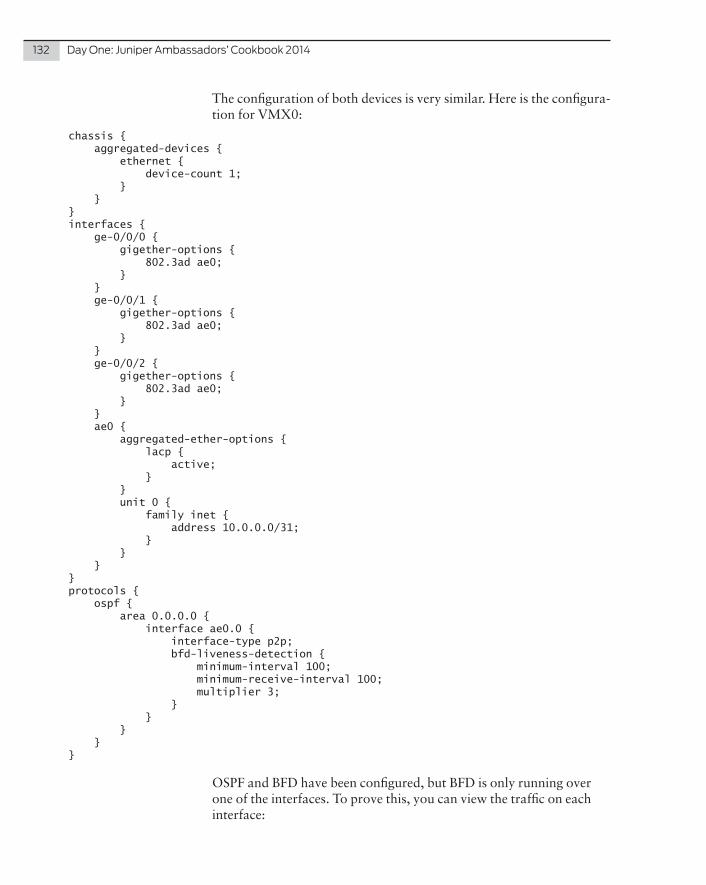
132 DayOne:JuniperAmbassadors’Cookbook2014
The configuration of both devices is very similar. Here is the configura-tion for VMX0:
chassis { aggregated-devices { ethernet { device-count 1; } }}interfaces { ge-0/0/0 { gigether-options { 802.3ad ae0; } } ge-0/0/1 { gigether-options { 802.3ad ae0; } } ge-0/0/2 { gigether-options { 802.3ad ae0; } } ae0 { aggregated-ether-options { lacp { active; } } unit 0 { family inet { address 10.0.0.0/31; } } }}protocols { ospf { area 0.0.0.0 { interface ae0.0 { interface-type p2p; bfd-liveness-detection { minimum-interval 100; minimum-receive-interval 100; multiplier 3; } } } }}
OSPF and BFD have been configured, but BFD is only running over one of the interfaces. To prove this, you can view the traffic on each interface:

Recipe17:CreatingIndependentMicroBFDSessionsforLAG 133
juniper@VMX0> monitor traffic interface ge-0/0/0 no-resolveverbose output suppressed, use <detail> or <extensive> for full protocol decodeAddress resolution is OFF.Listening on ge-0/0/0, capture size 96 bytes
03:04:58.666117 Out IP 10.0.0.0.49152 > 10.0.0.1.3784: BFDv1, One-hop Control, State Up, Flags: [none], length: 2403:04:58.756095 Out IP 10.0.0.0.49152 > 10.0.0.1.3784: BFDv1, One-hop Control, State Up, Flags: [none], length: 24
Ge-0/0/1 and ge-0/0/2 only have LACP frames entering and exiting the interfaces:
juniper@VMX0> monitor traffic interface ge-0/0/1 no-resolveverbose output suppressed, use <detail> or <extensive> for full protocol decodeAddress resolution is OFF.Listening on ge-0/0/1, capture size 96 bytes
03:05:24.836493 Out LACPv1, length 6003:05:25.388932 In LACPv1, length 6003:05:25.846179 Out LACPv1, length 6003:05:26.400433 In LACPv1, length 60
You can also see the single session here:
juniper@VMX0> show bfd session extensive Detect TransmitAddress State Interface Time Interval Multiplier10.0.0.1 Up ae0.0 0.300 0.100 3Client OSPF realm ospf-v2 Area 0.0.0.0, TX interval 0.100, RX interval 0.100
The issue here is that if ge-0/0/1 or ge-0/0/2 can’t reach the other side, it will not be found out until LACP times out. In the meantime, the router will continue to hash traffic over the affected link, which will blackhole those frames. Let’s fix it.
Solution
RFC7130 was created to address this issue. The RFC specifies that a separate BFD session is run over each LACP member interface. Juniper added support for this RFC in Junos OS 13.3, by enabling BFD under the aggregated interface. Each member interface then runs a separate BFD session to its neighbor’s member interface.
The configuration:
juniper@VMX0> show configuration interfaces ae0aggregated-ether-options { bfd-liveness-detection { minimum-interval 50; minimum-receive-interval 50; multiplier 3; neighbor 10.0.0.1; local-address 10.0.0.0; } lacp {

134 DayOne:JuniperAmbassadors’Cookbook2014
active; }}unit 0 { family inet { address 10.0.0.0/31; }}
If you check the BFD sessions, you’ll notice a separate session for each member interface as well as the original OSPF BFD session. Checking the session detail you’ll notice the client is LACPD and the session is micro BFD. All three member interfaces show the same output:
juniper@VMX0> show bfd session detail Detect TransmitAddress State Interface Time Interval Multiplier10.0.0.1 Up ge-0/0/2 0.300 0.050 3 Client LACPD, TX interval 0.050, RX interval 0.050 Session up time 00:01:13, previous down time 00:00:01 Local diagnostic None, remote diagnostic None Remote state Up, version 1 Session type: Micro BFD Detect TransmitAddress State Interface Time Interval Multiplier10.0.0.1 Up ge-0/0/1 0.300 0.050 3 Client LACPD, TX interval 0.050, RX interval 0.050 Session up time 00:01:13, previous down time 00:00:01 Local diagnostic None, remote diagnostic None Remote state Up, version 1 Session type: Micro BFD Detect TransmitAddress State Interface Time Interval Multiplier10.0.0.1 Up ge-0/0/0 0.300 0.100 3 Client LACPD, TX interval 0.050, RX interval 0.050 Session up time 00:02:24, previous down time 00:00:00 Local diagnostic None, remote diagnostic None Remote state Up, version 1 Session type: Micro BFD
Discussion
If you are following best practice, then you will have a control plane filter on your device. Micro BFD uses a different port number than BFD so you need to ensure you’re allowing that traffic to get though. Micro BFD uses UDP port 6784:
juniper@VMX0> ...wall family inet filter PROTECT_RE term MICRO_BFDfrom { protocol udp; port 6784;}then { accept;}
Problem
The Junos Unified Threat Management (UTM) suite includes such features as Antispam, Web Filtering, and Content Filtering, as well as Antivirus. These features are powerful in offering additional protection on the edge of your network. However, a significant portion of network administrators do not take advan-tage of these features for several reasons, such as the need to purchase a license and the need to create additional configuration, as well as concerns about possible performance issues.
Solution
This recipe shows you how to quickly generate trial license keys (which are good for 30 days) and how to just as quickly configure and check the work of one of the key UTM features, the Juniper-Kaspersky full file-based antivirus, which allows for antivirus protection using one of the industry’s best engines, including protection from different sorts of malware and polymorphic viruses in your HTTP, FTP, and mail traffic. Using a trial license allows you to try and then buy, if you deem appropriate, as well as helping you to become familiar with the antivirus and its deployment for when you do purchase this item. Note that you can only obtain a trial license once per year for each device serial number.
This recipe should work on any high-memory SRX branch model
Recipe 18
Quick Configuration of the Juniper-Kaspersky Antivirus on the SRX
by Petr Klimaj

136 DayOne:JuniperAmbassadors’Cookbook2014
(SRX branch devices are the SRX100 to SRX650, inclusive). To check the model of your device, issue the following command:
pk@inet-gw> show chassis hardware detail | match chassis Chassis XXXXXXXXXX SRX210H
If you have an H or H2 at the end of your device model number, such as the SRX210H shown, then you can proceed with this UTM configu-ration.
The configuration prerequisites are an Internet connection (typically, a default route to your ISP) and a configured DNS server. For example, these parts of your configuration may look like this:
pk@inet-gw> show configuration | display set | match "name-server|0.0.0.0" set system name-server 8.8.8.8set routing-options static route 0.0.0.0/0 next-hop 192.168.1.254
It is assumed that you do not have a Juniper-Kaspersky antivirus license yet, but to check if you already do, issue this command:
pk@inet-gw> show system license
Which will show all licenses installed on the device. Now, to actually generate the trial keys, use this command:
pk@inet-gw> request system license update trial
(DNS and an Internet connection to the Juniper support systems are required to receive the keys.) Repeat the show system license com-mand in a couple of minutes to see if the keys have been added to the box. You should see something like:
pk@inet-gw> show system license License usage: Licenses Licenses Licenses Expiry Feature name used installed needed av_key_kaspersky_engine 0 1 0 2014-07-04 00:00:00 UTC.............
NOTE If you see no licenses, check the log for errors.
Now that you have a license, you’ve got to configure the UTM feature – antivirus, in our case. There is some theory below, but note that you only actually need one command to make it start working!
To configure UTM on the Juniper SRX, you generally need to set up the following configuration blocks:
� A UTM feature profile that specifies the particular settings of the feature (in this case, antivirus);
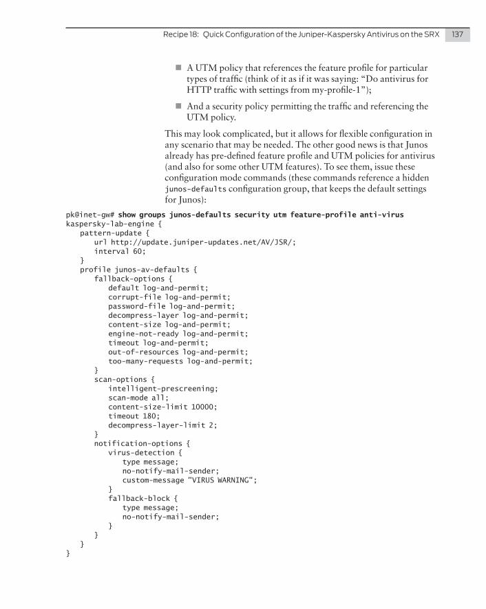
Recipe18:QuickConfigurationoftheJuniper-KasperskyAntivirusontheSRX 137
� A UTM policy that references the feature profile for particular types of traffic (think of it as if it was saying: “Do antivirus for HTTP traffic with settings from my-profile-1”);
� And a security policy permitting the traffic and referencing the UTM policy.
This may look complicated, but it allows for flexible configuration in any scenario that may be needed. The other good news is that Junos already has pre-defined feature profile and UTM policies for antivirus (and also for some other UTM features). To see them, issue these configuration mode commands (these commands reference a hidden junos-defaults configuration group, that keeps the default settings for Junos):
pk@inet-gw# show groups junos-defaults security utm feature-profile anti-virus kaspersky-lab-engine { pattern-update { url http://update.juniper-updates.net/AV/JSR/; interval 60; } profile junos-av-defaults { fallback-options { default log-and-permit; corrupt-file log-and-permit; password-file log-and-permit; decompress-layer log-and-permit; content-size log-and-permit; engine-not-ready log-and-permit; timeout log-and-permit; out-of-resources log-and-permit; too-many-requests log-and-permit; } scan-options { intelligent-prescreening; scan-mode all; content-size-limit 10000; timeout 180; decompress-layer-limit 2; } notification-options { virus-detection { type message; no-notify-mail-sender; custom-message "VIRUS WARNING"; } fallback-block { type message; no-notify-mail-sender; } } }}

138 DayOne:JuniperAmbassadors’Cookbook2014
pk@inet-gw# show groups junos-defaults security utm utm-policy junos-av-policy anti-virus { http-profile junos-av-defaults; ftp { upload-profile junos-av-defaults; download-profile junos-av-defaults; } smtp-profile junos-av-defaults; pop3-profile junos-av-defaults; imap-profile junos-av-defaults;}
You can see the already configured junos-av-defaults UTM feature profile that is referenced by the junos-av-policy. The particular settings in the default profile will depend on the hardware. You can create your own feature profiles and policies (using the default ones as the examples), or just use the defaults. If you do so, the only thing you need to enable UTM is to add reference to the UTM policy in all your security policies that you want to process traffic with antivirus.
For example, if you have a policy permitting HTTP and FTP from Trust to Untrust zone:
pk@inet-gw# show security policies from-zone Trust to-zone Untrust policy Trust-to-Untrust { match { source-address any; destination-address any; application [ junos-http junos-ftp ]; } then { permit; } }}
Use the following command to enable antivirus, then check the result:
pk@inet-gw# set security policies from-zone Trust to-zone Untrust policy Trust-to-Untrust then permit application-services utm-policy junos-av-policy
pk@inet-gw# show security policies from-zone Trust to-zone Untrustfrom-zone Trust to-zone Untrust { policy Trust-to-Untrust { match { source-address any; destination-address any; application [ junos-http junos-ftp ]; } then { permit { application-services { utm-policy junos-av-policy; } }

Recipe18:QuickConfigurationoftheJuniper-KasperskyAntivirusontheSRX 139
} } }
Don’t forget to commit. ; )
Now check if the antivirus UTM feature is working and if the virus database has been loaded to SRX (it is updated automatically every 60 minutes by default) with the following command:
pk@inet-gw> show security utm anti-virus status UTM anti-virus status: Anti-virus key expire date: 2014-07-04 00:00:00 Update server: http://update.juniper-updates.net/AV/SRX240/ Interval: 60 minutes Pattern update status: next update in 52 minutes Last result: new database loaded Anti-virus signature version: 06/21/2014 20:24 GMT, virus records: 561261 Anti-virus signature compiler version: N/A Scan engine type: kaspersky-lab-engine Scan engine information: last action result: No error(0x00000000)
Now let’s do a test of the newly installed Juniper-Kaspersky antivirus, downloading an EICAR test file from a server to the end host (this harmless file used for antivirus checks is available from http://www.eicar.org):
lab@host> ftp 192.168.1.112Connected to 192.168.1.112.220 (vsFTPd 2.0.5)Name (192.168.1.112:lab): lab331 Please specify the password.Password:230 Login successful.Remote system type is UNIX.Using binary mode to transfer files.ftp> get eicar.comlocal: eicar.com remote: eicar.com200 PORT command successful. Consider using PASV.150 Opening BINARY mode data connection for eicar.com (68 bytes). 0% | 100% |**********************************************************************************************************************************************************| 95 --:-- ETA550 192.168.1.112:21->10.1.0.15:51306 VIRUS WARNING For eicar.com with virus EICAR-Test-File.95 bytes received in 0.00 seconds (129.03 KB/s)ftp> bye221 Goodbye.
As you should see, the file was not downloaded (actually, its content was replaced with a virus warning, and the same warning was present-ed to you by the FTP client). You could also check the logs and stats:

140 DayOne:JuniperAmbassadors’Cookbook2014
pk@inet-gw> show log messages | match AV_VIRUS Mar 24 06:18:31 inet-gw RT_UTM: AV_VIRUS_DETECTED_MT: AntiVirus: Virus detected: from 192.168.1.112:20 to 10.1.0.15:14375 source-zone Untrust eicar.com file eicar.com virus EICAR-Test-File URL:http://www.viruslist.com/en/search?VN=EICAR-Test-File username N/A roles N/A
pk@inet-gw> show security utm anti-virus statistics UTM Anti Virus statistics:
Intelligent-prescreening passed: 0 MIME-whitelist passed: 0 URL-whitelist passed: 0
Scan Mode: scan-all: 1 Scan-extension: 0 Scan Request:
Total Clean Threat-found Fallback 1 0 1 0.....
You can see that at this point the antivirus is working fine.
Discussion
The use of Juniper-Kaspersky antivirus on your firewall is advanta-geous even if you already have another antivirus solution deployed on the end hosts. The basic configuration of Kaspersky antivirus on the Juniper SRX is extremely simple, and you can even test the feature at any time with a trial license key.
References
For more information about antivirus configuration on the SRX and available options, see, for example, these application notes: http://www.juniper.net/us/en/local/pdf/app-notes/3500158-en.pdf
http://www.juniper.net/us/en/local/pdf/app-notes/3500153-en.pdf
Or review these Knowledge Base articles: http://kb.juniper.net/InfoCenter/index?page=content&id=KB16620
http://kb.juniper.net/InfoCenter/index?page=content&id=KB17283
For the full Juniper technical documentation, go to: http://www.juniper.net/techpubs/