day 3 lab basic - apnic conferences – apnic 1: initial mpls vpn setup lab 2: running ospf between...
TRANSCRIPT

LAB 1: Initial MPLS VPN Setup LAB 2: Running OSPF between PE and CE Routers
LAB 3: Running BGP between PE and CE Routers
LAB 4: Overlapping VPNs
LAB 1: Initial MPLS VPN Setup
Introduction: Introduction
Welcome to the Module 3 Lab. Please progress through the steps in this lab, performing the configuration and troubleshooting exercises found in each step. A topology for the lab is supplied in order to give you a visual representation of the devices you are working with. Use the supplied interface to interact with the devices and complete the lab.
Step 1: Command list.
VPN-Related Commands: address-family ipv4 vrf vrf-name - Selects a per-VRF instance of a routing protocol. address-family vpnv4 - Selects VPNv4 address family configuration. ip vrf forwarding vrf-name - Assigns an interface to a VRF. ip vrf vrf-name - Creates a virtual routing and forwarding table (VRF). neighbor ip-address activate - Activates exchange of routes from address family under configuration for specified neighbor. neighbor ip-address route-reflector-client - Configures a route reflector client on a route reflector. neighbor next-hop-self - To configure the router as the next hop for a BGP-speaking neighbor or peer group, use the neighbor next-hop-self router configuration command. To disable this feature, use the no form of this command. neighbor remote-as - To add an entry to the BGP or Multiprotocol Border Gateway Protocol(MP-BGP) neighbor table, use the neighbor remote-as router configuratio n command. To remove an entry from the table, use the no form of this command. neighbor send-community - To specify that a communities attribute should be sent to a BGP neighbor, use the neighbor send-community command in address family or router configuration mode. To remove the entry, use the no form of this command. neighbor update-source - To have the Cisco IOS software allow Internal Border Gateway Protocol (IBGP) sessions to use any operational interface for TCP connections, use the neighbor update-source router configuration command. To restore the interface assignment to the closest interface, which is called the "best local address," use the no form of this command. ping vrf vrf-name host - Pings a host reachable through the specified VRF. rd value - Assigns a route distinguisher (RD) to a VRF. redistribute bgp as-number metric transparent - Redistributes BGP routes into RIP with propagation of the multi-exit discriminator (MED) into the RIP hop count. router bgp as-number - Selects BGP configuration. route-target import|export value - Assigns a route target (RT) to a VRF.

show ip bgp neighbor - Displays information on global BGP neighbors. show ip bgp vpnv4 vrf vrf-name - Displays VPN IPv4 (VPNv4) routes associated with the specified VRF. show ip route vrf vrf-name - Displays an IP routing table of the specified VRF. show ip vrf detail - Displays detailed VRF information. telnet host /vrf vrf-name - Telnets to a CE router connected to the specified VRF
Step 2: Configuring Multiprotocol BGP (MBGP).
In this task, you will configure MP-BGP between the PE routers in your workgroup. You will configure MP-BGP on PE11, and PE12. - Activate the BGP process on both PE routers using AS 65001 as the AS number. - Activate VPNv4 BGP sessions between the PE routers.
Step 3: Verification.
You have completed this exercise when you attain these results: -Display the BGP neighbor information and ensure that BGP sessions have been established between the two PE routers. PE11#sh ip bgp sum BGP router identifier 192.168.1.17, local AS number 65001 BGP table version is 1, main routing table version 1 Neighbor V AS MsgRcvd MsgSent TblVer InQ OutQ Up/Down State/PfxRcd 192.168.1.33 4 65001 6 6 1 0 0 00:02:23 0 PE12#sh ip bgp sum BGP router identifier 192.168.1.33, local AS number 65001 BGP table version is 1, main routing table version 1 Neighbor V AS MsgRcvd MsgSent TblVer InQ OutQ Up/Down State/PfxRcd 192.168.1.17 4 65001 9 9 1 0 0 00:05:24 0 PE11#sh bgp nei BGP neighbor is 192.168.1.33, remote AS 65001, internal link BGP version 4, remote router ID 192.168.1.33 BGP state = Established, up for 00:03:39 Last read 00:00:39, hold time is 180, keepalive interval is 60 seconds Neighbor capabilities: Route refresh: advertised and received (old and new) Address family IPv4 Unicast: advertised and received IPv4 MPLS Label capability: Received 7 messages, 0 notifications, 0 in queue Sent 7 messages, 0 notifications, 0 in queue Default minimum time between advertisement runs is 5 seconds For address family: IPv4 Unicast BGP table version 1, neighbor version 1 Index 1, Offset 0, Mask 0x2 Route refresh request: received 0, sent 0 0 accepted prefixes consume 0 bytes Prefix advertised 0, suppressed 0, withdrawn 0 Connections established 1; dropped 0 Last reset never Connection state is ESTAB, I/O status: 1, unread input bytes: 0 Local host: 192.168.1.17, Local port: 11022 Foreign host: 192.168.1.33, Foreign port: 179

Enqueued packets for retransmit: 0, input: 0 mis-ordered: 0 (0 bytes) Event Timers (current time is 0xA12E784): Timer Starts Wakeups Next Retrans 8 0 0x0 TimeWait 0 0 0x0 AckHold 7 5 0x0 SendWnd 0 0 0x0 KeepAlive 0 0 0x0 GiveUp 0 0 0x0 PmtuAger 0 0 0x0 DeadWait 0 0 0x0 iss: 1596106025 snduna: 1596106185 sndnxt: 1596106185 sndwnd: 16225 irs: 2134453172 rcvnxt: 2134453332 rcvwnd: 16225 delrcvwnd: 159 SRTT: 197 ms, RTTO: 984 ms, RTV: 787 ms, KRTT: 0 ms minRTT: 44 ms, maxRTT: 300 ms, ACK hold: 200 ms Flags: higher precedence, nagle Datagrams (max data segment is 536 bytes): Rcvd: 8 (out of order: 0), with data: 7, total data bytes: 159 Sent: 14 (retransmit: 0, fastretransmit: 0), with data: 7, total data bytes: 159
Step 4: Configuring virtual routing and forwarding tables.
In this task and the following task, you will establish simple VPNs for customer A. You will establish a VPN connections between CE11A and CE12A; as well as CE11B and CE12B. You are also responsible for all PE router configurations related to its customer. -Design your VPN networks-decide on the RD and the RT numbering. NOTE: The easiest numbering plan would be to use the same values for the RD and the RT. Use simple values, for example, 1:10 for customer A and 1:20 for customer B. -Create (2) VRFs on the PE routers and associate the PE-CE interfaces into the proper VRFs; use simple yet descriptive VRF names (for example, "CE11A" and "CE11B"). -Your customer is using RIP as its IGP, so enable RIP for the VRF that you have created. -Configure redistribution of RIP into BGP within the ipv4 vrf address family. -Configure redistribution of BGP into RIP within the ipv4 vrf address family. -Configure RIP metric propagation through MP-BGP by using the redistribute bgp metric transparent command in the RIP process. -Ensure that RIP is enabled on all the CE routers. Make sure that all the networks (including loopbacks) are active in the RIP process.
Step 5: Verification.
You have completed this exercise when you attain these results: -Verify that you have the proper configuration of your virtual routing and forwarding (VRF) tables with show ip vrf detail. You should get a printout similar to the one here: PE11#sh ip vrf detail VRF Customer_A; default RD 1:10; default VPNID <notset> Interfaces: Serial0/0.101 Connected addresses are not in global routing table Export VPN route-target communities RT:1:10 Import VPN route-target communities

RT:1:10 No import route-map No export route-map -Check the routing protocols running in your VRF with the show ip protocol vrf command. When executed on PE12, it will produce a printout similar to the one here: PE11#sh ip prot vrf Customer_A Routing Protocol is "bgp 65001" Outgoing update filter list for all interfaces is not set Incoming update filter list for all interfaces is not set IGP synchronization is disabled Automatic route summarization is disabled Redistributing: rip Maximum path: 1 Routing Information Sources: Gateway Distance Last Update 192.168.1.33 200 15:05:06 Distance: external 20 internal 200 local 200 Routing Protocol is "rip" Sending updates every 30 seconds, next due in 26 seconds Invalid after 180 seconds, hold down 180, flushed after 240 Outgoing update filter list for all interfaces is not set Incoming update filter list for all interfaces is not set Redistributing: bgp 65001, rip Default version control: send version 2, receive version 2 Interface Send Recv Triggered RIP Key-chain Serial0/0.101 2 2 Maximum path: 4 Routing for Networks: Interface Send Recv Triggered RIP Key-chain ` 10.0.0.0 150.1.0.0 Routing Information Sources: Gateway Distance Last Update 150.1.11.17 120 00:00:27 Distance: (default is 120) -Verify the per-VRF routing table on the PE router with the show ip route vrf command. It will produce a printout similar to the one here: PE11#sh ip route vrf Customer_A Codes: C - connected, S - static, R - RIP, M - mobile, B - BGP D - EIGRP, EX - EIGRP external, O - OSPF, IA - OSPF inter area N1 - OSPF NSSA external type 1, N2 - OSPF NSSA external type 2 E1 - OSPF external type 1, E2 - OSPF external type 2 i - IS-IS, L1 - IS-IS level-1, L2 - IS-IS level-2, ia - IS-IS inter area * - candidate default, U - per-user static route, o - ODR P - periodic downloaded static route Gateway of last resort is not set 10.0.0.0/8 is variably subnetted, 4 subnets, 2 masks B 10.1.11.49/32 [200/1] via 192.168.1.33, 15:10:04 R 10.1.11.49/32 [120/1] via 150.1.11.17, 00:00:24, Serial0/0.101 B 10.1.11.16/28 [200/1] via 192.168.1.33, 15:10:04 R 10.1.11.16/28 [120/1] via 150.1.11.17, 00:00:24, Serial0/0.101 150.1.0.0/28 is subnetted, 2 subnets B 150.1.11.16 [200/0] via 192.168.1.33, 15:46:04 C 150.1.11.16 is directly connected, Serial0/0.101 -Use the show ip bgp vpnv4 vrf command to display the BGP routing table associated with a VRF. The printout from the PE11 router is shown here:
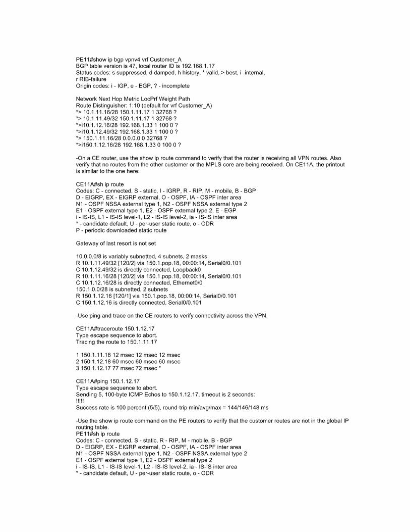
PE11#show ip bgp vpnv4 vrf Customer_A BGP table version is 47, local router ID is 192.168.1.17 Status codes: s suppressed, d damped, h history, * valid, > best, i -internal, r RIB-failure Origin codes: i - IGP, e - EGP, ? - incomplete Network Next Hop Metric LocPrf Weight Path Route Distinguisher: 1:10 (default for vrf Customer_A) *> 10.1.11.16/28 150.1.11.17 1 32768 ? *> 10.1.11.49/32 150.1.11.17 1 32768 ? *>i10.1.12.16/28 192.168.1.33 1 100 0 ? *>i10.1.12.49/32 192.168.1.33 1 100 0 ? *> 150.1.11.16/28 0.0.0.0 0 32768 ? *>i150.1.12.16/28 192.168.1.33 0 100 0 ? -On a CE router, use the show ip route command to verify that the router is receiving all VPN routes. Also verify that no routes from the other customer or the MPLS core are being received. On CE11A, the printout is similar to the one here: CE11A#sh ip route Codes: C - connected, S - static, I - IGRP, R - RIP, M - mobile, B - BGP D - EIGRP, EX - EIGRP external, O - OSPF, IA - OSPF inter area N1 - OSPF NSSA external type 1, N2 - OSPF NSSA external type 2 E1 - OSPF external type 1, E2 - OSPF external type 2, E - EGP i - IS-IS, L1 - IS-IS level-1, L2 - IS-IS level-2, ia - IS-IS inter area * - candidate default, U - per-user static route, o - ODR P - periodic downloaded static route Gateway of last resort is not set 10.0.0.0/8 is variably subnetted, 4 subnets, 2 masks R 10.1.11.49/32 [120/2] via 150.1.pop.18, 00:00:14, Serial0/0.101 C 10.1.12.49/32 is directly connected, Loopback0 R 10.1.11.16/28 [120/2] via 150.1.pop.18, 00:00:14, Serial0/0.101 C 10.1.12.16/28 is directly connected, Ethernet0/0 150.1.0.0/28 is subnetted, 2 subnets R 150.1.12.16 [120/1] via 150.1.pop.18, 00:00:14, Serial0/0.101 C 150.1.12.16 is directly connected, Serial0/0.101 -Use ping and trace on the CE routers to verify connectivity across the VPN. CE11A#traceroute 150.1.12.17 Type escape sequence to abort. Tracing the route to 150.1.11.17 1 150.1.11.18 12 msec 12 msec 12 msec 2 150.1.12.18 60 msec 60 msec 60 msec 3 150.1.12.17 77 msec 72 msec * CE11A#ping 150.1.12.17 Type escape sequence to abort. Sending 5, 100-byte ICMP Echos to 150.1.12.17, timeout is 2 seconds: !!!!! Success rate is 100 percent (5/5), round-trip min/avg/max = 144/146/148 ms -Use the show ip route command on the PE routers to verify that the customer routes are not in the global IP routing table. PE11#sh ip route Codes: C - connected, S - static, R - RIP, M - mobile, B - BGP D - EIGRP, EX - EIGRP external, O - OSPF, IA - OSPF inter area N1 - OSPF NSSA external type 1, N2 - OSPF NSSA external type 2 E1 - OSPF external type 1, E2 - OSPF external type 2 i - IS-IS, L1 - IS-IS level-1, L2 - IS-IS level-2, ia - IS-IS inter area * - candidate default, U - per-user static route, o - ODR

P - periodic downloaded static route Gateway of last resort is not set 192.168.1.0/24 is variably subnetted, 7 subnets, 2 masks D 192.168.1.97/32 [90/2809856] via 192.168.1.50, 19:14:54, Serial0/0.111 D 192.168.1.112/28 [90/2681856] via 192.168.1.50, 19:14:54, Serial0/0.111 D 192.168.1.64/28 [90/3193856] via 192.168.1.50, 19:14:54, Serial0/0.111 D 192.168.1.81/32 [90/2297856] via 192.168.1.50, 19:14:54, Serial0/0.111 D 192.168.1.33/32 [90/3321856] via 192.168.1.50, 19:14:54, Serial0/0.111 C 192.168.1.48/28 is directly connected, Serial0/0.111 C 192.168.1.17/32 is directly connected, Loopback0 -Use ping and trace on the PE routers to verify that you cannot reach your customer networks from global address space. PE11#ping 150.1.12.17 Type escape sequence to abort. Sending 5, 100-byte ICMP Echos to 150.1.12.17, timeout is 2 seconds: ..... Success rate is 0 percent (0/5) PE11#ping 150.1.12.33 Type escape sequence to abort. Sending 5, 100-byte ICMP Echos to 150.1.12.33, timeout is 2 seconds: ..... -Use the ping vrf command on the PE routers to verify that you can reach your customer networks from global address space. PE11#ping vrf Customer_A 150.1.12.17 Type escape sequence to abort. Sending 5, 100-byte ICMP Echos to 150.1.12.17, timeout is 2 seconds: !!!! Success rate is 100 percent (5/5), round-trip min/avg/max = 28/31/36 ms PE12#ping vrf Customer_A 150.1.12.17 Type escape sequence to abort. Sending 5, 100-byte ICMP Echos to 150.1.12.17, timeout is 2 seconds: !!!!! Success rate is 100 percent (5/5), round-trip min/avg/max = 116/117/120 ms -Use the ping vrf command on the PE routers to verify that you can reach your customer networks from global address space. PE11#ping vrf Customer_A 150.1.12.17 Type escape sequence to abort. Sending 5, 100-byte ICMP Echos to 150.1.12.17, timeout is 2 seconds: !!!! Success rate is 100 percent (5/5), round-trip min/avg/max = 28/31/36 ms PE12#ping vrf Customer_A 150.1.11.17 Type escape sequence to abort. Sending 5, 100-byte ICMP Echos to 150.1.12.17, timeout is 2 seconds: !!!!! Success rate is 100 percent (5/5), round-trip min/avg/max = 116/117/120 ms
Step 6: Solution.
The solution to this lab can be found at
Conclusion: Conclusion
Congratulations on completing this lab. Feel free to experiment with what you have learned, or continue to work on the devices.

LAB 2: Running OSPF between PE and CE Routers
Introduction: Introduction
WelcomeWelcome to MPLS Lab 5: Running OSPF between PE and CE Routers. Please progress through the steps in this lab, performing the configuration and troubleshooting exercises found in each step. A topology for the lab is supplied in order to give you a visual representation of the devices you are working with. Use the supplied interface to interact with the devices and complete the lab.
Step 1: Command list.
OSPF Commands address-family ipv4 vrf vrf-name - Selects a per-VRF instance of a routing protocol. default-information originate always - Generates a default route into OSPF. ip vrf forwarding vrf-name - Assigns an interface to a VRF. ip vrf vrf-name - Creates a virtual routing and forwarding table (VRF). ping vrf vrf-name host - Pings a host reachable through the specified VRF. rd value - Assigns an RD to a VRF. redistribute bgp as-number subnets - Redistributes BGP routes (including subnet routes) into OSPF. router bgp as-number - Selects BGP configuration. router ospf process vrf vrf-name - Starts an OSPF process within the specified VRF. route-target import|export value - Assigns an RT to a VRF. show ip bgp vpnv4 vrf vrf-name - Displays VPNv4 routes associated with the specified VRF. show ip ospf database - Displays OSPF database information. show ip route vrf vrf-name - Displays an IP routing table of the specified VRF. show ip vrf detail - Displays detailed VRF information. telnet host /vrf vrf-name - Telnets to a CE router connected to the specified VRF.
Step 2: Configuring virtual routing and forwarding tables
The customer is performing a phase conversion of its IGP to OSPF. In this task your customer has decided to convert the site running RIP to OSPF. You will convert the customer A site 2, CE12A, from RIP to OSPF and establish a simple VPN. -Disable RIP on the CE 12A routers of your customer. -Configure OSPF on the CE routers of your customer. (Use an OSPF process ID of 1). Use the areas in the CE router as detailed here. Area Interface(s) Area 0 WAN interface toward PE router Loopback 0

Area 1 E0/0 -Configure OSPF (use an OSPF process ID of 1) in the VRFs on PE 12 router using the router ospf vrf command. Use OSPF Area 0 on the PE-CE link. -Configure redistribution from OSPF to MP-BGP using the redistribute ospf command inside the VRF address family configuration. -Configure redistribution from MP-BGP to OSPF using the redistribute bgp subnets command in the OSPF router configuration.
Step 3: Verify
Verify the OSPF adjacency on the PE11 and PE12 routers using the show ip ospf neighbor command.
PE12#sh ip ospf nei Neighbor ID Pri State Dead Time Address Interface 10.1.12.65 0 FULL/ - 00:00:33 150.1.12.17 Serial0/0.101 -Check the OSPF topology database on CE12A. You should see router link states (resulting from OSPF connectivity between the PE and the CE routers) and type 5 external link states (all other VPN routes originated in RIP or BGP), but no summaries. A sample printout from CE12A is shown here:
CE12A#sh ip ospf data OSPF Router with ID (10.1.12.49) (Process ID 1) Router Link States (Area 0) Link ID ADV Router Age Seq# Checksum Link count 10.1.12.49 10.1.12.49 1941 0x80000005 0xE305 3 150.1.12.18 150.1.12.18 885 0x80000009 0x32B6 2 Summary Net Link States (Area 0) Link ID ADV Router Age Seq# Checksum 10.1.12.16 10.1.12.49 1941 0x80000002 0xE1B3 Router Link States (Area 1) Link ID ADV Router Age Seq# Checksum Link count 10.1.12.49 10.1.12.49 1941 0x80000002 0x3BE8 1 Summary Net Link States (Area 1) Link ID ADV Router Age Seq# Checksum 10.1.12.49 10.1.12.49 1941 0x80000002 0x96D7 150.1.12.16 10.1.12.49 1941 0x80000002 0xB817 Summary ASB Link States (Area 1) Link ID ADV Router Age Seq# Checksum 150.1.12.18 10.1.12.49 1944 0x80000002 0xF0CC Type-5 AS External Link States Link ID ADV Router Age Seq# Checksum Tag 10.1.11.16 150.1.12.18 347 0x80000001 0xEB62 3489725929 10.1.11.49 150.1.12.18 347 0x80000001 0x1775 3489725929 150.1.11.16 150.1.12.18 347 0x80000001 0x213E 3489725929 -Verify connectivity across the VPN by using ping and trace commands on the CE routers and ping vrf and

trace vrf commands on the PE routers.
CE12A#ping 10.1.11.49 Type escape sequence to abort. Sending 5, 100-byte ICMP Echos to 10.1.11.49, timeout is 2 seconds: !!!!! PE11#ping vrf Customer_A 10.1.12.49 Type escape sequence to abort. Sending 5, 100-byte ICMP Echos to 10.1.12.49, timeout is 2 seconds: !!!!! Success rate is 100 percent (5/5), round-trip min/avg/max = 116/119/120 ms PE12#ping vrf Customer_A 10.1.11.49 Type escape sequence to abort. Sending 5, 100-byte ICMP Echos to 10.1.11.49, timeout is 2 seconds: !!!!! Success rate is 100 percent (5/5), round-trip min/avg/max = 28/29/32 ms PE12#ping vrf Customer_A 10.1.12.49 Type escape sequence to abort. Sending 5, 100-byte ICMP Echos to 10.1.12.49, timeout is 2 seconds: !!!!! Success rate is 100 percent (5/5), round-trip min/avg/max = 116/118/120 ms PE11#trace vrf Customer_A 10.1.12.49 Type escape sequence to abort. Tracing the route to 10.1.12.49 1 150.1.12.17 60 msec 60 msec *
Step 4: Completing the OSPF migration.
Your customer has decided to have one IGP; OSPF. This decision means that the sites that are running EIGRP will have to be converted to OSPF. You will convert the customer A site 1, CE11A, from EIGRP to OSPF and establish a simple VPN. Disable EIGRP and configure OSPF on the CE 11A router. Configure OSPF (use an OSPF process ID of 1) areas in the CE router according to the information here. Area Interface(s) Area 0 WAN interface toward PE router Loopback 0 Area 1 E0/0 -Configure OSPF in the VRFs on PE routers using the router ospf vrf command. Use OSPF Area 0 on the PE-CE link. -Configure redistribution from OSPF to MP-BGP using the redistribute ospf command inside the VRF address family configuration. -Configure redistribution from MP-BGP to OSPF using the redistribute bgp subnets command in the OSPF router configuration.
Step 5: Verification.
Verify the OSPF adjacency on PE11 and PE12 routers using the show ip ospf neighbor command.
PE11#sh ip ospf nei Neighbor ID Pri State Dead Time Address Interface 10.1.11.65 0 FULL/ - 00:00:36 150.1.12.17 Serial0/0.101 PE12#sh ip ospf nei Neighbor ID Pri State Dead Time Address Interface 10.1.12.65 0 FULL/ - 00:00:39 150.1.12.17 Serial0/0.101 -Check the OSPF topology database on CE11A . You should see router link states (resulting from OSPF

connectivity between the PE and the CE routers) and type 5 external link states (all other VPN routes originated in RIP or BGP), but no summaries. A sample printout from CE11A is shown here:
CE11A#sh ip ospf data OSPF Router with ID (10.1.pop.65) (Process ID 1) Router Link States (Area 0) Link ID ADV Router Age Seq# Checksum Link count 10.1.11.65 10.1.11.65 965 0x80000003 0xD678 3 150.4.11.18 150.4.11.18 964 0x80000002 0xC71D 2 Summary Net Link States (Area 0) Link ID ADV Router Age Seq# Checksum 10.1.11.16 10.1.11.65 1271 0x80000001 0x95F2 10.1.12.16 150.1.11.18 969 0x80000001 0x97CE 10.1.12.49 150.1.11.18 969 0x80000001 0x4CF2 150.1.12.16 150.1.11.18 969 0x80000001 0x73AC Router Link States (Area 1) Link ID ADV Router Age Seq# Checksum Link count 10.1.11.65 10.1.11.65 1280 0x80000001 0x45C2 1 Summary Net Link States (Area 1) Link ID ADV Router Age Seq# Checksum 10.1.11.49 10.1.11.65 1281 0x80000001 0x4A17 10.1.12.16 10.1.11.65 983 0x80000001 0x172F 10.1.12.49 10.1.11.65 983 0x80000001 0xCB53 150.1.11.16 10.1.11.65 1303 0x80000001 0xF30E 150.1.12.16 10.1.11.65 983 0x80000001 0xF20D Summary ASB Link States (Area 1) Link ID ADV Router Age Seq# Checksum 150.1.11.18 10.1.11.65 983 0x80000001 0x2CC3 -Check the IP routing table on CE11A and note the OSPF interarea (IA) routes in the routing table.
CE11A#sh ip route Codes: C - connected, S - static, I - IGRP, R - RIP, M - mobile, B - BGP D - EIGRP, EX - EIGRP external, O - OSPF, IA - OSPF inter area N1 - OSPF NSSA external type 1, N2 - OSPF NSSA external type 2 E1 - OSPF external type 1, E2 - OSPF external type 2, E - EGP i - IS-IS, L1 - IS-IS level-1, L2 - IS-IS level-2, ia - IS-IS inter area * - candidate default, U - per-user static route, o - ODR P - periodic downloaded static route Gateway of last resort is not set 10.0.0.0/8 is variably subnetted, 5 subnets, 2 masks O IA 10.1.11.49/32 [110/66] via 150.4.pop.18, 00:31:44, Serial0/0.101 C 10.1.12.49/32 is directly connected, Loopback0 O IA 10.1.11.16/28 [110/75] via 150.4.pop.18, 00:31:44, Serial0/0.101 C 10.1.12.16/28 is directly connected, Ethernet0/0 C 10.1.11.64/28 is directly connected, Loopback1 150.1.0.0/28 is subnetted, 2 subnets O IA 150.1.11.16 [110/2] via 150.1.pop.18, 00:32:14, Serial0/0.101 C 150.1.12.16 is directly connected, Serial0/0.101 -Verify connectivity across the VPN by using ping and trace commands on the CE routers and ping vrf and trace vrf commands on the PE routers.
CE11A#ping 10.1.12.49 Type escape sequence to abort. Sending 5, 100-byte ICMP Echos to 10.1.12.49, timeout is 2 seconds: !!!!! Success rate is 100 percent (5/5), round-trip min/avg/max = 148/148/149 ms PE11#ping vrf Customer_A 10.1.12.49 Type escape sequence to abort. Sending 5, 100-byte ICMP Echos to 10.1.12.49, timeout is 2 seconds: !!!!!

Success rate is 100 percent (5/5), round-trip min/avg/max = 116/119/120 ms PE12#ping vrf Customer_A 10.1.11.49 Type escape sequence to abort. Sending 5, 100-byte ICMP Echos to 10.1.11.49, timeout is 2 seconds: !!!!! Success rate is 100 percent (5/5), round-trip min/avg/max = 28/29/32 ms PE11#ping vrf Customer_A 10.1.11.49 Type escape sequence to abort. Sending 5, 100-byte ICMP Echos to 10.1.11.49, timeout is 2 seconds: !!!!! Success rate is 100 percent (5/5), round-trip min/avg/max = 28/28/32 ms PE12#ping vrf Customer_A 10.1.12.49 Type escape sequence to abort. Sending 5, 100-byte ICMP Echos to 10.1.12.49, timeout is 2 seconds: !!!!! Success rate is 100 percent (5/5), round-trip min/avg/max = 116/118/120 ms !!!!! Success rate is 100 percent (5/5), round-trip min/avg/max = 116/118/120 ms PE11#trace vrf Customer_A 10.1.12.49 Type escape sequence to abort. Tracing the route to 10.1.12.49 1 150.1.12.17 60 msec 60 msec *
Step 6: Solution.
You can find the solution for this lab at:
Conclusion: Conclusion
Congratulations on completing this lab. Feel free to experiment with what you have learned, or continue to work on the devices.
LAB 3: Running BGP between PE and CE Routers
Introduction: Introduction
Welcome to the MPLS Lab 6: Running BGP between PE and CE Routers . Please progress through the steps in this lab, performing the configuration and troubleshooting exercises found in each step. A topology for the lab is supplied in order to give you a visual representation of the devices you are working with. Use the supplied interface to interact with the devices and complete the lab.
Step 1: Command list.
address-family ipv4 vrf vrf-name - Selects a per-VRF instance of a routing protocol. ip vrf forwarding vrf-name - Assigns an interface to a VRF. ip vrf vrf-name - Creates a virtual routing and forwarding table (VRF). neighbor ip-address as-override - To configure a PE router to override the AS number of a site with the AS number of a provider, use the neighbor as-override command in router configuration mode. To remove VPNv4 prefixes from a specified router, use the no form of this command. neighbor ip-address route-map name in|out - Applies a route map to BGP updates received from or sent to the specified neighbor. no neighbor ip-address shutdown - Enables a BGP neighbor previously disabled with the neighbor shutdown command. ping vrf vrf-name host - Pings a host reachable through the specified VRF. rd value - Assigns an RD to a VRF. route-map name permit seq - Creates an entry in a route map. router bgp as-number - Selects BGP configuration. route-target import|export value - Assigns an RT to a VRF. set metric value - Sets the BGP MED attribute in a route map. show ip bgp vpnv4 vrf vrf-name - Displays VPNv4 routes associated with the specified VRF. show ip route vrf vrf-name - Displays an IP routing table of the specified VRF. telnet host /vrf vrf-name - Telnets to a CE router connected to the specified VRF.
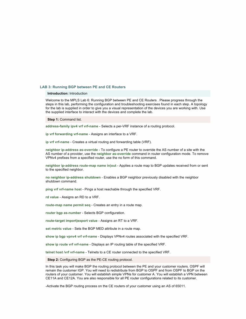
Step 2: Configuring BGP as the PE-CE routing protocol.
In this task you will make BGP the routing protocol between the PE and your customer routers. OSPF will remain the customer IGP. You will need to redistribute from BGP to OSPF and from OSPF to BGP on the routers of your customer. You will establish simple VPNs for customer A. You will establish a VPN between CE11A and CE12A. You are also responsible for all PE router configurations related to its customer. -Activate the BGP routing process on the CE routers of your customer using an AS of 65011.

-Remove OSPF on the associated PE router and activate the BGP neighbor relationship between each CE router and its associated PE router. -Because both of your customer sites are using the same AS number, you will need to re-enable the allowas-in feature.
Step 3: Verification.
-Check BGP connectivity with the show ip bgp summary command on the CE routers. CE11A#sh ip bgp sum BGP router identifier 10.1.11.49, local AS number 65011 BGP table version is 10, main routing table version 10 9 network entries and 9 paths using 1197 bytes of memory 2 BGP path attribute entries using 120 bytes of memory 1 BGP AS-PATH entries using 24 bytes of memory 0 BGP route-map cache entries using 0 bytes of memory 0 BGP filter-list cache entries using 0 bytes of memory BGP activity 9/30 prefixes, 9/0 paths, scan interval 60 secs Neighbor V AS MsgRcvd MsgSent TblVer InQ OutQ Up/Down State/PfxRcd 150.1.11.18 4 65011 617 618 10 0 0 09:50:35 3 CE11A#sh ip bgp BGP table version is 63, local router ID is 10.1.11.49 Status codes: s suppressed, d damped, h history, * valid, > best, i - internal Origin codes: i - IGP, e - EGP, ? - incomplete Network Next Hop Metric LocPrf Weight Path *> 10.1.11.16/28 0.0.0.0 0 32768 ? *> 10.1.11.49/32 0.0.0.0 0 32768 ? *> 150.1.12.16/28 150.1.11.18 32768 ? 65001 65001 ? *> 10.1.12.49/32 150.1.11.18 0 65001 65001 ? *> 150.1.12.16/28 150.1.11.18 32768 ? *> *> 150.1.11.16/28 0.0.0.0 0 32768 ? CE12A#sh ip bgp sum BGP router identifier 10.1.12.49, local AS number 65011 BGP table version is 22, main routing table version 22 7 network entries and 7 paths using 931 bytes of memory 2 BGP path attribute entries using 120 bytes of memory 1 BGP AS-PATH entries using 24 bytes of memory 0 BGP route-map cache entries using 0 bytes of memory 0 BGP filter-list cache entries using 0 bytes of memory BGP activity 14/33 prefixes, 14/7 paths, scan interval 60 secs Neighbor V AS MsgRcvd MsgSent TblVer InQ OutQ Up/Down State/PfxRcd 150.1.12.18 4 65001 638 637 22 0 0 10:10:56 4 CE12A#sh ip bgp BGP table version is 38, local router ID is 10.1.12.49 Status codes: s suppressed, d damped, h history, * valid, > best, i - internal Origin codes: i - IGP, e - EGP, ? - incomplete Network Next Hop Metric LocPrf Weight Path *> 10.1.11.16/28 150.1.12.18 0 65001 65001 ? *> 10.1.11.49/32 150.1.12.18 0 65001 65001 ? *> 10.1.12.16/28 0.0.0.0 0 32768 ? *> 10.1.12.49/32 0.0.0.0 0 32768 ? *> 150.4.11.16/28 150.1.12.18 0 65001 65001 ? *> 150.4.12.16/28 0.0.0.0 0 32768 ? PE11#sh ip bgp vpn all BGP table version is 145, local router ID is 192.168.1.17 Status codes: s suppressed, d damped, h history, * valid, > best, i - internal, r RIB-failure, S Stale

Origin codes: i - IGP, e - EGP, ? - incomplete Network Next Hop Metric LocPrf Weight Path Route Distinguisher: 1:10 (default for vrf Customer_A) *> 10.1.11.16/28 150.1.11.17 0 0 65001 ? *> 10.1.11.49/32 150.1.11.17 0 0 65001 ? * i10.1.12.16/28 192.168.1.33 0 100 0 65001 ? * i10.1.12.49/32 192.168.1.33 0 100 0 65001 ? r> 150.1.11.16/28 150.1.11.17 0 0 65001 ? r i150.1.11.48/28 192.168.1.33 0 100 0 65001 ? * i150.1.12.16/28 192.168.1.33 0 100 0 65001 ? PE11#sh ip bgp vpnv4 all BGP table version is 74, local router ID is 192.168.1.33 Status codes: s suppressed, d damped, h history, * valid, > best, i - internal, r RIB-failure, S Stale Origin codes: i - IGP, e - EGP, ? - incomplete Network Next Hop Metric LocPrf Weight Path Route Distinguisher: 1:10 (default for vrf Customer_A) *>i10.1.11.16/28 192.168.1.17 0 100 0 65011 ? *>i10.1.11.49/32 192.168.1.17 0 100 0 65011 ? *> 10.1.12.16/28 150.1.12.17 0 0 65011 ? *> 10.1.12.49/32 150.1.12.17 0 0 65011 ? *>i150.4.11.16/28 192.168.1.17 0 100 0 65011 ? r> 150.4.12.16/28 150.1.12.17 0 0 65011 ?
Step 4: Configuring the backup PE-CE link.
In this task you will enable the backup links on the PE routers. You will establish the link between its CE12A router and the PE11. Ensure that the interface is added to the proper VRF and BGP is activated. -Configure an additional subinterface on the existing serial interfaces on your PE and CE routers. - Add the backup link to the appropriate VRF. Which VRF is CE12A added to? -Configure IP addresses and DLCIs on this interface using the parameters below. Backup Link Configuration Parameters Source Router - CE12A IP Address - 150.1.11.49/28 DLCI - 113 Destination Router - PE11 IP Address - 150.1.11.50/28 DLCI - 113 - Activate the BGP neighbor relationship between your CE router and the appropriate PE router.
Step 5: Verification.
You have completed this exercise when you attain these results: CE12A#ping 150.1.11.50 Sending 5, 100-byte ICMP Echos to 150.1.11.50, timeout is 2 seconds: !!!!! Success rate is 100 percent (5/5), round-trip min/avg/max = 28/29/32 ms -Check BGP connectivity with the show ip bgp summary command on the CE routers. CE12A#sh ip bgp sum BGP router identifier 10.1.12.65, local AS number 65011 BGP table version is 10, main routing table version 10 9 network entries and 9 paths using 1197 bytes of memory 2 BGP path attribute entries using 120 bytes of memory

1 BGP AS-PATH entries using 24 bytes of memory 0 BGP route-map cache entries using 0 bytes of memory 0 BGP filter-list cache entries using 0 bytes of memory BGP activity 9/30 prefixes, 9/0 paths, scan interval 60 secs Neighbor V AS MsgRcvd MsgSent TblVer InQ OutQ Up/Down State/PfxRcd 150.1.11.50 4 65001 606 607 10 0 0 10:01:29 2 150.1.12.18 4 65001 617 618 10 0 0 09:50:35 3 CE12A#sh ip bgp BGP table version is 63, local router ID is 10.1.12.65 Status codes: s suppressed, d damped, h history, * valid, > best, i - internal Origin codes: i - IGP, e - EGP, ? - incomplete Network Next Hop Metric LocPrf Weight Path * 10.1.11.16/28 150.1.12.18 0 65001 65001 ? *> 150.1.11.50 0 65001 65001 ? * 10.1.11.49/32 150.1.12.18 0 65001 65001 ? *> 150.1.11.50 0 65001 65001 ? *> 10.1.12.16/28 0.0.0.0 0 32768 ? *> 10.1.12.49/32 0.0.0.0 0 32768 ? * 150.1.11.16/28 150.1.11.18 0 65001 65001 ? *> 150.1.12.50 0 65001 65001 ? *> 150.1.11.48/28 0.0.0.0 0 32768 ? *> 150.1.12.16/28 0.0.0.0 0 32768 ? PE11#sh ip bgp vpn all BGP table version is 145, local router ID is 192.168.1.17 Status codes: s suppressed, d damped, h history, * valid, > best, i - internal, r RIB-failure, S Stale Origin codes: i - IGP, e - EGP, ? - incomplete Network Next Hop Metric LocPrf Weight Path Route Distinguisher: 1:10 (default for vrf Customer_A) *> 10.1.11.16/28 150.1.11.17 0 0 65011 ? *> 10.1.11.49/32 150.1.11.17 0 0 65011 ? * i10.1.12.16/28 192.168.1.33 0 100 0 65011 ? *> 150.1.11.49 0 0 65011 ? * i10.1.12.49/32 192.168.1.33 0 100 0 65011 ? *> 150.1.11.49 0 0 65011 ? r> 150.1.11.16/28 150.1.11.17 0 0 65011 ? r i150.1.11.48/28 192.168.1.33 0 100 0 65011 ? r> 150.1.11.49 0 0 65011? * i150.1.12.16/28 192.168.1.33 0 100 0 65011 ? *> 150.1.11.49 0 0 65011 ?
Step 6: Selecting the primary and backup link with BGP.
It may be necessary to control the BGP selection of the link to establish a primary-backup relationship. In this task, you will use the local preference and MED attributes to control link selection. In this implementation, the new link bypasses the MPLS core. However, because it a high-cost link, it should be considered only as the backup link; the link through the MPLS core is to be used as the primary link. -Use BGP local preference on the CE router to select the link to its local PE router (through the MPLS core) as the primary link and the link to the remote PE router (bypass link) as the backup link. -Set the MED in outgoing routing updates from your CE router to make sure that the PE routers prefer the link through the MPLS core before using the backup link.
Step 7: Verification.
You have completed this exercise when you attain these results: -You may have to issue a clear ip route or clear ip bgp * on the CE router to propagate routes with the new parameters.

-Verify that the primary link (the link to your local PE router) is being used. Use the show ip bgp command to verify. Make sure that the routes received from the primary link are always selected as the best routes. CE12A#sh ip bgp BGP table version is 15, local router ID is 10.1.12.49 Status codes: s suppressed, d damped, h history, * valid, > best, i - internal Origin codes: i - IGP, e - EGP, ? - incomplete Network Next Hop Metric LocPrf Weight Path *> 10.0.0.0 0.0.0.0 0 32768 ? *> 10.1.11.16/28 150.1.12.17 0 65001 65001 ? * 150.1.11.50 50 0 65001 65001 ? *> 10.1.11.49/32 150.1.12.17 0 65001 65001 ? * 150.1.11.50 50 0 65001 65001 ? *> 150.1.0.0 0.0.0.0 0 32768 ? *> 150.1.11.17/28 150.1.11.17 0 65001 65001 ? * 150.1.11.50 50 0 65001 65001 ? -Verify the proper setting of the MED by using the show ip bgp vpnv4 vrf command on the PE routers. Make sure that the PE routers select routes coming from the primary link as the best routes. PE11#sh ip bgp vpnv4 all Metric LocPrf Weight Path Route Distinguisher: 1:10 (default for vrf Customer_A) *> 10.1.11.16/28 150.1.11.17 0 0 65011 ? *> 10.1.11.49/32 150.1.11.17 0 0 65011 ? *>i10.1.12.16/28 192.168.1.33 0 100 0 65011 ? * 150.1.11.49 200 0 65011 ? *>i10.1.12.49/32 192.168.1.33 0 100 0 65011 ? * 150.1.11.49 200 0 65011 ? r> 150.1.11.16/28 150.1.11.17 0 0 65011 ? r>i150.1.11.48/28 192.168.1.33 0 100 0 65011 ? r 150.1.11.49 200 0 65011 -Shut down the link from the local PE router to the CE router (CE12A). -Verify that the backup link (the link to your local PE router) is being used. Use the show ip bgp command to verify. CE12A#sh ip bgp BGP table version is 18, local router ID is 10.1.12.49 Status codes: s suppressed, d damped, h history, * valid, > best, i - internal Origin codes: i - IGP, e - EGP, ? - incomplete Network Next Hop Metric LocPrf Weight Path *> 10.0.0.0 0.0.0.0 0 32768 ? *> 10.1.11.16/28 150.1.11.50 50 0 65001 65001 ? *> 10.1.11.49/32 150.1.11.50 50 0 65001 65001 ? *> 150.1.0.0 0.0.0.0 0 32768 ? *> 150.1.11.17/28 150.1.11.50 50 0 65001 65001 ? -Re-enable the subinterface. -After the BGP session is established with the local PE router, verify that the local link is shown as the preferred link for traffic. Use the show ip bgp command to verify. CE12AB#sh ip bgp BGP table version is 21, local router ID is 10.2.11.65 Status codes: s suppressed, d damped, h history, * valid, > best, i - internal Origin codes: i - IGP, e - EGP, ? - incomplete Network Next Hop Metric LocPrf Weight Path *> 10.0.0.0 0.0.0.0 0 32768 ? *> 10.1.11.16/28 150.1.12.17 0 65001 65001 ? * 150.1.11.50 50 0 65001 65001 ? *> 10.1.11.49/32 150.1.12.17 0 65001 65001 ? * 150.1.11.50 50 0 65001 65001 ?
*> 150.1.0.0 0.0.0.0 0 32768 ? *> 150.1.11.17/28 150.1.12.17 0 65001 65001 ? * 150.1.11.50 50 0 65001 65001 ?
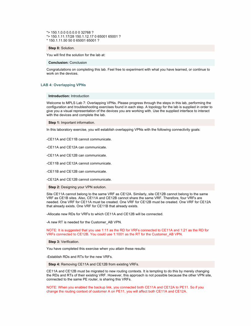
Step 8: Solution.
You will find the solution for the lab at:
Conclusion: Conclusion
Congratulations on completing this lab. Feel free to experiment with what you have learned, or continue to work on the devices.
LAB 4: Overlapping VPNs
Introduction: Introduction
Welcome to MPLS Lab 7: Overlapping VPNs. Please progress through the steps in this lab, performing the configuration and troubleshooting exercises found in each step. A topology for the lab is supplied in order to give you a visual representation of the devices you are working with. Use the supplied interface to interact with the devices and complete the lab.
Step 1: Important information.
In this laboratory exercise, you will establish overlapping VPNs with the following connectivity goals:
-CE11A and CE11B cannot communicate. -CE11A and CE12A can communicate. -CE11A and CE12B can communicate. -CE11B and CE12A cannot communicate. -CE11B and CE12B can communicate. -CE12A and CE12B cannot communicate.
Step 2: Designing your VPN solution.
Site CE11A cannot belong to the same VRF as CE12A. Similarly, site CE12B cannot belong to the same VRF as CE1B sites. Also, CE11A and CE12B cannot share the same VRF. Therefore, four VRFs are needed. One VRF for CE11A must be created. One VRF for CE12B must be created. One VRF for CE12A that already exists. One VRF for CE11B that already exists. -Allocate new RDs for VRFs to which CE11A and CE12B will be connected. -A new RT is needed for the Customer_AB VPN. NOTE: It is suggested that you use 1:11 as the RD for VRFs connected to CE11A and 1:21 as the RD for VRFs connected to CE12B. You could use 1:1001 as the RT for the Customer_AB VPN.
Step 3: Verification.
You have completed this exercise when you attain these results: -Establish RDs and RTs for the new VRFs.
Step 4: Removing CE11A and CE12B from existing VRFs.
CE11A and CE12B must be migrated to new routing contexts. It is tempting to do this by merely changing the RDs and RTs of their existing VRF. However, this approach is not possible because the other VPN site, connected to the same PE router, is sharing this VRFs. NOTE: When you enabled the backup link, you connected both CE11A and CE12A to PE11. So if you change the routing context of customer A on PE11, you will affect both CE11A and CE12A.

Sites CE11A and CE12B have to be migrated to new VRFs. All the references to them must be removed from the existing routing protocol contexts. In this task, you will remove the references to CE11A and CE12B. -Remove the existing address family BGP neighbor peering between CE11A and CE12B on their PE router. -Check any other references to CE11A and CE12B in their PE router configuration and, if required, remove them.
Step 5: Verification.
You have completed this exercise when you attain these results: -On the PE router, verify that the interface toward the CE router is no longer in the original VRF by using the show ip vrf interfaces command. This action should result in a printout similar to the one here:
PE11#sh ip vrf int Interface IP-Address VRF Protocol Serial0/0.113 150.1.11.50 Customer_A up Serial0/0.102 150.1.11.34 Customer_B up PE12#sh ip vrf int Interface IP-Address VRF Protocol Serial0/0.101 150.1.12.18 Customer_A up Serial0/0.113 150.1.12.50 Customer_B up -Verify the BGP neighbor relationship has been removed on the PE router with the show ip bgp vpnv4 vrf summary command. This action should give you a printout similar to the one here. Check the status of CE11A and CE12B in the printout.
PE11#sh ip bgp vpnv4 vrf Customer_A sum BGP router identifier 192.168.1.17, local AS number 65001 BGP table version is 68, main routing table version 68 3 network entries using 363 bytes of memory 3 path entries using 192 bytes of memory 4 BGP path attribute entries using 300 bytes of memory 2 BGP AS-PATH entries using 48 bytes of memory 3 BGP extended community entries using 72 bytes of memory 0 BGP route-map cache entries using 0 bytes of memory 0 BGP filter-list cache entries using 0 bytes of memory BGP using 975 total bytes of memory BGP activity 22/9 prefixes, 28/18 paths, scan interval 15 secs
Neighbor V AS MsgRcvd MsgSent TblVer InQ OutQ Up/Down State/PfxRcd
150.1.11.17 4 65011 49 53 0 0 0 00:04:17 Idle
PE12#sh ip bgp vpnv4 vrf Customer_B sum BGP router identifier 192.168.1.33, local AS number 65001 BGP table version is 33, main routing table version 33 5 network entries using 605 bytes of memory 7 path entries using 448 bytes of memory 7 BGP path attribute entries using pop0 bytes of memory 1 BGP rrinfo entries using 24 bytes of memory 2 BGP AS-PATH entries using 48 bytes of memory 4 BGP extended community entries using 96 bytes of memory 0 BGP route-map cache entries using 0 bytes of memory 0 BGP filter-list cache entries using 0 bytes of memory BGP using 16pop total bytes of memory BGP activity 122/102 prefixes, 160/138 paths, scan interval 15 secs

Neighbor V AS MsgRcvd MsgSent TblVer InQ OutQ Up/Down State/PfxRcd 150.1.12.49 4 65001 1477 1479 33 0 0 00:30:26 2
Step 6: Configuring new VRFs for CE11A and CE12B.
In this task, you will create the new VRFs for CE11A and CE12B. -Create the new VRFs for CE11A (A_Central) and CE12B (B_Central) on their PE router with the ip vrf command. -Assign new RDs to the newly created VRFs with the rd command. -Assign proper import and export RTs to the newly created VRFs with the route-target command. -Re-establish BGP routing between the PE routers and the CE routers. Please refer to the "Running BGP Between PE and CE Routers" lab if you need more details.
Step 7: Verification.
You have completed this exercise when you attain these results:
-On the PE router, verify that the interface toward the CE router is in the proper VRF by using the show ip vrf interfaces command. This action should result in a printout similar to the one here: PE11#sh ip vrf int Interface IP-Address VRF Protocol Serial0/0.113 150.1.11.50 Customer_A up Serial0/0.101 150.1.11.18 A_Central up Serial0/0.102 150.1.11.34 Customer_B up PE12#sh ip vrf int Interface IP-Address VRF Protocol Serial0/0.101 150.1.12.18 Customer_A up Serial0/0.102 150.1.12.34 B_Central up Serial0/0.113 150.1.12.50 Customer_B up -Verify the BGP neighbors on the PE router with the show ip bgp vpnv4 vrf summary command. This should give you a printout similar to the one here. Check the status of CE11A and CE12B in the printout.
PE11#sh ip bgp vpnv4 vrf A_Central sum BGP router identifier 192.168.1.17, local AS number 65001 BGP table version is 49, main routing table version 49 10 network entries using 1210 bytes of memory 10 path entries using 640 bytes of memory 7 BGP path attribute entries using 10 bytes of memory 1 BGP rrinfo entries using 24 bytes of memory 2 BGP AS-PATH entries using 48 bytes of memory 4 BGP extended community entries using 96 bytes of memory 0 BGP route-map cache entries using 0 bytes of memory 0 BGP filter-list cache entries using 0 bytes of memory BGP using 2438 total bytes of memory BGP activity 57/35 prefixes, 75/49 paths, scan interval 15 secs Neighbor V AS MsgRcvd MsgSent TblVer InQ OutQ Up/Down State/PfxRcd 150.1.11.17 4 65011 53 54 49 0 0 00:48:11 3 PE12#sh ip bgp vpnv4 vrf B_Central sum BGP router identifier 192.168.wg.33, local AS number 65001 BGP table version is 56, main routing table version 56 8 network entries using 968 bytes of memory 8 path entries using 512 bytes of memory 7 BGP path attribute entries using pop0 bytes of memory 1 BGP rrinfo entries using 24 bytes of memory 2 BGP AS-PATH entries using 48 bytes of memory 4 BGP extended community entries using 96 bytes of memory

0 BGP route-map cache entries using 0 bytes of memory 0 BGP filter-list cache entries using 0 bytes of memory BGP using 2068 total bytes of memory BGP activity 130/110 prefixes, 168/146 paths, scan interval 15 secs Neighbor V AS MsgRcvd MsgSent TblVer InQ OutQ Up/Down State/PfxRcd 150.1.12.33 4 65012 9 10 56 0 0 00:04:17 3 -Check the BGP routing table in the new VRF with the show ip bgp vpnv4 vrf command. You should see routes from CE11A or CE12B as well as routes imported from other VRFs. Use the AS path to work out which routes belong to which CE router. Routes announced by CE11A should have 65011 in the AS path, and routes announced by CE12B should have 65012 in the AS path. PE11#sh ip bgp vpnv4 vrf A_Central BGP table version is 49, local router ID is 192.168.1.17 Status codes: s suppressed, d damped, h history, * valid, > best, i - internal, r RIB-failure, S Stale Origin codes: i - IGP, e - EGP, ? - incomplete Network Next Hop Metric LocPrf Weight Path Route Distinguisher: 11:1 (default for vrf A_Central) *> 10.1.11.16/28 150.1.11.17 0 0 65011 ? *> 10.1.11.49/32 150.1.11.17 0 0 65011 ? *>i10.1.12.16/28 192.168.1.33 0 100 0 65012 ? *>i10.1.12.49/32 192.168.1.33 0 100 0 65012 ? *>i10.2.12.16/28 192.168.1.33 0 100 0 65012 ? *>i10.2.12.49/32 192.168.1.33 0 100 0 65012 ? r> 150.1.11.16/28 150.1.11.17 0 0 65011 ? *>i150.1.11.48/28 192.168.1.33 0 100 0 65011 ? *>i150.1.12.16/28 192.168.1.33 0 100 0 65011 ? *>i150.1.12.32/28 192.168.1.33 0 100 0 65011 ? PE12#sh ip bgp vpnv4 vrf B_Central BGP table version is 56, local router ID is 192.168.1.33 Status codes: s suppressed, d damped, h history, * valid, > best, i - internal, r RIB-failure, S Stale Origin codes: i - IGP, e - EGP, ? - incomplete Network Next Hop Metric LocPrf Weight Path Route Distinguisher: 12:1 (default for vrf B_Central) *>i10.0.0.0 192.168.1.17 0 100 0 65011 ? *>i10.1.11.16/28 192.168.1.17 0 100 0 65011 ? *>i10.1.11.49/32 192.168.1.17 0 100 0 6500wg ? *> 10.2.12.16/28 150.1.11.33 0 0 65012 ? *> 10.2.12.49/32 150.1.11.33 0 0 65012 ? *>i150.1.0.0 192.168.1.17 0 100 0 65011 ? *>i150.1.11.16/28 192.168.1.17 0 100 0 65011 ? r> 150.1.11.32/28 150.1.11.33 0 0 65011 ? -Use the show ip bgp vpnv4 vrf name prefix command to display details of an individual route and verify that the proper RTs are attached to the route. Your printout should be similar to the one here: PE11#sh ip bgp vpnv4 vrf Customer_B 10.2.12.49 BGP routing table entry for pop:1:10.2.pop.49/32, version 53 Paths: (1 available, best #1, table Customer_AB) Advertised to non peer-group peers: 150.1.11.33 65012 192.168.1.33 from 192.168.1.33 (192.168.1.33) Origin incomplete, metric 0, localpref 100, valid, external, best Extended Community: RT:1:23 RT:1:1001 PE12#sh ip bgp vpnv4 vrf Customer_A 10.1.11.49 BGP routing table entry for 1:10:10.1.11.16/28, version 23 Paths: (1 available, best #1, table Customer_A) Advertised to non peer-group peers:

150.1.12.17 65011 150.1.12.17 from 150.1.12.17 (10.1.11.49) Origin incomplete, metric 0, localpref 100, valid, external, best Extended Community: RT:1:10 RT:1:1001 -Connect to CE11A and perform ping and trace to the loopback address of CE12B (or vice versa). The other router should be reachable, and then test in the other direction. CE11A#ping 10.2.12.49 Type escape sequence to abort. Sending 5, 100-byte ICMP Echos to 10.2.12.49, timeout is 2 seconds: !!!!! Success rate is 100 percent (5/5), round-trip min/avg/max = 148/148/149 ms CE11A#trace 10.2.12.49 Type escape sequence to abort. Tracing the route to 10.1.pop.49 1 150.1.11.18 16 msec 16 msec 12 msec 2 150.1.12.33 [AS 65012] 72 msec 76 msec * CE12B#ping 10.1.11.49 Type escape sequence to abort. Sending 5, 100-byte ICMP Echos to 10.1.11.49, timeout is 2 seconds: !!!!! Success rate is 100 percent (5/5), round-trip min/avg/max = 148/148/149 ms CE12B#trace 10.1.11.49 Type escape sequence to abort. Tracing the route to 10.2.pop.49 1 150.1.12.34 16 msec 16 msec 12 msec 2 150.1.11.17 [AS 65011] 72 msec 77 msec * -Connect to CE12A and try to ping CE12B or CE11B. Those routers should not be reachable from CE11A, and then ping CE11A and CE12A from CE11B.
CE12A#ping 10.2.12.49 Type escape sequence to abort. Sending 5, 100-byte ICMP Echos to 10.2.pop.49, timeout is 2 seconds: ..... Success rate is 0 percent (0/5) CE11B#ping 10.2.12.49 Type escape sequence to abort. Sending 5, 100-byte ICMP Echos to 10.2.12.49, timeout is 2 seconds: ..... Success rate is 0 percent (0/5)
Step 8: Solution.
The solution to this lab can be found at:
Conclusion: Conclusion
Congratulations on completing this lab. Feel free to experiment with what you have learned, or continue to work on the devices.
