david s. watson portfolio
TRANSCRIPT
A1
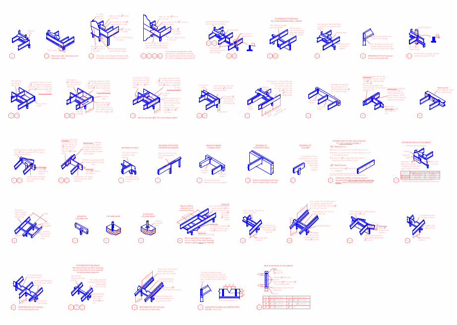
Blockingpanel
A2 Must have 1
3
4
" minimum joist
bearing at ends
TJI® rim joist
114" Trus Joistrim board
Toe nail - 10d (3") box at6" on-center
2x_ studwall at 16"on-center
12"min.
A3.4
Boundary nailing -8d (212") common at4" on-center*
*See Trus Joist Framer's Pocket Guide
for additional installation specifications.
Plate nail - 16d (312") box at12" on-center
Floor panel nail - 8d (212")common at 6" on-center
Install proper blocking tosupport all panel edges
Toe nail - 10d (3") box at6" on-center*
Floor panel nail - 8d (212") commonat 6" on-center*
Plate nail - 16d (312") box at16" on-center*
*Conventional construction code
minimum for use with A3 only. See
Trus Joist Framer's Pocket Guide for
A3.1-A3.3 installation specifications.
1" or 114"Trus Joistrim board*
A3.1
Remove tongue and groove fromfloor panel edges supported by 1"e-Rim® to ensure quality nailing.
A3 A3.3A3.2
Web stiffenersrequired each side atB1W and B2W
B1
B2 B2W
B1W
Load bearing or shear wall above(must stack over wall below)
2x4 minimumsquash blocks
116"
Blocking panel
B3WB3
below-see detail B1
may be required withshear walls above or
Blocking panelsWeb stiffeners requiredeach side at B3W
INTERMEDIATE BEARING
NO LOAD BEARING WALL ABOVE
Blocking panel
End of joists atcenterline ofsupport
B4
Load bearing or shear wall above(must stack over wall below whenpresent)
BC
Beveled web stiffener eachside of TJI® joist web
TJI® joist flange must bear fullyon plate. Birdsmouth cut mustnot overhang inside face of plate.
BIRDSMOUTH CUT allowed
at low end of joist only
CS
116"
Use 2x4 minimum squash blocks totransfer load around TJI® joist
2x4 minimumsquash blocks
Load from above
E1 E1W
Trus Joist rimboard
Web stiffenersrequired eachside at E1W
8" diameter maximum hole for117
8" - 20" deep blocking panels;6" diameter maximum for blocking
panels 912" deep or shorter than12" long.
Do not cut flanges.
E3E2
4'-0" length of34" reinforcement onone side at E2, bothsides at E3
Face grainhorizontal
Attach reinforcementto joist with 8d (212")common nails at 6" on-center. When reinforcingboth sides, stagger nails.
2'-0"
maximum
Trus Joist rimboard
8" diameter maximum hole for117
8" - 16" deep blocking panels;6" diameter maximum for blocking
panels 912" deep or shorter than12" long.
Do not cut flanges.
E4
Attach reinforcement tojoist web with 3 rows10d (3") common nailsat 6" on-center,clinched. Use 2 rowswith 912" and 1178"TJI® joists.
6'-0" length of TJI® joistreinforcement and fillerblock. Use 4'-0" lengthwith 912" and 1178" TJI®joists.
Not for use with 3
1
2
" TJI
®
joist flange widths
2'-0"
maximum
8" diameter maximum hole for117
8" - 16" deep blocking panels;6" diameter maximum for blocking
panels 912" deep or shorter than12" long.
Do not cut flanges.
Trus Joist rimboard
E5 E6
12" length of 34"reinforcement onone side at E5,both sides at E6
Attach reinforcement to joistwith one 8d (212") commonnail at each corner
Less than 5"
Trus Joist rimboard
F1
Nail through 2x_, wood backer andTJI® joist web with 2 rows 10d
(3") common nails at 6"on-center, clinched. Use
16d (312") nails with312" TJI® joistflange widths.
Blockingpanel
Woodbacker
11 2 times
cantilever
length
4'-0"
maximum
cantilever
(uniform loads only)
H1
Top flangehanger
Web stiffeners required ifsides of hanger do notlaterally support at least 3
8"of TJI® joist top flange
Face mounthanger
H2
Backer block: Install tightto top flange (tight tobottom flange with facemount hangers). Attachwith ten 10d (3") box nails,clinched when possible.
Filler block: Attach with ten 10d(3") box nails, clinched. Use ten16d (312") box nails from eachside with 312"TJI® joist flange widths. Usefifteen nails with TJI® joist depthsgreater than 16".
Backer blockboth sides of webwith single TJI®
joistH3
Bearing plate:Flush plate with insideface of wall or beam
Variable slope joist hanger.Verify capacity and depthlimitations.
LSTA24 (Simpson or USP) strap with twelve10d x 112" nails required at H5S with slopesgreater than 3" per foot
H5 H5S
Strap nails:Leave 238"minimum enddistance
Filler block: Attach withten 10d (3") box nails,clinched. Use ten 16d(31
2") box nails fromeach side for TJI®
joists with 312" flangewidths.
H6 SH6
Backer block: Install tightto bottom flange (tight totop flange with top flangehangers). Attach with ten10d (3") box nails, clinchedwhen possible.
LSTA18 strap required at H6Swith slopes greater than 3" per
foot
Strap nails:Leave 238" minimumend distance
Variable slope joist hanger.Verify capacity and depthlimitations. L1
Trus Joist rim board orblocking for lateralsupport
Parallam® PSL orTimberStrand® LSLColumn
BEARING AT WALL
L2
Strap per code if top plateis not continuous overheader
BEARING FOR DOOR
OR WINDOW HEADER
L3
BEAM TO BEAM
CONNECTION
Top flangehanger
Face mounthanger
See current Trus Joistliterature for framing connectors
L4
BEARING AT
CONCRETE WALL
Protect untreated wood from
direct contact with concrete
L5
BEARING AT
COLUMN
Verify Parallam® PSL orTimberStrand® LSL column
capacity and beambearing length.
See currentTrus Joistliterature.
(1) Load must be applied evenly across entire
beam width. Otherwise, use connections for side-loaded beams.
If using 12d (314") or larger nails, the number ofnailing rows may be reduced by one.
Minimum of 4 rows 10d (3" x 0.128") nails at 12" o.c. for14" and deeper beams
Minimum of 3 rows 10d (3" x 0.128") nails at 12" o.c.
Additional nailing or bolting may be
required with side-loaded multiple-member
beams. Refer to current product literature.
CONNECTION OF MULTIPLE PIECES
OF TOP-LOADED BEAMS
(1)
Minimum of 2 rows 12" bolts at 24"o.c. staggered
3
1
2
" Width Pieces:
L6
1
3
4
" Width Pieces:
LA
Trus Joistrim board
See fastenertable below. Maintain2" distance (minimum) fromedge of ledger to fastener.
Treated 2x_ledger
Flashing
Structural exterior sheathingEXTERIOR DECK ATTACHMENT
1
1
4
" rim board
Fastener
Allowable load determined in accordance with AC 124.
Corrosion-resistant fasteners required for wet-service applications.
1" e-Rim
™
3
8
" lag bolt
1
2
" lag bolt475 / 750
400 / 630 N.A. / N.A.
325 / N.A.
Allowable Load / Factored Resistance (lbs)
L
O
L
Double joistmay be requiredwhen L exceedsjoist spacing
2x_ overhang.Notch aroundTJI® joist topflange.
Blockingas required
End wall
LLC Wall
P1
BEAM ON
COLUMN CAP
P2
COLUMN BASE
P3
ELEVATED
COLUMN BASE
Optionalnon-shrinkgrout
PB1When specified on the layout,
one or more of the three bracing
options shown must be installed
1 3 joist span
8' max.
Option #1:TJI® Joist blocking with end
blocks installed at 13 joistspan locations using
two 8d (212")box nails or212" screws,
typical
Option #2:2x_ strapping installed at 1
3joist span locations usingtwo 212" screws per joist
Apply subfloor
adhesive to all
contact surfaces
Option #3:directly applied ceiling
R1
Shear blocking- Trus Joist rimboard or TJI® joist
Beveled bearingplate required whenslope exceeds 14"
per foot
13 adjacent span
maximum R10
Shear blocking- Trus Joist rimboard or TJI® joist
2x4 one side. Use 2x4 both sides ifjoist spacing is greater than 24"on-center. Attach with 2 rows 8d (212")box nails at 8" on-center.
Beveledbearing plate
required when slopeexceeds 14" per foot
Beveled 2x4 block
Filler
4'-0"
minimum
2'-0"
maximum
R14
Strap nails:Leave 238"minimum enddistance
Double beveled bearingplate when slope exceeds14" per foot
LSTA18 (Simpson or USP) strap withtwelve 10d x 11
2" nails
R3
Variable slopeseat connector
V-cut shear blocking-Trus Joist rim board
13 adjacent span
maximum
R5
V-cut shear blocking-Trus Joist rim board
Beveled web stiffeners onboth sides. Cut to matchroof slope.
2x4 block forsoffit support
BIRDSMOUTH CUT allowed
at low end of joist only
2'-0"
maximum
WR7R7
Web stiffenersrequired each sideat R7W
Beveled bearingplate requiredwhen slopeexceeds 14" perfoot
INTERMEDIATE BEARING
Blocking panels or shear blocking
may be specified for joist stability
at intermediate supports
R7S
Twist strap and backerblock required at R7S with
slopes greaterthan 3" per foot
R8
2x4 one side. Use 2x4 bothsides if joist spacing isgreater than 24" on-center.
2 rows 8d (212")box nails at 8" on-center
Beveled 2x4 block withbeveled web stiffener onopposite side of web
V-cut shear blocking-Trus Joist rim board
BIRDSMOUTH CUT allowed
at low end of joist only
4'-0"
minimum
2'-0"
maximum
SB
Trus Joist rim board for shearblocking (between joists). Field trimto match joist depth at outer edge ofwall or locate on wall to match joistdepth.
13
13
13
12
12
SHEAR BLOCKING and VENTILATION
HOLES...Roof Only
Maximum allowable V-cut
W
W
Three 8d (212") box nails,clinched(Three 16d (31
2") box nails at 312"
TJI® joist flange widths)
Web stiffener each side. Seesizes below.
Gap:18" minimum
234" maximum
WEB STIFFENER ATTACHMENT
112"
112"
Tight fit
212"
W
312"
2516"
34" x 2516" minimum2116"
Web Stiffener Size
58" x 2516" minimum
12" x 2516" minimum112"134"
W
2x4
78" x 2516" minimum
1" x 2516" minimum
Web Stiffener Size
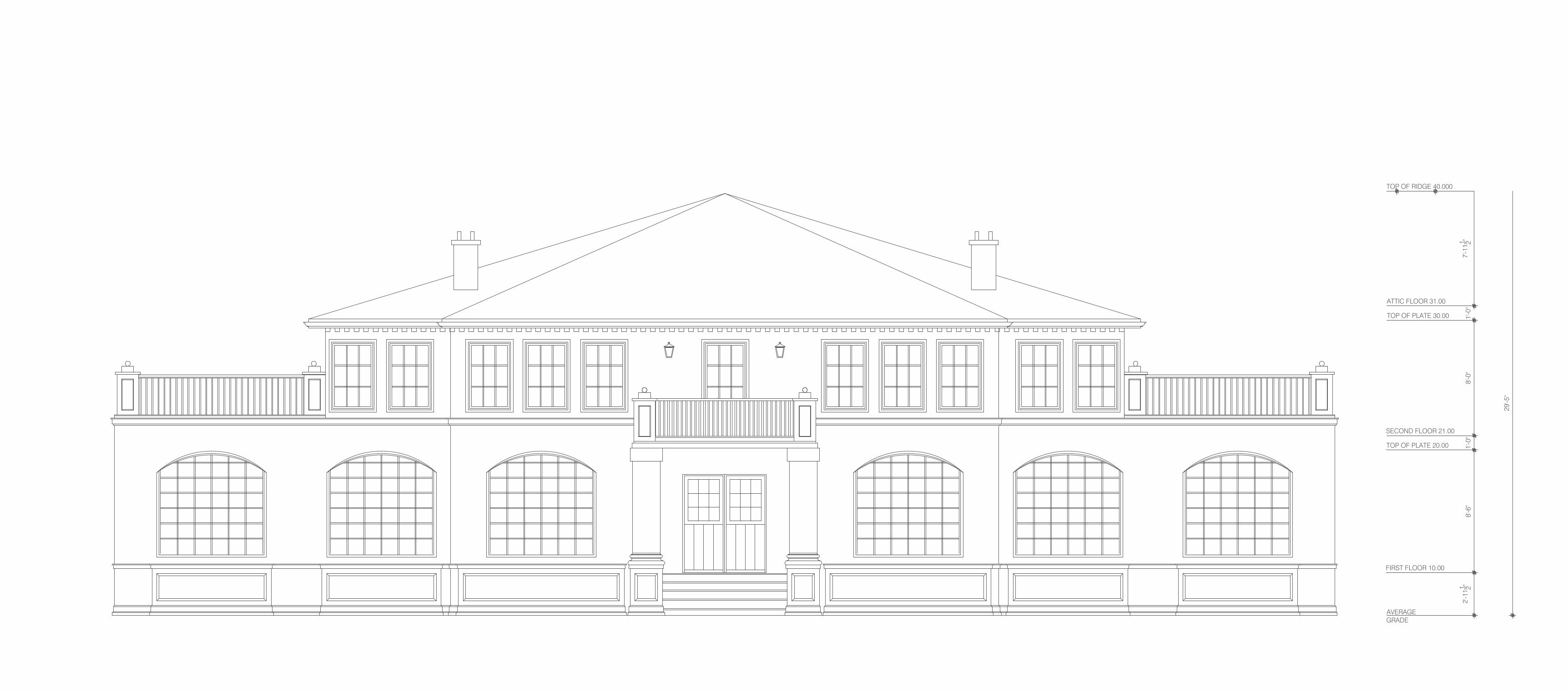
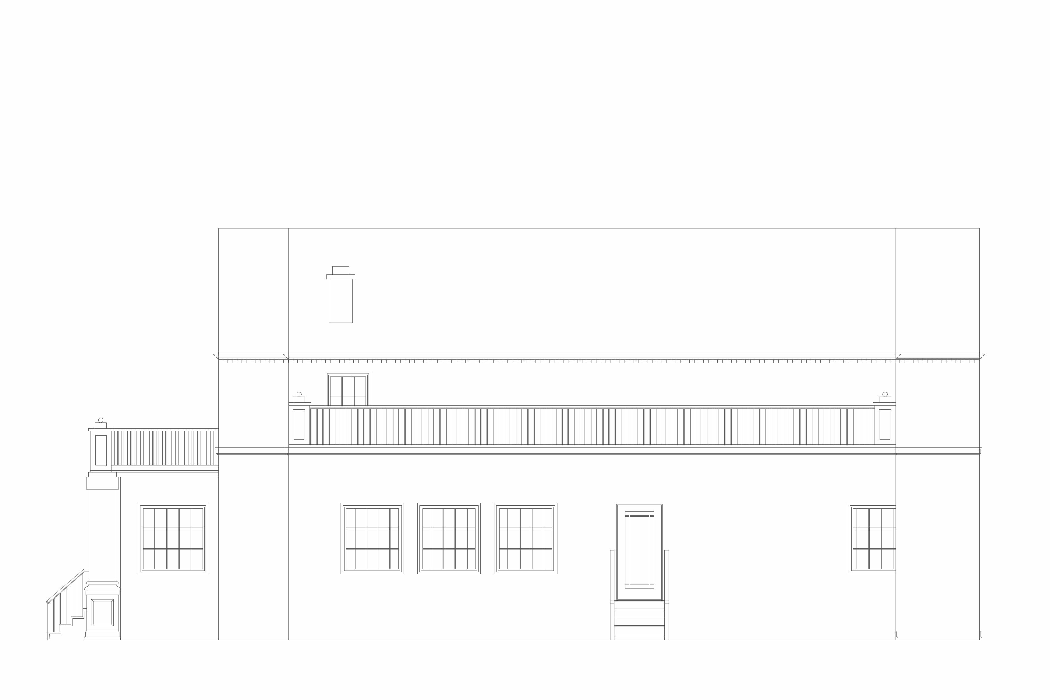
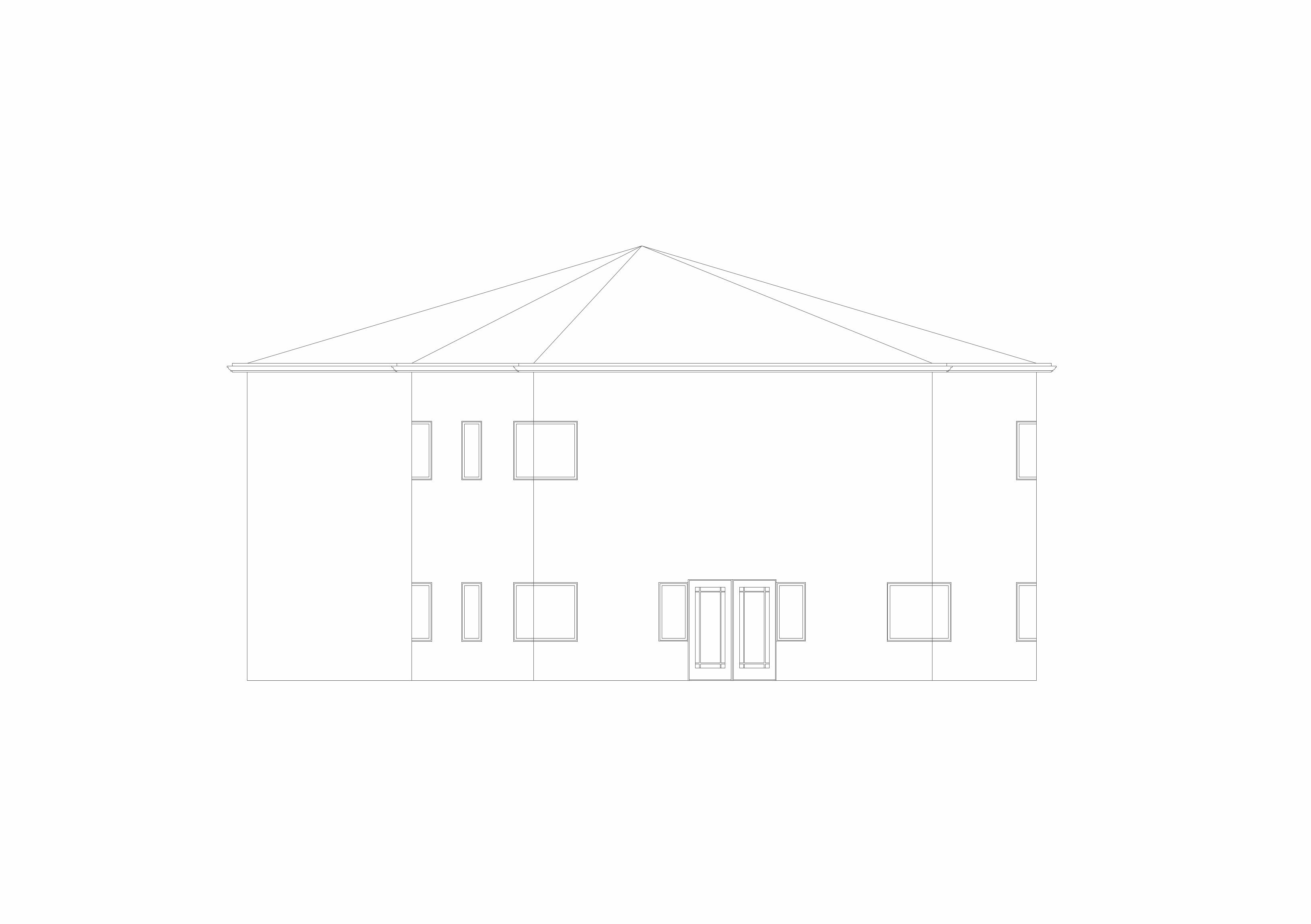
AVERAGEGRADE
TOP OF PLATE 30.00
ATTIC FLOOR 31.00
TOP OF RIDGE 40.000
TOP OF PLATE 20.00
FIRST FLOOR 10.00
2'-1
11 2"8'
-6"
1'-0
"8'
-0"
1'-0
"7'
-111 2"
29'-5
"
SECOND FLOOR 21.00
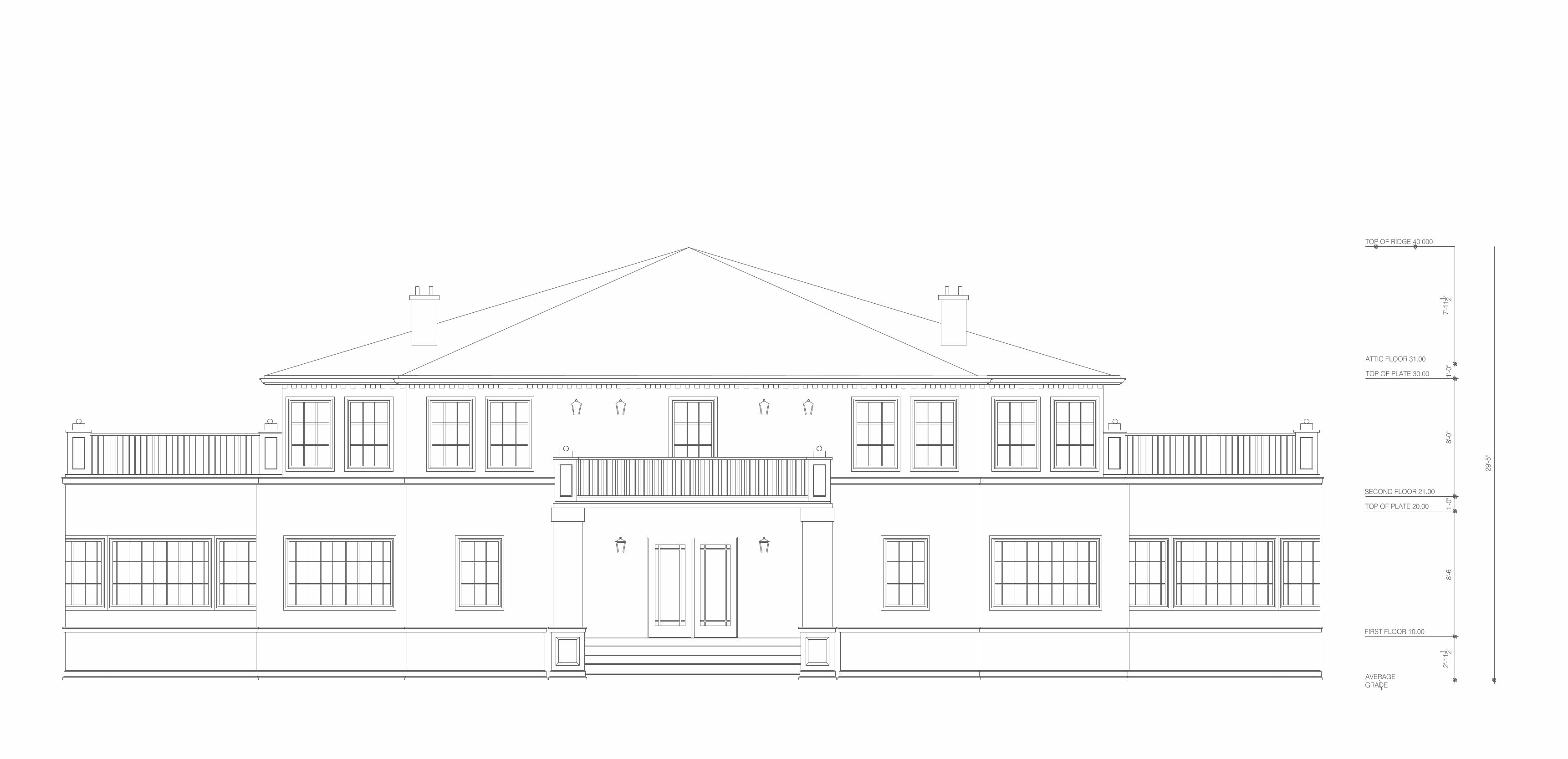
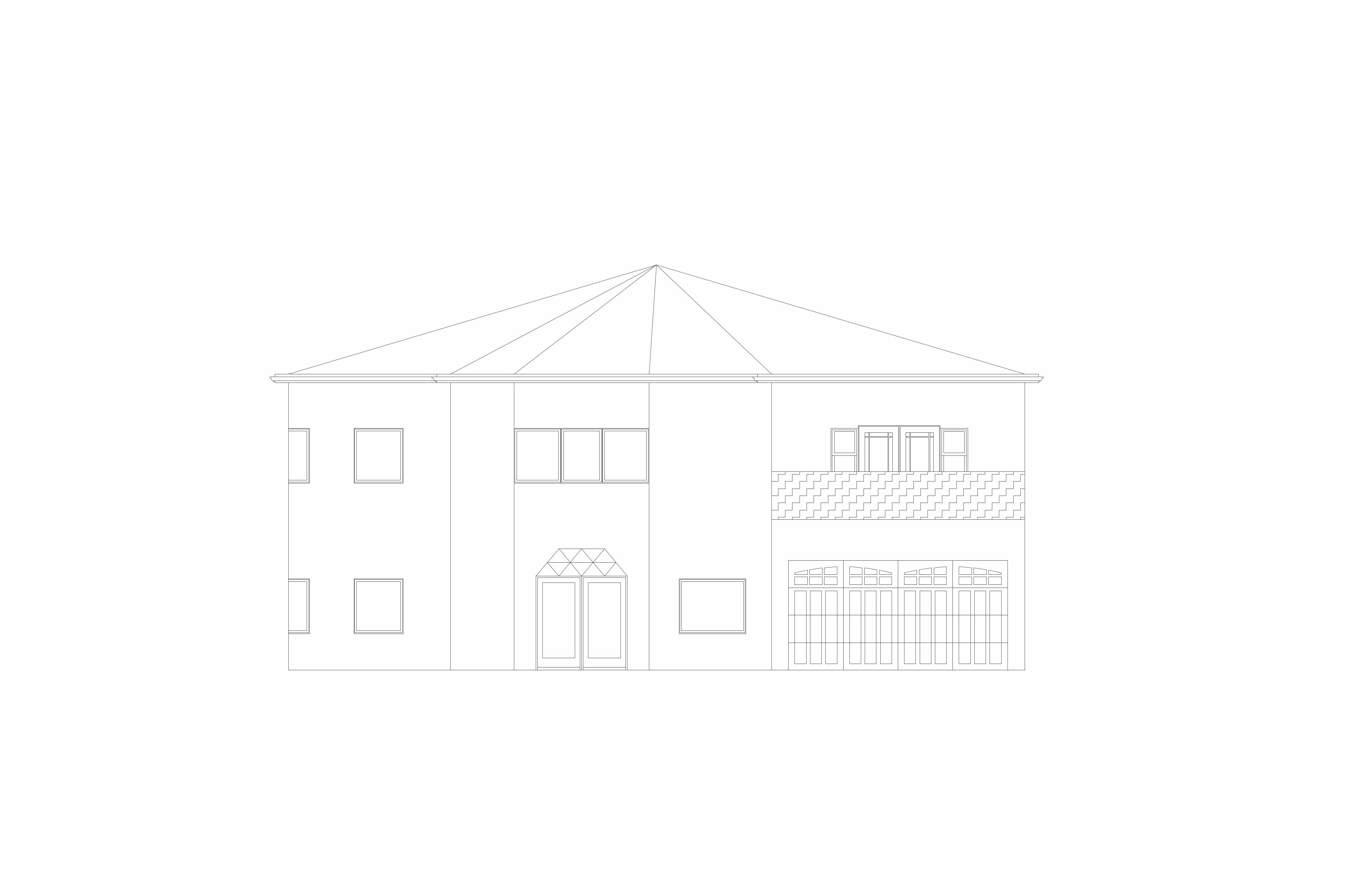
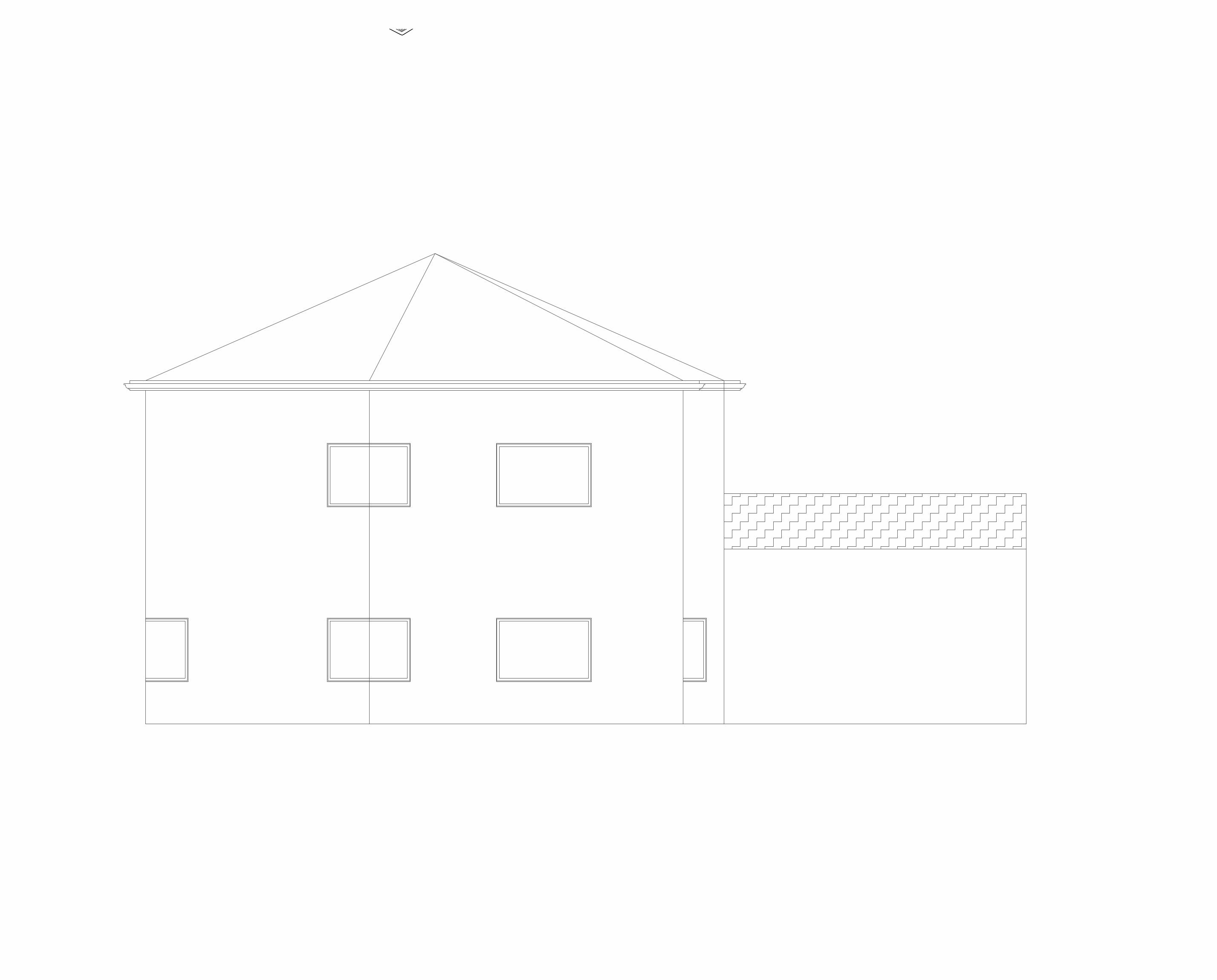
AVERAGEGRADE
TOP OF PLATE 30.00
ATTIC FLOOR 31.00
TOP OF RIDGE 40.000
TOP OF PLATE 20.00
FIRST FLOOR 10.00
2'-1
11 2"8'
-6"
1'-0
"8'
-0"
1'-0
"7'
-111 2"
29'-5
"
SECOND FLOOR 21.00