dauphin island bridge - pci€¦ · dauphin island bridge presents the major design/construction...
TRANSCRIPT

Design/Construction Feature
Dauphin Island Bridge
Presents the major design/construction highlights of
the Dauphin Island Bridge—a 17,814-ft (5430 m) long
prestressed concrete structure located near Mobile,
Alabama. The bridge, which utilized precast concrete
in many innovative ways, was built using four distinct
construction techniques and was completed on
schedule within 2 years at a total bid price of $43 per sq
ft ($463 per m2).
Mobile - 50 miles f
//
Bayou Le Satre
r7Alabama Port
' Cedar Pt.
OP
Dauphin Island
Gulf of Mexico
Fig. 1. Location of Dauphin Island Bridge.The original structure was destroyed by ahurricane in September 1979.
Acombination of several constructiontechniques was used advanta-
geously to build the superstructure of thenew 17,814-ft (5430 m) long Dauphin Is-land Bridge. The structure links DauphinIsland in the Gulf of Mexico to CedarPoint about 50 miles (80 km) south ofMobile, Alabama (see map, Fig. 1).
The various construction methods in-cluded:
1. Precast segmental balanced can-tilever erection.
2. Precast segmental span-by-spanerection.
3. Precast girder/deck monolithic spanconstruction.
4. Standard precast girders with cast-in-place deck construction.
This article focuses primarily on theprecast segmental aspects of the project.
The bridge combines 13,924 ft (4240 m)of precast prestressed concrete full-decktrestle spans with high-level precast seg-mental concrete bridge spans. The seg-mental portion is composed of 26 118-ft (36
126

3T
x ^
Fig. 2. Panoramic view of Dauphin Island Bridge showing the high-level central andapproach spans. Entire structure was built within 2 years.
m) approach spans (using 160 uniform • In the approach spans, up to 90 ft (27depth box girder segments) and a three-span 822-ft (250 m) unit (employing 92variable depth segments). Construction ofthe approaches was by the span-by-spanmethod on temporary trusses and of themain span and two side spans by the bal-anced cantilever method.
A panoramic view of the completedbridge is shown in Fig. 2.
The following major features were in-corporated into the structure:
• The 400-ft (122 m) main navigationalspan is of variable depth and one ofthe longest precast segmental bridgespans in the world.
• The 822-ft (250 m) main span unit isepoxy jointed. Traffic rides on theas-cast surfaces in both main and ap-proach spans.
• External post-tensioning tendons in-side the box girder segments wereused for the high-level approacheswithout using epoxy in the match-cast joints.
m) high precast hollow box pierswere match-cast and post-tensionedvertically.
• Multiple shear keys were used for allthe precast segments.
The original Dauphin Island Bridge wasbuilt in 1955 and was destroyed by Hur-ricane Frederick in September 1979. As aresult, residents of the island were physi-cally cut off from the mainland, deprivingthem of regular supplies and emergencyhealth services. Ferry service from themainland to the island was established as atemporary solution, but despite this ser-vice there was an urgent need to build areplacement bridge.
Therefore, on October 10, 1979 the con-sulting firm of Figg and Muller Engineers,Inc. was commissioned to design a newbridge, with a limited time to prepare adesign for the entire structure in segmentalconcrete which could be constructedwithin 2 years.
Simultaneously, the Alabama Highway
PCI JOURNAL,,January-February 1984 129

Fig. 3. Dauphin Island Bridge in service. The center span is 400 ft (122 m) with a verticalclearance of 85 ft (26 m) to allow small ships and sea craft to pass. The two side spansare 211 ft (64.4 m).
Department Bridge Bureau was to preparealternate designs.
Finished drawings and specificationswere completed in December 1979. A pre-bid conference was held the followingmonth and bids were received in February1980. The main contract was awarded toBrown and Root, Inc., for $32 million.
The contract included the 822-ft (251 m)main segmental unit with a 400-ft (120 m)center span, which has an 85-ft (26 m)vertical clearance over the Gulf Intra-coastal Waterway. This feature allowssmall ships to pass under the main spansafely. To protect the bridge piers frompossible collisions with errant ships, suit-able bulkheads were built adjacent to thepiers (see Fig. 3).
Because the bridge is located in an eco-logically sensitive area, special care wastaken during construction to work withinstrict environmental restraints.
In planning the bridge, the engineersraised its elevation 23 ft (7 m) and designedthe structure for winds up to 200 miles perhour (330 km/hr), thereby increasing itsresistance to potential hurricanes. The en-tire design and construction process forthe Dauphin Island Bridge was engineeredto meet the needs of the emergency situa-tion caused by the 1979 hurricane.
The main span of the bridge was erectedas a balanced cantilever made up of vari-ous depth precast single-cell box seg-ments. For the approach spans, the span-by-span erection method, used so suc-cessfully on the Florida Keys bridges, wasemployed.
Figs. 3 and 4 show various views of thecompleted bridge. Fig. 5 is a cutaway sec-tion of the bridge at the start of the 400-ft(120 m) main span. Shown on the diagramare some of the major features of the con-struction method.
130

•71Fig. 4. Bird's eye view of bridge. The overall span is 17,814 ft (5430 m).
RIDING ON AS-CAST SURFACE(FIRST FOR BALANCED CANTILEVER CONSTRUCTION)
PIER DIAPHRAGMPOST-TENSIONING
PIER DIAPHRAGM
CANTILEVERPOST-TEN SION ING PRECAST
SEGMENT EP INMHEU CASTJO S
-TWIN WALL,i PIERSICAST-IN-PLACE)
MAIN PIERFOOT IN
Fig. 5. Cutaway section of bridge at start of 400-ft (122 m) main span, showing majorfeatures of construction method.
PCI JOURNALJJanUary-February 1984 131

C)N
in tirti-
Ga o"o Sal
y Dauphin Bay Chan nel{ Sta. 183 - 65.56
i Is
'Ulm
ml=imwN
End BridgeStd. 193 T 04.$6
LdtleL as A x Herons Dauphin
G.L. Grants Sta. 4-C.L. Aux Huitres Pass I Island\Sta. 21 +81.51 Jv"1C.L. Bridge,. 77+ 211
Peavey --iiiIsland
PLAN
dae Len g th = 17.814'Proposal'A'
95 • 65' = 6,175' -0"Monolithic Spans
P roposal '8'
Proposal C'
3.690'-0" 56@65' =3,640'0"58@65'=3770-0"
Segmental Monolithic Spans AASHTO Grd. SpansC.L Grants Pass
Aux Huitres Pass
EL. 23.0' W I 50' EL. 23.0'MLW. EL. 0.0 Min. CI.
C.L. Pass Aux Heronso ^ c^ m cSCALE IN FEET PROFILE
Fig. 6. Plan and profile of Dauphin Island Bridge. (Note: 1 ft = 0.305 m; 1 in. = 25.4 mm.)
C.L. Dauphin Bay Channel

F C.L. Pass Aux Herons
175'-0"f 175'-o"
Grants Pass
PNRan'.n•,
1 1534' -0"8 spans @ 118'-0" 7 Spans @ 118'-0" 211' 0 400'-0" 211 `-9' 7 5 ans 118'-0" fi Spans @ 118'-0
C.L. PassAux Herons
C.L. Grants Pass
C
ML W. Elev. (100' -C.L. Bridge 8Profile Grade DAUPHIN ISLAND
I ELEVATIONCROSS SECTION MAIN SPAN
(Looking Up Station)
Fig. 7. Plan and elevation of main span of Dauphin Island Bridge. (Note: 1 ft — 0.305 m; 1 in. = 25.4 mm.)WW
G

Fig. 8. Half section of variable depth box segments for 400-ft (122 m) main span ofDauphin Island Bridge. (Note: 1 ft = 0.305 m; 1 in. = 25.4 mm.)
Number and Size of Precast Segmental Components.
Approach Spans (Superstructure)156 typical segments, 42 ft 3 1/2 in. wide, 18 ft long, 7 ft deep, weighing 63 tonseach.
4 expansion joint segments, 42 ft 3 1/2 in. wide, 9 ft 6 in. long, 7 ft deep. weighing65 tons each.
24 pier segments, 42 ft 3 1/2 in. wide, 9 ft 6 in. long, 7 ft deep, weighing 65 tonseach.
Approach Spans (Substructure)
174 box pier segments. 16 ft x 8 ft. 9 ft high.
Cantilever Center Spans (Superstructure)
92 variable depth segments, 10 ft 3 1/2 in. long, 42 ft 3 1/2 in. wide, 21 ft 5 in. highto 7 ft; maximum segment weight: 150 tons.
Note: 1 ft = 0.305 m; 1 in. = 25.4 mm; 1 ton = 0.907 tonne.
134

Fig. 6 is a plan and profile of the entirebridge, while Fig. 7 is a plan and elevationof the main span of the bridge. Fig. 8shows a half section of the variable depthbox segments of the main span.
On each side of the main span are 13spans of 118 ft (36 m) each, which consistof a uniform depth, single-cell box madeup of precast segments that were erectedby the span-by-span method.
The table on the opposite page providesa summary of the total number and size ofprecast segmental components used inboth the substructure and superstructureof the bridge.
The balance of the bridge structure con-sists of 178 65-ft (19.8 m) spans made up ofmonolithically precast units of five gird-ers, a deck, and two safety shape para-pets {Fig. 9). These were supported onpiers consisting of two or three 54-in.(1372 mm) diameter precast cylinder pilesand precast pier caps (Fig. 10). In addi-tion, there are 37 spans constructed withAASHTO girders with cast-in-place deck.
The precast box segments, pier boxes,
t ^
Fig. 9. Monolithically precast 65-ft (19.8m) spans each consisted of five girders, adeck, and two safety shape parapets.These units weighed 270 tons (245tonnes) each.
and monolithic spans (Figs. 11 and 12) weremanufactured at a plant in Mandeville,Louisiana. A single casting machine wasused to precast the 80 segments necessaryfor the main spans. Control of productionhad to be particularly high because the
Fig. 10. A total of 178 65-ft (19.8 m) monolithically precast spans were used in thelow-level approaches of the bridge. The piers are made up of three 54-in. (1372 mm)diameter cylindrical precast piles and a precast cap.
PCI JOURNAL/January-February 1984 135

U
Fig. 11. Precast segment ready for match casting in forms at Mandeville plant. Notemultiple keys.
Fig. 12. Several variable depth, match-cast segments for main spans are being aircured prior to shipment to bridge site.
136

Fig. 13. Precast segments for 400 -ft (122 m) main span were barged 150 miles (240 km)to construction site.
cast surface was the final riding surface.This is the first precast segmental bridgeerected by balanced cantilever to specify afinished precast deck surface.
The segments were post-tensionedtransversely across the deck slab prior toshipment. All superstructure concrete was
specified for 5500 psi (38 MPa) at 28 days.Maximum segment weight was 90 tons (82tonnes).
The precast segments were barged 150miles (240 km) to the construction site (seeFig. 13).
Piers for the approach span segmental
Fig. 14. Pier segments for all precast segmental approach spans were precast. Thedimensions are 16 x 8 ft (4.88 x 2.44 m) with 10-in. (254 mm) thick walls.
PCI JOURNAL/January-February 1984 137

7Fig. 15. Workers platform, whichsurrounded the piers, was jacked up asthe pier progressed upward to provideaccess to joints where epoxy was used.
Fig. 16. The top segment of each piercontained rectangular blockouts tosupport the steel erection trusses forspan-by-span erection.
box portions of the bridge are made upof precast hollow-box segments up to 90ft (27.4 m) high. They are 16 x 8 ft(4.88 x 2.44 m) with 10-in. (254 mm) thickwalls and were cast and post-tensionedvertically with epoxy in the joints.
Figs. 14 through E6 show the variouserection stages of the pier segments.
The twin walled I-section piers werecast in place on a footing of prestressedconcrete cylinder piling. They are mo-ment-connected to the superstructure,thus allowing the balanced cantilevererection to continue without falsework.
After completion of the four precast andtwo cast-in-place segments of the piertable, the falsework was removed (Figs. 17and 18).
The erection of the main spans was ac-complished using the well-known bal-anced cantilever construction method. In
this technique pairs of box segments areprogressively erected on each side of apier (Fig. 19) for a half span. The sameprocedure is performed simultaneouslyon the adjacent pier until both segmentcantilevers reach midspan, where they arejoined by a closure strip.
Each box segment was held temporarilyin position (Fig. 20) with a barge-mountedcrane. Epoxy was applied to the match-cast faces (Fig. 21) and the joint wasclosed by stressing four post-tensioningbars (Fig. 22).
After each pair of segments waserected, permanent post-tensioning in theform of two or four 12 x '/-in. (12.7 mm)strand tendons was installed and stressedat anchorages located in the segmentwebs. The contractor erected two seg-ments in a 12-hour day (Fig. 20). Fig. 23shows an inside view of a completed box.
138

Fig. 17. Barge-mounted crane lifting pier
segment for main span. Note that mainpiers were twin walled.
IFig. 18. Pier segments, precast andcast-in-place, ready for adding precastbox segments.
Fig. 19. One of two main piers supporting balanced cantilever of precast box segments.
PCI JOURNAL/January-February 1984 139

Fig. 20. Barge-mounted crane lifting precast segment to attach to cantilever. Shallowdepth of box indicates span is nearly complete.
Fig. 21. Workmen coating faces of precast segments to insure good bond betweenmatch-cast segments. Note reinforcing bars along box edges for cast-in-place safetyshape parapet.
140

Fig. 22. Hydraulic jack being used to tension tendons for erection stresses.
Fig. 23. View inside box looking toward main span pier diaphragm. The variable depthof the box, 7 ft (2.13 m) at the midspan to 21 1/2 ft (6.56 m) at the piers, is noticeable.Empty space can be used for inspection purposes.
PCI JOURNAL January-February 1964 141
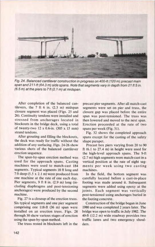
Fig. 24. Balanced cantilever construction in progress on 400-ft (120 m) precast mainspan and 21 1-ft (64.3 m) side spans. Note that segments vary in depth from 21 ft 5 in.(6.5 m) at the piers to 7 ft (2. 1 m) at midspan.
After completion of the balanced can-tilevers, the 7 ft 6 in. (2.3 m) midspanclosure segment was placed (Figs. 25 and26). Continuity tendons were installed andstressed from anchorages located inblockouts in the bridge deck, using a totalof twenty-two 12 x 0.6-in. (305 x 15 mm)strand tendons.
After grouting and filling the blockouts,the deck was ready for traffic without theaddition of any surfacing. Figs. 24-26 showvarious shots of the balanced cantilevererection sequence.
The span-by-span erection method wasused for the approach spans. Castingmachines were used to match-cast 184segments. Typical segments 18 ft long and7 ft deep (5.5 x 2.1 m) were produced fromone machine at the rate of one each day.Pier segments, 9 ft 8 in. (2.9 m) long (in-cluding diaphragms and post-tensioninganchorages) were produced by the secondmachine.
Fig. 27 is a closeup of the erection truss.Sbt typical segments and one pier segmentcomprising one 118-ft (36 m) span wereinstalled on an erection truss. Figs. 28through 30 show various stages of erectionusing the span-by-span method.
The truss rested in blockouts left in the
precast pier segments. After all match-castsegments were set on pier and truss, theclosure gap was placed before the entirespan was post-tensioned. The truss wasthen lowered and moved to the next span.Erection proceeded at the rate of twospans per week (Fig. 31).
Fig. 32 shows the completed approachspans except for the casting of the safetyshape parapet.
Precast box piers varying from 20 to 90ft (6.1 to 27.4 m) in height were used forthe high-level approach spans. The 9-ft(2.7 m) high segments were match-cast in avertical position at the rate of eight seg-ments per week using two castingmachines.
In the field, the bottom segment wascarefully located before a cast-in-placefooting was made around it. Subsequentsegments were added using epoxy at thejoints. Each segment was verticallypost-tensioned using anchorages buried inthe footing concrete.
Construction of the bridge began in June1980 and was completed 2 years later. Thebridge was open to traffic in July 1982. The40-ft (12.2 m) wide roadway provides twotraffic lanes and two emergency shoul-ders.
142

Fig. 25. Gap at centerline of main 400-ft (120 m) span ready for cast-in-place closure.Approximately two precast segments per 12-hour day were erected.
Fig. 26. Main spans almost complete. Structure is now ready for adjacent spans whichwere erected by span-by-span method.
PCI JOURNAL/January-February 1984 143
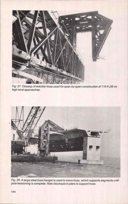
Fig. 27. Closeup of erection truss used for span-by-span construction of 118-ft (36 m)high level approa ches.
Fig. 28. A large steel truss hanger is used to move truss, which supports segments untilpost-tensioning is complete. Note blockouts in piers to support truss.
144

Fig. 29. Approach span with all segments in place on truss. After pier segment is placedthe final post-tensioning will be done and truss moved to next span.
Fig. 30. Placing precast segment on erection truss. All segments made with transversegrooves in deck with steel fines. No additional surfacing is necessary.
PCI JOURNALlJanuary-February 1984 145

Fig. 31. Large barge-mounted crane ready to move erection truss to next span.
Fig. 32. Approach spans complete and ready for casting the safety shape parapet, thelast step in erection procedure.
146

Fig. 33. Completed Dauphin Island Bridge silhouetted against the beautiful sunset.
Motorists using the bridge have ex-pressed satisfaction in the ease of drivingacross the span and the smooth ride overthe as-cast surface.
The total construction cost of the bridgewas $32 million. With the gross surfacearea estimated to be 750,000 sq ft (70000m2 ), the unit price amounted to approxi-mately $43 per sq ft ($463 per m 2 ). The unitbid prices for the precast segmental boxgirders were $115 per sq ft ($1238 per m2)for the main cantilevered spans and $55per sq ft ($592 per ml ) for the span-by-spanerection of the box girders.
The unit bid prices for the precast seg-mental box girders and the main cantile-vered spans was about $78 per sq ft ($840per m2 ). The segmental part of the bridgewas 3900 ft (1190 m) and the bid price was$13 million.
The Dauphin Island Bridge won anaward in the 1983 Awards Programs ofboth the Prestressed Concrete Instituteand the Post-Tensioning Institute.
In retrospect, the new Dauphin IslandBridge is significant in that it successfullycombined several construction tech-niques, and was built on schedule andwithin budget. The end product is a low-maintenance structure which will savefuture tax dollars. The slender piers andelegant spans are well integrated to pro-duce a well proportioned structure that isvisually pleasing to approaching motoristsand navigators alike (see Fig. 33).
The experiences gained from this proj-ect are sure to be important to those de-signing and building future bridges forboth emergency and long-term situations.
CreditsDesign Engineer: Figg and Muller En-
gineers, Inc., Tallahassee, Florida.General Contractor: Brown and Root,
Inc., Houston, Texas.Owner: State of Alabama Highway De-
partment, Montgomery, Alabama.
PCI JOURNAL/January-February 1984 147