datasocket technology and its …s2is.org/issues/v9/n2/papers/paper5.pdfdatasocket technology and...
TRANSCRIPT

DATASOCKET TECHNOLOGY AND ITS APPLICATION IN
EQUIPMENT REMOTE CONDITION MONITORING AND
FAULT DIAGNOSIS
Wu Tao, Liu Zhihua and Liang Miaoyuan
PLA University of Science and Technology
Nanjing 210000, China
Emails: [email protected]
Submitted: Jan. 5, 2016 Accepted: Apr. 12, 2016 Published: June 1, 2016
Abstract- Virtual Instrument technology, based on DataSocket, is the product combined with computer
technology, network communication technology and instrumentation technology. The paper has
described some concepts about virtual instrument and LabVIEW. Now concerning the characteristic of
equipment in grassroots units that equipment have diverse models and could be widespread distributed,
and it could cause increasing difficulty of repair and maintenance about equipment. Thus, the paper
proposed Virtual Instrument technology based on DataSocket and its application in equipment remote
condition monitoring and fault diagnosis. DataSocket’s properties, structure and working principle
were analyzed at the same time. By developing a set of equipment remote status monitoring and fault
diagnosis system, the paper has tried to verify that the use of this technology can monitor real-time data
and fault diagnosis.
Index terms: Virtual Instrument; DataSocket; condition monitoring; fault diagnosis.
INTERNATIONAL JOURNAL ON SMART SENSING AND INTELLIGENT SYSTEMS VOL. 9, NO. 2, JUNE 2016
491

I. INTRODUCTION
In recent years, information technology advanced and the pace of construction in national defense
information accelerated. Grassroots units were provided more new equipment, which had certain
features like model diversity, wide distribution and high technology content. New features had
brought new challenges for condition monitoring and fault diagnosis of equipment. Due to the
limitations of space and time, it is unrealistic for experienced experts to get to the site and help
repair. However, network-based remote fault diagnosis technology can provide significant
technical support. By establishing condition monitoring points, we can collect status data of these
equipment, send to the remote diagnostic platform and diagnose the faults timely.
Data collection, data transmission and data analysis are important parts of remote fault
diagnostics. The virtual instrument technology which based on DataSocket not only changed the
old ideas about traditional instrument in data collection, processing, display and storage, but also
provide a wealth of on-site resources for remote monitoring and fault diagnosis[1]
.
II. VIRTUAL INSTRUMENT AND LABVIEW
a. Virtual Instrument Technology
Nowadays computer technology and microelectronics technology penetrate through the field of
measurement and control technology, signal analysis and processing would be done in the
computer. The boundary between the instrument and the computer has become increasingly
blurred. Virtual instrument combines general-purpose computer and hardware instrument by
programming software. Traditional data acquisition and instrument control, data analysis and
output processing, and results show were the three main functions which were integrated into
computer software.
Users operate the computer through a friendly graphical interface, just like they operate an
instrument of their own design. Therefore, the slogan like "software is the instrument" has
reflected the essential characteristics of virtual instrument technology. Virtual instrument’s
structure is shown in Figure 1.
Wu Tao, Liu Zhihua and Liang Miaoyuan, DATASOCKET TECHNOLOGY AND ITS APPLICATION IN EQUIPMENT REMOTE CONDITION MONITORING AND FAULT DIAGNOSIS
492

DAQ card insertedGPIB instrumentPXI Instruments
RS232
Signal ProcessingDigital Filter
Statistical Analysis
Network transmissionFile I / O
Graphical User Interface
Data Collection Data Analysis Expression of Results
Figure 1 Virtual Instrument Structure
b. LabVIEW
Virtual instrument binds computer resources and instrument hardware testing capabilities in a
transparent manner. Such binding became true through virtual instrument software like
LabVIEW. LabVIEW is one of the most widely used and the most promising Software
development platform, which is short for Laboratory Virtual Instrument Engineering Platform. It
is a graphical programming tool developed by National Instruments Company. Programmers can
use graphical programming language for programming, even though they are not familiar with
computer languages. They could easily program just like drawing which makes programming
simple and intuitive.
With the powerful library in LabVIEW, users can directly call existing functions from basic
functions to advanced analysis library functions, covering all the functions needed to design
together. Also, users can customize their own virtual instrument panel according to their needs.
They could simulate the operation of traditional instruments on the control panel in order to
achieve a variety of test functions. Currently, LabVIEW software has been widely used in data
acquisition, instrument control, and automated test areas.
When using virtual instruments to test and service for remote diagnostics, users need to write
LabVIEW applications programming on Engineering Control Machine (EMC) and those
workstations try to complete the performance test of equipment in order to find the place where
failure happened. The EMC achieves data through the DAQ card and used internal sub-VI in the
software to fulfill signal analysis and processing. Besides, the software LabVIEW helps transfer
those amounts of data via TCP/IP protocol or more convenient technology named DataSocket.
INTERNATIONAL JOURNAL ON SMART SENSING AND INTELLIGENT SYSTEMS VOL. 9, NO. 2, JUNE 2016
493

III. DATASOCKET TECHNOLOGY
The web publishing and real-time sharing of test data is one of the key technologies in equipment
remote monitoring and fault diagnosis system. While the existing TCP / IP and DDE technology
could make web publishing and data sharing of applications, these techniques were not
convenient to be used because of their complexity of programming. When we need to transfer
large amounts of field data in real-time, these techniques could not meet the actual needs.
Therefore, NI company has developed a new technology for measurement and real-time
exchange of network data called DataSocket.
a. DataSocket Profile
DataSocket is a network technology in real-time data transmission based on TCP / IP protocol. It
has made a high degree of packaging for their underlying network protocol, hidden the details of
the data transmission. Network programmers do not need underlying complex TCP
programming, avoid writing program codes for different data formats and communication
protocols. Only through a unified API programming interface, programmers could achieve the
data transmission. DataSocket was designed to transmit and distribute dynamic data in the test
and diagnostic applications, help to remove equipment failure and make real-time publishing and
sharing of data true.
DataSocket technology locates data source through Uniform Resource Locator (URL). The prefix
of URL indicates data type and transmission protocol which is used. For example, the prefix
“file” represents local file protocol. “ftp” represents file transfer protocol which is used to read
data in the file. “http” represents Hypertext protocol for providing data links; “opc” represents
Process Control Process, specifically for sharing real-time production data. This protocol would
be used when running OPC server; “dstp” shows real-time data from the DataSocket server.
DataSocket technology has been highly versatile through the use of protocol-independent,
language-independent and operating system-independent API interfaces. Because it is based on
URL, DataSocket not only could be used in any programming environment, but also
communicate with distributed customers terminal anywhere. The architecture is shown in Figure
2.
Wu Tao, Liu Zhihua and Liang Miaoyuan, DATASOCKET TECHNOLOGY AND ITS APPLICATION IN EQUIPMENT REMOTE CONDITION MONITORING AND FAULT DIAGNOSIS
494

Data Collected
DataSocket Server
Client Browser
LabVIEWClient
LabVIEW/CVI Client
Figure 2 DataSocket Architecture
b. DataSocket Structures
DataSocket consists of DataSocket Server Manager, DataSocket Server and DataSocket API, also
includes a procedure Dstp (DataSocket Transfer Protocol), universal resource locator (URL) and
file formats.
DataSocket Server Manager is a stand-alone program. By setting its MaxConnection, MaxItems
and Permission Groups parameters, we can set the maximum number of clients that DataSocket
Server could connect and the maximum number of data items that could be created. We could
also create user groups and users, set user permissions to create data entry and read or write data
items. The main parameters are as follows:
i. MaxConnection: it indicates the number of customers could be connected. The amount of
connecting clients is up to 1000 and the default is 50.
ii. MaxItems: it indicates the number of test parameters could be displayed. The amount of
parameters is up to 1000 and the default is 50.
iii. Permission Groups: they are mainly used to set up user groups and users in order to
differentiate rights between users about creating, reading and writing data items. They
would help prevent network attacks from unidentified clients to the server.
iv. Predefined Data Items: They are set to predefine data items, including the data property
of the data items, the default value and access privileges.
DataSocket Server is also a stand-alone program and responsible for overseeing data exchange
between clients and various privileges set in the DataSocket Server Manager. By looking the
display of parameter like Processes Connected, Packets Received and Packets Sent, we can
display the number of clients communicated with DataSocket Server as well as the number of
packets sent and received. When network communications begins, DataSocket Server must be
INTERNATIONAL JOURNAL ON SMART SENSING AND INTELLIGENT SYSTEMS VOL. 9, NO. 2, JUNE 2016
495

run both in the server and the client, otherwise the communication would not be successful. The
main parameters are as follows:
i. Processes Connected: it primarily displays the number of clients communicate with
DataSocket server side.
ii. Packets Received: it displays the number of packets received;
iii. Packets Sent: it displays the number of packets have been sent.
DataSocket API is a protocol-independent, language-independent and system-independent
underlying communication interface. It could translate data collected in the field into the data
stream, communicate with various data types in a multi-under kind of programming environment
and make data publish and share. DataSokcet API contains four movements: Open, Read, Write,
and Close. These nodes which are shown in Figure 3 could help realize DataSocket
communication.
Figure 3 API nodes
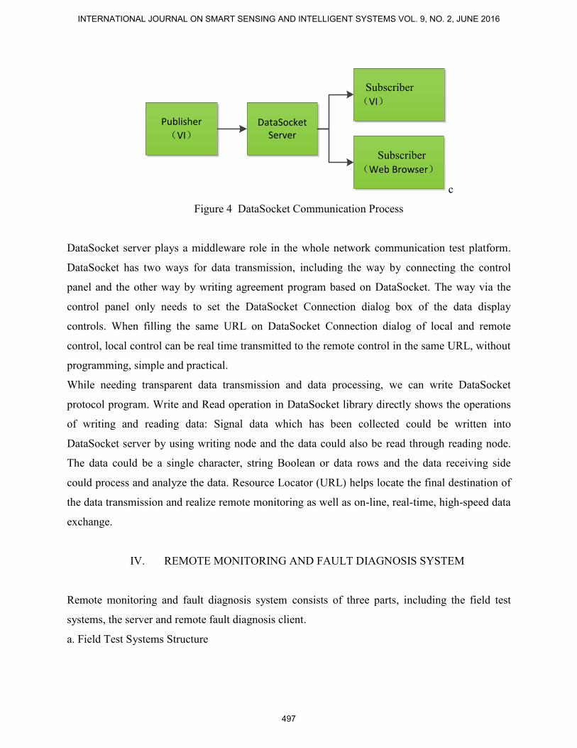
c. DataSocket Working Principle
DataSocket realizes Network communication by using DataSocket library. DataSocket publish
data by three elements called Publisher, DataSocket Server and Subscriber. When publishing
data, the publisher use DataSocket API Interface to transmit data into DataSocket Server. When
receiving data, the subscriber utilizes the API interface to read data from DataSocket Server.
Communication process is shown in Figure 5.
Wu Tao, Liu Zhihua and Liang Miaoyuan, DATASOCKET TECHNOLOGY AND ITS APPLICATION IN EQUIPMENT REMOTE CONDITION MONITORING AND FAULT DIAGNOSIS
496
Publisher
(VI)DataSocket
Server
Subscriber
(VI)
Subscriber
(Web Browser)
c
Figure 4 DataSocket Communication Process
DataSocket server plays a middleware role in the whole network communication test platform.
DataSocket has two ways for data transmission, including the way by connecting the control
panel and the other way by writing agreement program based on DataSocket. The way via the
control panel only needs to set the DataSocket Connection dialog box of the data display
controls. When filling the same URL on DataSocket Connection dialog of local and remote
control, local control can be real time transmitted to the remote control in the same URL, without
programming, simple and practical.
While needing transparent data transmission and data processing, we can write DataSocket
protocol program. Write and Read operation in DataSocket library directly shows the operations
of writing and reading data: Signal data which has been collected could be written into
DataSocket server by using writing node and the data could also be read through reading node.
The data could be a single character, string Boolean or data rows and the data receiving side
could process and analyze the data. Resource Locator (URL) helps locate the final destination of
the data transmission and realize remote monitoring as well as on-line, real-time, high-speed data
exchange.
IV. REMOTE MONITORING AND FAULT DIAGNOSIS SYSTEM
Remote monitoring and fault diagnosis system consists of three parts, including the field test
systems, the server and remote fault diagnosis client.
a. Field Test Systems Structure
INTERNATIONAL JOURNAL ON SMART SENSING AND INTELLIGENT SYSTEMS VOL. 9, NO. 2, JUNE 2016
497

The field test part locates in the front of the whole system, directly drives these devices working.
This part consists of field instruments, control equipment and hardware interface components,
mainly responsible for the implementation of on-site data collection and control functions. Field
Intelligent sensors pick up the original information and provide information, which would be
processed by the signal processing circuits, to the data acquisition card. The computer would
select PXI, USB, GPIB and other bus modes to connect external data acquisition devices with
instruments function hardware in order to realize data acquisition and instrument control. The
structure of the field test part has been shown in Figure 5.
Test Object
Test Excitation
Signal
IntelligentSensor
Signal Conditioning
Circuit
DataAcquisiton
Card
Control Card
Figure 5 System Structure
b. The Server Structure
The server locates in the heart of the entire platform and generally uses high-performance IPC.
As link port between filed and remote troubleshooting communications, on the one hand it
provides a specific operating environment for virtual instrument software and completes on-site
data acquisition, instrument control and management. On the other hand it provides data and
network services to the remote fault diagnosis center, and receives control commands to complete
the control operation to on-site equipments. Through the instrument hardware interface installed
on the IPC, the virtual instrument software based on LabVIEW can control the data acquisition
card to collect the original signal. It also could use LabVIEW's DAQ technology to enables field
devices to input and output analog quantity, realize digital I / O and timing count function. At the
same time, DataSocket technology could help server-side control device collect data and transfer
raw data to remote diagnostics clients.
The server includes a network communication module, data acquisition card module, the
controller module and instrument management module which has been shown in Figure 6.
Wu Tao, Liu Zhihua and Liang Miaoyuan, DATASOCKET TECHNOLOGY AND ITS APPLICATION IN EQUIPMENT REMOTE CONDITION MONITORING AND FAULT DIAGNOSIS
498

Network
Communication
Module
data acquisition
card module
controller module
instrument
management
module
DataSocketCommunication
Figure 6 The Server Structure
The server would communicate with the client through network communication module and
provide serve to the client, including helping to translate the information from customers to
programming languish which could control instrument operation, the acquisition card, the
controller as well as send the data from the acquisition card to the client display.
Data acquisition card module controls the card to acquire electrical signal which has been
adjusted and send these signals to the client. The client could analyze and processing the signals
for fault diagnosis.
The controller module could accept control commands sent by the client as well as program
control instructions provided by the instrument controllers.
The instrument management module could ensure reliable employment of shared resources. It
could help to test and monitor the equipment status and provide alarm to the failures and errors.
c. Remote Fault Diagnosis Client
Remote fault diagnosis client provides human-computer window for monitoring and diagnosis.
The client uses DataSocket technique to read field data, and utilizes LabVIEW signal analysis
module to complete signal processing. The ultimate goal of signal processing is to clearly exhibit
a characteristic signal curve and extract feature information. Combined with years of expert
diagnosis experience, it could help complete fault diagnosis.
Remote fault diagnosis client includes input and output module, human-computer interaction
module, data analysis and processing module and network communication module etc. The
simple structure could be shown in Figure 7.
INTERNATIONAL JOURNAL ON SMART SENSING AND INTELLIGENT SYSTEMS VOL. 9, NO. 2, JUNE 2016
499
data analysis and
processing modul
human-computer
interaction module, Network
Communication
Module
DataSocketCommunication
Figure 7 the Client Structure
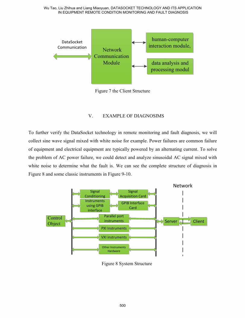
V. EXAMPLE OF DIAGNOSIMS
To further verify the DataSocket technology in remote monitoring and fault diagnosis, we will
collect sine wave signal mixed with white noise for example. Power failures are common failure
of equipment and electrical equipment are typically powered by an alternating current. To solve
the problem of AC power failure, we could detect and analyze sinusoidal AC signal mixed with
white noise to determine what the fault is. We can see the complete structure of diagnosis in
Figure 8 and some classic instruments in Figure 9-10.
Control
Object
Signal Conditioning
Signal Acquisition Card
Instruments using GPIB interface
GPIB Interface Card
Parallel port instruments
PXI Instruments
Other Instruments Hardware
Server Client
VXI instruments
Network
Figure 8 System Structure
Wu Tao, Liu Zhihua and Liang Miaoyuan, DATASOCKET TECHNOLOGY AND ITS APPLICATION IN EQUIPMENT REMOTE CONDITION MONITORING AND FAULT DIAGNOSIS
500

Figure 9 ATE Main Cabinet
Figure 10 Control device and its cards
a. Synchronous and high-speed data sampling with DAQ
Remote test system has high requirements for signal acquisition and the data acquisition
technique based on the software called LabVIEW could be provided with the advantages which
others do not possess. We could write powerful signal acquisition program by using DAQ
module in LabVIEW and with that we users could not only meet on the basic need of high-speed
acquisition but also could design a convenient and friendly acquisition program according to our
INTERNATIONAL JOURNAL ON SMART SENSING AND INTELLIGENT SYSTEMS VOL. 9, NO. 2, JUNE 2016
501

own favor. The experiment in this paper relies on current laboratory equipment and has selected
the PXI-5114 digitizer type in NI Company. This card shows powerful features. It could achieve
real-time sampling at the rate of 250MS/s and equivalent-time sampling at the rate of 5GB/s
respectively. PXI-5114 also has the ability of dual-channel synchronous sampling with its input
value ranging from 40mV to 40V and the 125MHz bandwidth. When using the card to acquire
the waveform data, we could make use of 256 MB onboard memory on each channel to store
those great amounts of waveform data. In addition, PXI-5114 also has a series of trigger
functions including SDTV / HDTV. This card could connect to the computer through PXI bus
and we users could be convenient to program by using more than 50 built-in measurement and
analysis functions. Detailed specifications would be shown in the table1.
Table 1: Performance parameters on PXI-5114
Bus Type PXI
Operating System Real-Time Systems、Linux、Windows
LabVIEW RT Support YES
Trigger mode Digital, analog, video
External Clock YES
I / O connector BNC connectors, SMB male side
Sampling Rate 250MS/s
bandwidth 125MHz
Minimum voltage range -20mV, 20mV
Frequency Range 0~125MHz
The maximum analog input voltage -20V, 20V
Board storage 256MB/Channel
Number of Channels 2
After installing DAQ-mx software in the internet, we could open the software and detect this card.
We could carry out a series of execution like viewing the card pin information, configuring
virtual channels, setting the measurement mode before performing system testing and diagnostic.
b. Example
Wu Tao, Liu Zhihua and Liang Miaoyuan, DATASOCKET TECHNOLOGY AND ITS APPLICATION IN EQUIPMENT REMOTE CONDITION MONITORING AND FAULT DIAGNOSIS
502

Sine wave can be detected in power extension module or generated directly by the signal
generator. We generated directly is the sine-wave signal mixed uniformly white noise by the
virtual instrument signal generator module. The sine signal has the amplitude of 5V and the
frequency of 10HZ. The signal data was collected through Virtual Instrument DAQ board and
would be stored in a computer database. The number of device is 1, the channel is 0, the sampling
rate is 1000 and the sampling buffer was set 5000. The sampling program was written in
LabVIEW and the front panel and block diagram are shown in Figure 11-12.
Figure 11 Sample of Front Panel
Figure 12 Sample of Block Diagram
The server side wrote virtual instrument program in LabVIEW. Through built-in DAQ board
driver, it could control device to capture the signal measured and save to the database within a
computer. When entering the server’s computer address on the URL panel, we could write data
through DateSocket Writer node. The server’s default address is its local host. Figure 11 has
INTERNATIONAL JOURNAL ON SMART SENSING AND INTELLIGENT SYSTEMS VOL. 9, NO. 2, JUNE 2016
503

shown sinusoidal signal mixed with the white noise. The signal was written and displayed on the
oscilloscope instrument.
The treatment of sampling and analyzing measured signal would provide data basis to determine
the place where the fault happened. It is an important means of dealing with the sampled data to
send sample data to the remote diagnostics clients. We could realize the telecommunications by
writing DataSocket communications-server program. Users could design friendly transmission
interface as their own favor and enter the URL address of the local server on the display panel. In
addition, users can enter ‘ipconfig’ via ‘cmd’ window to view the local IP address or directly
default as ‘localhost’ which would reach the same effort. DataSocket server-side program would
write the data which needs to transmit by DateSocket Writer node. Here we also realize
transmission sinusoidal signal mixed with white noise and could view the signal transmitted in
the local scope meter. The consequence has been shown in Figure 13-14.
Figure 13 Front Panel of Server fault signal
Figure 14 Block Diagram of Server fault signal
Wu Tao, Liu Zhihua and Liang Miaoyuan, DATASOCKET TECHNOLOGY AND ITS APPLICATION IN EQUIPMENT REMOTE CONDITION MONITORING AND FAULT DIAGNOSIS
504

The client read out data from the URL specified location by DateSocket Reader node and
displayed on the client oscilloscope as shown in Figure 15.
Figure 15 Client reception monitoring signal
In order to analyze the data which has been received, we have used signal analysis sub-module
provided by LabVIEW to make spectral analysis. Therefore, the characteristic frequency of
sinusoidal signal would be obtained. Then through a filter (using anti-Schiff filter) we would
filter white noise and get frequency and amplitude by time domain analysis. Based on analysis
operations to the received signal, we could compare the fault characteristic curve database which
has been established to monitor device status and realize fault diagnosis. The result has been
shown in Figure 16-17.
Figure 16 Fault signal spectrum analysis
INTERNATIONAL JOURNAL ON SMART SENSING AND INTELLIGENT SYSTEMS VOL. 9, NO. 2, JUNE 2016
505

Figure 17 Fault signal filtering
VI. CONCLUTION
In summary, the virtual instrument technology based on networks makes full use of its own
advantages in software and hardware. For the reality of monitoring equipment condition and fault
diagnosis in grass-roots units, this technique has provided one cost-effective mean of supporting
equipment. By using DataSocket to help network transmission, we have overcome inefficiencies
in the underlying network programming, poor real-time data transmission and other
shortcomings. DataSocket technique has truly helped make network programming simple and
quick and make test data transmit in real-time. From the instance to transmit sine wave signal
mixed with white noise, we can see that experts will not need to visit the site and can monitor
equipment status at the remote site in real time. Besides, experts and can analyze and process
fault signals to achieve the purpose of fault diagnosis.
REFERENCES
[1] LiFengbao, LiLing, WangXiaodong. Networked Measurement and Control System Based on
Virtual Instrument [J]. Scientific Instrument, 2004, 25(4): 295-297
[2] ChenGuoshun, Yuhanwei. Test Engineering and LabVIEW Applications [J]. 2013.
[3] MoHuifang, Raominghui. Motor Audio Remote Fault Diagnosis System Based on
DataSocket Technology [J]. Automation and Instrumentation, 2013 (3): 175-176.
Wu Tao, Liu Zhihua and Liang Miaoyuan, DATASOCKET TECHNOLOGY AND ITS APPLICATION IN EQUIPMENT REMOTE CONDITION MONITORING AND FAULT DIAGNOSIS
506

[4]DataSocket Transfer Protocol Overview.Http://www.ni.com.
[5] JiangWei, ZhangXiaobo, LaiQinggui. Instrument Communication Technology Based on
LabVIEW [J]. Computer Measurement & Control, 2013, 21(4): 1030-1032.
[6] WangJiping, ZhaoZhe, TianKechun. Communication Measurement Technology Based on
LabVIEW [J]. Automation and Instrumentation, 2011, 26(1): 29-31.
[7]Yan He and Benxian Xiao, “Research of The Forklift Power-Assisted Steering System Based
on Safety Steering Speed Control” International Journal On Smart Sensing and Intelligent
Systems. vol. 8, no. 1, March 2015 .
[8]. J. H. Liu, Y. F. Chen, T. S. Lin, C. P. Chen, P. T. Chen, T.H. Wen, C. H. Sun, J. Y.
Juang2, and J. A. Jiang, “ An air Quality Monitoring System for Urban Areas based on the
Technology of Wireless Sensor Networks,” International Journal on Smart Sensing and
Intelligent Systems, vol. 5, no. 1, march 2012 page 192-217.
[9]. N. Samanta, A. K. Chanda, C. RoyChaudhuri , “An Energy Efficient, Minimally Intrusive
Multi-Sensor Intelligent System for Health Monitoring of Elderly People,” International Journal
on Smart Sensing and Intelligent Systems vol. 7, no. 2, June 2014, page no 762-780.
[10]. J. Yang, W. Chen, Z. Fu, W. Wu, and Z. Xie,” Research of Multi Sensor Intelligent System
Signal Fusion and Reconstruction,” International Journal on Smart Sensing and Intelligent
Systems, vol. 7, no. 4, December 2014 page 1701-1716.
[11]WangLin,ZhengZhengqi, Design of radar ranging data transmission system based on
DataSocket[J], Electronic Measurement Technology, 2011.34(1):99-101
[12]Bai JinPeng, The speed research of transferring images through DataSocket[J], Electronic
Measurement Technology, 2015.38(12):49-53
[13] Chen Zheng, WangYing, Asynchronous motor test system based on LabVIEW and OPC[J],
Industrial Communication,2015.10:68-71
[14] ZhangFeng, WangYu, Remote data acquisition system based on C/S Mode in the LabVIEW
environment, Industrial & Science Tribune,2014(7)
[15] XuJie, Chencheng,ZhaoGuowei. Design of Remote Data Acquisition System Based on
LabVIEW[J], Microcomputer Information 2007(28):62-63.
[16] XU Fuxin , LUO Ming, CHEN Fang, HE Jishan, Design and Implementation of Video
Acquisition in a Remote Measurement and Control System Based on LabVIEW[J], Computer
Engineering & Science, 2009, 31(5):24-26.
INTERNATIONAL JOURNAL ON SMART SENSING AND INTELLIGENT SYSTEMS VOL. 9, NO. 2, JUNE 2016
507

[17] Yao Juan,Zhang Zhijie,Li Lifang, Data Acquisition System Design and Implementation
based on LabVIEW and TCP[J], Application of Electronic Technique, 2012(7):72-74.
[18] ZHANG Zhi-jun,XU Xiao-li,WU Guo-xin, Wireless data technology Acquisition System
based on LabVIEW and Wi-Fi [J]. Control and Instruments in Chemical Industry, 2013,
40(3):367-371.
[19] LI Ning, YUE Weiwei, Implement remote control technology based on LabVIEW [J],
Equipment Manufacturing Technology, 2014(11):250-251.
[20] Jiang Chaoyang, Zhu Chen. Virtual Instrument applies in Equipment Remote Monitoring
and Fault Diagnosis Based on DataSocket Technology [J]. Digital Technology &
Application, 2012(5):63-64.
Wu Tao, Liu Zhihua and Liang Miaoyuan, DATASOCKET TECHNOLOGY AND ITS APPLICATION IN EQUIPMENT REMOTE CONDITION MONITORING AND FAULT DIAGNOSIS
508