datasheet - laird techcdn.lairdtech.com/home/brandworld/files/datasheet (hig...3.4 18 aug 2014...
TRANSCRIPT

A
Datasheet BTM44x Version 3.6
BTM44x Datasheet
Embedded Wireless Solutions Support Center:
http://ews-support.lairdtech.com
www.lairdtech.com/wireless
2
© Copyright 2015 Laird. All Rights Reserved
Americas: +1-800-492-2320 Europe: +44-1628-858-940
Hong Kong: +852 2923 0610
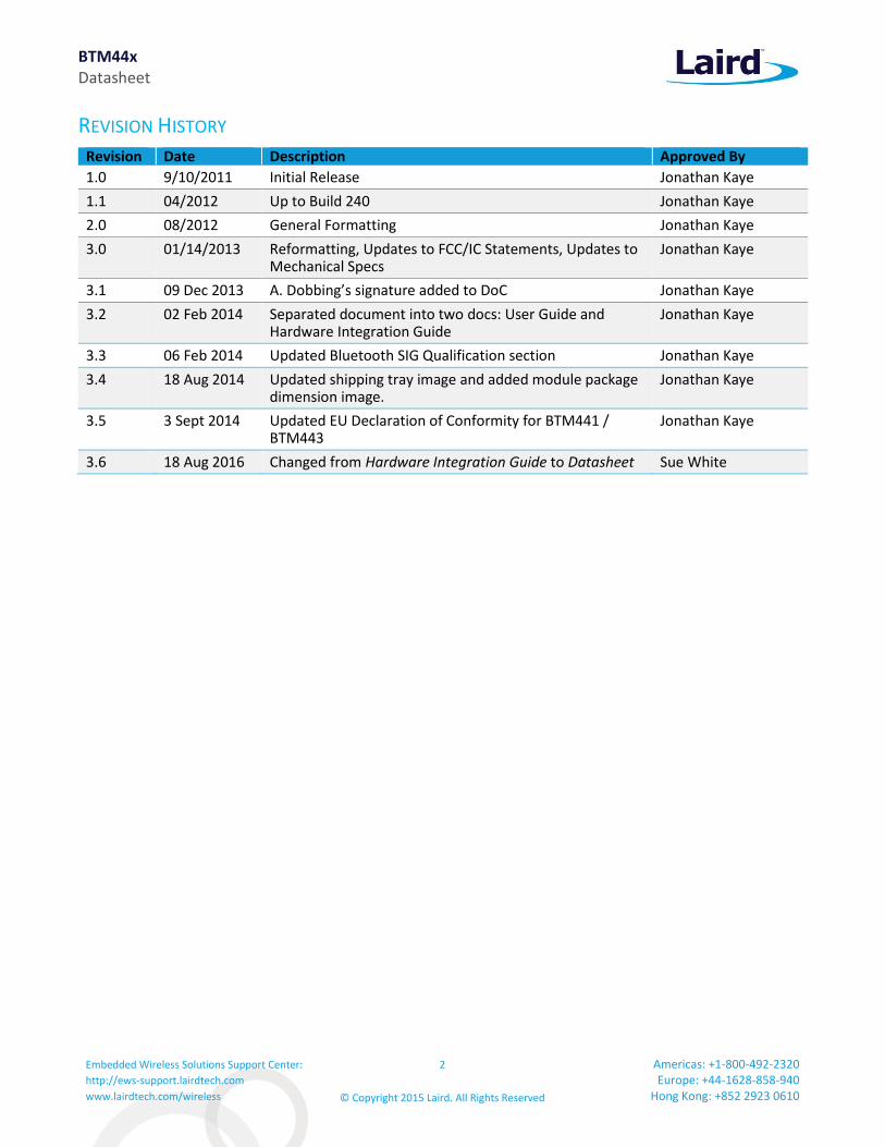
REVISION HISTORY Revision Date Description Approved By
1.0 9/10/2011 Initial Release Jonathan Kaye
1.1 04/2012 Up to Build 240 Jonathan Kaye
2.0 08/2012 General Formatting Jonathan Kaye
3.0 01/14/2013 Reformatting, Updates to FCC/IC Statements, Updates to Mechanical Specs
Jonathan Kaye
3.1 09 Dec 2013 A. Dobbing’s signature added to DoC Jonathan Kaye
3.2 02 Feb 2014 Separated document into two docs: User Guide and Hardware Integration Guide
Jonathan Kaye
3.3 06 Feb 2014 Updated Bluetooth SIG Qualification section Jonathan Kaye
3.4 18 Aug 2014 Updated shipping tray image and added module package dimension image.
Jonathan Kaye
3.5 3 Sept 2014 Updated EU Declaration of Conformity for BTM441 / BTM443
Jonathan Kaye
3.6 18 Aug 2016 Changed from Hardware Integration Guide to Datasheet Sue White
BTM44x Datasheet
Embedded Wireless Solutions Support Center:
http://ews-support.lairdtech.com
www.lairdtech.com/wireless
3
© Copyright 2015 Laird. All Rights Reserved
Americas: +1-800-492-2320 Europe: +44-1628-858-940
Hong Kong: +852 2923 0610
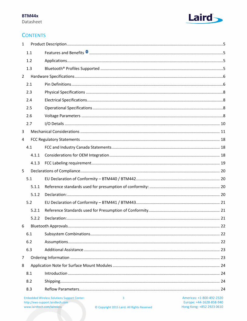
CONTENTS
1 Product Description ............................................................................................................................................5
1.1 Features and Benefits ........................................................................................................................5
1.2 Applications............................................................................................................................................5
1.3 Bluetooth® Profiles Supported ..............................................................................................................5
2 Hardware Specifications .....................................................................................................................................6
2.1 Pin Definitions ........................................................................................................................................6
2.3 Physical Specifications ...........................................................................................................................8
2.4 Electrical Specifications ..........................................................................................................................8
2.5 Operational Specifications .....................................................................................................................8
2.6 Voltage Parameters ...............................................................................................................................8
2.7 I/O Details ........................................................................................................................................... 10
3 Mechanical Considerations ............................................................................................................................. 11
4 FCC Regulatory Statements ............................................................................................................................. 18
4.1 FCC and Industry Canada Statements ................................................................................................. 18
4.1.1 Considerations for OEM Integration ................................................................................................... 18
4.1.3 FCC Labeling requirement ................................................................................................................... 19
5 Declarations of Compliance ............................................................................................................................. 20
5.1 EU Declaration of Conformity – BTM440 / BTM442 ........................................................................... 20
5.1.1 Reference standards used for presumption of conformity: ............................................................... 20
5.1.2 Declaration: ......................................................................................................................................... 20
5.2 EU Declaration of Conformity – BTM441 / BTM443 ........................................................................... 21
5.2.1 Reference Standards used for Presumption of Conformity................................................................ 21
5.2.2 Declaration: ......................................................................................................................................... 21
6 Bluetooth Approvals ........................................................................................................................................ 22
6.1 Subsystem Combinations .................................................................................................................... 22
6.2 Assumptions ........................................................................................................................................ 22
6.3 Additional Assistance .......................................................................................................................... 23
7 Ordering Information ...................................................................................................................................... 23
8 Application Note for Surface Mount Modules ................................................................................................ 24
8.1 Introduction ........................................................................................................................................ 24
8.2 Shipping............................................................................................................................................... 24
8.3 Reflow Parameters .............................................................................................................................. 24

BTM44x Datasheet
Embedded Wireless Solutions Support Center:
http://ews-support.lairdtech.com
www.lairdtech.com/wireless
4
© Copyright 2015 Laird. All Rights Reserved
Americas: +1-800-492-2320 Europe: +44-1628-858-940
Hong Kong: +852 2923 0610
9 References ....................................................................................................................................................... 26
10 Glossary of Terms................................................................................................................................ 27
11 Related Documents and Files .............................................................................................................. 28

BTM44x Datasheet
Embedded Wireless Solutions Support Center:
http://ews-support.lairdtech.com
www.lairdtech.com/wireless
5
© Copyright 2015 Laird. All Rights Reserved
Americas: +1-800-492-2320 Europe: +44-1628-858-940
Hong Kong: +852 2923 0610
1 PRODUCT DESCRIPTION
The BTM44x Bluetooth® modules from Laird Technologies have been designed to meet the needs of developers who wish to add robust, short range Bluetooth data connectivity to their products. They are based on the market leading Cambridge Silicon Radio BC04 chipset, providing exceptionally low power consumption with outstanding range. They support the latest Bluetooth® Version 2.1 Specification, providing the important advantage of Secure Simple Pairing, which improves security and enhances the ease of use for end customers.
With physical sizes as small as 12.5 x 18.0mm and best of class, low-power operation, these modules are the ideal choice for applications where designers need both performance and minimum size. For maximum flexibility in systems integration, the modules are designed to support a separate power supply for I/O.
To aid product development and integration, Laird Technologies has integrated a complete Bluetooth protocol stack within the modules, including support for multiple Bluetooth Profiles. The modules are fully qualified as Bluetooth End Products, allowing designers to integrate them within their own products with no further Bluetooth Qualification. They can then list and promote their products on the Bluetooth website free of charge.
Support for Serial Port Profile (SPP), Human Interface Device (HID) profile and Health Device Profile (HDP) are included in the module. The support of the Bluetooth Sig’s Health Device Profile makes this the ideal module for development of Continua compliant medical and wellness devices. By default the Health Device Profile supports the ISO/IEEE 11073-10415 device specialization for weigh scales, but additional specializations for glucose and thermometer are available with more upon request.
Communication is available to the module over a serial UART utilizing either a custom Multi-point Packet Protocol API or comprehensive AT commands. Combined with a low cost developer’s kit, this ensures that the choice of Laird Technologies modules guarantees the fastest route to market.
Features and Benefits
Bluetooth® v2.1+EDR Adaptive Frequency Hopping to cope
with interference from other wireless devices
Secure Simple Pairing support External or internal antenna options Comprehensive AT interface for
simple programming Alternate Packet based interface for
complex programming Bluetooth® END Product Qualified Compact size Class 2 output – 4dBm Low power operation UART interface
Applications
Embedded Devices
Phone Devices
Phone Accessories
Security Devices
Medical and Wellness Devices
Automotive Applications
Bluetooth® Profiles Supported
Serial Port Profile (SPP) Human Interface Device (HID) Profile Host
and device supported Health Device Profile (HDP): Agent supported IEEE Device Specialization 11073-10415 (Weight Scale) IEEE Device Specialization 11073 - 10408 (Thermometer) IEEE Device Specialization 11073 – 10417 (Glucose)

BTM44x Datasheet
Embedded Wireless Solutions Support Center:
http://ews-support.lairdtech.com
www.lairdtech.com/wireless
6
© Copyright 2015 Laird. All Rights Reserved
Americas: +1-800-492-2320 Europe: +44-1628-858-940
Hong Kong: +852 2923 0610
2 HARDWARE SPECIFICATIONS Pin Definitions
Table 1: Pin definitions
Signal Description Voltage Specification
1 Unused
2 GND
3 UART_CTS Clear to Send I/P VUSB
4 UART_RXD Receive data I/P VUSB
5 UART_RTS Request to Send O/P VUSB
6 UART_TXD Transmit data O/P VUSB
7 GND
8 SPI_CSB SPI bus chip select I/P VIO
9 SPI_MISO SPI bus serial O/P VIO
10 SPI_MOSI SPI bus serial I/P VIO
11 SPI_CLK SPI bus clock I/P VIO
12 VDD_USB USB & UART supply voltage
13 VDD_IO I/O supply voltage
14 VDD_IN Main supply voltage
15 GND
16 PCM_IN PCM Data I/P VIO
17 PCM_SYNC PCM sync I/P VIO
18 PCM_CLK PCM clock I/P VIO
19 PCM_OUT PCM Data O/P VIO
20 RESET Module reset I/P See note 2
21 GPIO4 I/O for host- BT_Active BT_State VIO
22 GPIO2 / UART_DCD I/O for host VIO
23 GND
24 Unused
25 Unused See note 3
26 Unused See note 3
27 Unused See note 3
28 GND See note 3
29 ANT (BTM440 / 442 only) Antenna connection (50 ohm matched)
See note 3
30 GND See note 3
31 Unused See note 3
32 Unused See note 3
33 Unused See note 3
34 Unused See note 3
BTM44x Datasheet
Embedded Wireless Solutions Support Center:
http://ews-support.lairdtech.com
www.lairdtech.com/wireless
7
© Copyright 2015 Laird. All Rights Reserved
Americas: +1-800-492-2320 Europe: +44-1628-858-940
Hong Kong: +852 2923 0610
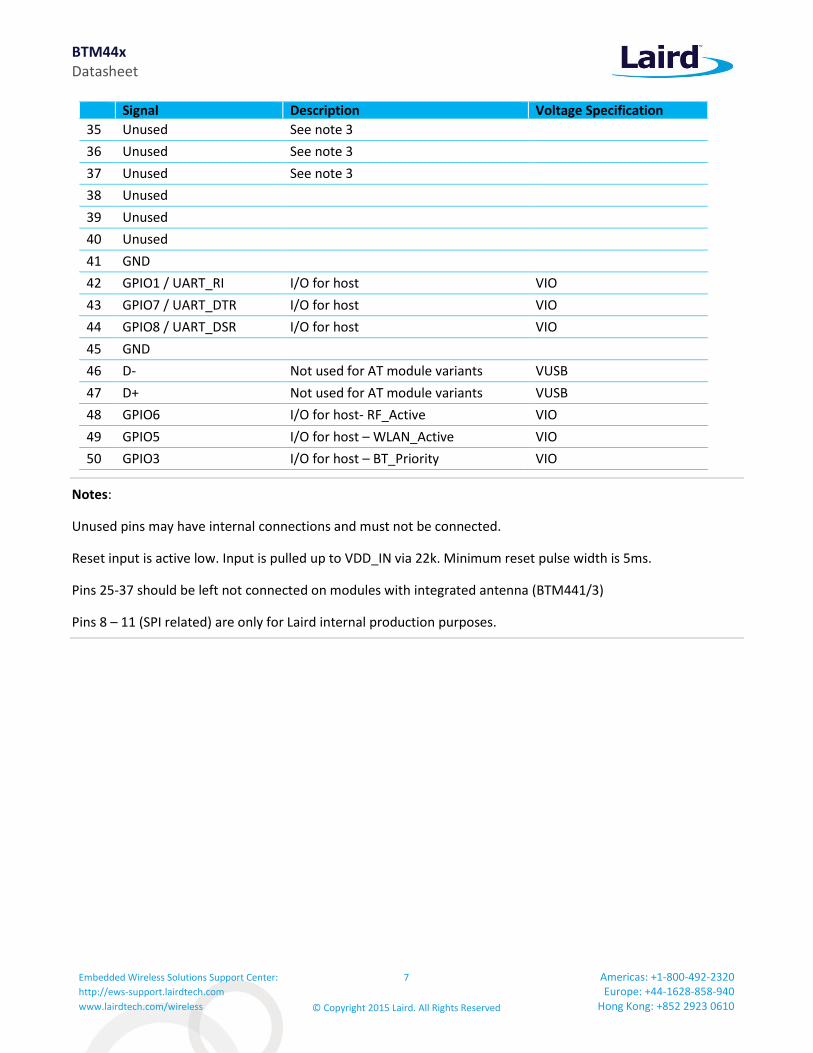
Signal Description Voltage Specification
35 Unused See note 3
36 Unused See note 3
37 Unused See note 3
38 Unused
39 Unused
40 Unused
41 GND
42 GPIO1 / UART_RI I/O for host VIO
43 GPIO7 / UART_DTR I/O for host VIO
44 GPIO8 / UART_DSR I/O for host VIO
45 GND
46 D- Not used for AT module variants VUSB
47 D+ Not used for AT module variants VUSB
48 GPIO6 I/O for host- RF_Active VIO
49 GPIO5 I/O for host – WLAN_Active VIO
50 GPIO3 I/O for host – BT_Priority VIO
Notes:
Unused pins may have internal connections and must not be connected.
Reset input is active low. Input is pulled up to VDD_IN via 22k. Minimum reset pulse width is 5ms.
Pins 25-37 should be left not connected on modules with integrated antenna (BTM441/3)
Pins 8 – 11 (SPI related) are only for Laird internal production purposes.
BTM44x Datasheet
Embedded Wireless Solutions Support Center:
http://ews-support.lairdtech.com
www.lairdtech.com/wireless
8
© Copyright 2015 Laird. All Rights Reserved
Americas: +1-800-492-2320 Europe: +44-1628-858-940
Hong Kong: +852 2923 0610
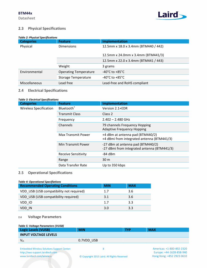
Physical Specifications
Table 2: Physical Specifications
Categories Feature Implementation
Physical Dimensions 12.5mm x 18.0 x 3.4mm (BTM440 / 442)
12.5mm x 24.0mm x 3.4mm (BTM441/3)
12.5mm x 22.0 x 3.4mm (BTM441 / 443)
Weight 3 grams
Environmental Operating Temperature -40°C to +85°C
Storage Temperature -40°C to +85°C
Miscellaneous Lead free Lead-free and RoHS compliant
Electrical Specifications
Table 3: Electrical Specifications
Categories Feature Implementation
Wireless Specification Bluetooth® Version 2.1+EDR
Transmit Class Class 2
Frequency 2.402 – 2.480 GHz
Channels 79 channels Frequency Hopping Adaptive Frequency Hopping
Max Transmit Power +4 dBm at antenna pad (BTM440/2) +4 dBmi from integrated antenna (BTM441/3)
Min Transmit Power -27 dBm at antenna pad (BTM440/2) -27 dBmi from integrated antenna (BTM441/3)
Receive Sensitivity -84 dBm
Range 30 m
Data Transfer Rate Up to 350 kbps
Operational Specifications
Table 4: Operational Specifiations
Recommended Operating Conditions MIN MAX
VDD_USB (USB compatibility not required) 1.7 3.6
VDD_USB (USB compatibility required) 3.1 3.6
VDD_IO 1.7 3.3
VDD_IN 3.0 3.3
Voltage Parameters
Table 5: Voltage Parameters (VUSB)
Logic Levels (VUSB) MIN TYP MAX
INPUT VOLTAGE LEVELS
Vih 0.7VDD_USB

BTM44x Datasheet
Embedded Wireless Solutions Support Center:
http://ews-support.lairdtech.com
www.lairdtech.com/wireless
9
© Copyright 2015 Laird. All Rights Reserved
Americas: +1-800-492-2320 Europe: +44-1628-858-940
Hong Kong: +852 2923 0610
Logic Levels (VUSB) MIN TYP MAX
Vil 2.7<VDD_USB<3.0 -0.4 +0.8
1.7<VDD_USB<1.9 -0.4 +0.4
OUTPUT VOLTAGE LEVELS (1.7<VDD_USB<1.9)
Voh (Iout = -4mA) VDD_USB – 0.4
Vol (Iout = 4mA) 0.4
OUTPUT VOLTAGE LEVELS (2.7<VDD_USB<3.0)
Voh (Iout = -4mA) VDD_USB – 0.2
Vol (Iout = 4mA) 0.2
Note: VDD_USB must be connected to power the USB and UART interfaces.
Table 6: Voltage Parameters (VIO)
Logic Levels (VIO) MIN TYP MAX
INPUT VOLTAGE LEVELS
Vih 0.7VDD_IO
Vil 2.7<VDD_IO<3.0 -0.4 +0.8
1.7<VDD_IO<1.9 -0.4 +0.4
OUTPUT VOLTAGE LEVELS (1.7 < VDD_IO < 1.9)
Voh (Iout = -4mA) VDD_IO – 0.4
Vol (Iout = 4mA) 0.4
OUTPUT VOLTAGE LEVELS (2.7 < VDD_IO < 3.0)
Voh (Iout = -4mA) VDD_IO – 0.2
Vol (Iout = 4mA) 0.2
BTM44x Datasheet
Embedded Wireless Solutions Support Center:
http://ews-support.lairdtech.com
www.lairdtech.com/wireless
10
© Copyright 2015 Laird. All Rights Reserved
Americas: +1-800-492-2320 Europe: +44-1628-858-940
Hong Kong: +852 2923 0610
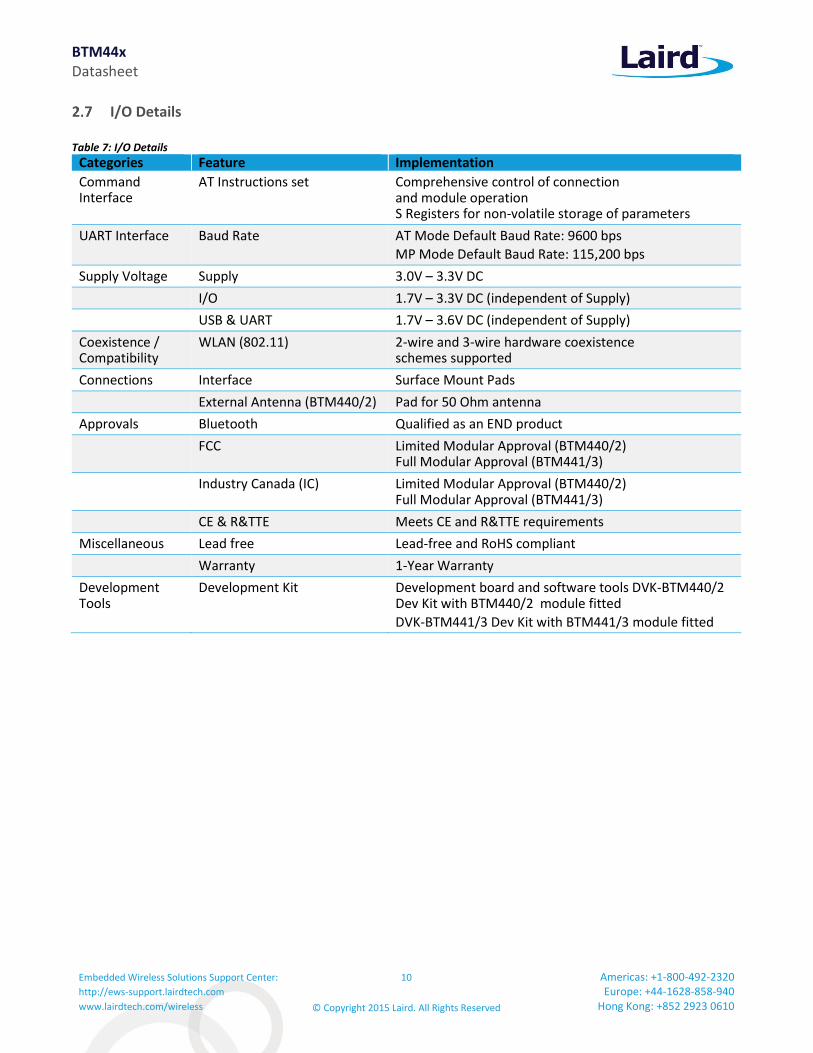
I/O Details
Table 7: I/O Details
Categories Feature Implementation
Command Interface
AT Instructions set Comprehensive control of connection and module operation S Registers for non-volatile storage of parameters
UART Interface Baud Rate AT Mode Default Baud Rate: 9600 bps
MP Mode Default Baud Rate: 115,200 bps
Supply Voltage Supply 3.0V – 3.3V DC
I/O 1.7V – 3.3V DC (independent of Supply)
USB & UART 1.7V – 3.6V DC (independent of Supply)
Coexistence / Compatibility
WLAN (802.11) 2-wire and 3-wire hardware coexistence schemes supported
Connections Interface Surface Mount Pads
External Antenna (BTM440/2) Pad for 50 Ohm antenna
Approvals Bluetooth Qualified as an END product
FCC Limited Modular Approval (BTM440/2) Full Modular Approval (BTM441/3)
Industry Canada (IC) Limited Modular Approval (BTM440/2) Full Modular Approval (BTM441/3)
CE & R&TTE Meets CE and R&TTE requirements
Miscellaneous Lead free Lead-free and RoHS compliant
Warranty 1-Year Warranty
Development Tools
Development Kit Development board and software tools DVK-BTM440/2 Dev Kit with BTM440/2 module fitted
DVK-BTM441/3 Dev Kit with BTM441/3 module fitted
BTM44x Datasheet
Embedded Wireless Solutions Support Center:
http://ews-support.lairdtech.com
www.lairdtech.com/wireless
11
© Copyright 2015 Laird. All Rights Reserved
Americas: +1-800-492-2320 Europe: +44-1628-858-940
Hong Kong: +852 2923 0610
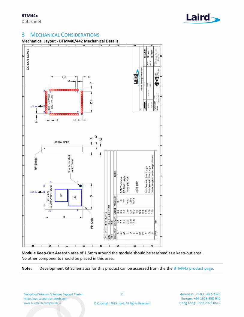
3 MECHANICAL CONSIDERATIONS Mechanical Layout - BTM440/442 Mechanical Details
Module Keep-Out Area:An area of 1.5mm around the module should be reserved as a keep-out area. No other components should be placed in this area.
Note: Development Kit Schematics for this product can be accessed from the the BTM44x product page.

BTM44x Datasheet
Embedded Wireless Solutions Support Center:
http://ews-support.lairdtech.com
www.lairdtech.com/wireless
12
© Copyright 2015 Laird. All Rights Reserved
Americas: +1-800-492-2320 Europe: +44-1628-858-940
Hong Kong: +852 2923 0610
Mechanical layout - BTM440/442 Mechanical Details
Module Keep-Out Area:An area of 1.5mm around the module should be reserved as a keep-out area. No other components should be placed in this area.
Note: Development Kit Schematics for this product can be accessed from the the BTM44x product page.

BTM44x Datasheet
Embedded Wireless Solutions Support Center:
http://ews-support.lairdtech.com
www.lairdtech.com/wireless
13
© Copyright 2015 Laird. All Rights Reserved
Americas: +1-800-492-2320 Europe: +44-1628-858-940
Hong Kong: +852 2923 0610
Mechanical layout - BTM440/442 Mechanical Details
WARNING: Test point dimensions are for reference only. DO NOT make electrical connections to these test points, this will void the warranty. Laird does not recommend routing on the top layer underneath the module.

BTM44x Datasheet
Embedded Wireless Solutions Support Center:
http://ews-support.lairdtech.com
www.lairdtech.com/wireless
14
© Copyright 2015 Laird. All Rights Reserved
Americas: +1-800-492-2320 Europe: +44-1628-858-940
Hong Kong: +852 2923 0610
Mechanical layout - BTM441/443 Mechanical Details
Module Keep-Out Area:An area of 1.5mm around the module should be reserved as a keep-out area. No other components should be placed in this area.
Note: Development Kit Schematics for this product can be accessed from the BTM44x product page.

BTM44x Datasheet
Embedded Wireless Solutions Support Center:
http://ews-support.lairdtech.com
www.lairdtech.com/wireless
15
© Copyright 2015 Laird. All Rights Reserved
Americas: +1-800-492-2320 Europe: +44-1628-858-940
Hong Kong: +852 2923 0610
Mechanical layout - BTM441/443 Mechanical Details
Module Keep-Out Area:An area of 1.5mm around the module should be reserved as a keep-out area. No other components should be placed in this area.
Note: Development Kit Schematics for this product can be accessed from the following link: DVK Schematics – BTM44x

BTM44x Datasheet
Embedded Wireless Solutions Support Center:
http://ews-support.lairdtech.com
www.lairdtech.com/wireless
16
© Copyright 2015 Laird. All Rights Reserved
Americas: +1-800-492-2320 Europe: +44-1628-858-940
Hong Kong: +852 2923 0610
Mechanical layout - BTM441/443 Mechanical Details
BTM44x Datasheet
Embedded Wireless Solutions Support Center:
http://ews-support.lairdtech.com
www.lairdtech.com/wireless
17
© Copyright 2015 Laird. All Rights Reserved
Americas: +1-800-492-2320 Europe: +44-1628-858-940
Hong Kong: +852 2923 0610
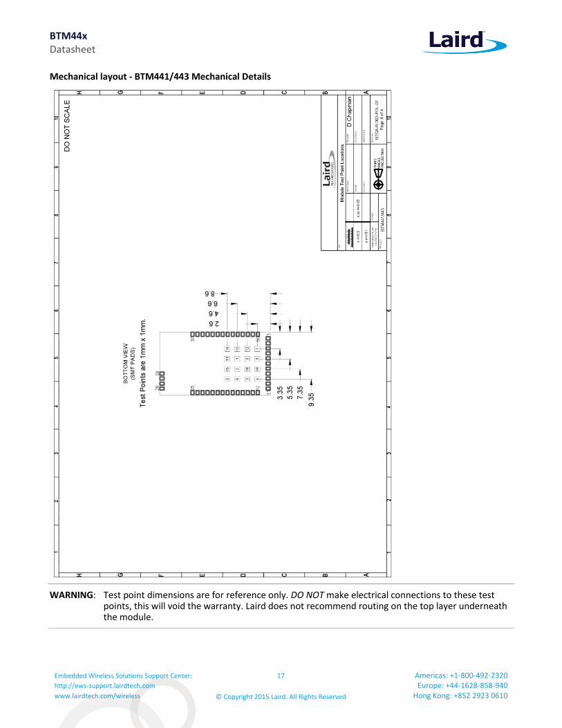
Mechanical layout - BTM441/443 Mechanical Details
WARNING: Test point dimensions are for reference only. DO NOT make electrical connections to these test points, this will void the warranty. Laird does not recommend routing on the top layer underneath the module.

BTM44x Datasheet
Embedded Wireless Solutions Support Center:
http://ews-support.lairdtech.com
www.lairdtech.com/wireless
18
© Copyright 2015 Laird. All Rights Reserved
Americas: +1-800-492-2320 Europe: +44-1628-858-940
Hong Kong: +852 2923 0610
4 FCC REGULATORY STATEMENTS
FCC and Industry Canada Statements
The OEM’s final equipment user manual must show the following statement:
This device complies with part 15 of the FCC Rules. Operation is subject to the following two conditions: (1) This device may not cause harmful interference, and (2) this device must accept any interference received, including interference that may cause undesired operation.
4.1.1 Considerations for OEM Integration
Changes or modifications not expressly approved by Laird Technologies could void the user’s authority to operate the equipment.
Designers should note the distinction that the FCC makes regarding portable and mobile devices. Mobile devices are defined as products that are not used closer than 20cm to the human body, whereas portable devices can be used closer that 20cm to the body. A device may be used in portable exposure conditions with no restrictions on host platforms when the averaged output power is less than the low power threshold for an uncontrolled environment ≤ 60/f(GHz) i.e. 25mW for a 2.4Ghz device. The Maximum Power Exposure for the BTM44x has been evaluated and found to comply with the low power threshold for an uncontrolled environment. Refer to FCC document KDB 447498 for more information on RF exposure procedures and equipment authorization policies for mobile and portable devices.
The BTM44x comply with the FCC RF radiation exposure limits set forth for an uncontrolled environment. This device and its antenna must not be co-located or operating in conjunction with any other antenna or transmitter except in accordance with FCC multi-transmitter product procedures. These procedures could require RF exposure evaluation to be re-evaluated on the complete product.
The installer of this module into host equipment must ensure his equipment complies with the FCC RF Exposure requirements set forth in 47 CFR 2.1091 or 2.1093
The BTM44x comply with the RSS-102RF radiation exposure limits set forth for an uncontrolled environment. If this device and its antenna is co-located or operating in conjunction with any other antenna or transmitter RF exposure evaluation should be re-evaluated on the complete product by a qualified test house.
The installer of this module into host equipment must ensure his equipment complies with the Industry Canada RSS-102 RF Exposure requirements.
BTM440 / BTM442
These modules hold a limited modular approval. Approval with any other antenna configuration or layout other than that approved will necessitate additional radiated emission testing to be performed.
The modules were approved with the following antenna:
RF Solutions: ANT-24G-WHJ-SMA 0dBi

BTM44x Datasheet
Embedded Wireless Solutions Support Center:
http://ews-support.lairdtech.com
www.lairdtech.com/wireless
19
© Copyright 2015 Laird. All Rights Reserved
Americas: +1-800-492-2320 Europe: +44-1628-858-940
Hong Kong: +852 2923 0610
4.1.3 FCC Labeling requirement
4.1.3.1 BTM440 / BTM442
If the FCC ID is not visible when the module is installed inside another device, then the outside of the device into which the module is installed must also display a label referring to the enclosed module. This exterior label can use wording such as the following: “Contains Transmitter Module FCC ID: PI4410B” or “Contains FCC ID: PI4410B”. Any similar wording that expresses the same meaning may be used.
4.1.3.2 BTM441 / BTM443
If the FCC ID is not visible when the module is installed inside another device, then the outside of the device into which the module is installed must also display a label referring to the enclosed module. This exterior label can use wording such as the following: “Contains Transmitter Module FCC ID: PI4411B” or “Contains FCC ID: PI4411B.” Any similar wording that expresses the same meaning may be used.
BTM44x Datasheet
Embedded Wireless Solutions Support Center:
http://ews-support.lairdtech.com
www.lairdtech.com/wireless
20
© Copyright 2015 Laird. All Rights Reserved
Americas: +1-800-492-2320 Europe: +44-1628-858-940
Hong Kong: +852 2923 0610
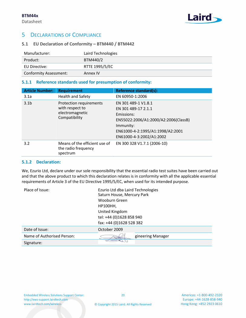
5 DECLARATIONS OF COMPLIANCE
EU Declaration of Conformity – BTM440 / BTM442
Manufacturer: Laird Technologies
Product: BTM440/2
EU Directive: RTTE 1995/5/EC
Conformity Assessment: Annex IV
5.1.1 Reference standards used for presumption of conformity:
Article Number: Requirement Reference standard(s):
3.1a Health and Safety EN 60950-1:2006
3.1b Protection requirements with respect to electromagnetic Compatibility
EN 301 489-1 V1.8.1
EN 301 489-17 2.1.1
Emissions:
EN55022:2006/A1:2000/A2:2006(ClassB)
Immunity:
EN61000-4-2:1995/A1:1998/A2:2001
EN61000-4-3:2002/A1:2002
3.2 Means of the efficient use of the radio frequency spectrum
EN 300 328 V1.7.1 (2006-10)
5.1.2 Declaration:
We, Ezurio Ltd, declare under our sole responsibility that the essential radio test suites have been carried out and that the above product to which this declaration relates is in conformity with all the applicable essential requirements of Article 3 of the EU Directive 1995/5/EC, when used for its intended purpose.
Place of Issue: Ezurio Ltd dba Laird Technologies Saturn House, Mercury Park
Wooburn Green
HP100HH,
United Kingdom
tel: +44 (0)1628 858 940
fax: +44 (0)1628 528 382
Date of Issue: October 2009
Name of Authorised Person: Andrew Dobbing, Engineering Manager
Signature:

BTM44x Datasheet
Embedded Wireless Solutions Support Center:
http://ews-support.lairdtech.com
www.lairdtech.com/wireless
21
© Copyright 2015 Laird. All Rights Reserved
Americas: +1-800-492-2320 Europe: +44-1628-858-940
Hong Kong: +852 2923 0610
EU Declaration of Conformity – BTM441 / BTM443
Manufacturer: Laird
Product: BTM410 / BTM411 / BTM420 / BTM421 / BTM430 / BTM431 / BTM441 / BTM443 / BTM461
EU Directive: RTTE 1995/5/EC
Conformity Assessment: Annex IV
5.2.1 Reference Standards used for Presumption of Conformity
Article Number Requirement Reference standard(s)
3.1a Health and Safety EN 60950-1:2005 (2nd Ed); +Am1:2009 +Am2:2013
EN 60950-1:2006+A11+a1:2010+A12:2011+A2:2013
3.1a RF Exposure EN 62479:2010
3.1b Protection requirements with respect to electromagnetic compatibility
EN 301 489-1 V1.9.2 (2011-09)
EN 301 489-17 V2.2.1 (2012-09)
Emissions:
EN55022:2010 /AC:2011 (ClassB)
Immunity:
EN61000-4-2:2009
EN61000-4-3:2006 /A1:2008 /A2:2010
3.2 Means of the efficient use of the radio frequency spectrum
EN 300 328 V1.8.1 (2012-06)
5.2.2 Declaration:
We, Laird, declare under our sole responsibility that the essential radio test suites have been carried out and that the above product to which this declaration relates is in conformity with all the applicable essential requirements of Article 3 of the EU Directive 1995/5/EC, when used for its intended purpose.
Place of Issue: Laird 11160 Thompson Ave. Lenexa, KS 66219
Date of Issue: October 2009
Name of Authorized Person: Daniel Waters / Certifications Specialist
Signature:

BTM44x Datasheet
Embedded Wireless Solutions Support Center:
http://ews-support.lairdtech.com
www.lairdtech.com/wireless
22
© Copyright 2015 Laird. All Rights Reserved
Americas: +1-800-492-2320 Europe: +44-1628-858-940
Hong Kong: +852 2923 0610
6 BLUETOOTH APPROVALS Subsystem Combinations
This application note covers the procedure for generating a new Declaration ID for a Subsystem combination on the Bluetooth SIG website. In the instance of subsystems, a member can combine two or more subsystems to create a complete Bluetooth End Product solution.
Subsystem listings referenced as an example:
Design Name
Owner Declaration ID
Link to listing on the SIG website
BTM44x Laird B016072 https://www.bluetooth.org/tpg/QLI_viewQDL.cfm?qid=16072
Interface Express subsystem
Cambridge Consultants Ltd
B017578 https://www.bluetooth.org/tpg/QLI_viewQDL.cfm?qid=17578
Assumptions
This procedure assumes that the member is simply combining two subsystems to create a new design, without any modification to the existing, qualified subsystems. This is achieved by using the Listing interface on the Bluetooth SIG website. Figure 1 shows the basic subsystem combination of a controller and host subsystem. The Controller provides the RF/BB/LM and HCI layers, with the Host providing L2CAP, SDP, GAP, RFCOMM/SPP and any other specific protocols and profiles existing in the Host subsystem listing. The design may also include a Profile Subsystem.
Figure 1: Basic subsystem combination of a controller and host subsystem
The Qualification Process requires each company to registered as a member of the Bluetooth SIG – www.bluetooth.org
The following link provides a link to the Bluetooth Registration page: https://www.bluetooth.org/login/register/
For each Bluetooth Design it is necessary to purchase a Declaration ID. This can be done before starting the new qualification, either through invoicing or credit card payment. The fees for the Declaration ID depend on your

BTM44x Datasheet
Embedded Wireless Solutions Support Center:
http://ews-support.lairdtech.com
www.lairdtech.com/wireless
23
© Copyright 2015 Laird. All Rights Reserved
Americas: +1-800-492-2320 Europe: +44-1628-858-940
Hong Kong: +852 2923 0610
membership status, please refer to the following webpage: https://www.bluetooth.org/en-us/test-qualification/qualification-overview/fees
For a detailed procedure of how to obtain a new Declaration ID for your design, please refer to the following SIG document: https://www.bluetooth.org/DocMan/handlers/DownloadDoc.ashx?doc_id=283698&vId=317486
To start the listing, go to: https://www.bluetooth.org/tpg/QLI_SDoc.cfm
In step 1, select Reference a Qualified Design and enter the Declaration IDs of each subsystem used in the End Product design. You can then select your pre-paid Declaration ID from the drop down menu or go to the Purchase Declaration ID page, (please note that unless the Declaration ID is pre-paid or purchased with a credit card, it will not be possible to proceed until the SIG invoice is paid.
Once all the relevant sections of step 1 are finished, complete steps 2, 3, and 4 as described in the help document. Your new Design will be listed on the SIG website and you can print your Certificate and DoC.
For further information please refer to the following training material: https://www.bluetooth.org/en-us/test-qualification/qualification-overview/listing-process-updates
Additional Assistance
Please contact your local sales representative or our support team for further assistance:
Laird Technologies Connectivity Products Business Unit Support Centre: http://ews-support.lairdtech.com
Email: [email protected]
Phone: Americas: +1-800-492-2320 Option 2 Europe: +44-1628-858-940 Hong Kong: +852 2923 0610
Web: http://www.lairdtech.com/bluetooth
7 ORDERING INFORMATION
Part Number Description
BTM440 Bluetooth MP Data Module (external antenna)
BTM441 Bluetooth MP Data Module (with integrated antenna)
BTM442 Bluetooth AT Data Module (external antenna)
BTM443 Bluetooth AT Data Module (with integrated antenna)
DVK – BTM440 Development board with BTM440 module soldered in place
DVK – BTM442 Development board with BTM442 module soldered in place
BTM44x Datasheet
Embedded Wireless Solutions Support Center:
http://ews-support.lairdtech.com
www.lairdtech.com/wireless
24
© Copyright 2015 Laird. All Rights Reserved
Americas: +1-800-492-2320 Europe: +44-1628-858-940
Hong Kong: +852 2923 0610
8 APPLICATION NOTE FOR SURFACE MOUNT MODULES
Introduction
Laird Technologies surface mount modules are designed to conform to all major manufacturing guidelines. This application note is intended to provide additional guidance beyond the information that is presented in the User Manual. This Application Note is considered a living document and will be updated as new information is presented.
The modules are designed to meet the needs of several commercial and industrial applications. The modules are designed to be easily manufactured and conform to current automated manufacturing processes.
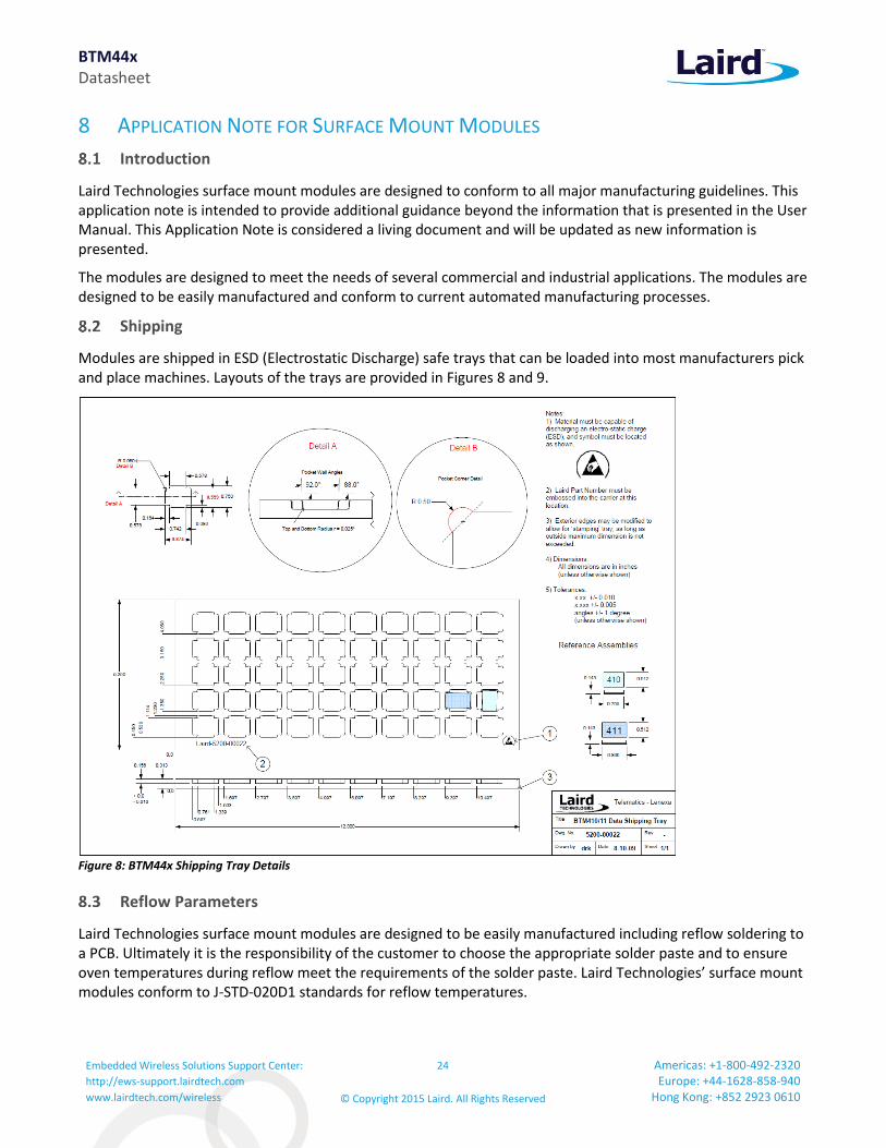
Shipping
Modules are shipped in ESD (Electrostatic Discharge) safe trays that can be loaded into most manufacturers pick and place machines. Layouts of the trays are provided in Figures 8 and 9.
Figure 8: BTM44x Shipping Tray Details
Reflow Parameters
Laird Technologies surface mount modules are designed to be easily manufactured including reflow soldering to a PCB. Ultimately it is the responsibility of the customer to choose the appropriate solder paste and to ensure oven temperatures during reflow meet the requirements of the solder paste. Laird Technologies’ surface mount modules conform to J-STD-020D1 standards for reflow temperatures.

BTM44x Datasheet
Embedded Wireless Solutions Support Center:
http://ews-support.lairdtech.com
www.lairdtech.com/wireless
25
© Copyright 2015 Laird. All Rights Reserved
Americas: +1-800-492-2320 Europe: +44-1628-858-940
Hong Kong: +852 2923 0610
Figure 10: Recommended Reflow Temperature
Temperatures should not exceed the minimums or maximums presented in Table 21.
Table 8: Recommended Maximum and minimum temperatures
Recommended Max & Min's Specification Value Unit
Temperature Inc./Dec. Rate (max) 3 °C / Sec
Temperature Decrease rate (goal) 2-3 °C / Sec
Soak Temp Increase rate (goal) .5 - 1 °C / Sec
Flux Soak Period (Min) 60 Sec
Flux Soak Period (Max) 90 Sec
Flux Soak Temp (Min) 150 °C
Flux Soak Temp (max) 190 °C
Time Above Liquidous (max) 60 Sec
Time Above Liquidous (min) 20 Sec
Time In Target Reflow Range (goal) 30 Sec
Time At Absolute Peak (max) 30 Sec
Liquidous Temperature (SAC305) 217 °C
Lower Target Reflow Temperature 225 °C
Upper Target Reflow Temperature 250 °C
Absolute Peak Temperature 260 °C
IMPORTANT: During reflow, modules should not be above 260°C and not for more than 30 seconds.
BTM44x Datasheet
Embedded Wireless Solutions Support Center:
http://ews-support.lairdtech.com
www.lairdtech.com/wireless
26
© Copyright 2015 Laird. All Rights Reserved
Americas: +1-800-492-2320 Europe: +44-1628-858-940
Hong Kong: +852 2923 0610
9 REFERENCES
[1] “Bluetooth Specification Version 2.1 + EDR [vol3]”, 26 July 2007
http://www.bluetooth.com/Bluetooth/Technology/Building/Specifications/
(click on “Core Specification v2.1 + EDR”)
[2] “Serial Port Profile“ Specification
http://www.bluetooth.com/Bluetooth/Technology/Works/SPP.htm
(link at the bottom of page “Need more? View the Serial Port Profile (SPP)”)
[3] “Bluetooth Assigned Numbers”
http://www.bluetooth.com/Bluetooth/Technology/Building/Specifications/
select “Items per page: ALL”, go to end of page, there click on “Assigned Numbers – Baseband”, for a complete list of Profile UUIDs: click on “Assigned Numbers – Service Discovery”
[4] Class of Device Generator: this link might be helpful for creating a particular CoD
http://bluetooth-pentest.narod.ru/software/bluetooth_class_of_device-service_generator.html
Caution: this tool allows selection of more than one minor device classes, so make sure that only one minor device class is select and verify the result with [3] anyway.
[5] “Bluecore 4 External” Data Sheet, Cambridge Silicon Radio (CSR)
http://www.csrsupport.com (log in or new account required)
[6] “Winbond 681360 Codec Board User Guide”, Ezurio Application Note
[7] “BTM44x AppNote: Getting Started”
[8] “BTM44x AppNote: Firmware Upgrade”
[9] “BTM44x AppNote: Throughput Analysis”
[10] “BTM44x AppNote: Health Device Profile”
[11] “BTM44x AppNote: Latency Optimization”
[12] “BTM44x AppNote: RF Testing”

BTM44x Datasheet
Embedded Wireless Solutions Support Center:
http://ews-support.lairdtech.com
www.lairdtech.com/wireless
27
© Copyright 2015 Laird. All Rights Reserved
Americas: +1-800-492-2320 Europe: +44-1628-858-940
Hong Kong: +852 2923 0610
10 GLOSSARY OF TERMS Term Description
A2DP : Advanced Audio Distribution Profile
ACL : Asynchronous Connection-Oriented Link
ADC : Analogue to Digital Converter
AGHFP : Audio Gateway Hands-Free Profile
AT : Command prefix, ‘Attention’
AVRCP : Audio/Video Remote Control Profile
BISM : Bluetooth Intelligent Serial Module
CoD : Class Of Device (also referred to as “device class”)
Codec : Device capable of encoding / decoding an analogue / digital signal
DAC : Digital to Analogue Converter
DSP : Digital Signal Processor
DUN : Dial-Up Network Profile
EIR : Extended Inquiry Response
eSCO : Enhanced Synchronous Connection Oriented Link (used for Audio)
FTP : File Transfer Profile
GOEP : Generic Object Access Exchange Profile
GPIO : General Purpose Input Output
HF : Hands-free Role of Hands-free Profile (“Hands-free Unit”)
HFG : Audio Gateway Role of Hands-free Profile (“Hands-free Gateway”)
HFP : Hands Free Profile
HID : Human Interface Device Profile
HS : Headset Role of Headset Profile (“Headset”)
HSG : Audio Gateway Role of Headset Profile (“Headset Gateway”)
HSP : Headset Profile
I/O (IO)
: Input/Output
Mic : Microphone
MITM : Man In The Middle
OPP : Object Push Profile
PBAP : Phone Book Access Profile
PT : PASS THROUGH Command
PWM : Pulse Width Modulation
SBC : Sub Band Codec
SCO : Synchronous Connection Oriented Link (used for Audio)
SLC : Service Level Connection
SPP : Serial Port Profile
SSO : Serial Stream Oriented
SSP : Secure Simple Pairing
SUI : SUBUNIT INFO Command
Sxxx : S-Register No. xxx
TDL : Trusted Device List
UART : Universal Asynchronous Receiver / Transmitter
UI : UNIT INFO Command

BTM44x Datasheet
Embedded Wireless Solutions Support Center:
http://ews-support.lairdtech.com
www.lairdtech.com/wireless
28
© Copyright 2015 Laird. All Rights Reserved
Americas: +1-800-492-2320 Europe: +44-1628-858-940
Hong Kong: +852 2923 0610
11 RELATED DOCUMENTS AND FILES
The following additional BTM44x technical documents are also available from the Laird BTM44x product page under the Documentation tab:
Product Brief User Manual Firmware Release Notes Development Kit Schematics
Application Notes
Getting Started Firmware Upgrade Throughput Analysis Health Device Profile Latency Optimization RF Testing