datasheet convenient and full featured. one-box source-and ... · keysight u3606b multimeter i dc...
TRANSCRIPT
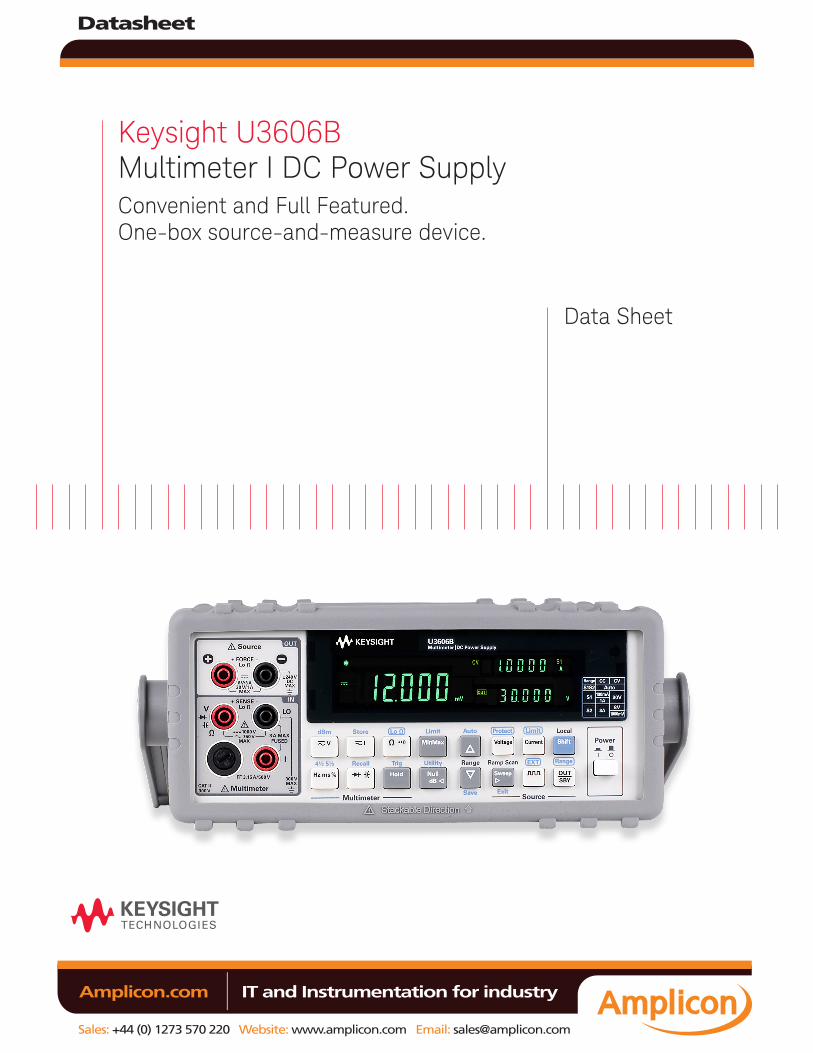
Keysight U3606B Multimeter I DC Power Supply Convenient and Full Featured. One-box source-and-measure device.
Data Sheet
Datasheet
Sales: +44 (0) 1273 570 220 Website: www.amplicon.com Email: [email protected]
IT and Instrumentation for industry Amplicon.com
Introduction
Features – Combination of a 5.5 digit digital multimeter and 30-W power supply in a single unit – 10 DMM measurements, including 4-wire miliohm measurement – 8 built-in math functions – OVP and OCP for load protection – Ramp and scan function, and built in square-wave output – USB 2.0 interface and GPIB connectivity – Kensington lock slot for security
Datasheet
Sales: +44 (0) 1273 570 220 Website: www.amplicon.com Email: [email protected]
IT and Instrumentation for industry Amplicon.com
Convenient two instruments in one boxLooking for a one-box source-and-measure device to meet your measurement needs? The Keysight Technologies U3606B Multimeter | DC Power supply is a full-featured 5.5 digit digital multimeter (DMM) that comes with a built-in 30-W power supply offering a compact footprint enabling you to get work done faster and easier. Being capable of powering up the DUT while measures Voltage and Current simultaneously, it enables users to perform two test functions within the same unit.
The U3606B is carefully thought out for your convenience and ease when operating. The convenient two instruments in a box concept is space and cost efficient, as less space is needed to accommodate one device instead of two. Also the U3606B is lightweight enabling easy portability — lighter than both DMM and power supply combined, making it ideal for various industry such as education, commercial electronics, semiconductors, sensors and research and development.
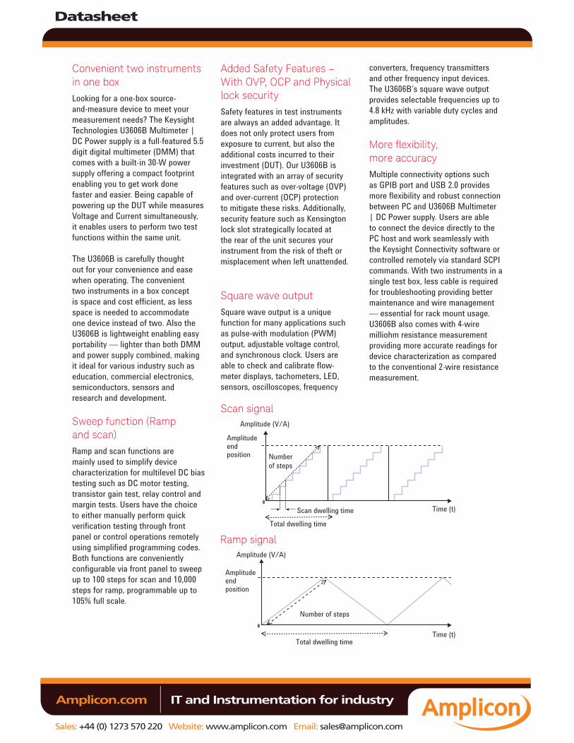
Sweep function (Ramp and scan)Ramp and scan functions are mainly used to simplify device characterization for multilevel DC bias testing such as DC motor testing, transistor gain test, relay control and margin tests. Users have the choice to either manually perform quick verification testing through front panel or control operations remotely using simplified programming codes. Both functions are conveniently configurable via front panel to sweep up to 100 steps for scan and 10,000 steps for ramp, programmable up to 105% full scale.
Added Safety Features – With OVP, OCP and Physical lock securitySafety features in test instruments are always an added advantage. It does not only protect users from exposure to current, but also the additional costs incurred to their investment (DUT). Our U3606B is integrated with an array of security features such as over-voltage (OVP) and over-current (OCP) protection to mitigate these risks. Additionally, security feature such as Kensington lock slot strategically located at the rear of the unit secures your instrument from the risk of theft or misplacement when left unattended.
Square wave outputSquare wave output is a unique function for many applications such as pulse-with modulation (PWM) output, adjustable voltage control, and synchronous clock. Users are able to check and calibrate flow-meter displays, tachometers, LED, sensors, oscilloscopes, frequency
converters, frequency transmitters and other frequency input devices. The U3606B’s square wave output provides selectable frequencies up to 4.8 kHz with variable duty cycles and amplitudes.
More flexibility, more accuracyMultiple connectivity options such as GPIB port and USB 2.0 provides more flexibility and robust connection between PC and U3606B Multimeter | DC Power supply. Users are able to connect the device directly to the PC host and work seamlessly with the Keysight Connectivity software or controlled remotely via standard SCPI commands. With two instruments in a single test box, less cable is required for troubleshooting providing better maintenance and wire management — essential for rack mount usage. U3606B also comes with 4-wire milliohm resistance measurement providing more accurate readings for device characterization as compared to the conventional 2-wire resistance measurement.
Scan signal
Ramp signal
Amplitude (V/A)
Amplitude (V/A)
Amplitude end position
Amplitude end position
Scan dwelling time
Total dwelling time
Total dwelling time
Time (t)
Time (t)
Number of steps
Number of steps
Datasheet
Sales: +44 (0) 1273 570 220 Website: www.amplicon.com Email: [email protected]
IT and Instrumentation for industry Amplicon.com
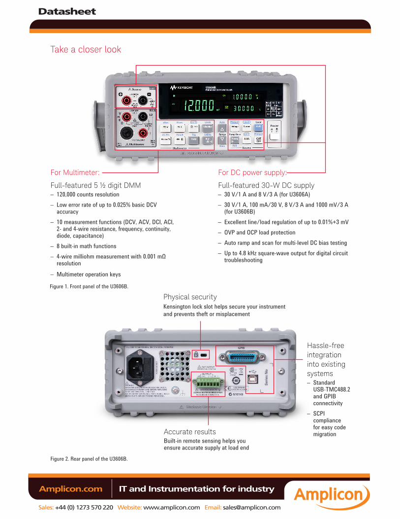
Take a closer look
For DC power supply:
Full-featured 30-W DC supply– 30 V/1 A and 8 V/3 A (for U3606A)– 30 V/1 A, 100 mA/30 V, 8 V/3 A and 1000 mV/3 A
(for U3606B)– Excellent line/load regulation of up to 0.01%+3 mV– OVP and OCP load protection– Auto ramp and scan for multi-level DC bias testing– Up to 4.8 kHz square-wave output for digital circuit
troubleshooting
Figure 1. Front panel of the U3606B.
Figure 2. Rear panel of the U3606B.
Hassle-free integration into existing systems– Standard
USB-TMC488.2 and GPIB connectivity
– SCPI compliance for easy code migrationAccurate results
Built-in remote sensing helps you ensure accurate supply at load end
Physical securityKensington lock slot helps secure your instrument and prevents theft or misplacement
For Multimeter:
Full-featured 5 ½ digit DMM– 120,000 counts resolution– Low error rate of up to 0.025% basic DCV
accuracy– 10 measurement functions (DCV, ACV, DCI, ACI,
2- and 4-wire resistance, frequency, continuity, diode, capacitance)
– 8 built-in math functions– 4-wire milliohm measurement with 0.001 mΩ
resolution
– Multimeter operation keys
Datasheet
Sales: +44 (0) 1273 570 220 Website: www.amplicon.com Email: [email protected]
IT and Instrumentation for industry Amplicon.com
Digital multimeter specifications
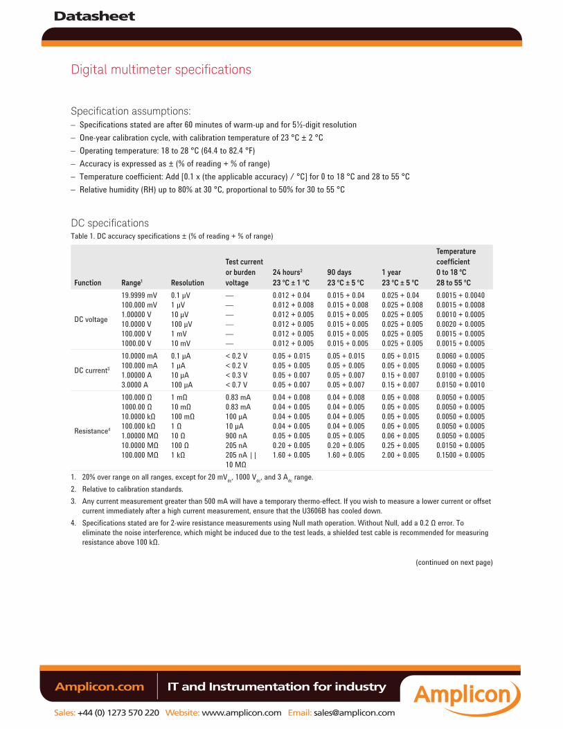
Specification assumptions:– Specifications stated are after 60 minutes of warm-up and for 5½-digit resolution– One-year calibration cycle, with calibration temperature of 23 °C ± 2 °C– Operating temperature: 18 to 28 °C (64.4 to 82.4 °F)– Accuracy is expressed as ± (% of reading + % of range) – Temperature coefficient: Add [0.1 x (the applicable accuracy) / °C] for 0 to 18 °C and 28 to 55 °C– Relative humidity (RH) up to 80% at 30 °C, proportional to 50% for 30 to 55 °C
DC specificationsTable 1. DC accuracy specifications ± (% of reading + % of range)
Function Range1 Resolution
Test current or burden voltage
24 hours2 23 ºC ± 1 ºC
90 days 23 ºC ± 5 ºC
1 year 23 ºC ± 5 ºC
Temperature coefficient 0 to 18 ºC 28 to 55 ºC
DC voltage
19.9999 mV 100.000 mV 1.00000 V 10.0000 V 100.000 V 1000.00 V
0.1 μV 1 μV 10 μV 100 μV 1 mV 10 mV
— — — — — —
0.012 + 0.04 0.012 + 0.008 0.012 + 0.005 0.012 + 0.005 0.012 + 0.005 0.012 + 0.005
0.015 + 0.04 0.015 + 0.008 0.015 + 0.005 0.015 + 0.005 0.015 + 0.005 0.015 + 0.005
0.025 + 0.04 0.025 + 0.008 0.025 + 0.005 0.025 + 0.005 0.025 + 0.005 0.025 + 0.005
0.0015 + 0.0040 0.0015 + 0.0008 0.0010 + 0.0005 0.0020 + 0.0005 0.0015 + 0.0005 0.0015 + 0.0005
DC current3
10.0000 mA 100.000 mA 1.00000 A 3.0000 A
0.1 μA 1 μA 10 μA 100 μA
< 0.2 V < 0.2 V < 0.3 V < 0.7 V
0.05 + 0.015 0.05 + 0.005 0.05 + 0.007 0.05 + 0.007
0.05 + 0.015 0.05 + 0.005 0.05 + 0.007 0.05 + 0.007
0.05 + 0.015 0.05 + 0.005 0.15 + 0.007 0.15 + 0.007
0.0060 + 0.0005 0.0060 + 0.0005 0.0100 + 0.0005 0.0150 + 0.0010
Resistance4
100.000 Ω1000.00 Ω10.0000 kΩ100.000 kΩ1.00000 MΩ10.0000 MΩ100.000 MΩ
1 mΩ 10 mΩ 100 mΩ 1 Ω 10 Ω 100 Ω 1 kΩ
0.83 mA0.83 mA100 µA10 µA900 nA205 nA205 nA || 10 MΩ
0.04 + 0.0080.04 + 0.0050.04 + 0.0050.04 + 0.0050.05 + 0.0050.20 + 0.0051.60 + 0.005
0.04 + 0.0080.04 + 0.0050.04 + 0.0050.04 + 0.0050.05 + 0.0050.20 + 0.0051.60 + 0.005
0.05 + 0.0080.05 + 0.0050.05 + 0.0050.05 + 0.0050.06 + 0.0050.25 + 0.0052.00 + 0.005
0.0050 + 0.00050.0050 + 0.00050.0050 + 0.00050.0050 + 0.00050.0050 + 0.00050.0150 + 0.00050.1500 + 0.0005
1. 20% over range on all ranges, except for 20 mVdc, 1000 Vdc, and 3 Adc range.2. Relative to calibration standards.3. Any current measurement greater than 500 mA will have a temporary thermo-effect. If you wish to measure a lower current or offset
current immediately after a high current measurement, ensure that the U3606B has cooled down.4. Specifications stated are for 2-wire resistance measurements using Null math operation. Without Null, add a 0.2 Ω error. To
eliminate the noise interference, which might be induced due to the test leads, a shielded test cable is recommended for measuring resistance above 100 kΩ.
(continued on next page)
Datasheet
Sales: +44 (0) 1273 570 220 Website: www.amplicon.com Email: [email protected]
IT and Instrumentation for industry Amplicon.com
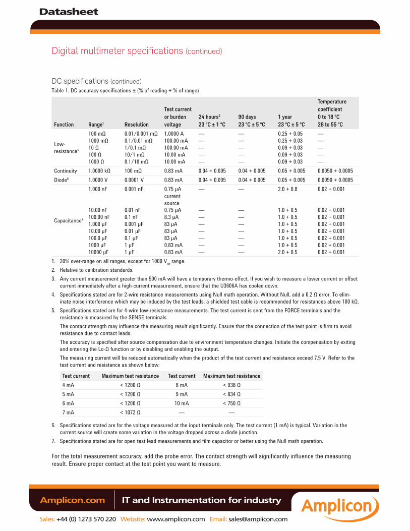
Digital multimeter specifications (continued)
DC specifications (continued)Table 1. DC accuracy specifications ± (% of reading + % of range)
Function Range1 Resolution
Test current or burden voltage
24 hours2 23 ºC ± 1 ºC
90 days 23 ºC ± 5 ºC
1 year 23 ºC ± 5 ºC
Temperature coefficient 0 to 18 ºC 28 to 55 ºC
Low-resistance5
100 mΩ 1000 mΩ 10 Ω 100 Ω 1000 Ω
0.01/0.001 mΩ 0.1/0.01 mΩ 1/0.1 mΩ 10/1 mΩ 0.1/10 mΩ
1,0000 A 100.00 mA 100.00 mA 10.00 mA 10.00 mA
— — — — —
— — — — —
0.25 + 0.05 0.25 + 0.03 0.09 + 0.03 0.09 + 0.03 0.09 + 0.03
— — — — —
Continuity 1.0000 kΩ 100 mΩ 0.83 mA 0.04 + 0.005 0.04 + 0.005 0.05 + 0.005 0.0050 + 0.0005Diode6 1.0000 V 0.0001 V 0.83 mA 0.04 + 0.005 0.04 + 0.005 0.05 + 0.005 0.0050 + 0.0005
Capacitance7
1.000 nF
10.00 nF100.00 nF1.000 µF10.00 µF100.0 µF1000 µF10000 µF
0.001 nF
0.01 nF 0.1 nF 0.001 μF 0.01 μF 0.1 μF 1 μF 1 μF
0.75 µA current source0.75 µA8.3 µA83 µA83 µA83 µA0.83 mA0.83 mA
—
———————
—
———————
2.0 + 0.8
1.0 + 0.51.0 + 0.51.0 + 0.51.0 + 0.51.0 + 0.51.0 + 0.52.0 + 0.5
0.02 + 0.001
0.02 + 0.0010.02 + 0.0010.02 + 0.0010.02 + 0.0010.02 + 0.0010.02 + 0.0010.02 + 0.001
1. 20% over-range on all ranges, except for 1000 Vdc range.2. Relative to calibration standards.3. Any current measurement greater than 500 mA will have a temporary thermo-effect. If you wish to measure a lower current or offset
current immediately after a high-current measurement, ensure that the U3606A has cooled down.4. Specifications stated are for 2-wire resistance measurements using Null math operation. Without Null, add a 0.2 Ω error. To elim-
inate noise interference which may be induced by the test leads, a shielded test cable is recommended for resistances above 100 kΩ.5. Specifications stated are for 4-wire low-resistance measurements. The test current is sent from the FORCE terminals and the
resistance is measured by the SENSE terminals.The contact strength may influence the measuring result significantly. Ensure that the connection of the test point is firm to avoid resistance due to contact leads.The accuracy is specified after source compensation due to environment temperature changes. Initiate the compensation by exiting and entering the Lo-Ω function or by disabling and enabling the output.The measuring current will be reduced automatically when the product of the test current and resistance exceed 7.5 V. Refer to the test current and resistance as shown below:
Test current Maximum test resistance Test current Maximum test resistance
4 mA < 1200 Ω 8 mA < 938 Ω5 mA < 1200 Ω 9 mA < 834 Ω6 mA < 1200 Ω 10 mA < 750 Ω7 mA < 1072 Ω — —
6. Specifications stated are for the voltage measured at the input terminals only. The test current (1 mA) is typical. Variation in the current source will create some variation in the voltage dropped across a diode junction.
7. Specifications stated are for open test lead measurements and film capacitor or better using the Null math operation.
For the total measurement accuracy, add the probe error. The contact strength will significantly influence the measuring result. Ensure proper contact at the test point you want to measure.
Datasheet
Sales: +44 (0) 1273 570 220 Website: www.amplicon.com Email: [email protected]
IT and Instrumentation for industry Amplicon.com
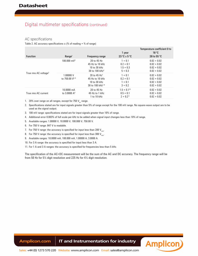
Digital multimeter specifications (continued)
AC specificationsTable 2. AC accuracy specifications ± (% of reading + % of range)
Function Range1 Frequency range1 year
23 ºC ± 5 ºC
Temperature coefficient 0 to 18 ºC
28 to 55 ºC
True rms AC voltage2
100.000 mV3 20 to 45 Hz45 Hz to 10 kHz
10 to 30 kHz30 to 100 kHz4
1 + 0.10.2 + 0.11.5 + 0.35 + 0.3
0.02 + 0.020.02 + 0.020.02 + 0.020.02 + 0.02
1.00000 V to 750.00 V5, 6
20 to 45 Hz7
45 Hz to 10 kHz10 to 30 kHz
30 to 100 kHz4, 8
1 + 0.10.2 + 0.11 + 0.13 + 0.2
0.02 + 0.020.02 + 0.020.02 + 0.020.02 + 0.02
True rms AC current10.0000 mA to 3.0000 A9
20 to 45 Hz45 Hz to 1 kHz
1 to 10 kHz
1.5 + 0.110
0.5 + 0.12 + 0.211
0.02 + 0.020.02 + 0.020.02 + 0.02
1. 20% over range on all ranges, except for 750 Vac range.2. Specifications stated are for input signals greater than 5% of range except for the 100 mV range. No square-wave output are to be
used as the signal output.3. 100 mV range: specifications stated are for input signals greater than 10% of range.4. Additional error 0.003% of full scale per kHz to be added when signal input changes less than 10% of range.5. Available ranges: 1.00000 V, 10.0000 V, 100.000 V, 750.00 V.6. For 750 V range: 847 V is readable.7. For 750 V range: the accuracy is specified for input less than 200 Vrms.8. For 750 V range: the accuracy is specified for input less than 300 Vrms.9. Available ranges: 10.0000 mA, 100.000 mA, 1.00000 A, 3.0000 A.10. For 3 A range: the accuracy is specified for input less than 3 A.11. For 1 A and 3 A ranges: the accuracy is specified for frequencies less than 5 kHz.
The specification of the AC+DC measurement will be the sum of the AC and DC accuracy. The frequency range will be from 50 Hz for 5½ digit resolution and 225 Hz for 4½ digit resolution.
Datasheet
Sales: +44 (0) 1273 570 220 Website: www.amplicon.com Email: [email protected]
IT and Instrumentation for industry Amplicon.com

Digital multimeter specifications (continued)
Frequency specificationsTable 3. Frequency accuracy specifications ± (% of reading + % of range)
Function Range Frequency range1 year
23 ºC ± 5 ºC
Temperature coefficient 0 to 18 ºC
28 to 55 ºC
Frequency1
Voltage path: 100 mV to 750 V
< 2 Hz < 20 Hz
20 Hz to 100 kHz 100 to 300 kHz
0.18 + 0.003 0.04 + 0.003 0.02 + 0.003 0.02 + 0.003
0.005 0.005 0.005 0.005
Current path: 10 mA to 3 A
< 2 Hz < 20 Hz
20 Hz to 10 kHz
0.18 + 0.003 0.04 + 0.003 0.02 + 0.003
0.005 0.005 0.005
1. For 100 mV and 1 V ranges, the measurable frequency is up to 1 MHz at 0.5 V signal. Minimum input frequency is 1 Hz.
All frequency counters are susceptible to errors when measuring low-voltage, low-frequency signals. Shielding inputs from external noise pickup is critical for minimizing measurement errors.
Table 4. Frequency sensitivity for voltage measurement
Input range1
Minimum sensitivity (rms sine wave)
20 Hz to 100 kHz 100 to 300 kHz 300 kHz to 1 MHz
100 mV 1.0 V 10 V 100 V 750 V
50 mV 100 mV
1 V 10 V 100 V
50 mV 120 mV 1.2 V 12 V
–
0.5 V 0.5 V — — —
1. Maximum input for specified accuracy = 10 × range or 750 Vrms or 1000 Vdc.
Table 5. Frequency sensitivity for current measurement
Input range
Minimum sensitivity (rms sine wave)
20 Hz to 10 kHz
10 mA100 mA1.000 A3 A
1 mA10 mA100 mA300 mA
Datasheet
Sales: +44 (0) 1273 570 220 Website: www.amplicon.com Email: [email protected]
IT and Instrumentation for industry Amplicon.com

Duty cycle and pulse width specificationsTable 6. Duty cycle and pulse width resolution and accuracy
Function Range Resolution Accuracy of full scale
Duty cycle 100.000%1 0.001% 0.3% + 0.2% per kHz
Pulse width 199.999 ms2 1999.99 ms2
0.001 ms 0.01 ms
Duty cycle/frequency Duty cycle/frequency
1. The range is from 10 µs × frequency × 100% to [1 – (10 µs × frequency)] × 100%. For example, a 1 kHz signal can be measured from 1% to 99%.
2. The positive or negative pulse width must be greater than 10 µs. The range of the pulse width is determined by the frequency of the signal.
Operating specificationsTable 7. Reading speed (typical)1
Function RateReading speed2
(readings/second)
Reading speed over USB3
(readings/second)
Reading speed over GPIB4
(readings/second)
DC voltage (10 V)
Slow (5½ digits) Fast (4½ digits)
17 70
8 23
8 22
DC current (1 A)
Slow (5½ digits) Fast (4½ digits)
17 70
8 26
8 24
AC voltage (10 V at 1 kHz)
Slow (5½ digits) Fast (4½ digits)
17 70
8 23
8 22
AC current (1 A at 1 kHz)
Slow (5½ digits) Fast (4½ digits)
17 70
8 26
8 24
AC + DC voltage (10 V at 1 kHz)
Slow (5½ digits) Fast (4½ digits)
4 17
2.9 10
2.9 10
AC + DC current (1 A at 1 kHz)
Slow (5½ digits) Fast (4½ digits)
4 17
2.9 10
2.9 10
Resistance (100 kΩ)
Slow (5½ digits) Fast (4½ digits)
17 70
8 22
8 22
Lo-Ω(1 kΩ)
Slow (5½ digits) Fast (4½ digits)
17 70
0.8 0.8
0.8 0.8
Capacitance (10 µF)
Slow/Fast (3½ digits) 5 1.4 1.4
Diode(1 V)
Slow/Fast (4½ digits) 70 26 23
Frequency (voltage path at 10 V, 1 kHz)
Slow (5½ digits) Fast (4½ digits)
9 9
8 8
8 8
Frequency (current path at 1 A, 1 kHz)
Slow (5½ digit) Fast (4½ digit)
9 9
8 8
8 8
1. Based on an average of 500 readings.2. Reading rate of the A/D converter.3. Number of measurements per second that can be read through USB using SCPI “READ?” command.4. Number of measurements per second that can be read through GPIB using SCPI “READ?” command.
Digital multimeter specifications (continued)
Datasheet
Sales: +44 (0) 1273 570 220 Website: www.amplicon.com Email: [email protected]
IT and Instrumentation for industry Amplicon.com
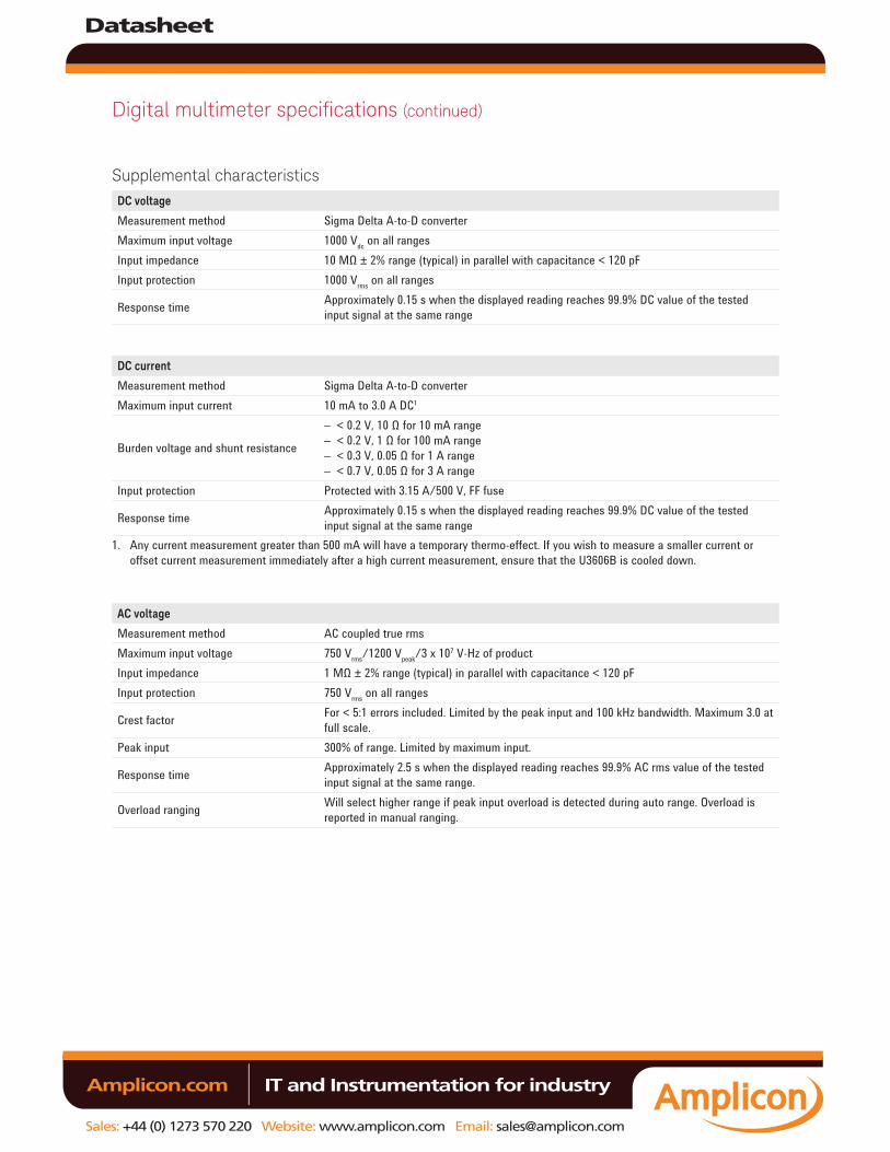
Digital multimeter specifications (continued)
Supplemental characteristicsDC voltage
Measurement method Sigma Delta A-to-D converterMaximum input voltage 1000 Vdc on all rangesInput impedance 10 MΩ ± 2% range (typical) in parallel with capacitance < 120 pFInput protection 1000 Vrms on all ranges
Response time Approximately 0.15 s when the displayed reading reaches 99.9% DC value of the tested input signal at the same range
DC current
Measurement method Sigma Delta A-to-D converterMaximum input current 10 mA to 3.0 A DC1
Burden voltage and shunt resistance
– < 0.2 V, 10 Ω for 10 mA range– < 0.2 V, 1 Ω for 100 mA range– < 0.3 V, 0.05 Ω for 1 A range– < 0.7 V, 0.05 Ω for 3 A range
Input protection Protected with 3.15 A/500 V, FF fuse
Response time Approximately 0.15 s when the displayed reading reaches 99.9% DC value of the tested input signal at the same range
1. Any current measurement greater than 500 mA will have a temporary thermo-effect. If you wish to measure a smaller current or offset current measurement immediately after a high current measurement, ensure that the U3606B is cooled down.
AC voltage
Measurement method AC coupled true rmsMaximum input voltage 750 Vrms/1200 Vpeak/3 x 107 V-Hz of productInput impedance 1 MΩ ± 2% range (typical) in parallel with capacitance < 120 pFInput protection 750 Vrms on all ranges
Crest factor For < 5:1 errors included. Limited by the peak input and 100 kHz bandwidth. Maximum 3.0 at full scale.
Peak input 300% of range. Limited by maximum input.
Response time Approximately 2.5 s when the displayed reading reaches 99.9% AC rms value of the tested input signal at the same range.
Overload ranging Will select higher range if peak input overload is detected during auto range. Overload is reported in manual ranging.
Datasheet
Sales: +44 (0) 1273 570 220 Website: www.amplicon.com Email: [email protected]
IT and Instrumentation for industry Amplicon.com
Digital multimeter specifications (continued)
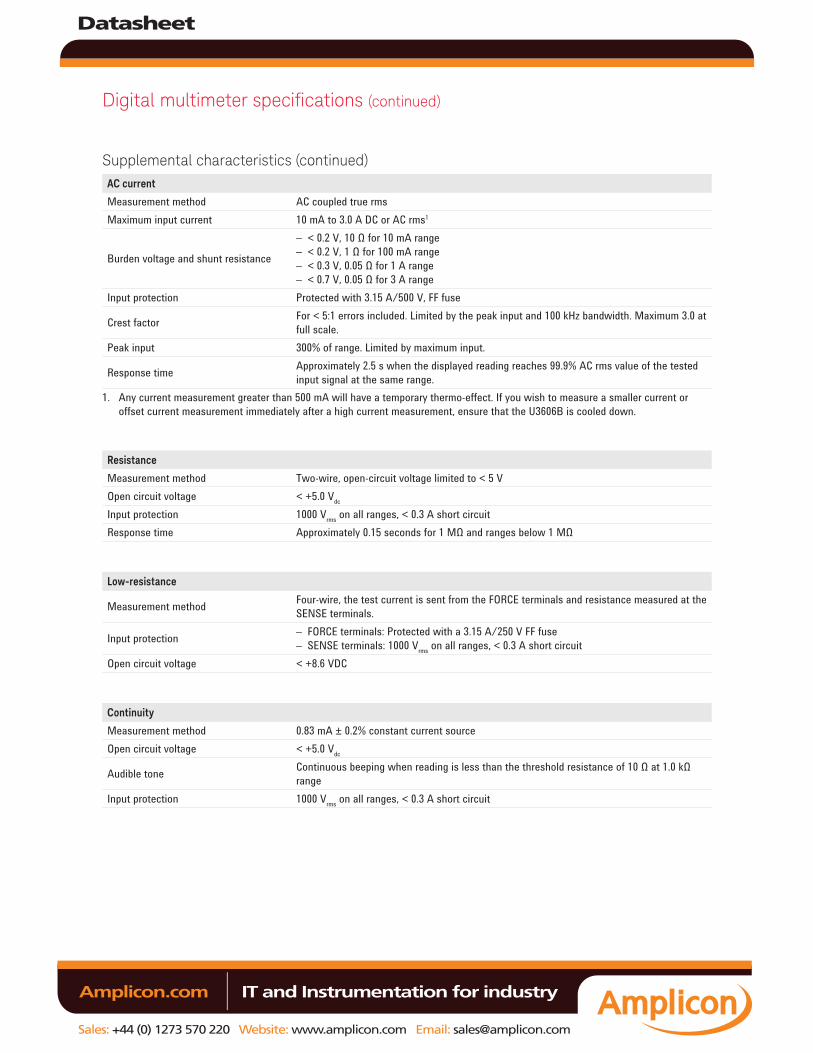
Supplemental characteristics (continued)AC current
Measurement method AC coupled true rmsMaximum input current 10 mA to 3.0 A DC or AC rms1
Burden voltage and shunt resistance
– < 0.2 V, 10 Ω for 10 mA range– < 0.2 V, 1 Ω for 100 mA range– < 0.3 V, 0.05 Ω for 1 A range– < 0.7 V, 0.05 Ω for 3 A range
Input protection Protected with 3.15 A/500 V, FF fuse
Crest factor For < 5:1 errors included. Limited by the peak input and 100 kHz bandwidth. Maximum 3.0 at full scale.
Peak input 300% of range. Limited by maximum input.
Response time Approximately 2.5 s when the displayed reading reaches 99.9% AC rms value of the tested input signal at the same range.
1. Any current measurement greater than 500 mA will have a temporary thermo-effect. If you wish to measure a smaller current or offset current measurement immediately after a high current measurement, ensure that the U3606B is cooled down.
Resistance
Measurement method Two-wire, open-circuit voltage limited to < 5 VOpen circuit voltage < +5.0 Vdc
Input protection 1000 Vrms on all ranges, < 0.3 A short circuitResponse time Approximately 0.15 seconds for 1 MΩ and ranges below 1 MΩ
Low-resistance
Measurement method Four-wire, the test current is sent from the FORCE terminals and resistance measured at the SENSE terminals.
Input protection – FORCE terminals: Protected with a 3.15 A/250 V FF fuse– SENSE terminals: 1000 Vrms on all ranges, < 0.3 A short circuit
Open circuit voltage < +8.6 VDC
Continuity
Measurement method 0.83 mA ± 0.2% constant current sourceOpen circuit voltage < +5.0 Vdc
Audible tone Continuous beeping when reading is less than the threshold resistance of 10 Ω at 1.0 kΩ range
Input protection 1000 Vrms on all ranges, < 0.3 A short circuit
Datasheet
Sales: +44 (0) 1273 570 220 Website: www.amplicon.com Email: [email protected]
IT and Instrumentation for industry Amplicon.com
Digital multimeter specifications (continued)
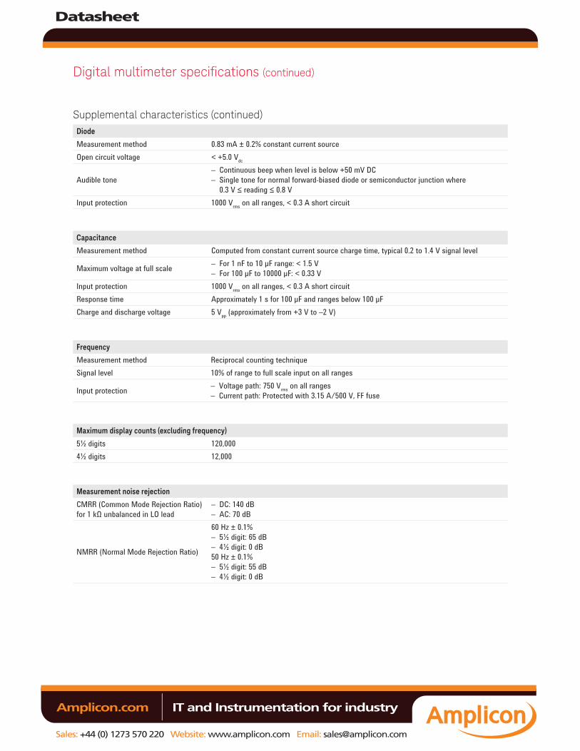
Supplemental characteristics (continued)Diode
Measurement method 0.83 mA ± 0.2% constant current sourceOpen circuit voltage < +5.0 Vdc
Audible tone– Continuous beep when level is below +50 mV DC– Single tone for normal forward-biased diode or semiconductor junction where
0.3 V ≤ reading ≤ 0.8 VInput protection 1000 Vrms on all ranges, < 0.3 A short circuit
Capacitance
Measurement method Computed from constant current source charge time, typical 0.2 to 1.4 V signal level
Maximum voltage at full scale – For 1 nF to 10 µF range: < 1.5 V– For 100 µF to 10000 µF: < 0.33 V
Input protection 1000 Vrms on all ranges, < 0.3 A short circuitResponse time Approximately 1 s for 100 µF and ranges below 100 µFCharge and discharge voltage 5 Vpp (approximately from +3 V to –2 V)
Frequency
Measurement method Reciprocal counting techniqueSignal level 10% of range to full scale input on all ranges
Input protection – Voltage path: 750 Vrms on all ranges– Current path: Protected with 3.15 A/500 V, FF fuse
Maximum display counts (excluding frequency)
5½ digits 120,0004½ digits 12,000
Measurement noise rejection
CMRR (Common Mode Rejection Ratio) for 1 kΩ unbalanced in LO lead
– DC: 140 dB– AC: 70 dB
NMRR (Normal Mode Rejection Ratio)
60 Hz ± 0.1%– 5½ digit: 65 dB– 4½ digit: 0 dB50 Hz ± 0.1%– 5½ digit: 55 dB– 4½ digit: 0 dB
Datasheet
Sales: +44 (0) 1273 570 220 Website: www.amplicon.com Email: [email protected]
IT and Instrumentation for industry Amplicon.com
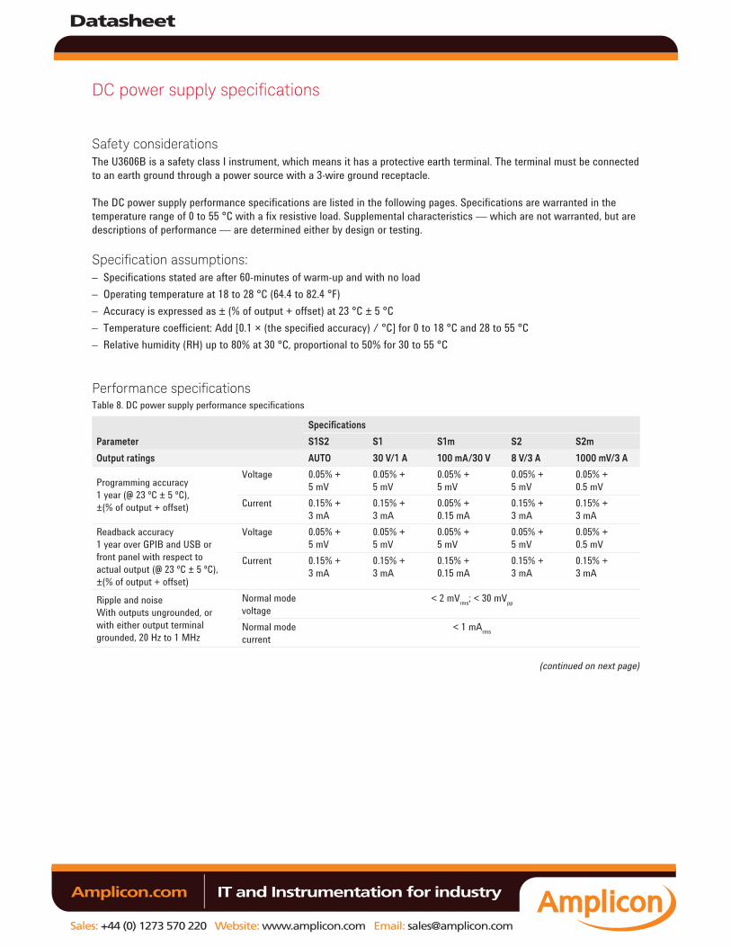
DC power supply specifications
Safety considerations The U3606B is a safety class I instrument, which means it has a protective earth terminal. The terminal must be connected to an earth ground through a power source with a 3-wire ground receptacle.
The DC power supply performance specifications are listed in the following pages. Specifications are warranted in the temperature range of 0 to 55 °C with a fix resistive load. Supplemental characteristics — which are not warranted, but are descriptions of performance — are determined either by design or testing.
Specification assumptions:– Specifications stated are after 60-minutes of warm-up and with no load– Operating temperature at 18 to 28 °C (64.4 to 82.4 °F)– Accuracy is expressed as ± (% of output + offset) at 23 °C ± 5 °C– Temperature coefficient: Add [0.1 × (the specified accuracy) / °C] for 0 to 18 °C and 28 to 55 °C – Relative humidity (RH) up to 80% at 30 °C, proportional to 50% for 30 to 55 °C
Performance specificationsTable 8. DC power supply performance specifications
Parameter
Specifications
S1S2 S1 S1m S2 S2m
Output ratings AUTO 30 V/1 A 100 mA/30 V 8 V/3 A 1000 mV/3 A
Programming accuracy 1 year (@ 23 ºC ± 5 ºC), ±(% of output + offset)
Voltage 0.05% + 5 mV
0.05% + 5 mV
0.05% + 5 mV
0.05% + 5 mV
0.05% + 0.5 mV
Current 0.15% + 3 mA
0.15% + 3 mA
0.05% + 0.15 mA
0.15% + 3 mA
0.15% + 3 mA
Readback accuracy 1 year over GPIB and USB or front panel with respect to actual output (@ 23 ºC ± 5 ºC), ±(% of output + offset)
Voltage 0.05% + 5 mV
0.05% + 5 mV
0.05% + 5 mV
0.05% + 5 mV
0.05% + 0.5 mV
Current 0.15% + 3 mA
0.15% + 3 mA
0.15% + 0.15 mA
0.15% + 3 mA
0.15% + 3 mA
Ripple and noise With outputs ungrounded, or with either output terminal grounded, 20 Hz to 1 MHz
Normal mode voltage
< 2 mVrms; < 30 mVpp
Normal mode current
< 1 mArms
(continued on next page)
Datasheet
Sales: +44 (0) 1273 570 220 Website: www.amplicon.com Email: [email protected]
IT and Instrumentation for industry Amplicon.com
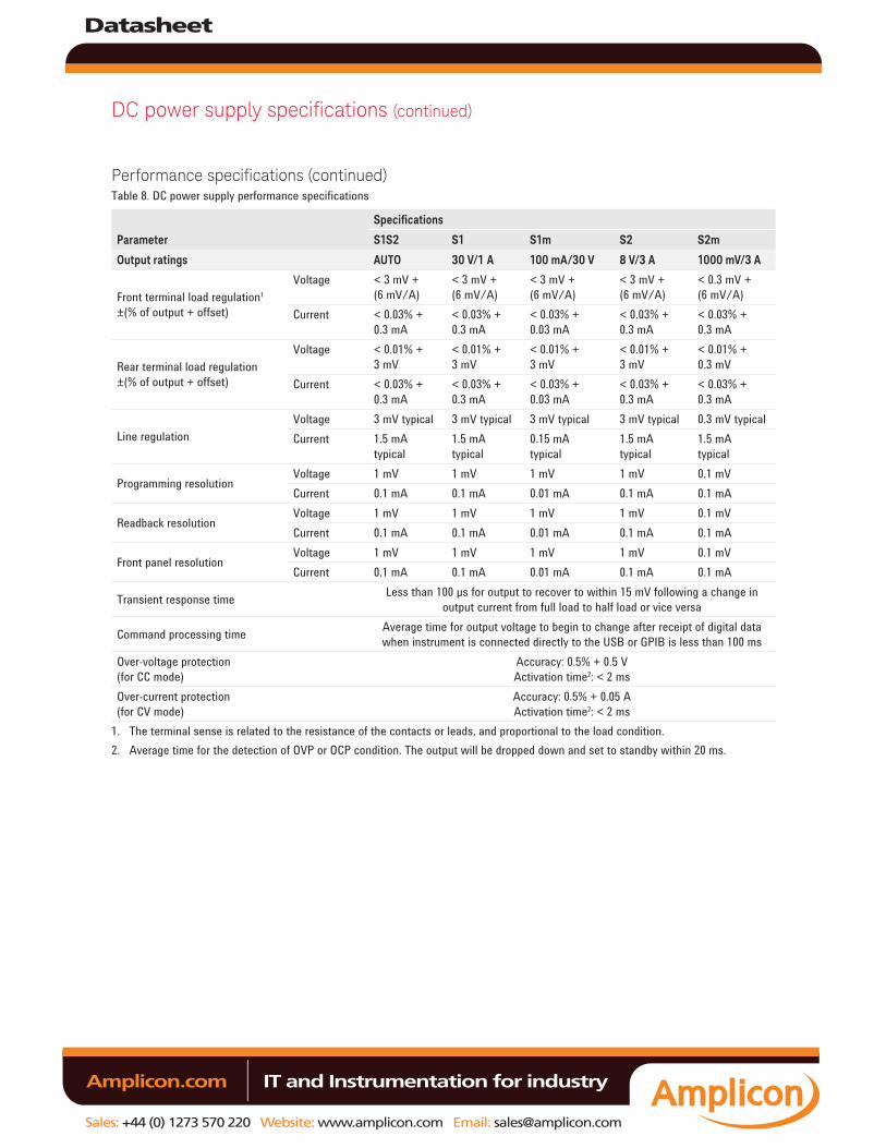
DC power supply specifications (continued)
Performance specifications (continued)Table 8. DC power supply performance specifications
Parameter
Specifications
S1S2 S1 S1m S2 S2m
Output ratings AUTO 30 V/1 A 100 mA/30 V 8 V/3 A 1000 mV/3 A
Front terminal load regulation1 ±(% of output + offset)
Voltage < 3 mV + (6 mV/A)
< 3 mV + (6 mV/A)
< 3 mV + (6 mV/A)
< 3 mV + (6 mV/A)
< 0.3 mV + (6 mV/A)
Current < 0.03% + 0.3 mA
< 0.03% + 0.3 mA
< 0.03% + 0.03 mA
< 0.03% + 0.3 mA
< 0.03% + 0.3 mA
Rear terminal load regulation ±(% of output + offset)
Voltage < 0.01% + 3 mV
< 0.01% + 3 mV
< 0.01% + 3 mV
< 0.01% + 3 mV
< 0.01% + 0.3 mV
Current < 0.03% + 0.3 mA
< 0.03% + 0.3 mA
< 0.03% + 0.03 mA
< 0.03% + 0.3 mA
< 0.03% + 0.3 mA
Line regulationVoltage 3 mV typical 3 mV typical 3 mV typical 3 mV typical 0.3 mV typicalCurrent 1.5 mA
typical1.5 mA typical
0.15 mA typical
1.5 mA typical
1.5 mA typical
Programming resolutionVoltage 1 mV 1 mV 1 mV 1 mV 0.1 mVCurrent 0.1 mA 0.1 mA 0.01 mA 0.1 mA 0.1 mA
Readback resolutionVoltage 1 mV 1 mV 1 mV 1 mV 0.1 mVCurrent 0.1 mA 0.1 mA 0.01 mA 0.1 mA 0.1 mA
Front panel resolutionVoltage 1 mV 1 mV 1 mV 1 mV 0.1 mVCurrent 0.1 mA 0.1 mA 0.01 mA 0.1 mA 0.1 mA
Transient response time Less than 100 µs for output to recover to within 15 mV following a change in output current from full load to half load or vice versa
Command processing time Average time for output voltage to begin to change after receipt of digital data when instrument is connected directly to the USB or GPIB is less than 100 ms
Over-voltage protection (for CC mode)
Accuracy: 0.5% + 0.5 VActivation time2: < 2 ms
Over-current protection (for CV mode)
Accuracy: 0.5% + 0.05 AActivation time2: < 2 ms
1. The terminal sense is related to the resistance of the contacts or leads, and proportional to the load condition.2. Average time for the detection of OVP or OCP condition. The output will be dropped down and set to standby within 20 ms.
Datasheet
Sales: +44 (0) 1273 570 220 Website: www.amplicon.com Email: [email protected]
IT and Instrumentation for industry Amplicon.com
DC power supply specifications (continued)
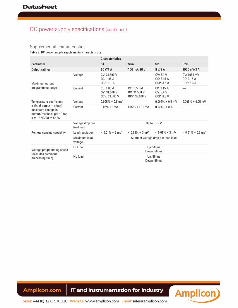
Supplemental characteristicsTable 9. DC power supply supplemental characteristics
Parameter
Characteristics
S1 S1m S2 S2m
Output ratings 30 V/1 A 100 mA/30 V 8 V/3 A 1000 mV/3 A
Maximum output programming range
Voltage CV: 31.500 VOC: 1.05 AOCP: 1.1 A
— CV: 8.4 VOC: 3.15 AOCP: 3.3 A
CV: 1050 mVOC: 3.15 AOCP: 3.3 A
Current CC: 1.05 AOV: 31.500 VOCP: 33.000 V
CC: 105 mAOV: 31.500 VOCP: 33.000 V
CC: 3.15 AOV: 8.4 VOCP: 8.8 V
—
Temperature coefficient ± (% of output + offset) maximum change in output/readback per °C for 0 to 18 ºC/28 to 55 ºC
Voltage 0.005% + 0.5 mV — 0.005% + 0.5 mV 0.005% + 0.05 mVCurrent 0.02% +1 mA 0.02% +0.01 mA 0.02% +1 mA —
Remote sensing capability
Voltage drop per load lead
Up to 0.75 V
Load regulation < 0.01% + 3 mV < 0.01% + 3 mV < 0.01% + 3 mV < 0.01% + 0.3 mVMaximum load voltage
Subtract voltage drop per load lead
Voltage programming speed (excludes command processing time)
Full load Up: 50 msDown: 50 ms
No load Up: 50 msDown: 50 ms
Datasheet
Sales: +44 (0) 1273 570 220 Website: www.amplicon.com Email: [email protected]
IT and Instrumentation for industry Amplicon.com
DC power supply specifications (continued)
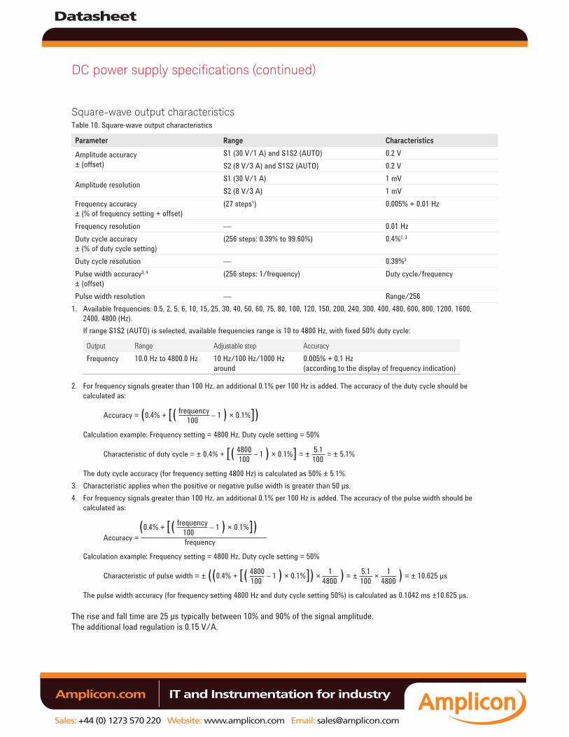
Square-wave output characteristicsTable 10. Square-wave output characteristics
Parameter Range Characteristics
Amplitude accuracy ± (offset)
S1 (30 V/1 A) and S1S2 (AUTO) 0.2 VS2 (8 V/3 A) and S1S2 (AUTO) 0.2 V
Amplitude resolutionS1 (30 V/1 A) 1 mVS2 (8 V/3 A) 1 mV
Frequency accuracy ± (% of frequency setting + offset)
(27 steps1) 0.005% + 0.01 Hz
Frequency resolution — 0.01 HzDuty cycle accuracy ± (% of duty cycle setting)
(256 steps: 0.39% to 99.60%) 0.4%2, 3
Duty cycle resolution — 0.39%3
Pulse width accuracy3, 4
± (offset)(256 steps: 1/frequency) Duty cycle/frequency
Pulse width resolution — Range/2561. Available frequencies: 0.5, 2, 5, 6, 10, 15, 25, 30, 40, 50, 60, 75, 80, 100, 120, 150, 200, 240, 300, 400, 480, 600, 800, 1200, 1600,
2400, 4800 (Hz).If range S1S2 (AUTO) is selected, available frequencies range is 10 to 4800 Hz, with fixed 50% duty cycle:
Output Range Adjustable step AccuracyFrequency 10.0 Hz to 4800.0 Hz 10 Hz/100 Hz/1000 Hz
around0.005% + 0.1 Hz(according to the display of frequency indication)
2. For frequency signals greater than 100 Hz, an additional 0.1% per 100 Hz is added. The accuracy of the duty cycle should be calculated as: Accuracy = (0.4% + [( frequency – 1 ) × 0.1%]) 100
Calculation example: Frequency setting = 4800 Hz, Duty cycle setting = 50% Characteristic of duty cycle = ± 0.4% + [( 4800 – 1 ) × 0.1%] = ± 5.1 = ± 5.1% 100 100
The duty cycle accuracy (for frequency setting 4800 Hz) is calculated as 50% ± 5.1%.3. Characteristic applies when the positive or negative pulse width is greater than 50 μs.4. For frequency signals greater than 100 Hz, an additional 0.1% per 100 Hz is added. The accuracy of the pulse width should be
calculated as: (0.4% + [( frequency – 1 ) × 0.1%]) 100 Accuracy = frequency
Calculation example: Frequency setting = 4800 Hz, Duty cycle setting = 50% Characteristic of pulse width = ± ((0.4% + [( 4800 – 1 ) × 0.1%]) × 1 ) = ± 5.1 × 1 ) = ± 10.625 µs 100 4800 100 4800
The pulse width accuracy (for frequency setting 4800 Hz and duty cycle setting 50%) is calculated as 0.1042 ms ±10.625 μs.
The rise and fall time are 25 μs typically between 10% and 90% of the signal amplitude.The additional load regulation is 0.15 V/A.
Datasheet
Sales: +44 (0) 1273 570 220 Website: www.amplicon.com Email: [email protected]
IT and Instrumentation for industry Amplicon.com
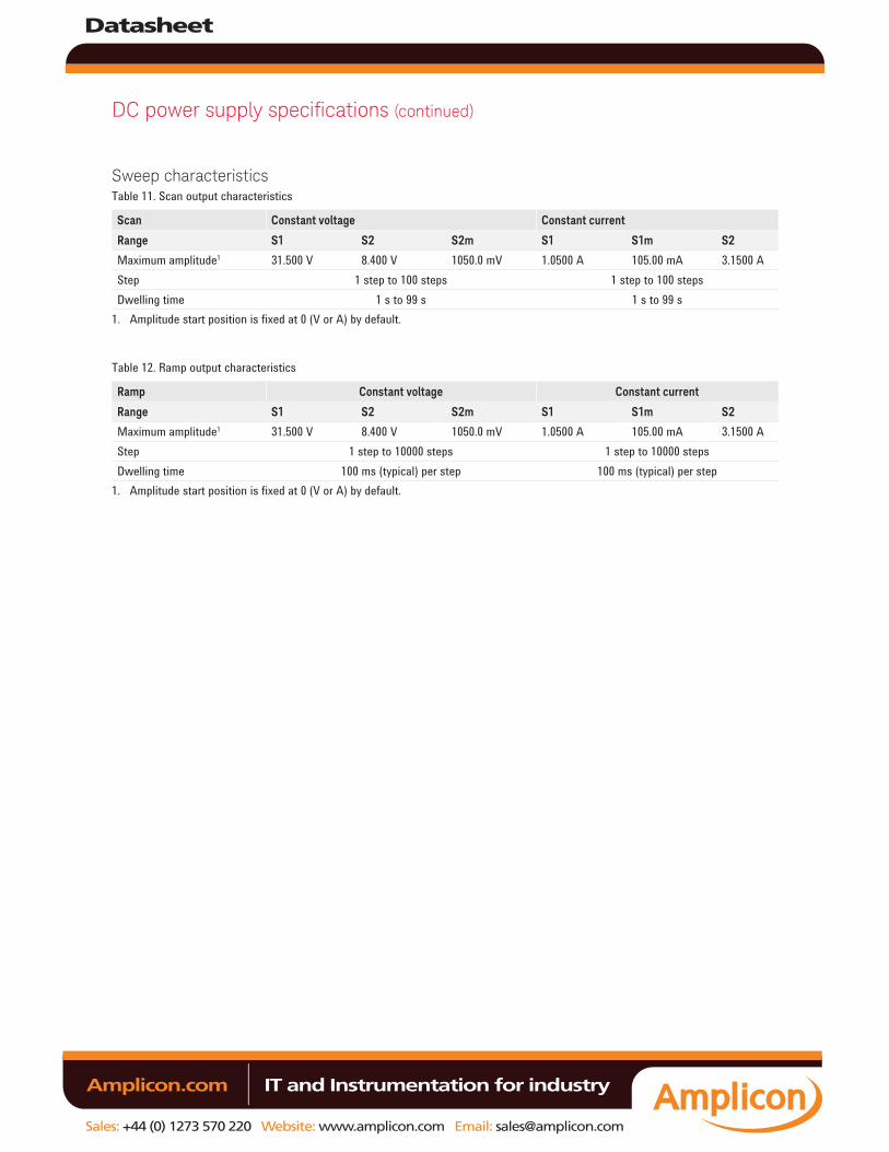
Sweep characteristicsTable 11. Scan output characteristics
Scan Constant voltage Constant current
Range S1 S2 S2m S1 S1m S2
Maximum amplitude1 31.500 V 8.400 V 1050.0 mV 1.0500 A 105.00 mA 3.1500 AStep 1 step to 100 steps 1 step to 100 stepsDwelling time 1 s to 99 s 1 s to 99 s
1. Amplitude start position is fixed at 0 (V or A) by default.
Table 12. Ramp output characteristics
Ramp Constant voltage Constant current
Range S1 S2 S2m S1 S1m S2
Maximum amplitude1 31.500 V 8.400 V 1050.0 mV 1.0500 A 105.00 mA 3.1500 AStep 1 step to 10000 steps 1 step to 10000 stepsDwelling time 100 ms (typical) per step 100 ms (typical) per step
1. Amplitude start position is fixed at 0 (V or A) by default.
DC power supply specifications (continued)
Datasheet
Sales: +44 (0) 1273 570 220 Website: www.amplicon.com Email: [email protected]
IT and Instrumentation for industry Amplicon.com
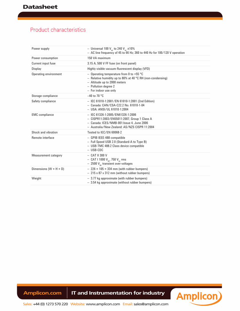
Product characteristics
Power supply – Universal 100 Vac to 240 Vac ±10%– AC line frequency of 45 to 66 Hz; 360 to 440 Hz for 100/120 V operation
Power consumption 150 VA maximumCurrent input fuse 3.15 A, 500 V FF fuse (on front panel)Display Highly visible vacuum-fluorescent display (VFD)Operating environment – Operating temperature from 0 to +55 °C
– Relative humidity up to 80% at 40 °C RH (non-condensing)– Altitude up to 2000 meters– Pollution degree 2– For indoor use only
Storage compliance –40 to 70 °CSafety compliance – IEC 61010-1:2001/EN 61010-1:2001 (2nd Edition)
– Canada: CAN/CSA-C22.2 No. 61010-1-04– USA: ANSI/UL 61010-1:2004
EMC compliance – IEC 61326-1:2005/EN61326-1:2006 – CISPR11:2003/EN55011:2007, Group 1 Class A – Canada: ICES/NMB-001:Issue 4, June 2006 – Australia/New Zealand: AS/NZS CISPR 11:2004
Shock and vibration Tested to IEC/EN 60068-2Remote interface – GPIB IEEE-488 compatible
– Full Speed USB 2.0 (Standard-A to Type B)– USB-TMC 488.2 Class device compatible– USB-CDC
Measurement category – CAT II 300 V– CAT I 1000 Vdc, 750 Vac rms– 2500 Vpk transient over-voltages
Dimensions (W × H × D) – 226 × 105 × 334 mm (with rubber bumpers)– 215 x 87 x 312 mm (without rubber bumpers)
Weight – 3.77 kg approximate (with rubber bumpers)– 3.54 kg approximate (without rubber bumpers)
Datasheet
Sales: +44 (0) 1273 570 220 Website: www.amplicon.com Email: [email protected]
IT and Instrumentation for industry Amplicon.com
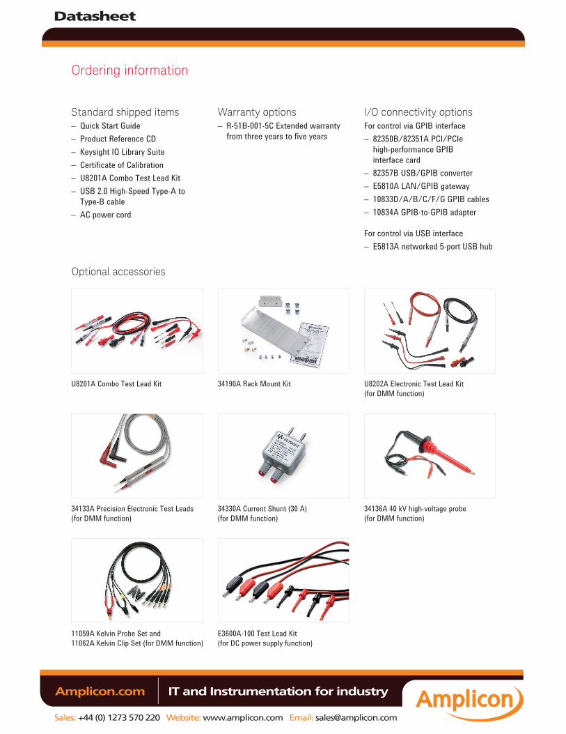
Ordering information
Standard shipped items– Quick Start Guide– Product Reference CD– Keysight IO Library Suite– Certificate of Calibration– U8201A Combo Test Lead Kit– USB 2.0 High-Speed Type-A to
Type-B cable– AC power cord
Warranty options– R-51B-001-5C Extended warranty
from three years to five years
U8201A Combo Test Lead Kit 34190A Rack Mount Kit U8202A Electronic Test Lead Kit(for DMM function)
34133A Precision Electronic Test Leads(for DMM function)
34330A Current Shunt (30 A)(for DMM function)
34136A 40 kV high-voltage probe(for DMM function)
11059A Kelvin Probe Set and 11062A Kelvin Clip Set (for DMM function)
E3600A-100 Test Lead Kit (for DC power supply function)
I/O connectivity optionsFor control via GPIB interface– 82350B/82351A PCI/PCIe
high-performance GPIB interface card
– 82357B USB/GPIB converter– E5810A LAN/GPIB gateway– 10833D/A/B/C/F/G GPIB cables– 10834A GPIB-to-GPIB adapter
For control via USB interface– E5813A networked 5-port USB hub
Optional accessories
Datasheet
Sales: +44 (0) 1273 570 220 Website: www.amplicon.com Email: [email protected]
IT and Instrumentation for industry Amplicon.com