data sheet part no.: l-c191wdt-hm3 light para
TRANSCRIPT

DATA SHEET
PART NO.: L-C191WDT-HM3
REV: A / 2
CUSTOMER’S APPROVAL : _______________ DCC : ____________
DRAWING NO. : DS-74-18-0018G DATE :2018-12-19 PAGE 1 of 13
PARA-FOR-065
PARA LIGHT

SURFACE MOUNT DEVICE LED
Part No. : L-C191WDT-HM3 REV: A / 2
� PACKAGE OUTLINE DIMENSIONS
Notes:
1. All dimensions are in millimeters.
2. Tolerance is ± 0.1mm (.004") unless otherwise noted.
� Features
� Top view, wide view angle, single color Chip LED.
� Package in 8mm tape on 7" diameter reels.
� Compatible with automatic Pick & Place equipment.
� Compatible with Infrared and Wave soldering reflow solder processes.
� EIA STD package.
� I.C. compatible.
� Pb free product.
� Meet RoHS Green Product.
DRAWING NO. : DS-74-18-0018G DATE :2018-12-19 PAGE 2 of 13
PARA-FOR-068
PARA LIGHT

SURFACE MOUNT DEVICE LED
Part No. : L-C191WDT-HM3 REV: A / 2
� CHIP MATERIALS
� Dice Material : InGaN
� Light Color : White
� Lens Color : Light Yellow Diffused.
� Absolute Maximum Ratings(Ta=25℃)
Symbol Parameter Rating Unit
PD Power Dissipation 76 mW
IPF Peak Forward Current
(1/10 Duty Cycle, 0.1ms Pulse Width) 80 mA
IF Continuous Forward Current 20 mA
- De-rating Linear From 25℃ 0.25 mA/℃
VR Reverse Voltage 5 V
ESD Electrostatic Discharge Threshold(HBM)Note A 1000 V
Topr Operating Temperature Range -40 ~ + 85 ℃
Tstg Storage Temperature Range -40 ~ + 85 ℃
Note A :
HBM : Human Body Model. Seller gives no other assurances regarding the ability of to
withstand ESD.
� Electro-Optical Characteristics(Ta=25℃)
Parameter Symbol Min. Typ. Max. Unit Test Condition
Luminous Intensity IV 120 140 mcd IF=5mA
Viewing Angle 2θ1/2 130 Deg Note 2
CIE Chromaticity X 0.269 IF=5mA
CIE Chromaticity Y 0.284
Forward Voltage VF 2.7 2.9 V IF =5mA
Reverse Current IR 50 μA VR = 5V
DRAWING NO. : DS-74-18-0018G DATE :2018-12-19 PAGE 3 of 13
PARA-FOR-068
PARA LIGHT

SURFACE MOUNT DEVICE LED
Part No. : L-C191WDT-HM3 REV: A / 2
Notes:
1. Luminous intensity is measured with a light sensor and filter combination that
proximities the CIE eye-response curve.
2. θ1/2 is the off-axis angle at which the luminous intensity is half the axial luminous
intensity.
3. Caution in ESD :
Static Electricity and surge damages the LED. It is recommended use a wrist band or
anti-electrostatic glove when handling the LED. All devices, equipment and machinery
must be properly grounded.
4. Major standard testing equipment by “Instrument System” Model : CAS140B Compact
Array Spectrometer and “KEITHLEY” Source Meter Model : 2400.
� Typical Electro-Optical Characteristics Curves
Fig.1 Relative Intensity vs. Wavelength
DRAWING NO. : DS-74-18-0018G DATE :2018-12-19 PAGE 4 of 13
PARA-FOR-068
PARA LIGHT
SURFACE MOUNT DEVICE LED
Part No. : L-C191WDT-HM3 REV: A / 2
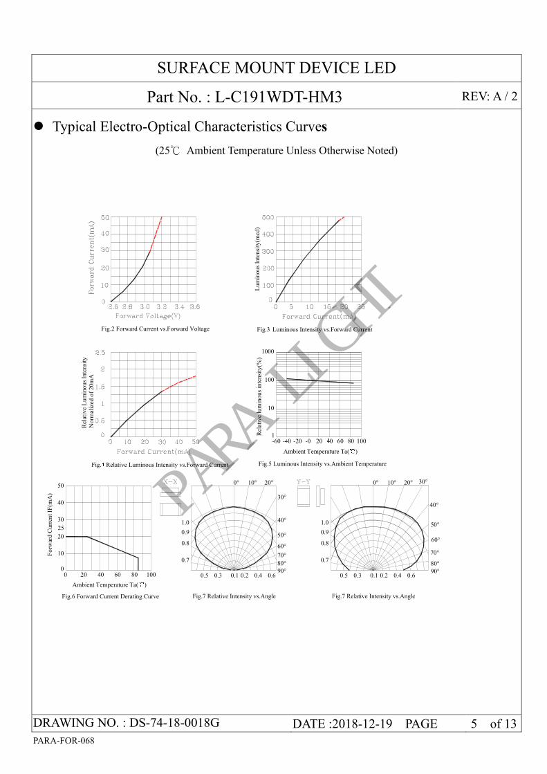
� Typical Electro-Optical Characteristics Curves
(25℃ Ambient Temperature Unless Otherwise Noted)
Rel
ativ
e lu
min
ous
inte
nsi
ty(%
)
Fig.5 Luminous Intensity vs.Ambient Temperature
Ambient Temperature Ta(℃)
20-40-601
-20 -0 40 60 10080
Fig.6 Forward Current Derating Curve
Ambient Temperature Ta(℃)
00
20 40 8060 100
Fig.3 Luminous Intensity vs.Forward Current
Lu
min
ous
lnte
nsi
ty(m
cd)
Fig.2 Forward Current vs.Forward Voltage
10
100
1000
Fo
rwar
d C
urr
ent
IF(m
A)
25
10
20
30
40
50
Fig.4 Relative Luminous Intensity vs.Forward Current
Rel
ativ
e L
um
ino
us
lnte
nsi
ty
Norm
aliz
ed o
f 2
0m
A
0.7
0.10.5 0.3 0.40.2 0.690°
80°
1.0
0.8
0.9
70°
60°
50°
40°
30°
0° 10° 20°
Fig.7 Relative Intensity vs.Angle
0.7
0.10.5 0.3 0.40.2 0.690°
80°
1.0
0.8
0.9
70°
60°
50°
40°
30°0° 10° 20°
Fig.7 Relative Intensity vs.Angle
DRAWING NO. : DS-74-18-0018G DATE :2018-12-19 PAGE 5 of 13
PARA-FOR-068
PARA LIGHT

SURFACE MOUNT DEVICE LED
Part No. : L-C191WDT-HM3 REV: A / 2
� Label Explanation
ITEM CODE:PARRA LIGHT
PART NO: L-C191WDT-HM3
IV --- Luminous Intensity Code
LOT NO: EM S L 12 09 0110
A---EM: Emos Code
B---S:SMD
L---Local
D---Year
E---Month
F---SPEC.
PACKING QUANTITY OF BAG :
3000pcs for 150、170、110、155、115 series
4000pcs for 191 series
5000pcs for 192 series
DATE CODE:2012 09 10
G H I
G--- Year
H--- Month
I --- Day
DRAWING NO. : DS-74-18-0018G DATE :2018-12-19 PAGE 6 of 13
PARA-FOR-068
A B C D E F
PARA LIGHT
SURFACE MOUNT DEVICE LED
Part No. : L-C191WDT-HM3 REV: A / 2
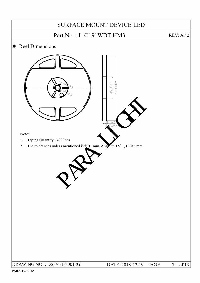
� Reel Dimensions
Notes:
1. Taping Quantity : 4000pcs
2. The tolerances unless mentioned is±0.1mm, Angle±0.5°, Unit : mm.
DRAWING NO. : DS-74-18-0018G DATE :2018-12-19 PAGE 7 of 13
PARA-FOR-068
PARA LIGHT

SURFACE MOUNT DEVICE LED
Part No. : L-C191WDT-HM3 REV: A / 2
� Package Dimensions Of Tape And Reel
Polarity
Progressive direction
Cathode
Notes: All dimensions are in millimeters.
Moisture Resistant Packaging
Notes : One reel in a bag, thirty-six bag in a carton. Unit : mm.
DRAWING NO. : DS-74-18-0018G DATE :2018-12-19 PAGE 8 of 13
PARA-FOR-068
Label
Aluminum moistue-proof bag Desiccant
Label
H:\
SM
D\S
MD
\SM
D°
ü×
°\±
ê?
?.j
pg
H:\
SM
D\S
MD
\SM
D°
ü×
°\±
ê?
?.j
pg
H:\
SM
D\S
MD
\SM
D°
ü×
°\±
ê?
?.j
pg
Reel
26
0
310
440
Carton
PARA LIGHT

SURFACE MOUNT DEVICE LED
Part No. : L-C191WDT-HM3 REV: A / 2
� Cleaning
� If cleaning is required , use the following solutions for less than 1 minute and less than 40℃.
� Appropriate chemicals: Ethyl alcohol and isopropyl alcohol.
� Effect of ultrasonic cleaning on the LED resin body differs depending on such factors as
the oscillator output, size of PCB and LED mounting method. The use of ultrasonic
cleaning should be enforced at proper output after confirming there is no problem.
� Suggest Soldering Pad Dimensions
Direction of PWB camber
and go to reflow furnace
Notes : Suggest stencil print screen thickness are 0.10mm maxNotes : Suggest stencil print screen thickness are 0.10mm maxNotes : Suggest stencil print screen thickness are 0.10mm maxNotes : Suggest stencil print screen thickness are 0.10mm maximum.imum.imum.imum.
DRAWING NO. : DS-74-18-0018G DATE :2018-12-19 PAGE 9 of 13
PARA-FOR-068
PARA LIGHT

SURFACE MOUNT DEVICE LED
Part No. : L-C191WDT-HM3 REV: A / 2
● Suggest Sn/Pb IR Reflow Soldering Profile Condition:
● Suggest Pb-Free IR Reflow Soldering Profile Condition:
DRAWING NO. : DS-74-18-0018G DATE :2018-12-19 PAGE 10 of 13
PARA-FOR-068
PARA LIGHT

SURFACE MOUNT DEVICE LED
Part No. : L-C191WDT-HM3 REV: A / 2
� Bin Code List
Luminous Intensity(IV), Unit:mcd@5mA Forward Voltage(VF), Unit:V@5mA
Bin Code Min Max Bin Code Min Max
R2 120 140 12 2.7 2.8
R3 140 160 13 2.8 2.9
Tolerance of each bin are±15% Tolerance of each bin are±0.1Volt
Color Rank (CIE chromaticity X , Y) @ 5mA
Rank A2 Rank A3
X 0.2554 0.2609 0.2694 0.2639 X 0.2609 0.2664 0.2749 0.2694
Y 0.272 0.282 0.282 0.272 Y 0.282 0.292 0.292 0.282
* Measurement of Color coordinates : +/- 0.02
DRAWING NO. : DS-74-18-0018G DATE :2018-12-19 PAGE 11 of 13
PARA-FOR-068
PARA LIGHT

PARA-FOR-068
SURFACE MOUNT DEVICE LED
Part No. : L-C191WDT-HM3 REV: A / 2
4. Lead-Free Soldering
For Reflow Soldering :
1、Pre-Heat Temp: 150-180℃,120sec.Max.
2、Soldering Temp: Temperature Of Soldering Pot Over 230℃,40sec.Max.
3、Peak Temperature: 260℃,5sec.
4、Reflow Repetition: 2 Times Max.
5、Suggest Solder Paste Formula : 93.3 Sn/3.1 Ag/3.1 Bi/0.5 Cu
For Soldering Iron (Not Recommended) :
1、Iron Tip Temp: 350℃ Max.
2、Soldering Iron: 30w Max.
3、Soldering Time: 3 Sec. Max. One Time.
For Dip Soldering :
1、Pre-Heat Temp: 150℃ Max. 120 Sec. Max.
2、Bath Temp: 265℃ Max.
3、Dip Time: 5 Sec. Max.
5. Drive Method
Circuit model A Circuit model B
(A)Recommended circuit.
(B)The difference of brightness between LED`s could be found due to the Vf-If characteristics of LED.
DRAWING NO. : DS-74-18-0018G DATE :2018-12-19 PAGE 12 of 13
PARA LIGHT

PARA-FOR-068
SURFACE MOUNT DEVICE LED
Part No. : L-C191WDT-HM3 REV: A / 2
6.Reliability Test
Classification Test Item Test Condition Reference Standard
Endurance Test
Operation Life
Ta= Under Room Temperature As Per Data
Sheet Maximum Rating
*Test Time= 1000HRS
(-24HRS,+72HRS)*@5mA.
MIL-STD-750D:1026 (1995)
MIL-STD-883D:1005 (1991)
JIS C 7021:B-1 (1982)
High Temperature
High Humidity
Storage
IR-Reflow In-Board, 2 Times
Ta= 65±5℃,RH= 90~95%
*Test Time= 1000HRS±2HRS
MIL-STD-202F:103B(1980)
JIS C 7021:B-11(1982)
High Temperature
Storage
Ta= 105±5℃
Test Time= 1000HRS (-24HRS,72HRS)
MIL-STD-883D:1008 (1991)
JIS C 7021:B-10 (1982)
Low Temperature
Storage
Ta= -55±5℃
*Test Time=1000HRS (-24HRS,72H RS) JIS C 7021:B-12 (1982)
Environmental
Test
Temperature
Cycling
105±5℃ -55±5℃
10mins 10mins 100 Cycles
MIL-STD-202F:107D (1980)
MIL-STD-750D:1051(1995)
MIL-STD-883D:1010 (1991)
JIS C 7021:A-4(1982)
Thermal
Shock
IR-Reflow In-Board, 2 Times
105±5℃ -55℃±5℃
10mins 10mins 100 Cycles
MIL-STD-202F:107D(1980)
MIL-STD-750D:1051(1995)
MIL-STD-883D:1011 (1991)
Solder
Resistance
Tsol= 260 ± 5℃
Dwell Time= 10 ± 1sec
MIL-STD-202F:210A(1980)
MIL-STD-750D:2031(1995)
JIS C 7021:A-1(1982)
Solder ability
Tsol= 235 ± 5℃
Immersion time 2±0.5 sec
Immersion rate 25±2.5 mm/sec
Coverage ≧95% of the dipped surface
MIL-STD-202F:208D(1980)
MIL-STD-750D:2026(1995)
MIL-STD-883D:2003(1991)
IEC 68 Part 2-20
JIS C 7021:A-2(1982)
7.Others:
The appearance and specifications of the product may be modified for improvement without notice.
DRAWING NO. : DS-74-18-0018G DATE :2018-12-19 PAGE 13 of 13
PARA-FOR-068
PARA LIGHT