data sheet fhv regulating valve temperature control of...
TRANSCRIPT
VD.UI.C4.02ProducedbyDanfossA/S©01/2007 1
Data sheet FHV regulating valve Temperature control of individual floor heated rooms or mixed floor heating/radiator systems
Application
Ordering and technical data
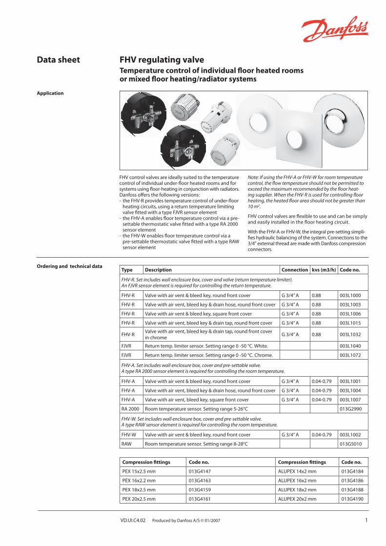
FHVcontrolvalvesareideallysuitedtothetemperaturecontrolofindividualunder-floorheatedroomsandforsystemsusingfloor-heatinginconjunctionwithradiators.Danfossoffersthefollowingversions:-theFHV-Rprovidestemperaturecontrolofunder-floor heatingcircuits,usingareturntemperaturelimiting valvefittedwithatypeFJVRsensorelement-theFHV-Aenablesfloortemperaturecontrolviaapre- settablethermostaticvalvefittedwithatypeRA2000 sensorelement-theFHV-Wenablesfloortemperaturecontrolviaa pre-settablethermostaticvalvefittedwithatypeRAW sensorelement
Note: If using the FHV-A or FHV-W for room temperature control, the flow temperature should not be permitted to exceed the maximum recommended by the floor heat-ing supplier. When the FHV-R is used for controlling floor heating, the heated floor area should not be greater than 10 m2.
FHVcontrolvalvesareflexibletouseandcanbesimplyandeasilyinstalledinthefloorheatingcircuit.
WiththeFHV-AorFHV-W,theintegralpre-settingsimpli-fieshydraulicbalancingofthesystem.Connectionstothe3/4"externalthreadaremadewithDanfosscompressionconnectors.
Type Description Connection kvs (m3/h) Code no.
FHV-R. Set includes wall enclosure box, cover and valve (return temperature limiter). An FJVR sensor element is required for controlling the return temperature.
FHV-R Valvewithairvent&bleedkey,roundfrontcover G3/4”A 0.88 003L1000
FHV-R Valvewithairvent,bleedkey&drainhose,roundfrontcover G3/4”A 0.88 003L1003
FHV-R Valvewithairvent&bleedkey,squarefrontcover G3/4”A 0.88 003L1006
FHV-R Valvewithairvent,bleedkey&draintap,roundfrontcover G3/4”A 0.88 003L1015
FHV-R Valvewithairvent,bleedkey&draintap,roundfrontcoverinchrome G3/4”A 0.88 003L1032
FJVR Returntemp.limitersensor.Settingrange0-50°C.White. 003L1040
FJVR Returntemp.limitersensor.Settingrange0-50°C.Chrome. 003L1072
FHV-A. Set includes wall enclosure box, cover and pre-settable valve. A type RA 2000 sensor element is required for controlling the room temperature.
FHV-A Valvewithairvent&bleedkey,roundfrontcover G3/4”A 0.04-0.79 003L1001
FHV-A Valvewithairvent,bleedkey&drainhose,roundfrontcover G3/4”A 0.04-0.79 003L1004
FHV-A Valvewithairvent,bleedkey,squarefrontcover G3/4”A 0.04-0.79 003L1007
RA2000 Roomtemperaturesensor.Settingrange5-26°C 013G2990
FHV-W. Set includes wall enclosure box, cover and pre-settable valve. A type RAW sensor element is required for controlling the room temperature.
FHV-W Valvewithairvent&bleedkey,roundfrontcover G3/4”A 0.04-0.79 003L1002
RAW Roomtemperaturesensor.Settingrange8-28°C 013G5010
Compression fittings Code no. Compression fittings Code no.
PEX15x2.5mm 013G4147 ALUPEX14x2mm 013G4184
PEX16x2.2mm 013G4163 ALUPEX16x2mm 013G4186
PEX18x2.5mm 013G4159 ALUPEX18x2mm 013G4188
PEX20x2.5mm 013G4161 ALUPEX20x2mm 013G4190
2 VD.UI.C4.02ProducedbyDanfossA/S©01/2007
Data sheet Regulating Valve, type FHV
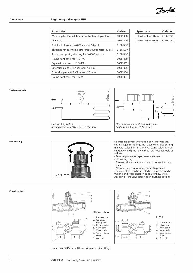
Pre-setting Danfosspre-settablevalvebodiesincorporateeasysettingadjustmentringswithclearlyengravedsettingmarkersscaledfrom1-7andN.Settingvaluescanbesetquicklyandprecisely,withouttheneedfortools,asfollows:-Removeprotectivecaporsensorelement-Liftsettingring-Turnanti-clockwisetothedesiredengravedsetting
value-AllowsettingringtospringbackintopositionThepresetlevelcanbeselectedin0.5incrementsbe-tween1and7(seechartonpage3forflowrates).AtsettingNthevalveisfullyopen(flushingoption).
Construction
Connection:3/4"externalthreadforcompressionfittings.
Spare parts Code no.
GlandsealforFHV-A 013G0290
GlandsealforFHV-R 013G0290
Accessories Code no.
Mountingtool/installationaidwithintegralspiritlevel 003L1338
Drainkey 003L1340
AntitheftplugsforRA2000sensors(50pcs) 013G1232
ThreadedrangelimitingpinsforRA2000sensors(30pcs) 013G1237
Toolkit,comprisingallenkeyforRA2000sensors 013G1236
RoundfrontcoverforFHV-R/A 003L1050
SquarefrontcoverforFHV-R/A 003L1052
ExtensionpieceforRAsensors17,9mm 003L1035
ExtensionpieceforFJVRsensors17,9mm 003L1036
RoundfrontcoverforFHV-W 003L1051
Floor heating system; heating circuit with FHV-A or FHV-W in flow
Floor temperature control, mixed system; heating circuit with FHV-R in return
Systemlayouts
FHV-A/FHV-W
1. Pressurepin2. Glandseal3. O-ringseal4. Returnspring5.Valvecone6. Valvebody7. Connections, G¾A8. Airvent
7
8
2
5 6
FHV-R
1. Pressurepin2. Glandseal3. Valvecone4. Valvebody5.Connections, G¾A6. Airvent
FHV-A/FHV-W
VD.UI.C4.02ProducedbyDanfossA/S©01/2007 3
Data sheet Regulating Valve, type FHV
Materialsincontactwithwater
Settingcylinder PPS
Spindle Ms,resistantagainstde-zincification
O-ring EPDM
Valvecone NBR
Pressurepin,valvespring Chrome-platedsteel
Valvebody,othermetalparts Ms58
Operationconditions
Max.operatingpressure 6bar
Max.differentialpressure 0,6bar
Testpressure 10bar
Max.flowtemperature 90°C
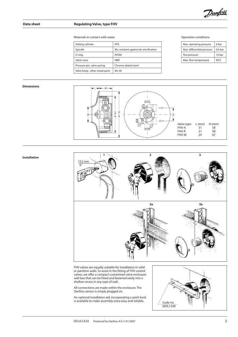
Dimensions
Valvetype L(mm) D(mm)FHV-A 31 58FHV-R 31 58FHV-W 24 67
Installation
FHVvalvesareequallysuitableforinstallationinsolidorpartitionwalls.ToassistinthefittingofFHVcontrolvalves,weofferacompactcustomisedvalveenclosurewallboxthatcanbefittedandfastenedeasilyintoashallowrecessinanytypeofwall.
Allconnectionsaremadewithintheenclosure.TheDanfosssensorissimplypluggedon.
Anoptionalinstallationaid,incorporatingaspiritlevel,isavailabletomakeassemblyextraeasyandreliable.
152mm6"
Codeno.003L1338
1 2 3
2a 3a
4 VD.UI.C4.02ProducedbyDanfossA/S©01/2007
Data sheet Regulating Valve, type FHV
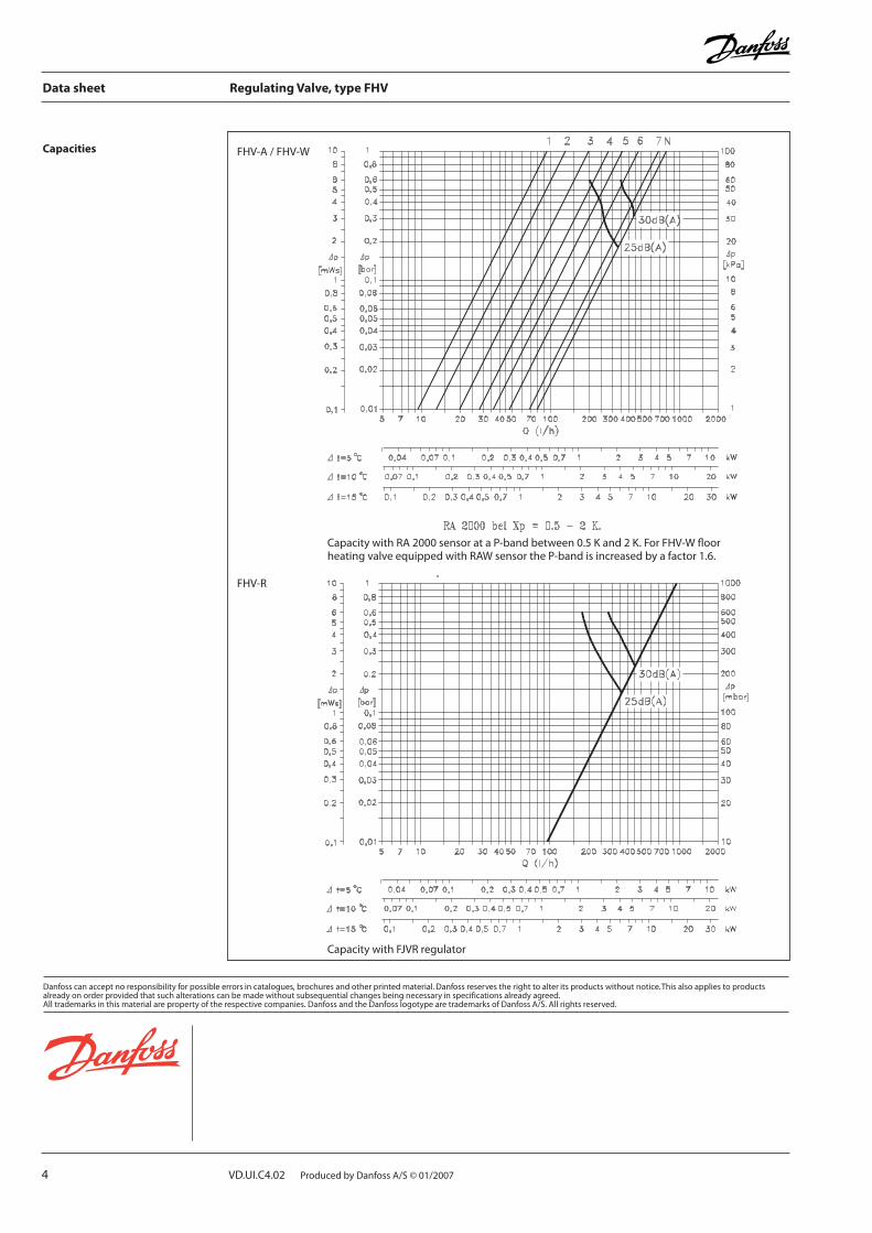
Capacities
CapacitywithRA2000sensorataP-bandbetween0.5Kand2K.ForFHV-WfloorheatingvalveequippedwithRAWsensortheP-bandisincreasedbyafactor1.6.
CapacitywithFJVRregulator
FHV-A/FHV-W
FHV-R