data exchange & collaboration between ptc creo® and mentor
TRANSCRIPT

PTC.comPage 1 of 10 | Data Exchange & Collaboration between PTC Creo and Mentor Graphics Xpedition
Current electro-mechanical designs have many challenges that can significantly increase design effort and the time-to-market.
Typically, these challenges are separated into two groups:
• Collision and Connectivity design challenges
• Synchronization issues
These obstacles increase in difficulty when the requirements are not correctly communicated between collaborating team members.
Component and mechanical clearances must be accounted for in both the electrical and mechanical designs in order to ensure that no physical violations occur when the PCB is placed within the enclosure and/or entire system. Tight synchronization between the electrical and mechanical flows is required to ensure that both designs are correctly aligned for fabrication.
Modern designs require functionality that spans mul-tiple design disciplines. This requires close communi-cation between electrical and mechanical engineers from each team. Designers are no longer bound by a single domain. Many products result from collabora-tion with teams that work across multiple countries and continents, which presents a challenge when communicating between the different designers and engineers in an electro-mechanical system.
Data Exchange & Collaboration between PTC Creo® and Mentor Graphics® Xpedition– Linda Mazzitelli, Principal Technical Account Specialist, PTC
Alex Grange, Technical Marketing Engineer, Mentor Graphics Corp.
Today, many companies still utilize Intermediate Data Format (IDF) to transfer information between electri-cal and mechanical systems. This process is typically a static file transfer of the entire design database and while it does work, it is extremely difficult to know what changed and where just by looking at the imported file As a result, it is necessary to provide written docu-mentation along with marked up PDF’s or PPT’s to ensure the changes are clearly communicated and that nothing is lost during this process. Missing or missed design information can result in loss of time and rev-enue due to multiple re-spins of the same project, sim-ply because the correct information was not applied or understood during the exchange process.
With the introduction of the ProSTEP iViP Incremental Data Exchange (IDX) communication protocol, design-ers are now able to fully synchronize their data between both ECAD and MCAD and more effectively collaborate on critical design items between domains ensuring that the design intent is interpreted correctly. This allows designers to collaborate and identify issues much more easily throughout the design process, which in turns enables more robust designs that get out to market faster.

PTC.comPage 2 of 10 | Data Exchange & Collaboration between PTC Creo and Mentor Graphics Xpedition
The following shows the methodology of communi-cating within electro-mechanical designs and dem-onstrates the clear advantages of adopting the new ProSTEP exchange protocol.
Design Flow
Defining a design flow is critical in enabling an efficient process. The time invested in this stage reduces redundant steps and ensures that correct data is exchanged and enforced throughout the project.
Figure 1 – ProSTEP ECAD/MCAD Collaboration
In most electro-mechanical projects, critical design constraints are first defined by the mechanical engi-neer, including board outline, mounting hole loca-tions, placement/routing keep-out areas, connector placement etc. The design requirements and board elements are then exchanged with the ECAD designer to ensure that the correct information is used to start the project. This initial exchange would be the ‘Baseline’ file and is the same as if you were using IDF – as it will contain the entire assembly database from the mechanical domain. However, that is the only similarity between the two. The new ProSTEP iViP schema now allows you to go beyond sending a single, static file to/from the each design team by allowing each domain to send incremental data ie: only what changed, after the initial Baseline exchange. This facilitates a much more consistent and accurate flow of information back and forth between design dis-ciplines as it also provides a report of the differences, a way to include notes about what changed directly in the IDX file itself, and the ability to graphically interro-gate the updates on the PCB or mechanical assembly and ‘Accept’ or ‘Reject’ them. This fosters closer col-laboration and enables early identification of critical issues during the design flow.
The following steps outline a typical workflow between ECAD and MCAD design tools using the ProSTEP iViP Schema:
• The mechanical engineer creates a PCB inside an assembly that mounts to existing hardware
- Mounting holes are created, Keepins/Keepouts are defined, and board outline.
• A ‘Baseline’ IDX file is exported to the ECAD designer
• The Baseline is accepted in the ECAD design, synchronizing the ECAD with the MCAD databases
ProSTEP Collaboration

PTC.comPage 3 of 10 | Data Exchange & Collaboration between PTC Creo and Mentor Graphics Xpedition
• The board is modified in either the MCAD or ECAD tool suite and sent to the respective tool using a proposal (Incremental) collaboration file
- Typically at this stage, the PCB designer will begin placing critical components on the board or will finish the placement and will send back over to MCAD for review
• The ECAD designer (or MCAD engineer) then reviews the updates and either Accepts or Rejects the proposal and sends a response file back to the originator
- Note: In the case of multiple change proposals in one IDX file, items can be accepted/rejected individually by the receiving domain
• The second designer/engineer accepts the ‘Response’ file and the process continues
- Note: ‘Response’ files allow each side to verify that the IDX file was received and reviewed. It also re-syncs the collaboration state between the two domains
Independent Collaboration with the ProSTEP Protocol
To date, the Intermediate Data Format (IDF) has been widely-used to exchange PCB data between mechani-cal and electrical designs. IDF was initially devel-oped and released in 1992 by Mentor Graphics as a non-proprietary data format for exchanging ECAD and MCAD design data and was quickly adopted as an unofficial ‘industry standard’. IDF requires that the entire database be passed back-and-forth each time without a way to easily see what changers were being proposed. As a result, collaboration between electri-cal and mechanical domains is infrequent ie: typically at the beginning and end, causing information gaps throughout the design process. The gaps in informa-tion in the IDF cause many instances of product failure due to an incomplete picture of the design intent from the perspectives of the electrical and mechanical design teams.
With Mentor Graphics’ leadership, the ProSTEP iViP ECAD/MCAD Project Group developed an open stan-dard in May 2010 that allows any ECAD and MCAD vendor to address today’s electromechanical col-laboration design challenges. PTC participated in the ProSTEP Project group and is the first mechanical vendor to support Mentor Graphics’ EDMD initiative.
The ProSTEP protocol was developed as an indepen-dent format that allows both ECAD and MCAD suites to communicate in the same language, but interpret their own items natively in their tool. This allows designers to collaborate within their own environments, saving on training and ramp-up time that would otherwise be needed to learn a new tool. Communication between the electrical and mechanical designers can now occur at any time or frequency as a result of the simplified exchange process ie: sending over only the items that have changed vs. the entire database therefore ensur-ing design consistency and detection of violations early in the design process.
Figure 2 – Process flow of ECAD MCAD Collaboration

PTC.comPage 4 of 10 | Data Exchange & Collaboration between PTC Creo and Mentor Graphics Xpedition
To manage today’s design challenges and beyond, the ProSTEP iViP format is continuously updated to ensure that the integrity of the design data and the data exchange requirements are handled in both ECAD and MCAD domains. The ProSTEP schema is consis-tently undergoing further enhancements to improve model management and additional collaboration fea-tures to ensure that both the electrical and mechani-cal designer can highlight issues immediately and fix violations before they go to production.
Xpedition xPCB Layout 3D
With the VX release, Mentor Graphics incorporated a complete, photorealistic 3D environment for visualiza-tion within physical layouts. Viewing the ECAD design in a full 3D environment allows you to get a second set of eyes on the design, immediately identify critical areas and resolve electro-mechanical problems early to eliminate costly, last-minute redesigns.
Figure 3 – Flow diagram of ProSTEP data exchange
Figure 4 – 3D Planning Groups in Xpedition xPCB Layout
ProSTEP Data Exchange
Xpedition xPCB Layout
Collaboration
3DModeler
Collaboration
3DModeler
PTC Creo Parametric
Providing a good, 3D representation of the design on the ECAD side also allows you to develop a good placement strategy up front and maximize board real estate while reducing layer count. In many cases, the electrical designer cannot validate the component placement strategy until the design is fully realized in 3D. With Mentor Graphics’ new 3D implementation, designers can immediately validate their PCB to iden-tify over and under constrained areas in the design, therefore optimizing real estate and reducing poten-tial electrical and thermal issues. With the new 3D environment, designers can use 3D placement groups to investigate different placement strategies. This allows the quick identification of minimum X, Y and Z real estate required when all components are placed.
Designers often want to investigate internal layers to identify non-functional padstack and internal plane layers. With the 3D viewer, you are able to identify cop-per regions that could potentially cause high thermal densities that result in poor design performance. With Xpedition, you can scale the thickness of the board and provide cuts in the X, Y and Z direction to immediately highlight potential design issues:

PTC.comPage 5 of 10 | Data Exchange & Collaboration between PTC Creo and Mentor Graphics Xpedition
The 3D view in Xpedition is not just an interpretation of the 2D information, but a true photorealistic view of how the design will be fabricated. Xpedition provides complete view controls, including transparency, for board elements such as traces, components, silkscreen, solder mask, and vias. This allows you to resolve issues that are difficult to identify in the design process without the full design rule checks from manufacturing.
Figure 5 – Display of internal layers in 2D (top) and 3D (bottom)
Figure 6 – Visualization of traces (1st), silkscreen and solder mask (2nd), copper information (3rd) and internal layers (4th) in Xpedition xPCB Layout

PTC.comPage 6 of 10 | Data Exchange & Collaboration between PTC Creo and Mentor Graphics Xpedition
Example: 5th 10th<ERROR =>OPTIMAL=>MINIMUM<
BF
A BOPTIMAL
OPTIMAL
MINIMUM
MINIMUM
ERROR
ERROR
You can start creating designs immediately using our comprehensive 3D model library. There are currently over 4 million parts available and thousands are added each quarter. With the 3D library, you have access to an immense amount of parametric information to help start designs and run vibration analyses. The 3D library that Mentor Graphics provides does not just contain physical representations, but also parametric information that assists in the alignment and analy-sis of the components. For example, every model in the library has the physical and material properties to identify the mass and assist vibrational studies to before physical simulation.
Figure 7 – Example models from Mentors 3D library with over 4 million parts
Figure 8 – Identify collisions in real time (top) and identification of optimal, minimum and violation rules (bottom) in Xpedition
Xpedition uses a true parametric 3D mechanical kernel, with 3D constraints, dynamic collision detection, and batch verification. Designers can define their minimum and optimal design clearances and identify in real-time design violations using the built-in clearances created in Xpedition.
Mechanical components, such as the chassis or heat sinks can be easily added and validated in the electri-cal environment. Xpedition supports true multi-board capability, allowing users to import sub-assemblies from other PCB designs to visualize the entire system in a single environment. Using the functionality within the 3D viewer improves the integration of mechanical design data and allows quick collaboration between the electrical and mechanical design process.

PTC.comPage 7 of 10 | Data Exchange & Collaboration between PTC Creo and Mentor Graphics Xpedition
Figure 10 – Preview the proposed changes using ECAD Compare
Figure 9 – Manufactured board (top) and 3D visualization in Xpedition (bottom)
PTC Creo ECAD-MCAD Collaboration Extension (ECX)
Together with the Mentor 3D functionality, PTC Creo ECX provides you a fully integrated package that offers interaction with the ECAD view, fostering tighter ECAD MCAD design collaboration. By leveraging the capa-bilities in PTC Creo Parametric ECAD-MCAD Collabo-ration Extension, you can collaborate more efficiently by electronically proposing, identifying, managing and capturing the history of changes across mechanical and electrical disciplines.
PTC Creo View ECAD Validate provides a ‘smart’ report-style interface that enables the MCAD engineer to quickly and easily view the incremental updates, review any notes provided from the PCB designer and then graphically highlight the before-and-after condi-tion of the proposed changes. From there, they can then choose to ‘Accept’ or ‘Reject’ the updates and send a ‘Response’ file back to ECAD with embedded notes to electronically communicate feedback, eliminating the need for additional emails, PDF and/or PPT mark-ups.
PTC Creo View ECAD Compare provides an environ-ment for comparing design differences and immedi-ately identifying the impact of design update propos-als using the same IDX file functionality previously described in the ECAD-MCAD Collaboration process. The designer or engineer will have the ability to view the original and changed states of a proposal, then accept or reject each item and electronically commu-nicate that feedback to the originator. Compare can be used for not only seeing differences between ECAD and MCAD, but also from layout-to-layout, schematic-to-schematic artwork-to-artwork etc.
Once the design is underway or complete, PTC Creo View ECAD Suite provides powerful functionality, including the ability to load multiple design views into a single, easy-to-use GUI. It enables cross highlight-ing between Mentor Schematic, PCB and PTC Creo Parametric MCAD abstractions without having to learn another design tool to do that. This provides a way to not only for collaboration between MCAD and ECAD design authors, but even extended team members will be able to browse and validate the quality of the design including querying nets and components, measuring distances and minimum gaps, highlighting and isolat-ing specific net and component data, all from within the PTC Creo View ECAD Suite environment. You will also be able to electronically communicate changes, ideas, or redline markups back to other users, using the bookmarked views of your markups. PTC Creo View ECAD provides is the next-generation of truly heterogeneous visual collaboration environment for both ECAD & MCAD.
Before change
After change

PTC.comPage 8 of 10 | Data Exchange & Collaboration between PTC Creo and Mentor Graphics Xpedition
Design Domain
Create additional incremental changes
Create Baseline Send Proposed Changes Accept/Reject Proposal Send Response
Propose Changes Inform ChangesSynchronize Data Modify Design
The next phase of Electro-mechanical communication
In earlier standards for electro-mechanical communi-cation, data was exchanged in one direction and would typically be transferred once in the design process. Lack of collaboration such as this causes issues to crop up late in the design process. This in turn causes significant re-work and additional time to complete the project under the correct specifications.
With the new ProSTEP communication protocol, collaboration between the electrical and mechani-cal domains is encouraged and incremental changes to the specification are easy to share as the design progresses. To collaborate between ECAD and MCAD domains, users have access to all relevant informa-tion in the other domain. This improved, two-way flow of information avoids potential issues and accelerates project development.
Figure 11 – PTC Creo View
Figure 12 – Flow Diagram of Collaboration between Xpedition and PTC Creo
To collaborate on only modified items, a baseline can be exported from either electrical or mechanical domains and applied to the corresponding tool. This synchronizes both domains with the same data set. This benefits users so that only the modified objects are seen and collaborated with, rather than the whole data model. Once the data model has been synchro-nized, either the mechanical or electrical domains can create incremental changes and propose them to the corresponding designer. The designer can then ‘Accept’ or ‘Reject’ the proposed changes and send the original owner a response to pass on the true design intent. This indicates the feedback exchanged between the two domains. Once the response has been accepted, the collaboration process can start again with another incremental change, until the design is complete.
PTC.comPage 9 of 10 | Data Exchange & Collaboration between PTC Creo and Mentor Graphics Xpedition
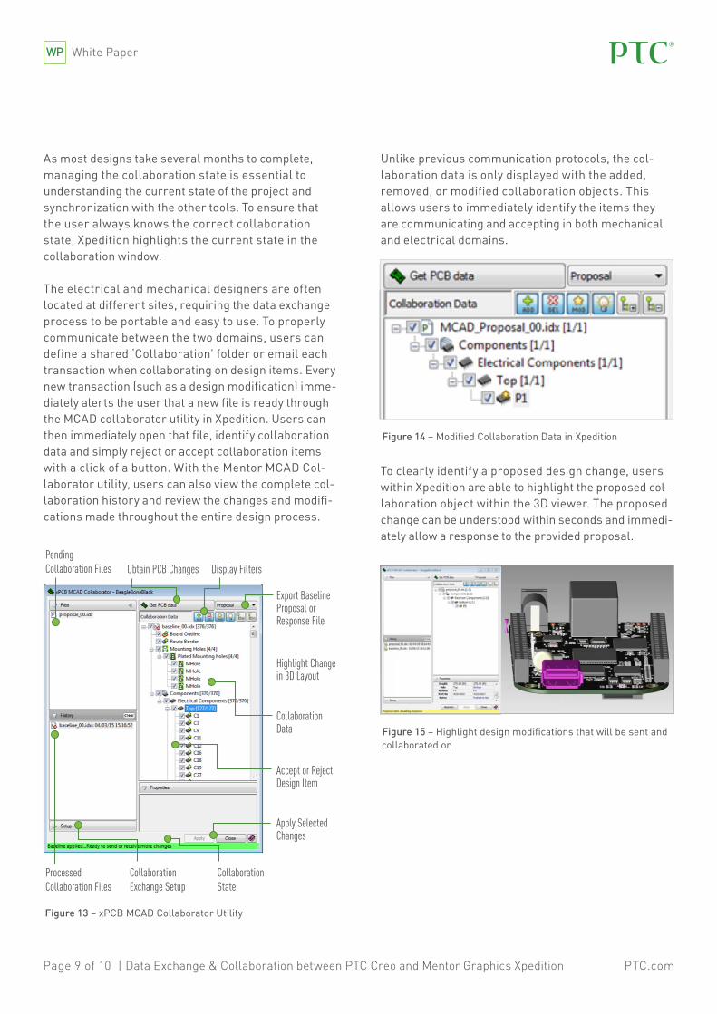
As most designs take several months to complete, managing the collaboration state is essential to understanding the current state of the project and synchronization with the other tools. To ensure that the user always knows the correct collaboration state, Xpedition highlights the current state in the collaboration window.
The electrical and mechanical designers are often located at different sites, requiring the data exchange process to be portable and easy to use. To properly communicate between the two domains, users can define a shared ‘Collaboration’ folder or email each transaction when collaborating on design items. Every new transaction (such as a design modification) imme-diately alerts the user that a new file is ready through the MCAD collaborator utility in Xpedition. Users can then immediately open that file, identify collaboration data and simply reject or accept collaboration items with a click of a button. With the Mentor MCAD Col-laborator utility, users can also view the complete col-laboration history and review the changes and modifi-cations made throughout the entire design process.
Figure 13 – xPCB MCAD Collaborator Utility
Figure 14 – Modified Collaboration Data in Xpedition
Figure 15 – Highlight design modifications that will be sent and collaborated on
Unlike previous communication protocols, the col-laboration data is only displayed with the added, removed, or modified collaboration objects. This allows users to immediately identify the items they are communicating and accepting in both mechanical and electrical domains.
To clearly identify a proposed design change, users within Xpedition are able to highlight the proposed col-laboration object within the 3D viewer. The proposed change can be understood within seconds and immedi-ately allow a response to the provided proposal.
Obtain PCB ChangesPending Collaboration Files
ProcessedCollaboration Files
Collaboration Exchange Setup
Collaboration State
Display Filters
Export Baseline Proposal or Response File
Highlight Change in 3D Layout
CollaborationData
Accept or RejectDesign Item
Apply Selected Changes

PTC.comPage 10 of 10 | Data Exchange & Collaboration between PTC Creo and Mentor Graphics Xpedition
The exact parameters of each modified object are high-lighted, allowing users to identify new changes to all design objects from location, reference designator, pad-stack, height and many more user defined properties.
In the old collaboration protocol, users relied on paper and verbal exchanges. With the new collaboration methodology, users can define collaboration notes on each object. This allows the full design intent to be managed and passed from both mechanical and electrical domains.
With MCAD collaboration, users are given a platform for collaborative discussions, ensuring that the correct design intent is interpreted and the design requirements are met.
Conclusion
There are numerous design challenges in electro-mechanical systems that can cause issues that affect both the electrical and mechanical domains. The ProSTEP scheme addresses these electromechanical issues to ensure that both domains are synchronized to enable consistent, iterative communication between design disciplines. This robust scheme keeps design teams synchronized and avoids rework late in the design flow. The MCAD collaboration implementation enables ECAD and MCAD teams to optimize design placement and electrical requirements within tight form factor constraints, while still meeting quality, reliability, and performance requirements. ProSTEP increases productivity as fewer electromechanical re-spins allows more time for new projects.
The easy-to-use interface in ProSTEP enables quick design change proposals, rejections, acceptances, and handles the final agreements and synchronization. ProSTEP optimizes designer efficiency, which in turn enables product constraints and performance to be met with less time and less development costs.
© 2016, PTC Inc. All rights reserved. Information described herein is furnished for informational use only, is subject to change without notice, and should not be taken as a guarantee, commitment, condition or offer by PTC. PTC, the PTC logo, Product & Service Advantage, Creo, Elements/Direct, Windchill, Mathcad, Arbortext, PTC Integrity, Servigistics, ThingWorx, ProductCloud and all other PTC product names and logos are trademarks or registered trademarks of PTC and/or its subsidiaries in the United States and other countries. All other product or company names are property of their respective owners.
©Copyright Mentor Graphics Corporation 2015. All rights reserved.
This document contains information that is proprietary to Mentor Graphics® Corporation. The original recipient of this document may duplicate this document in whole or in part for internal business purposes only, provided that this entire notice appears in all copies. In duplicating any part of this document, the recipi-ent agrees to make every reasonable effort to prevent the unauthorized use and distribution of the proprietary information.
Trademarks that appear in Mentor Graphics product publications that are not owned by Mentor Graphics are trademarks of their respective owners.
J5975–Mentor–Joint–EN–0116
In partnership with