data center fabric evolution - cisco...data-plane vs. control-plane loop control - vpc peers can...
TRANSCRIPT
Cisco Public © 2011 Cisco and/or its affiliates. All rights reserved. 1
Tomáš Michaeli
Oct-2012
Data Center Fabric Evolution
© 2011 Cisco and/or its affiliates. All rights reserved. Cisco Public 2
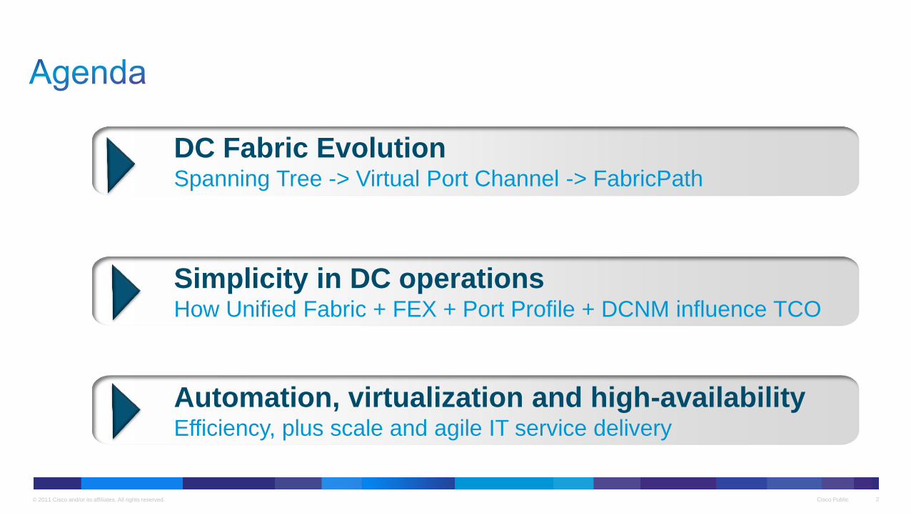
DC Fabric Evolution Spanning Tree -> Virtual Port Channel -> FabricPath
Simplicity in DC operations How Unified Fabric + FEX + Port Profile + DCNM influence TCO
Automation, virtualization and high-availability Efficiency, plus scale and agile IT service delivery
© 2011 Cisco and/or its affiliates. All rights reserved. Cisco Public 3
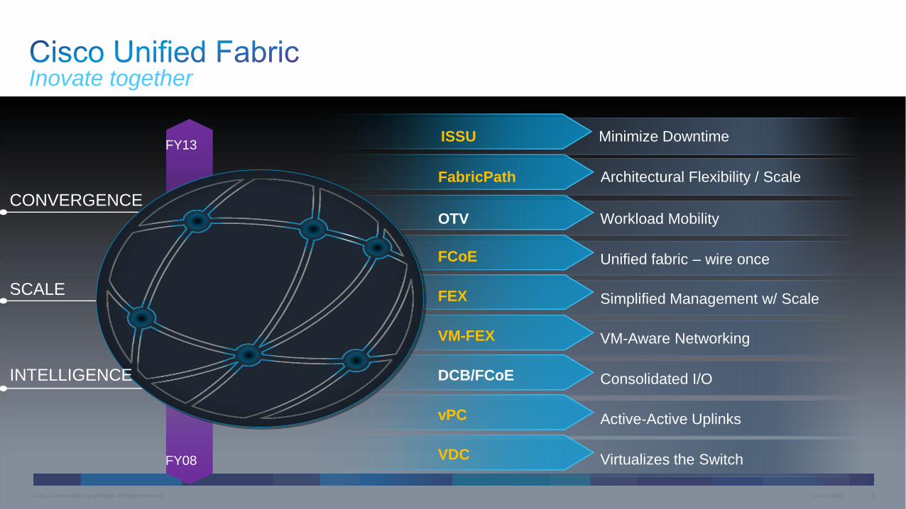
Inovate together
FY08
FY13
OTV
FCoE
FEX
VM-FEX
DCB/FCoE
vPC
VDC
Workload Mobility
Unified fabric – wire once
Simplified Management w/ Scale
VM-Aware Networking
Consolidated I/O
Active-Active Uplinks
Virtualizes the Switch
Architectural Flexibility / Scale FabricPath
CONVERGENCE
SCALE
INTELLIGENCE
Minimize Downtime ISSU
Cisco Public 4 © 2011 Cisco and/or its affiliates. All rights reserved.

© 2011 Cisco and/or its affiliates. All rights reserved. Cisco Public 5
Because customers request it!
• Application requirement – Clusters, vMotion
• Plug and play
• No addressing
• Easy server provisioning
• Virtual machine mobility
• Inspiration from SAN fabric
5

© 2011 Cisco and/or its affiliates. All rights reserved. Cisco Public 6
Just extend Spanning-Tree to the whole network
STP
L3
L2
6
? ? ?
© 2011 Cisco and/or its affiliates. All rights reserved. Cisco Public 7
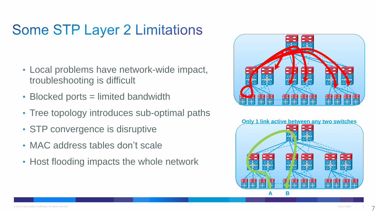
• Local problems have network-wide impact, troubleshooting is difficult
• Blocked ports = limited bandwidth
• Tree topology introduces sub-optimal paths
• STP convergence is disruptive
• MAC address tables don’t scale
• Host flooding impacts the whole network
7
Only 1 link active between any two switches
A B

© 2011 Cisco and/or its affiliates. All rights reserved. Cisco Public 8
Spanning Tree Virtual Port Channel / VSS FabricPath
POD
Bandwidth
Active Paths
Up to 10 Tbps Up to 20 Tbps Up to 160 Tbps
Single Dual 16 Way
Infrastructure Virtualization and Capacity
Layer 2 Scalability
© 2011 Cisco and/or its affiliates. All rights reserved. Cisco Public 9
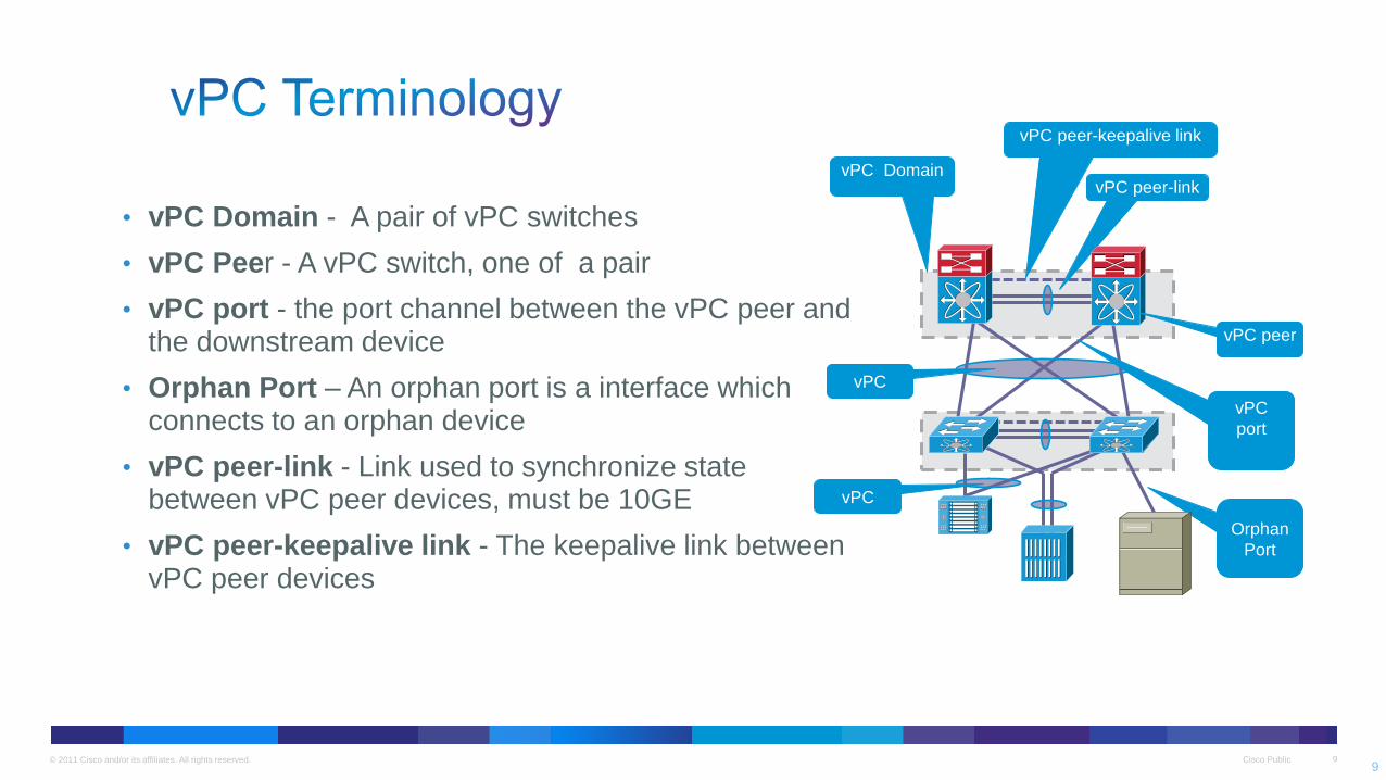
• vPC Domain - A pair of vPC switches
• vPC Peer - A vPC switch, one of a pair
• vPC port - the port channel between the vPC peer and the downstream device
• Orphan Port – An orphan port is a interface which connects to an orphan device
• vPC peer-link - Link used to synchronize state between vPC peer devices, must be 10GE
• vPC peer-keepalive link - The keepalive link between vPC peer devices
vPC
member
port
vPC
vPC
port
vPC peer-link
vPC peer
vPC Domain
vPC
Orphan
Port
9
vPC peer-keepalive link
© 2011 Cisco and/or its affiliates. All rights reserved. Cisco Public 10
MCEC
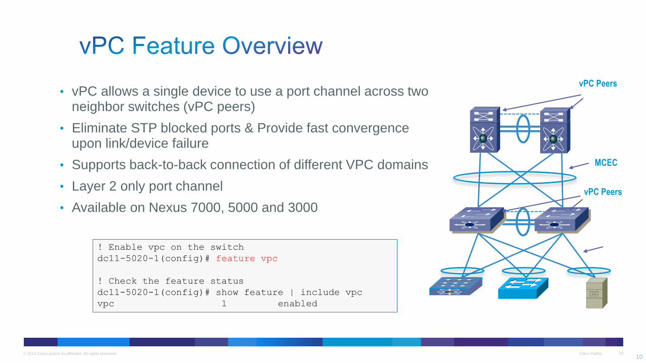
! Enable vpc on the switch
dc11-5020-1(config)# feature vpc
! Check the feature status
dc11-5020-1(config)# show feature | include vpc
vpc 1 enabled
vPC Peers
• vPC allows a single device to use a port channel across two neighbor switches (vPC peers)
• Eliminate STP blocked ports & Provide fast convergence upon link/device failure
• Supports back-to-back connection of different VPC domains
• Layer 2 only port channel
• Available on Nexus 7000, 5000 and 3000
MCEC
vPC Peers
10
© 2011 Cisco and/or its affiliates. All rights reserved. Cisco Public 11
vPC
member
port
vPC
member
port
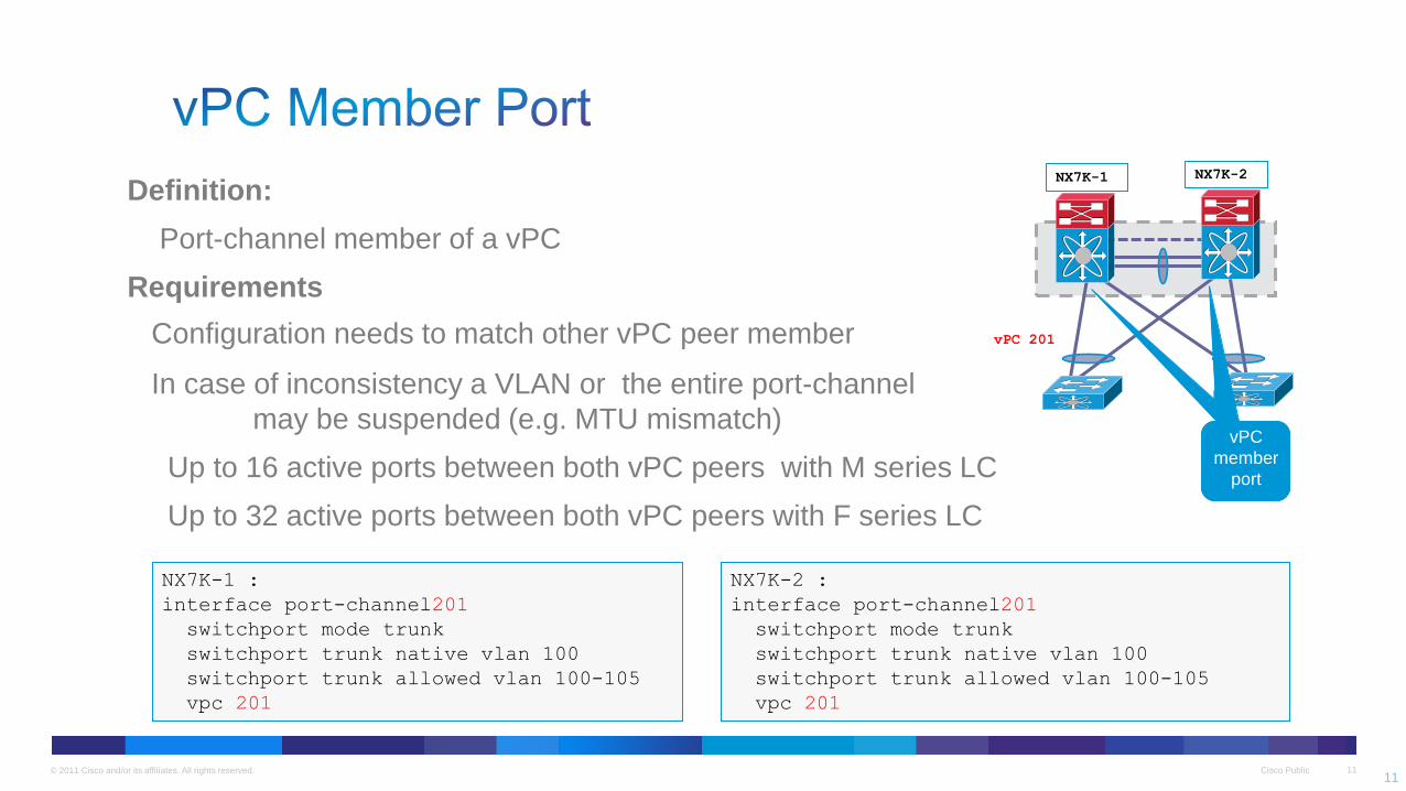
NX7K-2 :
interface port-channel201
switchport mode trunk
switchport trunk native vlan 100
switchport trunk allowed vlan 100-105
vpc 201
NX7K-1 :
interface port-channel201
switchport mode trunk
switchport trunk native vlan 100
switchport trunk allowed vlan 100-105
vpc 201
NX7K-1 NX7K-2
vPC 201
Definition:
Port-channel member of a vPC
Requirements
Configuration needs to match other vPC peer member
In case of inconsistency a VLAN or the entire port-channel
may be suspended (e.g. MTU mismatch)
Up to 16 active ports between both vPC peers with M series LC
Up to 32 active ports between both vPC peers with F series LC
11

© 2011 Cisco and/or its affiliates. All rights reserved. Cisco Public 12
SW3 SW4
vPC1 vPC2
vPC_PLink
vPC Peer-keepalive
Keepalive Heartbeat
Secondary vPC
P S
S
P Primary vPC
Suspend secondary
vPC Member Ports
vPC peer-link failure (link loss):
Check active status of the remote vPC peer via vPC peer-keepalive link (UDP heartbeat)
If both peers are active, then Secondary vPC peer will disable all vPCs to avoid Dual-Active
Data will automatically forward down remaining active port channel ports
Orphan devices connected to secondary peer will be isolated
12
dc11-5020-3(config-vpc-domain)# role priority ?
<1-65535> Specify priority value
dc11-5020-3# sh vpc
<snip>
vPC role : secondary, operational primary

© 2011 Cisco and/or its affiliates. All rights reserved. Cisco Public 13
vPC Domain
13
Data-Plane vs. Control-Plane Loop control
- vPC peers can forward all traffic locally
- Peer-link does not typically forward data packets (control plane extension)
- Traffic on the Peer-link is marked and not allowed to egress on a vPC
- Exception for single-sided vPC failures
- Exception for Orphan ports
- Implications for Dynamic L3 & Mcast
- VSS merging control-plane
VSS VPC 5k VPC 7k
L3 FHRP ok ok ok
L3 Dyn. ok ok Q1Y13
L3 Mcast ok
L2 ok ok ok

© 2011 Cisco and/or its affiliates. All rights reserved. Cisco Public 14
Enhanced vPC
FCoE + Ethernet traffic
FCoE + Ethernet traffic
Ethernet only traffic
• Ethernet traffic gets equally distributed on FEX uplinks to both switches
• FCoE traffic is pinned only to uplink to one switch (for fabric isolation)
• Uplink carrying FCoE end up carrying more traffic (50% Eth + FCoE) than other uplink
(50% Eth)
14
© 2011 Cisco and/or its affiliates. All rights reserved. Cisco Public 15
FP Port
FP VLAN’s
vPC+
FP
CE Port
CE VLAN’s
vPC
CE
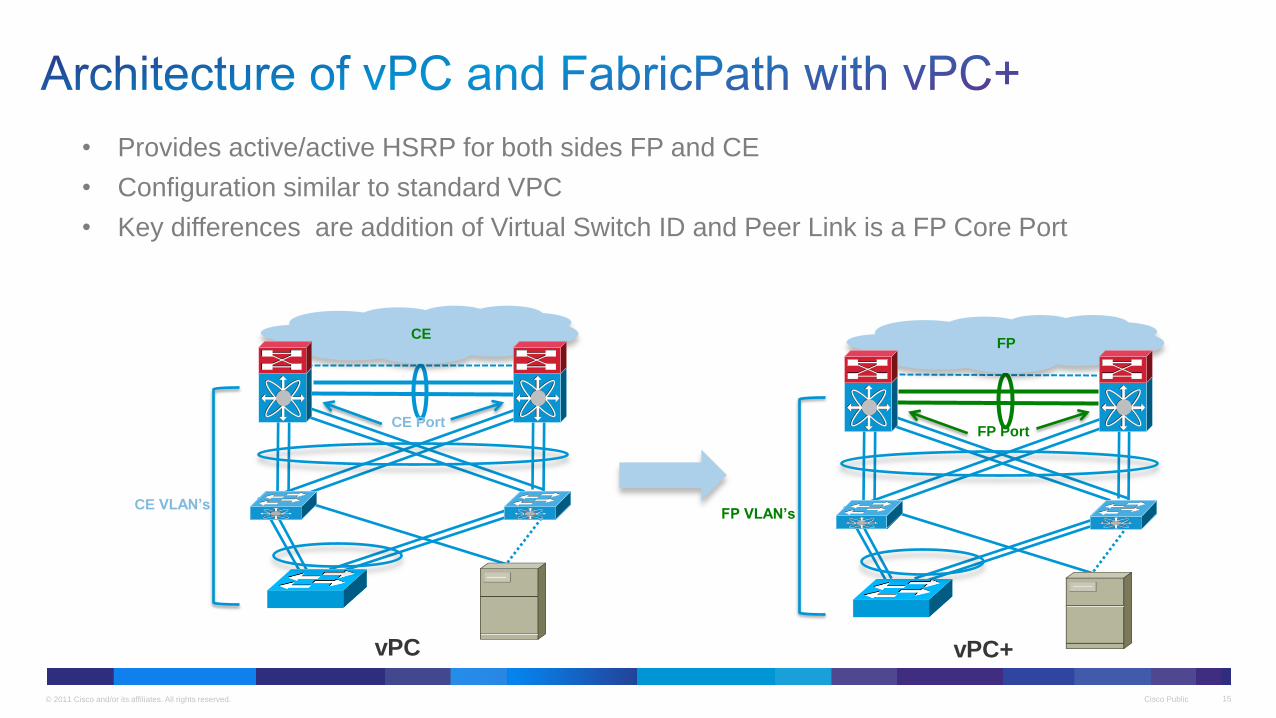
• Provides active/active HSRP for both sides FP and CE
• Configuration similar to standard VPC
• Key differences are addition of Virtual Switch ID and Peer Link is a FP Core Port

© 2011 Cisco and/or its affiliates. All rights reserved. Cisco Public 16
IRF - Intelligent Resilient Framework.
• No STP. Can support fixed switch stacking from 2 to 9 switches. (Broadcom) (FlexStack - 2960 equivalent)
• More switches in stack deliver unacceptable failover times.
• If a redundant Sup. fails, you lose 50% switching capacity.
Failover Results Summary
Quad Supervisor
vPC IRF
Unicast NS Failover Time (s) 0.284 436.1
Unicast SN Failover Time (s) 0.056 441.4
Multicast Failover Time (s) 0.083 504.2
7 minutes
7 minutes
8 minutes
© 2011 Cisco and/or its affiliates. All rights reserved. Cisco Public 17
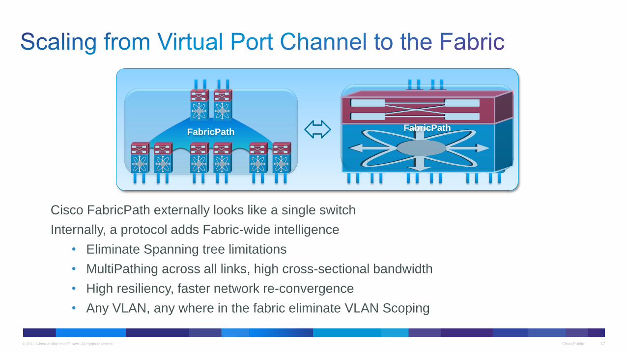
Cisco FabricPath externally looks like a single switch
Internally, a protocol adds Fabric-wide intelligence
• Eliminate Spanning tree limitations
• MultiPathing across all links, high cross-sectional bandwidth
• High resiliency, faster network re-convergence
• Any VLAN, any where in the fabric eliminate VLAN Scoping
FabricPath FabricPath
© 2011 Cisco and/or its affiliates. All rights reserved. Cisco Public 18
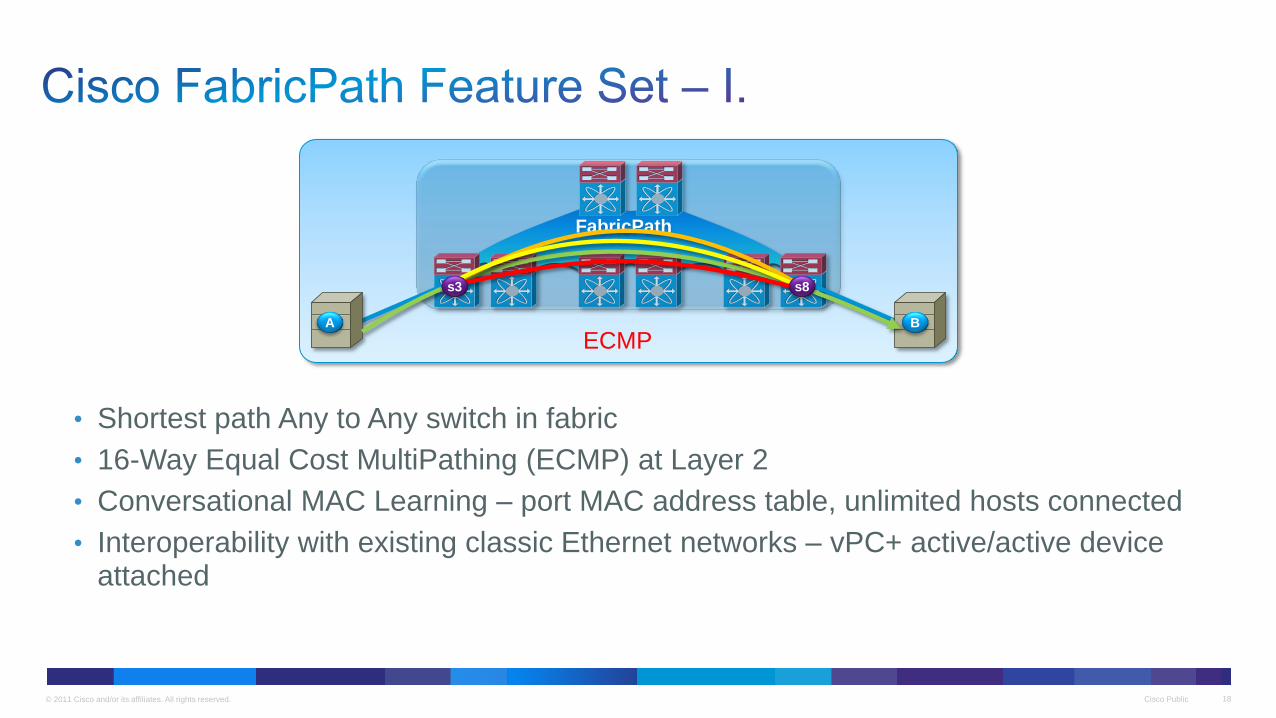
• Shortest path Any to Any switch in fabric
• 16-Way Equal Cost MultiPathing (ECMP) at Layer 2
• Conversational MAC Learning – port MAC address table, unlimited hosts connected
• Interoperability with existing classic Ethernet networks – vPC+ active/active device attached
FabricPath
A B
s3 s8
ECMP
© 2011 Cisco and/or its affiliates. All rights reserved. Cisco Public 19
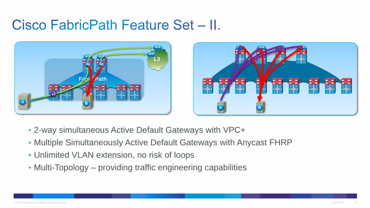
• 2-way simultaneous Active Default Gateways with VPC+
• Multiple Simultaneously Active Default Gateways with Anycast FHRP
• Unlimited VLAN extension, no risk of loops
• Multi-Topology – providing traffic engineering capabilities
FabricPath
A
s3
dg dg L3
B A B

© 2011 Cisco and/or its affiliates. All rights reserved. Cisco Public 20
• IS-IS assigns addresses to all FabricPath switches automatically • Compute shortest, pair-wise paths • Support equal-cost paths between any FabricPath switch pairs
L1
FabricPath
Routing Table
L2 L3
L4
FabricPath
Switch IF
S10 L1
S20 L2
S30 L3
S40 L4
S200 L1, L2, L3, L4
… …
S400 L1, L2, L3, L4
S100 S200 S300 S400
S10 S20 S30 S40
20
Spine Switch
Leaf Switch
Clos Fabric

© 2011 Cisco and/or its affiliates. All rights reserved. Cisco Public 21
• The association MAC address/Switch ID is maintained at the edge • Traffic is encapsulated across the Fabric
Classical Ethernet (CE)
S10 S20 S30 S40
S100 S200 S300
1/1 S300: CE MAC
Address Table
MAC IF
B 1/2
… …
MAC IF
B 1/2
A S100
1/2
S300: FabricPath
Routing Table
Switch IF
… …
S100 L1, L2, L3, L4
FabricPath (FP)
Switch ID space:
Routing decisions
are made based on
the FabricPath
routing table
MAC adress space:
Switching based on
MAC address tables
S100 S300 A B
A B
21
© 2011 Cisco and/or its affiliates. All rights reserved. Cisco Public 22
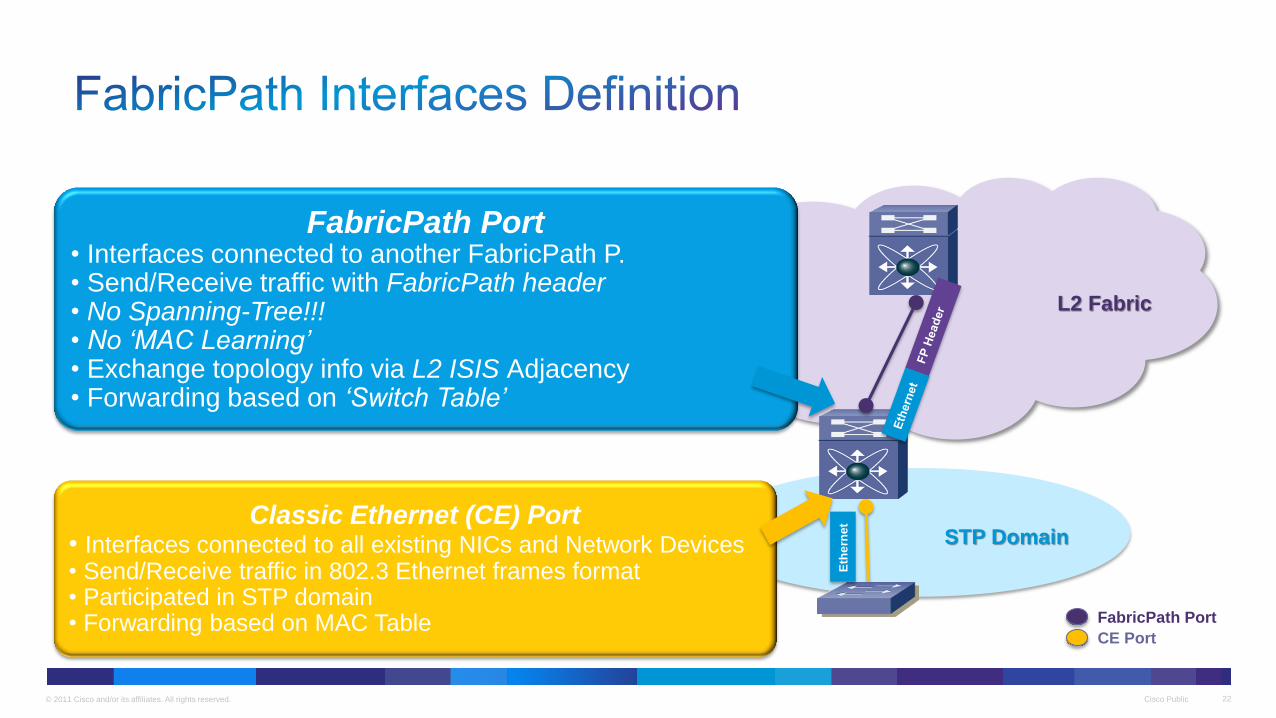
FabricPath Port • Interfaces connected to another FabricPath P. • Send/Receive traffic with FabricPath header • No Spanning-Tree!!! • No ‘MAC Learning’ • Exchange topology info via L2 ISIS Adjacency • Forwarding based on ‘Switch Table’
Classic Ethernet (CE) Port • Interfaces connected to all existing NICs and Network Devices • Send/Receive traffic in 802.3 Ethernet frames format • Participated in STP domain • Forwarding based on MAC Table
STP Domain
L2 Fabric
Eth
ern
et
FabricPath Port
CE Port
© 2011 Cisco and/or its affiliates. All rights reserved. Cisco Public 23
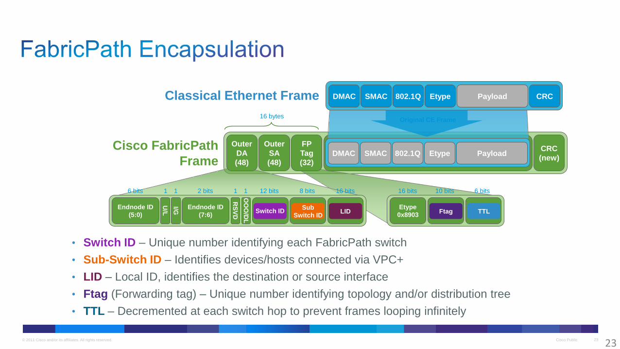
Cisco FabricPath
Frame
Classical Ethernet Frame
• Switch ID – Unique number identifying each FabricPath switch
• Sub-Switch ID – Identifies devices/hosts connected via VPC+
• LID – Local ID, identifies the destination or source interface
• Ftag (Forwarding tag) – Unique number identifying topology and/or distribution tree
• TTL – Decremented at each switch hop to prevent frames looping infinitely
DMAC SMAC 802.1Q Etype CRC Payload
DMAC SMAC 802.1Q Etype Payload CRC
(new)
FP
Tag
(32)
Outer
SA
(48)
Outer
DA
(48)
Endnode ID
(5:0)
Endnode ID
(7:6)
U/L
I/G
RS
VD
OO
O/D
L
Etype
0x8903
6 bits 1 1 2 bits 1 1 12 bits 8 bits 16 bits 10 bits 6 bits 16 bits
Switch ID Sub
Switch ID Ftag TTL LID
Original CE Frame 16 bytes
23
© 2011 Cisco and/or its affiliates. All rights reserved. Cisco Public 24
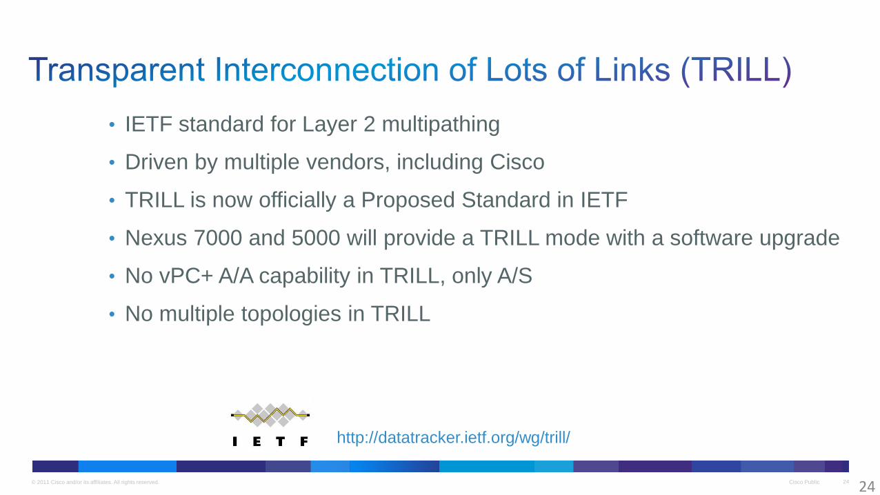
• IETF standard for Layer 2 multipathing
• Driven by multiple vendors, including Cisco
• TRILL is now officially a Proposed Standard in IETF
• Nexus 7000 and 5000 will provide a TRILL mode with a software upgrade
• No vPC+ A/A capability in TRILL, only A/S
• No multiple topologies in TRILL
http://datatracker.ietf.org/wg/trill/
24
© 2011 Cisco and/or its affiliates. All rights reserved. Cisco Public 25
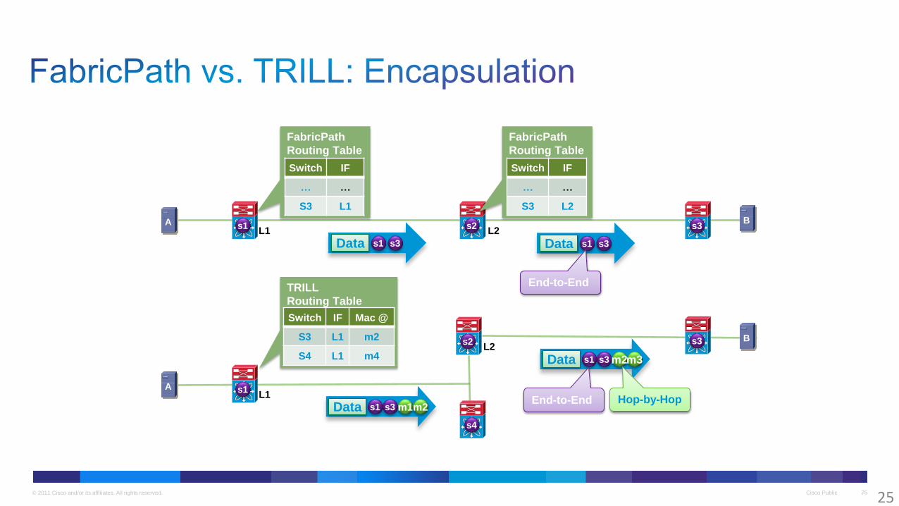
A s3 s2 s1 B
FabricPath
Routing Table
Switch IF
… …
S3 L1
Data s1 s3
L1
FabricPath
Routing Table
Switch IF
… …
S3 L2
L2
Data s1 s3
A
s3
s1
B
TRILL
Routing Table
Switch IF Mac @
S3 L1 m2
S4 L1 m4
L1
L2
s4
s2
Data s1 s3 m1 m2
Data s1 s3 m2 m3
Hop-by-Hop End-to-End
End-to-End
25
© 2011 Cisco and/or its affiliates. All rights reserved. Cisco Public 26
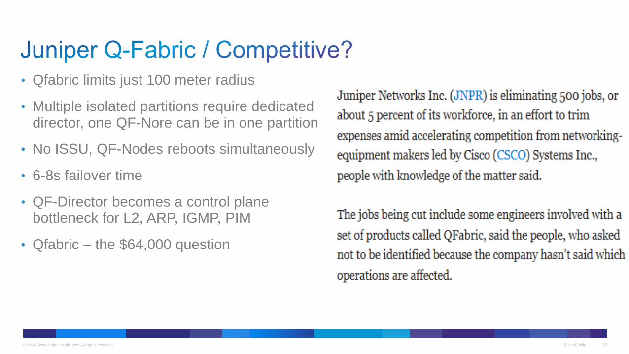
• Qfabric limits just 100 meter radius
• Multiple isolated partitions require dedicated director, one QF-Nore can be in one partition
• No ISSU, QF-Nodes reboots simultaneously
• 6-8s failover time
• QF-Director becomes a control plane bottleneck for L2, ARP, IGMP, PIM
• Qfabric – the $64,000 question
Co
ntr
ol
Netw
ork
(A
)
Co
ntr
ol
Netw
ork
(B
)
QF-Node #1 QF-Node #128
QF-Interconnects
12
8 c
op
pe
r c
ab
les
12
8 c
op
pe
r c
ab
les
Heartbeats
A A S S
No Heartbeats QF-Director QF-Director
A A S S A A S S A A S S A A S S
Switch Fabrics
Linecards
Backplane Circuit Traces
Cisco Public 27 © 2011 Cisco and/or its affiliates. All rights reserved.

© 2011 Cisco and/or its affiliates. All rights reserved. Cisco Public 28
• Consolidation of Core and Aggregation while maintaining network hierarchy
• No reduction in port count or links but fewer physical switches
Copper Twinax cables (CX-1) provide a low cost 10G interconnect option
2
8
Core
Aggregation
Access
Core Core
Agg Agg
© 2011 Cisco and/or its affiliates. All rights reserved. Cisco Public 29
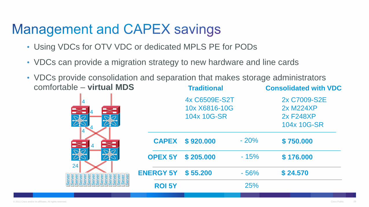
• Using VDCs for OTV VDC or dedicated MPLS PE for PODs
• VDCs can provide a migration strategy to new hardware and line cards
• VDCs provide consolidation and separation that makes storage administrators comfortable – virtual MDS
4
4
4 4
4
24
Serv
er
Serv
er
Serv
er
Serv
er
Serv
er
Serv
er
Serv
er
Serv
er
Serv
er
Serv
er
Serv
er
Serv
er
Serv
er
Sever
Serv
er
4x C6509E-S2T
10x X6816-10G
104x 10G-SR
2x C7009-S2E
2x M224XP
2x F248XP
104x 10G-SR
- 20% CAPEX
OPEX 5Y $ 205.000 $ 176.000 - 15%
$ 55.200 $ 24.570 - 56% ENERGY 5Y
Traditional Consolidated with VDC
$ 920.000 $ 750.000
25% ROI 5Y
© 2011 Cisco and/or its affiliates. All rights reserved. Cisco Public 30
VDC-8
VDC-4
VDC-3
VDC-2
VDC-1
Ad
min
VD
C
. . .
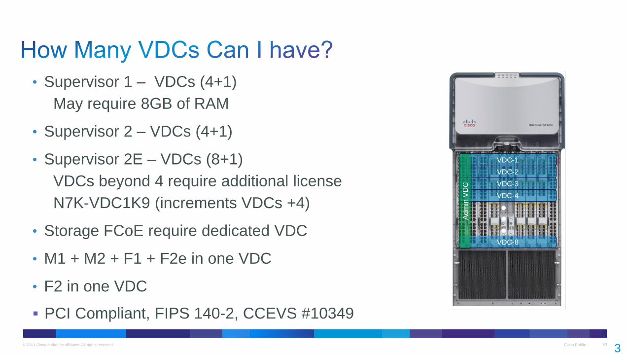
• Supervisor 1 – VDCs (4+1)
May require 8GB of RAM
• Supervisor 2 – VDCs (4+1)
• Supervisor 2E – VDCs (8+1)
VDCs beyond 4 require additional license
N7K-VDC1K9 (increments VDCs +4)
• Storage FCoE require dedicated VDC
• M1 + M2 + F1 + F2e in one VDC
• F2 in one VDC
PCI Compliant, FIPS 140-2, CCEVS #10349
3
0
© 2011 Cisco and/or its affiliates. All rights reserved. Cisco Public 31
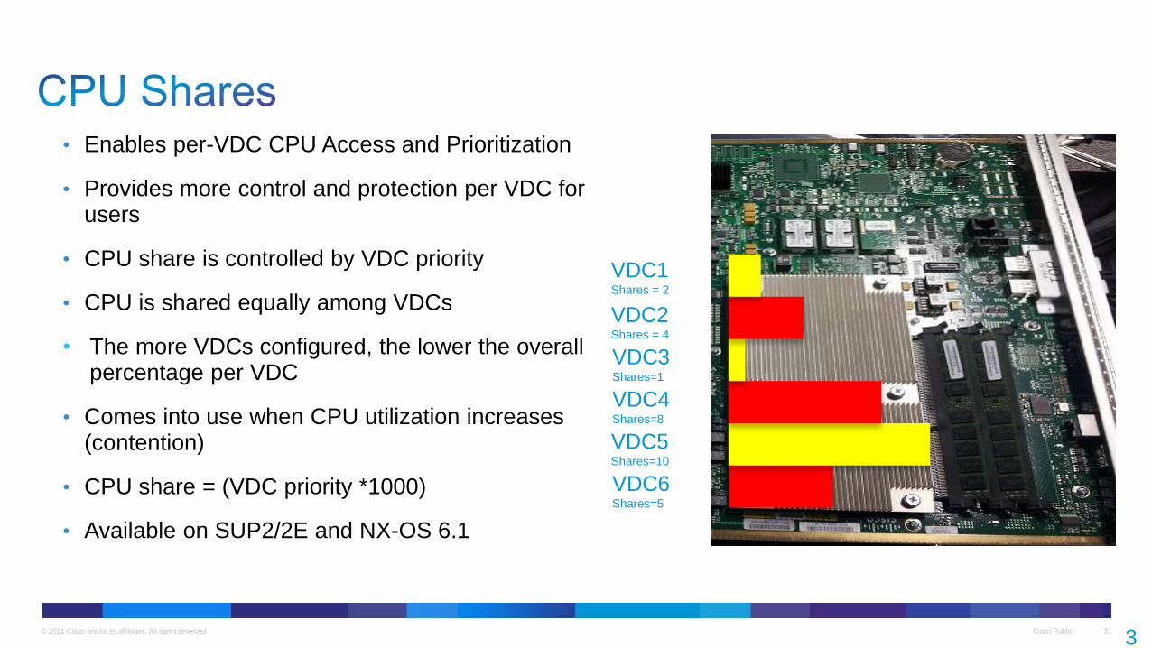
• Enables per-VDC CPU Access and Prioritization
• Provides more control and protection per VDC for users
• CPU share is controlled by VDC priority
• CPU is shared equally among VDCs
• The more VDCs configured, the lower the overall percentage per VDC
• Comes into use when CPU utilization increases (contention)
• CPU share = (VDC priority *1000)
• Available on SUP2/2E and NX-OS 6.1
3
1
VDC1 Shares = 2
VDC2 Shares = 4
VDC3 Shares=1
VDC4 Shares=8
VDC5 Shares=10
VDC6 Shares=5
© 2011 Cisco and/or its affiliates. All rights reserved. Cisco Public 32
Huawei S9700 or S9300 Series
• Do not match VDC like capability
Huawei 12800 Series
• Virtual System (VS)
• Maximum of 1:8 VS on one physical chassis (means 8 virtual instances)
• Presented at Interop in Las Vegas May of 2012 – demo version
• Product will be available at the end of 2012
• TRILL, IEEE DCB, FCoE, CSC Clustering
Must have seen it before, maybe on previous slide? Bingo…
© 2011 Cisco and/or its affiliates. All rights reserved. Cisco Public 33
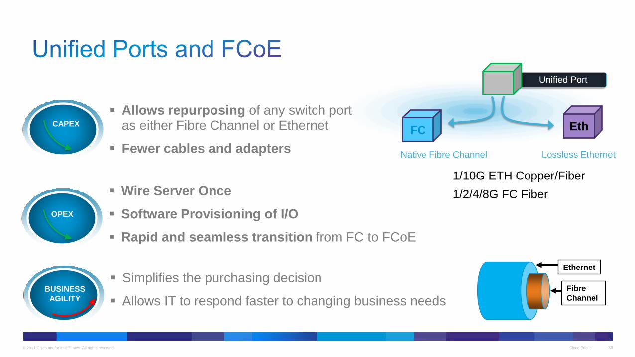
Allows repurposing of any switch port as either Fibre Channel or Ethernet
Fewer cables and adapters
Wire Server Once
Software Provisioning of I/O
Rapid and seamless transition from FC to FCoE
Unified Port
Native Fibre Channel
FC Eth
Lossless Ethernet
BUSINESS
AGILITY
OPEX
CAPEX
Simplifies the purchasing decision
Allows IT to respond faster to changing business needs
1/10G ETH Copper/Fiber
1/2/4/8G FC Fiber
Fibre
Channel
Ethernet
© 2011 Cisco and/or its affiliates. All rights reserved. Cisco Public 34
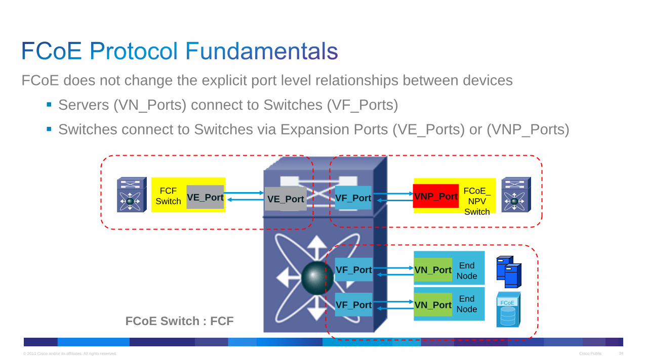
FCoE does not change the explicit port level relationships between devices
Servers (VN_Ports) connect to Switches (VF_Ports)
Switches connect to Switches via Expansion Ports (VE_Ports) or (VNP_Ports)
VE_Port
VF_Port
VF_Port
VE_Port
VN_Port
VN_Port
FCoE_
NPV
Switch
VF_Port VNP_Port FCF
Switch
End
Node
End
Node
FCoE Switch : FCF
FCoE
© 2011 Cisco and/or its affiliates. All rights reserved. Cisco Public 35
Converged FCoE link
Dedicated FCoE link
FC
Ethernet
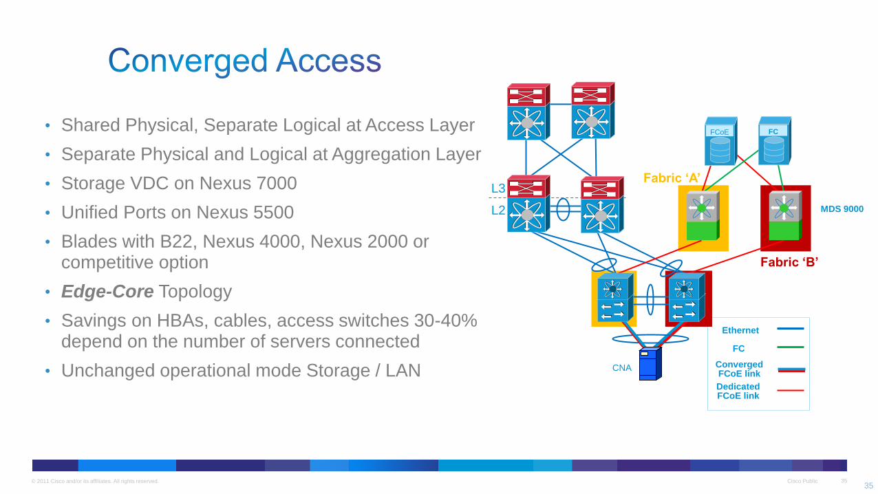
• Shared Physical, Separate Logical at Access Layer
• Separate Physical and Logical at Aggregation Layer
• Storage VDC on Nexus 7000
• Unified Ports on Nexus 5500
• Blades with B22, Nexus 4000, Nexus 2000 or competitive option
• Edge-Core Topology
• Savings on HBAs, cables, access switches 30-40% depend on the number of servers connected
• Unchanged operational mode Storage / LAN
Fabric ‘B’
L2
L3
CNA
Fabric ‘A’
FC FCoE
MDS 9000
35

© 2011 Cisco and/or its affiliates. All rights reserved. Cisco Public 36
Access and Aggregation share physical switches
All switches are FCoE FCF switches
Storage VDC Agg, Nexus 5k at acces
SAN can utilize higher performance, higher density, lower cost Ethernet switches for the aggregation/core
Edge-Core-Edge Topology
Access for new 10G CEE servers to old FC storage/tape
…
…
L2
L3
CNA FC FCoE
FCF FCF
FCF
VE
LAN/SAN
Converged FCoE link Dedicated FCoE link
FC
Ethernet
36
FCoE

© 2011 Cisco and/or its affiliates. All rights reserved. Cisco Public 37
Brocade FCOE10-24 Blade for DCX and DCX-4S
• No VE_port support -> limitation of multi-hop FCoE, DC interconnect over FCoE
• No ISSU support
• No L3 support, ISL Trunk max. 8 ports
Brocade 8000 Fixed Top-Of-Rack Switch
• No Unified Ports, ability to turn switch into FC regular switch
• No STP neither RSTP, no FCoE N-Port Virtualization
• No L3 support, ISL Trunk max. 8 ports

© 2011 Cisco and/or its affiliates. All rights reserved. Cisco Public 38
Distributed High Density Edge
Switching System
(up to 4096 virtual Ethernet
interfaces)
+
Cisco Nexus® 2000 FEX
Cisco Nexus® 5500
Cisco Nexus® 2000 FEX
Cisco Nexus® 7000
+

© 2011 Cisco and/or its affiliates. All rights reserved. Cisco Public 39
Fabric Extender Technology (FEX)
Single point of
management
IEEE 802.1BR*
VM-FEX
Adapter FEX
Cisco Nexus® 2000 Series
or B22 Fabric Blade Extender
IEEE 802.1BR*
IEEE 802.1BR*
Nexus 2000/B22 FEX
• Consolidates network management
• FEX managed as remote line card
• Extends cisco unified fabric into OEM partner blade chassis
Adapter FEX
• Consolidates multiple 1GbE interface into a single 10GbE interface
• Extends network into server
VM-FEX
• Consolidates virtual and physical network
• Each VM gets a dedicated port on switch
Distributed Modular System for Top of Rack Distributed Modular System for Physical Server—Logical Adapter Partitioning Distributed Modular System for Virtual Machine
Fabric Extender Technology–VM Awareness to Physical Network Fabric Extender Technology – Adapter virtualization
• Single point of policy
• Single point of management
• Reduction in cables
• Consistency across rack and
blade servers
• Interoperable—standards-based
ONE NETWORK Parent switch to top of rack
ONE NETWORK Parent switch to adapter
ONE NETWORK Virtual same as physical

Cisco Public 40 © 2011 Cisco and/or its affiliates. All rights reserved.
© 2011 Cisco and/or its affiliates. All rights reserved. Cisco Public 41
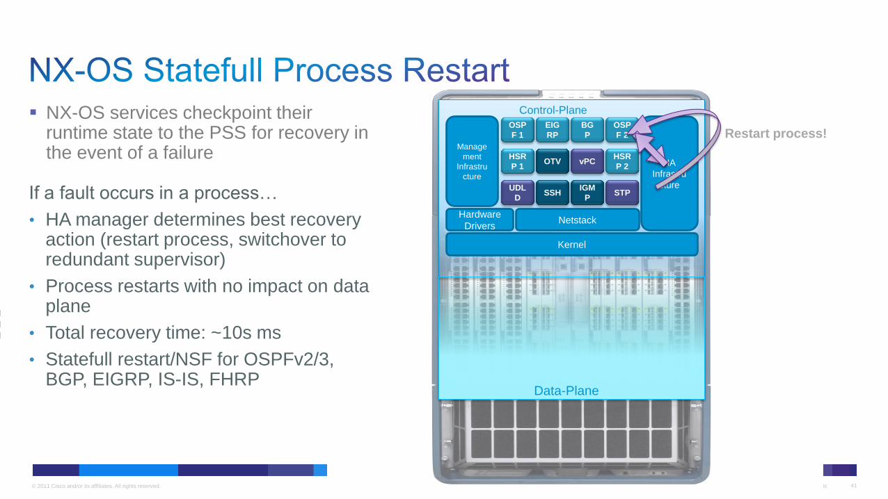
If a fault occurs in a process…
• HA manager determines best recovery action (restart process, switchover to redundant supervisor)
• Process restarts with no impact on data plane
• Total recovery time: ~10s ms
• Statefull restart/NSF for OSPFv2/3, BGP, EIGRP, IS-IS, FHRP
Restart process!
Kernel
Netstack
Manage
ment
Infrastru
cture
Hardware
Drivers
HA
Infrastru
cture UDL
D SSH
IGM
P STP
HSR
P 1 OTV vPC
HSR
P 2
OSP
F 1
EIG
RP
BG
P
OSP
F 2
Control-Plane
Data-Plane
NX-OS services checkpoint their runtime state to the PSS for recovery in the event of a failure
© 2011 Cisco and/or its affiliates. All rights reserved. Cisco Public 42
Release 4.0 Release 5.1
Linux Kernel O
SP
F
BG
P
PIM
etc
.
HA Manager
N7K Data Plane
Linux Kernel
HA Manager
Active
I/O Module Images
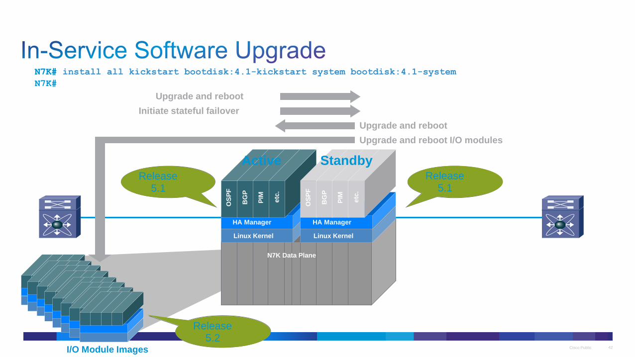
Upgrade and reboot
Release 4.0 Release 5.1
OS
PF
BG
P
PIM
etc
.
Standby
Initiate stateful failover
Upgrade and reboot
Upgrade and reboot I/O modules
Active
Standby
Needed for animation, don’t
remove!
N7K# install all kickstart bootdisk:4.1-kickstart system bootdisk:4.1-system N7K#
N7K#
Release 4.0 Release 5.2
© 2011 Cisco and/or its affiliates. All rights reserved. Cisco Public 43
foo
Layer 3
OSPF 300
OSPF Area 0
OSPF Hello 1s
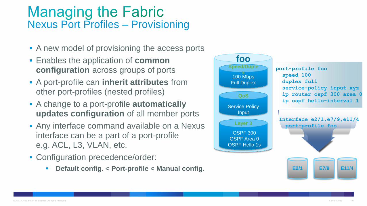
A new model of provisioning the access ports
Enables the application of common configuration across groups of ports
A port-profile can inherit attributes from other port-profiles (nested profiles)
A change to a port-profile automatically updates configuration of all member ports
Any interface command available on a Nexus interface can be a part of a port-profile e.g. ACL, L3, VLAN, etc.
Configuration precedence/order:
Default config. < Port-profile < Manual config.
Speed/Duple
x 100 Mbps
Full Duplex
QoS
Service Policy
Input
E2/1 E7/9 E11/4
port-profile foo
speed 100
duplex full
service-policy input xyz
ip router ospf 300 area 0
ip ospf hello-interval 1
Interface e2/1,e7/9,e11/4
port-profile foo
Nexus Port Profiles – Provisioning

© 2011 Cisco and/or its affiliates. All rights reserved. Cisco Public 44
Potential growth in System Control Plane Capabilities
On-Box Scripting
• TCL
• PERL
• Python
XML Mgmt.
Interface
• NETCONF & YANG models
• XMPP, REST
onePK
• SDK/APIs in multiple languages.
• Extensibility & Programmability
Network
Automation
Network Admin
Quick automation
Manual or home grown scripts
NM App Developer
NM app/OSS
Standards driven
Typical net mgmt.
App Developer
VARs/Partners/CU
Prog. APIs
Extend and leverage
© 2011 Cisco and/or its affiliates. All rights reserved. Cisco Public 45
© 2011 Cisco and/or its affiliates. All rights reserved. Cisco Public 46
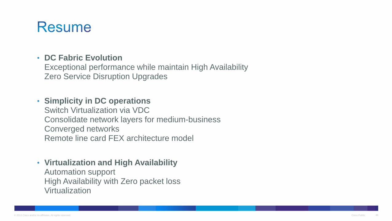
• DC Fabric Evolution Exceptional performance while maintain High Availability Zero Service Disruption Upgrades
• Simplicity in DC operations Switch Virtualization via VDC Consolidate network layers for medium-business Converged networks Remote line card FEX architecture model
• Virtualization and High Availability Automation support High Availability with Zero packet loss Virtualization
Cisco Public 47 © 2011 Cisco and/or its affiliates. All rights reserved.
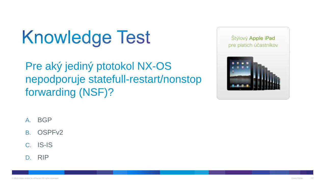
Pre aký jediný ptotokol NX-OS
nepodporuje statefull-restart/nonstop
forwarding (NSF)?
A. BGP
B. OSPFv2
C. IS-IS
D. RIP
Thank you.