dash8-200/300 - communications · 2012. 6. 27. · particular frequency using 8,33 khz, the...
TRANSCRIPT

HF, UHF and FM not installed
COMMUNICATION
CONTROLS AND INDICATORS
Audio control panel (ACP)
Dash8-200/300 - Communications
Page 1

Interphone Control Unit (ICU)
Dash8-200/300 - Communications
Page 2

Flight attendant's handset and control unit
Dash8-200/300 - Communications
Page 3

Dash8-200/300 - Communications
Page 4

GROUND CREWINDICATOR LIGHTS -FWD ground crewconnected to left handside nose interphonejack. -AFT ground crewconnected tointerphone jack inrefuel/defuel panel
PILOTS NOSEWHEEL STEERING CONTROL WHEELPTT MICROPHONESWITCH. -Keys mic as selectedon audio control panel
PTT/INPH MICROPHONE SWITCH PUSH-TO-TALK SWITCH (PTT) -PTT keys mic as selected by rotaryMIC selector switch on audio controlpanel. INTERPHONE SWITCH (INPH) -INPH connects mic to interphonesystem (flight deck and ground crewstations)
Left pilot’s side console
Left control wheel - (right opposite)
RIGHT PILOT’S SIDE PANEL INPH/XMITMICROPHONE SWITCH INPH – connects mic to interphone systemXMIT – keys mic as selected on audiocontrol panel
RIGHT
Dash8-200/300 - Communications
Page 5

behind either pilot’s seat
Observer’s communication panel / microphone and headphone jacks
Dash8-200/300 - Communications
Page 6
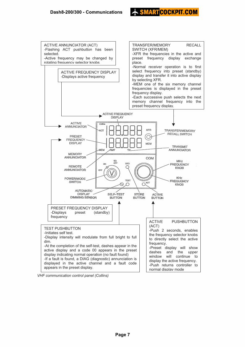
VHF communication control panel (Collins)
ACTIVE ANNUNCIATOR (ACT) -Flashing ACT pushbutton has beenselected. -Active frequency may be changed byrotating frequency selector knobs
ACTIVE FREQUENCY DISPLAY-Displays active frequency
TRANSFER/MEMORY RECALLSWITCH (XFR/MEM) -XFR the frequencies in the active andpreset frequency display exchangeplace. -Normal receiver operation is to firstselect frequency into preset (standby)display and transfer it into active displayby selecting XFR. -MEM one of the six memory channelfrequencies is displayed in the presetfrequency display. -Each successive push selects the nextmemory channel frequency into thepreset frequency display.
PRESET FREQUENCY DISPLAY-Displays preset (standby)frequency
TEST PUSHBUTTON -Initiates self test. -Display intensity will modulate from full bright to fulldim. -At the completion of the self-test, dashes appear in theactive display and a code 00 appears in the presetdisplay indicating normal operation (no fault found) -If a fault is found, a DIAG (diagnostic) annunciation isdisplayed in the active channel and a fault codeappears in the preset display.
ACTIVE PUSHBUTTON(ACT) -Push 2 seconds, enablesthe frequency selector knobsto directly select the activefrequency. -Preset display will showdashes and the upperwindow will continue todisplay the active frequency. -Push returns controller tonormal display mode
Dash8-200/300 - Communications
Page 7

VHF communication control panel (Collins)
POWER/MODE SWITCH -Detented ON/OFF/SQ OFF. -OFF de-energizes thetransceiver -ON energizes the transceiver -SQ OFF disables the automaticsquelch circuits to provideaudible receiver output forsetting volume. -Volume is adjusted on the audiocontrol panel. -Reselect ON position forautomatic squelch operationafter volume level is set
FREQUENCY SELECTOR KNOBS -Changes standby frequency display -Numbers roll over at the upper and lowerfrequency limits -With ACT pushbutton selected, activefrequency is changed. OUTER KNOB changes the MHz portion ofthe display in 1 MHz increments. INNER KNOB changes the KHz portion ofthe display in 8.33 KHz increments.
TRANSMIT ANNUNCIATOR(TX) -Indicates transceiver istransmitting
STORE PUSHBUTTON (STO) -Allows up to six preset frequencies to be selectedand entered into the controller’s memory. -Select the desired frequency into preset frequencydisplay by rotating the frequency selector knobs. -Push active frequency displays the availablememory space (channel number) designated CH1through CH6. -The MEM position of the XFR/MEM switch may berepeatedly selected to advance through thechannel numbers to reach the desired channel forstoring the preset frequency. -Push commits the preset frequency to memory inthe selected memory position (channel number) -The controller will return to normal operation after5 seconds.
MEMORY ANNUCIATOR (MEM)-Indicates a stored frequency(channel) is being displayed inthe pre-select frequency window.
Dash8-200/300 - Communications
Page 8
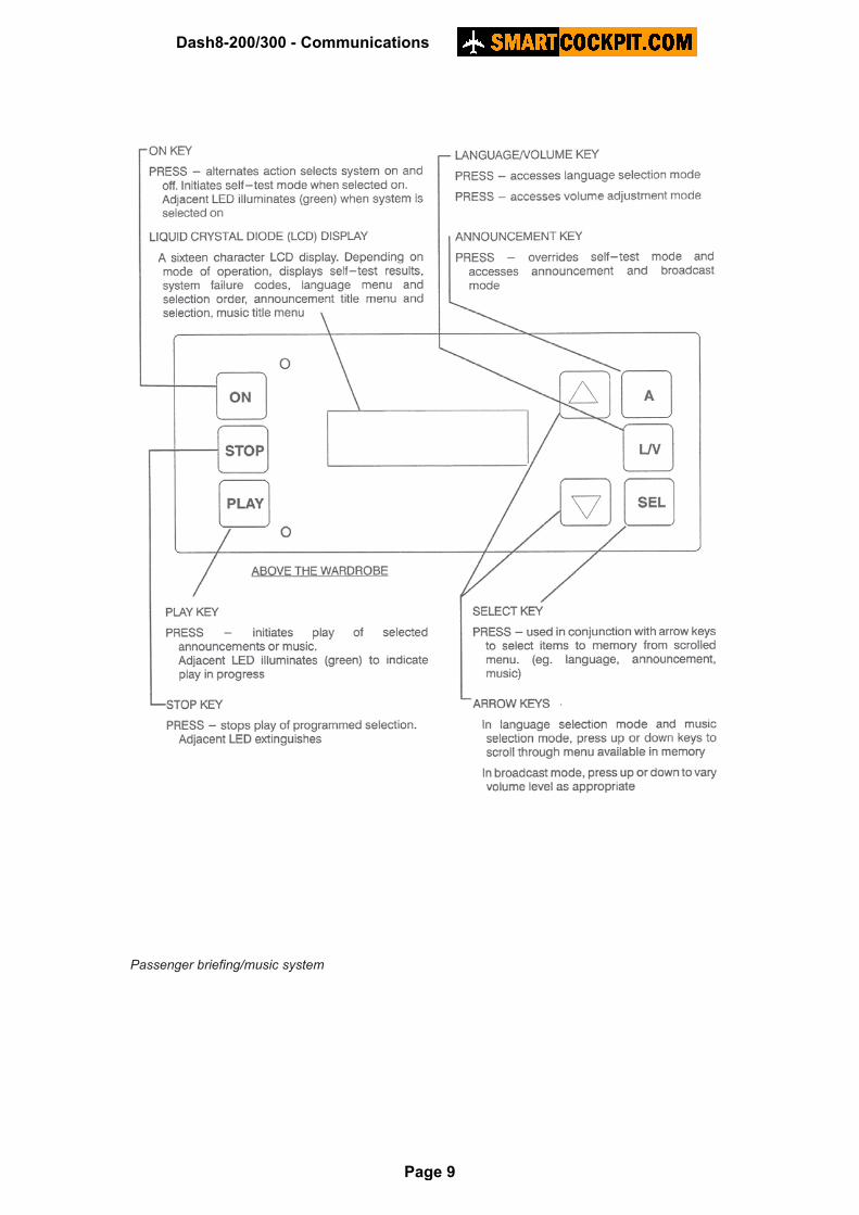
Passenger briefing/music system
Dash8-200/300 - Communications
Page 9

Solid state cockpit voice recorder monitor panel
Dash8-200/300 - Communications
Page 10

SYSTEM DESCRIPTION
Audio integration general
The audio integrating system provides the left pilot, right pilot and observer with individual control of transmission and reception of the communication radios and the capability to monitor the aircraft's navigation receivers. The audio integrating system also provides service interphone communication between the pilots, observer and two external ground crew stations. Audio control panel
Each pilot can manage his own communication requirements through an audio control panel (ACP). Two are located at the aft center console for the pilots, and one is located at the observer station. The ACP permits two way (transmit and receive) communication capability from the cabin interphone, service interphone, and VHF radio systems and one way (transmit only) communication capability through the passenger address. It also provides voice and identification monitoring of selected navigation aids. Receiver and cockpit loudspeaker volume is controlled from this panel. Microphone selections are made with a rotary type selector switch found on the panel. To enable operation of the quick-don oxygen mask Mic, the lever-locked toggle switch must be in the MASK position. Service interphone
Service interphone is for on-ground communication between cockpit and ground crew and is operated through the audio control panel. The system has two external ground crew stations (left hand side nose and refuel-defuel panel in the right nacelle). Ground crew indicator lights, located on the left pilot's side console, provide a visual indication of when the ground crew is plugged into either service interphone jack. Passenger address and cabin interphone system (PACIS)
The PACIS provides: A. Passenger address from the flight compartment or flight attendant stations. B. Private voice communication between the flight compartment and a flight attendants’
station and between the two flight attendants’ stations. C. Visual indication and aural chime for normal and emergency calls at each location. D. Emergency operation of items A) B) C) above from the battery bus in the event of aircraft
primary power failure.
Dash8-200/300 - Communications
Page 11

Passenger address system
The passenger address (PA) system allows cockpit crew and cabin attendants to make announcements throughout the cabin. Flight crew can make an announcement by selecting the rotary MIC selector on the audio control panel to the PA position, pushing the PA switch light on the interphone control unit and keying a PTT switch. The flight crew can terminate the PA mode by selecting another MIC position on the audio control panel. Cabin attendants use either of the attendant handsets for announcements by pushing the PA switchlight and keying the handset switch. This mode is cancelled by placing the handset in its cradle. Flight deck crew may monitor cabin attendants’ announcements by pushing the PA button on the interphone control unit. Cabin interphone system
The cabin interphone system permits communication between the cockpit and flight attendant stations. An interphone control unit, located on the forward centre console, initiates and draws attention to the call through a CALL switch light. A chime is generated in the PA amplifier (located on wardrobe shelf) and is heard in the headsets and cockpit speaker (if selected). By pressing the CALL switch light and selecting the MIC switch to PA on the audio control panel, the cockpit crew use the hand-held, headset-boom or mask mike to communicate with the flight attendants. The headset-boom and mask mic operate fulltime in the hot mic mode and are overridden by using the hand-held microphones. The flight crew receives attendant audio on their headsets and overhead cockpit speaker (if selected). Selection of cockpit speaker is made with the SPKR selector switch on the ACP. Keying a PTT switch mutes the onside speaker to prevent squealing. The flight attendants communicate between the two cabin stations or with the cockpit using handsets. Removing the handset from its cradle and pressing the CALL switch light on the attendant control unit initiate calls from the attendants to the flight crew. Communication between the two attendant stations is initiated by pressing the ATT switch light on the attendant control unit. The operation of attendant control unit at station #2 is similar to station #1. The cabin interphone system gives priority to modes selected from the flight compartment position.
Dash8-200/300 - Communications
Page 12

Team digital passenger announcement system
The team digital announcement system uses digitally recorded announcements and music stored on memory cards installed in the unit. The pre-recorded announcements and music are individually accessed and selected using the controls on the front of the unit. Up to four announcements languages may be programmed and sequenced for play from the memory cards. Once a program has been selected it will be retained for subsequent flights unless changed again. To operate the system proceed as follows: 1. ON key PRESS initiates self test. Successful self-test is annunciated as ‘TEST OK’ on
LCD display. System reverts to announcement selection and broadcast mode once self-test is successfully completed.
2. L/V key PRESS accesses language selection mode. 3. Use arrow keys to scroll through available memory for announcement titles and
languages. Use SEL key to select required messages and languages in the desired sequence. Messages titles and languages are displayed on the LCD. Languages are indicated on the menu by a single letter in parentheses included with the title of the message. Music is displayed as a menu item and may be selected for play by pressing SEL key.
4. PLAY key PRESS commences announcement sequence or music as selected. Adjust broadcast volume as follows: L/V key PRESS use arrow keys to adjust volume level as desired. Volume level is displayed on LCD. A single press is required if in language selection mode and a double press is required if in announcement mode. System will revert to announcement selection mode in thirty seconds following a volume adjustment.
Dash8-200/300 - Communications
Page 13

VHF communication system
Two VHF communication radios are installed. Each controller allows the selection of two independent frequencies; the desired frequency being selected into the standby display and then transferred to the active display. Individual transmit and audio control is provided through the respective audio control panel. Each VHF transceiver provides amplitude modulation (AM) voice communication in the 118.000 to 136.9917 MHz range in 8,33 kHz increments. The last ‘channel name’ displayed is 136.992, which is an actual frequency of 136.9917 MHz. To transmit and receive on a particular frequency using 8,33 kHz, the appropriate channel must be tuned to the frequency display. When using the 8,33 kHz spacing, the frequency being used to transmit and receive will not be the same as the channel selected on the frequency display. The transceiver units are installed in the avionics rack. Number 1 VHF antenna is located on the forward upper fuselage surface and Number 2 VHF antenna is located on the forward lower fuselage surface. VHF COMM controllers are located on the centre console. Number 1 controller is on the left and number 2 controller is on the right. The VHF COM controllers provide active frequency selection, standby frequency selection, and selection of frequencies from programmable channels. Frequency selection
Normally a frequency is selected in the preset display and then transferred to the active display for communication transceiver operation. Transfer is accomplished by momentarily selecting the XFR/MEM switch to the XFR position. When the switch is momentarily selected, the frequency in the active display and the frequency in the preset display exchange places. The active frequency may be set directly by pressing the ACT pushbutton for approximately two seconds and manually selecting the frequency with the frequency selector knobs. While the frequency is being manually set, an ACT annunciation flashes on the left side of the active frequency display. Pressing the ACT pushbutton a second time returns the active frequency to a normal display. Frequency selection is accomplished using the frequency selector knob on the face of the control panel. The larger of the two concentric knobs changes the MHz portion of the display in 1 MHz increments. The smaller knob changes the kHz portion of the display and is ‘rate aided’, the faster the knob is turned, the more channels will be skipped. A single click of the kHz knob will either increase or decrease the channel by a single channel.
Dash8-200/300 - Communications
Page 14

Channelled operation
Pressing the momentary MEM switch will select one of the six available channelled frequencies to the preset frequency display. Successive selection of the MEM switch will display the next channelised frequency from memory. The MEM annunciator illuminates whenever a stored frequency (channel) is displayed in the pre-select frequency display. Once selected to the preset display, a channelized frequency may be selected to the active display by selecting the XFR switch. The STO pushbutton allows frequencies to be selected and entered in the controller memory. The memory retains the frequencies even if the set is turned off. After selecting the frequency into the preset frequency display, push the STO button. The active display area displays the available memory space (channel number) designated CH1 through CH6; the preset frequency displays the frequency to be stored. The MEM position of the XFR/MEM switch may repeatedly selected to advance through the channel numbers to reach the desired channel for storing the preset frequency. The selected frequency does not change as the channel numbers are selected. Push STO again to store the preset frequency to memory in the selected memory position (channel number). After five seconds, the controller will return to normal operation.
VHF communication operation
To operate either of the VHF transceivers proceed as follows: 1. VHF Number 1 or VHF Number 2 controller:
• Select SQ OFF.
2. Audio control panel:
• VHF 1 or VHF 2 receiver pushbutton - press on and adjust volume.
• MIC selector switch - VHF1 or VHF2 as applicable.
• MIC BOOM/MASK switch - boom or mask as applicable.
3. VHF Number 1 or VHF Number 2 controller:
• Power and mode switch - ON.
• Frequency selector knobs - select desired frequency.
• Transfer/memory switch - select XFR to transfer pre-select frequency to active display.
4. Microphone switch –
• Press applicable PTT, XMIT or hand mike switch and transmit.
Dash8-200/300 - Communications
Page 15

FREQUENCY SPACING (KHZ) CHANNEL NAME (DISPLAYED)
118.0000 25 118.000
118.0000 8.33 118.005
118.0083 8.33 118.010
118.0167 8.33 118.015
118.0250 25 118.025
118.0250 8.33 118.030
118.0333 8.33 118.035
118.0417 8.33 118.040
118.0500 25 118.050
118.0500 8.33 118.055
118.0583 8.33 118.060
118.0667 8.33 118.065
118.0750 25 118.075
118.0750 8.33 118.080
118.0833 8.33 118.085
118.0917 8.33 118.090
118.1000 25 118.100
118.1000 8.33 118.105
* * *
136.9750 25 136.975
136.9750 8.33 136.980
136.9833 8.33 136.985
136.9917 8.33 136.990
Channel frequency scheme for 118.000 to 136.992 MHz range Cockpit voice recorder
A Sundstrand CVR is installed in the airplane. The cockpit voice recorder is used in accident investigations and provides continuous recording of all flight crew communication, flight compartment conversations and PA announcements whenever the aircraft electrical system is powered. The cockpit voice recorder is located in the tail of the aircraft with a control unit mounted on the centre console in the cockpit. The recorder automatically erases as it records and keeps only the last two hours of recording. The recorded data is retained in a solid-state format. An inertia switch automatically removes power from the system in the event of an accident. The CVR also contains an underwater locating device (ULD) powered by an integral battery. The ULD activates automatically when the CVR is immersed in water. Test procedure
The operation of all four audio channels can be checked by pushing the TEST pushbutton on the CVR control unit while a 600-ohm headset is connected into the HEADPHONE jack on the CVR control unit. When the TEST pushbutton is pushed, an 800 Hz tone may be monitored through the headset. At the same time the tone is heard, the green STATUS light will flash once. Recording quality can be monitored any time the system is powered using a headset plugged into the headphone jack.
Dash8-200/300 - Communications
Page 16