darshan institute of engineering and technology...one needs to think of cim as a computer system in...
TRANSCRIPT

DARSHAN INSTITUTE OF ENGINEERING AND TECHNOLOGY
DEPARTMENT OF MECHANICAL ENGINEERING
B.E. - SEMESTER - VII
COMPUTER AIDED MANUFACTURING (2171903)
INDEX
Sr.
No. Title of Experiments
Page
no.
Starting
date
Ending
date Sign Remarks
1 To study about principles of CAM &
CIM.
2 To study about CNC & it’s
programming.
3 To study about PLC
4 To study about GT & CAPP
5 To study about FMS
6 To study about Robot Technology
7 To study about Integrated Production
Management System
8 Industrial Visit Report
Darshan Institute of Engineering & Technology-Rajkot
Department of Mechanical Engineering
B. E. - SEMESTER – VII
Computer Aided Manufacturing (2171903)
Assignment No.1
Computer Aided Manufacturing
1) What is CAM? What are the Objectives of it?
2) Explain the types of Manufacturing System in CAM.
3) What are the Scope & Benefits of CAM?
4) What is CIM? What are the Objectives & Benefits of it?
5) Elaborate the role of elements of CIM with the help of CIM wheel.
6) Explain Role of Management and Manufacturing engineers in CIM & CAM.

Darshan Institute of Engineering & Technology-Rajkot
Department of Mechanical Engineering
B. E. - SEMESTER – VII
Computer Aided Manufacturing (2171903)
Assignment No.2
NC/CNC Machine Tools.
1) Differentiate between NC and CNC. List their advantages and limitations.
2) What are the basic components of numerical control system. Draw and discuss
function of each components.
3) Classification of Numerical Control System.
4) Explain the axis designation rules for machine tools employing rotating tools. Sketch
a vertical machining centre and designate its axes.
5) Write a short note on recirculating ball screw used in CNC machines with sketch.
6) Explain geometrical, motion and auxiliary statements used in APT with illustration.
7) Explain with illustration; i) Drilling canned cycle (ii) Parametric subroutine
(iii) Fixed zero and floating zero.
.
.
Darshan Institute of Engineering & Technology-Rajkot
Department of Mechanical Engineering
B. E. - SEMESTER – VII
Computer Aided Manufacturing (2171903)
Assignment No.3
Programmable Logic Controllers
1) What is Relay Device Component? Explain in detail.
2) Explain Programmable Controller Architecture.
3) Explain Programming a Programmable Logic Controller.

Darshan Institute of Engineering & Technology-Rajkot
Department of Mechanical Engineering
B. E. - SEMESTER – VII
Computer Aided Manufacturing (2171903)
Assignment No.4
Group Technology & CAPP
1) Explain part family in brief.
2) What is Group Technology (GT)? Explain Opitz classification and coding system in
brief.
3) Explain (I) Coding Structure & (II) Composite Part with reference to Group
Technology.
4) Explain types of GT machine cells.
5) What are the major functions of process planning? What are the main problems
associated with manual process planning?
6) Explain with neat diagram retrieval type CAPP.
7) Explain with neat diagram generative type CAPP.
Darshan Institute of Engineering & Technology-Rajkot
Department of Mechanical Engineering
B. E. - SEMESTER – VII
Computer Aided Manufacturing (2171903)
Assignment No.5
Flexible Manufacturing System.
1) What is FMS? List the objective of FMS & explain the basic component of it.
2) Give the difference between Cell and FMS.
3) List & Explain the types of FMS.
4) Explain the types of flexibilities in FMS & discuss the factors on which these
flexibilities depends.
5) List & Explain the types of FMS Layout.
6) Explain Tool supply & Monitoring system in FMS.
7) Describe with sketch ASRS.
8) What is an AGV? What are the different types of AGVs? What are the benefits of
using it?

Darshan Institute of Engineering & Technology-Rajkot
Department of Mechanical Engineering
B. E. - SEMESTER – VII
Computer Aided Manufacturing (2171903)
Assignment No.6
Robot Technology
1) Explain robot physical configuration with neat sketch.
2) Explain components of robot in brief.
3) Explain in brief about robot characteristics.
4) Explain the following terms with respect to robot in brief:
a) Work Volume
b) Precision of movement
c) Speed of movement
d) Weight carrying capacity
e) Types of drive system
5) Write short notes on actuators.
6) Define gripper and explain its types in brief.
7) Discuss the term ‘tools as end effector’ in brief.
8) Write short notes on robotic sensors.
9) Explain commonly used robot programming language with illustration.
10) Explain economic consideration of robotics system.
11) Explain Robot kinematics Robot Dynamics.
12) Write a brief note on Robot arm Dynamics.
13) Explain Concepts of Vision computer vision and machine intelligence.

Darshan Institute of Engineering & Technology-Rajkot
Department of Mechanical Engineering
B. E. - SEMESTER – VII
Computer Aided Manufacturing (2171903)
Assignment No.7
Integrated Production Management System
1) What is computer integrated production management system? Explain with neat flow
chart.
2) What are the input parameters in MRP-I? What is the difference between MRP-I &
MRPII?
3) Explain Just in time philosophy: JIT and GT applied to FMS
4) Explain concepts of Expert System in Manufacturing and Management Information
System
Computer Aided Manufacturing
Computer Aided Manufacturing (2171903)
Department of Mechanical Engineering
Darshan Institute of Engineering and Technology, Rajkot
1
EXPERIMENT NO. 1
AIM: To Study about principles of Computer Aided and Integrated Manufacturing.
1.1 MEANING OF CIM
“Computer-integrated manufacturing is contagious.”
-Joseph Harrington
"CIM is an amorphous beast. It will be different in every company.”
-Leo Roth Klein, Manufacturing Control Systems, Inc.
"It has been called a strategy, a product, a direction, and a vision. It has been the subject of
thousands of books, articles, speeches and conferences. Manufacturers have invested billions of
dollars in it. Yet nobody can agree on what 'it' is. "
-" In Search of CIM," ASKhorizons, fall 1989, p. 7
"The tenm computer-integrated manufacturing does not mean an automated factory."
-Joseph Harrington
"CIM is not applying computers to the design of the products of the company. That is computer-
aided design (CAD)! It is not using them as tools for part and assembly analysis. That is computer-
aided engineering (CAE)! It is not using computers to aid in the development of part programs to
drive machine tools. That is computer-aided manufacturing (CAM)! It is not materials requirement
planning (MRP) or just-in-time (JIT) or any other method for developing the production schedule. It
is not automated identification, data collection, or data acquisition. It is not simulation or modeling
of any materials handling or robots or anything else like that. Taken by themselves, they are the
application of computer technology to the process of manufacturing. But taken by themselves they
only create the islands of automation. "
-Leo Roth Klein, Manufacturing Control Systems, Inc.
“A forum is needed to get out the horror stories that have occurred in some CIM implementations.
This will allow people to realize that they are not alone and it is not their own personal failure.
There is a need to recognize that we are dealing with a problem that is bigger than any individual.
There is a need to document successes as well as failures. "
-CIM Integration Tools (based on a roundtable discussion),
SME Blue Book series, p. 17
Computer-integrated manufacturing (CIM) is a broad term covering all technologies and soft
automation used to manage the resources for cost-effective production of tangible goods.

Computer Aided Manufacturing
Computer Aided Manufacturing (2171903)
Department of Mechanical Engineering
Darshan Institute of Engineering and Technology, Rajkot
2
1.2 INTRODUCTION TO CIM
The term CIM comprises three words-computers, integrated, and manufacturing. Though all three
words are equally significant, the first two are secondary-merely adjectives modifying the last one
(manufacturing). CIM is thus the application of computers in manufacturing in an integrated way.
All types of computers, from personal computers (PCs) to mainframes, may be used in CIM.
The middle term, integrated, in CIM is very appropriate. It brings home the point that
integration of all the resources-capital, human, technology, and equipment-is vital to success in
manufacturing. Implicitly, CIM discourages any haphazard application of computers, and other
technologies, that results in isolated islands of automation. Integration is achieved through timely
and effective communication, which CIM relies on heavily. Since the computer is the basis of
integration, communication within the context of CIM is strongly computer-oriented.
Although computers and computer communications have been with us since the 1950s; CIM
is relatively new. It began to draw attention only in the 1980s. Why this late? For two reasons. First,
until recently computers had been too expensive to be cost-effective in manufacturing. Only business
functions, such as accounting and payroll, and to some extent inventory management, could justify
the high costs. The low cost and improved capabilities of today's computer systems have changed
that. The second reason for the delayed "birth" of CIM and its slow progress is the sheer complexity
of integration, arising from the large number of tasks that interact in discrete manufacturing in
today's sophisticated market.
Integrated manufacturing by itself is not a new concept. But CIM-which orchestrates the
factors of production and its management-is. CIM is an umbrella term under which all functions of
manufacturing and associated acronyms, such as computer-aided design and computer-aided
manufacturing (CAD/CAM), flexible manufacturing system (FMS), and computer-aided process
planning (CAPP) find a place.
Discrete manufacturing has always presented a challenge because of the large number of factors
involved and their interaction. CIM is being projected as a panacea for this type of industry, which
produces 40% of all goods. Process industries, where volume is high enough to justify hard or
dedicated automation, may also benefit from CIM.
1.2.1 Definition of CIM
CIM means exactly what it says: computer-integrated manufacturing. It describes integrated
applications of computers in manufacturing. A number of observers have attempted to refine its
meaning:
One needs to think of CIM as a computer system in which the peripherals, instead of being printers,
plotters, terminals, and memory disks, are robots, machine tools, and other processing equipment. It
is a little noisier and a little messier, but it's basically a computer system.
-Joel Goldhar, dean, Illinois Institute of Technology

Computer Aided Manufacturing
Computer Aided Manufacturing (2171903)
Department of Mechanical Engineering
Darshan Institute of Engineering and Technology, Rajkot
3
CIM is a management philosophy, not a turnkey computer product. It is a philosophy crucial to the
survival of most manufacturers because it provides the levels of product design and production
control and shop flexibility to compete in future domestic and international markets.
-Dan Appleton, president, DACOM, Inc
CIM is an opportunity for realigning your two most fundamental resources: people and technology.
CIM is a lot more than the integration of mechanical, electrical, and even informational systems. It's
an understanding of the new way to manage.
-Charles Savage, president, Savage Associates
CIM is nothing but a data management and networking problem.
-Jack Conaway, CIM marketing manager, Dee
The preceding comments on CIM have different emphases. For example, Goldhar considers CIM a
computer system, whereas both Appleton and Savage see it as a management objective. In Conway's
view, CIM is data management and communications. Although these individuals view CIM
differently, the underlying message is the same: orchestrated use of the various resources improves
productivity and quality.
An attempt to define CIM is analogous to a group of blind persons trying to describe an elephant
by touching it; each has a different description depending upon the body part touched. Nevertheless,
several definitions of CIM have been attempted. The one put forward by Shrensker (1990) for the
Computer and Automated Systems Association of the Society of Manufacturing Engineers
(CASA/SME) is perhaps the most appropriate. According to him, "CIM is the integration of the total
manufacturing enterprise through the use of integrated systems and data communications coupled
with new managerial philosophies that improve organizational and personnel efficiency."
1.3 BENEFITS OF CIM
In general, CIM benefits can be grouped into tangible and intangible categories, as listed in
Table 1.1
Table 1.1 Benefits of CIM
Tangible Benefits Intangible Benefits
Higher profits Higher employee morale
Less direct labor Safer working environment
Increased machine use Improved customer image
Reduced scrap and rework Greater scheduling flexibility
Increased factory capacity Greater ease in recruiting new employees
Reduced inventory Increased job security
Shortened new product development time More opportunities for upgrading skills
Fewer missed delivery dates
Decreased warranty costs
Computer Aided Manufacturing
Computer Aided Manufacturing (2171903)
Department of Mechanical Engineering
Darshan Institute of Engineering and Technology, Rajkot
4
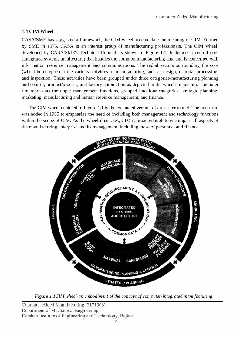
1.4 CIM Wheel
CASA/SME has suggested a framework, the CIM wheel, to elucidate the meaning of CIM. Formed
by SME in 1975, CASA is an interest group of manufacturing professionals. The CIM wheel,
developed by CASA/SME's Technical Council, is shown in Figure 1.1. It depicts a central core
(integrated systems architecture) that handles the common manufacturing data and is concerned with
information resource management and communications. The radial sectors surrounding the core
(wheel hub) represent the various activities of manufacturing, such as design, material processing,
and inspection. These activities have been grouped under three categories-manufacturing planning
and control, product/process, and factory automation-as depicted in the wheel's inner rim. The outer
rim represents the upper management functions, grouped into four categories: strategic planning,
marketing, manufacturing and human resource management, and finance.
The CIM wheel depicted in Figure 1.1 is the expanded version of an earlier model. The outer rim
was added in 1985 to emphasize the need of including both management and technology functions
within the scope of CIM. As the wheel illustrates, CIM is broad enough to encompass all aspects of
the manufacturing enterprise and its management, including those of personnel and finance.
Figure 1.1CIM wheel-an embodiment of the concept of computer-integrated manufacturing
Computer Aided Manufacturing
Computer Aided Manufacturing (2171903)
Department of Mechanical Engineering
Darshan Institute of Engineering and Technology, Rajkot
5
1.5 EVOLUTION OF CIM
CIM has been evolving since the mid-1970s; however, until 1980 it was merely a concept. The
1980s, especially the second half, saw CIM expand into a technology. By now, industry has realized
that CIM is a necessity rather than a luxury.
Computer-integrated manufacturing continues to evolve so that any claim that a "true" CIM
plant exists is debatable. Progress in this direction has been phenomenal, however, and several full-
blown CIM plants will probably be operating by the turn of the century. Today, numerous companies
market an array of products that, when put together intelligently, can convert an average
manufacturing facility into a CIM operation.
Primary factors that have led to the development of the CIM concept and associated
technologies include the following:
1. Development of numerical control (NC)
2. The advent and cost-effectiveness of computers
3. Manufacturing challenges, such as global competition, high labor cost, regulations, product
liability, and demand for quality products
4. The capability-to-cost attractiveness of microcomputers.
1.6 TYPE OF MANUFACTURING SYSTEMS
Manufacturing entails so many processes and operations that comprehending them requires some
type of categorization.
Manufacturing operations can be categorized in several ways depending on the purpose of
grouping, for example, national versus international or product types. For most purposes,
classifications reflect the following six criteria:
1. Continuous or discrete
2. Variety and volume
3. Raw material to final product
4. To order or to stock
5. Size
6. Machinery used
1.6.1 Continuous or Discrete Manufacturing
Manufacturing operations fall into two very broad groups: (a) continuous-flow or process type and
(b) discrete-parts manufacturing (also known as discrete manufacturing). Continuous-flow operations
typify the chemical and mining industries and oil refineries, which produce large amounts of bulk
material. Products in these groups are usually measured in units of volume or weight, batch size is
large, and product variety is low. Since batches are large, designing and building special machines
for their production make sense. Such machines are usually expensive, but their cost is distributed
over a large volume, contributing only marginally to the unit cost. Since processes are specialized,
they are difficult to modify or salvage, if for some reason the customer no longer requires the
product.

Computer Aided Manufacturing
Computer Aided Manufacturing (2171903)
Department of Mechanical Engineering
Darshan Institute of Engineering and Technology, Rajkot
6
Continuous-flow operations, used to manufacture "mature" products in large volumes, are
relatively easier to control and operate, since production uses dedicated machines. These operations
are usually fully automated, with operators minding the machines. From an integration point of view,
the production task is simpler, since processing requirements (one sequentially following the other)
are such that integration is built in at the equipment design stage itself. The need for flexibility is just
not there. As technology improves, newer machines with built-in automation replace the old ones.
Thus, while the term CIM may be new to process industries, integrated manufacturing based on the
CIM concept certainly is not.
The term discrete-parts manufacturing denotes operations involving products that can be
counted. The output of process-type industries is also counted eventually: for example, sugar in
terms of number of sacks or tons. What distinguishes discrete manufacturing from process industries
is the potential flexibility of its output. When demand falls in process industries, operations are
simply phased out. Discrete-type operations, on the other hand, are cost-effective to modify for other
products needed by the market.
A special feature of discrete manufacturing is that the end product, generally made of several
components, can be disassembled and reassembled; an example is a bicycle. It is not essential for the
end product to comprise several components. For example, a discrete manufacturing facility that
machines only connecting rods of different shapes and sizes for automobile manufacturers produces
a single-part end product. Whether single- or multiple-part, a product must be designed, raw materi-
als procured, machines set up, tools sharpened, operators trained, and a host of other steps taken
before actual production can begin. All this is, in essence, preparation for production. The
preparation-for-production cost is normally the same whether one unit or hundreds of units are
produced. Since it is independent of the number of units actually produced, this cost is fixed.
Obviously, the burden of the fixed cost on each unit grows as batch size (number of units in the
batch) declines. In mass production, where batch size is large, fixed cost per unit is obviously low.
At the other extreme, in job shops with a batch size of one or two, the fixed cost per unit is relatively
high.
1.6.2 Variety and Volume
Another way to look at manufacturing facilities is according to variety and volume. A low-variety,
high-volume operation is easier to manage, since dedicated automation is possible. A high-variety,
low-volume operation, on the other hand, is more difficult to operate and manage. Based on volume
and variety, discrete manufacturing is of three types:
Mass production
Batch production
Job shop
Mass Production. In mass production of discrete parts or assemblies-for example, bolts or ballpoint
pens-the production volume is high. Therefore, special purpose, dedicated equipment can be
employed. Machines are considered dedicated when they are tailored to specific products. Examples
of mass-produced goods include bicycles, washing machines, and video games. A mass-production
facility is termed a transfer line when products are assembled while conveyor systems transfer them

Computer Aided Manufacturing
Computer Aided Manufacturing (2171903)
Department of Mechanical Engineering
Darshan Institute of Engineering and Technology, Rajkot
7
from one end of the plant to the other. A good example of a transfer line is an automobile-production
facility.
Batch Production. In batch production of parts or assemblies, the volume is lower, and the variety
higher, than in mass production. When the end item is an assembled product, the producer may make
some parts in house and buy others from vendors. Batch production is sometimes referred to as a
midvolume, midvariety operation. The limited volume does not justify very specialized production
machines; general-purpose machines are used instead. This does not, however, alter the shop-floor
goal of keeping the machines running and the operators busy. An enormous amount of coordination
among various production functions is essential to optimize use of the resources. In this type of
application, CIM technologies such as cellular manufacturing or robotics hold promise to deliver the
economies of mass production while still coping with variety. Batch production, and to some extent
mass production, of discrete products provides all the challenges under CIM.
In batch production, goods are manufactured in batches that may be repeated as required. As Figure
1.2 shows, manufacturing directly contributes 30% to the GNP in industrialized economies. Batch
production accounts for 40% of this or 12% to the GNP. Also note that three-quarters of batch
production involves batch sizes of 50 or less. Thus, a typical manufacturing facility produces small
batches.
Figure 1.2 Importance of batch production and small batch sizes to GNP
Job Shop Production. The job shop represents the most versatile production facility. Within the
limitations of the machines and the operators, it can manufacture almost any product. With a low
production volume, sometimes as low as 1 to 10 units, the cost of product design and set up is
relatively high. Production facilities for aircraft, ships, or special machine tools are examples of job
shops. NC and CNC technologies can significantly improve the productivity of job shops.

Computer Aided Manufacturing
Computer Aided Manufacturing (2171903)
Department of Mechanical Engineering
Darshan Institute of Engineering and Technology, Rajkot
8
Which of the three discrete-manufacturing facilities is suitable for a product depends on two
factors: variety and volume. How many different products (including their models, if significantly
different) are to be produced? How many of each product (i.e., of each variety) is to be produced
during a given period of time? Note that the term volume actually means quantity-the number of
units. On the basis of volume and variety, the three types of manufacturing facilities just discussed
can be represented graphically as shown in Figure 1.3. The overlaps emphasize the fact that their
boundaries are not rigid. The actual values on the volume and variety axes depend on the complexity
of the product.
Figure 1.3 Volume and variety by production type
1.6.3 Raw Material to Final Product
On the basis of the relationship between raw material and the end product, manufacturing follows
one of four different patterns: disjunctive, sequential locational, or combinative.
Disjunctive. In the disjunctive pattern, a single raw material is progressively processed into its
various components as end products. Examples of disjunctive facilities are slaughterhouses, lumber
mills, and oil refineries.
Sequential. In sequential facilities, too, there is only one raw material as input. But, unlike
disjunctive operations, which separate the raw material into components, it is progressively modified
to become the end product. An example is a supplier's production facility that machines castings for
the automobile manufacturer.
Locational. Locational patterns involve buying, storing, and eventually distributing manufactured
goods without any substantial physical modification in the product. An example is the company that
buys a product in large quantities and distributes it in small packets under its own brand name. This
pattern suits bulk materials, such as sugar or rice.
Computer Aided Manufacturing
Computer Aided Manufacturing (2171903)
Department of Mechanical Engineering
Darshan Institute of Engineering and Technology, Rajkot
9
Combinative. The combinative type is basically discrete manufacturing in which components-some
produced in-house and some bought from suppliers-are assembled, inspected, packaged, and shipped
as end products. A good example is an automobile factory.
From a production viewpoint, the combinative pattern is the most, complex. CIM is targeted
primarily at this pattern, although CIM concepts apply to the other three as well.
1.6.4 To Order or to Stock
Based on the immediate destination of the end products, manufacturing may be of two types. In the
first, products are shipped directly to consumers, wholesalers, or retailers. Such companies are said
to produce "to order." Since they do not store the end products, for finished-goods inventory is
unnecessary. Capital is therefore released and profit realized immediately following production. Job
shops usually operate in this mode. In the second type, products are stocked in finished-goods
inventory; marketing distributes them to retailers or consumers as needed. This type of operation is
said to produce "to stock." Such facilities usually produce in batch sizes that minimize the unit cost.
In this type, capital is tied up until the end products can be sold.
CIM can offer significant benefits for both types of operations. To-order companies can
respond rapidly to meet the needs of consumers, while to-stock companies can produce economically
in smaller batch sizes, thus lowering thc capital investment in finished-goods inventory.
1.6.5 Size
It is sometimes convenient to classify manufacturing companies on the basis of size, with criteria
such as number of employees, annual sales turnover, net worth, and so forth.
Whether a company is small or large is often determined by the number of employees. While
there is no standard cut-off number, the following categorization is usually practiced: small, below
100; medium, 100 to 499; large, 500 or more.
Contrary to the general perception that only large companies can afford modern facilities, the
level of modernization and the sophistication of technology used are independent of the company
size.
1.6.6 Machinery Used
A variety of machine tools, equipment, and processes are used in an average plant. They fall into the
following functional groupings:
Metal forming
Metal cutting
Assembly
Material handling
Inspection, testing, gauging
Others, such as casting, welding, riveting, brazing, heat treatment, washing stations, plastic molding,
etc.
Computer Aided Manufacturing
Computer Aided Manufacturing (2171903)
Department of Mechanical Engineering
Darshan Institute of Engineering and Technology, Rajkot
10
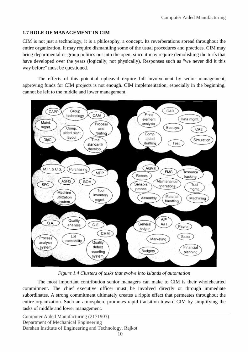
1.7 ROLE OF MANAGEMENT IN CIM
CIM is not just a technology, it is a philosophy, a concept. Its reverberations spread throughout the
entire organization. It may require dismantling some of the usual procedures and practices. CIM may
bring departmental or group politics out into the open, since it may require demolishing the turfs that
have developed over the years (logically, not physically). Responses such as "we never did it this
way before" must be questioned.
The effects of this potential upheaval require full involvement by senior management;
approving funds for CIM projects is not enough. CIM implementation, especially in the beginning,
cannot be left to the middle and lower management.
Figure 1.4 Clusters of tasks that evolve into islands of automation
The most important contribution senior managers can make to CIM is their wholehearted
commitment. The chief executive officer must be involved directly or through immediate
subordinates. A strong commitment ultimately creates a ripple effect that permeates throughout the
entire organization. Such an atmosphere promotes rapid transition toward CIM by simplifying the
tasks of middle and lower management.
Computer Aided Manufacturing
Computer Aided Manufacturing (2171903)
Department of Mechanical Engineering
Darshan Institute of Engineering and Technology, Rajkot
11
In an article appropriately entitled "Integrating Islands of Automation Is Management, Not
Technical Problem," Mehta (1987) identifies the following six tasks for the managers of CIM:
1. Develop a business model to understand the problem environment.
2. Develop a functional model for the processes, functions, and activities to describe both “as
is” and “to be”.
3. Develop an information model that identifies system interfaces, information exchange
patterns, database requirements, and applicable technologies.
4. Develop a network model to identify communication and networking requirements.
5. Develop an organizational model to investigate the implications of integrating the various
islands of automation (Figure 1.4) on the existing organization structure and culture, and how
to safeguard against detrimental effects.
6. Finally, develop the implementation plan which should take into account special features of
the business and operations.
1.8 EXPERT SYSTEMS
CIM decisions are more demanding than most decisions managers must make. Computers can help
simplify decision making, however. Besides their conventional use in processing information,
computers can, with the help of expert systems, serve as "advisors" to management.
An expert system is basically a computer program designed to emulate an expert-hence the
name expert system. Expert systems apply facts stored in the computer and rules of thumb to help
users solve decision-making problems. In its simplest form, an expert system consists of a
knowledge base and an inference engine. The knowledge base is filled with facts and rules of thumb
a human expert would use. The inference engine comprises the techniques of retrieving and using
this knowledge.
Expert systems enable the users to capture the knowledge of experts in a series of statements,
for example: "When condition P exists, I do Q." Once expertise has been stored in the computer, the
system can help users solve problems in that area by suggesting likely outcomes or actions for a
given set of conditions. The knowledge base can be created in two ways:
1. A set of IF-THEN-ELSE rules can be entered, in which case the expert system is called a
rule-based system.
2. The program can contain a series of CONDITION-RESULT combinations. Such systems are
useful in finding patterns in a set of data, for example in machine diagnostics to relate
symptoms with causes. The knowledge is manipulated either by backward chaining or
forward chaining. Also called goal-driven, backward chaining works with the given results to
determine the likely initial conditions. The forward chaining starts with the given conditions
to predict the possible results by going through the decision tree. A decision tree is a list of all
possible options in making a decision; it resembles a tree with trunk and branches.
Computer Aided Manufacturing
Computer Aided Manufacturing (2171903)
Department of Mechanical Engineering
Darshan Institute of Engineering and Technology, Rajkot
12
In most cases, expert systems are developed by the users themselves, resulting in powerful tools
called shells. Like other software, modern expert systems are also user-friendly. As an example, one
system can translate the user request "Show me the names and salaries of employees in the quality
control department who got a raise in 1994" into a format it understands: SELECT name salary
FROM employee WHERE department QC (quality control) AND raise 1994.
1.9 PARTICIPATIVE MANAGEMENT
Largely due to its success in Japan, companies have begun to encourage all employees to participate
in managing the resources. New practices under this trend are collectively termed participative
management. Participative management theoretically generates team spirit for the benefit of the
company. Team spirit has been found to be effective only in smaller companies, however. Firms with
more than 150 employees are too large to function like a team.
According to Beaumariage and Shunk (1991), a teamwork approach involves the following issues:
1. Defining Teamwork
Definition of a Team
Characteristics of Teams
Notion of Empowerment
2. Organizational Considerations
Company Issues
Culture Shift
3. Employee Issues
Management Input
Team Participant Considerations
4. Mechanics of Teamwork
Forming Teams
The Rebel
Rewarding Teamwork
1.10 IMPACT OF CIM ON PERSONNEL
Computer-integrated manufacturing and its building blocks such as CAD or CNC affect all company
personnel, from operators to the CEO and president. Early predictions that only unskilled workers
would be affected have been proven wrong. The restructuring and downsizing of a company reduce
middle management positions as well. Employees in the 40-to-50 age group are being asked to retire,
and those younger are being asked to retrain.
Harrington (1985) identified some of the changing skills of people working in CIM
environments. For example, operators of NC machines need additional skills in part programming
and CNC technology. Jobs of expediters are being eliminated altogether. Reading inspection
instruments is less demanding since they have digital readouts and can print out the inspection
results. As another example, cost estimating has been computerized to the point that anyone with
keyboarding skills and some training can carry out this function.

Computer Aided Manufacturing
Computer Aided Manufacturing (2171903)
Department of Mechanical Engineering
Darshan Institute of Engineering and Technology, Rajkot
13
Even areas that normally require higher skills have changed. For example, a designer's
creativity and skills are challenged by CAD workstations that instantly test their ideas on design
improvement. Knowledge-based software systems can even assess the quality of the designer's
creativity by evaluating the manufacturability of an idea. Moreover, in CIM, designers need to know
more about manufacturing, for example, part programs not just for machining but also for assembly,
CMM inspection, or robotized packaging.
Most of all, management may need to undergo a cultural change. To begin, the president and
CEO must believe in CIM. Their primary task is convincing other board members of CIM's leverage.
Since CIM affects all three functions of management-planning, implementation, and control-change
is required throughout the organization. Managers must switch from hard copy reports to electronic
mail. The real-time environment under CIM demands faster turnarounds on decision making, which
becomes a group activity. Meetings may be sudden, short, and highly focused, since the input
information for the meeting will be clear, concise, and current.
CIM demands that specialists understand functions outside their areas. Specialists need to
generalize more, and generalists need to specialize more. Under CIM, jack-of-all-trades but master of
none will give way to jack-of-all-trades and master of some. This may initially be difficult, but
knowledge-based computer systems smooth the transition by providing a helping hand.
Thus, the skills and practices of the past undergo profound change with CIM. As Harrington
(1985) explains: "Indeed, it is safe to say that the impact of computer integrated manufacturing will
be greater on the people involved than on the technology itself". The transition from conventional
practices to those required under CIM benefits from training and retraining of the people affected.
1.11 ROLE OF MANUFACTURING ENGINEERS
In CIM environments, manufacturing engineers interact very closely with designers. They need to
understand design, especially CAD, and the design process. CAD requires them to have insight into
the principles of computer technology and the associated terminologies such as bits and bytes, RAMs
and ROMs. The same is true for first-line supervisors or foremen who interact with operators,
management, and plant equipment. Maintenance staff need to work more as a team with a common
pool of expertise in areas as diverse as electronics, computers, hydraulics, pneumatics, and the usual
mechanical and electrical systems.
Commissioned by the SME, A. T. Kearney Inc. conducted a survey to predict the job
descriptions of manufacturing engineers by the year 2000. Entitled "Countdown to the Future: the
Manufacturing Engineer in the 21st Century" and known as Profile 21, the survey results are based
on the opinions of 7,500 manufacturing practitioners, a series of roundtable discussions, a Delphi
study, a chief executive officer questionnaire, and an extensive literature search. It predicts that the
environment in which future manufacturing engineers will operate will change due to:

Computer Aided Manufacturing
Computer Aided Manufacturing (2171903)
Department of Mechanical Engineering
Darshan Institute of Engineering and Technology, Rajkot
14
1.12 MEANING OF CAM
Computer-aided manufacturing (CAM) is an application technology that uses computer software and
machinery to facilitate and automate manufacturing processes. CAM is the successor of computer-
aided engineering (CAE) and is often used in tandem with computer-aided design (CAD).
Computer-aided manufacturing (CAM) is the use of software to control machine tools and related
ones in the manufacturing of work-pieces. This is not the only definition for CAM, but it is the most
common, CAM may also refer to the use of a computer to assist in all operations of a manufacturing
plant, including planning, management, transportation and storage. Its primary purpose is to create a
faster production process and components and tooling with more precise dimensions and material
consistency, which in some cases, uses only the required amount of raw material (thus minimizing
waste), while simultaneously reducing energy consumption. CAM is now a system used in schools
and lower educational purposes. CAM is a subsequent computer-aided process after computer-aided
design (CAD) and sometimes computer-aided engineering (CAE), as the model generated in CAD
and verified in CAE can be input into CAM software, which then controls the machine tool. CAM is
used in many schools alongside Computer Aided Design (CAD) to create objects.
1.13 OBJECTIVE OF CAM
The use of computers to guide the working of the industrial processes is known as computer aided
manufacturing or CAM. Any factory can be made highly automated by deploying real time systems
and robotics. A CAM system is highly efficient because it can control the production house through
different automated techniques. The purpose of CAM is to ensure that the error rate is decreased,
uniformity of products is high and precision in the processes can be achieved. CAM operations is
part of now almost all industries. It is helpful in removing errors from the primary manufacturing
processes and can also keep track of further orders and material to be used. The automated plants
have provided a hygiene and clean environment to various processes which cannot be achieved fully
by manual processes. For example, the packaging of meat and related products is fully done by
automated plants from the slaughter of the animal to the final product. This has also reduced the
labor cost and other operating overheads. The processes are now fully automated that they can
replace the tools and switch to the successive processes on their own.
1.14 SCOPE OF CAM
Integrated CAD/CAM/CAE Software like Pro/Engineer, I-DEAS & CATIA help manufacturers
optimize product concept early in Design process, enabling them to significantly improve product
quality, while reducing product development time and cost. Moreover people having 3D
CAD/CAM/CAE knowledge have better chances of growth, immediate employability after
completion of course, graduation and chances of jobs abroad.
As the market economy opens more and more it has become extremely competitive and with this
state of economy, skilled people play the most important role in organization. Hence it becomes
imperative on the part of top Tool Room Training centers and engineering. Colleges to especially
Computer Aided Manufacturing
Computer Aided Manufacturing (2171903)
Department of Mechanical Engineering
Darshan Institute of Engineering and Technology, Rajkot
15
look for new initiatives towards improving the skills and knowledge of students. An emerging trend
of engineering. Education in Tool Room and the world is the rapid incrementation of
CAD/CAM/CAE software as an essential part of curriculum.
1.15 ROLE OF MANAGEMENT IN CAM
In the modern world, rapid changes and global expansion results in the changing of business
organizational trend. Business transactions that had been done traditionally are no longer sufficient,
so a new method has to be introduced to meet the consumers’ to cope with current market demands,
therefore Business Process Reengineering (BPR) that has been introduced since the 1990s are used
worldwide nowadays, with the addition of information system and technology. IT can help to
improve main business processes in terms of communication, inventory management, data
management, management information systems, customer relationship management (CRM),
computer-aided design (CAD), computer-aided manufacturing (CAM) and computer-aided
engineering (CAE). This study explained the role of IT in a business’s process within area of CRM,
communication, information management and inventory management to boots efficiency and
effectivity a BPR adoptions.
REFERENCES:
S. Kant Vajpayee “Principles of Computer-Integrated Manufacturing” Prentice Hall of
India Private Limited.

NC/CNC Machine
Computer Integrated Manufacturing (171903)
Department of Mechanical Engineering
Darshan Institute of Engineering and Technology, Rajkot
1
EXPERIMENT NO. 2
AIM: To study about CNC & it’s programming.
2.1 NC CONTROLS
Numerical control (NC) is the technique of giving instructions to a machine in the form of a code
which consists of numbers, letters of the alphabet, punctuation marks and certain other symbols.
Controlling a machine tool by means of a prepared program is known as numerical control.
NC equipment has been defined by the Electronic Industries Association (EIA) as:
“A system in which actions are controlled by the direct insertion of numerical data at some
point. The system must automatically interpret at least some portion of this data".
Instructions are supplied to the machine as blocks of information. A block of information
commands sufficient to enable the machine to carry out one individual machining operation. Each
block is given a sequence number for identification.
A set of instructions forms an NC program. When the instructions are organized in a logical
manner they direct the machine tool to carry out a specific task. It is thus termed as part program.
In a typical NC system, the numerical data which is required for producing a part is
maintained on a punched tape and is called the part program. The part program is arranged in the
form of blocks of information, where each block contains the numerical data required to produce one
segment of the work piece. The punched tape is moved forward by one block each time the cutting of
a segment is completed.
Preparing the part program for a NC machine tool requires a part programmer. The part
programmer must possess knowledge and experience of tools, cutting fluids, machinability data and
fixture design techniques.
Part programmers must be familiar with the function of NC machine tools and machining
processes and have to decide on the optimal sequence of operations. Part programs are written
manually or by using a computer-aided language, such as automated program tool (APT).
2.2 TYPES OF CNC
Computer numerical control is applied to a variety of machines. Most of these find ready application
in aircraft, automobile and general engineering industry. Some of them are listed below:
1. Machining Centre
• Horizontal
• Vertical
• Universal
NC/CNC Machine
Computer Integrated Manufacturing (171903)
Department of Mechanical Engineering
Darshan Institute of Engineering and Technology, Rajkot
2
2. CNC Turning Centres
3. CNC Milling/Drilling Machines, Plane Milling Machines
4. Gear Hobbing Machines
5. Gear Shaping Machines
6. Wire Cut EDM/EDM
7. Tube Bending
8. Electron Beam Welding
9. Laser/Arc/Plasma Cutting
10. Co-ordinate Measuring Machines
11. Grinding Machines
• Surface Grinder
• Cylindrical Grinder
• Centreless Grinder
12. Tool and Cutter Grinder
13. CNC Boring and Jig Boring Machines
14. Press Brakes
15. CNC Transfer Lines, SPM's
16. Electrochemical Milling Machines
17. Abrasive Water Jet Cutting Machines
18. Flow Forming Machines
19. Roll Forming Machines
20. Turret Punch Press
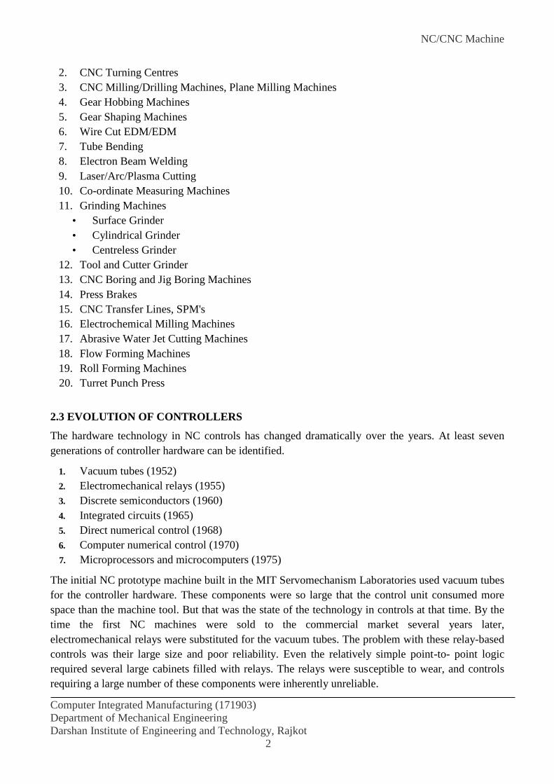
2.3 EVOLUTION OF CONTROLLERS
The hardware technology in NC controls has changed dramatically over the years. At least seven
generations of controller hardware can be identified.
1. Vacuum tubes (1952)
2. Electromechanical relays (1955)
3. Discrete semiconductors (1960)
4. Integrated circuits (1965)
5. Direct numerical control (1968)
6. Computer numerical control (1970)
7. Microprocessors and microcomputers (1975)
The initial NC prototype machine built in the MIT Servomechanism Laboratories used vacuum tubes
for the controller hardware. These components were so large that the control unit consumed more
space than the machine tool. But that was the state of the technology in controls at that time. By the
time the first NC machines were sold to the commercial market several years later,
electromechanical relays were substituted for the vacuum tubes. The problem with these relay-based
controls was their large size and poor reliability. Even the relatively simple point-to- point logic
required several large cabinets filled with relays. The relays were susceptible to wear, and controls
requiring a large number of these components were inherently unreliable.
NC/CNC Machine
Computer Integrated Manufacturing (171903)
Department of Mechanical Engineering
Darshan Institute of Engineering and Technology, Rajkot
3
The use of transistors based on discrete semiconductor technology formed the next generation
of NC controllers. The use of transistors helped to reduce the number of electromechanical relays
required. Accordingly, this increased the reliability because the use of transistors avoided the wear
problem. It also contributed to a downsizing of the controller cabinet and allowed systems designers
to build more complex circuitry into the NC controller. Features such as circular interpolation
became practical with these controls.
Size and reliability still remained as problems with NC controls which used discrete
semiconductors. Also, the electronics were sensitive to heat, and fans or air conditioners were
required in the cabinets to operate under factory conditions.
Around 1965, integrated circuits were introduced for use in NC controls. This type of
electronic hardware brought significant improvements in size and reliability. The number of separate
components could be reduced by 90%. There were corresponding savings in cost to the user. The
trend toward LSI (large-scale integrated) circuits has allowed more control features to be packaged
into smaller control cabinets. Among these features are circular and hyperbolic interpolation
routines, inch-to-metric conversions, and vector feedrate computations.
The next development in NC control marked the introduction of digital computers in NC
controller technology. This constituted a fundamental change in NC evolution. All of the previous
controls were made up of hard-wired components. The functions that were performed by these
control systems could not be easily changed, due to the fixed nature of the hard-wired design. Digital
computers, on the other hand, are based on a different approach. In this new approach, the control
functions were programmed into the computer memory and could be changed by altering the
program.
DNC was the first of the computer control systems to be introduced, around 1968. In the
evolution of computer technology, the computers of that era were quite large and expensive, and the
only feasible approach seemed to be to use one large computer to control a number of machine tools
on a time-shared basis. The advantage of DNC was that it established a direct control link between
the computer and the machine tool, hence eliminating the necessity for using punched tape input.
The tape and tape reader were turning out to be the least reliable components in the conventional NC
systems.
With the recognized trend toward smaller, less expensive computers, it soon became practical
to apply a single small computer to one machine tool. This concept came to be called computer
numerical control (CNC). The CNC systems were first commercially introduced around 1970, and
they applied the soft-wired controller approach to good advantage. One standard computer control
unit could be adapted to various types of machine tools by programming the control functions into
the computer memory for that particular machine. Today, because of the advantages of CNC, very
few conventional hard-wired NC systems are sold in the United States.
Advances in computer technology have continued to provide smaller and smaller digital
control devices which have greater speed and capacity at lower cost. This has permitted the machine
tool builders to design the CNC control panel as an integral part of the machine tool rather than as a

NC/CNC Machine
Computer Integrated Manufacturing (171903)
Department of Mechanical Engineering
Darshan Institute of Engineering and Technology, Rajkot
4
separate stand-alone cabinet. This reduces floor space requirements for the machine. The VLSI (very
large scale integrated) circuits used in these controllers are advantageous to the machine tool
designer and to the machine user. Fewer components in the controller means it is easier and less
expensive for the machine tool builder to fabricate. Fewer circuit boards, which are readily replaced,
reduce the burden on the user for maintenance and repair.
2.4 COMPONENTS OF NC/CNC SYSTEM
Following are the basic components of an operational numerical control system:
(i) Programme of instructions
(ii) Controller Unit also called Machine Control Unit (MCU)
(iii) Machine tool or other controlled equipment
2.4.1 PROGRAMME OF INSTRUCTIONS
The programme of instructions is the detailed step by step set of directions which tell the machine
tool what to do and in what sequence. The part programme is written in coded form and contains all
the information needed for machining the component. The part programme is fed to the machine
control unit through some input medium. Various types of input media are:
(a) Punched cards
(b) Magnetic tapes and floppy disks
(c) Paper tape
Punched Cards
Figure 2.1 Representation of alphabetic and numerical information on a computer card

NC/CNC Machine
Computer Integrated Manufacturing (171903)
Department of Mechanical Engineering
Darshan Institute of Engineering and Technology, Rajkot
5
Punched cards were once widely used as a medium for data input in all numerical control systems. A
typical punched card used in IBM systems has 80 columns and each 'column has numbers which
identify the punching position. There are 12 punch positions or rows in each card designated as 12,
11 and 0 to 9. For any numeric and alphabet to be punched on the card, a code is used and
rectangular blocks are punched on the card at one or more places. Normally, one card is used for
encoding each instruction or for storing each master record. However, if the instruction data is too
large to fit on one card, a set of two or more cards may be used. A punched card with the hole
corresponding to all the characters and numbers is shown in Figure 2.1.
Magnetic Tape and Disk
Magnetic tapes and disks are widely used for data storage as well as data input to NC systems. The
data is stored in the coded form by means of magnetised spots on magnetic medium in both cases.
The magnetic tapes and magnetic disks are re-usable media. The data once stored can be erased and
new data saved on the magnetic tape or disk. Magnetic tape used in numerical control systems is
identical to the tape used in common home tape recorder. The width of the tape is 6 mm or 25 mm.
Magnetic disks or floppy disks are circular disks and consist of a material which can be magnetised.
The disk is enclosed in a square protective sleeve. The data is stored in concentric tracks arranged on
the surface of the disk. The commonly used sizes of magnetic disks are 5.25 inch diameter and 3.5
inch diameter. The magnetic disk is a random access device which means that any piece of data
recorded on the disk can be accessed at random. The data transfer rate in case of magnetic disks is
much faster than magnetic tape. The magnetic tapes and disks can store more data compared to other
input media. But the data stored on magnetic tapes and disks can be corrupted if these are brought
into magnetic fields.
Punched Tape
Figure 2.2 25 mm wide punched card
NC/CNC Machine
Computer Integrated Manufacturing (171903)
Department of Mechanical Engineering
Darshan Institute of Engineering and Technology, Rajkot
6
Punched tape is widely used for feeding the programme to numerical control systems. There are
various types of paper tapes used in NC system but the standard format for tape size and
configuration, issued by Electronic Industries Association of USA (EIA) and International Standards
Organisation (ISO), are universally accepted. A standard tape is 25 mm wide. The punched tape has
capacity for storing 10 characters per 25 mm length. A punched tape is shown in Figure 2.2. There
are 8 tracks on the tape, which are used for punching the information in coded form. The edge
adjacent to track 1 is called reference edge. A row of small holes between track 3 and track 4 is used
for feeding the tape into the tape reader. The information required to machine the component is
punched on the tape by a tape punching device.
2.4.2 MACHINE CONTROL UNIT
The second basic component of the NC system is the controller unit. This consists of the electronics
and hardware that read and interpret the program of instructions and convert it into mechanical
actions of the machine tool. The typical elements of a conventional NC controller unit are discussed
below.
Programme Reader
Programme reader is a device used to read the coded instructions from the programme of
instructions. Programme readers are classified on the basis of programme input medium as:
(a) Card Readers
Card readers are those devices which read the information punched into a card, converting the
presence or absence of a hole into an electric signal representing a binary 0 or 1. The punched cards
are placed into a hopper and when the command to read is given, a lever pushes a card from the
bottom of stack. Generally, the card is moved lengthwise over a row of 80 reed brushes. These
brushes read the information punched along the bottom row of the card. If a hole is punched in a
particular row, a brush makes electrical contact through the hole in the card generating a signal
which is used by the computer. The next row is then read, and this process continues until all rows
have been read, after which the next card is moved into position on the brushes. Faster card readers
use photoelectric cells under the 12 punch positions along a column and an illuminating source
above the card. As each column on the card is passed over the 12 photoelectric cells, whether or not
a given position is punched is determined by the presence or absence of electric signal from the
corresponding photocell. Card readers operate at speeds ranging from 12 to 1000 cards per minute.
(b) Punched Tape Readers
When a punched tape is passed through a punched-tape reader, electric connections are either close
or open depending on whether there is a hole punched at a particular track or not. The coded
instructions on the tape are transformed into their electrical analogues which are utilized for
controlling the various machine tool functions. The punched tape readers commonly used are:
(i) Mechanical (Electro-mechanical)
(ii) Photo electrical
(iii) Pneumatic
NC/CNC Machine
Computer Integrated Manufacturing (171903)
Department of Mechanical Engineering
Darshan Institute of Engineering and Technology, Rajkot
7
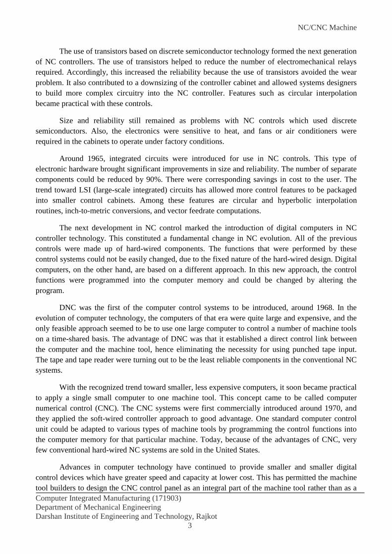
(i) Mechanical Tape Reader
Figure 2.3 Principle of the mechanical tape reader
The principle of a simple mechanical device for reading the punched tape is shown in Figure 2.3. If
there is no hole in the tape the contacts remain open but when a hole is present in the tape, its
presence is detected by a probe and bending of flexible strip causes the contacts to close. The
presence of holes in the tape causes the switches to close. The switch is in ON position (hole) or OFF
position (no hole) accordingly.
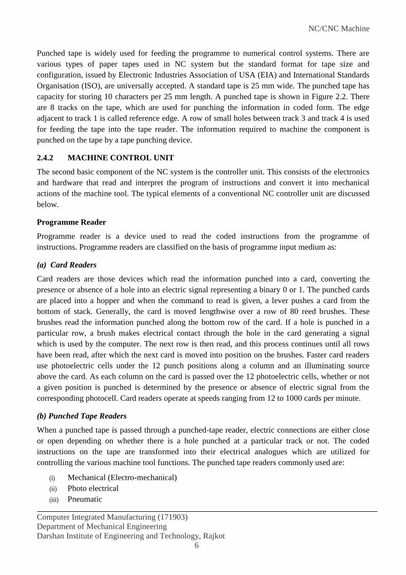
(ii) Optical or Photo-electrical Reader
Figure 2.4 Principle of the optical tape reader
The operation of an optical photo electric tape reader is based upon the principle that if a beam of
light falls on a photoelectric cell, the latter generates an electric signal. The schematic diagram of a
photoelectric tape reader is shown in Figure 2.4. The punched tape is fed between a light source and
a series of photo-cells. Whenever a hole is present in the tape, light from the light source passes
through the hole and energises the corresponding photo-cell which converts the light energy into
electrical energy to produce a pulse i.e. ON position. The pulse is amplified and processed into a
form suited to the control circuit. When there is no hole, the light from the light source does not
reach the photo-cell, hence no signal is produced and the position is recorded as OFF.
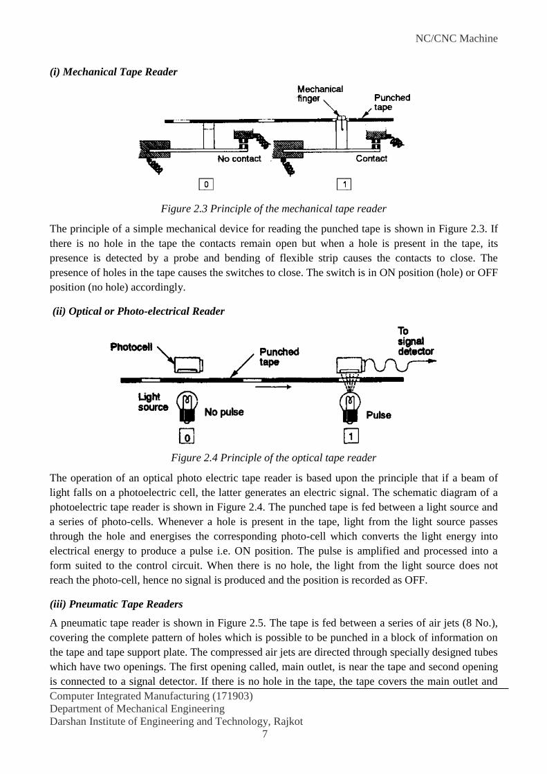
(iii) Pneumatic Tape Readers
A pneumatic tape reader is shown in Figure 2.5. The tape is fed between a series of air jets (8 No.),
covering the complete pattern of holes which is possible to be punched in a block of information on
the tape and tape support plate. The compressed air jets are directed through specially designed tubes
which have two openings. The first opening called, main outlet, is near the tape and second opening
is connected to a signal detector. If there is no hole in the tape, the tape covers the main outlet and
NC/CNC Machine
Computer Integrated Manufacturing (171903)
Department of Mechanical Engineering
Darshan Institute of Engineering and Technology, Rajkot
8
the free escape of air is restriced and a back pressure is developed in the supply tube. This back
pressure is sensed by the signal detector and position is recorded as '0' i.e. OFF. But if a punched
hole in the tape comes in front of the main outlet, the air is allowed to escape freely and no back
pressure is built up in the supply tube. This loss of back pressure is detected by the signal detector
and position is recorded as '1' i.e. ON. The support plate prevents the tape from being blown away by
the compressed air coming from main outlet.
Figure 2.5 Principle of the pneumatic tape reader
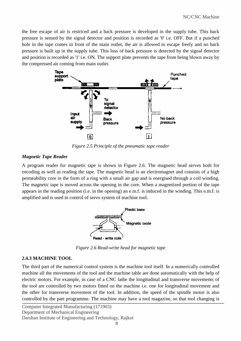
Magnetic Tape Reader
A program reader for magnetic tape is shown in Figure 2.6. The magnetic head serves both for
encoding as well as reading the tape. The magnetic head is an electromagnet and consists of a high
permeability core in the form of a ring with a small air gap and is energised through a coil winding.
The magnetic tape is moved across the opening in the core. When a magnetized portion of the tape
appears in the reading position (i.e. in the opening) an e.m.f. is induced in the winding. This e.m.f. is
amplified and is used in control of servo system of machine tool.
Figure 2.6 Read-write head for magnetic tape
2.4.3 MACHINE TOOL
The third part of the numerical control system is the machine tool itself. In a numerically controlled
machine all the movements of the tool and the machine table are done automatically with the help of
electric motors. For example, in case of a CNC lathe the longitudinal and transverse movements of
the tool are controlled by two motors fitted on the machine i.e. one for longitudinal movement and
the other for transverse movement of the tool. In addition, the speed of the spindle motor is also
controlled by the part programme. The machine may have a tool magazine, so that tool changing is

NC/CNC Machine
Computer Integrated Manufacturing (171903)
Department of Mechanical Engineering
Darshan Institute of Engineering and Technology, Rajkot
9
done automatically. Also the other functions like machine ON/OFF, coolant ON/OFF, etc are
controlled through the part programme. The motors used for controlling the speed, feed and depth of
cut are either servomotors or stepper motors which enable the user to select any desired speeds and
feeds.
2.5 CLASSIFICATION OF NC SYSTEMS
The classification of NC machine tool systems can be done in three ways:
According to the type of machine: Point-to-point, straight-cut and continuous path
According to the programming method: Absolute and incremental
According to the type of control system: Open-loop and closed-loop
Point-to-Point
Point-to-point machines move only in straight lines. They are limited to drilling, reaming, boring,
etc. and straight milling cuts parallel to a machine axis. When making an axis move, all affected
drive motors run at the same speed. When one axis motor has moved the instructed amount, it stops
while the other motor continues until its axis has reached its programmed location. The point-to-
point positioning NC system is illustrated in Figure 2.7.
Figure 2.7 Point-to-point (positioning) NC system
The simplest example of a point-to-point (PTP) NC machine tool is a drilling machine. In a
drilling machine, the work piece is moved along the axes of motion until the centre of the hole to be
drilled is exactly beneath the drill. Then the drill is automatically moved towards the work piece, the
hole is drilled and the drill moves out in a rapid traverse feed. The work piece moves to a new point
and the above sequence of actions are repeated.
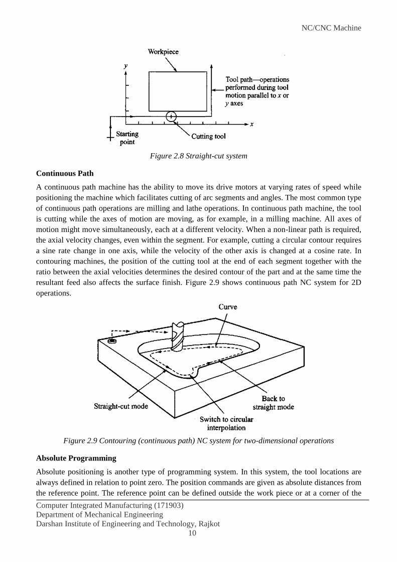
Straight-cut NC
Straight-cut control systems are capable of moving the cutting tool parallel to one of the major axes
at a controlled rate suitable for machining. It is, therefore, appropriate for performing milling
operation to fabricate work pieces of rectangular configurations. With this type of NC system it is
not possible to combine movements in more than a single axis direction. Therefore, angular cuts on
the work piece would not be possible. An example of straight-cut operation is shown in Figure 2.8.
An NC machine capable of straight-cut movements is also capable of PTP movement.
NC/CNC Machine
Computer Integrated Manufacturing (171903)
Department of Mechanical Engineering
Darshan Institute of Engineering and Technology, Rajkot
10
Figure 2.8 Straight-cut system
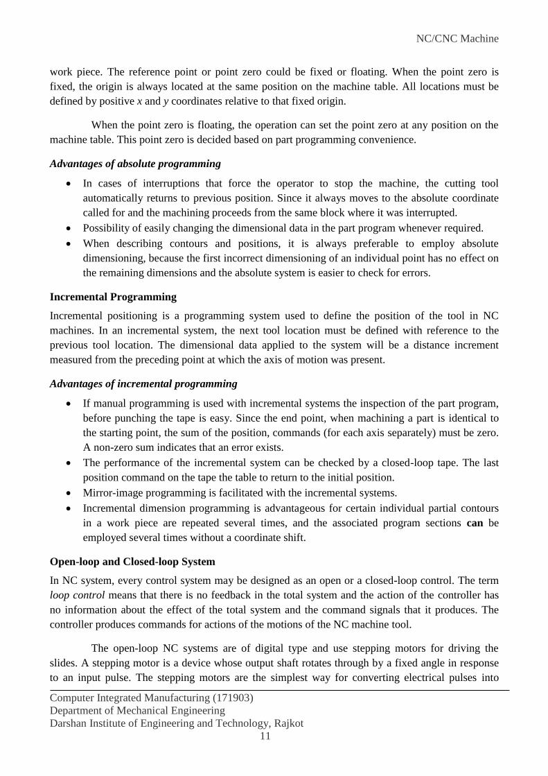
Continuous Path
A continuous path machine has the ability to move its drive motors at varying rates of speed while
positioning the machine which facilitates cutting of arc segments and angles. The most common type
of continuous path operations are milling and lathe operations. In continuous path machine, the tool
is cutting while the axes of motion are moving, as for example, in a milling machine. All axes of
motion might move simultaneously, each at a different velocity. When a non-linear path is required,
the axial velocity changes, even within the segment. For example, cutting a circular contour requires
a sine rate change in one axis, while the velocity of the other axis is changed at a cosine rate. In
contouring machines, the position of the cutting tool at the end of each segment together with the
ratio between the axial velocities determines the desired contour of the part and at the same time the
resultant feed also affects the surface finish. Figure 2.9 shows continuous path NC system for 2D
operations.
Figure 2.9 Contouring (continuous path) NC system for two-dimensional operations
Absolute Programming
Absolute positioning is another type of programming system. In this system, the tool locations are
always defined in relation to point zero. The position commands are given as absolute distances from
the reference point. The reference point can be defined outside the work piece or at a corner of the
NC/CNC Machine
Computer Integrated Manufacturing (171903)
Department of Mechanical Engineering
Darshan Institute of Engineering and Technology, Rajkot
11
work piece. The reference point or point zero could be fixed or floating. When the point zero is
fixed, the origin is always located at the same position on the machine table. All locations must be
defined by positive x and y coordinates relative to that fixed origin.
When the point zero is floating, the operation can set the point zero at any position on the
machine table. This point zero is decided based on part programming convenience.
Advantages of absolute programming
In cases of interruptions that force the operator to stop the machine, the cutting tool
automatically returns to previous position. Since it always moves to the absolute coordinate
called for and the machining proceeds from the same block where it was interrupted.
Possibility of easily changing the dimensional data in the part program whenever required.
When describing contours and positions, it is always preferable to employ absolute
dimensioning, because the first incorrect dimensioning of an individual point has no effect on
the remaining dimensions and the absolute system is easier to check for errors.
Incremental Programming
Incremental positioning is a programming system used to define the position of the tool in NC
machines. In an incremental system, the next tool location must be defined with reference to the
previous tool location. The dimensional data applied to the system will be a distance increment
measured from the preceding point at which the axis of motion was present.
Advantages of incremental programming
If manual programming is used with incremental systems the inspection of the part program,
before punching the tape is easy. Since the end point, when machining a part is identical to
the starting point, the sum of the position, commands (for each axis separately) must be zero.
A non-zero sum indicates that an error exists.
The performance of the incremental system can be checked by a closed-loop tape. The last
position command on the tape the table to return to the initial position.
Mirror-image programming is facilitated with the incremental systems.
Incremental dimension programming is advantageous for certain individual partial contours
in a work piece are repeated several times, and the associated program sections can be
employed several times without a coordinate shift.
Open-loop and Closed-loop System
In NC system, every control system may be designed as an open or a closed-loop control. The term
loop control means that there is no feedback in the total system and the action of the controller has
no information about the effect of the total system and the command signals that it produces. The
controller produces commands for actions of the motions of the NC machine tool.
The open-loop NC systems are of digital type and use stepping motors for driving the
slides. A stepping motor is a device whose output shaft rotates through by a fixed angle in response
to an input pulse. The stepping motors are the simplest way for converting electrical pulses into
NC/CNC Machine
Computer Integrated Manufacturing (171903)
Department of Mechanical Engineering
Darshan Institute of Engineering and Technology, Rajkot
12
proportional movement. Each pulse drives the stepping motor by a fraction of one revolution called
the step angle. Since there is no feedback from the slide position, the system accuracy is solely
dependent on the ability of the motor and accuracy of the mechanical parts.
The closed-loop control measures the actual position and velocity of the axis and compares
them with the help of a comparator. The comparator is a device that compares the output signal with
the signal received from the feedback device. The difference between the actual and the desired
values is the error. The control system is designed in such a way as to eliminate or reduce to a
minimum, the error, namely the system is of a negative feedback type.
In NC system both the input to the control loop and the feedback signals may be a sequence
of pulses. Each pulse representing one BLU, i.e., 0.01 mm. The digital comparator correlates the two
sequences and gives, by means of a digital-to-analog converter (DAC), a signal representing the
position error of the system and the output of DC drives the DC motor. A closed loop system uses
position sensors attached to the machine table to measure its position relative to the input value for
the axis.
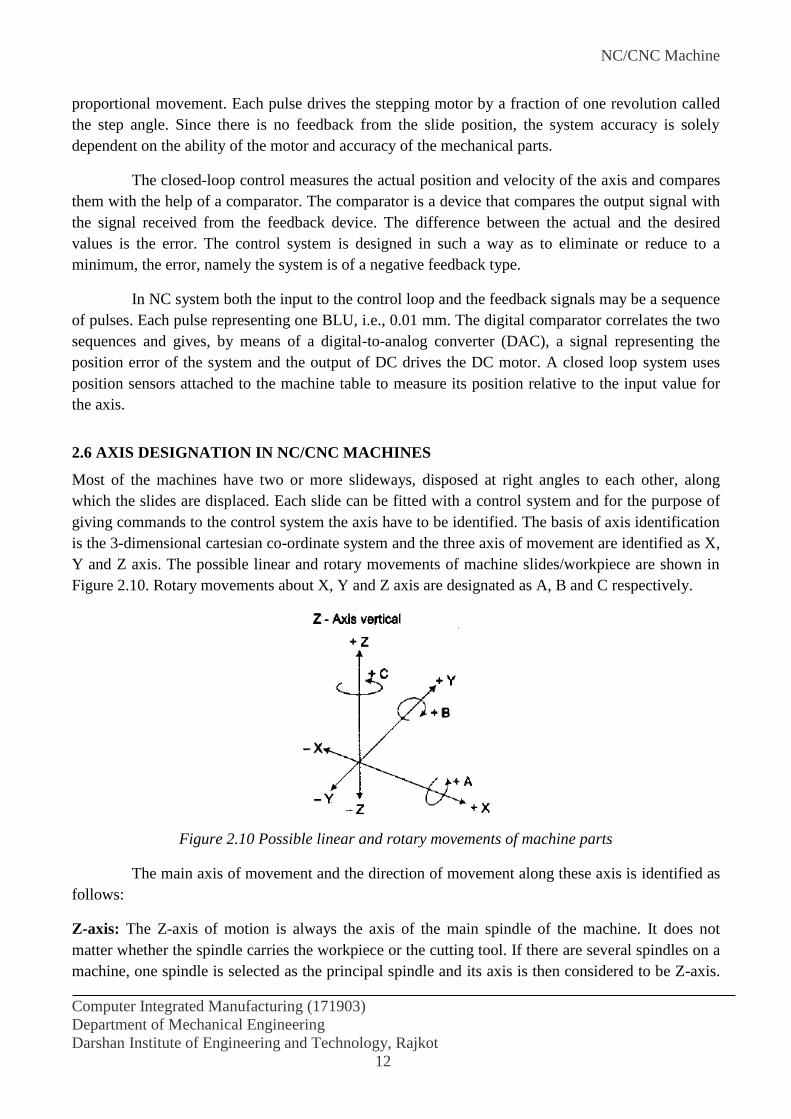
2.6 AXIS DESIGNATION IN NC/CNC MACHINES
Most of the machines have two or more slideways, disposed at right angles to each other, along
which the slides are displaced. Each slide can be fitted with a control system and for the purpose of
giving commands to the control system the axis have to be identified. The basis of axis identification
is the 3-dimensional cartesian co-ordinate system and the three axis of movement are identified as X,
Y and Z axis. The possible linear and rotary movements of machine slides/workpiece are shown in
Figure 2.10. Rotary movements about X, Y and Z axis are designated as A, B and C respectively.
Figure 2.10 Possible linear and rotary movements of machine parts
The main axis of movement and the direction of movement along these axis is identified as
follows:
Z-axis: The Z-axis of motion is always the axis of the main spindle of the machine. It does not
matter whether the spindle carries the workpiece or the cutting tool. If there are several spindles on a
machine, one spindle is selected as the principal spindle and its axis is then considered to be Z-axis.

NC/CNC Machine
Computer Integrated Manufacturing (171903)
Department of Mechanical Engineering
Darshan Institute of Engineering and Technology, Rajkot
13
On vertical machining centres, the Z-axis is vertical and on horizontal machining centres and turning
centres, the Z-axis is horizontal. Positive Z movement (+ Z) is in the direction that increases the
distance between the workpiece and the tool. Convention of designating the Z-axis on milling,
drilling and turning machines is shown in Figure 2.11.
X-axis: The X-axis is always horizontal and is always parallel to the work holding surface. If the Z-
axis is vertical, as in vertical milling machine, positive X-axis (+X) movement is identified as being
to the right, when looking from the spindle towards its supporting column.
If Z-axis is also horizontal as in turning centres, positive X-axis motion is to the right, when
looking from the spindle towards the workpiece.
Y-axis: The Y-axis is always at right angles to both the X-axis and Z-axis. Positive Y-axis
movement (+ Y) is always such as to complete the standard 3-dimensional co-ordinate system.
Figure 2.11 Designation Z-axis
Rotary axis: The rotary motion about the X, Y and Z-axis are identified by A, B, C respectively.
Clockwise rotation is designated positive movement and counter-clockwise rotation as negative
movement. Positive rotation is identified looking in + X, + Y and +Z directions respectively.
2.7 CONSTRUCTIONAL DETAILS OF CNC MACHINES
The basic design of a conventional machine tool is not suitable for CNC machines. Many design
changes are required for CNC machines as compared to the conventional machines, due to a number
of additional requirements which CNC machines are expected to meet. The manual hand wheel
NC/CNC Machine
Computer Integrated Manufacturing (171903)
Department of Mechanical Engineering
Darshan Institute of Engineering and Technology, Rajkot
14
controls in the conventional machines are replaced by axis drive motors in CNC machines. If the axis
drive motors have to operate against heavy loads due to friction at the sliding surfaces or due to
inertia of moving components or due to some other factors, the motors will have to develop high
power output which in turn will ask for motors of large size. In order to limit the size of drive motors
and avoid other related problems, the design of CNC machine should be such as to minimise the
friction between the sliding surfaces.
Higher cutting speeds and feeds and improved tooling used in CNC machines subject the
machine tool to high multidirectional forces. Also the set-up time and the change-over time between
the jobs are considerably reduced in CNC machines and most of the time of the machines is spent in
actually cutting the material.
Higher percentage of cutting time will results in faster wear of slideways, guideways, lead
screw and gears, etc. The higher percentage of cutting time means higher rates of metal removal
requiring an efficient system for removal of swarf from the machining area. In addition, safety of the
operator working on the machine is very important in CNC machines.
In order to take care of above and many other factors, there is a need for special
consideration to be given to the design of CNC machine tools in the following areas:
(1) Machine structure
(2) Slideways
(3) Spindle mounting
(4) Drive units
(5) Elements of transmission and positioning slides
(6) Location of transducers
(7) Tool and work holding devices
(8) Swarf removal
(9) Safety
(1) MACHINE STRUCTURE
The design and construction of CNC machine should be such that it meets the following main
objectives:
(i) High precision and repeatability
(ii) Reliability
(iii) Efficiency
To meet the requirements of high precision, repeatability and high efficiency, the
numerically controlled machine tools should have a structure that is correctly designed to withstand
normal weight distribution. The higher cutting speeds and feeds in CNC machines result in rapid
acceleration and deceleration of the slides and the machines are subjected to fluctuating and variable
forces during the machining operations. The machine structure should not bend due to the heavy
cutting forces. All the parts of the machine structure should remain in relative relationship regardless
of the magnitude and direction of the stresses developed due to these forces. Another source of

NC/CNC Machine
Computer Integrated Manufacturing (171903)
Department of Mechanical Engineering
Darshan Institute of Engineering and Technology, Rajkot
15
inaccuracy in the CNC machines is the thermal distortion of the machine structure. The design of
machine tool structures should be such that the thermal distortion is minimum. The machine tool
should be protected from external heat sources and the internal heat sources e,g., head-stock motor
should be placed centrally so that thermal effects are equally distributed. The machine tool should be
provided with an efficient and foolproof lubrication and cooling system. Also the machine structure
design should be such that removal of swarf is easy and the chips, etc. do not fall on the slideways.
(2) SLIDEWAYS
In the conventional machine tools, there is a direct metal to metal contact between the slideway and
the moving slides. Since the slide movements are very slow and machine utilisation is also low, this
arrangement is adequate for conventional machine tools. However, the demand on slideways is much
more in CNC machines because of rapid movements and higher machine utilisation. The
conventional type of arrangement with metal to metal contact does not meet the requirements of
numerically controlled machine tools. The design of slideway in a CNC machine tools should:
(a) Reduce friction
(b) Reduce Wear
(c) Satisfy the requirements of movement of the slides
(d) Improve smoothness of the drive
To meet these requirements in CNC machine tool slideways, the techniques used include
hydrostatic slideways, linear bearings with balls, rollers or needles and surface coatings.
(3) SPINDLE
At the high cutting speeds and high material removal rates, the spindle carrying the workpiece or the
tool are subject to deflection and thrust forces. To ensure increased stability and minimise torsional
strain, the machine spindle is designed to be short and stiff and the final drive to the spindle is
located as near to the front bearing as possible. The rotational accuracy of the spindle is dependent
on the quality and design of bearings used. The ball or roller bearings are suitable for high speeds
and high loads because of low friction, lower wear rate and lesser liability to incorrect adjustment
and ease of replacement when necessary. For efficient service and accuracy the bearings should be of
high quality. The vibrations and noise in the spindle can be reduced by using toothed belts and
accurate and balanced gears. Adequate supply of lubricants should be ensured to the spindle
bearings.
(4) DRIVE UNITS
Drive motors are required to perform the following functions:
(i) To drive the main spindle (Spindle drive)
(ii) To drive the saddles or carriage (Axis drive)
In addition there may be some more motors in the CNC machine for services such as
coolant pumps, swarf removal, etc.

NC/CNC Machine
Computer Integrated Manufacturing (171903)
Department of Mechanical Engineering
Darshan Institute of Engineering and Technology, Rajkot
16
Spindle Drive
In CNC machines, large variation in cutting speed is required. The cutting speed may vary from 10
meters per minute to 1000 meters per minute or more. The cutting speeds are provided by rotation of
the main spindle with the help of an electrical motor through suitable gear mechanism. The
multichange gear boxes with fixed speed ratios used in conventional machine tools are not suitable
for CNC machine tools. To obtain optimum cutting speeds and feeds, the drive mechanism should be
such as to provide infinitely variable speeds between the upper and the lower limits. The infinitely
variable speed systems used in CNC machines employ either electrical motors (A. C. or D. C.) or
fluid motors.
Axis Drive
All the axis in a CNC machine are controlled by servomotors. The movement along the different axis
is required either to move the cutting tool or the work material to the desired positions. In order to
accomplish accurate control of position and velocity, stepper motors are used for axis drive. The
principal of working of a stepper motor is that on receiving a signal i.e. pulse, from the control unit,
the motor spindle will rotate through a specified angle called step. The step size depends on the
design of the motor and lies between 1.8 degree and, 7.5 degree, which means that one rotation of the
spindle can be divided into 200 parts. If a single pulse is received from the control system the motor
spindle will rotate by one step. The control unit generates pulses corresponding to the programmed
value of movement required of the tool or work. The rate of movement of tool or work is controlled
by the speed at which the pulses are received by the stepper motor. The distance travelled by the
carriage is calculated by the known value of lead of the axis lead screw and by counting the number
of pulses. The rate at which pulses are sent to the stepper motor is accurately governed by the control
system. Hence there is no need of providing positional or velocity feedback system. The use of
stepper motor considerably simplifies the system as feedback devices are not used. The cost of the
machine tool is also less. However stepper motors are suitable only for light duty machines due to
low power-output.
(5) ELEMENTS OF MOTION TRANSMISSION
The conventional machines use lead screw for motion transmission purposes. The lead screw with
acme-threads is not suitable for CNC machines due to high friction between the lead screw and the
nut and poor power transmission efficiency and inaccuracy due to backlash. These problems have
been overcome with the use of recirculating ball screw and nut arrangement. Here again, the
approach is to replace sliding friction by rolling friction. The connection between the screw and the
nut is through an endless stream of recirculating steel balls. The screw thread is, actually, a hardened
and ground ball race in which the steel balls, in the nut, circulate. The balls rotate between the screw
and the nut and at some point the balls are returned to start of the thread in the nut. The rigidity of the
drive system and positioning accuracy can be further improved by pre-loading the nut assembly. A
recirculating ball screw is shown in Figure 2.12.

NC/CNC Machine
Computer Integrated Manufacturing (171903)
Department of Mechanical Engineering
Darshan Institute of Engineering and Technology, Rajkot
17
Figure 2.12 Recirculating ball screw and nut
The advantages of using ball screw and nut assembly are:
(i) High Efficiency: As compared to conventional lead screw the efficiency of ball screw and
nut assembly is very high (over 90%). The power requirement for the ball screw
arrangement is also less due to reduced friction.
(ii) Wear and Life: The recirculating rollers reduce wear to a minimum and the ball screw,
therefore, has longer life without loss of accuracy.
(iii) Reversibility: The ball screw and nut assembly is reversible which makes it possible to
backdrive the unit i.e., by applying axial force to either nut or screw, the unconstrained
member can be made to rotate.
(iv) No Stick-Slip: Stick-slip is the phenomenon which occurs when small movements between
two lubricated elements are required. The lubricating medium tries to cause the mating
elements to stick to each other to resist motion and results in a jerky motion as the mating
elements try to stick and then slip during their relative movement. Since the sliding metal to
metal contact is substituted by rolling contact, the stick-slip phenomenon is eliminated in
the ball screw and nut assembly.
(6) LOCATION OF TRANSDUCERS/CONTROL ELEMENTS
In CNC machines the control of all machine functions is totally transferred to a computerised control
system. The control unit should be situated so that it is convenient for the operator to operate the
machine from the central place. The facilities which a control unit should offer are:
(i) Indicate the current status and position of various machine tool features and give feedback.
(ii) Allow manual or semi-manual control of machine tool elements.
(iii) Enable machine tool to be programmed.

NC/CNC Machine
Computer Integrated Manufacturing (171903)
Department of Mechanical Engineering
Darshan Institute of Engineering and Technology, Rajkot
18
The control unit part for allowing manual control and programming of the machine may be
housed on the machine structure itself or a separate control panel may be installed near the machine
or it may be mounted on a swing arm to allow it to be adjusted according to the position of the
operator.
The facilities for indication of present status of the machine features and to give feedback
have to be provided at suitable place on the machine tool itself so that actual movement of slides, etc.
can be monitored and feedback to the control system. To monitor the position of the slides, two types
of transducers are used i.e., linear transducers and rotary transducers.
The linear transducers should be positioned:
(i) near to the sliding surface and lead screw
(ii) in an accessible position for maintenance purposes.
Rotary transducers should be located:
(i) at the driving end of leadscrew
(ii) at the free end of the leadscrew
(iii) on the nut if a fixed screw and rotating nut system is used.
(7) TOOL AND WORK HOLDING DEVICES
The cutting time in CNC machine ranges from 70 to 80%, the tooling required for these machine
tools needs to be specially designed. The requirements of tool and work holding devices and cutting
tools for CNC machines are discussed in the Chapter on "Tooling for CNC Machines".
(8) SWARF REMOVAL
CNC machines are designed to work at optimum cutting conditions with the improved cutting tools
on a continuous operation basis. Since the cutting time is much more in CNC machines, the volume
of swarf generated is also more. Unless the swarf is quickly and efficiently removed from the cutting
zone, it can affect the cutting process and the quality of the finished product. Also the swarf cannot
be allowed to accumulate at the machine tool because it may hamper the access to the machine tool.
In addition some auxiliary functions like automatic component loading or automatic tool change may
also be affected by accumulation of swarf. To avoid these problems an efficient swarf control system
should be provided wjth the CNC machine tools with some mechanism to remove the swarf from the
cutter and cutting zone and for the disposal of swarf from the machine tool area itself.
(9) SAFETY OF OPERATOR
Safety of operator is very important aspect which cannot be overlooked. To ensure safe working
conditions the CNC machine tools are provided with metallic or plastic guards. Where it is not
possible to provide effective guards, proximity protection is provided by pressure mats or light
barriers.
Perimeter Guards: The overall guards or perimeter guards serve as an enclosure for the machine
tool. The perimeter guards protect the operator against flying swarf and from any accident by hitting

NC/CNC Machine
Computer Integrated Manufacturing (171903)
Department of Mechanical Engineering
Darshan Institute of Engineering and Technology, Rajkot
19
against the moving components when the machine is working. The access to the machine is provided
through large sliding doors for setting up the machine and for loading/unloading of the workpiece.
The doors have various types of inter-lock switches fitted on them. If the door is opened when the
machine is working, the control unit will flash a warning signal, or activate an auditary signal like a
buzzer. On some machines the power to the machine may be cut off if the doors are kept open
beyond a certain period of time. During set-up period, the warning signal can be cancelled by the
operator. The guards are fitted with transparent windows so that the machining area is visible from
the operator side.
Pressure Mats: The pressure mats are used on milling, drilling or grinding machines where the
machine table can move to the either side of the machine. Since the tables move at a rapid rate, it
may cause some accident if the operator is standing too close to the machine. The pressure mats are
placed around the machine and if someone crosses the mat, a warning signal is generated.
Light Barrier: Light barriers are also provided on milling, drilling and grinding machines. The light
barrier consists of a light source, usually infra-red, sending a beam to light sensitive cell. If anything
obstructs the light beam, a warning signal is generated. The light barriers are placed around the
machine. They can be made inactive by the operator, if required.
2.8 NC/CNC TOOLING
The special design features of CNC machines have resulted in use of higher cutting speeds and feeds,
leading to considerable saving in the cycle time. To fully exploit the higher metal removal rates of
the CNC machines, the tooling used should be able to withstand the higher cutting forces in the
process and help to reduce the down time to a minimum possible. The tooling used on CNC
machines should be:
(a) Rigid to withstand high metal removal rates
(b) Capable of being pre-set and re-set in the shortest possible time to keep the down time to
minimum.
(c) Accurate enough to produce repetitive accuracy on the job. In conventional machines, the
cutting tool cuts metal for about 25% of the total machining time whereas the CNC
machine tools are expected to cut metal for 70 to 80% of the time. Since CNC machines are
very costly, the down time on these machines has to be reduced to a minimum. The tooling
for CNC machine tools includes the cutting tools, and tool and work holding device.
2.9 FUNDAMENTALS OF PART PROGRAMMING
Part programme is an important component of the CNC system. The shape of the manufactured
components will depend on how correctly the programme has been prepared. Part programme is a set
of instructions which instructs the machine tool about the processing steps to be performed for the
manufacture of a component. Part programming is the procedure by which the sequence of
processing steps and other related data, to be performed on the CNC machine is planned and
documented. The part programme is then transferred to one of the input media, which is used to
instruct the CNC machine.

NC/CNC Machine
Computer Integrated Manufacturing (171903)
Department of Mechanical Engineering
Darshan Institute of Engineering and Technology, Rajkot
20
NC Words
The combination of binary digits (bits) in a row on the tape denotes a character. A NC word is a
collection of characters used to form an instruction. Typical NC-words are X-position, Y-position,
feed rate, etc. A collection of NC-words is called a block and a block of words is a complete NC
instruction. Following are the NC-words used in the formation of blocks. All the NC words may not
be used on every CNC machine.
(i) Sequence Number (N-Word)
(ii) Preparatory Function (G-Words)
(iii)Coordinates (X-, Y- andZ-Words)
(iv)Feed Function (F- Word)
(v) Spindle Speed Function (S- Word)
(vi)Tool Selection Function (T-Word)
(vii) Miscellaneous Function (M-Word)
(viii) End of Block (EOB)
Programming Formats
Format is the method of writing the words in a block of instruction. The following are the three
programme formats being used for part programming:
(a) Fixed block format
(b) Tab sequential format
(c) Word address format
The numerical control systems are designed to understand and work with one type of programme
format but control systems which can understand and work with more than one type of format are
also being used in CNC machines.
(a) Fixed Block Format
In the fixed block format, instructions are always given in the same sequence. All instructions must
be given in every block, including those instructions which remain unchanged from the preceding
blocks. For example, if some coordinate values (i.e. x, y or z coordinates) remain constant from one
block to next block these values have to be specified in the next block also. In this system, only data
is provided in the programme and the identifying address letters are not given, but the data must be
input in a specified sequence and characters within each word must be of the same length.
(b) Tab Sequential Format
In this programme format, instructions in a block are always given in the same sequence as in case of
fixed block format and each word is separated by the TAB character. If the word remains same in the
succeeding block, the word need not be repeated but TAB is required to maintain the sequence of
words. Since the words are written in a set order, the address letters are not required.
NC/CNC Machine
Computer Integrated Manufacturing (171903)
Department of Mechanical Engineering
Darshan Institute of Engineering and Technology, Rajkot
21
(c) Word Address Format
In the word address format, each data is preceded and identified by its address letter. For example, X
identifies the x-coordinate, F identifies the feed rate and so on. If a word remains unchanged, it need
not be repeated in the next block. A typical instruction block in word address format will be as
follows:
N010 X0000 Y0000 F 200 S 0800 T 010.01 M 30 EOB
N - Sequence number
G - Preparatory function
X - X-coordinate
Y - Y-coordinate
F - Feed rate
S - Spindle speed
T - Tool number
M - Miscellaneous function
EOB - End of block
2.10 COMPUTER-AIDED PART PROGRAMMING
The manual part programming is a time consuming process and needs an expert part programmer
who should have through knowledge of the various machining processes, materials, speeds and
feeds, part programming codes and capabilities of various machine tools, etc. Manual part
programming is a labour oriented task and needs skilled programmers. Also, if a person is expert in
programming one machine, he will not be able to develop part programme for another machine,
since the format or the type of information required by the two machines may be different. With the
modern NC/CNC machines where more than three axes are to be controlled it may not be possible to
develop part programmes by manual programming methods.
All these problems have been overcome and part programming has been considerably
simplified with the use of computer aided part programming, where the computer generates the part
programme required to machine the component. The process of generating part programmes in
computer aided part programming is partly done by part programmer and partly by the computer.
The part programmer's job in the computer aided part programming is first to define the
geometry of the component from the component drawing. The geometry or shape of the component
is split into simple elements like points, lines, arcs, full circles, distances and directions and these
elements are assigned specific numbers to identify their position. The geometry of elements of the
component is defined using simple abbreviated English like terms having specific meaning which is
understood by the computer and control system. The instructions to define a point and straight line
may be written as:
Pl/0, 0 (co-ordinates of point PI are (0, 0))
L1/P2, P4 (line L1 passes through points P2 and P4)

NC/CNC Machine
Computer Integrated Manufacturing (171903)
Department of Mechanical Engineering
Darshan Institute of Engineering and Technology, Rajkot
22
The programmer may be able to see the geometric construction on the video display unit
depending upon the system capabilities. The second part of the programmer's job is to give
additional information regarding the machining sequences, type of operation, tool sizes, etc. From
the geometry of the component, the system generates the data required to machine the component.
This data is called cutter location (CL) data. The data generated upto this point is independent of the
machine and can be used on any machine capable of doing the required operations. The data does not
contain G or M codes.
The cutter location data is then post-processed in the computer to translate it into a form
which a particular machine control system can understand. The post-processing involves addition of
G Codes, M codes and other machine dependent information in the required format.
The part programme at this stage is machine dependent and can be used for a specific
machine only.
The advantages of using computer-aided part programming are:
(a) Part programming is considerably simplified.
(b) The part programmes generated are accurate and efficient.
(c) All arithmetic calculations are done by the computer, resulting in saving in time and
elimination of errors.
(d) The part programming for different machines can be done by a single person, which can
then be post processed for specific machines.
(e) Such system can deal with many axes for simultaneous movement.
(f) If new machines are added, only a post processor may be needed to integrate the new
machines with the existing system.
APT
APT stands for automatically programmed tools. This is the most widely used and most
comprehensive part programming language available. APT is a three-dimensional system which can
be used to control up to five axes. In programming using APT, it is assumed that the workpiece
remains stationary and cutting tool does all the moving. The APT part programme consists of four
types of statements.
(i) Geometry statements: These are also called definition statements and are used to define
geometric elements like point, circle, arc, plane, etc.
(ii) Motion statements: The motion statements are used to define the cutter path.
(iii) Post processor statements: These statements are applicable to specific machine tools and
are used to define machining parameters like feed, speed, coolant on/ off, etc.
(iv) Auxiliary statements: These are miscellaneous statements used to identify the part, tools,
tolerances, etc.
REFERENCES:
B. S. Pabla, M. Adithan “CNC Machines” 3rd ed. New Age International Publishers.
Lalit Narayan “CAD/CAM ” Prentice Hall of India Private Limited, Page 275.

Programmable Logic Controllers
Computer Aided Manufacturing (2171903)
Department of Mechanical Engineering
Darshan Institute of Engineering and Technology, Rajkot
1
EXPERIMENT NO. 3
AIM:- To study about Programmable Logic Controllers
3.1 INTRODUCTION
A manufacturing system consists of a group of machine along with material handling, storage,
and control devices. To automate the system, two factor must be considered: the control of the
equipment and the flow of information.
Today, the word automation usually implies a system controlled by computers. However, this is
not the only form of automation used in modern industry. Along with sophisticated computer
controls, there are conventional control devices, such as mechanical controllers with cam and
linkages, relay panels, NC controllers, and programmable logic controllers.
3.2 RELAY DEVICE COMPONENT
PLCs were primarily intended to replace relay devices, so it is important to become familiar with
the components used in relay devices. A relay device consists of a front display panel with
switches, relay, timers and counters. Each of these is discussed briefly in the following sections.
3.2.1 Switches (Contact)
A switch is a device that either open or closes a circuit. Although there are numerous type
and styles of switches, they can be classified into the following categories
1 Locking and Non locking
2 Normally open and Normally closed
3 Single throw and multiple throw
4 Single pole and Multiple pole
5 Break-before make (interrupt transfer) and Make-before break (continuity transfer)
The first category of switches is easy to understand. A non-locking switch simply returns to
its initial state.
In the second category a normally open switch contact is made by physically depressing the
switch (“make contact”). Normally closed switches operate in the opposite manner, Contact is
actively interrupted (broken).
In the third category a single throw switch ha two states, on and off. There are some switches
that have three states a release and two operating positions. In this case it can select either a
neutral circuit or connect to one of two circuits. This kind of switch is called a double throw or
multiple throw switch.

Programmable Logic Controllers
Computer Aided Manufacturing (2171903)
Department of Mechanical Engineering
Darshan Institute of Engineering and Technology, Rajkot
2
Fig 3.1 Types of Switches
In the fourth category a multiple throw switch has several states. These switches all have a
single pole (moving part) and subsequently are called single pole switches. In order to close (or
break) two or more contacts at the same time, multiple pole switches are necessary. The most
widely used multiple pole switch is the double pole switch.
The last category is more complex. For some circuit contact can be made or broken several
times in succession. There are two types of transfer contacts in which “makes” and “breaks” can
be combined. A “break-before make,” or interrupt transfer, contact does as the name suggests it
break one contact before another is made. When the switch is operated, there is a certain amount
of time when the common spring is in contact with neither contact. Thus a break-before make
results. A “make-before –break,” or continuity transfer, contact provide the same function as a
transfer contact. However, continuity always exists for one or the other contact.

Programmable Logic Controllers
Computer Aided Manufacturing (2171903)
Department of Mechanical Engineering
Darshan Institute of Engineering and Technology, Rajkot
3
3.2.2 Relays
A switch whose operation is activated by an electromagnet is called a relay. The contact and
symbology for relay is usually the same as for switches. A small current passes through the
magnet, causing the pole to switch. Usually the magnet is rated between 3 to 100 volts and a few
hundred milliamps. Therefore it is operated at very low power (current and voltage). A circuit
carrying a much heavier rating can be switched using a relay, however the two circuit are totally
separated.
Fig 3.2 Relay
When a relay operates, the contacts do not all open or close instantaneously. There may be a
delay of several milliseconds between the operations of two contacts of the same relay. In the
design of a relay circuit, this delay must always be taken into account.
On the basis of the preceding discussion, it is clear that a relay is really a magnet operated
contact switch. The contact switch inside a relay also can be classified by the number of poles
and throws. Although most relays are single throw, it is very common to have multiple-pole
relays.
3.2.3 Counters
On the basis of their structure, counters can be classified as mechanical or digital. Mechanical
counters, such as an odometer, usually give readings as their output. Because mechanical
counters are generally not used in a relay panel circuit. Digital counters output in the form of a
relay contact when a preassigned count value is reached. A digital counter consists of a count
register, an accumulator, and a relay contact. The count register holds the preassigned count
value.
The accumulator is used to either increment or decrement a count each time an input pulse is
received. When the accumulator value equals the register value, the relay contact is activated.
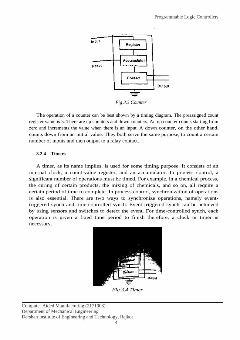
Programmable Logic Controllers
Computer Aided Manufacturing (2171903)
Department of Mechanical Engineering
Darshan Institute of Engineering and Technology, Rajkot
4
Fig 3.3 Counter
The operation of a counter can be best shown by a timing diagram. The preassigned count
register value is 5. There are up counters and down counters. An up counter counts starting from
zero and increments the value when there is an input. A down counter, on the other hand,
counts down from an initial value. They both serve the same purpose, to count a certain
number of inputs and then output to a relay contact.
3.2.4 Timers
A timer, as its name implies, is used for some timing purpose. It consists of an
internal clock, a count-value register, and an accumulator. In process control, a
significant number of operations must be timed. For example, in a chemical process,
the curing of certain products, the mixing of chemicals, and so on, all require a
certain period of time to complete. In process control, synchronization of operations
is also essential. There are two ways to synchronize operations, namely event-
triggered synch and time-controlled synch. Event triggered synch can be achieved
by using sensors and switches to detect the event. For time-controlled synch, each
operation is given a fixed time period to finish therefore, a clock or timer is
necessary.
Fig 3.4 Timer

Programmable Logic Controllers
Computer Aided Manufacturing (2171903)
Department of Mechanical Engineering
Darshan Institute of Engineering and Technology, Rajkot
5
3.3 PROGRAMMABLE CONTROLLER ARCHITECITECTURE
Programmable logic controllers replace most of the wiring by software programming. Therefore
the task is made much easier, because the wires and the moving mechanical components are
mostly replaced by software, the system is much more reliable.
Like a general purpose computer a programmable controller consists of five major parts are the
CPU (processor), memory, input/output, power supply and peripherals.
3.3.1 The Processor
Although early PLCs used special-purpose logic circuits, most current PLCs are
micro-processor-based systems. The processor (central processing unit, or CPU, as it
is often called) scans the status of the input peripherals, examines the control logic to
see what action to take, and then executes the appropriate output responses.
The microprocessor based PLC has significantly increased the logical and control
capacities of programmable logic controllers. High end PLC system allow the user
to perform arithmetic and logic operations, move memory blocks, and interface with
computers, a local area network, functions and so on.
Fig 3.5 Programmable logic controller system structure
3.3.2 Memory
The memory of the PLC is important because the control program and the
peripheral status are stored there. Memory size in a PLC is measured in either bits,
bytes, or words. Because many words of memory are required, it is usually
measured in “k” increments (where 1k = 1024).

Programmable Logic Controllers
Computer Aided Manufacturing (2171903)
Department of Mechanical Engineering
Darshan Institute of Engineering and Technology, Rajkot
6
Although several types of memory are used in modern PLCs, memory can be
classified into two basic categories volatile and non-volatile. Volatile memory loses
state when power is removed. This may seem perfectly appropriate. However, you
must remember that the program is stored in memory, and if the power fails, the
program must be rekeyed or reread into memory, a potentially time consuming
activity. Nonvolatile memory, on the other hand, maintains the information in
memory even if the power is interrupted.
3.3.3 Input and Output
The input and output (I/O) for a PLC is normally a set of modular plug-in
peripherals (notice the difference between this definition and the one used in
computer I/0s). The I/O modules allow the PLC to accept signals from a variety of
external devices, for example, limit switches, optical sensors, and proximity
switches. The signals (two state signals for the devices mentioned, open or closed)
are converted from an external voltage (115 VAC, 230 VAC, 24 VDC) to a TTL
signal of ±5 VDC. The PLC Processor then uses these signals to determine the
appropriate output response. A 5 VDC signal is transmitted to the appropriate output
module, which converts the signal to the appropriate response domain (115 VAC,
230 VAC, 24 VDC).
Normally, a peripheral interface adapter is used to transfer the status of the input
peripherals to some prespecified memory location. The user defines the location of
the peripheral on the I/O housing in the program. Each I/O location is assigned to a
specific memory location. This makes accessing input by the CPU a task of loading
the content of a specific memory into a storage register. Output changes are equally
easy for the CPU to perform. The content of a particular memory location are then
altered. Due to the electrical difference between the CPU and the external I/O
peripheral, the I/O points and the internal memory are actually electrically isolated.
In a more advanced design, a separate I/O processor is used to bring the external I/O
status to an internal memory location.
I/O module are typically housed in a rack separate from the PLC. Light indicators
are usually included in the I/O module to provide the current state. In addition, each
module is normally fused and isolated from the processor.
3.3.4 Power Supply
The power supply operates on AC power to provide the DC power required for
the controller’s internal operation. It is design to take either 115 or 220 VAC. Some
power supplies can take either voltage with a jumper switch for selection. The
operation of I/O modules is also supported by the PLCs’ power supply. However,
separate power source are required in order to close the circuit of switches, motors
and external devices.

Programmable Logic Controllers
Computer Aided Manufacturing (2171903)
Department of Mechanical Engineering
Darshan Institute of Engineering and Technology, Rajkot
7
3.3.5 Peripherals
A number of peripheral devices are available. They are used to program the PLC,
prepare the program listing, back up the program and display the system status. Old
PLCs may still have handheld programmers and CRT programmers, today they have
been replaced by a PC-based software programming environment. Following is a
partial list of peripherals.
1 Operator console
2 Printer
3 Simulator
4 EPROM loader
5 Network Communication Interface
6 PC-based programming software
3.4 PROGRAMMING A PROGARMMABLE LOGIC CONTROLLER
Programmable logic controllers were initially developed to replace relay devices. The
programming language used was similar to that used by electrical technicians to design electric
circuits—the ladder diagram. However, as PLCs grew more powerful and flexible, the limitations
of the ladder diagram soon became apparent. Not only does the ladder diagram have no easy way
to represent data manipulation, but it is also extremely difficult to write and debug a large and
complex ladder diagram. In recent years, many high-end PLCs began to introduce high level
languages.
3.4.1 Ladder diagram
A ladder diagram is a means of graphically representing the logic required in a relay logic
system. Ladder diagrams have long preceded the PLC and still represent the basic logic required
by a relay device or PLC. The fundamental ladder diagram consists of a series of input, timers,
and counters. Most simply the ladder diagram represents the action required as a function of a
series of inputs that are either on or off. Each ladder-diagram element is represented using some
standard symbols; some commonly used ones are shown in figure.
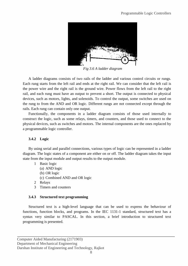
Programmable Logic Controllers
Computer Aided Manufacturing (2171903)
Department of Mechanical Engineering
Darshan Institute of Engineering and Technology, Rajkot
8
Fig 3.6 A ladder diagram
A ladder diagrams consists of two rails of the ladder and various control circuits or rungs.
Each rung starts from the left rail and ends at the right rail. We can consider that the left rail is
the power wire and the right rail is the ground wire. Power flows from the left rail to the right
rail, and each rung must have an output to prevent a short. The output is connected to physical
devices, such as motors, lights, and solenoids. To control the output, some switches are used on
the rung to from the AND and OR logic. Different rungs are not connected except through the
rails. Each rung can contain only one output.
Functionally, the components in a ladder diagram consists of those used internally to
construct the logic, such as some relays, timers, and counters, and those used to connect to the
physical devices, such as switches and motors. The internal components are the ones replaced by
a programmable logic controller.
3.4.2 Logic
By using serial and parallel connections, various types of logic can be represented in a ladder
diagram. The logic states of a component are either on or off. The ladder diagram takes the input
state from the input module and output results to the output module.
1 Basic logic
(a) AND logic
(b) OR logic
(c) Combined AND and OR logic
2 Relays
3 Timers and counters
3.4.3 Structured text programming
Structured text is a high-level language that can be used to express the behaviour of
functions, function blocks, and programs. In the IEC 1131-1 standard, structured text has a
syntax very similar to PASCAL. In this section, a brief introduction to structured text
programming is presented.

Programmable Logic Controllers
Computer Aided Manufacturing (2171903)
Department of Mechanical Engineering
Darshan Institute of Engineering and Technology, Rajkot
9
Structured text is a strongly typed language. That means that all variables used in the program
have to be declared before they can be used. The language also provides the following
functionalities:
1) Assignments
2) Expressions
3) Statements
4) Operators
5) Function calls
6) Flow control, such as conditional statements and iteration statements.
3.4.4 Function block programming
In the IEC 1131-3 standard, a functional block is a well-packaged element of software that
can be refused in different parts of an application or even in different projects. Functional blocks
are the basic building blocks of a control system and can have algorithms written in any of the
IEC languages. A function block type contains two parts: (1) data declarations, and (2) an
algorithm expressed using a structured text, a function block diagram, a ladder diagram, an
instruction list, or a sequential function chart. A functional block also can be used directly in a
ladder diagram.
3.4.5 Instruction list
The instruction list is a low-level language that has a structure similar to an assembly
language. Because it is simple, it is easy to learn and ideal for small handheld programming
devices. The instruction list has a simple syntax. Each line of code can be divided into four
fields: label, operator, operand, and comment. Label and comment fields are optional.
3.4.6 Sequential function chart
The sequential function chart is a graphics language used for depicting sequential behaviour.
The IEC standard grew out of the French standard, Grafcet, which in turn is based on petri-net.
An SFC is depicted as a series of steps shown as rectangular boxes connected by vertical lines.
Each step represents as a state of the system being controlled. A horizontal bar indicates a
condition; it can be a switch state, a timer, and so on. A condition statements is associated with
each condition bar. Each step can also can have a set of actions. The action qualifier causes the
action to behave in certain ways. The indicator variable is optional; it is for annotation purposes.
The action can be described as part of the SFC.

Programmable Logic Controllers
Computer Aided Manufacturing (2171903)
Department of Mechanical Engineering
Darshan Institute of Engineering and Technology, Rajkot
10
Fig 3.7 SFC for the material handling example
3.5 TOOLS FOR PLC LOGIC DESIGN
In this section, two analytical tools for PLC logic design are introduced. The PLC logic design
problem takes the description of a control problem and converts it into a PLC program. However,
the solution is not always obvious. Foe very simple problems, the problem description can be
translated directly into a ladder diagram or other PLC programs. When problems are more
complex, this translation is either very difficult or produces, inefficient program. The two tools
introduced in this section can help organize the problem description and convert the description
and convert the description into logic statements. Since there is a one-to-one correspondence
between logic statements and ladder diagrams, PLC programs can be written easily.
1) Design using a truth table
2) Control using a state diagram
REFERENCES
Tien-Chien Chang, Richard A. Wysk, Hsu-Pin Wang “Computer Aided Manufacturing”
3rd Edition by Pearson Education.

Group Technology & CAPP
Computer Aided Manufacturing (2171903)
Department of Mechanical Engineering
Darshan Institute of Engineering and Technology, Rajkot
1
EXPERIMENT NO. 4
AIM: To study about Group Technology and CAPP
4.1 INTRODUCTION
Group technology is a manufacturing philosophy in which similar parts are identified and grouped
together to take advantage of their similarities in manufacturing and design. Similar parts are
arranged into part families. For example, a plant producing 10,000 different part numbers may be
able to group the vast majority of this part into 50 or 60 distinct families. Each family would possess
similar design and manufacturing characteristics. Hence, the processing of each member of a given
family would be similar, and this results in manufacturing efficiencies. These efficiencies are
achieved in the form of reduced setup times, lower in-process inventories, better scheduling,
improved tool control, and the use of standardized process plans. In some plants where GT has been
implemented, the production equipment is arranged into machine groups or cells in order to facilitate
work flow and parts handling.
In product design, there are also advantages obtained by grouping parts into families. For
example, a design engineer faced with the task of developing a new part design must either start from
scratch or pull an existing drawing from the files and make the necessary changes to conform to the
requirements of the new part. The problem is that finding a similar design may be quite difficult and
time consuming. For a large engineering department, there may be thousands of drawings in the files
with no systematic way to locate the desired drawing. As a consequence, the designer may decide
that it is easier to start from scratch in developing the new part. This decision is replicated many
times over in the company, thus consuming valuable time creating duplicate or near-duplicate part
designs. If an effective design retrieval system were available, this waste could be avoided by
permitting the engineer to determine quickly if a similar part already exists. A simple change in an
existing design would be much less time consuming that starting from scratch. This design-retrieval
system is a manifestation of the group technology principle applied to the design function. To
implement such a system, some form of parts classification and coding is required.
4.2 PART FAMILIES
A part family is a collection of parts which are similar either because of geometric shape and size or
because similar processing steps are required in their manufacture. The parts within a family are
different, but their similarities are close enough to merit their identification as members of the part
family. The two parts shown in Figure 4.1 are similar from a design viewpoint but quite different in
terms of manufacturing. The parts shown in Figure 4.2 might constitute apart family in
manufacturing, but their geometry characteristics do not permit them to be grouped as a design part
family.

Group Technology & CAPP
Computer Aided Manufacturing (2171903)
Department of Mechanical Engineering
Darshan Institute of Engineering and Technology, Rajkot
2
Figure 4.1 Two parts of identical shape and size but different manufacturing requirements
Figure 4.2 Thirteen parts with similar manufacturing process requirements but different design
attributes
4.2.1 GT Layout
The various machine tools are arranged by function. There is a lathe section, milling machine
section, drill press section, and so on. During the machining of a given part, the work piece must be
moved between sections, with perhaps the same section being visited several times. This results in a
significant amount of material handling, a large in-process inventory usually more setups than
necessary, ling manufacturing lead times, and high cost. Figure 4.4 shows a production shop
supposedly equivalent capacity, but with the machines arranged into cells. Each cell is organized to
specialize in the manufacture of a particular part family. Advantages are gained in the form of
reduced work piece handling, lower setup times, less in-process inventory, less floor space and
shorter lead times. Some of the manufacturing cells can be designed to form production flow lines,
with conveyors used to transport work parts between machines in the cell.
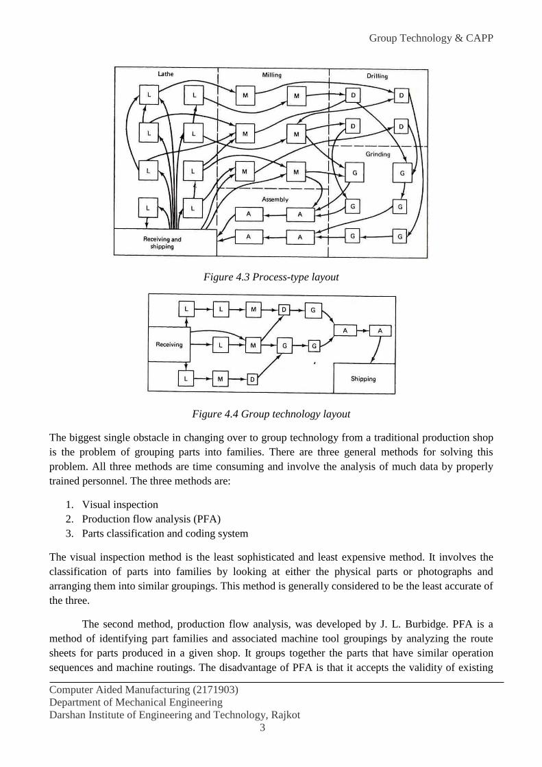
Group Technology & CAPP
Computer Aided Manufacturing (2171903)
Department of Mechanical Engineering
Darshan Institute of Engineering and Technology, Rajkot
3
Figure 4.3 Process-type layout
Figure 4.4 Group technology layout
The biggest single obstacle in changing over to group technology from a traditional production shop
is the problem of grouping parts into families. There are three general methods for solving this
problem. All three methods are time consuming and involve the analysis of much data by properly
trained personnel. The three methods are:
1. Visual inspection
2. Production flow analysis (PFA)
3. Parts classification and coding system
The visual inspection method is the least sophisticated and least expensive method. It involves the
classification of parts into families by looking at either the physical parts or photographs and
arranging them into similar groupings. This method is generally considered to be the least accurate of
the three.
The second method, production flow analysis, was developed by J. L. Burbidge. PFA is a
method of identifying part families and associated machine tool groupings by analyzing the route
sheets for parts produced in a given shop. It groups together the parts that have similar operation
sequences and machine routings. The disadvantage of PFA is that it accepts the validity of existing

Group Technology & CAPP
Computer Aided Manufacturing (2171903)
Department of Mechanical Engineering
Darshan Institute of Engineering and Technology, Rajkot
4
route sheets, with no consideration given to whether these process plans are logical or consistent.
The production flow analysis approach does not seem to be used much at all in the United States.
The third method, parts classification and coding, is the most time consuming and
complicated of the three methods. However, it is the most frequently applied method and is generally
recognized to be the most powerful of the three.
4.3 PART CLASSIFICATION AND CODING
This method of grouping parts into families involves an examination of the individual design and/or
manufacturing attributes of each part. The attributes of the part are uniquely identified by means of
code number. This classification and coding may be carried out on the entire list of active parts if the
firm or a sampling process may be used to establish the part families. For example, parts produced in
the shop during a certain given time period could be examined to identify part family categories. The
trouble with any sampling procedure is the risk that the sample may be unrepresentative of the entire
population. However, this risk may be worth taking, when compared to the relatively enormous task
of coding all the company’s parts.
Many parts classification and coding systems have been developed throughout the world, and
there are several commercially available packages being sold to industrial concerns. It should be
noted that none of them has been universally adopted. One of the reasons for this is that a
classification and coding system should be custom-engineered for a given company or industry. One
system may be best for one company while a different system is more suited to another company.
4.3.1 Design system versus manufacturing systems
Table 4.1 Design and manufacturing part attributes typically included in GT classification system
Part design attributes Part manufacturing attributes
Basic external shape Major processes
Basic internal shape Minor operations
Rotational or rectangular shape Operation sequence
Length to diameter ratio (rotational parts) Major dimension
Aspect ratio (rectangular parts) Surface finish
Material types Machine tool
Part function Production cycle time
Major dimensions Batch size
Minor dimensions Annual production
Tolerances Fixture required
Surface finish Cutting tools used in manufacturing
Parts classification and coding systems divide themselves into one of three general categories:
1. Systems based on part design attributes
2. Systems based on part manufacturing attributes
3. Systems based on both design and manufacturing attributes

Group Technology & CAPP
Computer Aided Manufacturing (2171903)
Department of Mechanical Engineering
Darshan Institute of Engineering and Technology, Rajkot
5
Systems in the first category are useful for design retrieval and to promote design standardization.
Systems in the second category are used for computer aided process planning, tool design and other
production related functions. The third category represents an attempt to combine the functions and
advantages of the other two systems into a single classification scheme. The type of design and
manufacturing parts attributes typically included in classification schemes are listed in Table 4.1. It is
clear that there is a certain amount of overlap between the design and manufacturing attributes of a
part.
4.3.2 Coding system structure
A part coding scheme consists of a sequence of symbols that identify the part’s design and/or
manufacturing attributes. The symbol in the code can be all numeric, all alphabetic, or a combination
of both types. However, most of the common classification and coding systems use number digit
only. There are three basic code structures used in group technology applications:
1. Hierarchical structure
2. Chain-type structure
3. Hybrid structure, a combination of hierarchical and chain type structures
With the hierarchical structure, the interpretation of each succeeding symbol depends on the value of
the preceding symbols. Other names commonly used for this structure are monocode and tree
structure. The hierarchical code provides a relatively compact structure which conveys much
information about the part in a limited number of digits.
In the chain-type structure, the interpretation of each symbol in the sequence is fixed and
does not depend on the value of preceding digits. Another name commonly given to this structure is
polycode. The problem associated with the polycodes is that they tend to be relatively long. On the
other hand, the use of polycode allow for convenient identification of specific part attributes. This
can be helpful in recognizing parts with similar processing requirements.
To illustrate the difference between the hierarchical structure and the chain-type structure,
consider a two-digit code, such as 15 or 25. Suppose that the first digit stands for the general part
shape. The symbol 1 means round workpart and 2 means flat rectangular geometry. In a hierarchical
code structure, the interpretation of the second digit would depend on the value of the first digit. If
preceded by 1, the 5 might indicate some length/diameter ratio, and if preceded by 2, the 5 might be
interpreted to specify some overall length. In the chain-type code structure, the symbol 5 would be
interpreted the same way regardless of the value of the first digit. For example, it might indicate
overall part length, or whether the part is rotational or rectangular.
Most of the commercial parts coding systems used in industry are a combination of the two
pure structures. The hybrid structure is an attempt to achieve the best features of monocodes and
polycodes. Hybrid codes are typically constructed as a series of polycodes. Within each of these
shorter chains, the digits are independent, but one or more symbols in the complete code number are
used to classify the part population into groups, as in the hierarchical structure. This hybrid coding
seems to best serve the needs of both design and production.

Group Technology & CAPP
Computer Aided Manufacturing (2171903)
Department of Mechanical Engineering
Darshan Institute of Engineering and Technology, Rajkot
6
4.4 THREE PARTS CLASSIFICATION AND CODING SYSTEMS
Following factors be considered in selecting a parts coding and classification systems:
Objective: The prospective user should first define the objective for the system. Will it be used for
design retrieval or part-family manufacturing or both?
Scope and application: What departments in the company will use the systems? What specific
requirements do these departments have? What kinds of information must be coded? How wide a
range of products must be coded? How complex are the parts, shapes, processes, tooling, and so
forth?
Costs and time: The Company must consider the costs of installation, training, and maintenance for
their parts classification and coding system. Will there be consulting fees, and how much? How
much time will be required to install the system and train the staff to operate and maintain it? How
long will it be before the benefits of the system are realized?
Adaptability to other systems: Can be classification and coding system be readily adapted to the
existing company computer systems and data bases? Can it be readily integrated with other existing
company procedures, such as process planning, NC programming, and production scheduling?
Management problems: It is important that all involved management personnel be informed and
supportive of the system. Also, will there be any problems with the union? Will cooperation and
support for the system be obtained from the various departments involved?
There are three parts classification and coding systems which are widely recognized among people
familiar with GT:
1. Opitz system
2. MICLASS system
3. CODE system
4.4.1 The Opitz Classification System
This part classification and coding system was developed by H. Opitz of the University of Aachen in
West Germany. It represents one of the pioneering efforts in the group technology are and is perhaps
the best known of the classification and coding schemes
The Opitz coding system uses the following digit sequence
12345 6789 ABCD
The basic consists of nine digits, which can be extended by adding four more digits. The first none
digits intended to convey both design and manufacturing data. The general interpretation of the nine
digits is indicated in Figure 4.5. The first five digits, 12345 are called the “form code” and describe
the primary design attributes of the part. The next four digits, 6789, constitute the “supplementary
code” It indicates some of the attributes that would be of use to manufacturing (dimensions, work
material, starting raw work piece shape and accuracy). The extra four digits, ABCD are referred to as
the “secondary code” and are intended to identify the production operation type and sequence. The
secondary code can be designed by the firm to serve its own particular needs.
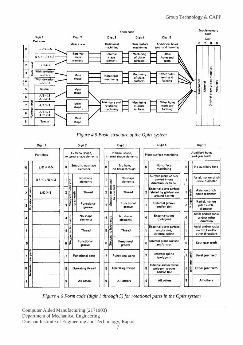
Group Technology & CAPP
Computer Aided Manufacturing (2171903)
Department of Mechanical Engineering
Darshan Institute of Engineering and Technology, Rajkot
7
Figure 4.5 Basic structure of the Opitz system
Figure 4.6 Form code (digit 1 through 5) for rotational parts in the Opitz system

Group Technology & CAPP
Computer Aided Manufacturing (2171903)
Department of Mechanical Engineering
Darshan Institute of Engineering and Technology, Rajkot
8
4.4.2 The MICLASS System
MICLASS stands for Metal Institute Classification System and was developed by TNO, the
Netherlands Organization of Applied Scientific Research. It was started in Europe about five years
before being introduced in US in 1974. The MICLASS system was developed to help automate and
standardize a number of design, production and management functions. These include
Standardization of engineering drawings
Retrieval of drawing according to classification number
Standardization of process routing
Automated process planning
Selection of parts for processing on particular groups of machine tools
Machine tool investment analysis
The MICLASS classification number can range from 12-30 digits. The first 12 digits are a
universal cod that can be applied to any part. Up to 18 additional digits can be used to code data that
are specific to the particular company or industry. For example lot size, piece time, cost data, and
operation sequence might be included in the 18 supplementary digits.
The workpart attributes coded in the first 12 digits of the MICLASS number are as follows:
1st digit Main shape
2nd and 3rd digits Shape elements
4th digit Positions of shape elements
5th and 6th digits Main dimensions
7th digit Dimension ratio
8th digit Auxiliary dimension
9th and 10th digits Tolerance codes
11th and 12th digits Material codes
One of the unique features of the MICLASS system is that parts can be coded using a
computer interactively. To classify given part design, the user responds to a series of questions asked
by the computer. The number of questions depends on the complexity of part. For a simple part, as
few as seven questions are needed to classify the part. For an average part, the number of questions
ranges between 10 and 20. On the basis of responses to its questions, the computer assigns a code
number to the part.
4.4.3 The CODE System
The CODE system is a parts classification and coding system developed and marketed by
Manufacturing Data Systems, Inc. (MDSI), of Ann Arbor Michigan. Its most universal application is
in design engineering for retrieval of part design data, but it also has applications in manufacturing
process planning, purchasing, tool design, and inventory control.

Group Technology & CAPP
Computer Aided Manufacturing (2171903)
Department of Mechanical Engineering
Darshan Institute of Engineering and Technology, Rajkot
9
Figure 4.7 A portion of the CODE system of MDSI
The CODE number has eight digits. For each digit there are 16 possible values (zero through
9 and A through F) which are used to describe the part’s design and manufacturing characteristics.
The initial digit position indicates the basic geometry of the part and is called the Major Division of
the CODE system. This digit would be used to specify whether the shape was a cylinder, flat piece
block, or other. The interpretation of the remaining seven digits depends on the value of first digit,
but these remaining digits form chain-type structure. Hence the CODE system possesses a hybrid
structure.
The second and third digits provide additional information concerning the basic geometry and
principal manufacturing process for the part. Digits 4, 5, and 6 specify secondary manufacturing
processes such as threads, grooves, slots and so forth. Digits 7 and 8 are used to indicate the overall
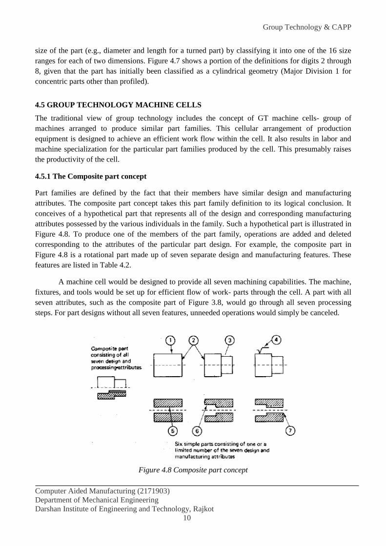
Group Technology & CAPP
Computer Aided Manufacturing (2171903)
Department of Mechanical Engineering
Darshan Institute of Engineering and Technology, Rajkot
10
size of the part (e.g., diameter and length for a turned part) by classifying it into one of the 16 size
ranges for each of two dimensions. Figure 4.7 shows a portion of the definitions for digits 2 through
8, given that the part has initially been classified as a cylindrical geometry (Major Division 1 for
concentric parts other than profiled).
4.5 GROUP TECHNOLOGY MACHINE CELLS
The traditional view of group technology includes the concept of GT machine cells- group of
machines arranged to produce similar part families. This cellular arrangement of production
equipment is designed to achieve an efficient work flow within the cell. It also results in labor and
machine specialization for the particular part families produced by the cell. This presumably raises
the productivity of the cell.
4.5.1 The Composite part concept
Part families are defined by the fact that their members have similar design and manufacturing
attributes. The composite part concept takes this part family definition to its logical conclusion. It
conceives of a hypothetical part that represents all of the design and corresponding manufacturing
attributes possessed by the various individuals in the family. Such a hypothetical part is illustrated in
Figure 4.8. To produce one of the members of the part family, operations are added and deleted
corresponding to the attributes of the particular part design. For example, the composite part in
Figure 4.8 is a rotational part made up of seven separate design and manufacturing features. These
features are listed in Table 4.2.
A machine cell would be designed to provide all seven machining capabilities. The machine,
fixtures, and tools would be set up for efficient flow of work- parts through the cell. A part with all
seven attributes, such as the composite part of Figure 3.8, would go through all seven processing
steps. For part designs without all seven features, unneeded operations would simply be canceled.
Figure 4.8 Composite part concept
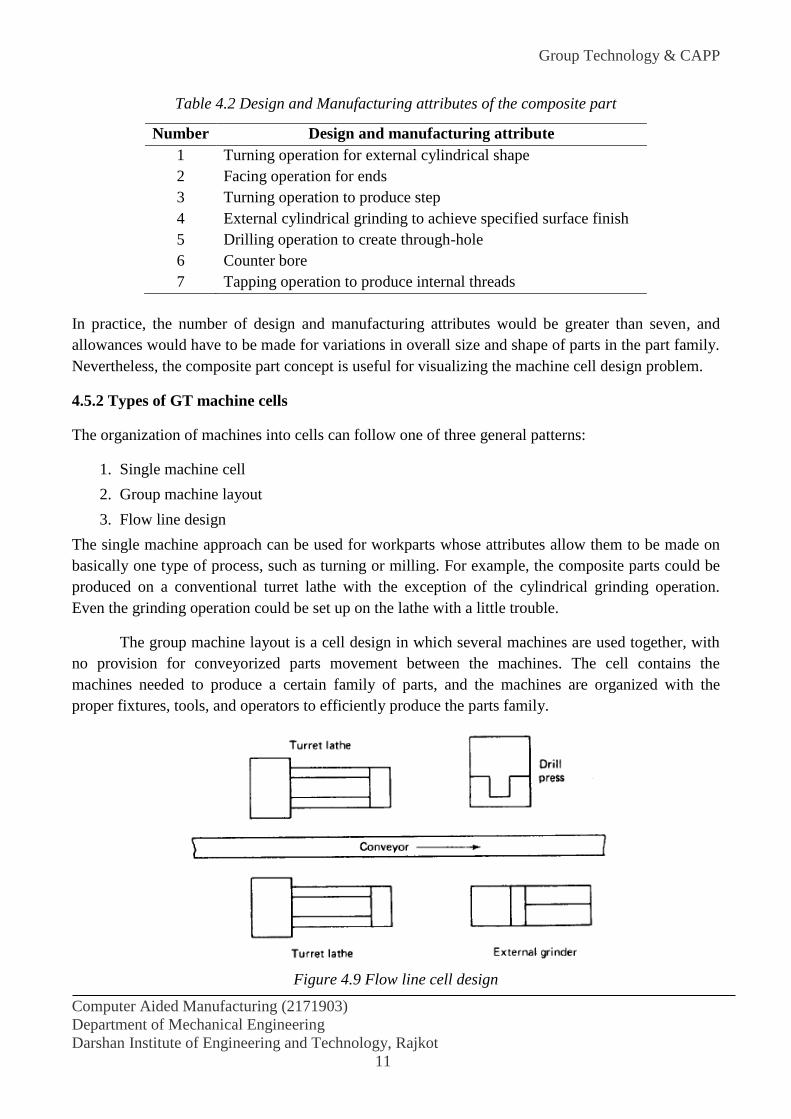
Group Technology & CAPP
Computer Aided Manufacturing (2171903)
Department of Mechanical Engineering
Darshan Institute of Engineering and Technology, Rajkot
11
Table 4.2 Design and Manufacturing attributes of the composite part
Number Design and manufacturing attribute
1 Turning operation for external cylindrical shape
2 Facing operation for ends
3 Turning operation to produce step
4 External cylindrical grinding to achieve specified surface finish
5 Drilling operation to create through-hole
6 Counter bore
7 Tapping operation to produce internal threads
In practice, the number of design and manufacturing attributes would be greater than seven, and
allowances would have to be made for variations in overall size and shape of parts in the part family.
Nevertheless, the composite part concept is useful for visualizing the machine cell design problem.
4.5.2 Types of GT machine cells
The organization of machines into cells can follow one of three general patterns:
1. Single machine cell
2. Group machine layout
3. Flow line design
The single machine approach can be used for workparts whose attributes allow them to be made on
basically one type of process, such as turning or milling. For example, the composite parts could be
produced on a conventional turret lathe with the exception of the cylindrical grinding operation.
Even the grinding operation could be set up on the lathe with a little trouble.
The group machine layout is a cell design in which several machines are used together, with
no provision for conveyorized parts movement between the machines. The cell contains the
machines needed to produce a certain family of parts, and the machines are organized with the
proper fixtures, tools, and operators to efficiently produce the parts family.
Figure 4.9 Flow line cell design
Group Technology & CAPP
Computer Aided Manufacturing (2171903)
Department of Mechanical Engineering
Darshan Institute of Engineering and Technology, Rajkot
12
The flow line cell design is a group of machines connected by a conveyor system. Although
this design approaches the efficiency of an automated transfer line, the limitation of the flow line
layout is that all the parts in the family must be processed through the machines in the same
sequence. Certain of the processing steps can be omitted, but the flow of work through the system
must be in one direction. Reversal of work flow is accommodated in the more flexible group
machine layout, but not conveniently in the flow line configuration.
4.6 BENEFITS OF GROUP TECHNOLOGY
Product design
Tooling and setups
Material handling
Production and inventory control
Employee satisfaction
Process planning procedures
Product design benefits
In the area of production design, improvement and benefits are derived from the use of a parts
classification and coding system, together with a computerized design-retrieval system. When a new
part design is required, the engineer or draftsman can devote a few minutes to figure the code of the
required part. Then the existing part designs that match the code can be retrieved to see if one of the
will serve the function desired. The few minutes spent searching the design file with the aid of the
coding system may save several hours of the designer’s time. IF the exact part design cannot be
found, perhaps a small alteration of the existing design will satisfy the function. Use of the
automated design-retrieval system helps to eliminate design duplication and proliferation of new
parts designs.
Other benefits of GT in design are that it improves cost estimating procedures and helps to promote
design standardization. Design features such as inside corner radii, chamfer, and tolerances are more
likely to become standardized with GT.
Tooling and Setups
GT also tends to promote standardization of several areas of manufacturing. Two of these areas are
tooling and setups.
In tooling, an effort is made to design group jigs and fixtures that will accommodate every member
of a parts family. Work holding devices are designed to use special adapters which convert the
general into one that can accept each part family member.
The machine tools in a GT cell do not require drastic changeovers in setup because of the similarity
in the work parts processed on them. Hence, setup time is saved, and it becomes more feasible to try
to process parts in an order so as to achieve a bare minimum of setup changeovers. It has been
estimated that the use of GT can result in 69% reduction in setup time.
Group Technology & CAPP
Computer Aided Manufacturing (2171903)
Department of Mechanical Engineering
Darshan Institute of Engineering and Technology, Rajkot
13
Material Handling
Another advantage in manufacturing is reduction in the workpart move and waiting time. The group
technology machine layouts lend themselves to efficient flow of material through the shop. The
contrast is sharpest when the flow line cell design is compared to the conventional process type
layout.
Production and Inventory Control
Several benefits accrue to a company’s production and inventory control function as a consequence
of GT.
Production scheduling is simplified with GT. In effect, grouping of machines into cells reduces the
number of production centers that must be scheduled. Grouping of parts into families reduces the
complexity and size of the parts scheduling problem. And for those work parts that cannot be
processed through any of the machine cells, more attention can be devoted to the control of these
parts. Because of the reduced setups and more efficient materials handling with machine cells,
production lead times, work-in process and late deliveries’ can be reduced. Estimates on what can be
expected are provided by DeVries.
70% reduction in production times
62% reduction in work-in-process inventories
82% reduction in overdue orders.
Employee Satisfaction
The machine cell often allows parts to be processed from raw material to finished sate by small
group workers. The workers are able to visualize their contributions to the firm more clearly. This
tends cultivate an improved worker attitude and higher level of job satisfaction,
Another employee-related benefit of GT is that more attention tends to be given to product quality.
Work part quality is more easily traced to a particular machine cell in GT. Consequently, workers are
more responsible for the quality of work they accomplish. Traceability of part defects is sometimes
very difficult in a conventional process-type layout, and quality control suffers as a result.
Process Planning Procedures
The time and cost of the process planning function can be reduced through standardization associated
with group technology. A new part design is identified by its code number as belonging to a certain
parts family, for which into computer software to form a computer-automated process planning
system.

Group Technology & CAPP
Computer Aided Manufacturing (2171903)
Department of Mechanical Engineering
Darshan Institute of Engineering and Technology, Rajkot
14
4.7 THE PLANNING FUNCTION
Process planning is concerned with determining the sequence of individual manufacturing operations
needed to produce a given part or product. The resulting operation sequence is documented on a
form typically referred to as a route sheet. The route sheet is a listing of the production operation and
associated machine tools for a work part or assembly.
Closely related to process planning are the functions of determining appropriate cutting
conditions for the machining operations and setting the time standards for the operations. All three
functions—planning the process, determining the cutting conditions, and setting the time standards—
have traditionally been carried out as tasks with a very high manual and clerical content. They are
also typically routine tasks in which similar or even identical decisions are repeated over and over.
Today, these kinds of decisions are being made with the aid of computers.
4.7.1 Traditional process planning
There are variations in the level of detail found in route sheets among different companies and
industries. In the one extreme, process planning is accomplished by releasing the part print to the
production shop with the instructions "make to drawing." Most firms provide a more detailed list of
steps describing each operation and identifying each work center. In any case, it is traditionally the
task of the manufacturing engineers or industrial engineers in an organization to write these process
plans for new part designs to be produced by the shop. The process planning procedure is very much
dependent on the experience and judgment of the planner. It is the manufacturing engineer's
responsibility to determine an optimal routing for each new part design. However, individual
engineers each have their own opinions about what constitutes the best routing. Accordingly, there
are differences among the operation sequences developed by various planners. We can illustrate
rather dramatically these differences by means of an example.
In one case, a total of 42 different routings were developed for various sizes of a relatively
simple part called an "expander sleeve." There were a total of 64 different sizes and styles, each with
its own part number. The 42 routings included 20 different machine tools in the shop. The reason for
this absence of process standardization was that many different individuals had worked on the parts:
8 or 9 manufacturing engineers, 2 planners, and 25 NC part programmers. Upon analysis, it was
determined that only two different routings through four machines were needed to process the 64
part numbers. It is clear that there are potentially great differences in the perceptions among process
planners as to what constitutes the "optimal" method of production.
In addition with problem of variability among planners, there are often difficulties in the
conventional process planning procedure. New machine tools in the factory render old routings less
than optimal. Machine breakdowns force shop personnel to use temporary routings, and these
become the documented routings even after the machine is repaired. For these reasons and others, a
significant proportion of the total numbers of process plans used in manufacturing are not optimal.

Group Technology & CAPP
Computer Aided Manufacturing (2171903)
Department of Mechanical Engineering
Darshan Institute of Engineering and Technology, Rajkot
15
4.7.2 Automated process planning
Because of the problems encountered with manual process planning, attempts have been made in
recent years to capture the logic, judgment, and experiences required for this important function and
incorporate them into computer programs. Based on the characteristics of a given part, the program
automatically generates the manufacturing operation sequence. A computer-aided process planning
(CAPP) system offers the potential for reducing the routine clerical work of manufacturing
engineers. At the same time, it provides the opportunity to generate production routings which are
rational, consistent, and perhaps even optimal. Two alternative approaches to computer-aided
process planning have been developed. These are:
1. Retrieval-type CAPP systems (also called variant systems)
2. Generative CAPP systems
The two types are described in the following two sections.
4.8 RETRIEVAL-TYPE PROCESS PLANNING SYSTEMS
Retrieval-type CAPP systems use parts classification and coding and group technology as a
foundation. In this approach, the parts produced in the plant are grouped into part families,
distinguished according to their manufacturing characteristics. For each part family, a standard
process plan is established. The standard process plan is stored in computer files and then retrieved
for new work parts which belong to that family. Some form of parts classification and coding system
is required to organize the computer files and to permit efficient retrieval of the appropriate process
plan for a new work part. For some new parts, editing of the existing process plan may be required.
This is done when the manufacturing requirements of the new part are slightly different from the
standard. The machine routing may be the same for the new part, but the specific operations required
at each machine may be different. The complete process plan must document the operations as well
as the sequence of machines through which the part must be routed. Because of the alterations that
are made in the retrieved process plan, these CAPP systems are sometimes also called by the name
"variant system.''
Figure 4.10 will help to explain the procedure used in a retrieval process planning system.
The user would initiate the procedure by entering the part code number at a computer terminal. The
CAPP program then searches the part family matrix file to determine if a match exists. If the file
contains an identical code number, the standard machine routing and operation sequence are
retrieved from the respective computer files for display to the user. The standard process plan is
examined by the user to permit any necessary editing of the plan to make it compatible with the new
part design. After editing, the process plan formatter prepares the paper document in the proper form.
If an exact match cannot be found between the code numbers in the computer file and the
code number for the new part, the user may search the machine routing file and the operation
sequence file for similar parts that could be used to develop the plan for the new part. Once the
process plan for a new part code number has been entered, it becomes the standard process for future
parts of the same classification.

Group Technology & CAPP
Computer Aided Manufacturing (2171903)
Department of Mechanical Engineering
Darshan Institute of Engineering and Technology, Rajkot
16
Figure 4.10 Information flow in a retrieval-type computer aided process planning system
In Figure 4.10 the machine routing file is distinguished from the operation sequence file to
emphasize that the machine routing may apply to a range of different part families and code
numbers. It would be easier to find a match in the machine routing file than in the operation
sequence file. Some CAPP retrieval systems would use only one such file which would be a
combination of operation sequence file and machine routing file.
The process plan formatter may use other application programs. These could include
programs to compute machining conditions, work standards, and standard costs. Standard cost
programs can be used to determine total product costs for pricing purposes.
A number of retrieval-type computer-aided process planning systems have been developed.
These include MIPLAN, one of the MICLASS modules, the CAPP system developed by Computer-
Aided manufacturing International, COMCAPP V by MDSI, and systems by individual companies.
We will use MIPLAN as an example to illustrate these industrial systems.
4.9 GENERATIVE PROCESS PLANNING SYSTEMS
Generative process planning involves the use of the computer to create individual process
plan from scratch, automatically and without human assistance. The computer would employ a set of
algorithms to progress through the various technical and logical decisions toward a final plan for
manufacturing. Inputs to the system would include a comprehensive description of the work part.

Group Technology & CAPP
Computer Aided Manufacturing (2171903)
Department of Mechanical Engineering
Darshan Institute of Engineering and Technology, Rajkot
17
This may involve the use of some form of part code number to summarize the work part data, but it
does not involve the retrieval of existing standard plans. Instead, the generative CAPP system
synthesizes the design of the optimum process sequence, based on an analysis of part geometry,
material, and other factors which would influence manufacturing decisions.
In the ideal generative process planning package, any part design could be presented to the
system for creation of the optimal plan. In practice, current generative-type systems are far from
universal in their applicability. They tend to fall short of a truly generative capability, and they are
developed for a somewhat limited range of manufacturing processes.
4.10 BENEFITS OF CAPP
Whether it is a retrieval system or a generative system, computer-aided process planning offers a
number of potential advantages over manually oriented process planning.
1. Process rationalization: Computer-automated preparation of operation routings is more
likely to be consistent, logical, and optimal than its manual counterpart. The process plans will be
consistent because the same computer software is being used by all planners. We avoid the tendency
for drastically different process plans from different planners, as described in Section 6.5. The
process plans tend to be more logical and optimal because the company has presumably incorporated
the experience and judgment of its best manufacturing people into the process planning computer
software.
2. Increased productivity of process planners: With computer-aided process planning,
there is reduced clerical effort, fewer errors are made, and the planners have immediate access to the
process planning data base. These benefits translate into higher productivity of the process planners.
One system was reported to increase productivity by 600% in the process planning function.
3. Reduced turnaround time: Working with the CAPP system, the process planner is able to
prepare a route sheet for a new part in less time compared to manual preparation. This leads to an
overall reduction in manufacturing lead time.
4. Improved legibility: The computer-prepared document is neater and easier to read than
manually written route sheets. CAPP systems employ standard text, which facilitates interpretation
of the process plan in the factory.
5. Incorporation of other application programs: The process planning system can be
designed to operate in conjunction with other software packages to automate many of the time-
consuming manufacturing support functions. We discuss two of these related planning functions,
machinability data systems and computerized work standards, in the following sections.

Group Technology & CAPP
Computer Aided Manufacturing (2171903)
Department of Mechanical Engineering
Darshan Institute of Engineering and Technology, Rajkot
18
REFERENCES:
Mikell P. Groover “Automation, Production Systems, and Computer-Integrated
Manufacturing” 3rd ed. Prentice Hall of India Private Limited, Page 518.
Groover and Zimmers “CAD/CAM ” Prentice Hall of India Private Limited, Page 275.
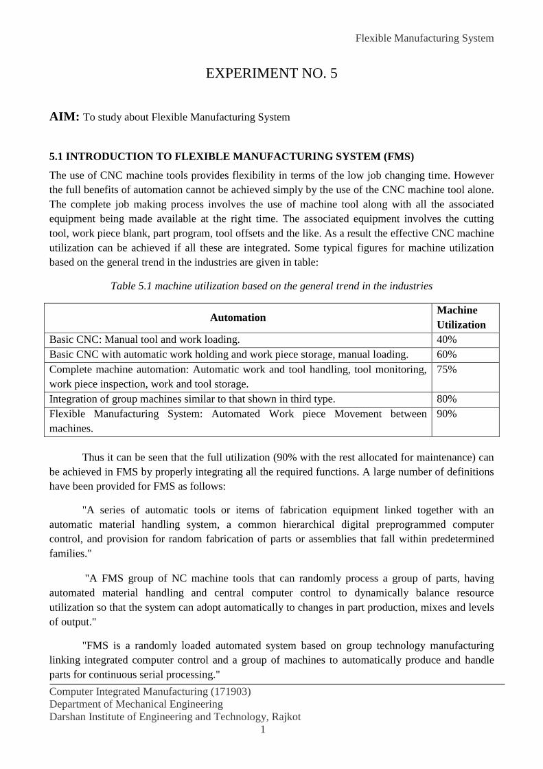
Flexible Manufacturing System
Computer Integrated Manufacturing (171903)
Department of Mechanical Engineering
Darshan Institute of Engineering and Technology, Rajkot
1
EXPERIMENT NO. 5
AIM: To study about Flexible Manufacturing System
5.1 INTRODUCTION TO FLEXIBLE MANUFACTURING SYSTEM (FMS)
The use of CNC machine tools provides flexibility in terms of the low job changing time. However
the full benefits of automation cannot be achieved simply by the use of the CNC machine tool alone.
The complete job making process involves the use of machine tool along with all the associated
equipment being made available at the right time. The associated equipment involves the cutting
tool, work piece blank, part program, tool offsets and the like. As a result the effective CNC machine
utilization can be achieved if all these are integrated. Some typical figures for machine utilization
based on the general trend in the industries are given in table:
Table 5.1 machine utilization based on the general trend in the industries
Automation Machine
Utilization
Basic CNC: Manual tool and work loading. 40%
Basic CNC with automatic work holding and work piece storage, manual loading. 60%
Complete machine automation: Automatic work and tool handling, tool monitoring,
work piece inspection, work and tool storage.
75%
Integration of group machines similar to that shown in third type. 80%
Flexible Manufacturing System: Automated Work piece Movement between
machines.
90%
Thus it can be seen that the full utilization (90% with the rest allocated for maintenance) can
be achieved in FMS by properly integrating all the required functions. A large number of definitions
have been provided for FMS as follows:
"A series of automatic tools or items of fabrication equipment linked together with an
automatic material handling system, a common hierarchical digital preprogrammed computer
control, and provision for random fabrication of parts or assemblies that fall within predetermined
families."
"A FMS group of NC machine tools that can randomly process a group of parts, having
automated material handling and central computer control to dynamically balance resource
utilization so that the system can adopt automatically to changes in part production, mixes and levels
of output."
"FMS is a randomly loaded automated system based on group technology manufacturing
linking integrated computer control and a group of machines to automatically produce and handle
parts for continuous serial processing."

Flexible Manufacturing System
Computer Integrated Manufacturing (171903)
Department of Mechanical Engineering
Darshan Institute of Engineering and Technology, Rajkot
2
"FMS combines microelectronics and mechanical engineering to bring the economies of scale
to batch work. A central online computer controls the machine tools, other workstations, and the
transfer of components and tooling. The computer also provides monitoring and information control.
This combination of flexibility and overall control makes possible the production of a wide range of
products in small numbers."
"A process under control to produce varieties of components or products within its stated
capability and to predetermined schedule."
"A technology which will help achieve leaner factories with better response times, lower unit
costs, and higher quality under an improved level of management and capital control."
Thus it can be seen that a true FMS can handle a wide variety of dissimilar parts, producing
them in small numbers even one at a time, in any order, as needed by making use of all the computer
controlled equipment (workstations and material handling) with the help of a central computer
control of all the equipment within. Typical costs associated with various types of manufacturing
systems are shown in table:
Table 5.2 Costs associated with various types of manufacturing systems
Costs Small Scale Medium Scale
(FMS)
Large Scale
(Transfer lines) (standalone machine tools)
Direct labor 43.7 24.7 19.7
Overhead 13.5 13.9 23.7
Capital 17.8 33.1 29.8
Other Costs 25 28.3 26.8
Total 100 100 100
5.2 COMPONENTS OF FMS
The components of a FMS are:
2.2.1 Workstations
The workstations vary according to the type of part being produced. In metal cutting systems, the
machines are usually computer numerically controlled (CNC) horizontal spindle machining centres,
if prismatic work pieces are to be produced, or turning centres if rotational work pieces. Some
systems consist of both types of machines, when work pieces involving both types of operation are
required. Other systems include single-purpose machines, as opposed to machining centres which are
designed to perform a range of processes. In addition to metal working machines, there may also be
gauging machines or other types of inspection machines. There are systems for sheet-metal
operations, P.C.B manufacture and assembly operations.
Flexible Manufacturing System
Computer Integrated Manufacturing (171903)
Department of Mechanical Engineering
Darshan Institute of Engineering and Technology, Rajkot
3
5.2.2 Load and unload stations
Parts have to be introduced into the system at some point and there are usually load-unload stations,
where parts are placed on pallets, usually by human operators. In some cases, parts may be supplied
by an orienting device and loaded by robot. Unloading is usually done at the same stations, but there
may be separated unload stations.
5.2.3 Work pieces transport equipment
Work pieces must be transported from the load positions to the production equipment and back for
unloading. Three types of equipment are in common use, namely conveyors, vehicles and robots.
There are loop-lines in conveyor systems for each workstation. Conveyor systems are less popular.
There are several types of vehicles: Railcars and AGVs. There are several types of mobile floor-
mounted robots, which can be used for work piece transport. Overhead gantry-robots are popular for
both work pieces and tool handling.
5.2.4 Pallets
Work pieces are normally held in pallets of some sort for transport and locating on machine tables.
Two types are common: one type of pallet serves just as a carrier for a batch of small parts, to
facilitate and reduce the frequency of movements, perhaps by a robot. This type is common in
systems which use conveyors and gantry robots, but are also used in AGV systems. The other type of
pallet is one on which one or more parts are accurately located and which is itself moved onto the
machine table and held in position while machining operations are performed on the parts.
5.2.5 Fixtures
Fixtures are used to locate parts precisely on pallets. They are usually specific to one type of part so
that each part requires a different fixture. In some cases, however, several types of part may be
sufficiently similar to make use of the same fixture. The fixtures may be permanently bolted on the
pallets, or they may be removed from the pallet when a part requiring a deferent fixture is to be
produced into the system and placed on the pallet.
5.2.6 Tools
Most operations require some form of tooling specific to the particular operation being performed
typically cutting tools in machining centers. Machining centers have tool magazines in which a set of
tools can be held so that any operation on a range of work pieces can be performed. Tools have to be
changed, because of their tool life or because the part to be worked requires tools which are not
currently in the tool magazine.
5.3 NEED OF FMS
The key objective in manufacturing is to get the right raw materials or parts to the right machines at
the right time. Too much or too soon creates backed up excess in-process inventory. Too little or too
late causes delayed work schedules and idle machines. The result in many cases is a poor use of
capital, in the form of excess in-process inventory and/or underutilization of equipment.
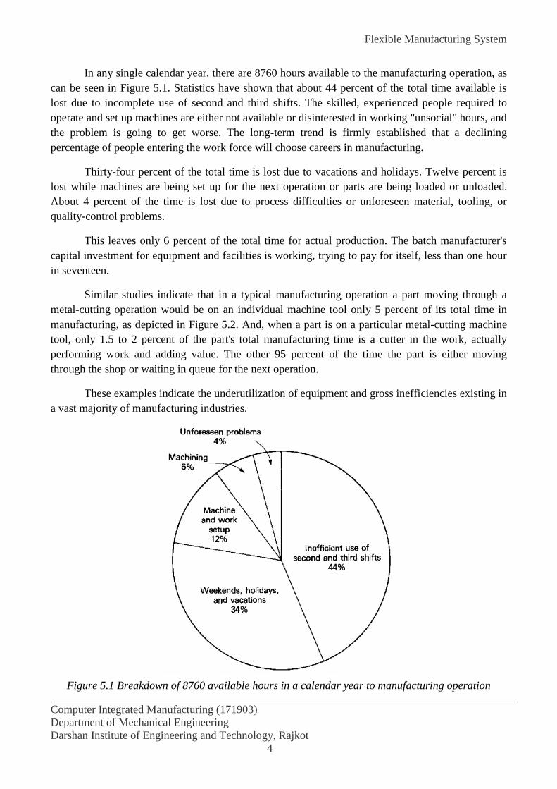
Flexible Manufacturing System
Computer Integrated Manufacturing (171903)
Department of Mechanical Engineering
Darshan Institute of Engineering and Technology, Rajkot
4
In any single calendar year, there are 8760 hours available to the manufacturing operation, as
can be seen in Figure 5.1. Statistics have shown that about 44 percent of the total time available is
lost due to incomplete use of second and third shifts. The skilled, experienced people required to
operate and set up machines are either not available or disinterested in working "unsocial" hours, and
the problem is going to get worse. The long-term trend is firmly established that a declining
percentage of people entering the work force will choose careers in manufacturing.
Thirty-four percent of the total time is lost due to vacations and holidays. Twelve percent is
lost while machines are being set up for the next operation or parts are being loaded or unloaded.
About 4 percent of the time is lost due to process difficulties or unforeseen material, tooling, or
quality-control problems.
This leaves only 6 percent of the total time for actual production. The batch manufacturer's
capital investment for equipment and facilities is working, trying to pay for itself, less than one hour
in seventeen.
Similar studies indicate that in a typical manufacturing operation a part moving through a
metal-cutting operation would be on an individual machine tool only 5 percent of its total time in
manufacturing, as depicted in Figure 5.2. And, when a part is on a particular metal-cutting machine
tool, only 1.5 to 2 percent of the part's total manufacturing time is a cutter in the work, actually
performing work and adding value. The other 95 percent of the time the part is either moving
through the shop or waiting in queue for the next operation.
These examples indicate the underutilization of equipment and gross inefficiencies existing in
a vast majority of manufacturing industries.
Figure 5.1 Breakdown of 8760 available hours in a calendar year to manufacturing operation
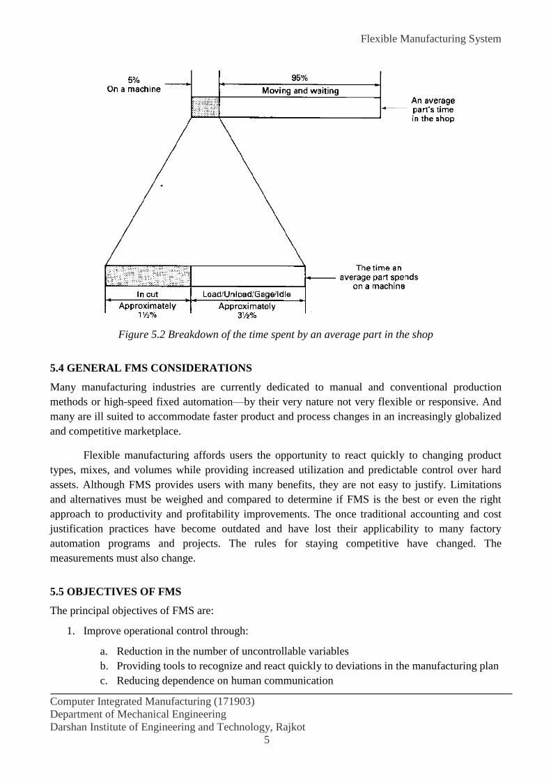
Flexible Manufacturing System
Computer Integrated Manufacturing (171903)
Department of Mechanical Engineering
Darshan Institute of Engineering and Technology, Rajkot
5
Figure 5.2 Breakdown of the time spent by an average part in the shop
5.4 GENERAL FMS CONSIDERATIONS
Many manufacturing industries are currently dedicated to manual and conventional production
methods or high-speed fixed automation—by their very nature not very flexible or responsive. And
many are ill suited to accommodate faster product and process changes in an increasingly globalized
and competitive marketplace.
Flexible manufacturing affords users the opportunity to react quickly to changing product
types, mixes, and volumes while providing increased utilization and predictable control over hard
assets. Although FMS provides users with many benefits, they are not easy to justify. Limitations
and alternatives must be weighed and compared to determine if FMS is the best or even the right
approach to productivity and profitability improvements. The once traditional accounting and cost
justification practices have become outdated and have lost their applicability to many factory
automation programs and projects. The rules for staying competitive have changed. The
measurements must also change.
5.5 OBJECTIVES OF FMS
The principal objectives of FMS are:
1. Improve operational control through:
a. Reduction in the number of uncontrollable variables
b. Providing tools to recognize and react quickly to deviations in the manufacturing plan
c. Reducing dependence on human communication

Flexible Manufacturing System
Computer Integrated Manufacturing (171903)
Department of Mechanical Engineering
Darshan Institute of Engineering and Technology, Rajkot
6
2. Reduce direct labor through:
a. Removing operators from the machining site (their responsibilities and activities can
be broadened)
b. Eliminating dependence on highly skilled machinists (their manufacturing skills can
be better utilized in manufacturing engineering functions)
c. Providing a catalyst to introduce and support unattended or lightly attended machine
operation
3. Improve short-run responsiveness consisting of:
a. Engineering changes
b. Processing changes
c. Machine downtime or unavailability
d. Cutting tool failure
e. Late material delivery
4. Improve long-run accommodations through quicker and easier assimilation of:
a. Changing product volumes
b. New product additions and introductions
c. Different part mixes
5. Increase machine utilization by:
a. Eliminating machine setup
b. Utilizing automated features to replace manual intervention
c. Providing quick transfer devices to keep machines in the cutting cycles
6. Reduce inventory by:
a. Reducing lot sizes
b. Improving inventory turnovers
c. Providing the planning tools for just-in-time manufacturing
5.6 CELLULAR VERSUS FLEXIBLE MANUFACTURING
An FMS, even though it is a unique manufacturing system, is sometimes referred to as a cell—a
highly sophisticated and automated one—among some manufacturers. And, in some cases, a single
NC machine cell or an integrated multimachine cell is referred to as a flexible manufacturing system
(FMS); in actuality, the only "flexibility" that may exist at all is changing to a different part when
similar batch requirements are completed. Although sometimes described as a cell, an FMS is set
apart from any other cell by virtue of its central computer control and highly developed software;
complete part, tooling, and material-handling flexibility and control; and randomness of production
scheduling and machining. Conventional equipment cannot compete with FMS concepts because of
the lack of management control, inherent inefficiencies, and the ever present setup and retooling
requirements.
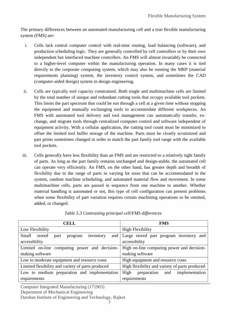
Flexible Manufacturing System
Computer Integrated Manufacturing (171903)
Department of Mechanical Engineering
Darshan Institute of Engineering and Technology, Rajkot
7
The primary differences between an automated manufacturing cell and a true flexible manufacturing
system (FMS) are:
i. Cells lack central computer control with real-time routing, load balancing (software), and
production scheduling logic. They are generally controlled by cell controllers or by their own
independent but interfaced machine controllers. An FMS will almost invariably be connected
to a higher-level computer within the manufacturing operation. In many cases it is tied
directly to the corporate computing system, which may also be running the MRP (material
requirements planning) system, the inventory control system, and sometimes the CAD
(computer-aided design) system in design engineering.
ii. Cells are typically tool capacity constrained. Both single and multimachine cells are limited
by the total number of unique and redundant cutting tools that occupy available tool pockets.
This limits the part spectrum that could be run through a cell at a given time without stopping
the equipment and manually exchanging tools to accommodate different workpieces. An
FMS with automated tool delivery and tool management can automatically transfer, ex-
change, and migrate tools through centralized computer control and software independent of
equipment activity. With a cellular application, the cutting tool count must be minimized to
offset the limited tool buffer storage of the machine. Parts must be closely scrutinized and
part prints sometimes changed in order to match the part family tool range with the available
tool pockets.
iii. Cells generally have less flexibility than an FMS and are restricted to a relatively tight family
of parts. As long as the part family remains unchanged and design-stable, the automated cell
can operate very efficiently. An FMS, on the other hand, has greater depth and breadth of
flexibility due to the range of parts in varying lot sizes that can be accommodated in the
system, random machine scheduling, and automated material flow and movement. In some
multimachine cells, parts are passed in sequence from one machine to another. Whether
material handling is automated or not, this type of cell configuration can present problems
when some flexibility of part variation requires certain machining operations to be omitted,
added, or changed.
Table 5.3 Contrasting principal cell/FMS differences
CELL FMS
Low Flexibility High Flexibility
Small stored part program inventory and
accessibility
Large stored part program inventory and
accessibility
Limited on-line computing power and decision-
making software
High on-line computing power and decision-
making software
Low to moderate equipment and resource costs High equipment and resource costs
Limited flexibility and variety of parts produced High flexibility and variety of parts produced
Low to medium preparation and implementation
requirements
High preparation and implementation
requirements
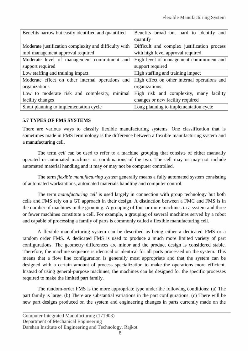
Flexible Manufacturing System
Computer Integrated Manufacturing (171903)
Department of Mechanical Engineering
Darshan Institute of Engineering and Technology, Rajkot
8
Benefits narrow but easily identified and quantified Benefits broad but hard to identify and
quantify
Moderate justification complexity and difficulty with
mid-management approval required
Difficult and complex justification process
with high-level approval required
Moderate level of management commitment and
support required
High level of management commitment and
support required
Low staffing and training impact High staffing and training impact
Moderate effect on other internal operations and
organizations
High effect on other internal operations and
organizations
Low to moderate risk and complexity, minimal
facility changes
High risk and complexity, many facility
changes or new facility required
Short planning to implementation cycle Long planning to implementation cycle
5.7 TYPES OF FMS SYSTEMS
There are various ways to classify flexible manufacturing systems. One classification that is
sometimes made in FMS terminology is the difference between a flexible manufacturing system and
a manufacturing cell.
The term cell can be used to refer to a machine grouping that consists of either manually
operated or automated machines or combinations of the two. The cell may or may not include
automated material handling and it may or may not be computer controlled.
The term flexible manufacturing system generally means a fully automated system consisting
of automated workstations, automated materials handling and computer control.
The term manufacturing cell is used largely in connection with group technology but both
cells and FMS rely on a GT approach in their design. A distinction between a FMC and FMS is in
the number of machines in the grouping. A grouping of four or more machines in a system and three
or fewer machines constitute a cell. For example, a grouping of several machines served by a robot
and capable of processing a family of parts is commonly called a flexible manufacturing cell.
A flexible manufacturing system can be described as being either a dedicated FMS or a
random order FMS. A dedicated FMS is used to produce a much more limited variety of part
configurations. The geometry differences are minor and the product design is considered stable.
Therefore, the machine sequence is identical or identical for all parts processed on the system. This
means that a flow line configuration is generally most appropriate and that the system can be
designed with a certain amount of process specialization to make the operations more efficient.
Instead of using general-purpose machines, the machines can be designed for the specific processes
required to make the limited part family.
The random-order FMS is the more appropriate type under the following conditions: (a) The
part family is large. (b) There are substantial variations in the part configurations. (c) There will be
new part designs produced on the system and engineering changes in parts currently made on the
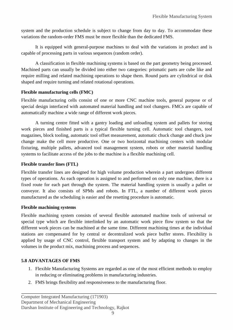
Flexible Manufacturing System
Computer Integrated Manufacturing (171903)
Department of Mechanical Engineering
Darshan Institute of Engineering and Technology, Rajkot
9
system and the production schedule is subject to change from day to day. To accommodate these
variations the random-order FMS must be more flexible than the dedicated FMS.
It is equipped with general-purpose machines to deal with the variations in product and is
capable of processing parts in various sequences (random order).
A classification in flexible machining systems is based on the part geometry being processed.
Machined parts can usually be divided into either two categories: prismatic parts are cube like and
require milling and related machining operations to shape them. Round parts are cylindrical or disk
shaped and require turning and related rotational operations.
Flexible manufacturing cells (FMC)
Flexible manufacturing cells consist of one or more CNC machine tools, general purpose or of
special design interfaced with automated material handling and tool changers. FMCs are capable of
automatically machine a wide range of different work pieces.
A turning centre fitted with a gantry loading and unloading system and pallets for storing
work pieces and finished parts is a typical flexible turning cell. Automatic tool changers, tool
magazines, block tooling, automatic tool offset measurement, automatic chuck change and chuck jaw
change make the cell more productive. One or two horizontal machining centers with modular
fixturing, multiple pallets, advanced tool management system, robots or other material handling
systems to facilitate access of the jobs to the machine is a flexible machining cell.
Flexible transfer lines (FTL)
Flexible transfer lines are designed for high volume production wherein a part undergoes different
types of operations. As each operation is assigned to and performed on only one machine, there is a
fixed route for each part through the system. The material handling system is usually a pallet or
conveyor. It also consists of SPMs and robots. In FTL, a number of different work pieces
manufactured as the scheduling is easier and the resetting procedure is automatic.
Flexible machining systems
Flexible machining system consists of several flexible automated machine tools of universal or
special type which are flexible interlinked by an automatic work piece flow system so that the
different work pieces can be machined at the same time. Different machining times at the individual
stations are compensated for by central or decentralized work piece buffer stores. Flexibility is
applied by usage of CNC control, flexible transport system and by adapting to changes in the
volumes in the product mix, machining process and sequences.
5.8 ADVANTAGES OF FMS
1. Flexible Manufacturing Systems are regarded as one of the most efficient methods to employ
in reducing or eliminating problems in manufacturing industries.
2. FMS brings flexibility and responsiveness to the manufacturing floor.
Flexible Manufacturing System
Computer Integrated Manufacturing (171903)
Department of Mechanical Engineering
Darshan Institute of Engineering and Technology, Rajkot
10
3. FMS enables manufacturers to machine a wide variety of workpieces on few machines with
low staffing levels, productively, reliably and predictably.
4. A true FMS can handle a wide variety of parts, producing them one at a time in random
order.
5. Machine tools in many manufacturing industries are woefully underutilized due to equipment
not being used in the second and third shifts, a decreasing availability of skilled personnel,
and day-to-day disturbances.
6. FMS shortens the manufacturing process through improved operational control, round-the-
clock availability of automated equipment, increased machine utilization and responsiveness,
and reduction of human intervention.
7. Better competitive advantage.
8. Lower work in process inventories
9. Reduced throughput time and its variability.
10. Improved manufacturing control.
11. Improved quality and reduced scrap rate.
12. Reduction of floor space used.
13. Better status monitor of machines, tools and material handling devices.
14. Improves the short run response time to the problems on the shop floor such as:
Demand variations,
Design and process changes that can be easily adjusted by changing the CNC part
program, which is generally developed by a CAD/CAM system as part of the design
change,
Machine unavailability can be taken care of by the FMS control system which can
automatically transfer the part to another machine that is available, and
Cutting tool failures can be detected by sensors and stop the machine thereby reducing
catastrophic failures. Then the control system can initiate steps to repair and replace the
failed cutting tool.
15. Improve the long term cost effectiveness of the system by supporting:
Changing product volumes,
Allowing different part mixes, and
Allowing new parts to be added.
5.9 TOOL MANAGEMENT SYSTEM
Tooling is one of the most important element in a manufacturing system and hence in FMS special
attention need to be given to see that the right tools are made available for machining without any
delay.
Flexible Manufacturing System
Computer Integrated Manufacturing (171903)
Department of Mechanical Engineering
Darshan Institute of Engineering and Technology, Rajkot
11
5.9.1 Tool Supply Systems
In an automated manufacturing system, cutting tools have to be taken out and supplied into the
system at intervals depending upon their utilization. If one considers the stand-alone machining
centre, tool magazine of the automatic tool changer be supplied at the beginning of the shift, all the
tools in refurbished condition. If any of the tools has to be changed during the operation, then the
machine tool may have to be stopped for changing. This would be expensive in terms of the lost
production time on the machine, and hence alternative better means have to be found for replenishing
the tools in the system. The tools need to be replaced while the machine is cutting.
But with a number of machine tools, the problem gets compounded further. Also in FMS,
when-ever the part spectrum to be manufactured gets changed, the tooling required may have to be
altered accordingly. Hence more and varied solutions have been tried by various machine tool
manufacturers. The basic concept in all the systems is to get a secondary (auxiliary) tool storage
from where the required tools can be transferred to the main i tool magazine where and when
necessary without much effort and loss of cutting time.
In the conventional method of tool changing where the machine tool will have to stop for the
complete tool magazine refurbishing with new tools or for single tool exchange. Such storage units
as drums, chains, discs and other forms are used. There is a limit to the maximum number of tools
available at the machine tool in this form. The limit may be of the order of 120 or so. Refurbishing of
the entire tool magazine is normally done during the start of the shift. Care has to be taken to see that
the tools loaded complete all the machining till the end of the scheduled period. There is no
secondary tool storage system available close to the machine tool.
In the second case, the traditional system is modified slightly. The tool magazine is split into
two or more smaller magazines, so that the machine tool can be running while one of the tool
magazines is being replenished. Sometimes the second and subsequent tool drums (discs or chains)
carry special tooling required less often for special jobs. One of the disadvantages is that if a job
requires more tools than can be accommodated in the small capacity of the drum or disc, more
frequent disc transfers would be required. This would make the tool change time small, but would
increase the cost of tools in the system higher than in the previous case. Hence this method is not
widely practised.
In the third system, an entire tool magazine is swapped for replenishment so that tool
resharpening and replacement into the magazine can be done in the tool crib. An automated guided
vehicle carries the tool magazine from the machine tool to the tool crib. Though this reduces tool
changeover time, the additional cost of a replaceable tool magazine and the system of transporting it
to the tool crib and back, makes it a more expensive proposition. However, it is possible to reduce
the total number of tools in the system by making for a tool magazine with fewer tools.
5.9.2 Tool Monitoring Systems
In the case of tool monitoring systems, the tool has to be continuously monitored while it is cutting.
This would allow for continuously looking for tool wear, as well as the times when the tool breaks

Flexible Manufacturing System
Computer Integrated Manufacturing (171903)
Department of Mechanical Engineering
Darshan Institute of Engineering and Technology, Rajkot
12
because of unforeseen conditions in the machining system. The various methods adopted for these
two functions are slightly different.
Tool Wear Monitoring
Tool wear is a phenomenon whose behaviour can be explained qualitatively but not quantitatively.
An important process parameter is the tool wear, which may be measured directly or indirectly. The
following principles are generally used for direct measurement of tool wear.
(i) Tool wear is measured by relating it to changes in the resistivity of a resistor embedded in the
tool tip. In this method there is no need to interrupt the process.
(ii) The profile of the tool tip is recorded periodically using optical methods and tool wear is
determined from the variations.
(iii) Opto-electrical methods using TV cameras and photodiodes etc. are employed to record
variations in the cutting edge to measure the width of the worn edge.
All the above methods are complex and are more expensive to implement on a regular basis on the
production CNC machine tools. As a result, tool wear measurement has to be indirect. Some
parameters used for measuring tool wear are:
Cutting power
Cutting forces: By measuring cutting force using force measuring sensors. The cutting force
increases with the increasing dullness of the tool and can therefore be related to tool wear.
Vibrations: By measuring vibrations of the tool edge, i.e., tool chatter wear can also be
indirectly estimated.
Acoustic Emission
Tool temperatures: By measuring the tool tip temperature and relating it to the wear of the
tool.
Of these variables, mainly the cutting forces and power based tool monitoring systems are
commercially and widely available, whereas the others are still not proven to be widely used in
practice.
Tool Breakage Monitoring
Another problem often faced is the breakage of tool during cutting, which if not detected in time may
lead to various problems associated with spoiled jobs, particularly in unmanned machining shifts.
Hence it is necessary to have systems which can detect the breakage of tools through some means
and give an alarm to the operator, or automatically replace the tool by a sister tool from the
secondary tool storage.
In the plate sensor or any other cutting force measuring system, it is possible to detect a drop
in cutting force almost to zero from peak during a breakage. The force drops since the tool may lose
contact because of tool breakage. Hence the controller can be given the signal for either other tool
change, or stoppage till the operator attends.

Flexible Manufacturing System
Computer Integrated Manufacturing (171903)
Department of Mechanical Engineering
Darshan Institute of Engineering and Technology, Rajkot
13
Another method used by a number of machine tool manufacturers is to cheek the tool length
or tool offset at the end or beginning of the cut using the tool probes described earlier. This value is
compared with the tool values stored for the new tool. If the difference is more than a certain value
(typically 1 mm), it is considered as tool breakage. This type of system is simple, but can detect tool
breakages only after a cut. Any tool breakage during cutting remains unnoticed. However this system
does reduce the effective damage caused by broken tools.
5.10 FLEXIBILITY IN FMS
Flexibility can be defined as the collection of properties of a manufacturing system that support
changes in production activities or capabilities. A number of types of flexibility have been listed
follows:
Machine flexibility:
This defines the capability of the machines to a wide range of production of operations and part
cycles that may require. This may be characterized by having a low setup or change over time, ease
of machine programming, sufficiently large tool storage capacity and the skill and versatility of
machine operators.
Production flexibility:
This aspect refers to the range of part styles that can be produced in the system. This is dependent on
the machine flexibility and the range of machine flexibilities.
Mix flexibility:
This is the ability with which the product mix in a given system can be changed. This depends to a
great extent of the parts in the mix, the relative work content times of parts produced and the
machine flexibility.
Product flexibility:
This is the ease with which changes in product designs can be accommodated in the system. This
will depend on how closely the new part design matches the existing part family, the ability for off-
line part program preparation and the machine flexibility.
Routing flexibility:
This specifies the capacity to produce parts through alternative workstation sequences in response to
equipment breakdowns, tool failures, and other interruptions. This is facilitated by the similarity of
parts in the mix, similarity of workstations, duplication of workstations, cross-training of manual
operators and the availability of common tooling.
Volume flexibility:
This is the ability to produce parts in high and low total quantities of production depending upon the
market demand. This will depend upon the level of manual labor performing production and amount
invested in capital equipment.
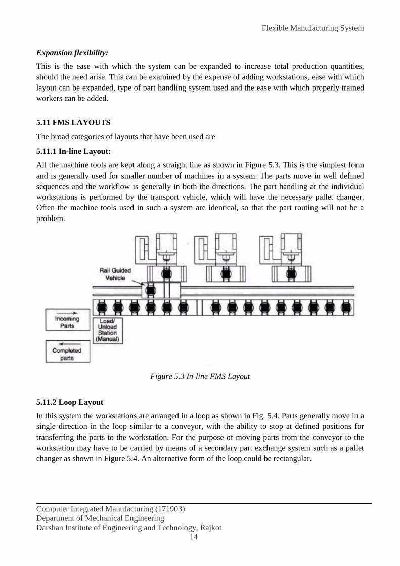
Flexible Manufacturing System
Computer Integrated Manufacturing (171903)
Department of Mechanical Engineering
Darshan Institute of Engineering and Technology, Rajkot
14
Expansion flexibility:
This is the ease with which the system can be expanded to increase total production quantities,
should the need arise. This can be examined by the expense of adding workstations, ease with which
layout can be expanded, type of part handling system used and the ease with which properly trained
workers can be added.
5.11 FMS LAYOUTS
The broad categories of layouts that have been used are
5.11.1 In-line Layout:
All the machine tools are kept along a straight line as shown in Figure 5.3. This is the simplest form
and is generally used for smaller number of machines in a system. The parts move in well defined
sequences and the workflow is generally in both the directions. The part handling at the individual
workstations is performed by the transport vehicle, which will have the necessary pallet changer.
Often the machine tools used in such a system are identical, so that the part routing will not be a
problem.
Figure 5.3 In-line FMS Layout
5.11.2 Loop Layout
In this system the workstations are arranged in a loop as shown in Fig. 5.4. Parts generally move in a
single direction in the loop similar to a conveyor, with the ability to stop at defined positions for
transferring the parts to the workstation. For the purpose of moving parts from the conveyor to the
workstation may have to be carried by means of a secondary part exchange system such as a pallet
changer as shown in Figure 5.4. An alternative form of the loop could be rectangular.

Flexible Manufacturing System
Computer Integrated Manufacturing (171903)
Department of Mechanical Engineering
Darshan Institute of Engineering and Technology, Rajkot
15
Figure 5.4 FMS Loop Layout
5.11.3 Ladder Layout
In this system the workstations are arranged in a loop with rungs as shown in Figure 5.5. The rungs
help in reducing the congestion and allow for smooth part flow between machines.
5.11.4 Open Field Layout
Figure 5.5 FMS Ladder Layout Figure 5.6 Open Field FMS Layout

Flexible Manufacturing System
Computer Integrated Manufacturing (171903)
Department of Mechanical Engineering
Darshan Institute of Engineering and Technology, Rajkot
16
In this system there are multiple loops for appropriate arrangement of all the facilities as shown in
Figure 5.6. This type of system is generally suitable for a large group of parts to be machined. The
facilities may consist of a number of workstations with different varieties. The material handling is
provided with AGVs along the guide path.
5.12 AUTOMATIC GUIDED VEHICLES
An Automated Guided Vehicle (AGV) is a programmable mobile vehicle without human
intervention. The Material Handling Institute defines it as "An AGV is a vehicle equipped with
automatic guidance equipment, either electromagnetic or optical. Such a vehicle is capable of
following prescribed guide paths and may be equipped for vehicle programming and stop selection,
blocking and any other special functions required by the system."
A typical Automated Guided Vehicle System AGVS with a pallet and work piece mounted is
shown in Figure 5.7. These are basically driver less vehicles and work generally in fixed routes that
are laid on the factory floor. The AGVS are used for work piece distribution and transferring from
stores to shop/assembly line. They are sometimes also called as robocarts. The main components of
an AGV based material handling system are:
Figure 5.7 The Automated Guided Vehicle System (AGVS) with a Work Piece
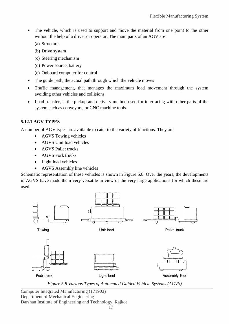
Flexible Manufacturing System
Computer Integrated Manufacturing (171903)
Department of Mechanical Engineering
Darshan Institute of Engineering and Technology, Rajkot
17
The vehicle, which is used to support and move the material from one point to the other
without the help of a driver or operator. The main parts of an AGV are
(a) Structure
(b) Drive system
(c) Steering mechanism
(d) Power source, battery
(e) Onboard computer for control
The guide path, the actual path through which the vehicle moves
Traffic management, that manages the maximum load movement through the system
avoiding other vehicles and collisions
Load transfer, is the pickup and delivery method used for interfacing with other parts of the
system such as conveyors, or CNC machine tools.
5.12.1 AGV TYPES
A number of AGV types are available to cater to the variety of functions. They are
AGVS Towing vehicles
AGVS Unit load vehicles
AGVS Pallet trucks
AGVS Fork trucks
Light load vehicles
AGVS Assembly line vehicles
Schematic representation of these vehicles is shown in Figure 5.8. Over the years, the developments
in AGVS have made them very versatile in view of the very large applications for which these are
used.
Figure 5.8 Various Types of Automated Guided Vehicle Systems (AGVS)

Flexible Manufacturing System
Computer Integrated Manufacturing (171903)
Department of Mechanical Engineering
Darshan Institute of Engineering and Technology, Rajkot
18
AGVS Towing Vehicles
These are the first types introduced and are still very popular. These are used for very large load
applications. The towing vehicle can have a variety of trailers. These are generally used for bulk
transport applications.
AGVS Unit Load Vehicles
These have a deck that permits unit load transport operation and are suitable for automatic transfer of
load. The decks can be either lift and lower type, which is most common, powered or non-powered
roller, chain, or custom design. The unit load carrier is used for moving high volumes over moderate
distances, and can easily integrate other subsystems such as conveyors and storage systems.
Figure 5.9 Typical Application Path of a Unit Load Type AGVS
Typical speeds are 50 meters per minute. They are used in warehousing and distribution systems.
Typical path of a unit load vehicle is shown in Figure 5.9. These systems have bi-directional
mobility, and operate independently. As a result they allow for good system versatility for product
movement.
AGVS Pallet Trucks
Pallet trucks are used to transport palletised loads from floor level and eliminate the need for fixed
load stands. These are used in distribution functions.
AGVS Fork Trucks
Fork trucks have the ability to service palletised loads both at floor level as well as on stands. They
may also be able to stack the loads when required. These are generally used where the heights of
load transfer vary. The vehicle has the capability of positioning to any height so that conveyors or all
load stands of varying height in a given system can be serviced. These are some of the most
expensive AGVS and can only be justified where total automation is required.

Flexible Manufacturing System
Computer Integrated Manufacturing (171903)
Department of Mechanical Engineering
Darshan Institute of Engineering and Technology, Rajkot
19
Light Load Vehicles
Light load AGVs are vehicles with small capacities of the order of 200 kg and therefore used to
transport small parts through light manufacturing environment.
AGVS Assembly Line Vehicles
These are the adoption of light load vehicles for serial assembly processes. For light assembly
applications, these vehicles carry the subassemblies such as motors or transmissions, to which parts
are added in a serial assembly operation. Prior to the assembly operation the vehicle reaches the parts
staging area where the necessary parts are placed on a tray on-board on the vehicle. The vehicle then
moves to the assembly area where the assembler completes the assembly operation taking the parts
on-board. When the assembly is completed, the vehicle is released and proceeds to the next parts
staging area.
Figure 5.10 Typical Application Path of an Assembly Line AGVS
The same process may be repeated a number of times, before the completion of the assembly. The
typical layout is shown in Figure 5.10. AGVS assembly systems allow flexibility in assembling
operation by providing for parallel operation. It is possible to track individual parts and measure
work rates.
5.12.2 GUIDANCE
AGV is operated with onboard batteries and moves generally in a fixed path. One of the
important elements in the AGV is the guidance control. The various guiding principles used in AGV
control are given in Table. The actual use of a particular guidance method mainly dependent upon
application, environment and need. The wire guidance is the most commonly used method in the
manufacturing shops.
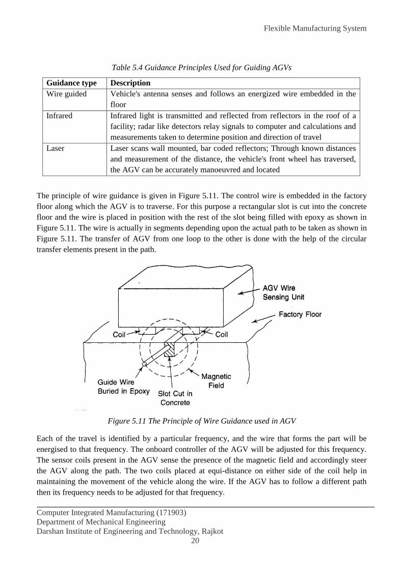
Flexible Manufacturing System
Computer Integrated Manufacturing (171903)
Department of Mechanical Engineering
Darshan Institute of Engineering and Technology, Rajkot
20
Table 5.4 Guidance Principles Used for Guiding AGVs
Guidance type Description
Wire guided Vehicle's antenna senses and follows an energized wire embedded in the
floor
Infrared Infrared light is transmitted and reflected from reflectors in the roof of a
facility; radar like detectors relay signals to computer and calculations and
measurements taken to determine position and direction of travel
Laser Laser scans wall mounted, bar coded reflectors; Through known distances
and measurement of the distance, the vehicle's front wheel has traversed,
the AGV can be accurately manoeuvred and located
The principle of wire guidance is given in Figure 5.11. The control wire is embedded in the factory
floor along which the AGV is to traverse. For this purpose a rectangular slot is cut into the concrete
floor and the wire is placed in position with the rest of the slot being filled with epoxy as shown in
Figure 5.11. The wire is actually in segments depending upon the actual path to be taken as shown in
Figure 5.11. The transfer of AGV from one loop to the other is done with the help of the circular
transfer elements present in the path.
Figure 5.11 The Principle of Wire Guidance used in AGV
Each of the travel is identified by a particular frequency, and the wire that forms the part will be
energised to that frequency. The onboard controller of the AGV will be adjusted for this frequency.
The sensor coils present in the AGV sense the presence of the magnetic field and accordingly steer
the AGV along the path. The two coils placed at equi-distance on either side of the coil help in
maintaining the movement of the vehicle along the wire. If the AGV has to follow a different path
then its frequency needs to be adjusted for that frequency.

Flexible Manufacturing System
Computer Integrated Manufacturing (171903)
Department of Mechanical Engineering
Darshan Institute of Engineering and Technology, Rajkot
21
Figure 5.12 Typical Path of a Wire Guided AGV
There are situations when the floor wired system might not be feasible for guiding the AGV
movement. Some of the situations are:
The floor is uneven and not suitable for embedding wire
There are frequent changes in the path
There are a number of metal encumbrances in the floor
Figure 5.13 Wireless Guidance of AGVS using Laser Guidance
In such cases free ranging AGVS with no fixed path using laser ranging are also available but less
used in manufacturing plants. AGVS locates its position by reading the bar code targets and by
sensing steer wheel angle and rotation as shown in Figure 5.13. The on-board computer
communicates the information processed through radio link to a stationary control computer.
Another form of the AGV is a rail-guided vehicle or RGV, which travels on fixed rails laid
out as shown in Figure 5.14. This type of vehicle is used for short travel distances and heavy work

Flexible Manufacturing System
Computer Integrated Manufacturing (171903)
Department of Mechanical Engineering
Darshan Institute of Engineering and Technology, Rajkot
22
pieces. There are not as flexible as the wire guided and therefore are used exclusively in flexible
manufacturing systems involving smaller number of machine tools. Whereas the wire guided AGVs
are used in all most all types of applications including assembly and storage.
Figure .14 Typical Path of a Rail Guided Vehicle
Since the AGVs are used for many applications, the type of work handling system to be
provided depends upon the application. Figure 5.7 shows a typical example where the pallet is
directly mounted on the AGV and is the most common form used in machining systems. Other
designs involve the provision of lift platform, telescopic loading fork, etc.
5.12.3 ADVANTAGES OF AGVS
The main advantages derived from the use of AGVs in manufacturing environment are:
(1) Dispatching, tracking and monitoring under real time computer control. This helps in planned
delivery, on line interface to production and inventory control systems, and management
information on vehicle and workstation production.
(2) Better resource utilization. Most AGVs can be justified economically in three years or less.
(3) Increased control over material flow and movement
(4) Reduced product damage and less material movement noise
(5) Routing consistency with flexibility
(6) Operational reliability in hazardous and special environment
(7) Ability to interface with various peripheral systems such as machine tools, robots and
conveyor systems
(8) Increased throughput because of dependable on-time delivery
(9) High location and positional accuracy
(10) Improved cost savings through reduction in floor space, WIP and direct labour.
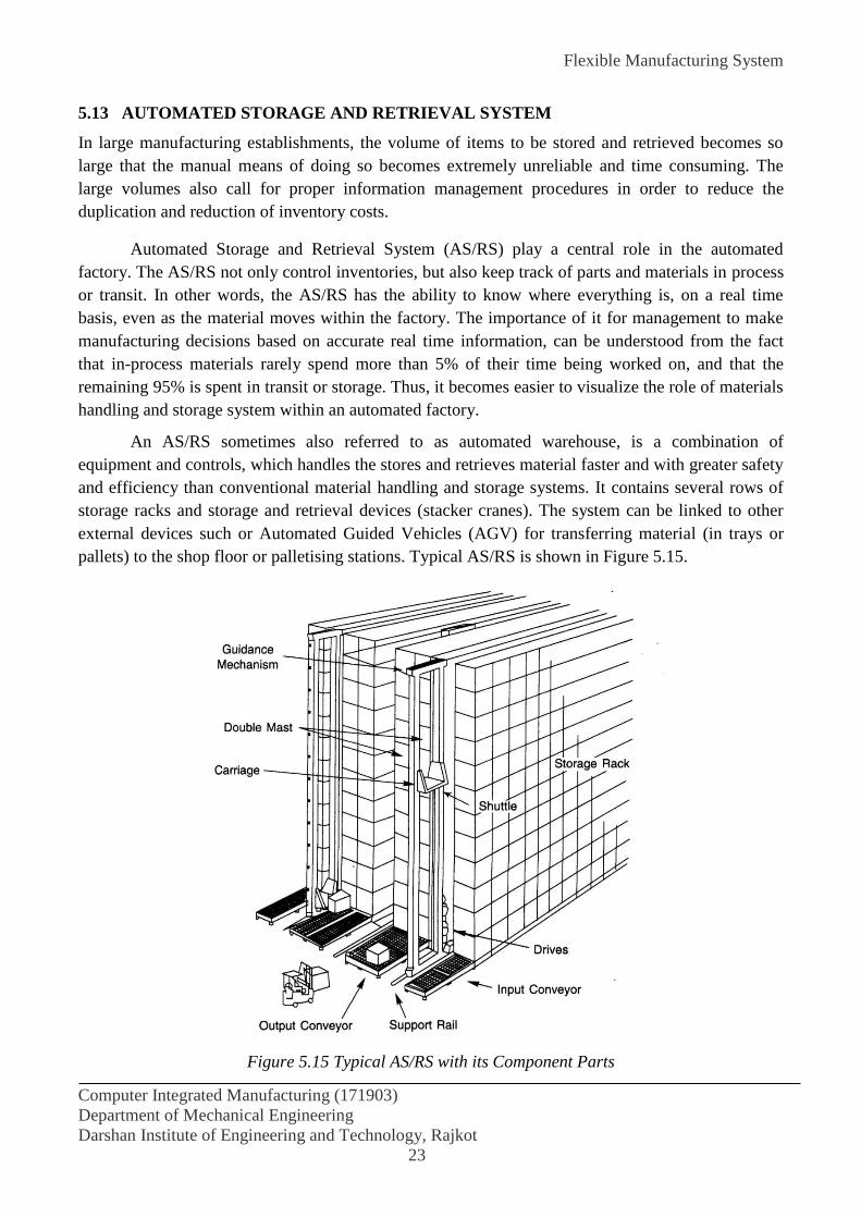
Flexible Manufacturing System
Computer Integrated Manufacturing (171903)
Department of Mechanical Engineering
Darshan Institute of Engineering and Technology, Rajkot
23
5.13 AUTOMATED STORAGE AND RETRIEVAL SYSTEM
In large manufacturing establishments, the volume of items to be stored and retrieved becomes so
large that the manual means of doing so becomes extremely unreliable and time consuming. The
large volumes also call for proper information management procedures in order to reduce the
duplication and reduction of inventory costs.
Automated Storage and Retrieval System (AS/RS) play a central role in the automated
factory. The AS/RS not only control inventories, but also keep track of parts and materials in process
or transit. In other words, the AS/RS has the ability to know where everything is, on a real time
basis, even as the material moves within the factory. The importance of it for management to make
manufacturing decisions based on accurate real time information, can be understood from the fact
that in-process materials rarely spend more than 5% of their time being worked on, and that the
remaining 95% is spent in transit or storage. Thus, it becomes easier to visualize the role of materials
handling and storage system within an automated factory.
An AS/RS sometimes also referred to as automated warehouse, is a combination of
equipment and controls, which handles the stores and retrieves material faster and with greater safety
and efficiency than conventional material handling and storage systems. It contains several rows of
storage racks and storage and retrieval devices (stacker cranes). The system can be linked to other
external devices such or Automated Guided Vehicles (AGV) for transferring material (in trays or
pallets) to the shop floor or palletising stations. Typical AS/RS is shown in Figure 5.15.
Figure 5.15 Typical AS/RS with its Component Parts

Flexible Manufacturing System
Computer Integrated Manufacturing (171903)
Department of Mechanical Engineering
Darshan Institute of Engineering and Technology, Rajkot
24
The incoming items are first sorted and assigned to pallets. The pallet loads are then routed
through weighing and sizing stations to ensure that they are within the load and size limits. The
accepted ones are transported to the pick up and delivery (P and D) stations, with the details of the
pallet contents communicated to the central computer. This computer assigns the pallet a storage
location in the rack and stores the location in its memory. The pallet is moved from P and D station
to storage by storage and retrieval machines (S/R machines), or stacker crane. Upon receipt of a
request for an item, the computer will search its memory for storage location and direct the stacker
crane to retrieve the pallet. The supporting transportation will transport the pallets from P and D
station to its destination. The major components of an AS/RS are:
(i) Storage and Retrieval machine (shuttle crane or stacker crane),
(ii) Storage structures,
(iii) Transport devices (AGV, Conveyor, etc.), and
(iv) Controls
(a) Storage and Retrieval machine (S/R machine)
The S/R machine is characterized by its ability to operate accurately and safely at high
speeds, reach heights of 30 m or beyond, and operate in aisles only a few cm wider than the load it
carries.
Figure 5.16 Physical Arrangement of the Aisle and Storage Structures in an Automatic and Retrieval
Systems
The modern S/R machine runs on a floor-mounted rail and guided at the top. It comes in a
wide variety of sizes and configurations, because its design is a function of the load it carries and the
task performs. Speed is generally determined by the system's throughput requirements (i.e., how
many loads need to be stored and retrieved in an hour). Travelling speeds sometimes exceed 150
m/min while hoisting speeds can be as high as 50 m/min.

Flexible Manufacturing System
Computer Integrated Manufacturing (171903)
Department of Mechanical Engineering
Darshan Institute of Engineering and Technology, Rajkot
25
(b) Storage Structure
The storage structure (racking) is a critical part of the AS/RS. It differs considerably from
conventional pallet racking in that AS/RS storage racks are normally much higher and interface
directly with the S/R machines, thus making manufacturing and installation tolerances more critical.
AS/RS rack design must provide for integration with S/R machine guide rails.
The most common storage structures are free-standing and installed inside a building.
Specifications differ, depending on type of load to be stored and system configuration. Today an
increasing number of systems are rack supported: that is, the rack storage structure supports the
building itself. This type of system can be over 30 metres tall and is popular because it reduces
construction tine and cost.
(c) Transport Devices
The transport (system) device moves the loads beyond the limit of the S/R machine. Some systems
need only a conveyor, while larger and more complex installations require elaborate transport
devices connecting the S/R with other factory operations. There are many types of transport devices
which can be used with an AS/RS: fork lifts, roller or chain conveyors, overhead power and free
conveyors, in-floor tow-lines, shuttle trolleys and automated guided vehicles. The choice depends on
the through-put requirements, type of load to be handled, and degree of interaction with shipping,
receiving, manufacturing, assembly and other plant operations. An example system that links with a
conveyor and AGV is shown in Figure 5.17.
Figure 5.17 Physical Layout of Automatic Storage and Retrieval System Linked with AGV for
Further Movement
Flexible Manufacturing System
Computer Integrated Manufacturing (171903)
Department of Mechanical Engineering
Darshan Institute of Engineering and Technology, Rajkot
26
(d) System Controls
The system controls encompass two functions, the control of equipment and the control of data. This
computer control system may also perform tasks like inventory control, data automation, networking
control and is frequently linked to an even larger corporate management information system
computer.
5.13.2 ADVATAGES OF AS/RS
Absolute inventory accountability is one of the most important benefits of an AS/RS. By knowing
exactly how much of what materials are located at any given moment, inventory reductions are quite
common and higher reductions are frequently realised. In addition, these systems discourage
pilferage and generate very little product or equipment damage. The systems can also improve
customer service and working conditions, and thus results in less indirect cost associated with
supervision, administration, facilities and security. The following are the benefits of using an AS/RS
Better space utilization
Less direct and indirect labour
Reduced inventories
Less energy consumption
Reduced pilferage
Less product damage
Improved working conditions
Easier housekeeping
Less equipment damage
Improved customer service
Better management control
5.14 WORKPIECE HANDLING SYSTEM
This system has the function of timely supply of unmachined work piece from the storage to the
machining centres and transporting the machined parts from the centres to the locations. This block
generally consists of the following modules:
Work piece setup or loading and unloading station
Work piece store and
Work piece transport
5.14.1 Work piece setup or loading and unloading station
Prismatic components meant for machining centres are generally setup on pallets. The pallets are
now-a-days standardized to have compatible mechanical interface with the storage locations,
transport systems, pallet changer and the machining centres. The palletization may be done manually
or with the help of a robot. Fixtures are used to locate the parts precisely on the pallets. The fixtures
should be able to accommodate several parts belonging to a family. Principle of group technology
(GT) are generally employed in this connection. The fixtures may even be permanently fixed to the
Flexible Manufacturing System
Computer Integrated Manufacturing (171903)
Department of Mechanical Engineering
Darshan Institute of Engineering and Technology, Rajkot
27
pallets which in turn may also have the provision for automatic clamping actuated hydraulically or
pneumatically. Several setup stations may be combined to constitute a central clamping and
unclamping station. When the work pieces have relatively low weight and size, they may be directly
loaded onto the machine by a robot or a manipulator. In such cases, the work pieces may be loaded
manually or automatically on tray like pallets. A transport pallet of this type may be used to
accommodate several work pieces in proper position. Rotational work pieces may also be loaded into
turning centres in a similar fashion.
5.14.2 Work piece store
Pallets with work pieces on them may be stored in expandable work piece stores. The storage
position for each of the pallets may be fixed or alternately identified as explained in pallet work
piece identification. Such stores may be used as buffer storage points for an unmanned shift.
Work piece storage and retrieval can also be automated in FMS. An FMS is generally a small
lot but great-variety manufacturing system involving frequent modifications of parts and workpiece
changeovers on the pallets.
At the same time minimization of setup time is one of the prime objectives in FMS. In this
respect, AS/RS is gaining wider acceptance for becoming a centrally controlled pallet/work piece
store working unmanned around the clock. The number of pallets which can be stored may vary
between 400 to 10,000 for small scale to large scale AS/RS. The system essentially consists of
storage racks, a PLC based or computer controlled stacker crane, the location and accuracy of which
is comparable to that of a robot. Employment of servomotors in the cranes help achieve positioning
accuracy and reliability. Elevating speeds of the stacker could be as high as 180 m/min. The AS/RS
computer is also networked in the LAN of the FMS for necessary data processing and integrated
operations. Several software modules continue to be developed to enhance AS/RS functioning so as
to include sorting of several types of work pieces, setting up rearrangements and real time changes
and positioning and allocation of cranes, and optimum utilization of the AS/RS.
5.14.3 Work piece transport
The following devices are used for transporting the work pieces from the store to the machine.
(a) Rail-mounted transport vehicles (RTV)
(b) Automatically guided vehicles (AGV)
(c) Gantry robots (GR)
An RTV can carry work pieces from the store or set up stations to all those machines which
can be interlinked with rails. This may sometimes impair access to the machines but offers a reliable
transport travelling at high speed on linear routes.
AGVs, on the other hand, do not require any rails and transport even over non-linear routes
and are widely employed. Most of these unmanned industrial trucks are inductively controlled and
consequently move at lower speeds than RTVs. Several AGVs may be used in an FMS to cover all
the routes.
Flexible Manufacturing System
Computer Integrated Manufacturing (171903)
Department of Mechanical Engineering
Darshan Institute of Engineering and Technology, Rajkot
28
Gantry robots which are essentially mobile may be used to load the work pieces directly on to
the machines from the pallets which store work pieces. This, of course, requires robot grippers which
suit the work piece geometry. Further the components should not have large dimensions and their
weight should be small. It may be noted that, in this case, several of the expensive fixtures, which
would otherwise be used to mount the work pieces on the pallets, are not required. Alternatively a
gantry robot moving along a linear overhead gantry may be used to transport work piece-set pallets
from the store or setup stations to the machines.
5.15 FLEXIBLE FIXTURING
A flexible (adaptable) fixture has been defined as a single device that holds parts of various shapes
and sizes that are subjected to the wide variety of external force fields and torques associated with
conventional manufacturing operations. Flexibility is a property of the fixturing device that makes it
conform to the workpiece geometry. Flexible fixtures offer the following advantages
(1) Reduction in lead time and effort required for designing special fixtures;
(2) Lower overhead cost of storing a multiplicity of fixtures required to effect a rapid changeover
between different manufacturing operations; and
(3) Simpler programming requirements.
Designs of various "resettable" fixtures for use in an FMS have been proposed. These fixtures
have a common location scheme for a group of workpieces, and just resetting the clamping element
is required when a new workpiece is introduced.
A number of individuals have surveyed flexible-fixturing methodologies. Broadly, there are
two major groups of flexible fixtures: discrete contact and continuous contact. In the discrete-contact
type, there are a finite number of contact points that can be arranged in space to give different
configurations. A continuous-contact fixture is a fixture in which the number of contact points is
infinite, such as a line or area contact. A point contact would completely constrain the motion in a
direction normal to the workpiece surface only. Motions parallel to the workpiece surface would not
be completely constrained, because of the limited friction in point contact. Surface contact would not
only constrain the motion of the workpiece along the three axes, but also would constrain the applied
moments.
REFERENCES:
P.N. Rao “CAD/CAM Principles and Applications” 2nd ed. Tata McGraw Hill.
Lalit Narayan “CAD/CAM ” Prentice Hall of India Private Limited.
Willium W. Luggen “Flexible Manufacturing Cells and Systems” Prentice Hall, Englewood
Cliffs, New Jersey 07632.
Robot Technology
Computer Aided Manufacturing (2171903)
Department of Mechanical Engineering
Darshan Institute of Engineering and Technology, Rajkot
1
EXPERIMENT NO. 6
AIM: To Study about Robotics and its applications.
6.1 INTRODUCTION
Robot is an automatically controlled material handling unit that is widely used in the manufacturing
industry. It is generally used for high volume production and better quality. Implementation of robot
technology with integration of automatic system can contribute to increasing of productivity of the
company and enhances the profitability of the company.
The word 'robot' first appeared in 1921 in the Czech playwright Karel Capek's play 'Rossum's
Universal Robots'. The word is linked to Czech words Robota (meaning work) and Robotnik
(meaning-slave). Computer Aided Manufactures International of USA describes the meaning of robot
as a device that performs functions ordinarily ascribed to human beings, or operates with what appears
to human intelligence. Another definition from Robot Institute of America is a programmable multi-
function manipulator designed to move and manipulate material, parts, tools or specialized devices
through variable programmed motions for the performance of a variety of specified tasks.
ISO defines a robot as: A robot is an automatically controlled, reprogrammable, multipurpose,
manipulative machine with several reprogrammable axes, which is either fixed in a place or mobile for
use in industrial automation application.
There are a number of successful examples of robot applications such as:
Robots perform more than 98% of the spot welding on Ford's Taurus and Sable cars in
U.S.A.
A robot drills 660 holes in the vertical tail fins of a F-16 fighter in 3 hours at General
Dynamics compared to 24 man-hours when the job was done manually.
Robots insert disk drives into personal computers and snap keys onto electronic typewriter
keyboards.
6.2 INDUSTRIAL ROBOTS
The industry continues to grow and expand. Currently, there are approximately thirty robot
manufacturers in the United States and over five hundred worldwide. The annual growth rate of the
industry is approximately 36 percent per year, and continued market expansion is expected. RIA
estimates that annual sales volumes for 1998 will be in the $2 billion range; for the year 2000 it is
predicted to be about $7 billion. Spot-welding still remains the largest application area for robots today.
Competitive forces are beginning to segment the market with many manufacturers focusing on
specific industries or applications. This specialization approach will speed technological advancements
and enhance robot capabilities in specific areas. More attention is being paid lately by manufacturers to
sensor integration. More and more robots are sold with standard or optional capabilities, such as vision
and tactile sensors and even fuzzy logic controls.

Robot Technology
Computer Aided Manufacturing (2171903)
Department of Mechanical Engineering
Darshan Institute of Engineering and Technology, Rajkot
2
The development of the industrial robot represents a logical evolution of automated equipment,
combining certain features of fixed automation and human labor. Robots can be thought of as
specialized machine tools with a degree of flexibility that distinguishes them from fixed-purpose
automation. By the addition of sensory devices, robots are gaining the ability to adapt to their work
environment and modify their actions based on work-condition variations. Industrial robots are
becoming "smarter" mechanical workers and are now widely accepted as valuable productivity-
improvement tools.
Industrial robots are properly thought of as machines or mechanical arms. It is inappropriate to
think of them as mechanical people. A robot is essentially a mechanical arm that is bolted to the floor, a
machine, the ceiling, or, in some cases, the wall, fitted with its mechanical hand, and taught to do
repetitive tasks in a controlled, ordered environment. In most cases, it possesses neither the ability to
move about the plant nor the ability to see or feel the part it is working on. Exceptions to these general
rules exist in certain instances. However, even with these limitations, robots make outstanding
contributions toward the improvement of manufacturing operations. Robots fill the gap between the
specialized and limited capabilities normally associated with fixed automation and the extreme
flexibility of human labor.
6.3 ROBOT PHYSICAL CONFIGURATIONS
Commercially available industrial robots have one of the following four configurations:
1. Cartesian coordinate configuration
2. Polar coordinate configuration
3. Cylindrical coordinate configuration
4. Jointed arm configuration
6.3.1 Cartesian Coordinates
Figure 6.1 Typical Motions of a Cartesian or Rectilinear Robot

Robot Technology
Computer Aided Manufacturing (2171903)
Department of Mechanical Engineering
Darshan Institute of Engineering and Technology, Rajkot
3
Positioning may be done by linear motion along three principal axes: left and right, in and
out, and up and down. These axes known respectively, as the artesian axes X, Y and Z. Figure 6.1
shows a typical manipulator arm for a Cartesian coordinates robot. The work area or work envelope
serviced by the Cartesian-coordinates robot’s arm is a big box-shaped area. Programming motion for
Cartesian-coordinates robot consist of specifying to the controller the X, Y and Z values of a desired
point to be reached. The robot then moves along each axis to the desired point. This is one of the
simplest types of robots.
6.3.2 Cylindrical Coordinates
Figure 6.2 Typical Motions of a Cylindrical Robot
In this type of robot there is a rotary motion at the base followed by the two linear motions.
The axes for the cylindrical coordinates are θ, the base rotational axis; R (reach) the in-and-out axis;
and Z, the up-and down axis. The work area is the space between two concentric cylinders of the
same height. The inner cylinder represents the reach of the arm with the arm fully retracted, and the
outer cylinder represents the reach of the arm with the arm fully extended. Figure 6.2 shows the
typical cylindrical robot.
6.3.3 Spherical or Polar Coordinates
Figure 6.3 Typical Motions of a Spherical Robot.

Robot Technology
Computer Aided Manufacturing (2171903)
Department of Mechanical Engineering
Darshan Institute of Engineering and Technology, Rajkot
4
This type of robot uses mostly rotational axes. The axes for the spherical coordinates are θ,
the rotational axis; R, the reach axis; and β, the bend-up-and-down axis. The work area serviced by a
polar-coordinates robot is the space between two concentric hemispheres. The reach of the arm
defines the inner hemisphere when it is fully retracted along the R axis. The reach of the arm defines
outer hemisphere when it is fully straightened along the R axis. Figure 6.3 shows the typical robot.
6.3.4 Jointed arm configuration
The jointed arm configuration is similar in appearance to the human arm, as shown in Figure
6.4. The arm consists of several straight members connected by joints which are analogous to the
human shoulder, elbow, and wrist. The robot arm is mounted to a base which can be rotated to
provide the robot with the capacity to work within a quasi-spherical space.
Figure 6.4 Typical Motions of a Cylindrical Robot
6.3.5 SCARA Robot
Selective Compliance Assembly Robot Arm (SCARA) is a type of robot that is commonly
used for assembly application (Figure 6.6). The arm picks up a piece-part vertically from a horizontal
table, and moves it in a horizontal plane to a point just above another place on the table. Then it
lowers the part to the table at the proper point to accomplish the assembly, perhaps including a
rotation operation to insert the part into the assembly.
Figure 6.5 SCARA Robot
Robot Technology
Computer Aided Manufacturing (2171903)
Department of Mechanical Engineering
Darshan Institute of Engineering and Technology, Rajkot
5
6.4 ROBOT COMPONENTS
A robot, as a system, consists of the following elements, which are integrated together to form a
whole:
Manipulator, or rover This is the main body of the robot and consists of the links, the
joints, and other structural elements of the robot. Without other elements, the manipulator alone is
not a robot.
End effector This is the part that is connected to the last joint (hand) of a manipulator,
which generally handles objects, makes connection to other machines, or performs the required tasks.
Robot manufacturers generally do not design or sell end effectors. In most cases, all they supply is a
simple gripper. Generally, the hand of a robot has provisions for connecting specialty end effectors
that are specifically designed for a purpose. This is the job of a company’s engineers or outside
consultants to design and install the end effector on the robot and to make it work for the given
situation. A welding torch, a paint spray gun, a glue-laying device, and a parts handler are but a few
of the possibilities. In most cases, the action of the end effector is either controlled by the robot’s
controller, or the controller communicates with the end effector’s controlling device (such as a PLC).
Actuators Actuators are the “muscles” of the manipulators. Common types of actuators are
servomotors, stepper motors, pneumatic cylinders, and hydraulic cylinders. Actuators are controlled
by the controller.
Sensors Sensors are used to collect information about the internal state of the robot or to
communicate with the outside environment. As in humans, the robot controller needs to know where
each link of the robot is in order to know the robot’s configuration. Even in absolute darkness, you
still know where your arms and legs are! This is because feedback sensors in your central nervous
system embedded in your muscle tendons send information to your brain. The brain uses this
information to determine the length of your muscles, and thus, the state of your arms, legs, etc. The
same is true for robots; sensors integrated into the robot send information about each joint or link to
the controller, which determines the configuration of the robot. Robots are often equipped with
external sensory devices such as a vision system, touch and tactile sensors, speech synthesizers, etc.,
which enable the robot to communicate with the outside world.
Controller The controller is rather similar to your cerebellum, and although it does not have
the power of your brain, it still controls your motions. The controller receives its data from the
computer, controls the motions of the actuators, and coordinates the motions with the sensory
feedback information. Suppose that in order for the robot to pick up a part from a bin, it is necessary
that its first joint be at 36°. If the joint is not already at this magnitude, the controller will send a
signal to the actuator (a current to an electric motor, air to a pneumatic cylinder, or a signal to a
hydraulic servo valve), causing it to move. It will then measure the change in the joint angle through
the feedback sensor attached to the joint (a potentiometer, an encoder, etc.). When the joint reaches
the desired value, the signal is stopped. In more sophisticated robots, the velocity and the force
exerted by the robot are also controlled by the controller.
Robot Technology
Computer Aided Manufacturing (2171903)
Department of Mechanical Engineering
Darshan Institute of Engineering and Technology, Rajkot
6
Processor The processor is brain of the robot. It calculates the motions of the robot’s joints,
determines how much and how fast each joint must move to achieve the desired location and speeds,
and oversees the coordinated actions of the controller and the sensors. The processor is generally a
computer, which works like all other computers, but is dedicated to a single purpose. It requires an
operating system, programs, peripheral equipment such as monitors, and has many of the same
limitations and capabilities of a PC processor.
Software There are perhaps three groups of software that are used in a robot. One is the
operating system, which operates the computer. The second is the robotic software, which calculates
the necessary motions of each joint based on the kinematic equations of the robot. This information
is sent to the controller. This software may be at many different levels, from machine language to
sophisticated languages used by modern robots. The third group is the collection of routines and
application programs that are developed in order to use the peripheral devices of the robots, such as
vision routines, or to perform specific tasks.
It is important to note that in many systems, the controller and the processor are placed in the
same unit. Although these two units are in the same box, and even if they are integrated into the
same circuit, they have two separate functions.
6.5 ROBOT CHARACTERISTICS
The following definitions are used to characterize robot specifications:
Payload: Payload is the weight a robot can carry and still remain within its other
specifications. For example, a robot’s maximum load capacity may be much larger than its specified
payload, but at the maximum level, it may become less accurate, may not follow its intended path
accurately, or may have excessive deflections. The payload of robots compared with their own
weight is usually very small. For example, Fanuc Robotics LR Mate™ robot has a mechanical
weight of 86 lbs and a payload of 6.6 lbs, and the M-16i™ robot has a mechanical weight of 694 lbs
and a payload of 36 lbs.
Reach: Reach is the maximum distance a robot can reach within its work envelope. Many
points within the work envelope of the robot may be reached with any desired orientation (called
dexterous). However, for other points, close to the limit of robot’s reach capability, orientation
cannot be specified as desired (called nondexterous point). Reach is a function of the robot’s joint
lengths and its configuration.
Precision (validity): Precision is defined as how accurately a specified point can be reached.
This is a function of the resolution of the actuators, as well as its feedback devices. Most industrial
robots can have precision of 0.001 inch or better.
Repeatability (variability): Repeatability is how accurately the same position can be
reached if the motion is repeated many times. Suppose that a robot is driven to the same point 100
times. Since many factors may affect the accuracy of the position, the robot may not reach the same
point every time, but will be within a certain radius from the desired point. The radius of a circle that

Robot Technology
Computer Aided Manufacturing (2171903)
Department of Mechanical Engineering
Darshan Institute of Engineering and Technology, Rajkot
7
is formed by this repeated motion is called repeatability. Repeatability is much more important that
precision. If a robot is not precise, it will generally show a consistent error, which can be predicted
and thus corrected through programming. As an example, suppose that a robot is consistently off
0.06 inch to the right. In that case, all desired points can be specified at 0.06 inch to the left, and thus
the error can be eliminated. However, if the error is random, it cannot be predicted and thus cannot
be eliminated. Repeatability defines the extent of this random error. Repeatability is usually specified
for a certain number of runs. More tests yield larger (bad for manufacturers) and more realistic (good
for the users) results. Manufacturers must specify repeatability in conjunction with the number of
tests, the applied payload during the tests, and the orientation of the arm. For example, the
repeatability of an arm in a vertical direction will be different from when the arm is tested in a
horizontal configuration. Most industrial robots have repeatability in the 0.001 inch range.
6.6 BASIC ROBOT MOTIONS
Whatever the configuration, the purpose of the robot is to perform a useful task. To accomplish the
task, an end effector, or hand, is attached to the end of the robot’s arm. It is this end effector which
adapts the general-purpose robot to a particular task. To do the task, the robot arm must be capable of
moving the end effector through a sequence of motions and/or positions.
6.6.1 Six degrees of freedom
Figure 6.6 Typical six degrees of freedom in robot motion

Robot Technology
Computer Aided Manufacturing (2171903)
Department of Mechanical Engineering
Darshan Institute of Engineering and Technology, Rajkot
8
There are six basic motions, or degrees of freedom, which provide the robot with the capability to
move the end effector through the required sequence of motions. There are six degrees of freedom
are intended to emulate the versatility of movement possessed by the human arm. Not all robots are
equipped with the ability to move in all six degrees. The six basic motions consist of three arm the
body motions and three wrist motions, as illustrated in Figure 6.6 polar type robot. These motions are
described below.
Arm and body motions:
1. Vertical transverse: up-and-down motions of the arm, caused by pivoting the entire arm
about a horizontal axis or moving the arm along a vertical slide
2. Radial transverse: extension and retraction of the arm (in-and-out movement)
3. Rotational transverse: rotation about the vertical axis (right or left swivel of the robot arm)
4. Wrist swivel: rotation of the wrist
5. Wrist bend: up-or-down movement of the wrist, which also involves a rotational movement
6. Wrist yaw: right-or-left swivel of the wrist
Additional axes of motion are possible, for example, by putting the robot on a track or slide. The
slide would be mounted in the floor or in an overhead track system, thus providing a conventional
six-axis robot with a seventh degree of freedom. The gripper device is not normally considered to be
an additional axis of motion.
6.6.2 Motion systems
Similar to NC machine tool systems, the motion systems of industrial robots can be classified as
either point-to-point (PTP) or contouring (also called continuous path).
In PTP, the robot’s movement is controlled from one point location in space to another. Each
point is programmed into the robot’s control memory and then played back during the work cycle.
No particular attention is given to the path followed by the robot in its move from one point to the
next. Point-to-point robots would be quite capable of performing certain kinds of productive
operations, such as machine loading and unloading, pick-and-place activities, and spot welding.
Contouring robots have the capability to follow a closely spaced locus of point which
describe a smooth compound curve. The memory and control requirements are greater for contouring
robots than for PPT because the complete path taken by the robot must be remembered rather than
merely the end points of the motion sequence. However, in certain industrial operations, continuous
control of the work cycle path is essential to the use of robot in the operation. Examples of these
operations are paint spraying, continuous welding processes, and grasping objects moving along a
conveyor.
Robot Technology
Computer Aided Manufacturing (2171903)
Department of Mechanical Engineering
Darshan Institute of Engineering and Technology, Rajkot
9
6.7 OTHER TECHNICAL FEATURES
There are numerous other technical features of an industrial robot which determine its efficiency and
effectiveness at performing a given task. The following are some of the most important among these
technical features:
(1) Work volume
(2) Precision of movement
(3) Speed of movement
(4) Weight-carrying capacity
(5) Type of drive system
These features are described in this section.
6.7.1 Work volume
The term “work volume” refers to the space within which the robot can operate. To be technically
precise, the work volume is the spatial region within which the end of the robot’s wrist can be
manipulated. Robot manufacturers have adopted the policy of defining the work volume in terms of
the wrist end, with no hand or tool attached.
The work volume of an industrial robot is determined by its physical configuration, size, and
the limits of its arm and joint manipulations. The work volume of a Cartesian coordinate robot will
be rectangular. The work volume of a cylindrical coordinate robot will be cylindrical. A polar
coordinate configuration will generate a work volume which is a partial sphere. The work volume of
a jointed arm robot will be somewhat irregular, the outer reaches generally resembling a partial
sphere. Robot manufacturers usually show a diagram of the particular model’s work volume in their
marketing literature, providing a top view and side view with dimensions of the robot’s motion
envelope.
6.7.2 Precision of movement
The precision with which the robot can move the end of its wrist is a critical consideration in most
applications. In robotics, precision of movement is a complex issue, and we will describe it as
consisting of three attributes:
1. Spatial resolution
2. Accuracy
3. Repeatability
These attributes are generally interpreted in terms of the wrist end with no end effector attached and
with the arm fully extended.
Spatial resolution: The term “spatial resolution” refers to the smallest increment of motion at the
wrist end that can be controlled by the robot. This is determined largely by the robot’s control
resolution, which depends on its position control system and/or its feedback measurement system. In
addition, mechanical inaccuracies in the robot’s joints would tend to degrade its ability to position its

Robot Technology
Computer Aided Manufacturing (2171903)
Department of Mechanical Engineering
Darshan Institute of Engineering and Technology, Rajkot
10
arm. The spatial resolution is the sum of the control resolution plus these mechanical inaccuracies.
The factors determining control resolution are the range of movement of the arm and the bit storage
capacity in the control memory for that movement. The arm movement must be divided into its basic
motions or degrees of freedom, and the resolution of degree of freedom is figured separately. Then
the total control resolution is the vector sum of each component.
Accuracy: The accuracy of the robot refers to its capability to position its wrist end (or a tool
attached to the wrist) at a given target point within its work volume. Accuracy is closely related to
spatial resolution, since the robot’s ability to reach a particular point in space depends on its ability to
divide its joint movement into small increments. According to this relation, the accuracy of the robot
would be one-half the distance between two adjacent resolution points. The robot’s accuracy is also
affected by mechanical inaccuracies, such as deflection of its components, gear inaccuracies and so
forth.
Repeatability: This refers to the robot’s ability to position its wrist end (or tool) back to a point in
space. Repeatability is different from accuracy. The robot will initially programmed to move the
wrist end to the target point T. Because it is limited by its accuracy, the robot was only capable of
achieving point A. The distance between points A and T is the accuracy. Later, the robot is instructed
to return to this previously programmed point A. However, because it is limited by it repeatability, it
is only capable of moving to point R. The distance between points R and A is a measure of the
robot’s repeatability. As the robot is instructed to return to the same position in subsequent work
cycles, it will not always return to point R, but instead will form a cluster of positions about point A.
Repeatability errors form a random variable. In general, repeatability will be better (less) than
accuracy. Mechanical inaccuracies in the robot’s arm and wrist components are principal sources of
repeatability errors.
6.7.3 Speed of movement
The speed with which the robot can manipulate the end effector ranges up to a maximum of about
1.6 m/s. almost all robots have an adjustment to set the speed to the desirable level for the task
performed. This speed should be determined by such factors as the weight of the object being moved,
the distance moved, and the precision with which the object must be positioned during the work
cycle. Heavy-object cannot be moved as fast as light objects because of inertia problems. Also,
objects must be moved more slowly when high positional accuracy is required.
6.7.4 Weight-carrying capacity
The weight-carrying capacity of commercially available robots covers a wide range. At the upper
end of the range, there are robots capable of lifting over 1000 lb. The Versatran FC model has a
maximum load-carrying capacity rated at 2000 lb. At the lower end of the range, the ultimate PUMA
Model 260 has a load capacity of only 2.6 lb. What complicates the issue for the low-weight-capacity
robots is that the rated capacity includes the weight of the end effector. For example, if the gripper
for the PUMA 260 weights 1 lb, the net capacity of the robot is only 1.6 lb.

Robot Technology
Computer Aided Manufacturing (2171903)
Department of Mechanical Engineering
Darshan Institute of Engineering and Technology, Rajkot
11
6.7.5 Type of drive system
There are three basic drive systems used in commercially available robots:
1. Hydraulic
2. Electric motor
3. Pneumatic
Hydraulic drive systems are usually associated with large robots, and this drive system adds
to the floor space required by the robot. Advantages which this type of system gives to the robot are
mechanical simplicity, high strength, and high speed.
Robots driven by electric motors (dc stepping motors or servomotors) do not possess the
physical strength or speed of hydraulic units, but their accuracy and repeatability is generally better.
Less floor space is required due to the absence of the hydraulic power unit.
Pneumatically driven robots are typically smaller and technologically less sophisticated than
the other two types. Pick-and-place tasks and other simple, high-cycle-rate operations are examples
of the kinds of applications usually reserved for these robots.
6.8 ACTUATORS
Actuators are the muscles of robots. If you imagine that the links and the joints are the skeleton of
the robot, the actuators act as muscles, which move or rotate the links to change the configuration of
robots. The actuator must have enough power to accelerate and decelerate the links and to carry the
loads, yet be light, economical, accurate, responsive, reliable, and easy to maintain.
There are many types of actuators available, and, undoubtedly, there will be more varieties available
in the future. The following types are noteworthy:
Electric motors
Servomotors
Stepper motors
Direct-drive electric motors
Hydraulic actuators
Pneumatic actuators
Shape memory metal actuators
Magnetostrictive actuators
Electric motors — especially servomotors — are the most commonly used robotic actuators.
Hydraulic systems were very popular for large robots in the past and are still around in many places,
but are not used in new robots as often any more. Pneumatic cylinders are used in robots that have
1/2 degree of freedom, on- off type joints, as well as for insertion purposes. Direct drive electric
motors, the shape memory metal type-actuators, and others like them are mostly in research and
development stage and may become more useful in the near future.
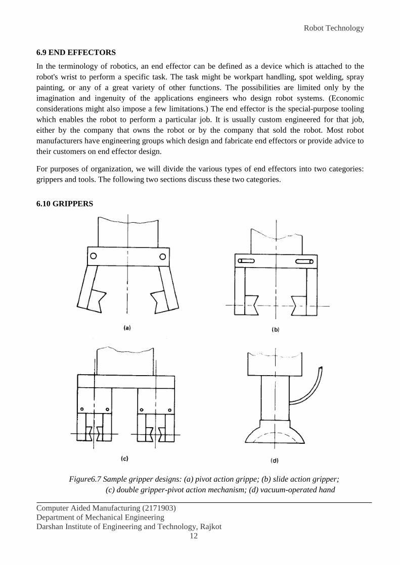
Robot Technology
Computer Aided Manufacturing (2171903)
Department of Mechanical Engineering
Darshan Institute of Engineering and Technology, Rajkot
12
6.9 END EFFECTORS
In the terminology of robotics, an end effector can be defined as a device which is attached to the
robot's wrist to perform a specific task. The task might be workpart handling, spot welding, spray
painting, or any of a great variety of other functions. The possibilities are limited only by the
imagination and ingenuity of the applications engineers who design robot systems. (Economic
considerations might also impose a few limitations.) The end effector is the special-purpose tooling
which enables the robot to perform a particular job. It is usually custom engineered for that job,
either by the company that owns the robot or by the company that sold the robot. Most robot
manufacturers have engineering groups which design and fabricate end effectors or provide advice to
their customers on end effector design.
For purposes of organization, we will divide the various types of end effectors into two categories:
grippers and tools. The following two sections discuss these two categories.
6.10 GRIPPERS
Figure6.7 Sample gripper designs: (a) pivot action grippe; (b) slide action gripper;
(c) double gripper-pivot action mechanism; (d) vacuum-operated hand

Robot Technology
Computer Aided Manufacturing (2171903)
Department of Mechanical Engineering
Darshan Institute of Engineering and Technology, Rajkot
13
Grippers are end effectors used to grasp and hold objects. The objects are generally workparts that
are to be moved by the robot. These part-handling applications include machine loading and
unloading, picking parts from a conveyor, and arranging parts onto a pallet. In addition to workparts,
other objects handled by robot grippers include cartons, bottles, raw materials, and tools. We tend to
think of grippers as mechanical grasping devices, but there are alternative ways of holding objects
involving the use of magnets, suction cups, or other means.
6.10.1 Mechanical Grippers
A mechanical gripper is an end effector that uses mechanical fingers actuated by a mechanism to
grasp an object. The fingers, sometimes called jaws, are the appendages of the gripper that actually
make contact with the object. The fingers are either attached to the mechanism or are an integral part
of the mechanism. If the fingers are of the attachable type, then they can be detached and replaced.
The use of replaceable fingers allows for wear and interchangeability.
6.10.2 Vacuum cups
Vacuum cups, also called suction cups, can be used as gripper devices for handling certain types of
objects. The usual requirements on the objects to be handled are that they be flat, smooth, and clean,
conditions necessary to form a satisfactory vacuum between the object and the suction cup. The
suction cups of robot gripper are typically made of elastic material such as rubber or soft plastic. An
exception would be when the object to be handled is composed of a soft material. In this case, the
suction cup would be made of a hard substance.
6.10.3 Magnetic Grippers
Magnetic grippers can be a very feasible means of handling ferrous materials. The stainless steel
plate would not be an appropriate application for a magnetic gripper because 18-8 stainless steel is
not attracted by a magnet. Other steels, however, including certain types of stainless steel, would be
suitable candidates for this means of handling, especially when the materials are handled in sheet or
plate form.
In general, magnetic grippers offer the following advantages in robotic handling applications:
Pickup times are very fast.
Variations in part size can be tolerated. The gripper does not have to be designed for one
particular workpart.
They have the ability to handle metal parts with holes (not possible with vacuum grippers).
They require only one surface for gripping.
Disadvantages with magnetic grippers include the residual magnetism remaining in the workpiece
which may cause a problem in subsequent handling, and the possible side slippage and other errors
which limit the precision of this means of handling.
6.10.4 Adhesive Gripper
Gripper designs in which an adhesive substance performs the grasping action can be used to handle
fabrics and other lightweight materials. The requirements on the items to be handled are that they

Robot Technology
Computer Aided Manufacturing (2171903)
Department of Mechanical Engineering
Darshan Institute of Engineering and Technology, Rajkot
14
must be gripped on one side only and that other forms of grasping such as a vacuum or magnet are
not appropriate. One of the potential limitations of an adhesive gripper is that the adhesive substance
loses its tackiness on repeated Usage. Consequently, its reliability as a gripping device is diminished
with each successive operation cycle. To overcome this limitation, the adhesive material is loaded in
the form of a continuous ribbon into a feeding mechanism that is attached to the robot wrist. The
feeding mechanism operates in a manner similar to a typewriter ribbon mechanism.
6.10.5 TOOLS AS END EFFECTORS
In many applications, the robot is required to manipulate a tool rather than a workpart. In a limited
number of these applications, the end effector is a gripper that is designed to grasp and handle the
tool. The reason for using a gripper in these applications is that there may be more than one tool to
be used by the robot in the work cycle. The use of a gripper permits the tools to be exchanged during
the cycle, and thus facilitates this multitool handling function.
In most of the robot applications in which a tool is manipulated, the tool is attached directly to the
robot wrist. In these cases the tool is the end effector. Some examples of tools used as end effectors
in robot applications include:
Spot-welding tools
Arc-welding torch
Spray-painting nozzle
Rotating spindles for operations such as:
drilling
routing
wire brushing
grinding
Liquid cement applicators for assembly
Heating torches
Water jet cutting tool
6.11 TRANSDUCERS
A transducer is a device that converts one type of physical variable (e.g., force, pressure,
temperature, velocity, flow rate, etc.) into another form. A common conversion is to electrical
voltage, and the reason for making the conversion is that the converted signal is more convenient to
use and evaluate. A sensor is a transducer that is used to make a measurement of a physical variable
of interest. Some of the common sensors and transducers include strain gauges (used to measure
force and pressure), thermocouples (temperatures), speedometers (velocity), and Pitot tubes (flow
rates).
Any sensor or transducer requires calibration in order to be useful as a measuring device.
Calibration is the procedure by which the relationship between the measured variable and the
converted output signal is established.

Robot Technology
Computer Aided Manufacturing (2171903)
Department of Mechanical Engineering
Darshan Institute of Engineering and Technology, Rajkot
15
Transducers and sensors can be classified into two basic types depending
on the form of the converted signal. The two types are:
1. Analog transducers
2. Digital transducers
Analog transducers provide a continuous analog signal such as electrical voltage or current. This
signal can then be interpreted as the value of the physical variable that is being measured. Digital
transducers produce a digital output signal, either in the form of a set of parallel status bits or a series
of pulses that can be counted. In either form, the digital signal represents the value of the measured
variable. Digital transducers are becoming more popular because of the ease with which they can be
read as separate measuring instruments. In addition, they offer the advantage in automation and
process control that they are generally more compatible with the digital computer than analog-based
sensors.
6.12 INTELLIGENT ROBOTS
Intelligent robots constitute a growing class of industrial robot that possesses the capability not only
to play back a programmed motion cycle but to also interact with its environment in a way that
seems intelligent. Invariably, the controller unit consists of a digital computer or similar device (e.g.,
programmable controller). Intelligent robots can alter their programmed cycle in response to
conditions that occur in the workplace. They can make logical decisions based on sensor data
received from the operation. The robots in this class have the capacity to communicate during the
work cycle with humans or computer-based systems. Intelligent robots are usually programmed
using an English-like and symbolic language not unlike a computer programming language. Indeed,
the kinds of applications that are performed by intelligent robots rely on the use of a high-level
language to accomplish the complex and sophisticated activities that can be accomplished by these
robots. Typical applications for intelligent robots are assembly tasks and arc-welding operations.
6.13 WORK CELL CONTROL AND INTERLOCKS
6.13.1 Work cell control
Industrial robots usually work with other things: processing equipment, workparts, conveyors, tools,
and perhaps, human operators. A means must be provided for coordinating all of the activities which
are going on within the robot workstation.
Some of the activities occur sequentially, while others take place simultaneously. To make
certain that the various activities are coordinated and occur in the proper sequence, a device called
the work cell controller is used (another name for this is workstation controller). The work cell
controller usually resides within the robot and has overall responsibility for regulating the activities
of the work cell components.
Robot Technology
Computer Aided Manufacturing (2171903)
Department of Mechanical Engineering
Darshan Institute of Engineering and Technology, Rajkot
16
6.13.2 Interlocks
An interlock is the feature of work cell control which prevents the work cycle sequence from
continuing until a certain condition or set of conditions has been satisfied. In a robotic work cell,
there are two types: outgoing and incoming. The outgoing interlock is a signal sent from the
workstation controller to some external machine or device that will cause it to operate or not operate.
For example, this would be used to prevent a machine from initiating its process until it was
commanded to proceed by the work cell controller. An incoming interlock is a signal from some
external machine or device to the work controller which determines whether or not the programmed
work cycle sequence will proceed. For example, this would be used to prevent the work cycle
program from continuing until the machine signaled that it had completed its processing of the
workpiece.
The use of interlocks provides an important benefit in the control of the work' cycle because
it prevents actions from happening when they shouldn't, and it causes actions to occur when they
should. Interlocks are needed to help coordinate the activities of the various independent components
in the work cell and to help avert damage of one component by another.
In the planning of interlocks in the robotic work cell, the application engineer must consider
both the normal sequence of activities that will occur during the work cycle, and the potential
malfunctions that might occur. Then these normal activities are linked together by means of limit
switches, pressure switches, photoelectric devices, and other system components. Malfunctions that
can be anticipated are prevented by means of similar devices.
6.14 ROBOT APPLICATIONS
Robots are best suited to work in environments where humans cannot perform the tasks. Robots have
already been used in many industries and for many purposes. They can often perform better than
humans and at lower costs. For example, a welding robot can probably weld better than a human
welder, because the robot can move more uniformly and more consistently. In addition, robots do not
need protective goggles, protective clothing, ventilation, and many other necessities that their human
counterparts do. As a result, robots can be more productive and better suited for the job. A robot
exploring the ocean bottom would require far less attention than a human diver. Also, the robot can
stay underwater for long periods and can go to very large depths and still survive the pressure; it also
does not require oxygen.
The following is a list of some applications where robots are useful. The list is not complete
by any stretch of imagination. There are many other uses as well, and other applications find their
way into the industry and the society all the time:
Machine loading, where robots supply parts to or remove parts from other machines. In this
type of work, the robot may not even perform any operation on the part, but is only a means of
handling parts within a set of operations.
Pick and place operations, where the robot picks up parts and places them elsewhere. This
may include palletizing, placing cartridges, simple assembly where two parts are put together (such

Robot Technology
Computer Aided Manufacturing (2171903)
Department of Mechanical Engineering
Darshan Institute of Engineering and Technology, Rajkot
17
as placing tablets into a bottle), placing parts in an oven and removing the treated part from the oven,
or other similar routines.
Welding, where the robot, along with proper setups and a welding end effector, is used to
weld parts together. This is one of the most common applications of robots in the auto industry. Due
to the robots' consistent movements, the welds are very uniform and accurate. Welding robots are
usually large and powerful.
Painting is another very common application of robots, especially in the automobile industry.
Since maintaining a ventilated, but clean, room suitable for humans is difficult and compared with
those performed by humans, robotic operations are more consistent, painting robots are very well
suited for their job.
Inspection of parts, circuits boards, and other similar products is also a very common
application for robots. In general, some other device is integrated into the system for inspection. This
may be a vision system, an X-ray device, an ultrasonic detector, or other similar devices. In one
application, a robot equipped with an ultrasound crack detector was given the computer-aided design
(CAD) data about the shape of an airplane fuselage and wings, and was used to follow the airplane's
body contours and check each joint, weld, or rivet. In a similar application, a robot was used to
search for and find the location of each rivet, detect and mark the rivets with fatigue cracks, drill
them out, and move on. The technicians would insert and install new rivets. Robots have also been
extensively used for circuit board and chip inspection.
Sampling with robots is used in many industries, including in agriculture. Sampling can be
similar to pick and place and inspection, except that it is performed only on a certain number of
products.
Assembly operations are among the most difficult for the robot to do. Usually, assembling
components into a product involves many operations. For example, the parts must be located and
identified, carried in a particular order with many obstacles around the setup, fitted together, and then
assembled. Many of the fitting and assembling tasks are complicated as well, and may require
pushing, turning, bending, wiggling, pressings and snapping the tabs to connect the parts.
Manufacturing by robots may include many different operations, such as material removal,
drilling, deburring, laying glue, cutting, etc. It also includes insertion of parts, such as electronic
components into circuit boards, installation of boards into electronic devices such as VCR's, and
other similar operations.
Surveillance by robots has been tried, but was not too successful. However, the use of vision
systems for surveillance has been very extensive, both in security industry and in traffic control. For
example, in one part of the highway system in Southern California, one lane of traffic has been
leased out to private industry, which maintains the road and provides services, but also charges users.
Surveillance cameras are used to detect the license plates of the cars that use the road, which are
subsequently charged a toll for road use.

Robot Technology
Computer Aided Manufacturing (2171903)
Department of Mechanical Engineering
Darshan Institute of Engineering and Technology, Rajkot
18
Medical applications are also becoming increasingly common. For example, the Robodoc
was designed to assist a surgeon in total-joint-replacement operations. Since many of the functions
that are performed during this procedure, such as cutting of the head of the bone, drilling a hole in
the bone's body, reaming the hole for precise dimension, and installation of the manufactured
implant joint, can be performed by a robot with better precision than by a human, the mechanical
parts of the operation are assigned to the robot. Similarly, many other robots have been used to assist
surgeons during microsurgery, including operation on heart valves in Paris.
Assisting disabled individuals has also been tried with interesting results. There is much that
can be done to help the disabled in their daily lives. In one study, a small table-top robot was
programmed to communicate with a disabled person and to perform simple tasks such as placing a
food plate into the microwave oven, removing the plate from the oven, and placing the plate in front
of the disabled person to eat. Many other tasks were also programmed for the robot to perform.
Hazardous environments are well suited for robotics use. Because of their inherent danger
in these environments, humans must be well protected against the dangers. However, robots can
access, traverse, maintain, and explore these areas without the same level of concern. Servicing a
radioactive environment, for instance, can be done much easier with a robot than with a human.
Underwater, space, and remote locations can also be serviced or explored by robots.
Although no human has yet been sent to Mars, there have been a number of rovers that have already
landed and explored it. The same is true for other space and underwater applications, Until recently,
for example, very few sunken ships were explored in deep oceans, because no one could access those
depths. Many crashed airplanes, as well as sunken ships and submarines, are nowadays recovered
quickly by underwater robots.
In an attempt to clean the smudge from inside of a steam generator blowdown pipe, a tele
operated robot called Cecil was designed to crawl down the pipe and wash away the smudge with a
stream of water at 6,000 psi.
OTHER ROBOTS AND APPLICATIONS
With the same interest that helped scientists and engineers design human-like robots, other robots
have been designed to imitate insects and other animals. Some robots are designed to be used in
military operations, in medical operations, or for entertainment. In one case, a small robotic mine-
sweeper was developed to search for mines and to explode them. The rationale is that it is far better
to destroy a low-cost robot in exploding a mine than it is to lose a life or have casualties.
Another area that is somewhat related to robotics and its applications is Micro-Electro-
Mechanical-Systems (MEMS). These are microlevel devices that are designed to perform functions
within a system, which may include medical, mechanical, electrical, and physical tasks. For example,
a microlevel robotic device may be sent through major veins to the heart for exploratory or surgical
functions, a MEMS sensor may be used to measure the levels of various elements in blood, or a
MEMS actuator may be used to deploy automobile airbags in a collision.

Robot Technology
Computer Aided Manufacturing (2171903)
Department of Mechanical Engineering
Darshan Institute of Engineering and Technology, Rajkot
19
6.15 ADVANTAGES AND DISADVANTAGES OF ROBOTS
Robotics and automation can, in many situations, increase productivity, safety, efficiency,
quality, and consistency of products.
Robots can work in hazardous environments without the need for life support, comfort, or
concern about safety.
Robots need no environmental comfort, such as lighting, air conditioning, ventilation, and
noise protection.
Robots work continuously without experiencing fatigue or boredom, do not get mad, do not
have hangovers, and need no medical insurance or vacation.
Robots have repeatable precision at all times, unless something happens to them or unless
they wear out.
Robots can be much more accurate than humans. Typical linear accuracies are a few
thousands of an inch. New wafer-handling robots have microinch accuracies.
Robots and their accessories and sensors can have capabilities beyond that of humans.
Robots can process multiple stimuli or tasks simultaneously. Humans can only process one
active stimulus.
Robots replace human workers creating economic problems, such as lost salaries, and social
problems, such as dissatisfaction and resentment among workers.
Robots lack capability to respond in emergencies, unless the situation is predicted and the
response is included in the system. Safety measures are needed to ensure that they do not
injure operators and machines working with them. This includes:
Inappropriate or wrong responses
A lack of decision-making power
A loss of power
Damage to the robot and other devices
Human injuries
Robots, although superior in certain senses, have limited capabilities in
Degrees of freedom
Dexterity
Sensors
Vision systems
Real-time response
Robots are costly, due to
Initial cost of equipment
Installation costs
Need for peripherals
Need for training
Need for programming

Robot Technology
Computer Aided Manufacturing (2171903)
Department of Mechanical Engineering
Darshan Institute of Engineering and Technology, Rajkot
20
6.16 ROBOTIC POWER SOURCES
A recent survey indicated that, in terms of total robots made, electric drives account for about one
half of the robot drives used; pneumatic drives, about one third of the total; and hydraulic drives,
about one sixth of the total. Some authorities believe that these ratios will hold rather steady; others
profess a solid trend toward electric drives. Electric servo units lately have been advanced in power
and durability.
6.16.1 Electric Power Source
All robot systems use electricity as the primary source of energy. Electricity turns the pumps that
provide hydraulic and pneumatic pressure. It also powers the robot controller and all the electronic
components and peripheral devices.
In all electric robots, the drive actuators, as well as the controller, are electrically powered.
Most electric robots use servomotors for axes motion, but a few open loop robot systems utilize
stepper motors. The majority of robots presently are equipped with DC servomotors, but eventually
will be changed to AC servo motors because of their higher reliability, compactness, and high
performance. Most new model robots appear to be with an AC servomotor and an encoder, which
simplifies wiring, reduces maintenance, and increases performance. Therefore, AC servomotors are
gaining confidence and importance in the robot industry. Electric motors provide the greatest variety
of choices for powering manipulators, especially in the low- and moderate-load ranges, and for low
speed high-load operations.
Because electric robots do not require a hydraulic power unit, they conserve floor space and
decrease factory noise. Direct drive models provide very quick response. No energy conversion is
required because the electric power is applied directly to the drive actuators on the axes. In an
electric manipulator, the motors generally provide rotational motion and, therefore, must use rack-
and-pinion gears or ball-screw drives to change to linear movements, for direct drives are connected
to the joints through some kind of mechanical coupling, such as a lead screw, pulley block, spur
gears, or harmonic drive.
The disadvantages of electric drives are that the payload capability is limited to three hundred
pounds or less, and the operation in explosive environments poses problems.
6.16.2 Pneumatic Power Source
Pneumatic drives are generally found in relatively low-cost manipulators with low load-carrying
capacity. When used with non-servo controllers, they usually require mechanical stops to ensure
accurate positioning. Pneumatic drives have been used for many years for powering simple stop-to-
stop motions. Most often used configurations are a linear single or a double-acting piston actuator.
Rotary actuators also are used. In converting linear actuation to rotary motion, a drive pulley
connected to the actuator by a cable may be used, thus avoiding the non- linearities of joint motion
inherent in linkwork conversion of linear to rotary motion.
An advantage of the pneumatic actuator is its inherently light weight, particularly when
operating pressures are moderate. This advantage, coupled with readily available compressed air

Robot Technology
Computer Aided Manufacturing (2171903)
Department of Mechanical Engineering
Darshan Institute of Engineering and Technology, Rajkot
21
supplies, makes pneumatics a good choice for moderate to low load applications that do not require
great precision. Because of the light weight, pneumatics are often used to power end effectors even
when other power sources are used for the manipulator’s joints.
The principal disadvantages of pneumatic actuators include their inherent low efficiencies,
especially at reduced loads; their low stiffness (even at the high end of practical operating pressure);
and problems of controlling them with high accuracy.
6.16.3 Hydraulic Power Source
Hydraulic drives are either linear piston actuators or a rotary vane configuration. If the vane type is
used as a direct drive, the range of joint rotation is limited to less than 360 degrees because of the
internal stops on double-acting vane actuators. Hydraulic actuators provide a large amount of power
for a given actuator.
The high power-to-weight ratio makes the hydraulic actuator an attractive choice for moving
moderate to high loads at reasonable speeds and moderate noise Revels. Hydraulic motors usually
provide a more efficient way of using energy to achieve a better performance, but they are more
expensive and generally less accurate.
A major disadvantage of hydraulic systems is their requirement for an energy storage system,
including pumps and accumulators. Hydraulic systems also are susceptible to leakage, which may
reduce efficiency or require frequent cleaning and maintenance. The working fluid must always be
kept clean and filter-free of particles. Fluid must be kept at a constant warm temperature (100°F-
110°F). Also, air entrapment and cavitation effects can sometimes cause difficulties. One of the chief
concerns with hydraulic power is the environmental issue. Oil that is contaminated is costly to
remove, and any leakage is considered an environmental contamination problem.
6.16.4 Electromechanical Power Source
Electromechanical power sources are used in about 20 percent of the robots available today. Typical
forms are servomotors, stepping motors, pulse motors, linear solenoids and rotational solenoids, and
a variety of synchronous and timing belt drives.
The primary use of AC servomotors in robot joint movements is for fast, accurate
positioning, high stall torque, small frame size, and lightweight. Pneumatically driven robots,
because of the compressibility of air, normally are found in light-service, limited-sequence, and pick-
and-place applications. Hydraulic robots usually employ hydraulic servo valves and analog resolvers
for control and feedback. Digital encoders and well-designed feedback control systems can provide
hydraulically actuated robots with an accuracy and repeatability generally associated with
electrically driven robots.
Robot Technology
Computer Aided Manufacturing (2171903)
Department of Mechanical Engineering
Darshan Institute of Engineering and Technology, Rajkot
22
6.17 ROBOTIC SENSORS
For certain robot applications, the type of workstation control using interlocks is not adequate. The
robot must take on more humanlike senses and capabilities in order to perform the task in a
satisfactory way. These senses and capabilities include vision and hand-eye coordination, touch, and
hearing. Accordingly, we will divide the types of sensors used in robotics into the following three
categories:
1. Vision sensors
2. Tactile and proximity sensors
3. Voice sensors
6.17.1 Vision sensors
This is one of the areas that is receiving a lot of attention in robotics research. Computerized visions
systems will be an important technology in future automated factories. Robot vision is made possible
by means of a video camera, a sufficient light source, and a computer programmed to process image
data. The camera is mounted either on the robot or in a fixed position above the robot so that its field
of vision includes the robot’s work volume. The computer software enables the vision system to
sense the presence of an object and its position and orientation. Vision capability would enable the
robot to carry out the following kinds of operations:
Retrieve parts which are randomly oriented on a conveyor.
Recognize particular parts which are intermixed with other objects.
Perform visual inspection tasks.
Perform assembly operations which require alignment.
All of these operations have been accomplished in research laboratories. It is merely a matter of time
and economics before vision sensors become a common feature in robot applications.
6.17.2 Tactile and proximity sensors
Tactile sensors provide the robot with the capability to respond to contact forces between itself and
other objects within its work volume. Tactile sensors can be divided into two types:
1. Touch sensors
2. Stress sensors (also called force sensors)
Touch sensors are used simply to indicate whether contact has been made with an object. A simple
microswitch can serve the purpose of a touch sensor. Stress sensors are used to measure the
magnitude of the contact force. Strain gage devices are typically employed in force-measuring
sensors.
Potential uses of robots with tactile sensing capabilities would be in assembly and inspection
operations. In assembly, the robot could perform delicate part alignment and joining operations. In
inspection, touch sensing would be useful in gauging operations and dimensional-measuring

Robot Technology
Computer Aided Manufacturing (2171903)
Department of Mechanical Engineering
Darshan Institute of Engineering and Technology, Rajkot
23
activities. Proximity sensors are used to sense when one object is close to another object. On a robot,
the proximity sensor would be located on or near the end effector. This sensing capability can be
engineered by means of optical-proximity devices, eddy-current proximity detectors, magnetic-field
sensors, or other devices.
In robotics, proximity sensors might be used to indicate the presence or absence of a workpart
or other object. They could also be helpful in preventing injury to the robot’s human coworkers in
the factory.
6.17.3 Voice sensors
Another area of robotics research is voice sensing or voice programming. Voice programming can be
defined as the oral communication of commands to the robot or other machine. The robot controller
is equipped with a speech recognition system which analyzes the voice input and compares it with a
set of stored word patterns. When a match is found between the input and the stored vocabulary
word, the robot performs some action which corresponds to that word.
Voice sensors would be useful in robot programming to speed up the programming procedure, just as
it does in NC programming. It would also be beneficial in especially hazardous working
environments for performing unique operations such as maintenance and repair work. The robot
could be placed in the hazardous environment and remotely commanded to perform the repair chores
by means of step-by-step instructions.
6.18 PROGRAMMING OF THE ROBOT
There are various methods by which robots can be programmed to performed a given work cycle.
Divide these programming methods into four categories:
(a) Manual method
(b) Walkthrough method
(c) Leadthrough method
(d) Off-line programming
6.18.1 Manual method
This method is not really programming in the conventional sense of the world. It is more like setting
up a machine rather than programming. It is the procedure used for the simpler robots and involves
setting mechanical stops, cams, switches, or relays in the robot’s control unit. For these low-
technology robots used for short work cycles, the manual programming method is adequate.
6.18.2 Walkthrough method
In this method the programmer manually moves the robot’s arm and hand through the motion
sequence of the work cycle. Each movement is recorded into memory for subsequent playback
during production. The speed with which the movements are performed can usually be controlled
independently so that the programmer does not have to worry about the cycle time during the

Robot Technology
Computer Aided Manufacturing (2171903)
Department of Mechanical Engineering
Darshan Institute of Engineering and Technology, Rajkot
24
walkthrough. The main concern is getting the position sequence correct. The walkthrough method
would be appropriate for spray painting and arc welding robots.
6.18.3 Leadthrough method
The lead through method makes use of a teach pendant to power drive the robot through its motion
sequence. The teach pendant is usually a small hand-held device with switches and dials to control
the robot’s physical movement. Each motion is recorded into memory for future playback during the
work cycle. The leadthrough method is very popular among robot programming methods because of
its ease and convenience.
6.18.4 Off-line programming
This method involves the preparation of the robot program off-line, in a manner similar to NC part
programming. Off-line robot programming is typically accomplished on a computer terminal. After
the program has been prepared, it is entered into the robot memory for use during the work cycle.
The advantage of off-line robot programming is that production time of the robot is not lost to delays
in teaching the robot a new task. Programming off-line can be done while the robot is still in
production on the preceding job. This means higher utilization of the robot and the equipment with
which it operates.
6.19 ROBOT PROGRAMMING LANGUAGES
Non-computer-controlled robots do not require a programming language. They are programmed by
the walkthrough or lead through methods while the simpler robots are programmed by manual
methods. With the introduction of computer control for robots came the opportunity and the need to
develop a computer-oriented robot programming language. In this section, discuss two of these
languages: VAL, developed for the Unimation PUMATM robot; and MCL, and APT-based language
developed by McDonnell-Douglas Corporation.
6.19.1 The VALTM language
The VAL language was developed by Victor Scheinman for the PUMA robot, an assembly robot
produced by Unimation Inc. Hence, VAL stands for Victor's Assembly Language. It is basically an
off-line language in which the program defining the motion sequence can be developed off-line, but
the various point locations used in the work cycle are most conveniently defined by lead through.
VAL statements are divided into two categories. Monitor Commands and Programming
Instructions.
The Monitor Commands are a set of administrative instructions that direct the operation of
the robot system. The Monitor Commands would be used for such functions as:
Preparing the system for the user to write programs for the PUMA
Defining points in space
Commanding the PUMA to execute a program
Listing programs on the CRT

Robot Technology
Computer Aided Manufacturing (2171903)
Department of Mechanical Engineering
Darshan Institute of Engineering and Technology, Rajkot
25
The Program Instructions are a set of statements used to write robot programs. Programs in
VAL direct the sequence of motions of the PUMA. One statement usually corresponds to one
movement of the robot's arm or wrist. Examples of Program Instructions include:
Move to a point.
Move to a point in a straight-line motion.
Open gripper.
Close gripper.
The Program Instructions are entered into memory to form programs by first using the Monitor
Command EDIT. This prepares the system to receive the Program Instruction statements in the
proper order.
6.19.2 The MCL language
The MCL stands for Machine Control Language and was developed by McDonnell-Douglas
Corporation under contract to the U.S. Air Force ICAM (Integrated Computer-Aided Manufacturing)
Program. The language is based on the APT NC language, but is designed to control a complete
manufacturing cell, including a cell with robots. MCL is an enhancement of APT which possesses
additional options and features needed to do off-line programming of a robotic work cell.
Additional vocabulary words were developed to provide the supplementary capabilities
intended to be covered by the MCL language. These capabilities include vision, inspection, and the
control of signals to and from the various devices that constitute the robotic workstation. MCL also
permits the user to define MACRO-like statements that would be convenient to use for specialized
applications.
After the MCL program has been written, it is compiled to produce the CLFILE as output.
The definition of the CLFILE has been extended to accommodate the new MCL features that go
beyond the conventional cutter location data in APT. The extensions include such capabilities as:
The definition of the various devices within the work cell and the tasks which are performed
by these devices
Predefined frames of reference which are associated with the different machines or devices in
the cell
User-defined frames of reference which could be used for defining the geometry of the
workpart
The part identification and acquisition within the work cell
MCL represents a significant enhancement of APT which can be used to perform off-line
programming of complex robotic work cells.
Robot Technology
Computer Aided Manufacturing (2171903)
Department of Mechanical Engineering
Darshan Institute of Engineering and Technology, Rajkot
26
6.20 VISION SYSTEM
Machine vision (other names include computer vision and artificial vision) is an important sensor
technology with potential applications in many industrial operations. Many of the current
applications of machine vision are in inspection; however, it is anticipated that vision technology
will play an increasingly significant role in the future of robotics.
Advances in vision technology for robotics are expected to broaden the capabilities of robotic vision
systems to allow for vision-based guidance of the robot arm, complex inspection for close
dimensional tolerances, and improved recognition and part location capabilities. These will result
from constantly reducing cost of computational capability, increased speed, and new and better
algorithms currently being developed.
Machine vision is concerned with the sensing of vision data and its interpretation by a computer. The
typical vision system consists of the camera and digitizing hardware, a digital computer, and
hardware and software necessary to interface them. This interface hardware and software is often
referred to as a preprocessor. The operation of the vision system consists of three functions:
Sensing and digitizing image data
Image processing and analysis
Application
The sensing and digitizing functions involve the input of vision data by means of a camera
focused on the scene of interest. Special lighting techniques are frequently used to obtain an image of
sufficient contrast for later processing. The image viewed by the camera is typically digitized and
stored in computer memory.
The digitized image matrix for each frame is stored and then subjected to image processing
and analysis functions for data reduction and interpretation of the image. These steps are required in
order to permit the real-time application of vision analysis required in robotic applications.
The third function of a machine vision system is the applications function. The current
applications of machine vision in robotics include inspection, part identification, location, and
orientation.
6.20.1 COMPUTER VISION
Computer vision has become an indispensable part of an “intelligent” robotic system. As is true with
humans, vision endows a robot with a sophisticated sensing mechanism that allows the machine to
respond to its environment in an intelligent and flexible manner. The use of vision and other sensing
schemes is motivated by the continuing need to increase the flexibility and scope of applications of
robotic systems. Although proximity, touch, and force sensing play a significant role in the
improvement of robot performance, vision is recognized as the most powerful robot sensory
capability.
Robot vision may be defined as the process of extracting, characterizing, and interpreting
information from images of a three-dimensional world. This process, also commonly referred to as

Robot Technology
Computer Aided Manufacturing (2171903)
Department of Mechanical Engineering
Darshan Institute of Engineering and Technology, Rajkot
27
machine or computer vision, may be subdivided into six principal areas: (1) sensing, (2)
preprocessing, (3) segmentation, (4) description, (5) recognition, and (6) interpretation. It is
convenient to group these various areas according to the sophistication involved in their
implementation. The three levels of processing are low-, medium-, and high-level vision. Although
there are no clear-cut boundaries between these subdivisions, they do provide a useful framework for
categorizing the various processes that are inherent components of a machine-vision system.
In this section, robot vision is divided into three fundamental tasks: image transformation, image
analysis, and image understanding. Image transformation involves the conversion of light images to
electrical signals that can be used by a computer. Once a light image is transformed to an electronic
image, it may be analyzed to extract such image information as object edges, regions, boundaries,
color, and texture. This process is called image analysis. The last and most difficult process in robot
vision is that once the image is analyzed, a vision system must interpret what the image represents in
terms of information about its environment. This is called image understanding.
6.20.1.1 Image Transformation
Image transformation is the process of electronically digitizing light images using image devices. An
image device is the front end of a vision system, which acts as an image transducer to convert light
energy to electrical energy. In humans, the image device is the eye. In a vision system, the image
device is a camera, photodiode array, charge-coupled device (CCD) array, or charge-injection device
(CID) array.
The output of an image device is a continuous analog signal that is proportional to the amount of
light reflected from an image. In order to analyze the image with a computer, the analog signals must
be converted and stored in digital form. To this end, a rectangular image array is divided into small
regions called picture elements, or pixels. Figure 15.23 illustrates the idea. With photodiodes or CCD
arrays, the number of pixels equals the number of photodiodes or CCD devices. The pixel
arrangement provides a sampling grid for an analog-to-digital (A/D) converter. At each pixel, the
analog signal is sampled and converted to a digital value. With an 8-bit A/D converter, the converted
pixel value will range from 0 for white to 255 for black. Different shades of gray are represented by
values between these two extremes. This is why the term gray level is often used in conjunction with
the converted values. As the pixels are converted, the respective gray-level values are stored in a
memory matrix, which is called a picture matrix.
6.20.1.2 Image Analysis
A computer needs to locate the edges of an object in order to construct drawings of the object
within a scene. Line drawings provide a basis for image understanding, as they define the shapes of
objects that make up a scene. Thus, the basic reason for edge detection is that edges lead to line
drawings, which lead to shapes, which lead to image understanding.
6.20.1.3 Image Understanding
The final task of robot vision is to interpret the information obtained during the image analysis
process. This is called image understanding, or machine perception.
Most image-understanding research is centered on the “blocks world.” The blocks world assumes
that real-world images can be broken down and described by 2-D rectangular and triangular solids.
Several Al-based image-understanding programs, which can interpret real-world images, have been

Robot Technology
Computer Aided Manufacturing (2171903)
Department of Mechanical Engineering
Darshan Institute of Engineering and Technology, Rajkot
28
successfully written under this blocks-world assumption.
6.21 ECONOMIC AND SOCIAL ISSUES
Although it is certainly true that robots can relieve humans of the need to perform what have been
called "4 D jobs" (dull, dirty, dangerous, and difficult), the fact remains that manufacturing plant
managers are extremely concerned with the "bottom line." A survey of robot users conducted in the
1980s by the Carnegie Mellon University Robotics Institute indicates that the primary reason for
selecting a robot is to reduce labor costs. If robots cannot be justified economically, they should not
be purchased or used in production lines.
Today, the price of a single industrial robot ranges from about $6,000 to well over $100,000.
To this must be added the cost of the associated tooling and fixturing that are to be used within the
robot workcell and the total installation cost. It has been found that approximately 66 percent of the
overall system cost is for the robot, 30 percent is for the additional tooling, and about 16 percent is
for installation. Consider a system with a total cost of $100,000 broken down as follows:
Material-handling robot $66,000
Tooling and fixturing $30,000
Installation $16,000
It should be noted that the figure used for this type of robot is about the current average in the
United States. Also, the tooling and fixturing figure includes engineering development costs.
It was estimated that in 1996, an automobile worker earned about $17 per hour, including
fringe benefits. In addition, the Draper Laboratory at MIT has estimated that it costs about $6 per
hour to run a robot based on operating sixteen hours per day (i.e., two shifts per day) and a useful life
of about eight years. (Although other sources suggest a figure of $2 per hour, many robot
manufacturers use the more conservative number.) Because a worker will normally put in about two
thousand hours per year (forty hours per week for fifty weeks), it can be seen that the $11 per hour
differential in labor costs ($17 - $6) produced by the robot results in a yearly "saving" of about
$22,000. Thus, it will take about 2.8 years to pay back the original cost of the robot
($66,000/$22,000). After this time, the user will be "making" $22,000 per year or, more correctly,
will be experiencing a positive cash flow. If we assume a two-shift-per-day activity, the payback
period will be only 1.4 years, after which time a cash flow of $44,000 per year will occur.
6.22 ROBOT SAFETY
A robotic system is an integration of robots, machines, computerized information channels, and
humans, no element of which can be considered perfect or immune from eventual failure and
malfunction. The proximity of humans to the robots allows the risk of mutual damage, resulting in
the formulation of safety guidelines that indicate how the conditions of conflict can be minimized.
The high productivity levels associated with robotic systems can be only realized if all the system
elements are functioning safely and reliably.
However, until definitive regulations are imposed by law, attempting to determine the safety hazards
of a robotic assembly system is best done on a piecemeal basis, whereby each element is analyzed

Robot Technology
Computer Aided Manufacturing (2171903)
Department of Mechanical Engineering
Darshan Institute of Engineering and Technology, Rajkot
29
for risk. The relationships between elements are known on a quantitative or qualitative basis.
Therefore, the risk factors can be transferred from one element to the others.
There are four groups of humans at risk from direct personal injury from a robot:
Programmers. A robot programmer using any one of the previously mentioned programming
methods is in direct contact with the robot. This closeness with the robot’s work envelope, with its
inherent danger of injury, distinguishes robotics from any other form of automation.
Maintenance engineers. A maintenance engineer is at risk from much the same dangers as
programmers, with the added risk of electrocution. Also, because maintenance procedures often
require that safety interlocks be disconnected, the inherent risk of injury is greater.
Casual observers. To the casual observer, robots are often seen standing still, apparently doing
nothing, for long periods of time. The programmer, of course, would know whether or not these
pauses are intentional: the robot may be performing a programmed delay or waiting. However, if, as
is usually the case, the assembly robot is not rigidly guarded, then a casual observer may move
toward a seemingly stationary robot and be injured when it continues its operation.
Others outside the assumed danger zone. Even though a robot has a known maximum work
envelope, the risk of injury is not limited to encounters within this envelope. If components
manipulated by the robot are not properly secured, then it is possible for them to fly out of the
grippers and strike personnel well outside the assumed danger zone of the robot.
In a practical sense, safety procedures and devices allow the authorized entry of humans into a
robot’s work envelope with a minimal risk of injury. Hardware devices and sensors monitor all
anticipated reasonable access to a robot’s work envelope. Physical safeguards are many and varied.
They include. The following:
1. Simple contact switches
2. Restrained keys
3. Pressure mats
4. Infrared light beams
5. Vision systems
6. Flashing red lights within a work zone indicating that an apparently stationary robot is
activate H but awaiting an input, or performing a time-delayed operation.
6.23 ROBOT KINEMATICS AND DYNAMICS
Robot arm kinematics involves the analytical study of the geometry of motion of a robotic arm with
respect to a fixed reference coordinate system without regard to the forces/momenta that cause the
motion. In other words, robot kinematics deals with the analytical description of the spatial
displacement of the robot as a function of time, in particular, the relations between the joint-variable
space and the position and orientation of the end-effector of a robot arm.
There are two fundamental problems in robot-arm kinematics. The first is usually referred to as the
direct (or forward) kinematics problem and the second is the inverse kinematics problem. If the
locations of all of the joints and links of a robot arm are known, it is possible to compute the location
of the end of the arm. This is defined as the direct kinematics problem. The inverse kinematics
problem is to determine the necessary positions of the joints and links in order to move the end of the
robot arm to a desired position and orientation in space.
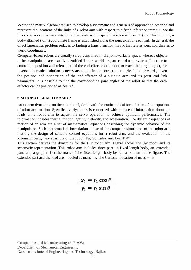
Robot Technology
Computer Aided Manufacturing (2171903)
Department of Mechanical Engineering
Darshan Institute of Engineering and Technology, Rajkot
30
Vector and matrix algebra are used to develop a systematic and generalized approach to describe and
represent the locations of the links of a robot arm with respect to a fixed reference frame. Since the
links of a robot arm can rotate and/or translate with respect to a reference (world) coordinate frame, a
body-attached (joint) coordinate frame is established along the joint axis for each link. In general, the
direct kinematics problem reduces to finding a transformation matrix that relates joint coordinates to
world coordinates.
Computer-based robots are usually servo controlled in the joint-variable space, whereas objects
to be manipulated are usually identified in the world or part coordinate system. In order to
control the position and orientation of the end-effector of a robot to reach the target object, the
inverse kinematics solution is necessary to obtain the correct joint angle. In other words, given
the position and orientation of the end-effector of a six-axis arm and its joint and link
parameters, it is possible to find the corresponding joint angles of the robot so that the end-
effector can be positioned as desired.
6.24 ROBOT-ARM DYNAMICS
Robot-arm dynamics, on the other hand, deals with the mathematical formulation of the equations
of robot-arm motion. Specifically, dynamics is concerned with the use of information about the
loads on a robot arm to adjust the servo operation to achieve optimum performance. The
information includes inertia, friction, gravity, velocity, and acceleration. The dynamic equations of
motion of an arm are a set of mathematical equations describing the dynamic behavior of the
manipulator. Such mathematical formulation is useful for computer simulation of the robot-arm
motion, the design of suitable control equations for a robot arm, and the evaluation of the
kinematic design and structure of the robot [Fu, Gonzalez, and Lee, 1987].
This section derives the dynamics for the r robot arm. Figure shows the -r robot and its
schematic representation. This robot arm includes three parts: a fixed-length body, an. extended
part, and a gripper. Let the mass of the fixed-length body be m1, as shown in the figure. The
extended part and the load are modeled as mass m2. The Cartesian location of mass m1 is

Robot Technology
Computer Aided Manufacturing (2171903)
Department of Mechanical Engineering
Darshan Institute of Engineering and Technology, Rajkot
31
Robot-arm design. A robot-arm designer may want to enter the geometry of a proposed arm design
along with estimates of masses, loads, and so on, and simulate the dynamic performance of the arm.
Path planning. Basic path-control techniques provide a robot programmer with a tool to plan the
desired path for a robot. However, as the robot moves, and speeds and accelerations increase, kinetic
effects may result in an unexpected deviation from the planned path. Path simulation that considers
the dynamic model can be used to develop worst-case estimates of path deviations at high speeds.
Real-time control. It is known that no single choice of servo gains is appropriate to provide the best
performance of a robot. With the dynamic model of the arm.
The knowledge of kinematics and dynamics allows the control of an arm actuator to accomplish a
desired task following a desired path. Trajectory planning and motion control are of considerable
interest and importance, as these issues involve the degree of automation and intelligence of the
robot.
REFERENCES:
James G. Keramas “Robot Technology Fundamentals” India ed. DELMAR CENGAGE
Learning.
Groover and Zimmers “CAD/CAM ” Prentice Hall of India Private Limited.
Mikell P. Groover “Industrial Robotics” 2008 ed. Tata McGraw-Hill.
Saeed B. Niku “Introduction to Robotics” 2009 ed. Prentice Hall of India Private Limited.

IPMS
Computer Aided Manufacturing (2171903)
Department of Mechanical Engineering
Darshan Institute of Engineering and Technology, Rajkot
1
EXPERIMENT NO. 7
AIM: To study about Integrated Production Management System:
7.1 INTRODUCTION
This part of the manual is concerned with the use of computers to manage the production function.
The subject has traditionally been referred to as production planning and control. This function has
been practiced for many years. Attempts to use the computer in production planning date from the
late 1950s and early 1960s. The early attempts were directed toward computerizing the same clerical
procedures which had been done by hand for years. These procedures included preparation of
schedules, shortage lists, inventory lists, and similar documents. During the late 1960s and early
1970s, a few individuals began to recognize the tremendous opportunities provided by the computer
to make fundamental changes in the procedures and organization of production planning and control.
Joseph Orlicky, George Plossl, and Oliver Wight stand out as some of the principal pioneers in these
efforts to modernize and computerize the production management function. MRP (material
requirements planning) was one of the first computerized procedures which significantly improved
the way things were done. Since MRP was first implemented, many additional improvements in
production planning and control have been introduced by taking advantage of the data processing
and computational powers of the computer.
Main objective in this experiment is to describe how computers are utilized to carry out the
production management function in the CAD/CAM age.
7.2 TRADITIONAL PRODUCTION PLANNING AND CONTROL
At least a dozen separate functions can be identified as constituting the cycle of activities in
traditional production planning and control. Organizationally, some of these functions are performed
by departments in the firm other than the production control department. The functions are described
in the following sections.
Forecasting
The forecasting function is concerned with projecting or predicting the future sales activity of the
firm's products. Sales forecasts are often classified according to the time horizon over which they
attempt to estimate. Long-range forecasts look ahead five years or more and are used to guide
decisions about plant construction and equipment acquisition. Intermediate-range forecasts estimate
one or two years in advance and would be used to plan for long-lead-time materials and components.
Short-term forecasts are concerned with a three- to six-month future. Decisions on personnel (e.g.,
new hiring), purchasing, and production scheduling would be based on the short-term forecast.
IPMS
Computer Aided Manufacturing (2171903)
Department of Mechanical Engineering
Darshan Institute of Engineering and Technology, Rajkot
2
Production planning
This is sometimes called aggregate production planning and its objective is to establish general
production levels for product groups over the next year or so. It is based on the sales forecast and is
used to raise or lower inventories, stabilize production over the planning horizon, and allow for the
launching of new products into the company's product line. Aggregate production planning is a
function that precedes the detailed master production schedule.
Process planning
Process planning involves determining the sequence of manufacturing operations required to produce
a certain product and/or its components. Process planning has traditionally been carried out by
manufacturing engineers as a very manual and clerical procedure. The resulting document, prepared
by hand, is called a route sheet and is a listing of the operations and machine tools through which the
part or product must be routed. The term "routing" is sometimes applied to describe the process
planning function.
Estimating
For purposes of determining prices, predicting costs, and preparing schedules, the firm will
determine estimates of the manufacturing lead times and production costs for its products. The
manufacturing lead time is the total time required to process a work part through the factory. The
production costs are the sum of the material costs, labor, and applicable overhead costs needed to
produce the part. These estimates of lead times and costs are based on data contained in the route
sheets, purchasing files, and accounting records.
Master scheduling
The aggregate production plan must be translated into a master schedule which specifies how many
units of each product are to be delivered and when. In turn, this master schedule must be converted
into purchase orders for raw materials, orders for components from outside vendors, and production
schedules for parts made in the shop. These events must be timed and coordinated to allow delivery
of the final product according to the master schedule.
Specifically, the master schedule or master production schedule is a listing of the products to
be produced, when they are to be delivered, and in what quantities. The scheduling periods in the
master schedule are typically months, weeks, or dates. The master schedule must be consistent with
the plant's production capacity. It should not list more quantities of products than the plant is capable
of producing with its given resources of machines and labor.
Requirements planning
Based on the master schedule, the individual components and subassemblies that make up each
product must be planned. Raw materials must be ordered to make the various components. Purchased
parts must be ordered. And all of these items must be planned so that the components and assemblies
are available when needed. This whole task is called requirements planning or material requirements
planning. The term MRP (for material requirements planning) has come into common usage since
the introduction of computerized procedures to perform the massive data processing required to

IPMS
Computer Aided Manufacturing (2171903)
Department of Mechanical Engineering
Darshan Institute of Engineering and Technology, Rajkot
3
accomplish this function. However, the function itself had to be accomplished manually by clerical
workers before computers were used.
Purchasing
The firm will elect to manufacture some components for its products in its own plants. Other
components will be purchased. Deciding between these alternatives is the familiar "make-or-buy"
decision. For the components made in-house, raw materials have to be acquired. Ordering the raw
materials and purchased components is the function of the purchasing department. Materials will be
ordered and the receipt of these items will be scheduled according to the timetable defined during the
requirements planning procedure.
Machine loading and scheduling
Also based on the requirements planning activity is production scheduling. This involves the
assignment of start dates and due dates for the components to be processed through the factory.
Several factors make scheduling complex. First, the number of individual parts and orders to be
scheduled may run into the thousands. Second, each part has its own individual process routing to be
followed. Some parts may have to be routed through dozens of separate machines. Third, the number
of machines in the shop is limited, and the machines are different. They perform different operations
and have different features and capacities.
The total number of jobs to be processed through the factory will typically exceed the number
of machines by a substantial margin. Accordingly, each machine, or work center, will have a queue
of jobs waiting to be processed. Allocating the jobs to work centers is referred to as machine loading.
Allocating the jobs to the entire shop is called shop loading.
Dispatching
Based on the production schedule, the dispatching function is concerned with issuing the individual
orders to the machine operators. This involves giving out order tickets, route sheets, part drawings,
and job instructions. The dispatching function in some shops is performed by the shop foremen, in
other shops by a person called a dispatcher.
Expediting
Even with the best plans and schedules, things go wrong. It is the expediter's job to compare the
actual progress of the order against the production schedule. For orders that fall behind schedule, the
expediter recommends corrective action. This may involve rearranging the sequence in which orders
are to be done on a certain machine, coaxing the foreman to tear down one setup so that another
order can be run, or hand-carrying parts from one department to the next just to keep production
going. There are many reasons why things go wrong in production: parts-in-process have not yet
arrived from the previous department, machine breakdowns, proper tooling not available, quality
problems, and so forth.

IPMS
Computer Aided Manufacturing (2171903)
Department of Mechanical Engineering
Darshan Institute of Engineering and Technology, Rajkot
4
Quality control
The quality control department is responsible for assuring that the quality of the product and its
components meets the standards specified by the designer. This function must be accomplished at
various points throughout the manufacturing cycle. Materials and parts purchased from outside
suppliers must be inspected when they are received. Parts fabricated inside the company must be
inspected, usually several times during processing. Final inspection of the finished product is
performed to test its overall functional and appearance quality.
Shipping and inventory control
The final step in the production control cycle involves shipping the product directly to the customer
or stocking the item in inventory. The purpose of inventory control is to ensure that enough products
of each type are available to satisfy customer demand. Competing with this objective is the desire
that the company's financial investment in inventory be kept at a minimum. Inventory control
interfaces with production control since there must be coordination between the various product's
sales, production, and inventory level. Inventory control is often included within the production
control department.
Figure 7.1 Cycle of activities in a traditional production planning and control
IPMS
Computer Aided Manufacturing (2171903)
Department of Mechanical Engineering
Darshan Institute of Engineering and Technology, Rajkot
5
The inventory control function applies not only to the company's final products. It also
applies to raw materials, purchased components, and work-in-process within the factory. In each
case, planning and control are required to achieve a balance between the danger of too little
inventory (with possible stock outs) and the expense of too much inventory.
The block diagram of Figure 7.1 depicts the relationships among the production planning
and control functions as well as various other functions of the firm, customers, and outside suppliers.
In the diagram, the production planning and control functions are highlighted in bold blocks.
7.3 PROBLEMS WITH TRADITIONAL PRODUCTION PLANNING AND CONTROL
There are many problems that occur during the cycle of activities in the traditional approach to
production planning and control. Many of these problems result directly from the inability of the
traditional approach to deal with the complex and ever-changing nature of manufacturing. The types
of problems commonly encountered in the planning and control of production are the following:
1. Plant capacity problems. Production falls behind schedule due to a lack of labor and
equipment. This results in excessive overtime, delays in meeting delivery schedules, customer
complaints, backordering, and other similar problems.
2. Suboptimal production scheduling. The wrong jobs are scheduled because of a lack of
clear order priorities, inefficient scheduling rules, and the ever-changing status of jobs in the shop.
As a consequence, production runs are interrupted by jobs whose priorities have suddenly increased,
machine setups are increased, and jobs that are on schedule fall behind.
3. Long manufacturing lead times. In an attempt to compensate for problems 1 and 2,
production planners allow extra time to produce an order. The shop becomes overloaded, order
priorities become confused, and the result is excessively long manufacturing lead times.
4. Inefficient inventory control. At the same time that total inventories are too high for raw
materials, work-in-progress, and finished products, there are stock outs that occur on individual items
needed for production. High total inventories mean high carrying costs, while raw material stock outs
mean delays in meeting production schedules.
5. Low work center utilization. This problem results in part from poor scheduling
(excessive product changeovers and job interruptions), and from other factors over which plant
management has limited control (e.g., equipment breakdowns, strikes, reduced demand for products).
6. Process planning not followed. This is the situation in which the regular planned routing
is superseded by an ad hoc process sequence. It occurs, for instance, because of bottlenecks at work
centers in the planned sequence. The consequences are longer setups, improper tooling, and less
efficient processes.
7. Errors in engineering and manufacturing records. Bills of materials are not current,
route sheets are not up to date with respect to the latest engineering changes, inventory records are
inaccurate, and production piece counts are incorrect.
IPMS
Computer Aided Manufacturing (2171903)
Department of Mechanical Engineering
Darshan Institute of Engineering and Technology, Rajkot
6
8. Quality problems. Quality defects are encountered in manufactured components and
assembled products, resulting in rework or scrapped parts, thus causing delays in the shipping
schedule.
7.4 COMPUTER-INTEGRATED PRODUCTION MANAGEMENT SYSTEM
There have been several factors working over the last several decades to cause the evolution of a
more modern and effective approach to the problems of production planning and control cited above.
The most obvious of these factors was the development of the computer, a powerful tool to help
accomplish the vast data processing and routine decision-making chores in production planning that
had previously been done by human beings.
In addition to the computer, there were other factors which were perhaps less dramatic but
equally important. One of these was the increase in the level of professionalism brought to the field
of production planning and control. Production planning has been gradually transformed from what
was largely a clerical function into a recognized profession requiring specialized knowledge and
academic training. Systems, methodologies, and even a terminology have developed to deal with the
problems of this professional field.
Important among the methodologies of production planning and control, and another
significant factor in the development of the field, is operations research. The computer became the
important tool in production planning, but many of the decision-making procedures and software
programs were based on the analytical models provided by operations research. Linear programming,
inventory models, queuing theory, and a host of other techniques have been effectively applied to
problems in production planning and control.
Another factor that has acted as a driving force in the development of better production
planning is increased competition from abroad. Many American firms have lost their competitive
edge in international and even domestic markets. Increasing U.S. productivity is seen as one
important way to improve our competitive position. Better management of the production function is
certainly a key element in productivity improvement.
Finally, a fifth factor is the increase in the complexity of both the products manufactured and
the markets that buy these products. The number of different products has proliferated, tolerances
and specifications are more stringent and customers are more particular in their requirements and
expectations. These changes have placed greater demands on manufacturing firms to manage their
operations more efficiently and responsively.
As a consequence of these factors, companies are gradually abandoning the traditional
approach in favor of what we are calling computer-integrated production management systems.
There are other terms which are used to describe these systems and their major components. IBM
uses the term "communications oriented production information and control system—COPICS" to
identify the group of system elements. George Plossl integrates the various system concepts under
the name "manufacturing control". Computer-Aided Manufacturing International calls its
development effort in this area the "factory management project". Oliver Wight refers to the use of

IPMS
Computer Aided Manufacturing (2171903)
Department of Mechanical Engineering
Darshan Institute of Engineering and Technology, Rajkot
7
MRPII, or manufacturing resource planning, to consolidate the manufacturing, engineering, and
financial functions of the firm into one operating system. All of these terms refer to computerized
information systems designed to integrate the various functions of production planning and control.
Figure 7.2 presents a block diagram illustrating the functions and their relationships in a
computer-integrated production management system. Many of these functions are nearly identical to
their counterparts in-traditional production-planning and control. For example, forecasting,
production planning, the development of the master schedule, purchasing, and other functions appear
the same, in Figures 7.1 and7.2. To be sure, modern computerized systems have been developed to
perform these functions, but the functions themselves remain relatively unchanged. More significant
changes have occurred in the organization and execution of production planning and control through
the implementation of such schemes as MRP, capacity planning, and shop floor control. What
follows is a brief description of some of the recently developed functions in a CIPMS. We will
neglect those functions which are nearly the same as their conventional counterparts. The newer
functions are highlighted in Figure 7.2 by bold blocks.
Figure 7.2 Cycle of activities in a computer-integrated production management system

IPMS
Computer Aided Manufacturing (2171903)
Department of Mechanical Engineering
Darshan Institute of Engineering and Technology, Rajkot
8
7.5 MATERIAL REQUIREMENTS PLANNING:
Material requirements planning is a computational technique that converts the master schedule for
end products into a detailed schedule for the raw material and components used in the end products.
The detailed schedule identifies the quantities of each raw material and component item. It also tells
when each item must be ordered and delivered so as to meet the master schedule for the final
products.
MRP is often considered to be a subset of inventory control. While it is an effective tool for
minimizing unnecessary inventory investment, MRP is also useful in production scheduling and
purchasing of materials.
The concept of MRP is relatively straightforward. What complicates the application of the
technique is the sheer magnitude of the data to be processed. The master schedule provides the
overall production plan for final products in terms of month-by-month or week-by-week delivery
requirements. Each of the products may contain hundreds of individual components. These
components are produced out of raw materials, some of which are common among the components.
For example, several parts may be produced out of the same sheet steel. The components are
assembled into simple subassemblies. Then these subassemblies are put together into more complex
assemblies—and so forth, until the final product is assembled together. Each production and
assembly step takes time. All of these factors must be incorporated into the MRP computations.
Although each separate computation is uncomplicated, the magnitude of all the data to be processed
is so large that the application of MRP is virtually impossible unless carried out on a digital
computer.
7.6 BASIC MRP CONCEPTS
Material requirements planning is based on several basic concepts which are implicit in the
preceding description but not explicitly defined. These concepts are:
1. Independent versus dependent demand
2. Lumpy demand
3. Lead times
4. Common use items
7.6.1 Independent versus dependent demand
This distinction is fundamental to MRP. Independent demand means that demand for a product is
unrelated to demand for other items. End products and spare parts are examples of items whose
demand is independent. Independent demand patterns must usually be forecasted.
Dependent demand means that demand for the item is related directly to the demand for some
other product. The dependency usually derives from the fact that the item is a component of the other
product. Not only component parts, but also raw materials and subassemblies, are examples of items
that are subject to dependent demand.
Whereas demand for the firm's end products must often be forecasted, the raw materials and
IPMS
Computer Aided Manufacturing (2171903)
Department of Mechanical Engineering
Darshan Institute of Engineering and Technology, Rajkot
9
component parts should not be forecasted. Once the delivery schedule for the end products is
established, the requirements for components and raw materials can be calculated directly. For
example, even though the demand for automobiles in a given month can only be forecasted, once that
quantity is established we know that four regular tires will be needed to deliver the car plus one spare
tire.
MRP is the appropriate technique for determining quantities of dependent demand items.
These items constitute the inventory of manufacturing: raw materials, work-in-progress, component
parts, and subassemblies. Accordingly, MRP is a very powerful tool in the planning and control of
manufacturing inventories.
7.6.2 Lumpy demand
In an order point system, the assumption is generally made that the demand for the item in inventory
will occur at a gradual, continuous rate. This assumption is important for developing the mathematical
model to derive the economic lot size formula. In a manufacturing situation, demand for the raw
materials and components of a product will occur in large increments rather than in small, almost
continuous units. The large increments correspond to the quantities needed to make a certain batch of
the final product. When the demand occurs in these large steps, it is referred to by the term “lumpy
demand.'' MRP is the appropriate approach for dealing with inventory situations characterized by lumpy
demand.
7.6.3 Lead times
The lead time for a job is the time that must be allowed to complete the job from start to finish. In
manufacturing there are two kinds of lead times: ordering lead times and manufacturing lead times. An
ordering lead time for an item is the time required from initiation of the purchase requisition to receipt
of the item from the vendor. If the item is a raw material that is stocked by the vendor, the ordering lead
time should be relatively short, perhaps a few weeks. If the item must be fabricated by the vendor, the
lead time may be substantial, perhaps several months.
Manufacturing lead time is the time needed to process the part through the sequence of
machines specified on the route sheet. It includes not only the operation times but also the
nonproductive time that must be allowed.
In MRP, lead times are used to determine starting dates for assembling final products and
subassemblies, for producing component parts, and for ordering raw materials.
7.6.4 Common use items
In manufacturing, the basic raw materials are often used to produce more than one component type.
Also, a given component may be used on more than one final product. For example, the same type of
steel rod stock may be used to produce screws on an automatic screw machine. Each of the screw types
may then be used on several different products. MRP collects these common-use items from different
products to effect economies in ordering the raw materials and manufacturing the components.
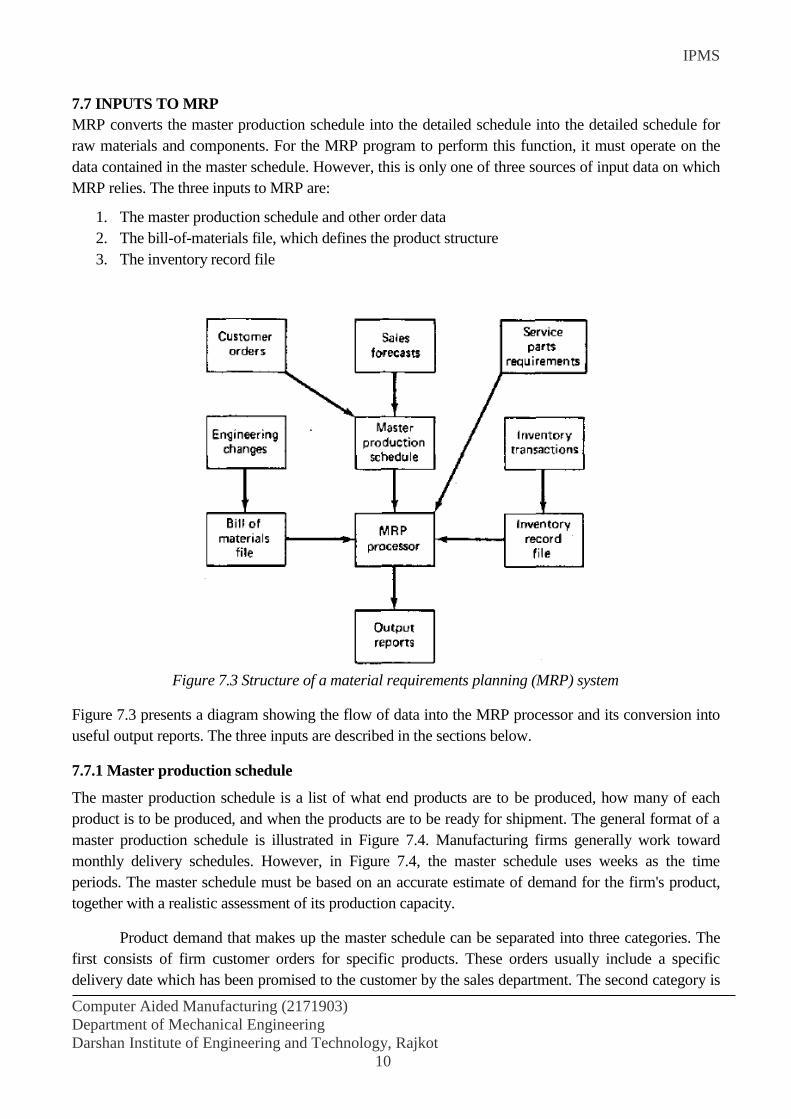
IPMS
Computer Aided Manufacturing (2171903)
Department of Mechanical Engineering
Darshan Institute of Engineering and Technology, Rajkot
10
7.7 INPUTS TO MRP
MRP converts the master production schedule into the detailed schedule into the detailed schedule for
raw materials and components. For the MRP program to perform this function, it must operate on the
data contained in the master schedule. However, this is only one of three sources of input data on which
MRP relies. The three inputs to MRP are:
1. The master production schedule and other order data
2. The bill-of-materials file, which defines the product structure
3. The inventory record file
Figure 7.3 Structure of a material requirements planning (MRP) system
Figure 7.3 presents a diagram showing the flow of data into the MRP processor and its conversion into
useful output reports. The three inputs are described in the sections below.
7.7.1 Master production schedule
The master production schedule is a list of what end products are to be produced, how many of each
product is to be produced, and when the products are to be ready for shipment. The general format of a
master production schedule is illustrated in Figure 7.4. Manufacturing firms generally work toward
monthly delivery schedules. However, in Figure 7.4, the master schedule uses weeks as the time
periods. The master schedule must be based on an accurate estimate of demand for the firm's product,
together with a realistic assessment of its production capacity.
Product demand that makes up the master schedule can be separated into three categories. The
first consists of firm customer orders for specific products. These orders usually include a specific
delivery date which has been promised to the customer by the sales department. The second category is

IPMS
Computer Aided Manufacturing (2171903)
Department of Mechanical Engineering
Darshan Institute of Engineering and Technology, Rajkot
11
forecasted demand. Based on statistical techniques applied to past demand, estimates provided by the
sales staff, and other sources, the firm will generate a forecast of demand for its various product lines.
This forecast may constitute the major portion of the master schedule. The third category is demand for
individual component parts. These components will be used as repair parts and are stocked by the firm's
service department. This third category is often excluded from the master schedule since it does not
represent demand for end products.
Figure 7.4 Master production schedule for products P1 and P2, showing week delivery quantities.
7.7.2 Bill of material file
In order to compute the raw material and component requirements for end products listed in the
master schedule, the product structure must be known. This is specified by the bill of materials,
which is a listing of component parts and subassemblies that make up each product. Putting all these
assembly lists together, we have the bill-of-materials file (BOM).
The structure of an assembled product can be pictured as shown in Figure 6.6. This is a
relatively simple product in which a group of individual components make up two subassemblies,
which in turn make up the product. The product structure is in the form of a pyramid, with lower
levels feeding into the levels above. We can envision one level below that shown in Figure 6.6. This
would consist of the raw materials used to make the individual components. The items at each
successively higher level are called the parents of the items in the level directly below. For example,
subassembly S1 is the parent of components C1, C2, and C3. Product P1 is the parent of
subassemblies S1 and S2.
The product structure must also specify how many of each item is included in its parent. This
is accomplished in Figure 6.5 by the number in parentheses to the right and below each block. For
example, subassembly S1 contains four of component C2 and one each of components C1 and C3.
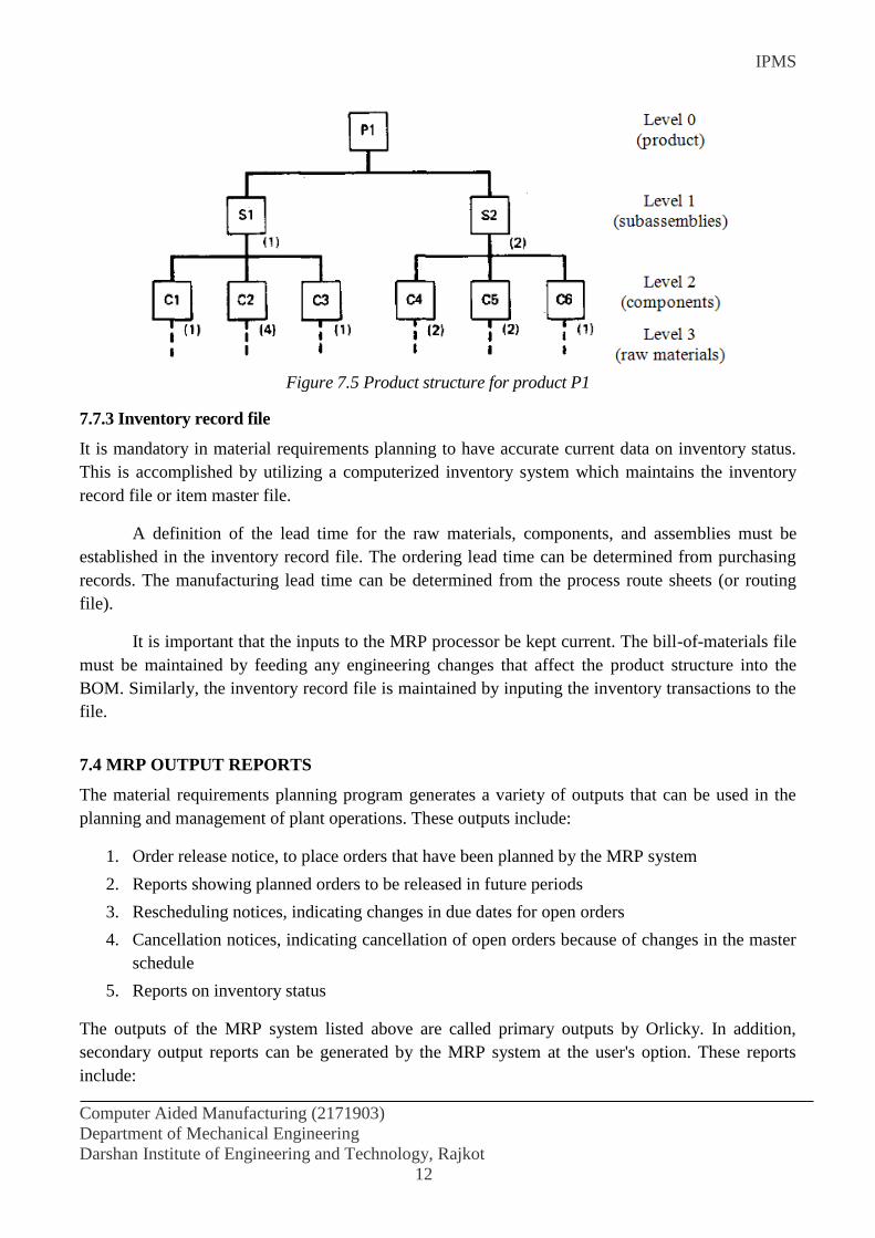
IPMS
Computer Aided Manufacturing (2171903)
Department of Mechanical Engineering
Darshan Institute of Engineering and Technology, Rajkot
12
Figure 7.5 Product structure for product P1
7.7.3 Inventory record file
It is mandatory in material requirements planning to have accurate current data on inventory status.
This is accomplished by utilizing a computerized inventory system which maintains the inventory
record file or item master file.
A definition of the lead time for the raw materials, components, and assemblies must be
established in the inventory record file. The ordering lead time can be determined from purchasing
records. The manufacturing lead time can be determined from the process route sheets (or routing
file).
It is important that the inputs to the MRP processor be kept current. The bill-of-materials file
must be maintained by feeding any engineering changes that affect the product structure into the
BOM. Similarly, the inventory record file is maintained by inputing the inventory transactions to the
file.
7.4 MRP OUTPUT REPORTS
The material requirements planning program generates a variety of outputs that can be used in the
planning and management of plant operations. These outputs include:
1. Order release notice, to place orders that have been planned by the MRP system
2. Reports showing planned orders to be released in future periods
3. Rescheduling notices, indicating changes in due dates for open orders
4. Cancellation notices, indicating cancellation of open orders because of changes in the master
schedule
5. Reports on inventory status
The outputs of the MRP system listed above are called primary outputs by Orlicky. In addition,
secondary output reports can be generated by the MRP system at the user's option. These reports
include:
IPMS
Computer Aided Manufacturing (2171903)
Department of Mechanical Engineering
Darshan Institute of Engineering and Technology, Rajkot
13
1. Performance reports of various types, indicating costs, item usage, actual versus planned lead
times, and other measures of performance
2. Exception reports, showing deviations from schedule, orders that are overdue, scrap, and so
on
3. Inventory forecasts, indicating projected inventory levels (both aggregate inventory as well as
item inventory) in future periods
7.5 BENEFITS OF MRP
There are many advantages claimed for a well-designed, well-managed material requirements
planning system. Among these benefits reported by MRP users are the following.
Reduction in inventory. MRP mainly affects raw materials, purchased components, and work-
in-process inventories. Users claim a 30 to 50% reduction in work-in-process.
Improved customer service. Some MRP proponents claim that late orders are reduced 90%.
Quicker response to changes in demand and in the master schedule.
Greater productivity. Claims are that productivity can be increased by 5 to 30% through
MRP. Labor requirements are reduced correspondingly.
Reduced setup and product changeover costs.
Better machine utilization.
Increased sales and reductions in sales price. These are also claimed as MRP benefits by
some users.
7.6 Manufacturing Resource Planning (MRP II)
Manufacturing resource planning evolved from material requirements planning in the 1980s. It came
to be abbreviated MRP II to distinguish it from the original abbreviation and to indicate that it was
second generation, that is, more than just a material planning system. Manufacturing resource
planning can be defined as a computer-based system for planning, scheduling, and controlling the
materials, resources, and supporting activities needed to meet the master production schedule.
MRP II is a closed-loop system that integrates and coordinates the major functions of the business
involved in production. The term “closed-loop system” means that MRP II incorporates feedback of
data on various aspects of operating performance so that corrective action can be taken in a timely
manner; that is, MRP II includes a shop floor control system.
MRP II can be considered to consist of three major modules: (1) material requirement
planning, or MRP, (2) capacity planning, and (3) shop floor control. MRP accomplishes the planning
functions for materials, parts, and assemblies, based on the master production schedule. In so doing it
also provides a schedule for factory operations. The capacity planning module interacts with the
MRP module to ensure that the schedules created by MRP are feasible. Finally, the shop floor
IPMS
Computer Aided Manufacturing (2171903)
Department of Mechanical Engineering
Darshan Institute of Engineering and Technology, Rajkot
14
control module performs the feedback control function using its factory data collection system to
implement the three phases of order release, order scheduling, and order progress.
Manufacturing resources planning represented an improvement over material requirements
planning because it includes production capacity and shop floor feedback in its computations. But
MRP II was limited to the manufacturing operations of the firm. As further enhancements were made
to the MRP II systems, the trend was to consider all of the operations and functions of the enterprise
rather than manufacturing.
7.7 JIT APPLIED TO FMS
The stockless production concept of just-in-time (JIT) manufacturing, originally pioneered by the
Japanese, is about inventory, but it is much more than inventory reduction. It is about organizing the
production process so that usable parts, both purchased and manufactured, are available on the shop
floor when they are needed- not too late and not too soon.
Throughout the text, emphasis is on material flow and part throughput internal and external to
the cell or FMS. With FMS, sophisticated software handles the part scheduling for each work station,
controls part movement from station to station, handles NC program download to each CNC unit,
and performs a variety of other functions. Ideally, well-implemented and operational JIT techniques
should be a prerequisite to FMS and be in place before a flexible cell or system is installed in order
to follow the "simplify before you automate" rule. Unfortunately, this is not the case in most
companies, as adding cells and systems usually precedes major material flow and inventory
reductions. JIT can be either a cause or an effect of FMS. However, it is difficult to implement FMS
without JIT and achieve the true results of FMS.
FMS forces operational and organizational change in a company. FMS is also a means to a
just-in-time end and can be used in many cases to drive productivity improvement changes like JIT
and group technology through the organization. The training, teamwork, cooperation, planning
effort, and positive attitudes used to implement a cell or system can be carried over and broadened to
undertake implementation of JIT techniques. Installing a cell or system first can provide a seedbed
for planting and leveraging a JIT discipline.
The installation of a cell or system provides the manufacturer with the flexibility to produce
parts in lot sizes as small as one. With an FMS, it is no longer necessary to carry excessively large
inventories or issue high economic order quantities in an attempt to satisfy anticipated customer
demands. The accuracy of marketing's forecast would become less critical since the manufacturer
would now have the option of producing to order. Consequently, the just-in-time philosophy
advocated by a flexible manufacturing system would result in decreased lead times, less work in
process on the shop floor, smaller finished parts inventories, and increased customer satisfaction.
7.8 GT APPLIED TO FMS
The classification and coding associated with GT provides a means by which parts may be easily
selected to load a cell or FMS, if the part classification and coding system is available and
IPMS
Computer Aided Manufacturing (2171903)
Department of Mechanical Engineering
Darshan Institute of Engineering and Technology, Rajkot
15
operational at the time cell or system planning begins. In many instances, however, this is not the
case and the part selection process is done manually. When planning for a cell or system, you are
essentially doing a portion of group technology simply by determining equipment requirements,
deciding which parts go into the cell or FMS, and grouping them accordingly.
An FMS is, in fact, a grouping of machines to process a family of parts within a predefined
range of part feature and characteristic requirements. As mentioned before, an FMS in many cases is
referred to as a cell, depending on system size and how a particular company views its automation
efforts. Given these considerations, it is apparent that an FMS can actually be considered a highly
sophisticated GT manufacturing cell that can produce a wider range of parts and part families than
the traditional GT manufacturing cell.
REFERENCES:
Groover and Zimmers “CAD/CAM ” Prentice Hall of India Private Limited, Page 298.
M.P. Groover “Automation production system and CIM” (2nd Edition), Page 762.