damage identification in frame structures based on fe model updating
TRANSCRIPT

8/8/2019 Damage Identification in Frame Structures Based on FE Model Updating
http://slidepdf.com/reader/full/damage-identification-in-frame-structures-based-on-fe-model-updating 1/13
Ling Yu1
Professor of Structural EngineeringDepartment of Civil Engineering,China Three Gorges University,
Yichang,Hubei 443002, China;
Department of Mechanics and Civil Engineering,Jinan University,
Guangzhou 510632, Chinae-mail: [email protected]
Tao YinAssociate Professor
School of Civil and Architectural Engineering,Wuhan University,
Wuhan 430072, Chinae-mail: [email protected]
Damage Identication in FrameStructures Based on FE ModelUpdatingThis paper proposed a practical damage detection method for frame structures based on
nite element model-updating techniques. An objective function is dened as minimizingthe discrepancies between the experimental and analytical modal parameters (namely,natural frequencies and mode shapes), which is set as a nonlinear least-squares problemwith bound constraints. Unlike the commonly used line-search methods, the trust-regionapproach, a simple yet very powerful concept for minimization, is employed in order tomake the optimization process more robust and reliable. Noting the objective functionmay sometimes be underdetermined for complex structures due to a relatively larger number of potential damaged elements, this paper attempts to propose a simple and convenient solution by expanding the original objective function. Moreover, the relativeweighting scheme between different parts in the objective function is also investigated.One numerical two-story portal frame structure and two laboratory-tested frame struc-tures, including a simple three-story steel frame structure and a more complex framestructure with bolted joints, are all adopted to evaluate the efciency of the proposed technique. Some important issues about the application of the proposed method are alsodiscussed in this paper. DOI: 10.1115/1.4002125
Keywords: damage identication, frame structures, model updating, nonlinear least-squares problem, trust-region method
1 IntroductionA structure may suffer considerable damage without showing
any outward signs of damage during its lifetime. If the potentialdamage could not be detected in time, the accumulated damagemay result in a sudden failure or a fatal disaster of structure,which are very costly in terms of human life and property damage.Therefore, the development of a methodology for the accurate andreliable assessment of structural damage, one crucial step in thestructural health monitoring, is very important to ensure the integ-rity and stability of structures, to reduce the cost of maintenance,and to prevent catastrophic failure 1,2 .
Structural modal parameters, namely, natural frequencies andmode shapes obtained from an experimental modal analysis, cancharacterize the state of a structure. One common approach is toemploy the vibration characteristics of the structure to assess thedamage locations and to estimate the amount of damage. Damageidentication from changes in vibration parameters of a structurehas been a popular research topic in the past few decades 3 .Among the vibration-based damage identication methods, themodel-updating-based methods are often used because the model-updating techniques have provided a rich source of algorithmsthat can be used to identify damage 4 .
The pioneer work related to this eld is based on the optimalmatrix update methods, which directly modify the system matri-ces of the structural nite element FE model to reproduce asclosely as possible the measured response from the data. Baruchand Bar Itzhack 5 modied the structural stiffness matrix basedon the minimal Frobenius norm matrix adjustment technique. Ber-man and Nagy 6 proposed an approach for structural damageidentication by adjusting structural model matrices. Since the
updated system matrices usually lost their physical meaning of theoriginal FE model, Kabe 7 proposed a method updating only thenonzero elements of the stiffness matrix, and Smith and Beattie8 used the quasi-Newton methods to preserve structural connec-
tivity. However, although many efforts had been done, the inher-ent drawback lying in the optimal matrix update methods stillrestricted their real applications. Besides, since the complete modeshapes are needed for these methods, the mode shape expansiontechnique should be adopted, which would aggregate both the
modeling error and experimental noise in the resultant modeshapes.In order to overcome the shortcomings of the optimal matrix
updating methods, a group of methodology, namely, thesensitivity-based updating methods were investigated by many re-searchers. Ricles and Kosmatka 9 presented a sensitivity-basedmatrix approach based on the rst-order Taylor series to identifystructural damage, which is then veried by many numericalsimulations. Hemez and Farhat 10 developed a sensitivity-basedmatrix procedure formulating the sensitivities at the element level,which has the advantage of being computed more efciently thanforming the sensitivities at the global matrix level. Fritzen andJennewein 11 applied a sensitivity-based method to detect struc-tural damage and found that the accuracy of the initial model of astructure is of great importance. Lam et al. 12 proposed amethod for the location detection of connection damage in framestructures and veried the method by both numerical studies of asix-story frame and experimental investigations of a two-storyframe. Zimmerman 13 developed a closed-form solution for thesensitivity of the minimum rank perturbation theory damage vec-tors and calculated stiffness perturbations with respect to errors inthe measured mode shapes or frequency response functions. Thissensitivity allows one to establish condence in damage existence,location, and extent assessment. In 2007, Yin et al. 14 proposeda statistical approach to analyze the inuence of measurementnoise on the sensitivity-based damage detection methods througha typical portal frame structure.
Although the updated matrices have clear physical meaning, the
1Corresponding author.Contributed by the Technical Committee on Vibration and Sound of ASME for
publication in the J OURNAL OF VIBRATION AND ACOUSTICS . Manuscript received January7, 2009; nal manuscript received May 29, 2010; published online August 20, 2010.Assoc. Editor: Jiong Tang.
Journal of Vibration and Acoustics OCTOBER 2010, Vol. 132 / 051007-1Copyright © 2010 by ASME
Downloaded 02 Sep 2010 to 80.66.179.197. Redistribution subject to ASME license or copyright; see http://www.asme.org/terms/Terms_Use.cfm
8/8/2019 Damage Identification in Frame Structures Based on FE Model Updating
http://slidepdf.com/reader/full/damage-identification-in-frame-structures-based-on-fe-model-updating 2/13
8/8/2019 Damage Identification in Frame Structures Based on FE Model Updating
http://slidepdf.com/reader/full/damage-identification-in-frame-structures-based-on-fe-model-updating 3/13
r f i = 1 −
f ai
f t i 5
where N f = N m and the symbol · means the absolute value. r f i
is the ith component in the frequency error vector r f , and sub-scripts t and a denote the tested and analytical data, respectively. r
is an N -dimensional vector indicating the discrepanciesbetween measured and analytical mode shapes corresponding tothe measured DOFs MDOFs only, and thus no mode shape ex-pansion or FE model reduction is required here. It is assumed thatonly N d DOFs are measured. In this paper, r
is expressed asthe difference between 1 and modal assurance criterion MAC30 , given below,
r i = 1 −
t i T
ai 2
t i T
t i
ai T
ai
6
where N = N m, and r
i is the ith component in the error vector r
. It should be pointed out that no scaling or normalization isrequired in the mode shape error provided in Eq. 6 .
The gradient matrix and Hessian matrix of f have a specialstructure, which should be exploited to improve the iterative ef-ciency of the solution procedure for the nonlinear least-squaresproblem. When a truncated Taylor series expansion of the ithcomponent of r at the point k is used and only the rst twoorder items are kept, the following approximate expression can be
obtained: r i r i k + r i k
T − k , i = 1,2, .. . , N 7
Thus, the objective function is given by
f f ˆ =1
2 i=1
N
r i2 =
1
2 i=1
N
r i k + r i k T − k
2
= f k + gk T − k +
1
2 − k
T H k − k 8
where
gk = f k = J k T r k 9
H k = 2 f k J k T J k 10
where g represents the gradient vector of f , H is theHessian matrix of f , and J is the N -by- N Jacobian matrixof r .
2.2 Trust-Region Approach for BCNLS Problem. Thetrust-region algorithm for the BCNLS problem is solved by thefunction lsqnonlin implemented in the optimization toolbox of MATLAB 31 , and the theoretical background of the implementa-tion is only briey reviewed in this section in order to make thispaper self-contained.
Following the MATLAB notations, for any vector x Rn, diag xdenotes an n-by- n diagonal matrix, with the vector x dening thediagonal entries in their natural order. The rst-order optimality, anecessary condition for Eq. 3 , is equivalently stated as
D 2 g = 0, D = diag v 1 / 2 11
where the vector v contains the information of bound con-straints dened as in Ref. 32 . Noting Eqs. 9 and 10 , thescaled modied Newton step d ˆ
k = Dk −1 d k for Eq. 11 can be de-
ned as the solution of the following linear system:
B k d ˆ
k = − g k 12
where
g k = Dk gk = Dk J k T rk 13
B k = Dk H k Dk + diag gk J k
v Dk J k T J k Dk + diag J k
T rk J k v 14
and J v is the Jacobian matrix of v 29 .In the neighborhood of a local minimizer, if the positive scalar
k is large enough, the Newton step dened by Eq. 12 is asolution to a quadratic approximation model subjected to an ellip-tical constraint as
min d ˆ R N
d ˆ = g k T d ˆ + 1
2 d ˆ T B k d ˆ : d ˆ
k 15
The above quadratic model can be solved by the trust-region ap-proach 28 efciently, a simple yet very powerful concept for
minimization. Moreover, the minimization restricts the trust-region subproblem to a two-dimensional subspace V ; thus, thecomputational effort can be signicantly saved especially for alarge-scale optimization problem. V = v 1 , v 2 . v 1 is in the direc-tion of the gradient g . v 2 is either an approximate Newton direc-tion or a direction of a negative curvature, which can force theglobal convergence and achieve a fast local convergence by aproper selection of subspace V .
Therefore, instead of the model described in Eq. 15 , anothertwo-dimensional quadratic approximation model subjected to anelliptical constraint is redened as
min d ˆ R2
d ˆ = g k T d ˆ + 1
2 d ˆ T B k d ˆ : d ˆ
k 16
where the two-dimensional gradient vector g k
and the correspond-ing Hessian matrix B
k can be given by g k = V k T g k and B
k
= V k T B
k V k , accordingly.A basic framework for the trust-region approach in this paper is
described as follows: i formulate the above two-dimensionaltrust-region subproblem in Eq. 16 ; ii solve the subproblem todetermine the scaled trial step d ˆ
k , then d ˆ k = V k d ˆ
k , and d k = Dk d ˆ k ;
iii if f k + d k f k , then k +1 = k + d k ; and iv update thetrust-region size . The four steps are repeated until convergence.The convergence criterion is as follows: 1 the change in relativefunction value is less than a predened tolerance, i.e., f k − f k −1 / f k −1 ; or 2 the rst-order optimality is satised,i.e., D k
2 g k , and H k is a positive-denite matrix atthe same time.
The essential idea behind the trust-region approach is to adjustthe trust-region size for ensuring a sufcient decrease in theobjective function; i.e., the reduction in objective function shouldbe at least a fraction of the reduction of the quadratic modelwithin the trust region following certain rules 33 .
2.3 Weighting Strategy. The components of the objectivefunction vector r can be weighted separately based on theirrelative importance. The following procedure is for the weightednonlinear least-squares problem,
f =1
2Wr 2 =
1
2 i=1
N
wir i 2 =1
2
W f r f
W r
2
17
W = diag w , W f = diag w f , W = diag w , w = w f T ,w
T T
18
where W , W f , and W are all diagonal weighting matrices. w f andw are N m-dimensional weighting vectors of the frequency andmode shape errors in objective function, respectively. Generally,the relative magnitudes between w f and w are unknown. Withoutloss of generality, it is assumed that w
= w
i , w f = w f
i , i= 1 , 2 , . . . , N m, and the weight ratio WR dened by WR= w
/ w
f can be utilized to represent the relative importance be-tween the frequency and mode shape errors within the above ob- jective function. The larger the WR value is, the more importantthe mode shape part in the objective function is.
Journal of Vibration and Acoustics OCTOBER 2010, Vol. 132 / 051007-3
Downloaded 02 Sep 2010 to 80.66.179.197. Redistribution subject to ASME license or copyright; see http://www.asme.org/terms/Terms_Use.cfm
8/8/2019 Damage Identification in Frame Structures Based on FE Model Updating
http://slidepdf.com/reader/full/damage-identification-in-frame-structures-based-on-fe-model-updating 4/13
2.4 Expansion of Objective Function. It must be pointed outthat there is an inherent limitation for directly implementing theMATLAB function lsqnonlin to the box constrained nonlinear least-squares problem. That is this function does not solve underdeter-mined systems. In other words, it requires that the number of equations i.e., the number of components of the objective func-tion vector be at least as great as the number of unknown vari-ables. Otherwise, this function will only be used with the boundsignored in the underdetermined case. Specically, for the methodproposed in this paper, the condition N = 2 N m N should be sat-ised see Eq. 4 . In such a situation, the number of unknown
parameters should be restricted to be relatively smaller. There-fore, in order to meet the requirement of N N , a simple andconvenient expansion process for the initial objective functionvector is proposed, and the general form of the vector-valuedfunction r is given by
r = r f
T , r T T , for N = 2 N m N
r f T , r
T , r eT T , for N = 2 N m N
19
where r e is an N e-dimensional vector, representing the expansionpart of the objective function vector r . In order to simplify theanalysis, the condition fact that all components of the expansionvector r e are equal constants is investigated in this paper. In sucha situation, the dimension of the expansion vector N e is conve-niently set to be TOE 2 N m. Times of expansion TOE is a posi-
tive integer denoting the times of expansion of the objective func-tion, and it can be employed to investigate the inuence of thedimension of expansion vector on damage detection results. Theamplitude of the expansion vector is represented by a non-negative scalar multiplier, namely, MULT. Thus, the expansionvector takes the form r e =MULT I N e 1, and I N e 1 is an N e-dimensional vector with all elements equal to 1.
3 Numerical Simulations
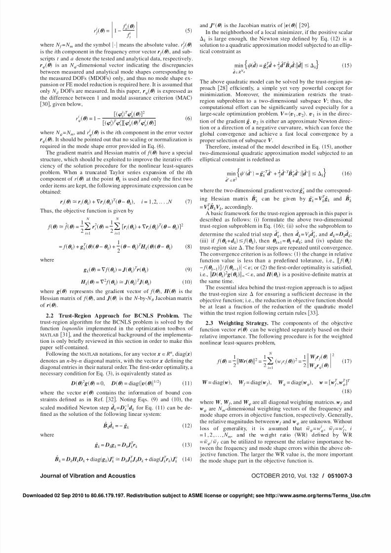
3.1 Finite Element Model of Portal Frame. In order to il-lustrate the application of the proposed method in the structuraldamage detection, a set of simulations was carried out for a two-story portal frame in Ref. 12 , in which the semirigid effects of beam-column and column-base connections are neglected. The FEmodel of the frame is modeled by 18 two-dimensional frame el-ements with equal length. The numbering of both nodes and ele-ments is shown in Fig. 1. The sectional and material properties of the frame are listed in Table 1.
The rst six natural frequencies for the healthy structure arelisted in Table 2. Both the 16 measured DOFs and their corre-sponding directions are also listed in the table. The effect of ex-perimental noise is considered here. As an example, NL= 1%, 10% means that the natural frequencies and mode shapeshave a measurement noise level NL with standard deviations of 1% and 10%, respectively. Herein, a relatively lower frequencynoise level adopted here is due to the fact that the accuracy of experimental natural frequencies is usually much higher than thatof mode shapes in a real situation.
3.2 Cases Considered. For convenience, 20% reduction inelemental Young’s modulus is used to simulate damage of stiff-ness loss, and two damage cases shown in Table 3 are considered.Case 1 D14 is a single-damage case, in which only element 14has 20% stiffness reduction. Case 2 D2-8-17 is a multidamagecase, where elements 2, 8, and 17 are set as damaged elementssimultaneously, each with 20% stiffness reduction. The elementaldamage extent EDE is used instead of the ESP to convenientlyshow the damage status of each element, and EDE= 1− ESP.Since EDE is a vector, the residual sum of squares RSS of EDEis conveniently employed to measure the proximity of the identi-ed and actual damages.
3.3 Parameter Study for Damage Identication. There aresome control parameters such as TOE, MULT, and WR in theproposed method. In order to investigate the inuence of theseparameters on the damage detection results, the parameter studiesare carried out one by one in the following parts.
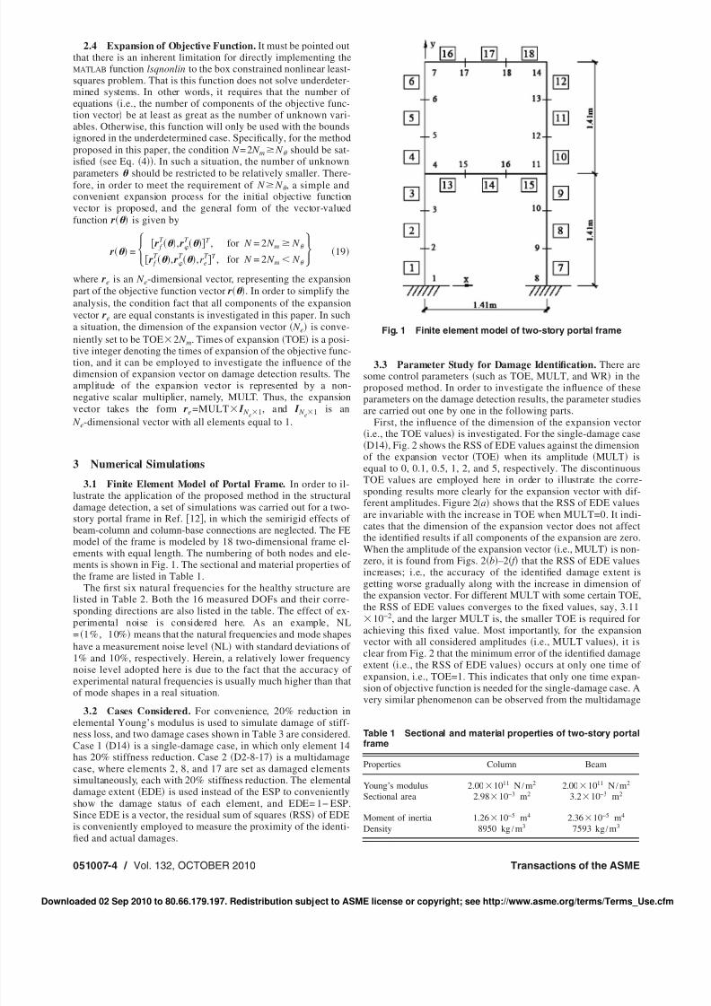
First, the inuence of the dimension of the expansion vectori.e., the TOE values is investigated. For the single-damage caseD14 , Fig. 2 shows the RSS of EDE values against the dimension
of the expansion vector TOE when its amplitude MULT isequal to 0, 0.1, 0.5, 1, 2, and 5, respectively. The discontinuousTOE values are employed here in order to illustrate the corre-sponding results more clearly for the expansion vector with dif-ferent amplitudes. Figure 2 a shows that the RSS of EDE valuesare invariable with the increase in TOE when MULT=0. It indi-
cates that the dimension of the expansion vector does not affectthe identied results if all components of the expansion are zero.When the amplitude of the expansion vector i.e., MULT is non-zero, it is found from Figs. 2 b –2 f that the RSS of EDE valuesincreases; i.e., the accuracy of the identied damage extent isgetting worse gradually along with the increase in dimension of the expansion vector. For different MULT with some certain TOE,the RSS of EDE values converges to the xed values, say, 3.11
10−2 , and the larger MULT is, the smaller TOE is required forachieving this xed value. Most importantly, for the expansionvector with all considered amplitudes i.e., MULT values , it isclear from Fig. 2 that the minimum error of the identied damageextent i.e., the RSS of EDE values occurs at only one time of expansion, i.e., TOE=1. This indicates that only one time expan-sion of objective function is needed for the single-damage case. Avery similar phenomenon can be observed from the multidamage
Fig. 1 Finite element model of two-story portal frame
Table 1 Sectional and material properties of two-story portalframe
Properties Column Beam
Young’s modulus 2.00 1011 N / m2 2.00 1011 N / m2
Sectional area 2.98 10−3 m2 3.2 10−3 m2
Moment of inertia 1.26 10−5 m4 2.36 10−5 m4
Density 8950 kg / m3 7593 kg / m3
051007-4 / Vol. 132, OCTOBER 2010 Transactions of the ASME
Downloaded 02 Sep 2010 to 80.66.179.197. Redistribution subject to ASME license or copyright; see http://www.asme.org/terms/Terms_Use.cfm
8/8/2019 Damage Identification in Frame Structures Based on FE Model Updating
http://slidepdf.com/reader/full/damage-identification-in-frame-structures-based-on-fe-model-updating 5/13
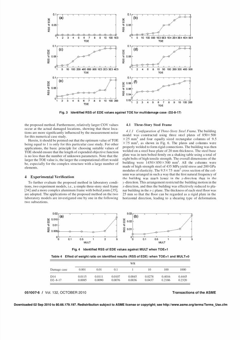
case D2-8-17 , shown in Fig. 3.Second, based on the above discussions, the dimension of ex-
pansion vector should be equal to the length of the original objec-tive function vector i.e., TOE=1 for this case study. In such asituation TOE=1 , the MULT values are set to be the same asbefore i.e., 0, 0.1, 0.5, 1, 2, and 5, respectively , and the error of identied damage extent i.e., the RSS of EDE values is com-pared in Fig. 4 for both the single-damage and multidamage casesin order to investigate the inuence of the amplitude of the expan-sion vector on the accuracies of identied damage. It is clear fromthis gure that the RSS of EDE values for both damage casesincreases gradually, showing that 0 can be considered as a suitablevalue for MULT. That is to say, only zero elements are needed inthe expansion vector.
Finally, it should be noted that in the above discussions, it isassumed that the relative importance between the frequency andmode shape errors are equivalent i.e., the weight ratio, WR=1without loss of generality. Although WR can also be set to othervalues, the conclusions about choosing the suitable TOE andMULT values are the same as above. In order to investigate theinuence of WR on the accuracy of identied damages separately,the values of TOE and MULT are kept to be their relatively opti-
mal values derived above i.e., TOE=1 and MULT=0 , and thecorresponding results for both single-damage and multidamagecases are shown in Table 4. It is very clear from this table thatWR=1 gives the best identication results for both damage cases.It indicates that the relative importance for both the natural fre-quency and the mode shape errors in the objective function shouldbe equivalent.
It is concluded from the above parameter studies of the two-story portal frame that the identied results are relatively optimumwhen TOE=1, MULT=0, and WR=1. In the following section,these optimal parameters are used to identify the damage of theframe structure for both single-damage and multidamage casesunder noised condition.
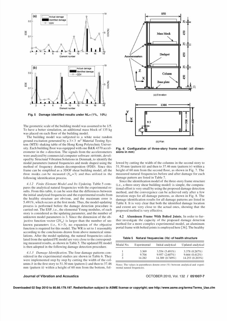
3.4 Damage Identication Results of the Portal Frame. Inorder to investigate the uncertainties associated with the identiedresults, the coefcient of variation COV is adopted. The identi-ed EDE values for both single-damage and multidamage cases,together with corresponding COV values, are all illustrated in Fig.5. It is very clear from this gure that the damage location and thecorresponding extent are well identied for both the single-damage and multidamage cases under noised condition by using
Table 2 Natural frequencies „Hz…and MDOF of health frame
Item
Modal number
1 2 3 4 5 6
Health 39.89 122.51 278.49 304.07 379.37 440.04MDOFnode and direction 2 x, 3 x, 4 x, 5 x, 6 x, 7 x, 9 x, 10 x, 11 x, 12 x, 13 x, 14 x, 15 y, 16 y, 17 y, 18 y
Table 3 Cases considered for two-story portal frame
Case No.
Descriptions of each case
Damaged element s MULT WR
1 14 0, 0.1, 0.5, 1, 2, 5 0, 0.001, 0.01, 0.1, 1, 10, 100, 1000, inf 2 2, 8, 17
Fig. 2 Identied RSS of EDE values against TOE for single-damage case „D14 …
Journal of Vibration and Acoustics OCTOBER 2010, Vol. 132 / 051007-5
Downloaded 02 Sep 2010 to 80.66.179.197. Redistribution subject to ASME license or copyright; see http://www.asme.org/terms/Terms_Use.cfm
8/8/2019 Damage Identification in Frame Structures Based on FE Model Updating
http://slidepdf.com/reader/full/damage-identification-in-frame-structures-based-on-fe-model-updating 6/13
the proposed method. Furthermore, relatively larger COV valuesoccur at the actual damaged locations, showing that these loca-tions are more signicantly inuenced by the measurement noisefor this numerical case study.
Herein, it should be pointed out that the optimum value of TOEbeing equal to 1 is only for this particular case study. For otherapplications, the basic principle for choosing suitable values of TOE should ensure that the length of expended objective functionis no less than the number of unknown parameters. Note that thelarger the TOE value is, the larger the computational effort wouldbe, especially for the complex structure with a large number of elements.
4 Experimental VericationTo further evaluate the proposed method in laboratory condi-
tions, two experiment models, i.e., a simple three-story steel frame34 and a more complex aluminum frame with bolted joints 35 ,
are adopted. The applications of the proposed method on the twolaboratory models are investigated one by one in the followingtwo subsections.
4.1 Three-Story Steel Frame
4.1.1 Conguration of Three-Story Steel Frame . The buildingmodel was constructed using three steel plates of 850 500
25 mm 3 and four equally sized rectangular columns of 9.575 mm 2, as shown in Fig. 6. The plates and columns were
properly welded to form rigid connections. The building was thenwelded on a steel base plate of 20 mm thickness. The steel baseplate was in turn bolted rmly on a shaking table using a total of eight bolts of high tensile strength. The overall dimensions of thebuilding were 1450 850 500 mm 3. All the columns weremade of high strength steel of 435 MPa yield stress and 200 GPamodulus of elasticity. The 9.5 75 mm 2 cross section of the col-umn was arranged in such a way that the rst natural frequency of
the building was much lower in the x-direction than in the y-direction. This arrangement restricted the building motion in the x-direction, and thus the building was effectively reduced to pla-nar building in the x- z plane. The thickness of each steel oor was25 mm so that the oor can be regarded as a rigid plate in thehorizontal direction, leading to a shearing type of deformation.
Fig. 3 Identied RSS of EDE values against TOE for multidamage case „D2-8-17 …
Fig. 4 Identied RSS of EDE values against MULT when TOE=1
Table 4 Effect of weight ratio on identied results „RSS of EDE …when TOE=1 and MULT=0
Damage case
WR
0.001 0.01 0.1 1 10 100 1000
D14 0.0115 0.0111 0.0107 0.0045 0.0278 0.4016 0.4445D2–8-17 0.0085 0.0090 0.0076 0.0036 0.0437 0.2186 0.2320
051007-6 / Vol. 132, OCTOBER 2010 Transactions of the ASME
Downloaded 02 Sep 2010 to 80.66.179.197. Redistribution subject to ASME license or copyright; see http://www.asme.org/terms/Terms_Use.cfm
8/8/2019 Damage Identification in Frame Structures Based on FE Model Updating
http://slidepdf.com/reader/full/damage-identification-in-frame-structures-based-on-fe-model-updating 7/13
The geometric scale of the building model was assumed to be 1/5.To have a better simulation, an additional mass block of 135 kgwas placed on each oor of the building model.
The building model was subjected to a white noise randomground excitation generated by a 3 3 m2 Material Testing Sys-tem MTS shaking table of the Hong Kong Polytechnic Univer-sity. Each building oor was equipped with one B&K 4370 accel-erometer in the x-direction. The signals from the accelerometerswere analyzed by commercial computer software ARTEMIS , devel-oped by Structural Vibration Solutions in Denmark, to identify themodal parameters natural frequencies and mode shapes using themethod of frequency domain decomposition FDD . Since thisframe can be simplied as a 3DOF shear building model, all thethree modes can be measured N m =3 and thus utilized in thefollowing identication process.
4.1.2 Finite Element Model and Its Updating . Table 5 com-pares the analytical natural frequencies with the experimental re-sults. From this table, it can be seen that the differences betweenthe initial analytical frequencies and the experimental results fromthe healthy structure are obvious, and the maximum error is5.491%, which occurs at the rst mode. Thus, the model-updatingprocess is performed before the damage detection procedure iscarried out. The ESP, i.e., the elemental Young modulus, of eachstory is considered as the updating parameter, and the number of unknown model parameters is 3. Since the dimension of the ob- jective function vector 2 N m is larger than the number of un-
known parameters i.e., 6 3 , no expansion of the objectivefunction is required for this model. The WR is set to 1 reasonablyaccording to the conclusions drawn from above numerical simu-lations. After the model updating, the natural frequencies calcu-lated from the updated FE model are very close to the correspond-ing measured results, as shown in Table 5. The updated FE modelis then adopted in the following damage detection procedure.
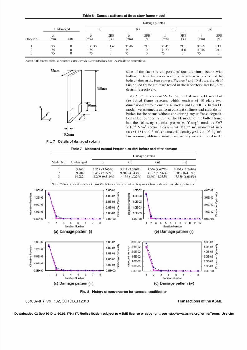
4.1.3 Damage Identication . The four damage patterns con-sidered in the experimental studies are shown in Table 6. Theywere implemented step by step by cutting the width of the col-umns b in the rst story to 51.30 mm pattern i and then to 37.46mm pattern ii within a height of 60 mm from the bottom, fol-
lowed by cutting the width of the columns in the second story to51.30 mm pattern iii and then to 37.46 mm pattern iv within aheight of 60 mm from the second oor, as shown in Fig. 7. Themeasured natural frequencies before and after damage for eachdamage pattern are listed in Table 7.
Since the identication model of the three-story frame structurei.e., a three-story shear building model is simple, the computa-
tional effort is very small by using the proposed damage detectionmethod, and the convergence can be achieved only after a fewiteration steps for all damage patterns, as shown in Fig. 8. Thedamage identication results for all damage patterns are listed inTable 8. It is very clear that both the identied damage locationand extent are very close to the actual ones, showing that theproposed method is very effective.
4.2 Aluminum Frame With Bolted Joints. In order to fur-ther investigate the capacity of the proposed damage detection
method for a more complex experimental model, an aluminumportal frame with bolted joints is employed here 36 . The healthy
Fig. 5 Damage identied results under NL= „1%, 10% …
Fig. 6 Conguration of three-story frame model „all dimen-sions in mm …
Table 5 Natural frequencies „Hz…of health structure
Modal No. Experimental Initial analytical Updated analytical
1 3.369 3.554 5.491% 3.378 0.267%2 9.704 9.957 2.607% 9.664 0.412%3 14.282 14.389 0.749% 14.253 0.203%
Notes: The values in parentheses denote error % between analytical and experi-mental natural frequencies.
Journal of Vibration and Acoustics OCTOBER 2010, Vol. 132 / 051007-7
Downloaded 02 Sep 2010 to 80.66.179.197. Redistribution subject to ASME license or copyright; see http://www.asme.org/terms/Terms_Use.cfm
8/8/2019 Damage Identification in Frame Structures Based on FE Model Updating
http://slidepdf.com/reader/full/damage-identification-in-frame-structures-based-on-fe-model-updating 8/13
state of the frame is composed of four aluminum beams withhollow rectangular cross sections, which were connected bybolted joints at the four corners. Figures 9 and 10 show a sketch of this bolted frame structure tested in the laboratory and the jointdesign, respectively.
4.2.1 Finite Element Model . Figure 11 shows the FE model of the bolted frame structure, which consists of 40 plane two-dimensional frame elements, 40 nodes, and 120 DOFs. In this FEmodel, we assumed a uniform constant stiffness and mass distri-bution for the beams without considering any stiffness degrada-tion at the four corner joints. The FE model of the bolted frame
has the following material properties: Young’s modulus E = 71010 N / m2, section area A=2.241 10−4 m2, moment of iner-
tia I =1.431 10−8 m4, and material density =2.7 103 kg / m3.Furthermore, additional masses m1 and m2 were included in the
Table 6 Damage patterns of three-story frame model
Story No.
Undamaged
Damage patterns
i ii iii iv
bmm SRE
bmm
SRE%
bmm
SRE%
bmm
SRE%
bmm
SRE%
1 75 0 51.30 11.6 37.46 21.1 37.46 21.1 37.46 21.12 75 0 75 0 75 0 51.30 11.6 37.46 21.13 75 0 75 0 75 0 75 0 75 0
Notes: SRE denotes stiffness reduction extent, which is computed based on shear building assumptions.
Fig. 7 Details of damaged column
Table 7 Measured natural frequencies „Hz…before and after damage
Modal No. Undamaged
Damage patterns
i ii iii iv
1 3.369 3.259 3.265% 3.113 7.599% 3.076 8.697% 3.003 10.864%2 9.704 9.485 2.257% 9.302 4.143% 9.192 5.276% 9.082 6.410%3 14.282 14.209 0.511% 14.136 1.022% 13.660 4.355% 13.330 6.666%
Notes: Values in parentheses denote error % between measured natural frequencies from undamaged and damaged frames.
Fig. 8 History of convergence for damage identication
051007-8 / Vol. 132, OCTOBER 2010 Transactions of the ASME
Downloaded 02 Sep 2010 to 80.66.179.197. Redistribution subject to ASME license or copyright; see http://www.asme.org/terms/Terms_Use.cfm
8/8/2019 Damage Identification in Frame Structures Based on FE Model Updating
http://slidepdf.com/reader/full/damage-identification-in-frame-structures-based-on-fe-model-updating 9/13
FE model of the aluminum frame, where m1 =0.052 kg for thecorner joints and m2 = 0.0318 kg for the bolts used to x the softsprings for the experimental modal test under free-free boundarycondition.
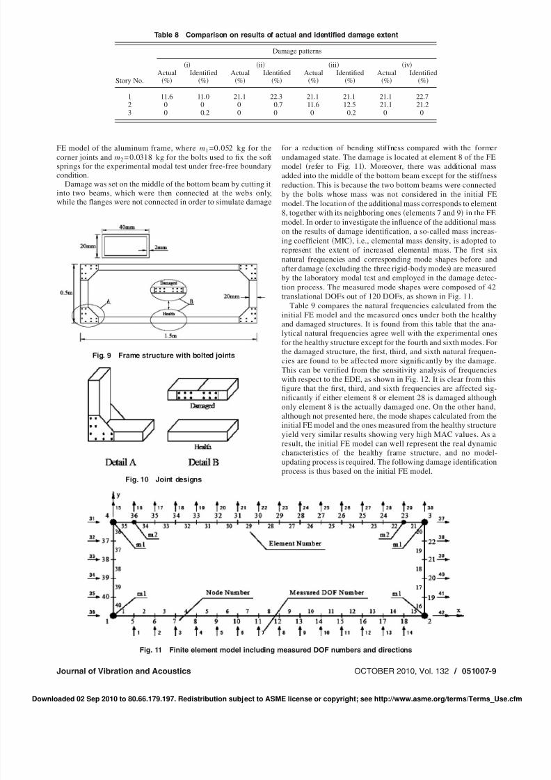
Damage was set on the middle of the bottom beam by cutting itinto two beams, which were then connected at the webs only,while the anges were not connected in order to simulate damage
for a reduction of bending stiffness compared with the formerundamaged state. The damage is located at element 8 of the FEmodel refer to Fig. 11 . Moreover, there was additional massadded into the middle of the bottom beam except for the stiffnessreduction. This is because the two bottom beams were connectedby the bolts whose mass was not considered in the initial FEmodel. The location of the additional mass corresponds to element8, together with its neighboring ones elements 7 and 9 in the FEmodel. In order to investigate the inuence of the additional masson the results of damage identication, a so-called mass increas-ing coefcient MIC , i.e., elemental mass density, is adopted torepresent the extent of increased elemental mass. The rst sixnatural frequencies and corresponding mode shapes before andafter damage excluding the three rigid-body modes are measuredby the laboratory modal test and employed in the damage detec-tion process. The measured mode shapes were composed of 42translational DOFs out of 120 DOFs, as shown in Fig. 11.
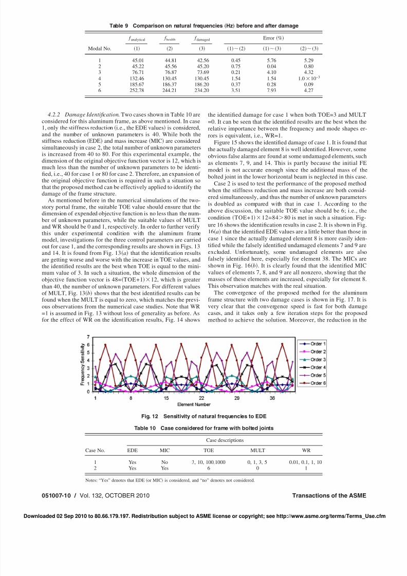
Table 9 compares the natural frequencies calculated from theinitial FE model and the measured ones under both the healthyand damaged structures. It is found from this table that the ana-lytical natural frequencies agree well with the experimental onesfor the healthy structure except for the fourth and sixth modes. Forthe damaged structure, the rst, third, and sixth natural frequen-cies are found to be affected more signicantly by the damage.This can be veried from the sensitivity analysis of frequencieswith respect to the EDE, as shown in Fig. 12. It is clear from thisgure that the rst, third, and sixth frequencies are affected sig-nicantly if either element 8 or element 28 is damaged although
only element 8 is the actually damaged one. On the other hand,although not presented here, the mode shapes calculated from theinitial FE model and the ones measured from the healthy structureyield very similar results showing very high MAC values. As aresult, the initial FE model can well represent the real dynamiccharacteristics of the healthy frame structure, and no model-updating process is required. The following damage identicationprocess is thus based on the initial FE model.
Table 8 Comparison on results of actual and identied damage extent
Story No.
Damage patterns
i ii iii ivActual
%Identied
%Actual
%Identied
%Actual
%Identied
%Actual
%Identied
%
1 11.6 11.0 21.1 22.3 21.1 21.1 21.1 22.72 0 0 0 0.7 11.6 12.5 21.1 21.23 0 0.2 0 0 0 0.2 0 0
Fig. 9 Frame structure with bolted joints
Fig. 10 Joint designs
Fig. 11 Finite element model including measured DOF numbers and directions
Journal of Vibration and Acoustics OCTOBER 2010, Vol. 132 / 051007-9
Downloaded 02 Sep 2010 to 80.66.179.197. Redistribution subject to ASME license or copyright; see http://www.asme.org/terms/Terms_Use.cfm
8/8/2019 Damage Identification in Frame Structures Based on FE Model Updating
http://slidepdf.com/reader/full/damage-identification-in-frame-structures-based-on-fe-model-updating 10/13
4.2.2 Damage Identication . Two cases shown in Table 10 areconsidered for this aluminum frame, as above mentioned. In case1, only the stiffness reduction i.e., the EDE values is considered,and the number of unknown parameters is 40. While both thestiffness reduction EDE and mass increase MIC are consideredsimultaneously in case 2, the total number of unknown parametersis increased from 40 to 80. For this experimental example, thedimension of the original objective function vector is 12, which ismuch less than the number of unknown parameters to be identi-ed, i.e., 40 for case 1 or 80 for case 2. Therefore, an expansion of the original objective function is required in such a situation sothat the proposed method can be effectively applied to identify thedamage of the frame structure.
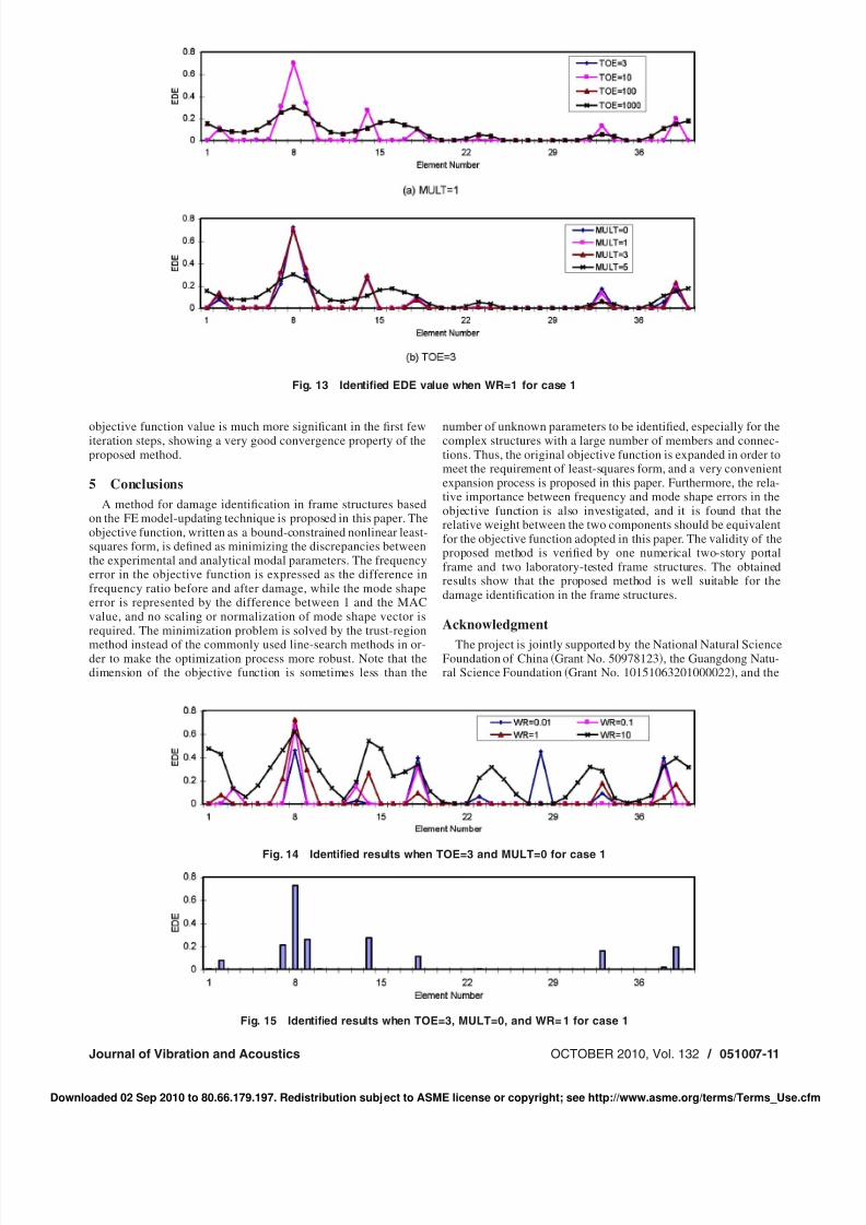
As mentioned before in the numerical simulations of the two-story portal frame, the suitable TOE value should ensure that thedimension of expended objective function is no less than the num-ber of unknown parameters, while the suitable values of MULTand WR should be 0 and 1, respectively. In order to further verifythis under experimental condition with the aluminum framemodel, investigations for the three control parameters are carriedout for case 1, and the corresponding results are shown in Figs. 13and 14. It is found from Fig. 13 a that the identication resultsare getting worse and worse with the increase in TOE values, andthe identied results are the best when TOE is equal to the mini-mum value of 3. In such a situation, the whole dimension of theobjective function vector is 48= TOE+1 12, which is greaterthan 40, the number of unknown parameters. For different valuesof MULT, Fig. 13 b shows that the best identied results can be
found when the MULT is equal to zero, which matches the previ-ous observations from the numerical case studies. Note that WR=1 is assumed in Fig. 13 without loss of generality as before. Asfor the effect of WR on the identication results, Fig. 14 shows
the identied damage for case 1 when both TOE=3 and MULT=0. It can be seen that the identied results are the best when therelative importance between the frequency and mode shapes er-rors is equivalent, i.e., WR=1.
Figure 15 shows the identied damage of case 1. It is found thatthe actually damaged element 8 is well identied. However, someobvious false alarms are found at some undamaged elements, suchas elements 7, 9, and 14. This is partly because the initial FEmodel is not accurate enough since the additional mass of thebolted joint in the lower horizontal beam is neglected in this case.
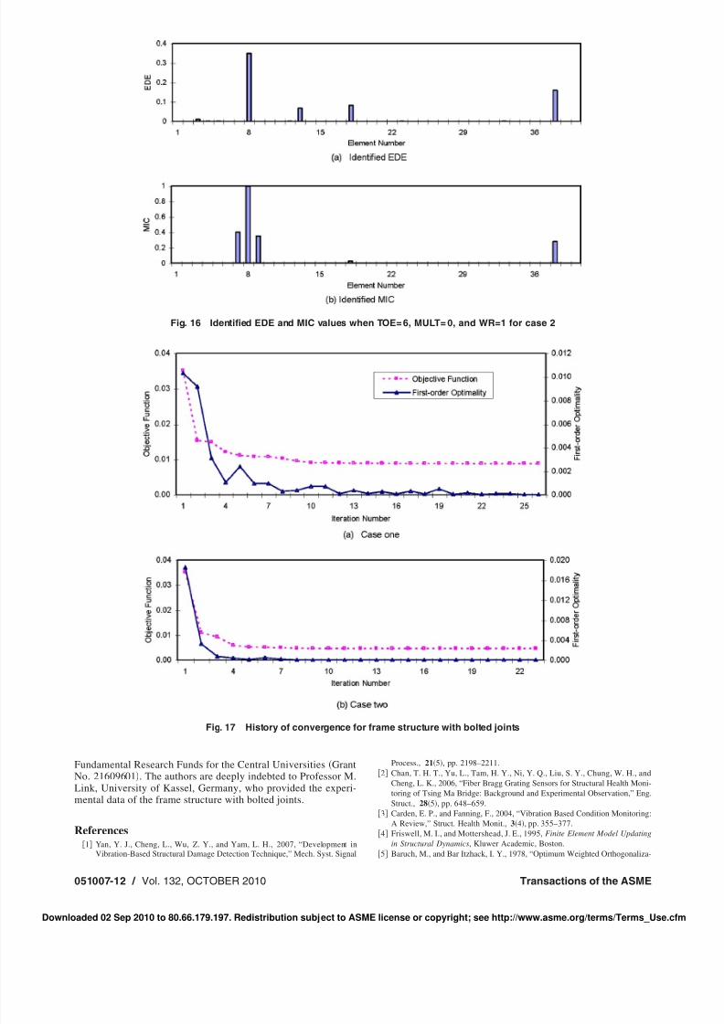
Case 2 is used to test the performance of the proposed methodwhen the stiffness reduction and mass increase are both consid-ered simultaneously, and thus the number of unknown parametersis doubled as compared with that in case 1. According to theabove discussion, the suitable TOE value should be 6; i.e., thecondition TOE+1 12=84 80 is met in such a situation. Fig-ure 16 shows the identication results in case 2. It is shown in Fig.16 a that the identied EDE values are a little better than those incase 1 since the actually damaged element 8 is more easily iden-tied while the falsely identied undamaged elements 7 and 9 areexcluded. Unfortunately, some undamaged elements are alsofalsely identied here, especially for element 38. The MICs areshown in Fig. 16 b . It is clearly found that the identied MICvalues of elements 7, 8, and 9 are all nonzero, showing that themasses of these elements are increased, especially for element 8.This observation matches with the real situation.
The convergence of the proposed method for the aluminumframe structure with two damage cases is shown in Fig. 17. It isvery clear that the convergence speed is fast for both damagecases, and it takes only a few iteration steps for the proposedmethod to achieve the solution. Moreover, the reduction in the
Table 9 Comparison on natural frequencies „Hz…before and after damage
Modal No.
f analytical f health f damaged Error %
1 2 3 1 2 1 3 2 3
1 45.01 44.81 42.56 0.45 5.76 5.292 45.22 45.56 45.20 0.75 0.04 0.803 76.71 76.87 73.69 0.21 4.10 4.324 132.46 130.45 130.45 1.54 1.54 1.0 10−3
5 185.67 186.37 186.20 0.37 0.28 0.096 252.78 244.21 234.20 3.51 7.93 4.27
Fig. 12 Sensitivity of natural frequencies to EDE
Table 10 Case considered for frame with bolted joints
Case No.
Case descriptions
EDE MIC TOE MULT WR
1 Yes No 3, 10, 100,1000 0, 1, 3, 5 0.01, 0.1, 1, 102 Yes Yes 6 0 1
Notes: “Yes” denotes that EDE or MIC is considered, and “no” denotes not considered.
051007-10 / Vol. 132, OCTOBER 2010 Transactions of the ASME
Downloaded 02 Sep 2010 to 80.66.179.197. Redistribution subject to ASME license or copyright; see http://www.asme.org/terms/Terms_Use.cfm
8/8/2019 Damage Identification in Frame Structures Based on FE Model Updating
http://slidepdf.com/reader/full/damage-identification-in-frame-structures-based-on-fe-model-updating 11/13
objective function value is much more signicant in the rst fewiteration steps, showing a very good convergence property of theproposed method.
5 ConclusionsA method for damage identication in frame structures based
on the FE model-updating technique is proposed in this paper. Theobjective function, written as a bound-constrained nonlinear least-squares form, is dened as minimizing the discrepancies betweenthe experimental and analytical modal parameters. The frequencyerror in the objective function is expressed as the difference infrequency ratio before and after damage, while the mode shapeerror is represented by the difference between 1 and the MACvalue, and no scaling or normalization of mode shape vector isrequired. The minimization problem is solved by the trust-regionmethod instead of the commonly used line-search methods in or-der to make the optimization process more robust. Note that thedimension of the objective function is sometimes less than the
number of unknown parameters to be identied, especially for thecomplex structures with a large number of members and connec-tions. Thus, the original objective function is expanded in order tomeet the requirement of least-squares form, and a very convenientexpansion process is proposed in this paper. Furthermore, the rela-tive importance between frequency and mode shape errors in theobjective function is also investigated, and it is found that therelative weight between the two components should be equivalentfor the objective function adopted in this paper. The validity of theproposed method is veried by one numerical two-story portalframe and two laboratory-tested frame structures. The obtainedresults show that the proposed method is well suitable for thedamage identication in the frame structures.
Acknowledgment
The project is jointly supported by the National Natural ScienceFoundation of China Grant No. 50978123 , the Guangdong Natu-ral Science Foundation Grant No. 10151063201000022 , and the
Fig. 13 Identied EDE value when WR=1 for case 1
Fig. 14 Identied results when TOE=3 and MULT=0 for case 1
Fig. 15 Identied results when TOE=3, MULT=0, and WR= 1 for case 1
Journal of Vibration and Acoustics OCTOBER 2010, Vol. 132 / 051007-11
Downloaded 02 Sep 2010 to 80.66.179.197. Redistribution subject to ASME license or copyright; see http://www.asme.org/terms/Terms_Use.cfm
8/8/2019 Damage Identification in Frame Structures Based on FE Model Updating
http://slidepdf.com/reader/full/damage-identification-in-frame-structures-based-on-fe-model-updating 12/13
Fundamental Research Funds for the Central Universities GrantNo. 21609601 . The authors are deeply indebted to Professor M.Link, University of Kassel, Germany, who provided the experi-mental data of the frame structure with bolted joints.
References1 Yan, Y. J., Cheng, L., Wu, Z. Y., and Yam, L. H., 2007, “Development in
Vibration-Based Structural Damage Detection Technique,” Mech. Syst. Signal
Process., 21 5 , pp. 2198–2211.2 Chan, T. H. T., Yu, L., Tam, H. Y., Ni, Y. Q., Liu, S. Y., Chung, W. H., and
Cheng, L. K., 2006, “Fiber Bragg Grating Sensors for Structural Health Moni-toring of Tsing Ma Bridge: Background and Experimental Observation,” Eng.Struct., 28 5 , pp. 648–659.
3 Carden, E. P., and Fanning, F., 2004, “Vibration Based Condition Monitoring:A Review,” Struct. Health Monit., 3 4 , pp. 355–377.
4 Friswell, M. I., and Mottershead, J. E., 1995, Finite Element Model Updatingin Structural Dynamics , Kluwer Academic, Boston.
5 Baruch, M., and Bar Itzhack, I. Y., 1978, “Optimum Weighted Orthogonaliza-
Fig. 16 Identied EDE and MIC values when TOE= 6, MULT= 0, and WR=1 for case 2
Fig. 17 History of convergence for frame structure with bolted joints
051007-12 / Vol. 132, OCTOBER 2010 Transactions of the ASME
Downloaded 02 Sep 2010 to 80.66.179.197. Redistribution subject to ASME license or copyright; see http://www.asme.org/terms/Terms_Use.cfm
8/8/2019 Damage Identification in Frame Structures Based on FE Model Updating
http://slidepdf.com/reader/full/damage-identification-in-frame-structures-based-on-fe-model-updating 13/13