damage evaluation with multi-scale failure analysis using … · 2012-03-08 · multi-scale failure...
TRANSCRIPT

Jung-sun Park*Jung-Sun Park1, Myung-Jun Kim2, Hae-Kyu Hur3, Min-sung Kim3
1 School of Aerospace and Mechanical Engineering, Korea Aerospace University, Koyang, Republic of Korea 2 Graduate School, Korea Aerospace University, Koyang, Republic of Korea 3 Agency for Defense Development, Daejeon, Republic of Korea
Damage Evaluation with Multi-scale Failure Analysis
using Material Degradation Model based on SIFT

1. Introduction
4. Multi-scale Failure Prediction of Composite Plate
6. Conclusions
3. Micro-mechanical Modification
Damage Evaluation with Multi-scale Failure Analysis using Material Degradation Model based on SIFT
2. Strain-based Failure Theory of Composite
5. Damage Evaluation using Property Degradation Model

3
1. Introduction

Mechanical Approach for Failure of Composite Materials
Over the years, the macro-mechanicalapproaches have been applied for thefailure of composite materials.
Practical failure mechanism ofcomposite materials cannot bepredicted in the macroscopic level.
4
Micro-level of the composite failurecriteria were proposed by Hashin andSun.
In recent years, SIFT is proposed byGosse that a more efficient method topredict the failure of micro-level.
Failure criteria for composite materials are divided into macroscopic and microscopic approach.

Fiber
Failure
Fiber / Matrix
Interaction
Failure Mode
Matrix
Failure
Damage initiation is caused by dilatational and distortional deformations in fiber or matrix phase.
Micro-mechanical approach is required for the failure analysis of composite materials.
In this study, Strain Invariant Failure Theory was applied as the microscopic criterion.
Need of the Micro-mechanical Approach for Composite Failure
5
Fiber breakage Fiber pullout Fiber buckling failure
Matrix cracking
Delamination Fiber/Matrix debonding
Failure modes are separated into the fiber failure, matrix failure and fiber/matrix interaction.

Multi-scale failure approach based on SIFT
6
Static analysis for composite laminatewith macroscopic loading
Macro-scale
Determination of mesoscopic behavior (σ/ε in each ply )
Loading
Laminate Layer
Micro-mechanical modification by strain amplification factors(Calculating effective strain invariants)
Microscopic failure analysis by strain invariant failure criterion
Micro-scaleRVE
Strain component in each plyMicro-mechanical failure mode

2. Strain-based Failure Theory of Composite

Strain Invariant Failure Theory (SIFT)
Strain Invariant Failure Theory was proposed by Gosse in 2001.
SIFT defines the failure characteristic of each fiber and matrix by using the volumetric strain and the equivalent strain.
8
Volumetric strain (sum of strain invariants) Dilatational (volumetric) deformation Equivalent strain (von-Mises strain) Distortional (deviatoric) deformation
Dilatational deformation Distortional deformation
Change of volume
Change of shape
vε eqvε

Volumetric strain
9
The strain invariants can be defined as functions of three principal strains from cubic characteristic equation of strain tensor.
3 21 2 3 0J J Jε ε ε− + − =
1 1 2 3J ε ε ε= + +
2 1 2 2 3 3 1J ε ε ε ε ε ε= + +
3 1 2 3J ε ε ε=
1 2 3( , , )f ε ε ε
Cubic characteristic equation
Actually, the volumetric strain is defined by the sum of each strain invariant.
In practice, J1 is considered as significant component of the volumetric strain.
1 2 3 1v J J J Jε = + + ≈
Strain invariants
Most significant component of the volumetric strain

Equivalent strain (von-Mises strain)
10
'3 ' ' '2 3 0J Jε ε− − =
( )' 2 2 2 2 2 22
1 1[( ) ( ) ( ) ]
6 4xx yy yy zz zz xx xy yz zxJ ε ε ε ε ε ε ε ε ε= − + − + − − + +
( )2 2 23' ' ' ' ' ' '1
4xx yy zz xy yz zx xx yz yy zx zz xyJ ε ε ε ε ε ε ε ε ε ε ε ε= + − − −
: Cubic characteristic equation of deviatoric strain( )'ε ε ε= −
The equivalent strain (von-Mises strain) is defined as a function of the second invariant of the deviatoric strain tensor.
The deviatoric strain invariants are obtained from cubic characteristic equation of the deviatoric strains tensor.
Deviatoric strain invariants
2 2 21 2 1 3 2 30.5[( ) ( ) ( ) ]ε ε ε ε ε ε= − + − + −'
23vm Jε =

Strain Invariant Failure Criterion
11
The effective strain invariants are calculated through the micro-mechanical modification.
- Effective first invariant of strain- Effective equivalent strain (von-Mises strain)
Failure will occur at either the fiber or the matrix phases if any of the effective strain invariants (J1, εvm) exceed the critical value.
1 0 ,J ≥ 1 1criticalJ J≥
1 0 ,J < criticalvm vmε ε≥
For matrix
criticalvm vmε ε≥
Failure criterion in SIFT for matrix and fiber
For fiber

Micromechanical Modification
3. Micromechanical Modification

Concept of Strain Amplification Factor
13
Homogenized lamina solution provides an average state of strain representing boththe fiber and matrix phase at the same point in space.
In order to perform the microscopic analysis, a method of the micromechanical modification is required to amplified the average state of strain.
In micro-scale analysis , the mechanical strain amplification factor is very important parameter for connecting the micro-level and macro-level strain tensor.
{ } [ ]{ }ij total ij mechMε ε=( / )
ijij
ij oM
L Lε
=∆
:
:
:
ij
ij
o
local strain
L prescribd unit displacement
L initial length of RVE which is parallel with loading direction
ε
∆

Concept of Strain Amplification Factor
14
Strain amplification factor is calculated by finite element analysis for micro-mechanical block model.
The micromechanical block is called the RVE (Representative Volume Element) which is explicit model of fiber and matrix.
The type of RVE is divided by fiber packing arrays, namely square, hexagonal and diamond.

Micromechanical Block Modeling
15
In order to obtain the strain amplification factor of IM7/K3B composite materials,finite element model of the RVE was generated by MSC.Patran.
The single cell model of square array type was used to perform the microscopic analysis.
Mechanical Property
Fiber (IM7)
Matrix (K3B)
Composite Lamina
E11 [GPa] 303 3.31 177.075
E22 [GPa] 15.2 3.31 10.403
G12 [GPa] 9.65 1.23 6.105
G23 [GPa] 6.32 1.23 6.105
ν12 0.2 0.35 0.2947
ν23 0.2 0.35 0.2947
RVE (Representative Volume Element) Mechanical properties of IM7/K3B
Vf=60 %

Boundary Condition of Micromechanical block
16
RVE is given prescribed unit displacement in three case of normal deformation for one of the faces.
Also, the other five faces are constrained by symmetric condition.
Definition of boundary conditions
Mechanical strain amplification factor Boundary conditions
M11 ε11 = 1, ε22 = ε33 = γ12 = γ13 = γ23 = 0(longitudinal direction)
M22 ε22 = 1, ε11 = ε33 = γ12 = γ13 = γ23 = 0(transverse direction)
M33 ε33 = 1, ε11 = ε22 = γ12 = γ13 = γ23 = 0(transverse direction)
Transverse direction (M33)
Transverse direction (M22)
Longitudinal direction (M11)

17
10 points were selected in the single cell for the extraction of local strain values.
- Matrix region : M00 (Interstitial location), M01-M02 (Inter-fiber location), M1-M3 (Fiber/matrix interface)
- Fiber region : F1-F3 (Fiber/matrix interface), F4 (Center of fiber)
Selected points to extract the local strains
Extracting the Strain Amplification Factor

Matrix Phase
Fiber Phase
18
M11 for longitudinal direction are all 1.0 at any selected points in fiber and matrix. M22 and M33 are equal due to rotational symmetry for square array.
The result of the strain amplification factor, M22
Extracting the Strain Amplification Factor
Maximum strain amplification factors for each directionRegion Strain invariant M11 M22 M33
Matrix phase Case of J1 1 2.61523 2.61523
Case of εmvm 1 2.72389 2.72389
Fiber phase Case of εfvm 1 0.77291 0.77291

4. Multi-scale Failure Prediction of Composite Plate

20
In order to perform the failure analysis, the strain tensor was extracted forcomposite open-hole plate model through the finite element analysis.
- The materials of composite plate is IM7(graphite) / K3B(epoxy).- The stacking sequence is [45°/90°/-45°/0°]s
Static analysis of Composite One-hole Plate Model
Finite element model of composite open-hole plate
FEMmodeling
y-symmetry
x-symm
etry
21
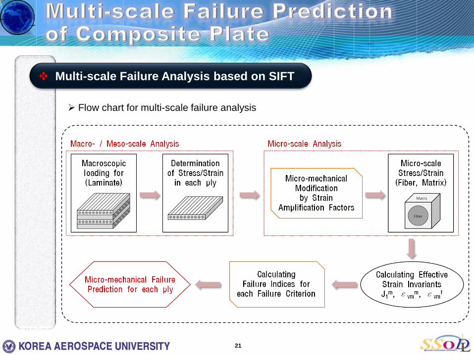
Flow chart for multi-scale failure analysis
Multi-scale Failure Analysis based on SIFT

22
X Component (Longitudinal direction) Y Component (Transverse direction)
X Component (Longitudinal direction) Y Component (Transverse direction)
Strain distribution of composite plate Layer 1 (45°)
Layer 2 (90°)

23
X Component (Longitudinal direction) Y Component (Transverse direction)
X Component (Longitudinal direction) Y Component (Transverse direction)
Strain distribution of composite plate Layer 3 (-45°)
Layer 4 (0°)

Effective Strain invariants
24
The strain components were amplified by the strain amplification factors. And then, the effective strain invariants (J1, εvm) were calculated.
Failure analysis of Composite Tensile Plate Model
2 2 211 1 22 2 11 1 33 3 22 2 33 30.5[( ) ( ) ( ) ]vm M M M M M Mε ε ε ε ε ε ε= − + − + −
11 22 331 1 2 3J M M Mε ε ε= + +
Critical strain invariants for graphite/epoxy laminated composite (IM7/K3B) were used experimental data from reference [2].
Critical invariant Value Laminate stacking sequence Failure Mode
J1-crm 0.0274 [90]10 Matrix / Dilatational
εvm-crm 0.103 [10]10 Matrix / Distortional
εvm-crf 0.0182 [0]10 Fiber / Distortional

25
Failure indices for each layer [45°/90°/-45°/0°]s
J1 failure is dominant
J1 failure is dominant
J1 failure is dominant
εvmf failure
is dominant
Layer 1 (45°) Layer 2 (90°)
Layer 4 (0°)Layer 3 (-45°)

26
Comparing with existing theories (Maximum strain, Tsai-Wu, Hashin, Sun failure criterion)
Similar tendency was confirmed from the distribution of failure index.
Layer 1 (45°) Layer 2 (90°)
Layer 4 (0°)Layer 3 (-45°)

5. Damage Evaluation of Composite Plate using Property Degradation Model

28
Micro-mechanical failure modes can be determined with Strain invariant failure criteria.
Micro-mechanical Failure Modes
Constituent Loading Condition Failure Mode Failure Criterion
Fiber
Tensile(Longitudinal)
Fiber fracture
εvmf
Fiber pullout
Compression (Longitudinal)
Fiber kinking
Fiber buckling
MatrixTensile Matrix cracking (J1≥0) J1
Compression Matrix compression failure (J1<0) εvmm
Fiber/Matrix Tensile / Compression Fiber/Matrix shearing (de-bonding) failure εvmm
Matrix cracking(Tens. / Comp.)
Fiber fracture Fiber pullout Fiber/Matrix shearing (de-bonding) failure

29
Material degradation models were defined for each failure mode.
- Matrix failure :
- Fiber failure :
- Fiber/matrix shearing :
User-subroutine (USDFLD) in ABAQUS/CAE was used to degrade the material properties.
Material Property Degradation Model
Material State(Failure Mode) Elastic Properties Field variable
#1Field variable
#2Field variable
#3
No failure Ex Ey vxy Gxy 0 0 0Matrix failure Ex 0 0 Gxy 1 0 0Fiber failure 0 Ey 0 Gxy 0 1 0Fiber/matrix shearing failure Ex Ey 0 0 0 0 1Matrix & Fiber failure 0 0 0 Gxy 1 1 0Matrix failure & Fib/mtx shear Ex 0 0 0 1 0 1Fiber failure & Fib/mtx shear 0 Ey 0 0 0 1 1All failure modes 0 0 0 0 1 1 1
1 0 ,J ≥ 1 1m m
crJ J −≥
1 0 ,J < m mvm vm crε ε −≥
f fvm vm crε ε −≥
m mvm vm crε ε −≥
0y xyE ν= =
0x xyE ν= =
0xy xyGν = =
Property
Degradation

30
Flow chart for damage evaluation using property degradation models
Damage Evaluation using Property Degradation Model

Displacement loading
X-symmetry
Y-symmetry
Critical Region
31
Composite open-hole plate model was generated by ABAQUS/CAE. Static analysis was performed using by property degradation models.
- The materials of composite plate is IM7/K3B.- The stacking sequence is [(-45°/+45°)6]s.
Composite Open-hole Plate Model
L = 2.0 in
W = 0.5 in
d = 0.25 in
t = 0.135 in (total)

Damage for Matrix failure mode>> Strain Invariant : J1 (Tensile) / εvm
m (Compression)
Increment 1 Increment 2 Increment 3 Increment 4 Increment 5
Increment 6 Increment 7 Increment 8
Damage distribution of composite plate
Critical location
Increment 9 Increment 10
Failure regionis extended
Local failure occurs

Increment 1 Increment 2 Increment 3 Increment 4 Increment 5
Increment 6 Increment 7 Increment 8 Increment 9 Increment 10
Damage for Fiber failure mode>> Strain Invariant : εvm
f (Tensile / Compression)
Damage distribution of composite plate

Increment 1 Increment 2 Increment 3 Increment 4 Increment 5
Increment 6 Increment 7 Increment 8 Increment 9 Increment 10
Damage for Fiber/matrix shearing failure mode>> Strain Invariant : εvm
m (Tensile / Compression)
Damage distribution of composite plate

6. Conclusions

The strain amplification factors were obtained from the result of micro-mechanical analysis for RVE model.
Micro-mechanical modification was performed for macroscopic strains of composite plate model.
The strain-based failure analysis was performed by using the SIFT.
The result of failure analysis was verified by comparing with existing theories.
36
Damage Evaluation with Multi-scale Failure Analysis using Material Degradation Model based on SIFT
Micro-mechanical progressive damage was evaluated for composite plate using the material property degradation models.

Power DesignThank you very much !Thank you very much !Thank you very much !
Q & A