d6.1 first report on the specification of the metro/core
TRANSCRIPT

D6.1 First Report on the Specification of the Metro/Core Node Architecture
Dissemination Level: PU
• Dissemination level:
PU = Public,
RE = Restricted to a group specified by the consortium (including the Commission Services), PP = Restricted to other programme participants (including the Commission
Services), CO = Confidential, only for members of the consortium (including the
Commission Services)
Ref. Ares(2014)275202 - 05/02/2014

FP7 – ICT – GA 318137 2 DISCUS
Abstract:
This document reports the preliminary outcome resulting from Task T6.1, “metro/core node architecture design”. In order to derive the functions required at DISCUS metro/core (MC) node, a set of network services are identified first, covering the applications that are expected to be carried out through both long-reach passive optical network (LR-PON) and optical flat core in DISCUS architecture. Then the initial design of the overall DISCUS metro/core node architecture is presented. It contains the functions for different layers supporting the specified DISCUS network services, such as optical switching, optical transport, optical line terminal towards LR-PON dealing with time and wavelength division multiplexing, Layer2/3 switching as well as the corresponding control plane interfaces. A case study based on a preliminary MC node dimension model is presented for a specific deployment scenario to show the scalability of the node design. The deliverable also includes the background bases for the different architectural aspects (such as resiliency, quality of service, open access, optical power budget, energy efficiency, and cost) as well as some preliminary performance assessments. Based on these, several challenges and issues have been identified to be further investigated during the remainder of the project in order to enhance the initial design of DISCUS MC node architecture.

FP7 – ICT – GA 318137 3 DISCUS
Authors:
Name Affiliation
Jiajia Chen KTH
Mozhgan Mahloo KTH
Lena Wosinska KTH
Giuseppe Ferraris TI
Marco Schiano
TI
Laura Serra TI
M. Pilar Ruiz Aragon TID
Felipe Jimenez Arribas TID
Julio Montalvo Garcia TID
Thomas Pfeiffer ALUD
Rich Jensen POLATIS
Nick Parsons POLATIS
Alan Hill TCD
Nattapong Kitsuwan TCD
Marco Ruffini TCD
David Payne TCD
Giuseppe Talli TYNDALL
Internal reviewers:
Name Affiliation
Harald Rohde COR
Nick Doran ASTON
Due date: 31st August, 2013

FP7 – ICT – GA 318137 4 DISCUS
COPYRIGHT
© Copyright by the DISCUS Consortium. The DISCUS Consortium consists of: Participant Number
Participant organization name Participant org. short name
Country
Coordinator 1 Trinity College Dublin TCD Ireland Other Beneficiaries 2 Alcatel-Lucent Deutschland AG ALUD Germany 3 Coriant GmbH COR Germany 4 Telefonica Investigacion Y Desarrollo SA TID Spain 5 Telecom Italia S.p.A TI Italy 6 Aston Universtity ASTON United
Kingdom 7 Interuniversitair Micro-Electronica
Centrum VZW IMEC Belgium
8 III V Lab GIE III-V France 9 University College Cork, National
University of Ireland, Cork Tyndall & UCC Ireland
10 Polatis Ltd POLATIS United Kingdom
11 atesio GMBH ATESIO Germany 12 Kungliga Tekniska Hoegskolan KTH Sweden
This document may not be copied, reproduced, or modified in whole or in part for any purpose without written permission from the DISCUS Consortium. In addition to such written permission to copy, reproduce, or modify this document in whole or part, an acknowledgement of the authors of the document and all applicable portions of the copyright notice must be clearly referenced. All rights reserved.

FP7 – ICT – GA 318137 5 DISCUS
TABLE OF CONTENTS
1 INTRODUCTION .................................................................................................................... 7
1.1 A BRIEF OVERVIEW OF DISCUS METRO/CORE NODE ....................................................... 7
1.2 OUTLINE OF THE DELIVERABLE ................................................................................................ 8
2 SPECIFICATIONS OF DISCUS SUPPORTED NETWORK SERVICES ............. 10
2.1 END USER-ORIENTED NETWORK SERVICES ..........................................................................11
2.1.1 Residential Services ............................................................................................................. 15
2.1.2 Business and Cloud Services ........................................................................................... 16
2.1.3 Mobile backhauling (2G, 3G, LTE) ............................................................................ 18
2.2 CORE-ORIENTED NETWORK SERVICES ..................................................................................21
2.2.1 Photonic Layer Network Services ................................................................................ 21
2.2.2 Packet Transport Layer Network Services ............................................................. 25
2.3 QOS PRELIMINARY REQUIREMENTS .......................................................................................28
3 OVERALL DISCUS METRO/CORE NODE DESIGN ............................................... 31
3.1 LAYER 1: OPTICAL SWITCHING AND TRANSPORT FUNCTIONS .....................................31
3.1.1 Optical Space Switching Technology ......................................................................... 32
3.1.2 Optical Transport Functions .......................................................................................... 36
3.2 LAYER 1/2: OLT...........................................................................................................................42
3.2.1 The architecture of the metro/access network and of the Access Node ... 42
3.2.2 State-of-the-art CO equipment for TDM-PON .................................................... 43
3.2.3 OLT architecture for TWDM/DWDM-PON ......................................................... 44
3.3 LAYER 2/3: MPLS/MPLS-TP SWITCHING ...........................................................................50
3.4 CONTROL PLANE ..........................................................................................................................59
3.4.1 A broad view of the DISCUS control plane ............................................................ 59
3.4.2 Scenarios and functionalities implemented in the DISCUS OpenFlow
based control plane. ................................................................................................................................... 62
3.5 PRELIMINARY METRO/CORE NODE DIMENSIONING MODEL AND CASE STUDY .......68
3.5.1 Configurable parameters .................................................................................................. 71
3.5.2 Modeling and dimensioning variables ....................................................................... 73
3.5.3 Network structure ................................................................................................................ 77
3.5.4 Optical switch structure and dimensioning ............................................................ 78
3.5.5 Initial results from dimensioning model................................................................... 82
3.5.6 Dimensioning Summary ....................................................................................................... 85
4 ARCHITECTURAL ASPECTS .......................................................................................... 87
4.1 RESILIENCY ...................................................................................................................................87
4.1.1 Reliability of 192x192 optical switch matrix .......................................................... 87
4.1.2 Reliability performance of Clos Switch .................................................................... 87
4.2 DOWNSTREAM QUALITY OF SERVICE ...................................................................................90
4.2.1 Upstream QoS and Bandwidth Fairness .................................................................. 91
4.2.2 Downstream QoS & Scheduling into Multiple LR-PONs ............................... 93
4.2.3 Current Downstream QoS Solutions .......................................................................... 93
4.2.4 The Problem of Hierarchical Scheduling ................................................................. 98
4.2.5 A Non-Hierarchical Scheduling Approach ............................................................. 99
4.2.6 Further Challenges & Issues ....................................................................................... 100
4.3 DESIGN FOR OPEN ACCESS .................................................................................................... 102
4.4 OPTICAL POWER BUDGET ...................................................................................................... 105
4.5 ENERGY EFFICIENCY ............................................................................................................... 109
4.6 COST ............................................................................................................................................. 111
5 CONCLUSIONS .................................................................................................................. 113

FP7 – ICT – GA 318137 6 DISCUS
6 ABBREVIATIONS.............................................................................................................. 115
7 REFERENCES ..................................................................................................................... 119
8 APPENDIX I ......................................................................................................................... 121

FP7 – ICT – GA 318137 7 DISCUS
1 Introduction
DISCUS aims to design an economic and sustainable network architecture that can deliver ubiquitous high speed broadband access to all users independent of their geographical location. This architecture builds on the concept of Long-Reach Passive Optical Network (LR-PON) in the access, and a flat backbone partitioned into optical transparent islands. The network nodes located at the edge of core segment directly connect LR-PON access segment. They are the only place to provide electronic packet processing interface between access and core segments. It enables access capability to the core edge and hence completely removes the metro network, which is one of the major features of the DISCUS architecture. On the other hand, in contrast to the core or metro nodes in today’s network, these specific DISCUS nodes should be able to efficiently deal with all types of network services including both user and core oriented applications, which introduces a great challenge on scalable and flexible node architecture design.
The goal of this deliverable is to identify a list of network services that DISCUS architecture should support as well as reporting the updates on design of the DISCUS node, which was initially depicted in D2.1. With consideration of different architectural aspects, the challenges and issues have been pointed out to be worked through during the remainder of the project in order to improve the node architecture accordingly.
1.1 A brief overview of DISCUS Metro/Core Node
In this deliverable, the nodes located at the edge of core network in the DISCUS architecture (see description in D2.1) are referred to as DISCUS metro/core (MC) nodes, since they have a similar architectural position as what are often called metro/core nodes in today’s networks. As the only place in DISCUS architecture providing packet processing interface between long reach access and core transport networks, DISCUS MC node handles the traffic from/to access side (facing the LR-PON), and core side (facing the optical circuit switched based backbone) as well as interconnection between access and core segments.

FP7 – ICT – GA 318137 8 DISCUS
Figure 1-1: proposal for node architecture design in D2.1
A preliminary DISCUS MC node design has been presented in DISCUS deliverable D2.1 (see Figure 1-1). The main principle of the node is to have a transparent optical layer in the form of an optical switch that fibre links towards both access and core segments and electronic layers (e.g. Layer 2/Layer 3 switches) could flexibly connect to. The involved optical switch does not necessarily distinguish between access ports and core connection ports and also enables direct connection of optical paths between access and core networks. It could simplify the installation and operation, i.e. freely connecting the optical switch to the interfaces of access/core segments. Besides, Figure 1-1 also shows layer 2 and layer 3 routers (i.e. Ethernet layer and IP layer respectively) as well as a block of functions called ancillary equipment, which could be wavelength conversion, regeneration, test and diagnostics etc.
In this document, based on the preliminary design of DISCUS MC node proposed in D2.1, we will further elaborate node architecture in different layers by mapping their functionality to the DISCUS network services as well as the associated interfaces to control plane. A preliminary MC node dimensioning model is presented along with a case study carried out for United Kingdom (UK) case, which will give a general picture of scalability for the current node design.
1.2 Outline of the deliverable
The remainder of this document is structured as follows. In Chapter 2 we specify the network services that DISCUS architecture is expected to support. They are divided into two main categories: end user-oriented and core-oriented. Furthermore, some preliminary requirements on quality of service (QoS) are provided, implying the basic criteria that should be considered in the node architecture design. Chapter 3 presented the overall DISCUS MC node design based on the initial work depicted in D2.1. It includes functions for different layers, covering optical switching, optical transport, optical line terminal (OLT) dealing with time and wavelength division multiplexing, Layer2/3 switching as well as the corresponding control plane interfaces. An initial MC node dimensioning model as well as case study is given in the end of this chapter. Chapter 4 provides the background bases for the different architectural aspects

FP7 – ICT – GA 318137 9 DISCUS
(resiliency, QoS, open access, optical power budget, energy efficiency, cost) as well as some preliminary performance assessment. Based on this, several challenges and issues have been pointed out to be further investigated during the remainder of the project in order to enhance the design of node architecture accordingly. Finally, conclusions are drawn in Chapter 5.

FP7 – ICT – GA 318137 10DISCUS
2 Specifications of DISCUS Supported Network
Services
The purpose of this chapter is to identify and describe the sets of network services that must be delivered by the DISCUS MC nodes. These sets of network services will be used in Chapter 3 to derive the required functions of the DISCUS MC node blocks.
The DISCUS infrastructure is envisaged to serve two different types of customers, the service “consumers” (the end users) and the service providers, which take leverage of the high performance and flexible DISCUS infrastructure to reach their customer base.
Taking that into account, network services are divided into two categories: • End user-oriented network services; • Core-oriented network services.
The former are the services provided to the final customers, either residential or business, through the LR-PON access network, while the latter are the transport services delivered to Service Providers (SP) through the core network.
These sets of network services have been identified based on the overall network architecture model described in deliverable D2.1 and on some preliminary assumptions on end users applications that must be supported now and possibly in the future. Optical transmission and networking technologies that are going to be commercially available soon have been considered to provide the core-oriented network services.
Based on the proposed DISCUS MC node architecture (see Figure 1-1), we consider the reference functional scheme shown in Figure 2-1 to present the DISCUS supported network services.

FP7 – ICT – GA 318137 11DISCUS
Figure 2-1: Metro/Core node reference functional architecture
This scheme has been updated with respect to the initial one included in D2.1 according to the following criteria.
• IP service and routing functions have been separated from transport packet switching functions and replicated for a number of independent Service Providers (SP), each of them having equal rights of use of network resources as per NGN standards;
• IP peering points have been introduced to provide connection to the Internet, and other NGNs;
• packet Transport functions have been introduced as a new core network layer as discussed in Deliverable D2.1;
• the core photonic architecture has been modified to enable the use of Flexible Grid (FG) and to introduce add-drop functions as discussed in Sub-Chapter 3.1.
The rational of these architectural changes will be clearly explained in detail in Chapter 3.
The reference scheme shown in Figure 2-1 may be further evolved depending on results of dimensioning studies. For instance, a single MPLS/MPLS-TP Access switch may be not enough to serve all customers in large MC nodes. It should be noted these kinds of changes in node architecture do not impact on the concepts discussed below.
2.1 End user-oriented network services
In this paragraph the network services that the DISCUS MC node should support towards the access LR-PON are described. As summarized in Table 2-1 End users

FP7 – ICT – GA 318137 12DISCUS
oriented network services, the services can be divided into three main categories, as regards the end-user/customer groups:
1. Residential 2. Business and Cloud Computing 3. Mobile backhauling
These end-user services are offered by different Service Providers and/or Next Generation Networks (NGNs), i.e. by Service Providers that can be owners or not of the network infrastructure or simply by Network Providers that have deployed a NGN. All these players can equally exploit the network services infrastructure provided by the DISCUS network.
The multi-Service Providers requirements reported in Table 2-1 are related to an open access model based on Layer 2 (Ethernet) using virtual local access networks (VLANs), also known as “bit-stream” open access. Other approaches for open access are described in detail in Sub-Chapter 4.3.
The network Ethernet-based services are basically the three following ones:
• point-to-point (p2p) services • point-to-multipoint (p2mp) services • multipoint-to-multipoint (mp2mp)services
Figure 2-2 represents a scheme of these services provided over the LR-PON by the MPLS/MPLS-TP access switch in the DISCUS MC node. The services are coordinated at Layer 2 (L2) by Ethernet VLANs from the optical network terminal/optical network unit 1 (ONT/ONU) at the user side to the Optical line terminal (OLT), which is inserted as a pluggable card directly inside the MPLS/MPLS-TP access switch. On this switch the scalability issues, already described in deliverable D2.1, require that the Ethernet VLANs are encapsulated into Ethernet over MPLS-TP or MPLS frames (more details on this topic will be given in Sub-Chapters 2.2 and 3.3).
The mapping of these Ethernet/MPLS-based services to the categories aforementioned is listed as follow:
• E-LINE service with Ethernet over MPLS (EoMPLS) maps the p2p service • E-TREE service with Hierarchical Virtual Private LAN Service (H-VPLS)
maps the p2mp service • E-LAN service with VPLS maps the mp2mp service
1 There is no standard difference between ONT and ONU. In most cases where ONT is mentioned in this document, ONU can be used interchangeably, meaning a device to terminate optical signal at the user side. It should be noted in Sub-Chapter 4.2 where ONU is used explicitly to emphasize the considered device could be shared by multiple end-users.

FP7 – ICT – GA 318137 13DISCUS
Figure 2-2: End user-oriented network services deployment through LR-PON
and MPLS/MPLS-TP access switch on Metro/Core node (optical switch is
omitted for simplicity)
FP7 – ICT – GA 318137 14DISCUS
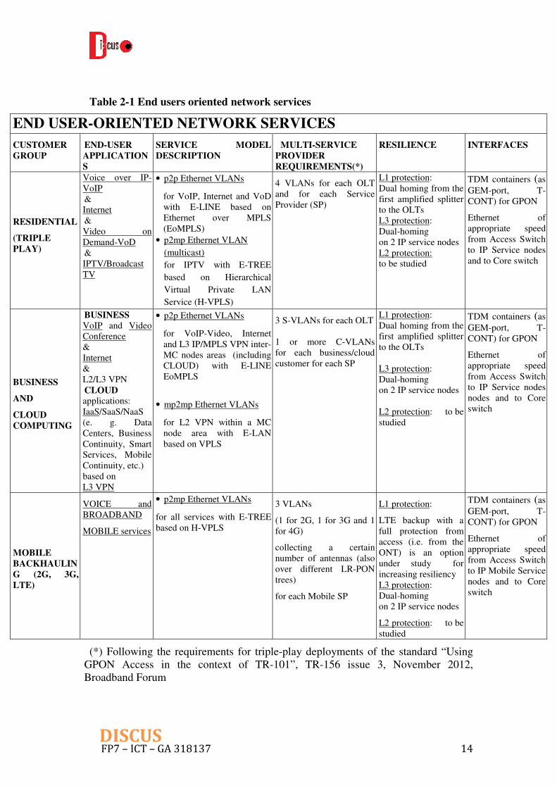
Table 2-1 End users oriented network services
END USER-ORIENTED NETWORK SERVICES
CUSTOMER
GROUP
END-USER
APPLICATION
S
SERVICE MODEL
DESCRIPTION
MULTI-SERVICE
PROVIDER
REQUIREMENTS(*)
RESILIENCE INTERFACES
RESIDENTIAL
(TRIPLE
PLAY)
Voice over IP-VoIP & Internet & Video on Demand-VoD & IPTV/Broadcast TV
• p2p Ethernet VLANs
for VoIP, Internet and VoD with E-LINE based on Ethernet over MPLS (EoMPLS)
• p2mp Ethernet VLAN
(multicast)
for IPTV with E-TREE
based on Hierarchical
Virtual Private LAN
Service (H-VPLS)
4 VLANs for each OLT and for each Service Provider (SP)
L1 protection: Dual homing from the first amplified splitter to the OLTs L3 protection: Dual-homing on 2 IP service nodes L2 protection: to be studied
TDM containers (as GEM-port, T-CONT) for GPON
Ethernet of appropriate speed from Access Switch to IP Service nodes and to Core switch
BUSINESS
AND
CLOUD
COMPUTING
BUSINESS VoIP and Video Conference & Internet & L2/L3 VPN CLOUD applications: IaaS/SaaS/NaaS (e. g. Data Centers, Business Continuity, Smart Services, Mobile Continuity, etc.) based on L3 VPN
• p2p Ethernet VLANs
for VoIP-Video, Internet and L3 IP/MPLS VPN inter-MC nodes areas (including CLOUD) with E-LINE EoMPLS
• mp2mp Ethernet VLANs
for L2 VPN within a MC node area with E-LAN based on VPLS
3 S-VLANs for each OLT 1 or more C-VLANs for each business/cloud customer for each SP
L1 protection: Dual homing from the first amplified splitter to the OLTs L3 protection: Dual-homing on 2 IP service nodes L2 protection: to be studied
TDM containers (as GEM-port, T-CONT) for GPON
Ethernet of appropriate speed from Access Switch to IP Service nodes nodes and to Core switch
MOBILE
BACKHAULIN
G (2G, 3G,
LTE)
VOICE and BROADBAND
MOBILE services
• p2mp Ethernet VLANs
for all services with E-TREE based on H-VPLS
3 VLANs
(1 for 2G, 1 for 3G and 1 for 4G)
collecting a certain number of antennas (also over different LR-PON trees)
for each Mobile SP
L1 protection:
LTE backup with a full protection from access (i.e. from the ONT) is an option under study for increasing resiliency L3 protection: Dual-homing on 2 IP service nodes
L2 protection: to be studied
TDM containers (as GEM-port, T-CONT) for GPON
Ethernet of appropriate speed from Access Switch to IP Mobile Service nodes and to Core switch
(*) Following the requirements for triple-play deployments of the standard “Using GPON Access in the context of TR-101”, TR-156 issue 3, November 2012, Broadband Forum

FP7 – ICT – GA 318137 15DISCUS
2.1.1 Residential Services
From the end-user application perspective, the residential services are usually named IP Triple Play, i.e. VoIP (Voice over IP), Internet, VoD (Video on Demand) and IPTV (or Broadcast/Multicast TV) applications.
Since we deal with many thousands residential customers on each metro area, the Service Provider generally isolates and manages each customer with PPPoE (Point-to-Point Protocol over Ethernet) or IPoE (IP over Ethernet) sessions. According to this model, the Network Provider (NP) can aggregate the customers’ sessions at Ethernet VLANs level (typically one VLAN for each service, aggregating traffic from all customers). Other network VLANs-based models taking into account specific customer VLANs, i.e. at least 1 VLAN for each residential customer, could be the subject for future studies inside the DISCUS Project, provided that the VLANs scalability issue, that is present in common Ethernet metro switches networks (see Sub-Chapter 3.3), can be properly addressed over the LR-PONs.
The simplified model considers that the VoIP and Internet services are based on PPPoE sessions established between the CPE (Customer Premises Equipment) connected to the ONTs and the BRAS (Broadband Remote Access Server, one of the Service Provider edge IP/MPLS service equipment). The BRAS applies AAA (Authentication, Authorization and Accounting) and QoS policing on the PPPoE frames and sends the encapsulated IP packets to the SP IP/MPLS grooming/routing function, that in turn requires a transport service over the DISCUS Core network (see next Sub-Chapter 2.2, “Core-oriented network services”, in particular the IP/MPLS services nodes and peering points for the Photonic layer or the Packet Transport Core layers). The VoD service is a point-to-point service based on the IPoE protocol, delivered to customers from the SP VoD Server. Also the IPTV service is based on IPoE and is distributed to all users as a point-to-multipoint service from the SP IPTV Head-End.
Figure 2-3 shows the end user-oriented network service model over the LR-PONs and the MPLS/MPLS-TP access switch on MC node, that is in turn connected to the SP Service node (directly if the access switch is co-located with the SP node or through the MPLS/MPLS-TP core switch and the photonic layer if it is not co-located).
In the present simplified model, on the LR-PONs for each service all the frames are encapsulated on the ONT on a 802.1q single-tag Ethernet VLAN ID. In particular, for each SP and each OLT we have 3 VLAN IDs identifying as a whole, at Ethernet level, respectively the VoIP, Internet and VoD p2p services, while the p2mp IPTV service has a common VLAN ID for all the OLTs with respect to each SP.
On the MPLS/MPLS-TP access switch of the MC node, the p2p VoIP, Internet and VoD VLANs are encapsulated into EoMPLS services (E-LINE) and delivered to the BRAS and VoD Server. The p2mp IPTV service is encapsulated into a H-VPLS service (E-TREE) on the MPLS/MPLS-PT access switch and delivered to the IPTV Head-End. The IP Service nodes can be co-located or not with the nearest end-user Metro/Core node. If they are not co-located, an interconnection over the DISCUS Core network must be used (see Sub-Chapter 2.2, “Core-oriented network services”,

FP7 – ICT – GA 318137 16DISCUS
in particular the MPLS/MPLS-TP access switch to the Photonic or to the MPLS/MPLS-TP Core switch).
Among the required functionalities, the resiliency at Layer 1 (L1) level should be based on dual homing from the first amplified splitter to working and protection OLTs, located respectively in the working and protection MC nodes (see some preliminary studies in chapter 4). The Layer 3 (L3) protection would be based on dual homing on two IP service nodes (co-located respectively with the working and protection MC nodes), while L2 protection would be coordinated with L1 and L3 resilience functionalities, in order to achieve a restored packet connection.
Figure 2-3: Residential services through LR-PON and MPLS/MPLS-TP access
switch on Metro/Core node for a generic Service Provider
2.1.2 Business and Cloud Services
The business services are offered by SPs to Large Enterprise and/or Small Office/Home Office (SOHO) customers as well as Public Administrations and Institutions. The main services are VoIP and Video Conference, High Speed Internet (HSI), L2 VPN (Virtual Private Network) between corporate sites located within the MC node coverage area (i.e. Intranet/Extranet data transfer, also called “business or mission critical” traffic) and IP/MPLS VPN for corporate sites located in different MC node coverage areas (i.e. connected to different MC nodes). From the SP’s point of view, all these services are created at the customer premises by a switch/router named CE (Customer Edge) and are centrally managed by an IP service Edge node named PE (Provider Edge) (see Figure 2-4). The High Speed Internet service can also be treated separately at IP level by direct access to the Internet network through an Access Router (AR) (see Figure 2-4). The IP Service node can be co-located or not
FP7 – ICT – GA 318137 17DISCUS
with the nearest MC node. In case of L2 VPN, we generally assume that the SP edge is co-located, so that it can easily create, through the DISCUS MC node, the L2 any-to-any connections between the business customer sites. In case of IP/MPLS VPN, where it is implicit in the service that the PEs are located into different MC nodes sites, the IP/MPLS client traffic is transported over the core network between the SP IP/MPLS grooming/routing functions (see next paragraph 2.2, in particular the IP/MPLS service nodes client layer for the Packet Transport Core layer). A VPN remote access is available through national and international Internet access also with dial-up, Wi-Fi Hot Spot and GPRS/EDGE/UMTS/HSDPA connectivity.
The Cloud Computing services are a wide set of virtual IT services than can be classified as IaaS (Infrastructure as a Service), SaaS (Software as a Service) and NaaS (Networking as a Service). The most important ones are Data Storage, Virtual Dedicated Web Servers, Virtual Desktop, Business Continuity (also for Mobile) and Smart Services offered to Enterprise customers, Public Administrations and Institutions by the SPs Data Centres. They are based on IP/MPLS VPNs, as for business services.
Figure 2-4 shows the end user-oriented network service model over the LR-PONs and the MPLS/MPLS-TP access switch on Metro/Core node, that is in turn connected to SP Service nodes (directly or through the MPLS/MPLS-TP core switch and/or photonic layer).
The services on the LR-PONs are QinQ (double-tag) 802.1ad VLANs based. For example, one or more Customer-VLANs (C-VLANs) which represent the different services provided to the specific business/cloud customer are created at CE and managed on the LR-PON tree from the ONT to the OLT. For each SP, these C-VLANs are encapsulated into 3 Service-VLANs (S-VLANs), i.e. 1 S-VLAN (per OLT) representing VoIP/Video+HSI+IP/MPLS VPN, 1 S-VLAN (per OLT) representing direct High Speed Internet access and 1 S-VLAN (shared by all the OLTs to which the business customer sites are connected) representing L2 VPN within the MC node coverage area.
On the MPLS/MPLS-TP access switch of the MC node, the VoIP, HSI and IP/MPLS VPN are modelled as a p2p service encapsulated into EoMPLS (E-LINE) and delivered to the SP PE/AR. The PEs and ARs are in turn interconnected to the SP IP/MPLS grooming/routing function and then to the DISCUS Core Network (see next Sub-Chapter 2.2, “Core-oriented network services”, in particular the IP/MPLS services nodes and peering points for the Photonic layer or the Packet Transport Core layer).
The L2 VPN service within the MC node coverage area is emulated on the access segment as an mp2mp Ethernet (E-LAN) based VPLS service.
Among the required functionalities, resiliency at L1 level would be based on dual homing from the first amplified splitter to working and protection OLTs, located respectively in the working and protection MC nodes (see details in Chapter 4). Improved and full protection using two ONTs can also be applied to business customers that require higher resiliency levels, as described in DISCUS Deliverable 2.1 (Section 2.4). The L3 protection would be based on dual homing of the CE node on two IP Edge service nodes (co-located respectively with the working and protection MC nodes), while L2 protection would be coordinated with L1 and L3 resilience functionalities in order to achieve a restored packet connection.

FP7 – ICT – GA 318137 18DISCUS
Figure 2-4: Business services through LR-PON and MPLS/MPLS-TP access
switch on Metro/Core node for a generic Service Provider
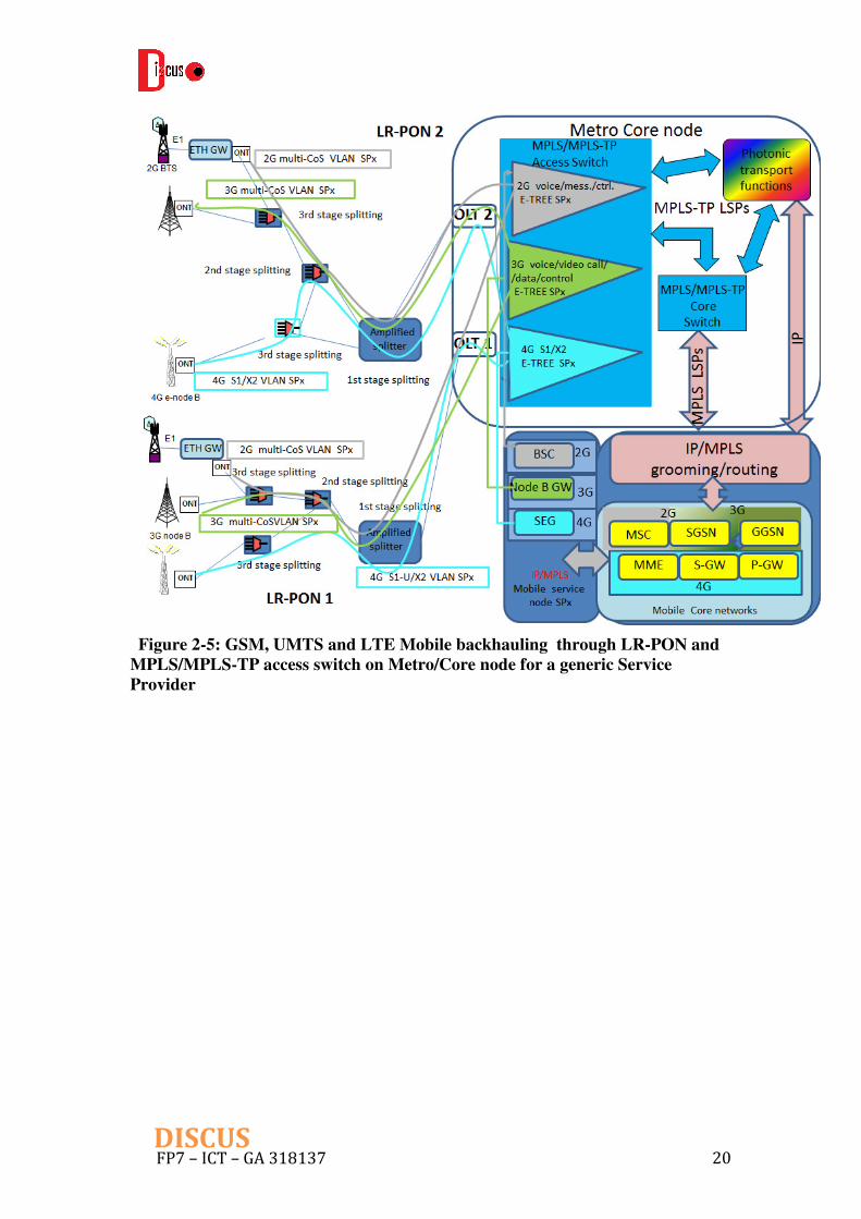
2.1.3 Mobile backhauling (2G, 3G, LTE)
The GSM (Global System for Mobile, i.e. 2G), UMTS (Universal Mobile Telecommunication System, i.e. 3G) and LTE (Long-Term Evolution 4G) backhauling services from Mobile Network Operators through the DISCUS access network involves Voice, SMS/MMS, Internet access, Video streaming and Data transfer for end-user services.
Figure 2-5 shows the end user-oriented network service model over the LR-PONs and the Packet Transport switch on MC node that is in turn connects to the SP Mobile Service node.
The 2G and 3G network services could be basically represented by p2p services encapsulated over Ethernet frames directly from the antennas (the 3G nodes B) or from a traffic gateway (for E1 circuits coming from 2G Base Transceiver Station BTS antennas) to the central controller (Base Station Controller BSC for 2G or Node B gateway for 3G), these last ones being in turn connected to the SP Mobile Core networks, that are the gates to the fixed networks. With respect to this simple p2p network service modelling, some initial scalability issues (due to the classical

FP7 – ICT – GA 318137 19DISCUS
Ethernet VLANs-based metro networks) led in most cases the network service to a p2mp (E-TREE) model from the central node to antennas groups, each one identified by a specific VLAN-ID (for example 1 multi-CoS VLAN for 2G services and 1 multi-CoS VLAN for 3 G services) and/or H-VPLS service in case of MPLS-based network backhauling. These VLANs/H-VPLS can cover more than one LR-PON tree.
The LTE services are IP broadband mobile services based on an Evolved access (E-UTRAN that includes the evolved radio base station named e-node B) and an Evolved Packet Core (EPC) mobile network. The bandwidth required from the e-node B to the EPC is presently of 400 Mbit/s and it will arrive to 1 G in the future. Therefore, for LTE backhauling a direct fibre access over LR-PON is needed. With respect to 2G and 3G, the 4G IP communication interfaces are established also between antennas, so that in principle an mp2mp service is needed in order to allow traffic handover and exchange between e-nodes B. In most cases this service model can be reduced to a p2mp (E-TREE) model with Hub & Spoke H-VPLS, since all traffic is often managed at central sites on a SEcurity Gateway (SEG) equipment in front of the EPC, generally co-located with the MC DISCUS node. As an example, S1 traffic (both user data and control) as well as inter e-nodes B communication X2 traffic (both user data and control) can be encapsulated into 1 multi-CoS VLAN, that is common to a certain number of e-nodes B, also covering different LR-PON trees. This S-VLAN identifies a specific Virtual Routing and Forwarding (VRF) into the SEG that acts as a PE.
The Mobile Service nodes can be co-located or not with the nearest end-user Metro/Core node. If they are not co-located, an interconnection over the DISCUS Core network must be used (see next Sub-Chapter 2.2, “Core-oriented network services”, in particular the MPLS/MPLS-TP access switch client layer to the Photonic or Packet Transport Core layers).
Among the required functionalities, for synchronization it is required to give support to the IP packet synchronization protocol known as IEEE1588v2. Regarding delay between antennas (BTSs, nodes B or e-nodes B), the requirement for data-plane in LTE (the most restrictive one) must be between 10 and 20 milliseconds, depending on the source. The Next Generation Mobile Networks (NGMN) Alliance, for example, specifies 10 milliseconds for the 2-way delay.
As regards resiliency, at L1 level LTE backup with a full protection from access (i.e. from the ONT) is an option under study for increasing resiliency. Improved and full protection using two ONTs can also be applied to backhauling locations that require higher resiliency levels, as described in DISCUS Deliverable 2.1. (see Sub-Chapter 2.4). The L3 protection should be based on dual homing over two SEG nodes, while L2 protection would be coordinated with the L1 and L3 resilience functionalities in order to achieve a restored packet connection.
In Figure 2-5 they are also shown the interconnections of the Mobile Core networks with the IP/MPLS grooming/routing functions that in turn are connected to the DISCUS Core Network (see next Sub-Chapter 2.2, “Core-oriented network services”, in particular the IP/MPLS service nodes and peering points for the Photonic layer or the Packet Transport Core layer).
FP7 – ICT – GA 318137 20DISCUS
Figure 2-5: GSM, UMTS and LTE Mobile backhauling through LR-PON and
MPLS/MPLS-TP access switch on Metro/Core node for a generic Service
Provider

FP7 – ICT – GA 318137 21DISCUS
2.2 Core-oriented network services
As explained in deliverable D2.1, the DISCUS core network mainly focuses on two layers: the photonic layer and the packet transport layer.
The photonic layer is envisioned to provide circuit connections for large size traffic demands, while the packet transport layer is devoted to transport services for small to medium size traffic demands.
This core network architecture looks reasonable to accommodate any kind of traffic that can be foreseen now and in the mid and long term period (about five and ten years from now respectively). However, at present, traffic estimations of DISCUS network are not yet available and therefore the core oriented network services must be defined based on other criteria than traffic size and patterns.
The criteria used to define core network services can be summarized as follows.
• Transport of Ethernet traffic will be the dominant demand in future core networks including the new 400G Ethernet whose standardization process has been just initiated by IEEE;
• Modulation formats and Super Channels structure will accommodate transparently any reach requirement of large European countries while preserving the option of using higher spectral efficiency, shorter reach formats wherever possible;
• Label Switched Paths (LSPs) of various capacities are the reference transport entities of the packet transport layer. Many LSPs are typically associated with a single, high capacity, optical interface for a better cost and energy efficiency, and enhanced operational flexibility.
• All resilience schemes available today are foreseen for the photonic layer assuming that all of them can be effectively exploited by IP service and peering nodes. On the contrary, just unprotected and restored services are provided to the packet transport layer assuming that this layer provides itself appropriate resilience tools for LSP services.
The network services towards core segment are also divided by two categories to cover both photonic layer and packet transport layer.
2.2.1 Photonic Layer Network Services
Photonic layer network services have been identified as shown in

FP7 – ICT – GA 318137 22DISCUS
Table 2-2, where they are associated to the classes of homogenous clients that share the same transport requirements.

FP7 – ICT – GA 318137 23DISCUS
Table 2-2 Photonic layer network services
PHOTONIC LAYER NETWORK SERVICES CLIENT
LAYER
NETWORK
SERVICE
DESCRIPTION
L0 RESILIENCE
INTERFACES
IP/MPLS
SERVICE
NODES AND
PEERING
POINTS
100 GE circuit connection
• Unprotected • Restored • 1:1 protected • 1+1 protected • Combined protection
and restoration
On client side: • 100 GE • Lambda client (*) On line side: • 32 Gbaud DP-16QAM single
carrier (dual 100 GE client) • 32 Gbaud DP-QPSK single carrier • 32 Gbaud DP-BPSK dual carrier
400 GE circuit connection
• Unprotected • Restored • 1:1 protected • 1+1 protected • Combined protection
and restoration
On client side: • 400 GE • Lambda client (*) On line side: • 32 Gbaud DP-16QAM dual carrier • 32 Gbaud DP-QPSK quad carrier
MPLS/MPLS-
TP
TRANSPORT
SWITCH
40 GE circuit connection
• Unprotected • Restored
On client side: • 40 GE • Lambda client (*) On line side: • 32 Gbaud DP-BPSK single carrier
100 GE circuit connection
• Unprotected • Restored
On client side: • 100 GE • Lambda client (*) On line side: • 32 Gbaud DP-16QAM single
carrier (dual 100 GE client) • 32 Gbaud DP-QPSK single carrier • 32 Gbaud DP-BPSK dual carrier
MPLS/MPLS-
TP ACCESS
SWITCH
40 GE circuit connection
• Unprotected • Restored • 1:1 protected • 1+1 protected
On client side: • 40 GE • Lambda client (*) On line side: • 32 Gbaud DP-BPSK single carrier
100 GE circuit connection
• Unprotected • Restored • 1:1 protected • 1+1 protected
On client side: • 100 GE • Lambda client (*) On line side: • 32 Gbaud DP-16QAM single
carrier (dual 100 GE client) • 32 Gbaud DP-QPSK single carrier • 32 Gbaud DP-BPSK dual carrier
ENTERPRISE
CUSTOMERS
(TRANSPAREN
T LAMBDA
BASED
SERVICES
ACROSS
ACCESS AND
CORE)
40 GE circuit connection
Unprotected on access side, on core side: • Unprotected • Restored
On client side 40 GE On line side TBD, depending on LR-PON constraints
100 GE circuit connection
Unprotected on access side, on core side: • Unprotected • Restored
On client side 100 GE On line side TBD, depending on LR-PON constraints
(*) Lambda clients are supposed to carry one of the signal format already foreseen in the column, e.g. 32 Gbaud DP-QPSK single carrier
FP7 – ICT – GA 318137 24DISCUS
The resilience schemes proposed in the table are initial suggestions to be investigated. The final selection of resilience schemes to be actually used is the subject of WP7 further studies.
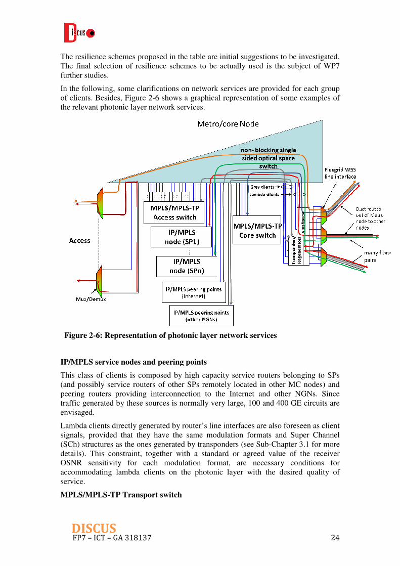
In the following, some clarifications on network services are provided for each group of clients. Besides, Figure 2-6 shows a graphical representation of some examples of the relevant photonic layer network services.
Figure 2-6: Representation of photonic layer network services
IP/MPLS service nodes and peering points
This class of clients is composed by high capacity service routers belonging to SPs (and possibly service routers of other SPs remotely located in other MC nodes) and peering routers providing interconnection to the Internet and other NGNs. Since traffic generated by these sources is normally very large, 100 and 400 GE circuits are envisaged.
Lambda clients directly generated by router’s line interfaces are also foreseen as client signals, provided that they have the same modulation formats and Super Channel (SCh) structures as the ones generated by transponders (see Sub-Chapter 3.1 for more details). This constraint, together with a standard or agreed value of the receiver OSNR sensitivity for each modulation format, are necessary conditions for accommodating lambda clients on the photonic layer with the desired quality of service.
MPLS/MPLS-TP Transport switch

FP7 – ICT – GA 318137 25DISCUS
The client is the MPLS/MPLS-TP transport switch that in turn provides LSP-based connections to the service routers. In this case 40 GE and 100 GE circuits seem adequate capacities since this layer is devoted to low to medium size traffic demands. This layer may be organized in a hierarchical way (as most data networks are today), with a number of central primary nodes connected to secondary peripheral nodes.
Also the MPLS/MPLS-TP transport switch may generate its own lambdas ready for long haul transmission and therefore the photonic layer will provide the corresponding lambda client service, with the same modulation format restrictions mentioned before.
The resilience schemes reserved for packet transport layer are limited to “unprotected” and “restored” because we assume that this layer provides its own resilience functions independently from the photonic layer.
MPLS/MPLS-TP access switch
The DISCUS MC node size may vary quite a lot in terms of the number of customers depending on the population density of the surrounding area. In low density areas the number of customers may be so small (e.g. 50 thousand or less) that it’s inappropriate to place in the MC nodes expensive and highly scalable service routers (up to 250 thousand customers are typical in today’s service routers technology). In these cases traffic aggregated by the access packet switch may be conveniently conveyed to a bigger parent MC node where service routers are located. Moreover, some SPs may prefer to deploy their service router in some selected MC nodes and therefore the core network must be able to transparently transfer their traffic to the selected locations.
The transport services foreseen in this case are the same as the ones provided to the MPLS/MPLS-TP transport switch, i.e. 40 and 100 GE circuits, and lambda clients. In this case 1:1 and 1+1 protection schemes are foreseen in addition to simple unprotected and restored schemes.
Enterprise customers
These clients may require high capacity dedicated circuits for high end applications that cannot be provided by the standard LR-PON protocol sharing the channel through TDM-TDMA. These demands are served by optical circuits that flow transparently trough LR-PON and core network segments. These optical circuits can connect enterprise users located at the same MC node or, going through the core network, users located in different MC nodes. Amplifiers and power leveling functions are needed, which are not shown in Figure 2-6. The capacity of such circuits will be 10, 40 and 100 Gbit/s and the interfaces will be Ethernet.
2.2.2 Packet Transport Layer Network Services
Packet transport layer network services are summarized in Table 2-3.

FP7 – ICT – GA 318137 26DISCUS
Table 2-3 Packet transport layer network services table
PACKET TRANSPORT LAYER NETWORK
SERVICES
CLIENT LAYER NETWORK
SERVICE
DESCRIPTI
ON
L2
RESILIENCE
INTERFACES
IP/MPLS SERVICE
NODES AND
PEERING POINTS
<10 G MPLS-TP LSP connection
• Unprotected • Restored • 1:1 protected • 1+1 protected • Combined
protection and restoration
On client side 40 GE and 100 GE On line side: • 40 GE (grey) • 100 GE (grey) • 32 Gbaud DP-BPSK
single carrier • 32 Gbaud DP-QPSK
single carrier • 32 Gbaud DP-16QAM
single carrier (dual 100 GE client)
10-40 G MPLS-TP LSP connection
• Unprotected • Restored • 1:1 protected • 1+1 protected • Combined
protection and restoration
On client side 40 GE and 100 GE On line side: • 100 GE (grey) • 32 Gbaud DP-QPSK
single carrier • 32 Gbaud DP-16QAM
single carrier (dual 100 GE client)
MPLS/MPLS-TP
ACCESS SWITCH
<10 G MPLS-TP LSP connection
• Unprotected • Restored • 1:1 protected • 1+1 protected
On client side 40 GE and 100 GE On line side: • 40 GE (grey) • 100 GE (grey) • 32 Gbaud DP-BPSK
single carrier • 32 Gbaud DP-QPSK
single carrier • 32 Gbaud DP-16QAM
single carrier (dual 100 GE client)
10-40 G MPLS-TP LSP connection
• Unprotected • Restored • 1:1 protected • 1+1 protected
On client side 40 GE and 100 GE On line side: • 100 GE (grey) • 32 Gbaud DP-QPSK
single carrier • 32 Gbaud DP-16QAM
single carrier (dual 100 GE client)
The MPLS/MPLS-TP transport switch provides packet based transport services on the core network. Its main task is stitching LSPs generated by client equipment (e.g. IP/MPLS routers) into MPLS-TP LSPs that are delivered to line interfaces (native IP traffic is managed as well whenever necessary). MPLS-TP LSPs are characterized by

FP7 – ICT – GA 318137 27DISCUS
effective and standardized Operation Administration and Maintenance (OAM) functions and for this reason they are the best packet transport solution for the core network. LSP stitching provides client equipment a single end to end LSP and it is preferred to hierarchical LSP because it avoids the label stacking typical of hierarchical LSP.
Some clarifications on network services are provided for each group of clients also for this core network layer.
IP service stratum and IP peering points
This class of clients is the one already considered for the photonic layer, but the services are packet rather than circuit based.
On the client side, MPLS LSPs of two kinds are accepted by the MPLS/MPLS-TP transport switch: up to 10Gbit/s and between 10 and 40 Gbit/s. This distinction, although arbitrary, may be useful for accommodating a number of these services on a single interfaces of appropriate capacity (either 40 or 100 GE), thus optimizing cost and number of optical ports.
On the network side, client LSPs are mapped into MPLS-TP LSPs and delivered to the appropriate line interface.
Resilience schemes are the same as the ones provided by the photonic layer while interfaces are limited to 40 and 100 GE since this capacity is considered sufficient for the packet transport layer.
MPLS/MPLS-TP access switch
Also in case of the MPLS/MPLS-TP access switch client, the services provided by the MPLS/MPLS-TP transport switch are LSPs up to 40 Gbit/s. Client MPLS LSPs are mapped onto line MPLS-TP LSPs. Client and line interfaces are the same as the previous client.
Figure 2-7 shows a graphical representation of typical interconnections of the MPLS/MPLS-TP transport switch with the photonic layer and various clients.

FP7 – ICT – GA 318137 28DISCUS
Figure 2-7: Representation of packet layer network services (realized by
MPLS/MPLS-TP core switch interconnections)
2.3 QoS preliminary requirements
A preliminary statement on QoS requirements for DISCUS network services can be derived from ITU-T Recommendation Y.1541. This Recommendation defines QoS classes and related parameters for IP network services, which could reflect the basic criteria on QoS considered in DISCUS MC node architecture design. QoS class definition is summarized in Table 2-4.
Table 2-4 IP network QoS class (class 0-7) definitions and network
performance objectives (ITU-T Y.1541)
Network performance
parameter
Nature of network
performance objective
QoS classes
0 1 2 3 4 5 6 7
IP packet Transfer Delay
(IPTD)
Upper bound on the mean IPTD
100ms 400ms 100ms 400ms 1s U 100ms 100ms
IP packet Delay
Variation (IPDV)
Upper bound on the 1 - 10-3
quantile of IPTD minus the
minimum IPTD
50ms 50ms U U U U 50ms
IP packet Loss Ratio
(IPLR)
Upper bound on the packet loss
probability 1x10⁻³ 1x10⁻³ 1x10⁻³ 1x10⁻³ 1x10⁻³ U 1x10⁻⁵
IP packet Error Ratio
(IPER) Upper bound 1x10⁻⁴ U 1x10⁻⁶

FP7 – ICT – GA 318137 29DISCUS
A proper mapping of these parameters into the MPLS/MPLS-TP network services will provide the DISCUS QoS requirements. These issues will be addressed by WP2.
Examples of end to end IP services which could be mapped into the former generic classes are shown in the following tables for IPTV and voice.
Table 2-5 Network performance parameters for IPTV services [2]
Parameter Threshold (≤)
Packet loss 1E-3
Packet jitter 5 ms
Program Clock Reference (PCR) jitter 5 ms
ÏGMP Latency 250 ms
Table 2-6 Network performance parameters for voice service [1]
Parameter Threshold (≤)
Packet delay time 15 ms
Packet loss 1E-5
Mouth to ear delay 300 ms
In the access segment, a proper traffic dimensioning within Ethernet services must be guaranteed to fulfill the IP requirements of an end to end service. As an example, the following table shows various Ethernet (L2) services offered to Other Licensed Operators providing Internet access to their subscribers with different qualities (typically pricing can be different depending on the offered quality). The provided values refer only to the section between the CPE and the point of connection to the aggregation network and they will typically be transmitted in an S-VLAN, using p-bits to distinguish between QoS.
Table 2-7 Examples of performance parameters for the Ethernet (L2) services
offered to the other licensed operators
Services to other licensed operators
Class A Class B Class C
Priority (p bit) 4 2 0
Frame loss ratio 2E-4 4E-3 8E-3
Delay 50 ms 70 ms Undefinedº
Jitter 10 ms Undefined Undefined
Regarding the various types of residential services, they are typically managed via the CIR/PIR traffic contract of VLANs, which for voice and IPTV services are typically guaranteed over the internet service with strict priority. For the different qualities of internet access offered, a weighted round robin mechanism will be utilized so that, in

FP7 – ICT – GA 318137 30DISCUS
case of congestion, the corresponding percentage of traffic is discarded for each priority.
Different User-VLAN/p-bit association mechanisms can be used for customer and service provisioning, as specified in [3].
In 3G/4G mobile networks, Policy and Charging Control (PCC) functions are specified by 3GPP (3rd Generation Partnership Project) [4] so that the application servers dynamically control the end to end QoS of each user equipment traffic flow, via the following functions:
- PCRF (Policy and Charging Rules Function) which provides policy control and flow based charging control decisions.
- PCEF (Policy and Charging Enforcement Function) which enforces QoS for individual IP flows on behalf of the PCRF. PCEF is in charge of executing in the network the policies for QoS management provided by the PCRF, and typically is located within P-GW nodes.
PCRF dynamically controls the traffic tunnels and the respective end to end QoS (via the PCEF implementation) depending on the subscriber contract and credit, subscriber identity and also considering the network status.
In conclusion, generic QoS classes with specific target values for IP services have been identified, which can be used to implement the DISCUS supported services. In order to achieve QoS targets in the DISCUS network, a proper dimensioning of the different link capacities and a proper management of customer and service provisioning is required. Specific network functions well defined in the standards are also available for dynamic QoS management, which is especially relevant in fixed-mobile converged networks. More specific QoS requirements for DISCUS network services will be further investigated when designing and modeling the DISCUS architecture in WP2. The identified sets of DISCUS network services (including both end user-oriented and core-oriented) will be considered in the next chapter to derive the functions required in the DISCUS MC node.

FP7 – ICT – GA 318137 31DISCUS
3 Overall DISCUS Metro/Core Node Design
This chapter includes a description of the overall DISCUS metro/core node design. Figure 3-1 shows an abstract view of functions as well as the associated interfaces to control plane that should be included in MC node architecture in order to well accommodate the DISCUS supported network services specified in Chapter 2. The mandatory functions in L1, L2 and L3 are described separately, which cover the optical switching, optical transport, optical line terminal (OLT) dealing with time and wavelength division multiplexing towards LR-PON, Layer2/3 MPLS/MPLS-TP based switching. A preliminary MC node dimensioning model is included in the end of this chapter.
Figure 3-1: An abstract view of DISCUS metro/core node as well as the required
interface for control plane
3.1 Layer 1: Optical Switching and Transport Functions
In this sub-chapter, we concentrate on L1 function of DISCUS MC node and present the considered technologies for optical space switching and optical transporting. A special focus is on how the considered L1 equipment could support the services listed in Chapter 2. It should be noticed that the L1 function at OLT dedicated to LR-PON is presented in Sub-Chapter 3.2.

FP7 – ICT – GA 318137 32DISCUS
3.1.1 Optical Space Switching Technology
In the DISCUS project, the Polatis’ piezo-electric all-optical switch has been considered to realize optical switching in the MC nodes, which are built from ultralow-loss beam steering elements providing a 3-D switching matrix requiring only 2N beam steering elements for an NxN switch (see Figure 3-2). This technology combines piezoelectric actuation with integrated position sensors to provide non-blocking connectivity between 2D arrays of collimated fibres directly in free space, thus avoiding the performance impairments associated with conventional MEMS micro-mirrors. Switching occurs completely independently of the power level, colour or direction of light on the path, enabling pre-provisioning of dark fibre and avoiding concatenation of switching delays across mesh or multi-stage switch networks. Because the switching technology is inherently traffic independent it provides a transparent optical layer to interconnect all the network functions on the same switch fabric and allows the node to evolve gracefully as signal formats and speeds change. More details of beam steering based optical switch can refer to APPENDIX I in the end of this deliverable.
Two switch configurations are provided for the DISCUS project: a dual-sided NxN switch and a single-sided NxCC (Customer Configurable) switch. Both these switch types are completely bi-directional and can be used interchangeably to build large non-blocking Metro/Core nodes using three-stage CLOS switching architectures.
Figure 3-2: Illustration of two-sided core piezo switching technology
The dual-sided (two-sided) NxN is a symmetric switch that has defined input and output ports where input ports can only be connected to output ports. In configuration any of the N input ports can connect to any of the N output ports in a strictly non-blocking manner. In the dual-sided configuration two piezo beam steering arrays are required, one for the inputs, and the other for the outputs as was shown in Figure 3-2. Even though ports are defined as “inputs” or “outputs” this is just nomenclature to define the port connectivity. The NxN switch is completely bi-directional and signals can be run either direction through the switch.

FP7 – ICT – GA 318137 33DISCUS
Very large scalable dual-sided switches can be built up of out of smaller asymmetric NxP and GxG switches using a Clos switching architecture as shown in Figure 3-3. This Clos switch architecture can be designed so that the overall node switch fabric can grow gracefully, while the node is in-service, without disturbing existing connections. If the entire node switch fabric is not needed on day-one then the node can be partially populated with only the number of switches needed to support the initial connections. As the node traffic grows, new switches can be added as needed allowing the overall node switch fabric can grow gracefully, while the node is in-service, without disturbing existing connections. Examples of double-sided optical switch with connection of OLTs and L2/3 switches are shown in Figure 3-4. It should be noted that compared with single-sided case, this type of optical switch is lack of flexibility due to the fact that distinguishing the ports at two sides of switch fabric is required. However, considered the current available technology on single swtich matrix, double-sides switch could support the size twice as large as the single sided (see Chapter 3 in D2.1). In case a large size of MC node is required, this type of switch is the only possible option. However, resiliency might become an issue, which is further discussed in Sub-Chapter 4.1.
Figure 3-3: Using double-sided switches to build large scalable double-sided
switch fabrics
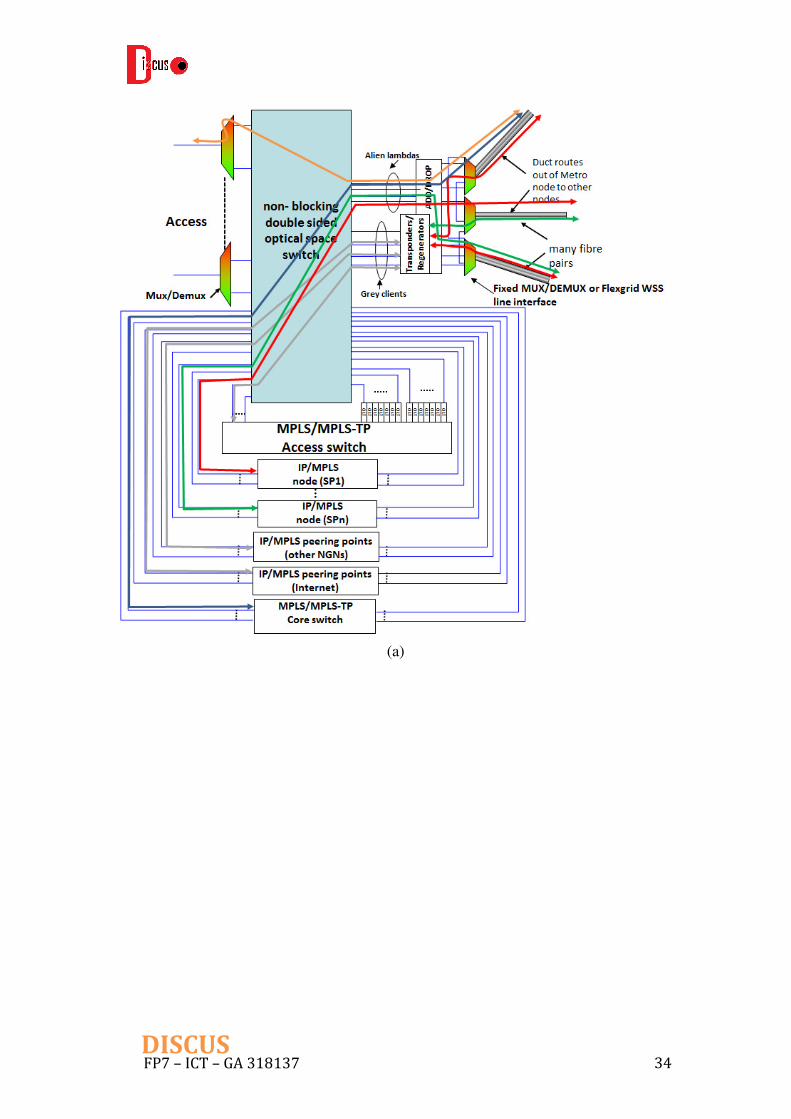
FP7 – ICT – GA 318137 34DISCUS
(a)
FP7 – ICT – GA 318137 35DISCUS
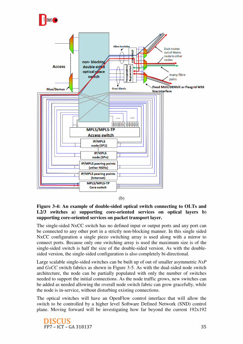
(b)
Figure 3-4: An example of double-sided optical switch connecting to OLTs and
L2/3 switches a) supporting core-oriented services on optical layers b)
supporting core-oriented services on packet transport layer. The single-sided NxCC switch has no defined input or output ports and any port can be connected to any other port in a strictly non-blocking manner. In this single sided NxCC configuration a single piezo switching array is used along with a mirror to connect ports. Because only one switching array is used the maximum size is of the single-sided switch is half the size of the double-sided version. As with the double-sided version, the single-sided configuration is also completely bi-directional.
Large scalable single-sided switches can be built up of out of smaller asymmetric NxP and GxCC switch fabrics as shown in Figure 3-5. As with the dual-sided node switch architecture, the node can be partially populated with only the number of switches needed to support the initial connections. As the node traffic grows, new switches can be added as needed allowing the overall node switch fabric can grow gracefully, while the node is in-service, without disturbing existing connections.
The optical switches will have an OpenFlow control interface that will allow the switch to be controlled by a higher level Software Defined Network (SND) control plane. Moving forward will be investigating how far beyond the current 192x192

FP7 – ICT – GA 318137 36DISCUS
matric size the technology can grow. Polatis also is in the process of further reducing the already low switch power consumption as part of the FP7 Programme, Colourless
and Coolerless Components for low Power Optical Networks (C3PO).
Figure 3-5: Using single and two-sided switches to build large scalable single-
sided switch fabrics
The Polatis will be providing both dual-sided 192x192 symmetric switches, and single-sided 192xCC switches.
3.1.2 Optical Transport Functions
MC node optical transport functional scheme is shown in Figure 3-6.
With respect to the general node architecture shown in Figure 3-1, Optical Performance Monitoring (OPM) functions have been added on the alien lambda client ports to provide quality check on these client signals. This block can be regarded as QoS demarcation point for alien lambdas. OPM functions are needed also in the WSS line interfaces as discussed below.
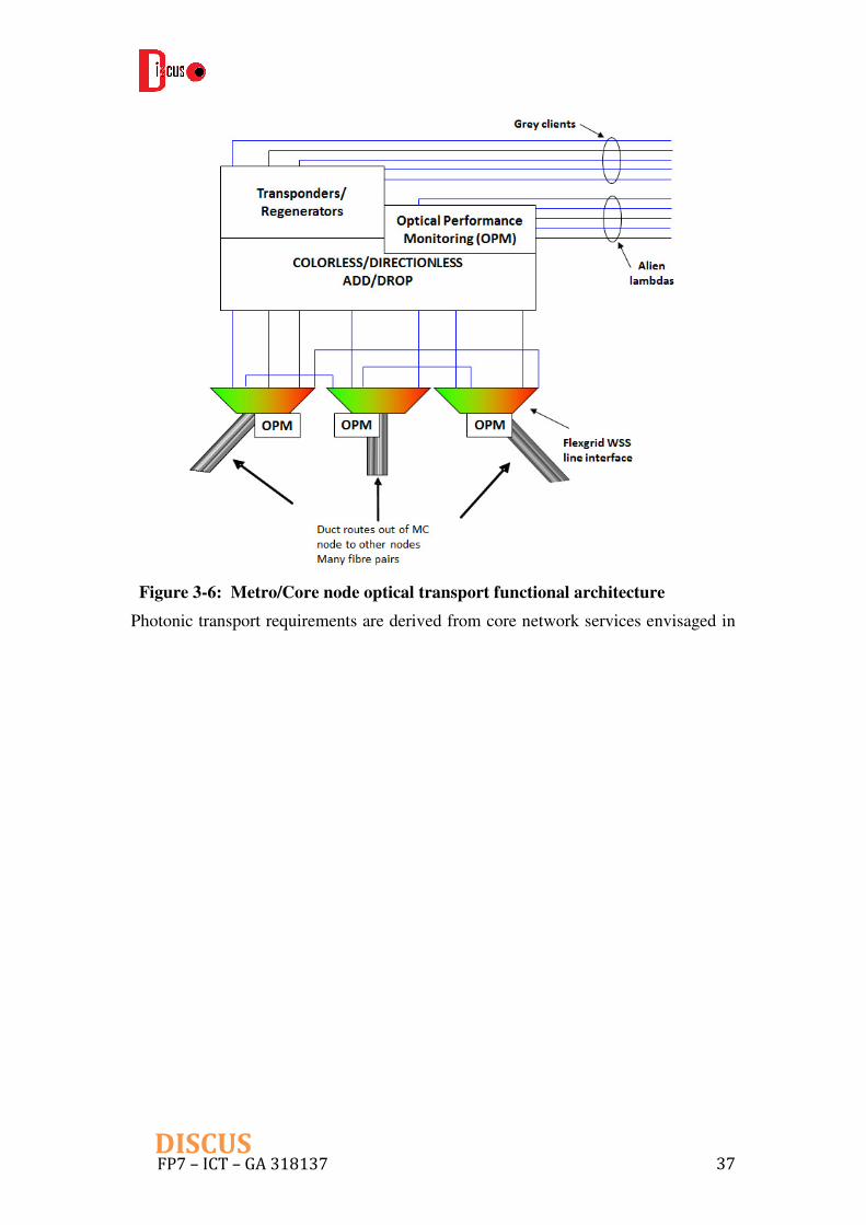
FP7 – ICT – GA 318137 37DISCUS
Figure 3-6: Metro/Core node optical transport functional architecture
Photonic transport requirements are derived from core network services envisaged in

FP7 – ICT – GA 318137 38DISCUS
Table 2-2 that consist in two kinds of single carrier OCh:
• 32 Gbaud DP-BPSK single carrier (40G)
• 32 Gbaud DP-QPSK single carrier (100G)
and three kinds of multi carrier SCh:
• 32 Gbaud DP-BPSK dual carrier (100G aggregate capacity)
• 32 Gbaud DP-16QAM dual carrier (400G aggregate capacity)
• 32 Gbaud DP-QPSK quadruple carrier (400G aggregate capacity)
The 32 Gbaud baud rate common to all services needs a clarification. This line baud rate is not the standard Optical channel Transport Unit 4 (OTU4) line rate recommended in ITU-T G.709, but it is rather a common figure of almost all second generation coherent systems. In today’s coherent 100G OCh, line rate is seldom the one standardized for OTU4 and every manufacturer propose a proprietary solution. The main difference among these solutions is the Forward Error Correction (FEC) code that is typically a proprietary technology of each manufacturer, but the general trend is a Soft Decision (SD) FEC code with about 20% overhead. This 20% FEC overhead, in addition to the 100 Gigabit Ethernet payload and the Optical channel Payload Unit (OPU) and ODU frame overheads leads to a 32 Gbaud baud arte that is easily supported by last generation Digital Signal Processing (DSP) technology as well as all transmitter and receiver optoelectronic components.
A second comment is needed on the 40G service. This service is based on a Dual Polarization-Binary Phase Shift Keying (DP-BPSK) modulation format in order to achieve a longer reach compared to DP-QPSK or DP-16QAM. Even with 20% FEC overhead, this service could be accommodated on a 24 or 25 Gbaud line signal that in turn may fit into a 25 GHz flexible grid optical slot. Hence this solution would exploit optical spectrum much better than the 32 Gbaud one that fits in a wider 37,5 GHz optical slot (spectral efficiencies are 1,6 and 1,07 bit/s/Hz respectively). However, 25 Gbaud has been discarded because it would introduce a second class of line interface hardware not compatible with all other services running at 32 Gbaud. The advantages of a single baud rate technology in terms of interface re-configurability and spare parts reduction are considered here predominant on spectral efficiency also looking at long term scenarios where the dominant core network service will be likely 100G or even 400G.
Requirements of functional blocks shown in Figure 3-6 are discussed below based on these two network service classes.
Transponders and regenerators
Optical transmission functional blocks used in DISCUS core network are transponders, regenerators and line interfaces, i.e., a line board that receives client signals directly from equipment backplane rather than from a client optical interface. The requirements shown here are common to all these elements that will be called for simplicity Line Interfaces (LI).
It seems worthwhile considering three categories of line interfaces:
1. Single-carrier LI providing 40G and 100G OCh
FP7 – ICT – GA 318137 39DISCUS
• single tunable laser source;
• modulation format can be configured either DP-BPSK or DP-QPSK;
• client can be configured either 40 GE or 100 GE;
• 2 configurations in total are possible:
o Single 40 GE: one carrier OCh using DP-BPSK;
o Single 100 GE: one carrier OCh using DP-QPSK;
2. Quadruple-carriers LI providing 100G and 400G SCh
• quadruple tunable laser source (carriers tunable in groups of two);
• modulation format can be configured either DP-BPSK or DP-QPSK or DP-16QAM for each carrier;
• clients can be configured either 100 GE or 400 GE or combination of them;
• 4 configurations in total are possible:
o Single 400 GE: one quadruple carrier SCh using DP-QPSK;
o Twin 400 GE: two dual carrier SCh using DP-16QAM;
o Twin 100 GE: two dual carrier SCh using DP-BPSK;
o 100 GE and 400 GE combined: two dual carrier SCh using DP-16QAM (400G) and DP-QPSK (100G).
3. Universal LI able to provide combinations of all OCh and SCh up to a
maximum 4 optical carriers per board
• quadruple tunable laser source (individually tunable carriers);
• modulation format can be configured either DP-BPSK or DP-QPSK or DP-16QAM for each carrier;
• clients can be configured among 40 GE, 100 GE, 400 GE or combinations of them;
• many configurations are possible: the ones listed before plus any combination of OCh and SCh up to a total of four carriers
Line interface configurability may be limited by the number of slot used by the board on the equipment backplane. More details on the LI optical requirements will be provided in Deliverable D7.2.
Further requirements common to all LI are:
• laser source wavelength stability must allow operation with 37,5 GHz carriers spacing for both OCh and SCh;
• spectral shaping must be performed at the transmitter so that linear crosstalk between neighboring carriers is negligible with 37,5 GHz spacing;
• standard 40 GE, 100 GE and future 400 GE client interfaces suitable for interconnection with co-sited client equipment will be provided for transponders;

FP7 – ICT – GA 318137 40DISCUS
• Standard electrical performance monitoring functions will be provided on Ethernet client interfaces for trouble shooting purposes.
It should be noted that we would remove legacy 10G transponders when the migration to the DISCUS architecture has been done. One of the major reasons is that 10G systems (based on Intensity Modulation Direct Detection) produce a strong impairment on coherent systems, which are the technology of choice for DISCUS core network. Anyway, 10G services are still foreseen in DISCUS architecture, but more probably they are only provided by the packet transport layer.
Alien lambdas and optical performance monitoring
Optical performance monitoring are fundamental functions in photonic networks since they provide crucial information on OCh and SCh status in all network links and nodes. This information is used in provisioning and troubleshooting activities and after any network reconfiguration to automatically recover the right OCh power level.
The essential information provided by OPM is the actual power of each OCh in a given measuring point. In case of SCh this concept should be extended to each individual SCh carrier. OSNR measurement capability is useful but it’s not strictly required.
Mandatory measurement points are:
• optical monitoring ports of optical preamplifiers and boosters on the WSS line interfaces;
• the add-drop blocks inputs.
Other measurement points may be envisaged to help intra-node fault management and misconnection identification (precise measuring points depend on the specific add-drop architecture).
At least two OPM technologies can be used:
• embedded Optical Spectrum Analyzers (OSAs);
• pilot tones modulation.
Both of them are effective and they are actually used in today’s equipment working on a 50 GHz fixed grid. However, tighter requirements may arise in a flexible grid environment with narrower channel spacing, e.g. higher OSA resolution may be required for a proper channel identification and power measurement.
WSS line interface
WSS line interfaces encompass all Reconfigurable Optical Add-Drop Multiplexer (ROADM) line functions: WSSs, splitters and optical amplifiers. They manage OChs and SChs on the lines and all pass-through optical traffic. Broadcast-and-select or route-and-select architectures may be used as in today’s fixed grid ROADMs.
Considering a flexible grid photonic network compliant with ITU-T G.694.1, a set of optical slots that will be managed by WSS line interface should be defined. The DISCUS core network will provide OCh and SCh based on single, dual or quadruple carriers all modulated at 32 Gbaud. This limits the kinds of optical slots to the following three:

FP7 – ICT – GA 318137 41DISCUS
1. 37.5 GHz slot for OCh;
2. 75 GHz slot for dual carriers SCh;
3. 150 GHz slot for quadruple carriers SCh.
WSS line interfaces will also provide the same kind of optical performance monitoring foreseen for alien lambdas on OCh and SCh.
Alternatively, fixed grid with 37.5 GHz (which is the smallest slot for OCh) could be used or co-exist with flexgrid WSS, which is not specified in the figures.
Add-drop functions
Add-drop functions include wavelength selection, switching and splitting-combining functions that are used to add-drop OChs and SChs.
Looking at flexibility, the main characteristics of add-drop functions are:
• directionless;
• colorless;
• contentionless.
The first two characteristics are mandatory to prevent any constraint on photonic layer services restoration and therefore they are considered basic requirements of the DISCUS node. Their implementation is easier with coherent receivers able to select a single OCh even when multiple OChs are delivered to the receiver input (this feature is typical of line interfaces with embedded spectral shaping functions).
Contentionless characteristics, i.e. the ability of an add-drop block to manage two or more OChs belonging to the same wavelength slot simultaneously, provide the following additional benefits:
• they allow scaling the number of add-drop wavelength slots up to the maximum allowed by node (i.e. all wavelength slots of all line interfaces);
• they enable regeneration without wavelength variation.
These features are definitely desired, but they typically require more complex implementations with respect to pure directionless and colorless add-drop, including high port-count optical switches.
However, in DISCUS node architecture a high port-count optical switch is already present and it can be exploited to provide at least partially contentionless features when combined with two or more directionless and colorless add-drop blocks. An example of this architecture is shown in Figure 3-7.

FP7 – ICT – GA 318137 42DISCUS
Figure 3-7: Example of add-drop architecture with two independent add-drop
blocks
In Figure 3-7 a degree 3 node is equipped with two independent colorless and directionless add-drop blocks connected on the client side to the main optical space switch. The number of add-drop wavelength slots is two thirds the total number of line interfaces wavelength slots, and wavelength contention probability is strongly reduced, although not completely cancelled, with respect to a fully contentionless add-drop. In most backbone networks maximum node degree is 3 or 4 and therefore the partially contentionless solution of Figure 3-7, perhaps augmented to 3 add-drop blocks, is a good compromise between node complexity, cost and performance.
3.2 Layer 1/2: OLT
In addition to the Ethernet/IP functionalities, PON specific elements, i.e. OLT functions are needed at DISCUS MC node, which connect the LR-PON and optical flat core, in order to make the time and wavelength division multiplexing work over LR-PON segment. This sub-chapter will concentrate on the design of OLT for both Layer 1 and 2.
3.2.1 The architecture of the metro/access network and of the Access Node
This introductory part is included to capture the access network architecture (see Figure 3-8) in a generic picture, independent from the DISCUS architecture, to
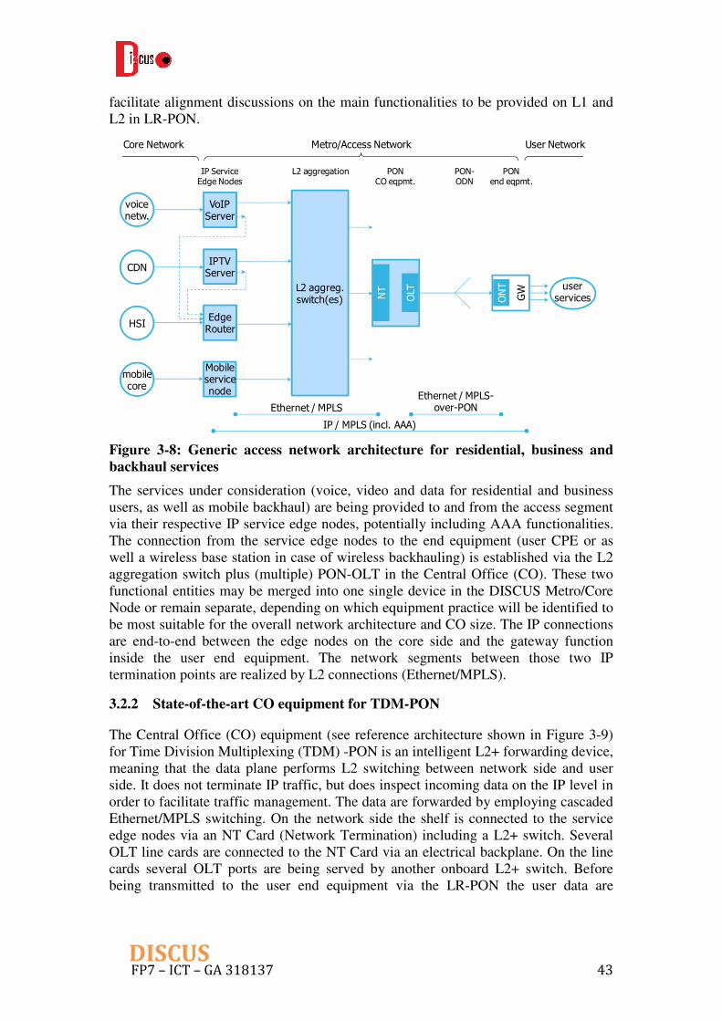
FP7 – ICT – GA 318137 43DISCUS
facilitate alignment discussions on the main functionalities to be provided on L1 and L2 in LR-PON.
IP / MPLS (incl. AAA)
Ethernet / MPLSEthernet / MPLS-
over-PON
PONCO eqpmt.
PONend eqpmt.
PON-ODN
L2 aggregationIP ServiceEdge Nodes
Metro/Access Network User NetworkCore Network
L2 aggreg.switch(es)
EdgeRouter
OLTNT
ONT
GW
IPTVServer
VoIPServer
HSI
CDN
voicenetw.
Mobileservicenode
mobilecore
userservices
Figure 3-8: Generic access network architecture for residential, business and
backhaul services
The services under consideration (voice, video and data for residential and business users, as well as mobile backhaul) are being provided to and from the access segment via their respective IP service edge nodes, potentially including AAA functionalities. The connection from the service edge nodes to the end equipment (user CPE or as well a wireless base station in case of wireless backhauling) is established via the L2 aggregation switch plus (multiple) PON-OLT in the Central Office (CO). These two functional entities may be merged into one single device in the DISCUS Metro/Core Node or remain separate, depending on which equipment practice will be identified to be most suitable for the overall network architecture and CO size. The IP connections are end-to-end between the edge nodes on the core side and the gateway function inside the user end equipment. The network segments between those two IP termination points are realized by L2 connections (Ethernet/MPLS).
3.2.2 State-of-the-art CO equipment for TDM-PON
The Central Office (CO) equipment (see reference architecture shown in Figure 3-9) for Time Division Multiplexing (TDM) -PON is an intelligent L2+ forwarding device, meaning that the data plane performs L2 switching between network side and user side. It does not terminate IP traffic, but does inspect incoming data on the IP level in order to facilitate traffic management. The data are forwarded by employing cascaded Ethernet/MPLS switching. On the network side the shelf is connected to the service edge nodes via an NT Card (Network Termination) including a L2+ switch. Several OLT line cards are connected to the NT Card via an electrical backplane. On the line cards several OLT ports are being served by another onboard L2+ switch. Before being transmitted to the user end equipment via the LR-PON the user data are

FP7 – ICT – GA 318137 44DISCUS
processed in the TC/MAC layer that also accounts for dynamic bandwidth assignment (DBA), ranging, management (OMCI) and more functions typical of TDM-PONs.
to ODN
to ODN
to ODN
to ODN
to ODN
OLT Card SFP+
SFP+
SFP+
SFP+
SFP+
PON-
TC/MAC
Layer
L2+
switch
traffic
manager
OBC and aux functns.
CO equipment for TDM-PON
NT Card
L2+
switch
traffic
manager
e l e c t r i c a l b a c k p l a n e
OLT Card SFP+
SFP+
SFP+
SFP+
SFP+
PON-
TC/MAC
Layer
L2+
switch
traffic
manager
OBC and aux functns.
to ODN
to ODN
to ODN
to ODN
to ODN
optical links to
Service Edge Node(s)
Figure 3-9: Reference architecture of an Access Node containing TDM-PON
OLT line cards
Today’s PON equipment in the CO is organized in shelves. A single shelf can contain up to 16 line cards, each card carrying up to 16 PON ports (Gigabit-capable PON GPON) and each PON port serving typically up to 64 users on a single Optical Distribution Network (ODN). So a single shelf can provide GPON services to a group of 16k users which is sufficient for most European COs. The NT cards, on the other hand, provide uplink capacities of 8x10 Gbps to the L2 aggregation switch that in today’s architecture is separate from the PON equipment.
If this is to be scaled to 10G-PON services (or to TWDM-PON) and to be integrated into a network architecture with consolidated COs serving >50 k users per CO, then multiple shelves will have to be used with a reduced number of ports on the linecards. Alternatively, a new equipment practice comprising the optical ports as well as the L2 aggregation switch (which is still separate today) will have to be developped. Such approaches will be further elaborated in the course of the DISCUS project.
3.2.3 OLT architecture for TWDM/DWDM-PON
Many different architectures have been elaborated for Wavelength Division Multiplexing (WDM) -PONs. They differ from each other in the way how the WDM sources are realized (remotely/self-seeded sources, tuneable lasers, fixed wavelength lasers, laser arrays) and in the design of the outside fiber plant (wavelength agnostic, wavelength routing). In DISCUS, we consider WDM based PONs as the major technology for LR-PON segment. Since the selection of a specific WDM-PON architecture has ramifications on the functionalities required in the OLT, we will first collect those basic assumptions that will have an impact on the OLT architecture and on the wavelength management. The considerations here apply as well to hybrid Time and Wavelength Division Multiplexing (TWDM) -PONs. Additional considerations, specific for TWDM-PONs alone, will be discussed at the end of this sub-chapter.
ODN architecture

FP7 – ICT – GA 318137 45DISCUS
The ODN is largely optically transparent, i.e. it does not include wavelength routing elements in the field. This is for preserving the flexibility to arbitrarily reallocate wavelength channels to different services or operators as well as to allow for the user to freely tune to any of the optical service offerings (Figure 3-10 a). The OLT includes a fixed wavelength (de)multiplexer for selecting and combining the upstream and downstream wavelengths of the channel pairs (CP). On the user side the selection of the desired channel is accomplished by respective filter elements within the ONT.
For high-speed point-to-point DWDM channels, as foreseen in the DISCUS architecture e.g. for high end business customers (data centers), some sort of wavelength routing in the ODN can be considered for improving the power budget of these channels (Figure 3-10 b). The routing is based on a waveband approach for each of the down- and upstream direction: one band for TWDM serving the residential, small business and wireless backhaul channels, another band for DWDM providing for the high speed channels (Figure 3-10 b). This preserves freedom to flexibly reallocate wavelength channels within each band respectively, but keeps the service groups (TWDM and high speed DWDM) spectrally disjoint.
power splitters
OLT ports
DWDM or TWDM
ONU
ONU
ONU
ONU
ONU
ONU
broadcast end-to-end
WM
(a)
partly routingfeeder section
band diplexer
ONU
ONU
residentialTWDM
businesshigh speedDWDM
TWDM -PON
DWDM -PON
ONU
ONU
ONU
ONU
ONU
ONU
power splitters
broadcastdistribution/drop
TWDM customerson high split sub-ODN
DWDM customerson low split sub-ODN
WM
(b)
Figure 3-10: (a) Fully transparent ODN for DWDM- or TWDM-PON alone; (b)
partly routing ODN for mixed operation of TWDM and high speed DWDM
services, on different wavebands .
OLT architecture elements
The downstream and upstream channels in a TWDM- or a DWDM-PON can be organized in different ways. Preferably they are grouped into bands, one band for all downstream channels and one for all upstream channels. In a mixed network,

FP7 – ICT – GA 318137 46DISCUS
containing both TWDM and DWDM systems, the respective channel pairs are assigned in separate bands. The band assignments for the DISCUS architecture will be detailed in WP2, WP4 and WP5.
The passive wavelength mux/demux (WM) in the OLT is to be seen as a functional element that can be realized in different technologies resulting in different architectures in the details:
- Thin Film Filter (TFF) technology: This approach requires band separation
filters followed by single channel filters. The downstream (DS) and upstream
(US) channels are provided on different filter ports, unless an additional
DS/US combiner filter is used.
- Arrayed Waveguide Grating (AWG) technology: The potential for high port
numbers along with the periodic nature of the filter function of AWG’s allows
for using a single device for upstream and downstream channels and
depending on the available number of ports even for DWDM and TWDM
channels. Also in this case the different wavelengths are provided on different
AWG ports.
Providing the downstream and upstream direction per channel pair on different filter ports is particularly beneficial for
- use with optical transceiver modules having dual fiber interfaces
- OLT board hybrid integration of transmit and receive elements
- employing laser arrays and photodiode arrays in the OLT.
Today the optical transceivers for access are mostly made with single fiber interfaces and additionally include an internal optical diplexer for separating the downstream from the upstream direction. The periodic nature of the AWG filter function can be leveraged to provide both downstream (DS) and upstream (US) direction of any CP on a single filter port, respectively, thus avoiding the need for recombining DS and US after filtering. The diplexer filter inside the transceiver modules is the same type and can be used for all CPs within the group of TWDM or DWDM channels, respectively (Figure 3-11).
Channel Pair CP#3
filter FSR
downstream bandupstream band
Tx
Rx
diplexer
WM
transceiver module
Figure 3-11: Wavelength plan with fixed frequency difference between upstream
and downstream channel for any given channel pair (left); OLT equipment:
AWG filter and optical transceiver module with single fiber interface (right)
From a cost perspective it can be beneficial to assign broader bands to the downstream and/or upstream direction than needed for a given channel number on e.g. a regular 50 GHz grid. The broader bandwidth allows for relaxed laser specifications in terms of manufacturing accuracy and stabilisation. This applies specifically to the upstream in TWDM systems. Whereas the OLT lasers can may still comply with the 50 GHz grid, the upstream lasers are allowed to operate over a larger

FP7 – ICT – GA 318137 47DISCUS
optical spectrum. This approach has been taken for the new NGPON2 specification in G.989.2 [5], supporting ultra-low cost technologies for ONU lasers [6]. This in turn requires a different design for the wavelength mux/demux in the OLT. The fixed one-to-one relationship between downstream and upstream channel frequency (wavelength) is no more valid in that case. Cyclic filter designs (cyclic-AWG) are one possible option to cope with this requirement [6].
Optical amplifiers will have to be integrated into the Metro/Core Nodes for loss compensation as indicated in deliverable D2.1. However, they are not considered being part of the OLT, but will be addressed in the discussions of the LR-PON architecture in WP4.
Wavelength channel assignment and tuning requirements
When discussing architectures for supporting flexible assignment of bandwidth ressources on the optical layer, it is useful to distinguish between two business scenarii:
- the optical layer (active system equipment and outside infrastructure) is
operated by one single network operator (NO), providing access to the
network for multiple Service Providers (SP) that are clients to the NO
- multiple SPs get direct access to the ODN, thus also acting as independent
NOs; the infrastructure is operated by a third party Infrastructure Provider (IP)
We further distinguish between the use cases for p2p DWDM-PON and p2mp TWDM-PON:
- The p2p channels of the DWDM-PON need to have full wavelength flexibility
in downstream and upstream direction in order to allow for flexible choice of
available spectrum inside the DWDM-PON bands. This becomes particularly
important when previously occupied channels inside the bands are being
released and get reassigned to a new client. This full spectral flexibility must
be accomplished by respective transmit and receive devices both on OLT and
on ONT side.
- For the p2mp channels of the TWDM-PON the flexibility requirement may be
different. Full flexibility on the OLT side is not of paramount importance,
particularly not in case of a single NO. However, the ONT must be able to
tune to different OLT channels, either for selecting a specific service or for
subscribing to another SP. In case of multiple NOs the OLT will also have to
be able to tune its down- and upstream channels.
So for establishing different wavelength channels on the ODN, either for DWDM-PON or for TWDM-PON, there are two different possible architectures for the OLT. If the optical layer is operated by one single NO, then the flexibility can be enabled in the electrical domain whereas the optics remain fixed (Figure 3-12 a). In a more general approach, to be recommended when multiple NOs get access to the ODN, the flexibility will be enabled entirely in the optical domain (Figure 3-12 a). There two schemes could well support bit-stream and wavelength open access. More discussions on open access models will be provided in Sub-Chapter 4.3.

FP7 – ICT – GA 318137 48DISCUS
SP 1
SP 2
SP 3
SP 4
ODN 1
ODN 2
L2 switches
Linecard
λ1d,u
λ2d,u
λ3d,u
λ4d,u
single NO/IP
equipment
multiple
SP equipment
λ1d,u
λ2d,u
λ3d,u
λ4d,u
Linecard
OLT‘sL2
switch
(a)
multiple SP/NO
equipment
single IP
equipment
ODN 1
ODN 2
L2
switches
tuneable
OLTs
SP 1
SP 2
SP 3
SP 4
f iber switch
λ1d,u
λ2d,u
λ3d,u
λ4d,u
λ1d,u
λ2d,u
λ3d,u
λ4d,u
(b)
Figure 3-12: Multi-wavelength operation in PON: wavelength flexibility enabled
(a) in the electrical domain and (b) in the optical domain
Pay-as-you-grow
As the OLT equipment is organized in line cards residing in a shelf, there are two options to populate the slots in the shelf and the OLT ports on the line cards in a TWDM system. Either each line card is made for carrying a (complete) set of wavelength channels and each card serves an entire ODN (Figure 3-13 a). Or each linecard carries only one single wavelength channel. The miration towards multi-wavelength operation per ODN is then accomplished by adding linecards with additional wavelengths (Figure 3-13 b). This latter option is preferred, when the take rate of PON customers grows only slowly.

FP7 – ICT – GA 318137 49DISCUS
λ1
λ2
λ3
λ4
ODN #4
linecard #4
λ1
λ2
λ3
λ4
ODN #3
#3
λ1
λ2
λ3
λ4
ODN #2
#2
λ1
λ2
λ3
λ4
ODN #1
#1
(a)
λ4
λ4
λ4
λ4
λ3
λ3
λ3
λ3
λ2
λ2
λ2
λ2
linecard #4
#3
#2
λ1
λ1
λ1
λ1
#1
ODN #4
ODN #3
ODN #2
ODN #1
(b)
Figure 3-13: Two different OLT architectures for TWDM-PON supporting a
pay-as-you-grow deployment strategy
Operation of a multiwavelength PON: wavelength tuning and TDM-PON
synchronisation
Aside from management aspects (wavelength assignment and control), the requirement for a non-wavelength-routing ODN has some ramifications on the operation of the multiwavelength PON, specifically on the ONT transceiver module and on the OLT architecure. It must be ensured that the optical emission on one channel does not interfere with the emission on any other of the WDM channels (linear crosstalk). In downstream direction the WM filter ensures that only the correct wavelength can be injected into the ODN. In upstream direction there is no such filter in the ODN. So special care must be taken that the ONT transmitters emit light into the ODN only when
- they are tuned to the correct wavelength or
- the ONT transceiver module includes an optical transmit filter for the correct
channel or
- there is no traffic on the network other than control and management signals
Ensuring the correct wavelength setting of a laser before it is turned on requires either a very demanding optical set-up or a precise multi-parameter calibration during production. While this may be tolerable for the high speed channels in the DWDM-PON subsystem, this is generally not compliant with the ultra-low cost targets for the TWDM-PON subsystem. The same is true for the integrated transmit filter in the ONT module.

FP7 – ICT – GA 318137 50DISCUS
From a cost perspective the most promising approach is to set the ONT wavelength during a quiet window, e.g. a ranging window in the TWDM-PON, and continuously control the setting end-to-end during operation leveraging the WM-filter in the OLT. For this purpose the ranging windows must be synchonised across all wavelength channels on a given ODN such that the virtual upstream frame is identical for all of them on an absolute time scale. Therefore, the TC/MAC layers of the respective OLT ports must be coordinated in a suitable way.
3.3 Layer 2/3: MPLS/MPLS-TP switching
This sub-chapter describes the design for the electronic Layer 2/3 in the DISCUS Metro/Core node architecture that is required in order to support the network services models described in Chapter 2.
The L2/L3 functions are based on an Access switch and a Core switch, working at the border between the Layer 2 and the Layer 3 levels of the OSI protocol stack. The equipment duplication is due to the different functionalities that must be performed. The access switch will manage packet switching for a lot of LR-PONs access networks, with OLT cards directly integrated as interface cards into the switch itself, as described in D2.1. Furthermore, a first stage of aggregation function from the access switch to the core DISCUS network is also required. The core switch will enforce this grooming function on a second aggregation stage (with traffic coming also from the Service Providers backbone routers) and, on Metro/Core nodes, with a further switching process for packet re-aggregation over proper optical circuits, as described in D2.1 and in Sub-Chapter 2.2 of the present document. Therefore, as shown in Figure 3-14, we can summarize the main functionalities of the equipment in the following points (that will be a reference for the description of protocol implementations used in order to deliver the services):
1. VLANs encapsulation and local switching on the access switch and on the OLT of end-users traffic on each LR-PON;
2. local switching on the access switch between end-users connected to different LR-PONs;
3. add-drop on the access switch of local end-user traffic from/to the Service Provider node, in particular to its service edge;
4. aggregation and switching on the access switch of the end-user traffic to be delivered to a SP service edge not co-located with this access switch: traffic is sent to the core transmission paths, i.e. either to the photonic layer of the MC node (for high volume traffic) or to the core switch (for traffic consolidation in case the traffic levels do not justify direct wavelength connections across the optical core);
5. aggregation and switching on the core switch of traffic coming from the access switch that must be delivered to a remote SP service edge (described in point 4);
6. drop on the core switch of remote end-user traffic to the SP service edge, i.e. of the end-user traffic coming from an access network covered by another MC node, that has crossed the DISCUS network (described in points 4, 5);
7. switching and aggregation on the core switch of traffic coming from grooming and routing function of the SP node (i.e. from SP backbone routers);

FP7 – ICT – GA 318137 51DISCUS
8. switching at packet level on the core switch of the MC Hub nodes of traffic that must be re-aggregated into different optical paths across the DISCUS core network.
Figure 3-14: Main functionalities of DISCUS MC Access and Core switches
As preliminarily introduced in D2.1, these switches are Ethernet as well as MPLS (Multi- Protocol Label Switching) and MPLS-TP (MPLS-Transport Profile) based. They apply L2 Ethernet VLANs encapsulation and switching on DISCUS access LR-PON side, plus IP/MPLS switching between LR-PONs, IP/MPLS aggregation towards the SP node sides and MPLS-TP switching and aggregation on DISCUS core side. The MPLS/MPLS-TP switching/aggregation functions are implemented mainly in order to overcome the scalability limitations that a pure L2 VLAN-based Ethernet switching/aggregation determines (a limited range of 4096 VLAN IDs is available all over the network, even when QinQ Customer/Service-VLANs are used, since the network operator only manages the outer VLAN IDs). The MPLS framework has been standardized by IETF that, during last years, has also worked on a new implementation named “seamless MPLS” [7]. Meanwhile the MPLS-TP framework, also named “Packet Transport”, has seen a cooperation between ITU-T and IETF in order to approve at the end of 2012 the MPLS-TP standards [8][9][10][11][12][13].
A brief description of the MPLS and MPLS-TP implementations available today is given, in order to specify afterwards a reduced set of these functionalities that are required in the DISCUS MC node.
In both MPLS and MPLS-TP frameworks supporting client Ethernet traffic (e.g. the protocols encapsulation available for today’s metro networks), the service and transport entities are respectively named Pseudo-Wires (PWs) and Label Switched Paths (LSPs). As shown in Figure 3-15, the native L2 802.1q Ethernet VLANs-based client traffic is encapsulated at the User Network Interface (UNI) sides of the MPLS (or MPLS-TP) network into the PWs, that in the simplest case matches 1:1 with the
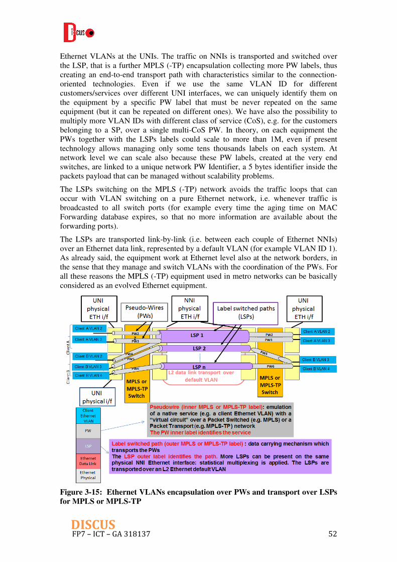
FP7 – ICT – GA 318137 52DISCUS
Ethernet VLANs at the UNIs. The traffic on NNIs is transported and switched over the LSP, that is a further MPLS (-TP) encapsulation collecting more PW labels, thus creating an end-to-end transport path with characteristics similar to the connection-oriented technologies. Even if we use the same VLAN ID for different customers/services over different UNI interfaces, we can uniquely identify them on the equipment by a specific PW label that must be never repeated on the same equipment (but it can be repeated on different ones). We have also the possibility to multiply more VLAN IDs with different class of service (CoS), e.g. for the customers belonging to a SP, over a single multi-CoS PW. In theory, on each equipment the PWs together with the LSPs labels could scale to more than 1M, even if present technology allows managing only some tens thousands labels on each system. At network level we can scale also because these PW labels, created at the very end switches, are linked to a unique network PW Identifier, a 5 bytes identifier inside the packets payload that can be managed without scalability problems.
The LSPs switching on the MPLS (-TP) network avoids the traffic loops that can occur with VLAN switching on a pure Ethernet network, i.e. whenever traffic is broadcasted to all switch ports (for example every time the aging time on MAC Forwarding database expires, so that no more information are available about the forwarding ports).
The LSPs are transported link-by-link (i.e. between each couple of Ethernet NNIs) over an Ethernet data link, represented by a default VLAN (for example VLAN ID 1). As already said, the equipment work at Ethernet level also at the network borders, in the sense that they manage and switch VLANs with the coordination of the PWs. For all these reasons the MPLS (-TP) equipment used in metro networks can be basically considered as an evolved Ethernet equipment.
Figure 3-15: Ethernet VLANs encapsulation over PWs and transport over LSPs
for MPLS or MPLS-TP

FP7 – ICT – GA 318137 53DISCUS
As described in the context of the ICT STRONGEST Project, the IP/MPLS framework is already adopted on the Service Providers backbone segments, where actually RSVP (Traffic Engineering) is used, with the support of label distribution protocols (like RSVP-TE) to create back-up LSPs for protection of high quality traffic (especially VoIP). The seamless MPLS solution can be considered the main evolution that involves also the service edge equipment (presently based on pure IP routing and forwarding) and the access segment (works are in progress in next generation GPONs standardization bodies, in particular the WT-178 of the Broadband Forum). It is based on the paradigm of supporting all service types (from residential to business and mobile) through a single IP/MPLS control and forwarding plane, that goes from the access to the service equipment through the IP/MPLS grooming/routing functions and peering points, in order to assure end-to-end MPLS capabilities along the network (see Figure 3-16). The OAM for end-to-end service performance monitoring can be applied only at PW level, due to the fact that the LSP is unidirectional and its label is removed at the last network hop (Penultimate Hop Popping-PHP). For this reason the main protection mechanisms are based on PW redundancy or on LSP protection via routing functions (i.e. with pre-calculated back-up LSPs supported by Loop-Free Alternates Fast Re-Route-LFA FRR), assuring in both cases recovery times that can be less than about 200 milliseconds.
Figure 3-16: End-to-end MPLS: Ethernet VLAN encapsulation over MPLS
PW and transport over MPLS LSP, with end-to-end OAM only on PW
The MPLS-TP (or Packet Transport) framework is a more “transport like” solution with respect to the MPLS solution (see Figure 3-17). It is used in some of today’s metro networks and it would have the appropriate requirements also for backbone networks. In fact, the control plane is separated from the data plane and a dedicated OAM channel is available in order to achieve the same characteristics of connection oriented transport networks in terms of monitoring and availability performances. These connection monitoring and fault location capabilities are obtained also because of bidirectional LSPs without PHP on LSP labels, that allow to have OAM not only at

FP7 – ICT – GA 318137 54DISCUS
PW level but also at LSP level. This last one triggers the Automatic Protection Switching (APS) from working to back-up paths, allowing 1+1 or 1:1 linear end-to-end trail protections or ring protections (similar to the ones available in the SDH networks), with recovery times below 50 milliseconds. In particular, the LSP 1+1 protection is a dual-fed and selective receiving mechanism applied with APS transported on the protection path. In case of fault the receive end selects the service according to the link state. On the other hand, the LSP 1:1 protection is a single-fed and single receiving mechanism applied with APS transported on the protection path. In case of fault the transmit end switches the service to the protection path and the receive end selects the service from the protection path.
Furthermore, the Packet Transport equipment is fully carrier class, not only in terms of redundant common parts, but also in terms of In Service Software Upgrade (ISSU), that allows traffic recovery within 10s milliseconds in case of software release upgrade.
Figure 3-17: End-to-end MPLS-TP: Ethernet VLAN encapsulation over
MPLS-TP PW and transport over MPLS-TP LSP, with end-to-end OAM on PW
and step-by-step OAM on LSP
In the context of the DISCUS MC node design, we have considered a MPLS and MPLS-TP multi-domain, naming the aggregation and switching functions as MPLS/MPLS-TP Access switch and MPLS/MPLS-TP Core switch. As a matter of fact, these equipment are hybrid equipment in the sense that they are mainly based on the MPLS-TP transport paradigm for core-oriented network services (especially for “circuit-like” OAM monitoring), but they do also implement the MPLS paradigm for end-user oriented network service creation and delivery to the SPs nodes. In more detail, the MPLS-TP framework is used for the connections between access and core switches and between MC nodes along the core network, while the MPLS framework is used for end-user network service support with MPLS PW creation on the access switch and MPLS LSP transport towards the SP nodes. These hybrid switches are

FP7 – ICT – GA 318137 55DISCUS
controlled by a separated SDN-based Control Plane (see Sub-Chapter 3.4), so that their main embedded functionalities are at data plane level for traffic encapsulation (over PWs) and forwarding (over LSPs), i.e. at the border between L2 and L3 of the OSI protocol stack. The L3 equipment functionalities could be limited to the Transmission Control Protocol (TCP)/IP protocols needed for node and service configuration purposes.
As regards MPLS on DISCUS MC node, both the access and core switches should be envisaged to have the forwarding MPLS functionalities. The access switch works at different MPLS levels (i.e. at PW and LSP level, for different types of interconnections as described in points 1-4 of the initial summary list), while the core switch is involved at MPLS LSP level only for delivery to remote SP service edge (point 6 of the initial summary list) or for the interconnection over the DISCUS Core network of the grooming and routing function of the SPs nodes, i.e. the SPs backbone routers (point 7 of the initial summary list).
The access switch together with the OLT (see Figure 3-18) works also at L2 Ethernet VLANs level, because its primary function is the end user-oriented network services creation via encapsulation on VLANs over each LR-PON tree (point 1 of the initial summary list). Then the equipment must associate these VLANs to the corresponding E-LINE, E-LAN and E-TREE services (described in Chapter 2), that in turn correspond to specific MPLS PWs used for switching between end-users connected to the same OLT (point 1 of the initial summary list) or to different OLTs (point 2 of the initial summary list). The PWs that must be connected to the SPs service edge (point 3 of the initial summary list) are encapsulated over MPLS LSPs. Here in the following we give some more information about these services.
• The E-LINE service, that is a point-to-point service used for most of
residential services (VoIP, Internet, VoD) and for business/cloud services
crossing the core network (as described in Chapter 2), is identified on the
access switch with a 1:1 mapping between the VLAN-IDs at the ingress/egress
OLT Ethernet interfaces and the PW IDs
• The E-LAN service, that is a multipoint-to-multipoint service used for VPN
business service on the area covered by a MC access switch (see Chapter 2),
can be represented by a Virtual Service Instance (VSI) that matches the
customer VLAN ID with PW IDs that identify the customer sites and that are
switched towards them all over the LR-PONs access network.
• The E-Tree service, that is a point-to-multipoint service used for residential
IPTV distribution and mobile backhauling (see Chapter 2), is based on an
Hub&Spoke H-VPLS solution, where a VSI instance on the access switch is
connected to an Hub PW towards the SP service node and to Spoke PWs to
the OLTs connected to the end users (i.e. the IPTV set-top boxes or mobile
antennas).
Note: For IPTV multicast distribution over the access segment, some Internet
Group Management Protocol (IGMP) functionalities are required in order to
save PON capacity. The OLTs are able to replicate the video stream only onto
the LR-PON trees where there is a user request through IGMP messages.
More specifically, the OLT receives IGMP join messages to multicast groups

FP7 – ICT – GA 318137 56DISCUS
from the end users and maintains the requested channels list acting as a Proxy
server, that means that for all its users it sends a single IGMP join message for
each multicast group to the access switch, that will implement IGMP
Snooping capabilities i.e. it sends towards the OLTs (only) the channels being
requested by the end-users.
Figure 3-18: End user oriented network service support on Access switch, with
Ethernet VLANs encapsulation over PWs, PWs switching and transport over
MPLS LSPs to SP edge service
If the SPs service edge nodes are not co-located with the access network, a packet transport over the core network is needed, that means traffic encapsulation into MPLS-TP frames (points 4-6 of the initial summary list).
As regards the MPLS-TP, both the access switch and the core switch should be envisaged to have the forwarding plane functionalities for Packet Transport over the DISCUS Core network. Since traffic has already been encapsulated on the access switch over MPLS LSPs, there is the need of an interworking function between the IP/MPLS and the MPLS-TP frameworks, that could be mediated by the SDN-based control plane, in order to switch the MPLS LSPs labels into MPLS-TP LSPs labels. The interworking subject has already been introduced in D2.1, as part of an IETF draft presently under development [14] that considers the problem of interworking between MPLS and MPLS-TP domains both at data and control plane levels. From this general point of view, the IETF draft defines an equipment named “border node”,

FP7 – ICT – GA 318137 57DISCUS
i.e. an hybrid equipment where the interworking between frameworks can be done at the same level of the OSI protocol stack, for example at LSP level. The access switch and the core switch of the MC node should be considered as border nodes, in the sense that they should perform the so-called “LSP stitching” (as represented in Figure 3-19), with a coordination done by the SDN-based control plane between the MPLS LSP label created in the IP/MPLS domain and the MPLS-TP LSP label created in the MPLS-TP domain, stitching together these different labels in order to create an end-to-end LSP across the different domains.
Figure 3-19: MPLS/MPLS-TP multi-domain network: transport over the
MPLS-TP core of an MPLS client layer. End-to-end multi-domain LSP created
with interworking between MPLS and MPLS-TP frameworks based on LSP
stitching on border nodes
On the access switch (see Figure 3-20), the client MPLS LSPs created for the end user-oriented network services are stitched onto line MPLS-TP LSPs, that can be directly transported over the photonic core layer (in case of large traffic demands) or that can be interconnected to the core switch (in case of small to medium size traffic demands).
In this last case the core switch (see Figure 3-20), that already receives packet transport-based frames, simply switches and grooms these MPLS-TP packets for proper exploitation of transport over the lambdas into the core network (point 5 of the initial summary list). Then, the remote core switch delivers traffic to the SP node after having done a reverse LSP stitching from MPLS-TP to MPLS (point 6 of the initial summary list).
Furthermore, on the core switch there is the need to directly create an MPLS-TP LSP in two cases. The first one (see Figure 3-20) is for switching and aggregation on the core switch of traffic coming from the SP node grooming and routing function (point 7 of the initial summary list), so that the SP MPLS LSPs need to be stitched, on the core switch, into MPLS-TP LSPs. The second case (see Figure 3-21) is for switching

FP7 – ICT – GA 318137 58DISCUS
at packet level, on the core switch of the MC Hub nodes, of traffic that must be aggregated into different optical paths across the DISCUS core network (point 8 of the initial summary list). As described in D2.1, since the flat optical core network needs the support of MC hub nodes where traffic is switched at Packet Transport level and then groomed over the photonic circuits, we can consider that the core switch should take in charge also the role of MPLS-TP LSPs creation, switching and grooming over lambdas into these Hub nodes.
Figure 3-20: Core-oriented network services implementation on Access and
Core switches with Packet Transport support and interworking between MPLS
and MPLS-TP. The MPLS LSPs delivery to SP edge service from the Core
switch is also represented

FP7 – ICT – GA 318137 59DISCUS
Figure 3-21: MPLS-TP Aggregation and switching on MPLS/MPLS-TP Core
switch of the MC Packet Hub node of core-oriented network services
3.4 Control plane
The control plane task (T6.3) in DISCUS aims at developing fast control mechanisms to enable dynamic operation of a number of access network functions. T6.3 will produce a control plane implementation that will be integrated during WP8 with the physical layer technology developed in WP5 and the optical switch developed in T6.2.
While the control plane implementation will target a specific set of service scenarios, in order to provide a broader view of control plane issues and architectures, we first present a brief description of the functionalities we believe a complete node control plane should be able to support.
Most of the work on the metro/core node control plane is carried out in task T6.3, which started in June (M8). In this deliverable, a broad view of control plane for DISCUS node is included as well as some scenarios and functions that will be implemented. Due to the early stage of this task, the description that follows should be considered a preliminary investigation and will be subject to modifications over the course of the task.
3.4.1 A broad view of the DISCUS control plane
While the use of control planes is rather common in core and metro networks, its use in the access, i.e. to dynamically provide new services to end users, is not widespread.

FP7 – ICT – GA 318137 60DISCUS
Access services tend to be managed manually from the network management interfaces.
As the DISCUS architecture aims to deliver highly dynamic and automated service provisioning and node operation, an access-side control plane is required. An ideal access control plane should allow dynamic on-demand provisioning of all services already introduced in service tables in Chapter 2, inclusive of protection mechanisms.
The DISCUS node architecture in Figure 3-1, shows all network equipment controlled by the node controller with either in-band or out-of-band connections. In order to provide dynamic services to the access and cooperation with the core network controller, the node controller interfaces with: Optical switch, OLTs, ONTs, remote amplifiers, access switch, service nodes, peering routers, transport switch, add/drop element, ancillary equipment (including OPM) and flexigrid WSS. It is envisaged that most of the interfaces will operate through a dedicated management network, while a subset, typically the interface to ONTs and remote optical amplifiers, will operate as in-band signaling through the data plane.
The node control plane maintains communication with the wider network control plane, which controls the core network and orchestrates the interaction among the multiple metro/core nodes. We are currently evaluating in Task 6.3 (“OpenFlow-based control plane design and implementation”) and Task 7.3 (“Core control plane”) whether all intelligent control functions should be operated by the network control plane, leaving the node controller to simply handle interfaces with the metro/core node devices, or whether the node controller will retain some decision-making capabilities.
High level requirements
This paragraph provides a high level requirements for the control plane architecture and functions. The DISCUS control plane is based on the Software Defined Networks (SDN) concept that encompasses a middleware layer (sometimes known as Network Operating System - NOS) providing the platform for applications by the abstraction of the transport layer and the virtualization of network resources and services. The NOS offers north-bound primitives (Application Programming Interfaces APIs) to hide the underlying networking details and enable applications and orchestration systems to program the network and request services from it.
In the DISCUS network scenario, the Network Provider, that owns the network infrastructure, grants the network resources to several Service Providers; these resources may be dedicated (such as nodes ports to which devices belonging to the SPs may be connected) or shared (such as switching capacity and link bandwidth). It’s therefore clear that, in such a scenario, the NOS should virtualize the underlying network, offering to the SPs a view in which it looks like it is the only network user, but keeping the resources assigned to the different SPs segregated from those of the others. The NOS should allow a SP to control only those resources for which it has the rights, according to some form of agreement with the NP. The network management and orchestration functions could themselves be seen by the NOS as applications running on top of it with administration (i.e. unlimited) privileges. In this sense, the NOS should provide a set of functionalities similar to those offered by a multi-user computer operating system.
As described in chapter 2, the DISCUS MC node will be able to deliver a set of network services that can be divided into two categories: (a) end user-oriented

FP7 – ICT – GA 318137 61DISCUS
network services and (b) core-oriented network services. The NOS should be able to virtualize both categories of network services and, in particular, both packet oriented (e.g. MPLS) and circuit oriented (e.g. optical) services.
A functional control plane architecture currently developed within IETF and under study within the ICT project IDEALIST is the ABNO (Application-based Network Operations) framework [15]. Figure 3-22 depicts the generic ABNO architecture whose details may be found in the IETF document. What can be highlighted here is that the document only describes a functional architecture and many different implementations are possible, thanks to the separation into functional components with clear interfaces between them. An implementation of this architecture may take several important decisions about the functional components:
• Multiple functional components may be grouped together into one software component such that all of the functions are bundled and only the external interfaces are exposed. • The functional components could be distributed across separate processes, processors or servers so that the interfaces are exposed as external protocols. For example, the OAM Handler could be presented on a dedicated server in the network that consumes all status reports from the network, aggregates them, correlates them and then dispatches notifications to other servers that need to understand what has happened. • There could be multiple instances of any or each of the components. For example, there may be multiple Traffic Engineering Databases with each holding the topology information of a separate network domain or layer. • Some of the components may not be instantiated because not needed.
Figure 3-22: Generic ABNO architecture

FP7 – ICT – GA 318137 62DISCUS
Such an architecture is flexible enough to accommodate the features discussed so far and other requirements that might be identified during the project lifetime.
3.4.2 Scenarios and functionalities implemented in the DISCUS OpenFlow
based control plane.
The OpenFlow implementation of the DISCUS node control plane, which will be developed in task T6.3, will target a number of service scenarios. Here we provide a potential list of scenarios and functionalities that might be targeted in the implementation. Each scenario reports a logical view of the potential testbed demonstrator as well as the main functional blocks of the ABNO architecture that might be involved in the operations. Notice that both diagrams only represent a logical view of the operations, and the real implementation might be organized using a different structure for the hardware and software components.
1. Provisioning of basic broadband connectivity to ONTs
This scenario emulates the provisioning of broadband service to a new PON user. It is assumed that the ONT from the user side has been connected, and the control plane carries out all necessary configurations in the data plane to activate the service. A simple diagram, showing the equipment involved is reported in Figure 3-23.
Figure 3-24 shows instead the required functionalities from a control plane perspective. The first action is executed by the ONT, which upon receiving a signal from the OLT, will start the standard registration procedure for activation. The OLT will forward the request to the OSS (Operation Supporting System)/NMS (Network Management System)/Application Server Coordinator. The OSS/NMS/Application Server Coordinator forwards the request to the ABNO controller, which checks the policy agent for the new user. After this the ABNO sends a request to the Path Computation Element (PCE) to create a route from the ONT to the service providers, which will require the assignments of VLAN/MPLS tags. Such values are updated in the database, while the PCE connects to the OLTs and electronic switch through the OpenFlow-based provisioning manager to update the respective data paths.

FP7 – ICT – GA 318137 63DISCUS
Figure 3-23: Testbed logical view for scenario 1: basic broadband proviiosning
Figure 3-24: Control plane interaction diagram for scenario 1.
2. Provisioning of a dedicated bandwidth service from ONT to metro/core node.
In this scenario (Figure 3-25) we implement the function where a user with or without multi-channel ONT capabilities requests a dedicated point-to-point link towards the metro/core node. Depending on the ONT capabilities and resource availability in the metro/core node, the capacity and delivery methods are negotiated between ONT and ABNO.
Following Figure 3-26, the requests starts when the ONT sends an in-band request to the OSS/NMS/Application Server Coordinator, which forwards the request to the ABNO server. The request will indicate capacity required and preferred delivery option (i.e. dedicated wavelength vs. shared channel). The ABNO controller verifies the user permissions with the Policy Agent, and then asks the PCE to find a suitable path with the specified characteristics. If no path is found, for example because there is no resource available that satisfies the requirements, the ABNO requests the PCE to find a suitable path with modified requirements (if these were indicated as options by the ONT request). This for example could be the case where an ONT requests a

FP7 – ICT – GA 318137 64DISCUS
2Gbps service over a dedicated wavelength, but that capacity is currently only available over a shared channel.
If the ONT acknowledges the PCE updates the Databases and requests the Provision Manager to operate the adequate configuration updates on optical switch, ONT, OLT and electronic switch.
Figure 3-25: Testbed logical view for scenario 2: provisioning of dedicated
bandwidth

FP7 – ICT – GA 318137 65DISCUS
Figure 3-26: Control plane interaction diagram for scenario 2.
3. Administrator managed or automatic cross-layer capacity increase or
balancing for traffic engineering purposes
This scenario (Figure 3-27) implements the response of the control plane to an increase in traffic over some of its interfaces. We will consider the situation where additional capacity might be required at the user side (i.e., if for example when, due to oversubscription, a given QoS cannot be ensured at the PONs with current capacity) and towards the core (i.e., if the levels of traffic aggregation towards a given destination are too high to satisfy QoS requirements).
Following Figure 3-28, in this scenario an alarm is triggered by the OAM Handler towards the ABNO, due to an increase of traffic in a given interface that could lead to a degradation of QoS. The ABNO check the Policy Agent for preferred response to the situation occurred. After this a request is sent to the PCE, which works with the Databases to find a suitable path satisfying the requirements given. Once a suitable path is found, the PCE updates the databases, and requests the Provisioning Manager to operate the adequate connections.
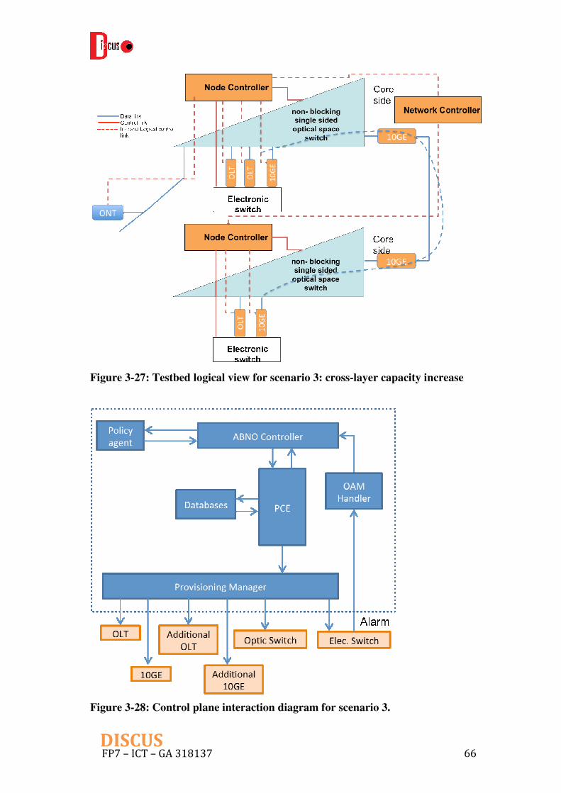
FP7 – ICT – GA 318137 66DISCUS
Figure 3-27: Testbed logical view for scenario 3: cross-layer capacity increase
Figure 3-28: Control plane interaction diagram for scenario 3.

FP7 – ICT – GA 318137 67DISCUS
4. Automatic activation of backup OLT in secondary metro/core node upon
failure detection and switching of traffic between primary and secondary
metro nodes.
This scenario (Figure 3-29) shows the dual-homed OLT protection strategy to protect failures at the feeder fiber or OLT. The aim is to restore the service as fast as possible. We initially will consider 1+1 protection, where the backup OLT is active and already connected to the backup feeder fiber. Then we will consider the possibility of 1:N backup OLT sharing, where the backup OLT is only connected to the feeder fiber after the failure occurs. Since two metro/core nodes are involved in the operation, communication is required between the control planes of the respective nodes.
Following the logical process for this scenario in Figure 3-30, the OAM handler receives an alarm (triggered from the optical switch or backup OLT), which is forwarded to the ABNO controller. In the 1+1 case the backup OLT can start re-activating the PON as soon as loss of light is detected. In the 1:N case, the ABNO will check the Policy Agent, and then get back to the PCE which will prompt the Provisioning Manager to activate optical switch and OLT. In the meantime the PCE will also find a route for the electronic switch. Notice that for protection purposes all routes should be pre-computed, so that the PCE will not require any computation time, but only use pre-stored values. After this all information is updated in the databases.
Figure 3-29: Testbed logical view for scenario 4: feeder fibre protection

FP7 – ICT – GA 318137 68DISCUS
Figure 3-30: Control plane interaction diagram for scenario 4
3.5 Preliminary Metro/Core node dimensioning model and Case
study
This sub-chapter presents a preliminary metro/core node dimensioning model as well as a case study. The mode is used to estimate the volumes of components and elements that make up the MC node structure for a range of node sizes and customer sustained bandwidth demands.
The customer base is assumed to consist of a number of segments of business customers and one combined segment for residential customers (this may be refined in later versions of the model. The business customer segments are; Very large business, Large business, Medium business, SME and Small business.
Data for the UK, from the UK government statistics offices and OFCOM reports, have been used to determine customer segment size and populations for the case study. The segmentation scheme used for the model as part of the input into traffic growth for dimensioning the MC node is shown in Table 3-1.
Although residential customer traffic will produce the highest busy hour load due to the high level of video content, the business customer base will require private VLAN and private circuit (PC) services. These private circuits increase the node size even if the business and residential busy periods are at different times of the day. It is assumed, for modeling and dimensioning purposes, that these private services will be carried as guaranteed bandwidth pipes within the LR-PON payload if the bandwidths are ~1 Gb/s or less and as separate wavelengths over the LR-PON fiber infrastructure if they are higher bandwidth >~1Gb/s.

FP7 – ICT – GA 318137 69DISCUS
The initial or day one legacy high bit rate VLAN and PC traffic may also be carried over legacy fibers and this option is a toggle in the model which can be turned on or off. If the toggle is set for legacy fiber then additional optical switch ports connect directly to the access fiber for these services and if the toggle is set for no legacy fiber then additional wavelength ports via the LR-PON AWGs are provided. The model and simplified MC node structure is shown in Figure 3-31.
Table 3-1: Business Customer segmentation and sizes based on UK data

FP7 – ICT – GA 318137 70DISCUS
UK
Da
ta:
Re
sid
en
tia
lS
ma
ll
25
,00
0,0
00
11 -
45 -
910 -
19
20 -
49
50 -
99
100 -
249
250 -
499
50
0 -
999
1,0
00
+T
OT
AL
To
tal
All
B
is
90.5
45
%8
.053
%9
.45
5%
2,2
23,5
10
UN
ITE
D K
ING
DO
M2,2
23
,51
01,7
74,6
90
388
,92
02
18,2
00
14
1,3
05
49,6
90
26
,10
57,5
75
2,7
10
1,3
40
2,6
10,5
35
4,8
34,0
45
GR
EA
T B
RIT
AIN
1,7
18,1
40
376
,24
52
11,0
85
13
7,0
50
48,2
05
25
,54
57,4
10
2,6
65
1,3
15
2,5
27,6
60
EN
GL
AN
D A
ND
WA
LE
S1,5
92,5
20
342
,72
01
91,7
35
12
5,0
05
44,2
25
23
,35
06,7
65
2,4
30
1,1
65
2,3
29,9
15
EN
GL
AN
D1,5
18,3
85
324
,83
01
82,0
10
11
8,7
40
42,1
60
22
,24
56,4
50
2,3
25
1,1
00
2,2
18,2
45
0.0
15
%
Bu
sin
es
s S
eg
me
nta
tio
n
Em
plo
ym
en
t siz
e
Very
La
rge
SM
Es
Med
ium
La
rge
4,0
50
8.6
26
%0
.692
%0
.122
%
2,3
81,8
10
190,9
95
33,6
80
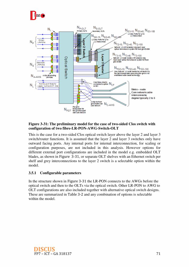
FP7 – ICT – GA 318137 71DISCUS
Figure 3-31: The preliminary model for the case of two-sided Clos switch with
configuration of two fibre-LR-PON-AWG-Switch-OLT
This is the case for a two-sided Clos optical switch layer above the layer 2 and layer 3 switch/router functions. It is assumed that the layer 2 and layer 3 switches only have outward facing ports. Any internal ports for internal interconnection, for scaling or configuration purposes, are not included in this analysis. However options for different external port configurations are included in the model e.g. embedded OLT blades, as shown in Figure 3-31, or separate OLT shelves with an Ethernet switch per shelf and grey interconnections to the layer 2 switch is a selectable option within the model.
3.5.1 Configurable parameters
In the structure shown in Figure 3-31 the LR-PON connects to the AWGs before the optical switch and then to the OLTs via the optical switch. Other LR-PON to AWG to OLT configurations are also included together with alternative optical switch designs. These are summarized in Table 3-2 and any combination of options is selectable within the model.

FP7 – ICT – GA 318137 72DISCUS
Table 3-2: Selectable optical switch configuration options within the
dimensioning model
In addition to the selectable option of embedded OLTs in the layer 2 switch or separate OLT shelves with grey optical ports to interconnect to the layer 2 switch, as mentioned above, other parameters which could be configured provided in the model are:
1. The sustained busy hour bandwidth per premises, this is a slider selectable from 100kb/s to 100Mb/s (note the peak rate for LR-PON service provision can be 10Gb/s if the ONU ports have 10Gb/s capability)
2. Private circuit traffic growth is linked to general sustained busy hour bandwidth growth but it is assumed that residential growth, which has a high entertainment video content, will grow faster that business VLAN and PC growth. A slider is provided that enables VLAN and PC growth to be driven as a proportion of the general traffic growth. This relationship is not known but is set to a value of 50% as an initial value for the model. VLAN and PC growth could be relatively small in the future when high bandwidth services can be offered over the public network, surveys in the UK suggest many business are considering transferring to broadband as superfast broadband is rolled out (ref N)
3. The number of MC nodes assumed for the population base being served determines the average size of the MC nodes and the range of node sizes in the network. The number of MC nodes is selectable in two ways within the model; a). it is directly set to a value via a slider and the corresponding average size metro-node is calculated, or b). the MC node size is set via a different slider and the number of MC nodes is calculated. The number of MC nodes can be set to any value in the range 4 to 1000 nodes and the size can be set between 10,000 and 2,000,000 premises as primary connections.
4. The LR-PON splitting ratio can be set, using a slider, from 32 to 2048. A typical value is used for the case study included in this document is 512.
5. An important parameter when dimensioning the metro-node node infrastructure is the amount of protection traffic the node will need to accommodate in the event of a worst case failure. The worst case failure is deemed to be a single adjacent metro node failure. The actual protection traffic level will depend on the relative sizes of the adjacent node and needs to be worked out for a particular national network layout that is optimized for minimum cost and energy consumption. However for this early model an average value of ~33% is used. This is another control variable in the model

FP7 – ICT – GA 318137 73DISCUS
and can be set to any value up to 100%. It should be noted that protection traffic could in principle exceed primary traffic if a very large node is adjacent to a very small node and the small node has to provide a proportion of the protection traffic of the large node. However this should be avoided as part of the end to end optimized network design.
6. The number of secondary OLTs needed depends on the protection traffic level, the protection mechanisms used and the configuration of the OLT relative to the optical switch. In the current version of the model the OLT is always after the optical switch which gives an option of 1:N shared protection mechanism for OLT protection. A toggle is therefore provided that selects between 1:1 protection and shared protection. If the shared protection option is set then the percentage of protection OLTs required is assumed to be equal to the percentage of worst case protection traffic required.
7. At day one the utilized bandwidth on the LR-PON including provision of private VLANS and PCs is, in a large number of situations, less than the capacity of a single up and downstream LR-PON wavelength, in which case an AWG multiplexer is not actually required. There is a toggle option included therefore to toggle day one LR-PON AWGS on or off. If toggled off and legacy fiber is used for initial high bit rate VLANs and PCs then no LR-PON AWGS are fitted initially and are only fitted as required as traffic grows. Fitting AWGS can be accomplished with minimal disruption to customer traffic by upgrading protection paths first and then protection switching the working paths to the protection paths allowing the protection paths to be upgraded. In this way interruption time can be limited to protection switching and restoration time.
3.5.2 Modeling and dimensioning variables
The dimensioning variables (shown in Figure 3-31) are listed in Table 3-3.
Table 3-3: Dimensioning variables calculated within the model
Variable Description
NP The number of primary LR-PONs terminating on MC node NS The number of secondary LR-PONs terminating on MC node NL The number of initial point to point fibers for legacy VLANs &
PCs NA-AWG The number of access AWGs terminating LR-PONs N The average number of wavelengths over the LR-PON
infrastructure NP-OLT The number of primary OLTs terminating the primary LR-PONs NS-OLT The number of secondary OLTs terminating secondary LR-
PONs NG2-10, NG2-40 and NG2-
100 Numbers of L2 grey ports at 10, 40 & 100Gb/s for L2 to L3
interconnect NG3-10, NG3-40 and NG3-
100 Numbers of L3 grey ports at 10, 40 & 100Gb/s for L2 to L3
interconnect NT2-10, NT2-40 and NT2-
100 Numbers of network L2 ports with tunable long reach optics for
fixed grid DWDM
FP7 – ICT – GA 318137 74DISCUS
NT3-10, NT3-40 and NT3-
100 Numbers of network L3 router blades with tunable long reach
optics for fixed grid DWDM NFG3-10, NFG3-40, NFG3-
100 Numbers of grey L3 router blades for connection to flex-grid
transponders (assuming flex-grid is not embedded router blade technology)
NC-AWG Number of Core facing AWGs for fixed grid DWDM NFGT Number of flex-grid transponders for flex-grid transport over the
core network. NCF This is the number of core fibres directly connected to the optical
switch
The following is a more detailed description of the variables and indication of calculation method:
• NP and NS are the number of primary and secondary LR-PONs required to service the customer base connected to the MC node. NP is calculated by dividing the number of customers connected by the effective LR-PON split. The effective LR-PON split is the physical split multiplied by a design fill factor which is a parameter for accommodating a level of future growth. NS is assumed to be equal to Np. This may need modifying when real physical layouts are consider for example when a smaller MC node is providing protection for a larger MC node it may have a greater number of secondary connections than primary, and for the larger node the reverse may occur. The average across all MC node will give NP = NS and for simplicity that is assumed for all MC nodes in the initial model.
• NL is the number of legacy fibres carrying private VLANs and Private circuits for the business community to the MC node. Bespoke networks that interconnect below the MC node are not considered in this model. Legacy fibre services would usually terminate on the local exchange site and therefore would not normally terminate on the MC node. If the DISCUS architecture was deployed there are two options for these legacy services. For services up to ~1Gb/s transport over the LR-PON system with the normal customer traffic could be used and would be the lowest cost and lowest energy option for connection between business customer and MC node. Circuits ~10Gb/s and greater could be served via additional wavelengths over the LR-PON infrastructure so no legacy fibre extension to the MC node would be required. The other option which can be used to support those customers that still insist on a direct fibre connection to the MC node to ensure physical separacy from the public network is to extend the legacy fibre over the backhaul network to the MC node using spare backhaul fibre. This is a form of bespoke network and because it can affect the size of the optical switch it needs to be considered within the model. The legacy fibre count is therefore also toggled in the model from all legacy services ~10Gb/ or greater connected over the LR-PON infrastructure via wavelengths (no additional point to point fibre to the MC node) to all legacy fibre systems of ~10Gb/s or greater terminated on the MC node. For both cases the lower bandwidth ~1Gb/s (or less) services are carried over the LR-PON systems.
• NA-AWG is the number of access DWDM fixed grid AWG devices required to terminate the LR-PONs when more than one wavelength is required. If the LR-PONs are terminated onto the AWGs before the switch then the secondary

FP7 – ICT – GA 318137 75DISCUS
LR-PONs will all need to be terminated onto AWGs. However if the LR-PONs are terminated onto the optical switch and then switched to AWGs then an N+1 shared protection system can be used saving ~66% of the secondary AWGs. However more switch ports will be required to accommodate the Lr-PON fibres and the AWG wavelength multiplexed fibre ports. At day one the LR-PONs may only require one wavelength, in this case the AWGs are not needed initially and can be added when traffic growth make additional wavelengths necessary. The option of not including AWGs for day one build is included as a toggle within the model.
• N is the number of wavelengths carried over the LR-PONs they will be a combination of LR-PON wavelengths required to service the bandwidth requirements of the majority of customers plus any additional dedicated wavelengths for high capacity (~10Gb/s) and greater customer services. In the model the number of LR-PON wavelengths scales automatically with the sustained bandwidth of the LR-PON customers and the private circuit and VLAN carried for business customers over The LR-PON traffic. In addition 10Gb/s and above circuits are allocated wavelengths over the LR-PON infrastructure.
• NP-OLT are the primary OLTs this is determined by the number of premises connected as primary connections to the MC node the LR-PON split assumed and the design average fill factor of the LR-PON, The design rules would ensure that some capacity for future growth would be provided and therefore the LR-PONs would not be installed with 1005 fill when initially installed.
• NS-OLT is the number of secondary OLTs required to handle the worst case fault condition that the MC node will need to support. By having the OLTs connected to the LR-PON systems via the optical switch enables the options of using 1:N protection of the secondary OLTs rather than 1:1 protection. Typically a metro-node will be providing protection for three adjacent metro-nodes and the average number (across all metro-nodes) of secondary OLTs would be one third the number of primary OLTs for a worst case failure considered of an adjacent MC node failure. If the OLTs where not connected via the optical switch then 1:1 protection would be necessary and NS-OLT would be equal to NP-OLT.
• NG2-10, NG2-40 and NG2-100 are the Grey ports from the Layer2 switch, for simplicity in the model they are assumed to connect to only the layer 3 router although in practice they could also connect to third party service provider equipment that is co-located in the MC node or Flex-grid transponders for transporting Ethernet services over the core network. It should be noted that the current node design does not consider these ports. However, we still keep them in the model for general case.
• NG3-10, NG3-40 and NG3-100 are the corresponding L3 router grey ports that correspond to the L2 grey ports for the L2 to L3 interconnect. In this early model they are equal to the layer 2 numbers but are kept as separate variables as the L2 count could be different if L2 services over the core network are supported. It should be noted that the current node design does not consider these ports. However, we still keep them in the model for general case.

FP7 – ICT – GA 318137 76DISCUS
• NT2-10, NT2-40 and NT2-100 are the number of network ports from the layer 2 switch. These are assumed to be tuneable long reach port cards suitable for transmission either over the core network or for direct connections to the access network either via direct fibre connections or wavelength channels over the LR-PON infrastructure or separate WDM systems supporting extension to the MC node would be required. For the current version of the model it is assumed that these are for private Ethernet VLAN connections > than 1GBE and is therefore the sum of the higher rate VLANs from 10Gb/s to 100Gb/s.
• NT3-10, NT3-40 and NT3-100 are the number of network ports from the layer 3 router at 10 Gb/s, 40 Gb/s and 100 Gb/s respectively. They are assumed to be equivalent to embedded transponder ports within the router blades. The have tuneable long reach optics and would usually go over fixed grid WDM systems over the core network although some can be for transmission over wavelengths over the LR-PON infrastructure. As bandwidth grows it is expected that these will migrate to the higher bit rate transmission systems and also to flex-grid systems but an graceful evolution path is required and allowing simultaneous use of allt technologies running side by side helps to enable that transition. One issue to be addressed is 100Gb/s and 10Gb/s over the same WDM systems. Ideally the 100Gb/s would be on non-dispersion managed links which might require these systems to be kept spatially separate by using separate fibres.
• NFG3-10, NFG3-40, NFG3-100 these are grey short reach optical ports provided on router blades for connection to Flex-grid transponders. There are a number of design options for flex-grid depending on how the market develops. The design shown in fig 1 assumes that Flex-grid transponders and optical multiplexers (e.g. Wavelength Selective Switches, WSSs) are a separate piece of equipment connected to the L2 and L3 switches and routers via the optical switch. They will take 10, 40 or 100 Gb/s tributaries and multiplex them onto fibre with an appropriate spectral allocation. Therefore grey ports are required between the various equipments in the MC node (in this example the Layer 3 router) and the flex-grid transponders. Another option would be to have the flex-grid transponders embedded into the routers and switches. This would save on grey ports but restricts the ability to mix different sources of traffic onto a common flex grid transmission link e.g. L2 and L3 services over the same system. This option will be included as a toggle within the model
• NC-AWG This is the number of AWGs for fixed grid wavelength connections over the core network. For the “optical island” concept, where the nodes reaches a set of MC node with a direct transparent wavelength connection, the minimum number of wavelengths = N -1 where N is the number of metro-nodes within the “optical island”. We assume that a MC node will have a minimum physical degree of at least 2 more typically degree three and possibly up to ~degree 5 so that the operating wavelengths will be distributed over these physical cable routes. The number of wavelengths and the distribution will be determined by the traffic matrix and the physical topology which is beyond the scope of this initial model. Therefore for the initial model a degree three is assumed and the number of AWGs is determined by the average traffic over inter MC node wavelength paths with a wavelength utilisation factor and a proportion of spare capacity for shared

FP7 – ICT – GA 318137 77DISCUS
protection/restoration systems. When flex-grid is also used the fixed grid capacity is reduced to match the flex-grid capacity provided.
• NFGT this is the number of flex grid transponders utilised over the core network Initially it is assumed that legacy fixed grid will dominate and the network will migrate to flex grid as bandwidth grow in the future. For the model this is implemented by assuming that links capacities requiring 40 Gb/s and 100Gb/s (and multiples thereof) will migrate to flex grid while 10Gb/s remains on fixed grid. when sufficient flex-grid has been deployed that the majority of links have a flex grid system it will be assumed the flex-grid will displace fixed grid, how that will be physically implemented requires more work.
• NCF this variable is to account for direct fibre connection from core cables to the optical switch This could be for private circuit and bespoke network use but more generally will be for through traffic where all the wavelengths carried over a fibre pass through the MC node and therefore do not need to pass through WDM equipment. Where necessary these fibres will be switched to optical amplifiers. Without a specific traffic matrix and physical topology it is difficult to estimate the number of pass through fibres required this will be estimated as part of the future work on core network design. For the model if the number of through wavelengths exceeds the number of wavelengths in a WDM system, taking into account a fill factor to allow spare capacity for growth, then it will be assumed that a whole fibre can pass through the node. In node configurations where the Core AWGs and flex-grid transponders etc. are all grouped as ancillary equipment then all core fibre would be directly connected to the optical switch flex-grid and fixed grid devices would then be switched to the appropriate core fibre as required.
3.5.3 Network structure
The structure and dimensioning of the MC node depends on the traffic matrix as well as the source and destination locations of content. The basic proposition of the DISCUS initial architecture is a FTTH (LR-PON) access network with symmetrical bandwidth capability, dual parented to a pair of MC nodes. The set of MC nodes are interconnected with a logical mesh of optical circuits traversing the core network. This structure enables the possibility of much more distributed network architecture with options for distributing content across the entire network and traffic load across the core.
There are three major network structures to consider:
1. A network similar to today’s where; content resides in a relatively small number of large data centers connected deep in the core network, and access to, and interconnect between, service providers is via a few large internet peering points. The characteristics of this architecture are to drive most traffic to and from access networks traversing the core network, increasing core bandwidth and creating some very high capacity routes.
2. A network that distributes the data centers to the MC nodes with popular content copied to all MC node sites while less popular content distributed across a smaller sub set of the MC node sites. For popular content the traffic associated with that content does not need to traverse the core network but can

FP7 – ICT – GA 318137 78DISCUS
be access and turned around within the MC node that the customer requiring the content is connected to.
3. The third network structure to consider distributes content and service provision to the edge of the access network. Customers connected to a particular MC node would access most content from access edge terminals. This would minimize the amount of traffic needing to traverse the core. Also if the peering points, for service and content provider access and interconnect, are also distributed across the MC nodes then the core traffic load would be minimized and also be more dispersed creating an affect similar to load balancing. This reduces the load on the core and reduces the number of high capacity links (100Gb/s and greater).
The three options all need to be incorporated into the model so the different strategies can be compared in terms of performance and cost. Option 3 is a particular strategy that DISCUS could enable and may produce the overall lowest cost and lowest energy consumption for the network and also enable a very high degree of scaling using distributed processes to remove bottlenecks in the network. It is recognized that this option is a radical change from the structure and operation of today’s network and needs careful examination to ensure viability and validation of the potential benefits. However as it may be a final outcome for the DISCUS architecture this options is the first options to be considered within the dimensioning and cost model. The other two options will be added for comparison later. Also to be added is sub-wavelength grooming and electronic add-drop multiplexing as at today’s relatively low traffic levels a full mesh of wavelengths interconnecting all the MC nodes may not be initially the most economic option. In any case we will need a transition model from the sub wavelength network, with electronic add drop multiplexers, that are still prevalent today with an evolution path to the flat optically interconnected core of the future DISCUS architecture.
One consequence of adopting the option 3 model is that the core bandwidths and capacity of the optical channels is smaller than projected from scaling of today’s network. This is of course one of the requirements for the DISCUS architecture if we are to avoid the economic and power consumption problems of scaling today’s networks.
3.5.4 Optical switch structure and dimensioning
The optical switch is the other major component in the MC node that needs dimensioning. The three structures for the optical switch layer mentioned in Table
3-2 are a large conventional two sided Clos switch structure, a single sided Clos switch structure and a partitioned switch structure.
The current version of the model has only the two-sided Clos switch fully implemented and all the results will be based on this switch configuration. The other switch structures will be included as selectable options in later versions of the model.
The other selectable options in Table 3-2 are also not fully implemented and will be completed in later versions of the model. All results that follow are for the options checked in Table 3-2 i.e. LR-PON fibers - AWGs - optical switch - OLTs as shown in Figure 3-32.

FP7 – ICT – GA 318137 79DISCUS
Figure 3-32: Configuration of LR-PON - AWG - optical switch - OLT
The maximum size of the strictly non-blocking switch structure is determined by the size of the center stage beam steering matrices. However a full sized switch is not required at day one and an edge fill strategy is used to grow the switch. However in the current version of the model the matrix size is selected from the smallest size needed for initial demand and then edge fill grown until a maximum size is reached. As growth then continues a larger center stage matrix is deployed and that new structure grown again using edge fill. This continues until the maximum user sustained bandwidth implemented in the model is reached (100Mb/s). The results for such a strategy are shown in Figure 3-33 and Figure 3-34. The former one illustrates the required optical switch size (using a three stage Clos configuration) and the latter one is for the optical beam steering matrix size as a function of sustained user bandwidth. Three different cases, i.e. 50,000, 300,000 and 1,000,000 customer premises, represent the smallest, mean and largest MC node coverage that may be required for the UK network.
Figure 3-33: Switch size required for MC node as a function of user sustained
bandwidth

FP7 – ICT – GA 318137 80DISCUS
Figure 3-34: Optical beam steering matrix size to build switch of required size
The model configuration parameters for these results as well as the following results presented in Sub-Chapter 3.5.5 are listed in Table 3-4
Table 3-4: The model configuration parameters for the case study.
Parameter Value
Total optical Access lines 27,839,260 LR-PON split 512 LR-PON split utilisation 70% LR-PON bandwidth Utilisation 80% LR-PON AWG no. Wavelengths 40 Core AWG No. Wavelengths 80 Number of MC nodes 100 Max Secondary traffic load as % of
primary traffic 54%
% traffic turned in node 70% % traffic turned in router 80% % Secondary OLTs 54% % through traffic of node core traffic 70% % Capacity for core traffic
restoration/protection 30%
Port bandwidth utilisation 50% Proportion of user bandwidth growth
driving VLAN and PC growth 50%
Embedded OLT blades in Layer 2 Switch False Max 10Gb/s OLTs per OLT shelf

FP7 – ICT – GA 318137 81DISCUS
The current beam steering technology largest matrix size is 192 x 192 optical ports and from Figure 3-34 it can be seen that for the model configuration used for the results shown a user bandwidth up to 50Mb/s can be provided on the average MC node size of 300,0000 premises served before switch capacity is exceeded. To go beyond this bandwidth requires larger switch matrices. This is possible with the Polatis beam steering technology but requires further development with matrix sizes up to possibly 500x500 with developments of the current technology. This matrix size would easily allow 1,000,000 premises to be served at 100Mb/s sustained rates with peak rates up to 10Gb/s.
The discontinuities in the curves in Figure 3-33 and Figure 3-34 are due to the synchronized nature of traffic growth where all customers increase bandwidth simultaneously. In practice statistical variations in demand would smooth these transitions and smoothing functions will be added later to give more realistic transitions. The other anomaly in the results, caused by the current model structure, is the reductions in switch size that can occasionally occur as bandwidth increases by a small amount. This is due to step changes in bandwidth across the customer base, in particular private circuit/private high speed VLAN growth can pass a threshold and bring in another business customer segment. This increases the number of 100Gb/s ports but reduces the number of lower capacity ports if this occurs at a marginal switch size the smaller total number of ports required can mean the next smaller size switch can be used. The problem arises because of the synchronized growth already mentioned, but also because the model does not store state and each new configuration, following a growth step, is calculated without any history of what had previously been installed. Again in practice switches would not be reduced in size (at least the matrix size would not be reduced as growth occurs) and an option to check previous state will be added in later versions so that such anomalies will not occur.
It should be noted that the optical switch structure block in Figure 3-31 could cause some confusion, it is meant to represent a two sided Clos switch, but the two sides of the rectangle in the figure is not meant to represent the two sides of the physical switch. The two sides in this figure are only used for illustrative purposes to show the equipment connected to the switch, it is not meant to represent a physical interconnect diagram. But it should be stressed that all the Clos switch structures can be equivalent as far optical path interconnect is concerned, a single sided switch just has greater flexibility as input and output ports do not need to be selected from two separate sets of ports, as in the case of a two sided switch structure.
The simplest way of thinking about a two sided switch is to first consider an input side to which transmitters (from equipment or network fibers) are connected and an output side to which receivers are connected and when the switch is configured optical paths are set up between the transmitters and receivers, which are the two separate sides of the switch. Then consider that any optical switched path between the two optical ports is bidirectional and therefore transmitter ports and receiver ports can be swapped over on any path, it is only the path that matters. Therefore any equipment can be connected to either side of the switch and even have ports split over both sides so that there is no imbalance between the loading of the two sides and the smallest size switch required for the total optical port count can be configured for optimal port utilization. A single sided switch is much simpler to configure as any two arbitrary ports can provide a path whereas the two side switch needs a port from both sides of the switch to form a path.

FP7 – ICT – GA 318137 82DISCUS
3.5.5 Initial results from dimensioning model
The following results are illustrative of the parameters that can be obtained from the dimensioning model. It should be stressed that the model is the basis of the MC node cost model and when the cost parameters with price learning curve are added we will have a model where options and control variables can be compared on a cost per customer basis i.e. configuration can be optimized against a single and common parameter. The other parameter that will be derived will be power consumption which will be part of the operational cost. To compare operational cost plus capital cost a discounted cash flow model will be implemented.
Important components for the cost of the MC node are the number of opto-electronic ports in the form of grey short reach ports providing interconnections within the metro-node and transponder or long reach optics ports with tunable wavelength transmitters for connection to network fibres and wavelengths traversing the core or access network fibers.
In Figure 3-35 the number of 10 Gb/s grey ports is shown. This is the sum of the dimensioning variables NGOLT and NG2-10.
Figure 3-35: The number of 10Gb/s grey ports as a function of user sustained
The first term is the number of grey ports from the OLT shelves to the layer 2 switch (note this option is included in the model via the embedded OLT toggle however Figure 3-31 only shows the embedded OLT option). If the embedded OLT option is selected then this term goes to zero. The second term is the Grey ports from the L2 switch to the L3 router as the number of these ports increases they are upgraded to 40Gb/s and then 100Gb/s so that the number of grey 10 Gb/s ports oscillates between

FP7 – ICT – GA 318137 83DISCUS
two small numbers. This is illustrated in Figure 3-36 which shows the embedded OLT option for all other parameters the same as for Figure 3-35. The x axis scale has been limited to 5Mb/s to increase the resolution so that the oscillations are clearly visible. It can be seen that the bounds on the number of 10Gb/s ports are now constrained for all MC node sizes to be between 1 and 4 ports. it may be that this range is too large, when 3 10Gb/s ports are required a 40Gb/s port may be fitted. This will be considered later when the cost ratio of 10 to 40Gb/s ports is included within the cost model.
Figure 3-36: Number of 10Gb/s grey ports for embedded OLT option
The number of 40Gb/s grey ports is shown in Figure 3-37 and the number of 100Gb/s grey ports in Figure 3-38. The 40Gb/s port count also oscillates because as 40Gb/s ports grow they are substituted for 100Gb/s ports. In the present version of the model the largest port capacity considered is 100Gb/s so as bandwidth growth occurs the 100Gb/s port count monotonically increases as there are not large capacity ports to substitute for then. It should be noted that the current results are calculated for each given value of user’s sustainable bandwidth. A smooth upgrade of the ports by the bandwidth increase might be done by taking the profile of peak points of the curve. For future work, we will also consider how to extend the preliminary model to efficiently support smooth upgrade in order to meet ever-increasing traffic demand from the user side.

FP7 – ICT – GA 318137 84DISCUS
Figure 3-37: The oscillatory growth of 40Gb/s grey ports for the case when
OLTs are not embedded into the layer 2 switches
Figure 3-38: Growth of 100Gb/s grey ports as a function of user sustained
bandwidth growth
It can be seen from Figure 3-38 that 100Gb/s ports begin to dominate quite early as user sustained bandwidth grows however a large proportion of the grey ports are OLT shelf to Layer 2 switch interconnect if the OLTs are embedded into the layer 2 switch

FP7 – ICT – GA 318137 85DISCUS
these grey ports can eliminated reducing cost and power consumption. Figure 3-39 shows the effect of embedding the OLTs into the layer 2 switch the effect is quite dramatic more than halving the number of ports required. This illustrates the importance or integrating functionality in the electronic layers as much as possible separation of functions and the interconnecting them into a system is not viable when bandwidths grow by orders of magnitude compared to today’s network and much more efficient switching and routing structures are going to be required.
Figure 3-39: Growth of 100Gb/s grey ports for the case when OLTs are
embedded into the layer 2 switch
3.5.6 Dimensioning Summary
This Sub-Chapter has described the beginnings of a model for dimensioning the metro/core nodes. The case study for the model is based on the UK with a 100 node network serving ~27 million premises. The main variables dimensioning the MC node size is the number of nodes serving the population and the customer sustained bandwidth.
The model is the basis for the cost and power consumption models, as a basic requirement of those models is the need to generate volumes of equipment and components that are required to implement a network solution. An important requirement of such models is internal consistency as parameters such as customer bandwidth and network size change.
The model will be further developed within WP2 “Architecture and modeling”. The other optical switch structures need to be added and a number of improvements will be made to the functionality. However, the present model as well as the case study results do provide indicative values for system component volumes for the two-sided Clos switch configuration and do illustrate the importance of efficient design of the

FP7 – ICT – GA 318137 86DISCUS
electronic layers. When a core transmission model and traffic matrices are available the MC node dimensioning model will be adapted for a network taking into account the variation in size of the MC nodes and the network interconnecting them.
FP7 – ICT – GA 318137 87DISCUS
4 Architectural Aspects
This chapter considers different architectural aspects with respect to resiliency, quality of service (QoS), open access, optical power budget, energy efficiency, and cost. Based on some preliminary analyses, the potential challenges and issues for the current DISCUS MC node design have been identified to be worked through during the rest period of the project.
4.1 Resiliency
As stated before, the main principle of the DISCUS MC node is to have a transparent optical layer in the form of optical space switch that fibre links towards both access and core segments, electronic layers (e.g. Layer 2/Layer 3 switches) could flexibly connect to. Therefore, the resiliency study starts from this optical space switch and will possibly extend to the overall node architecture during the rest period of the project. In this sub-chapter, we first consider the single swtich matrix, based on which reliability performance of Clos switch structure for large size of MC node is also analysed.
4.1.1 Reliability of 192x192 optical switch matrix
The expected reliability of the 192x192 optical switch matrix based on beam steering technology is calculated using the industry standard Reliability Block Diagram (RBD) Method. It is configured with dual Network Interface Cards (NICs) that support the customer Ethernet ports. The single switch matrix includes the Optical Switch Module (OSM), NIC, power supplies and other supporting circuitry. The detailed architecture can be found in APPENDIX I in the end of this deliverable.
To calculate the overall projected reliability, the detailed FIT (Failure in Time) rates and MTBFs (Mean Time Between Failures) are calculated for each of the major subcomponents and then combined using the RBD method to determine the overall switch chassis reliability. The Projected FIT rates and MTBFs are calculated by first determining the FIT rate based on the parts count method, using values form the BT
(British Telecom) handbook of Reliability Data, version 6/2002 and then weighing the data based on electronic field data from similar products. Using this method, the projected failure rate of the overall 192x192 optical switch matrix is 5,467 FITs and 20.9 years MTBF and for an individual connected optical path the projected FIT rate is 155 FITs and 735 years MTBF.
4.1.2 Reliability performance of Clos Switch
In this sub-chapter we are analyzing the reliability performance of a two sided three-stage Clos switch (See Figure 3-3) based on the input data received from Polatis switch module.
The maximum size of optical space switch for DISCUS metro/core node using series 6000 192×192 Polatis optical switch module is 18432x18432, which has 192 switch matrices in the first and third stage and 191 ones in the middle stage. The FIT of this switch can be calculated by summation of FIT of all the 192×192 switch modules.

FP7 – ICT – GA 318137 88DISCUS
This failure rate represents all the failures occurring in the metro/core switch even regardless of its impact on any connection or services. However, it implies the total reparation effort to fix faults.
p= 191, g=192, n=96, N=n×g=18432
FITtot = FITsw × (2g+2n-1)=5467 × (2×192+191)=3143525
where FITsw/FITtot denotes FIT of one switch module and N means the size of Clos Switch, i.e. the number input/output ports. As it is clear from the equation above, FITtot is dependent on the size of the switch (i.e. N). To see this effect, we tried to extract the lower bound of FIT rate in terms of switch size using following formula.
FITtot = FITsw × (2(g+n)-1) ≥ FITsw × (2 -1)
The following graph represents FITtot in function of N. The Blue curve shows the lower bound and red curve demonstrates the values for a configuration where n=96. As expected FITtot is increasing with the increase of the switch size. This value is too large for the maximum supported size considering 192×192 Polatis switch module. The lowest FIT for any configurations is reachable when the n is close to r (i.e. close to blue curve). When g>=96, the FIT shown in red curve is the lowest possible value and cannot be decreased further. The reason is that n has the maximum value of 96 and to increase the switch size r needs to be larger.
When FIT is larger than 3000000, it means approximately every 14 days there is a fault occurred, which is most probably not acceptable. Therefore there is a tradeoff between having the full flexibility in the node with large switch and the number of failures occurring in the node.
Figure 4-1: failure rate for different switch size.
On the other hand, it should be considered that not all the failures in the switch module will affect the optical paths. According to the design of the Polatis switch,

FP7 – ICT – GA 318137 89DISCUS
failures of individual optical path will not affect the other paths in the same switch module. Therefore, we’d also evaluate the connection availability for optical path.
For Clos structure shown in Figure 3-3, to have an optical path from an input port (A) to an output port of any switch in stage 3 (B) three switch modules are needed. In the worst case, when all other input/output ports are already occupied by other connection requests, there is only one option for optical path from A to B, which means the lower bound for the connection availability of this optical path. A reliability block diagram with series combination of three connected switch modules is shown in the following figure.
Figure 4-2: block diagram of an optical path from input to output port
FITpath = FIT 1+ FIT 2+ FIT 3 =155+155+155 = 465
Where FITpath denotes the FIT for the optical path in Clos switch and FITx represents the FIT for switch module in stage x in Clos structure (x=1, 2, or 3).
To calculate the availability of each optical path, we consider the calculated FIT for path above and three MTTR classes.The results are shown in the following table. As you can see in the worst case, with the full load of the switch availability is close to 5 nines (0.99999).
(MTBF>>MTTR) Av.=
Table 4-1: Availability of optical path
MTTR (hours) 4 8 24
Availability 0,99999814
0,99999628
0,99998884
Considering the dynamic nature of the traffic, especially in the access part, there could be time periods that not many optical paths are set up in the switch. The lower traffic demands in the switch, the higher number of available paths between each pair of input and output that can be used as the backup routes. In the extreme case, there is no other optical path is established, there could be up to m options for the new coming optical path (see Figure 4-3). In such a situation, the availability of this optical path is very high (i.e. very close to 1 if m>=2). Without knowing traffic matrix, it is impossible to have a more precise estimation of the FIT and availability of Clos switch. Anyway, we still can conclude that the availability for any optical path passing by Clos switch is in an acceptable level. A future study on resiliency will also consider the other parts (e.g. optical transport, L2/3 switches, etc.) of MC node.

FP7 – ICT – GA 318137 90DISCUS
Besides, failure impact would be interesting to be explored, in particular for a bid node, which are associated with a huge number of end users.
Figure 4-3: Different path options when the switch is not fully loaded.
4.2 Downstream Quality of Service
The major task, with respect to Quality of Service (QoS), is to resolve all downstream (DS) contentions between core network interfaces and user application terminals, while respecting QoS classes, bandwidth, delay, jitter & PLR (Packet Loss Ratio) contracts, as well as bandwidth fairness between flows with respect to these parameters.
This Section provides a preliminary comparison between DS QoS and US QoS (DBA) architectures, to identify any differences in treatment which are current, and currently proposed, DS QoS architectures may introduce. The main focus is on scheduling techniques for ensuring bandwidth fairness between user flows and between service provider (SP) flows.
Although the LR-PON OLT must have per-user knowledge to attach the correct XGEM Port-IDs to the XGEM frames, to reach the correct customer downstream, the question as to whether additional DS scheduling (contention resolution) of those individual user flows may be needed within the LR-PON OLT is left for future study. Certainly, if the following statement were true, then the major location of DS contention would be across the L2/L3 switch/router (within the metro/core node) into the LR-PON OLTs:
• LR-PON OLT interface line rate (BW_PON in Section 4.2.3.1) ≥ bandwidth scheduled into output port of L2/L3 switch (or OLT shelf switch if used in addition as in Section 4.2.3.1)
This would mean that all necessary scheduling could be performed either through the L2 access switch alone (QoS-aware, user-aware), or through the L2 switch (QoS-aware, user-unaware) and L3 SP routers (QoS-aware, user-aware). From the results of this Section, the former is expected to be fair to users, and the latter fair to SPs. However, there may be reasons, such as processing delays, for needing additional scheduling within the LR-PON OLT to ensure QoS.

FP7 – ICT – GA 318137 91DISCUS
4.2.1 Upstream QoS and Bandwidth Fairness
In the upstream (US) direction, QoS and bandwidth fairness are implemented by Dynamic Bandwidth Assignment (DBA). This is a scheduling procedure (Figure 4-4) whose task is simply to multiplex traffic from individual users’ Alloc-IDs (buffers) into the US TDMA stream of a single LR-PON, with strict priorities between QoS classes, while maintaining bandwidth agreements and fairness between different user flows within each QoS class. Techniques include: RR & WRR, pointers, and timers for peak rate limitation. See [16]. Alloc-IDs (buffers) transmit queue-length status reports upstream to the DBA scheduler, and the scheduler transmits resulting upstream bandwidth grants to Alloc-IDs within the BWmaps of DS XGTC frame headers [17].
Figure 4-4: Upstream QoS and DBA Scheduling into a LR-PON
Bandwidth fairness is ensured between individual users' Alloc-IDs and QoS classes by means of the DBA reference model in [17]. The important features for our purposes are as follows.
Maximum bandwidth is the upper limit on the total bandwidth that can be allocated to the Alloc-ID traffic flow under any traffic conditions, .
Bandwidth of all traffic cannot exceed the capacity of the upstream interface ( ),
, where is the Alloc-ID index. This basic stability condition implies no oversubscription of Assured Bandwidths.
Assigned bandwidth [bit/s] is assigned bandwidth for Alloc-ID .
The assigned bandwidth consists of two parts, guaranteed bandwidth, , and
additional bandwidth, . The guaranteed bandwidth consists of the Fixed bandwidth plus the Assured bandwidth. The additional bandwidth can be either Non-Assured bandwidth or Best Effort bandwidth.

FP7 – ICT – GA 318137 92DISCUS
Figure 4-5: Components of assigned bandwidth
Figure 4-5 [17] shows components of the assigned bandwidth. The fixed portion of the guaranteed bandwidth is statically assigned. The assured portion of the guaranteed bandwidth is dynamically assigned based on the offered load of the specific Alloc-ID. For the additional bandwidth assignment, the reference model supports both a rate-proportional criterion and a criterion based on provisioned priority and weights. The additional bandwidth is dynamically assigned based on the offered load of the specific Alloc-ID and the overall traffic conditions. The assigned bandwidth cannot exceed either the maximum bandwidth or the offered load. The OLT assigns bandwidth to each Alloc-ID in strict priority order:
Step 1: Fixed bandwidth is assigned, regardless of the offered load or traffic condition.
Step 2: Guaranteed bandwidth is filled by allocating the assured bandwidth to each Alloc-ID until it reaches to or satisfies the offered load.
Step 3: Non-assured bandwidth is allocated to eligible unsaturated Alloc-ID until it reaches the maximum bandwidth or satisfies the offered load, or the surplus bandwidth is exhausted.
Step 4: Best-effort bandwidth is allocated to eligible unsaturated Alloc-ID until it reaches the maximum bandwidth or satisfies the offered load, or the surplus bandwidth is exhausted.
Rate-proportional assignment of additional bandwidth
The important issue relates to bandwidth fairness between unsaturated Alloc-IDs.
Non-assured bandwidth:
The surplus bandwidth is shared among all of the eligible Alloc-IDs, so that for any
two eligible unsaturated Alloc-IDs and , the fairness condition of the assigned non-assured bandwidth is:
Best-effort bandwidth:
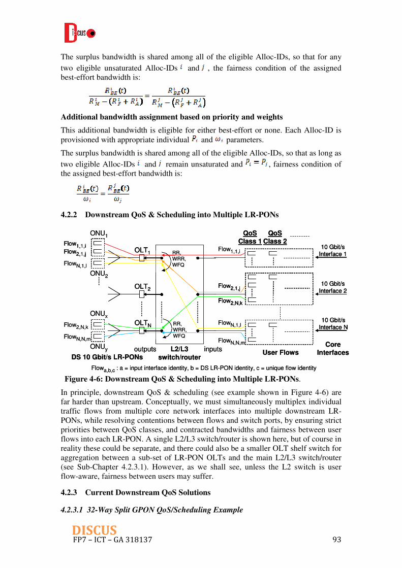
FP7 – ICT – GA 318137 93DISCUS
The surplus bandwidth is shared among all of the eligible Alloc-IDs, so that for any
two eligible unsaturated Alloc-IDs and , the fairness condition of the assigned best-effort bandwidth is:
Additional bandwidth assignment based on priority and weights
This additional bandwidth is eligible for either best-effort or none. Each Alloc-ID is provisioned with appropriate individual and parameters.
The surplus bandwidth is shared among all of the eligible Alloc-IDs, so that as long as
two eligible Alloc-IDs and remain unsaturated and , fairness condition of the assigned best-effort bandwidth is:
4.2.2 Downstream QoS & Scheduling into Multiple LR-PONs
Figure 4-6: Downstream QoS & Scheduling into Multiple LR-PONs.
In principle, downstream QoS & scheduling (see example shown in Figure 4-6) are far harder than upstream. Conceptually, we must simultaneously multiplex individual traffic flows from multiple core network interfaces into multiple downstream LR-PONs, while resolving contentions between flows and switch ports, by ensuring strict priorities between QoS classes, and contracted bandwidths and fairness between user flows into each LR-PON. A single L2/L3 switch/router is shown here, but of course in reality these could be separate, and there could also be a smaller OLT shelf switch for aggregation between a sub-set of LR-PON OLTs and the main L2/L3 switch/router (see Sub-Chapter 4.2.3.1). However, as we shall see, unless the L2 switch is user flow-aware, fairness between users may suffer.
4.2.3 Current Downstream QoS Solutions
4.2.3.1 32-Way Split GPON QoS/Scheduling Example
Flowa,b,c : a = input interface identity, b = DS LR-PON identity, c = unique flow identity
Flow1,1,iFlow2,1,j
ONU1
FlowN,1,l
ONU2
OLT1Flow1,1,i
OLT2
OLTNFlow2,N,k
ONUx
FlowN,N,m
ONUy
QoSClass 1
QoSClass 2
Flow2,1,j
Flow2,N,k
FlowN,1,l
FlowN,N,m
10 Gbit/sInterface 1
10 Gbit/s
Interface 2
10 Gbit/s
Interface N
User FlowsL2/L3
switch/router
inputsoutputsDS 10 Gbit/s LR-PONs
CoreInterfaces
RR,WRR,WFQ
RR,WRR,WFQ
Flowa,b,c : a = input interface identity, b = DS LR-PON identity, c = unique flow identity
Flow1,1,iFlow2,1,j
Flow1,1,iFlow2,1,j
ONU1
FlowN,1,l
ONU2
OLT1OLT1Flow1,1,i
OLT2OLT2
OLTNOLTNFlow2,N,k
ONUx
FlowN,N,m
ONUy
QoSClass 1
QoSClass 2
Flow2,1,j
Flow2,N,k
Flow2,1,j
Flow2,N,k
FlowN,1,l
FlowN,N,m
10 Gbit/sInterface 110 Gbit/s
Interface 1
10 Gbit/s
Interface 2
10 Gbit/s
Interface 2
10 Gbit/s
Interface N
10 Gbit/s
Interface N
User FlowsL2/L3
switch/router
inputsoutputsDS 10 Gbit/s LR-PONs
CoreInterfaces
RR,WRR,WFQ
RR,WRR,WFQ
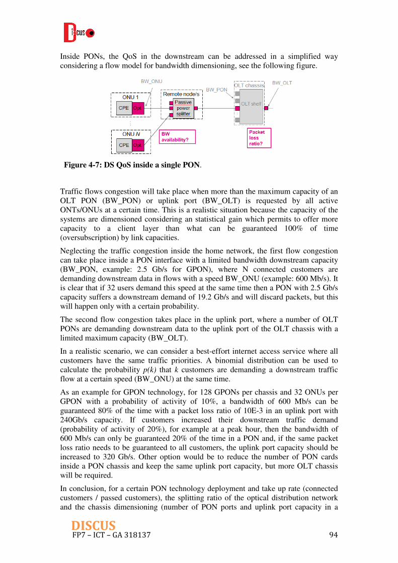
FP7 – ICT – GA 318137 94DISCUS
Inside PONs, the QoS in the downstream can be addressed in a simplified way considering a flow model for bandwidth dimensioning, see the following figure.
Figure 4-7: DS QoS inside a single PON.
Traffic flows congestion will take place when more than the maximum capacity of an OLT PON (BW_PON) or uplink port (BW_OLT) is requested by all active ONTs/ONUs at a certain time. This is a realistic situation because the capacity of the systems are dimensioned considering an statistical gain which permits to offer more capacity to a client layer than what can be guaranteed 100% of time (oversubscription) by link capacities.
Neglecting the traffic congestion inside the home network, the first flow congestion can take place inside a PON interface with a limited bandwidth downstream capacity (BW_PON, example: 2.5 Gb/s for GPON), where N connected customers are demanding downstream data in flows with a speed BW_ONU (example: 600 Mb/s). It is clear that if 32 users demand this speed at the same time then a PON with 2.5 Gb/s capacity suffers a downstream demand of 19.2 Gb/s and will discard packets, but this will happen only with a certain probability.
The second flow congestion takes place in the uplink port, where a number of OLT PONs are demanding downstream data to the uplink port of the OLT chassis with a limited maximum capacity (BW_OLT).
In a realistic scenario, we can consider a best-effort internet access service where all customers have the same traffic priorities. A binomial distribution can be used to calculate the probability p(k) that k customers are demanding a downstream traffic flow at a certain speed (BW_ONU) at the same time.
As an example for GPON technology, for 128 GPONs per chassis and 32 ONUs per GPON with a probability of activity of 10%, a bandwidth of 600 Mb/s can be guaranteed 80% of the time with a packet loss ratio of 10E-3 in an uplink port with 240Gb/s capacity. If customers increased their downstream traffic demand (probability of activity of 20%), for example at a peak hour, then the bandwidth of 600 Mb/s can only be guaranteed 20% of the time in a PON and, if the same packet loss ratio needs to be guaranteed to all customers, the uplink port capacity should be increased to 320 Gb/s. Other option would be to reduce the number of PON cards inside a PON chassis and keep the same uplink port capacity, but more OLT chassis will be required.
In conclusion, for a certain PON technology deployment and take up rate (connected customers / passed customers), the splitting ratio of the optical distribution network and the chassis dimensioning (number of PON ports and uplink port capacity in a
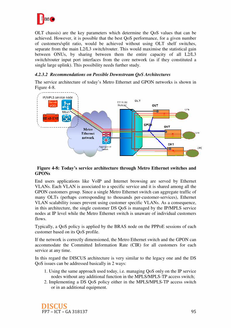
FP7 – ICT – GA 318137 95DISCUS
OLT chassis) are the key parameters which determine the QoS values that can be achieved. However, it is possible that the best QoS performance, for a given number of customers/split ratio, would be achieved without using OLT shelf switches, separate from the main L2/L3 switch/router. This would maximise the statistical gain between ONUs, by sharing between them the entire capacity of all L2/L3 switch/router input port interfaces from the core network (as if they constituted a single large uplink). This possibility needs further study.
4.2.3.2 Recommendations on Possible Downstream QoS Architectures
The service architecture of today’s Metro Ethernet and GPON networks is shown in Figure 4-8.
Figure 4-8: Today’s service architecture through Metro Ethernet switches and
GPONs
End users applications like VoIP and Internet browsing are served by Ethernet VLANs. Each VLAN is associated to a specific service and it is shared among all the GPON customers group. Since a single Metro Ethernet switch can aggregate traffic of many OLTs (perhaps corresponding to thousands per-customer-services), Ethernet VLAN scalability issues prevent using customer specific VLANs. As a consequence, in this architecture, the single customer DS QoS is managed by the IP/MPLS service nodes at IP level while the Metro Ethernet switch is unaware of individual customers flows.
Typically, a QoS policy is applied by the BRAS node on the PPPoE sessions of each customer based on its QoS profile.
If the network is correctly dimensioned, the Metro Ethernet switch and the GPON can accommodate the Committed Information Rate (CIR) for all customers for each service at any time.
In this regard the DISCUS architecture is very similar to the legacy one and the DS QoS issues can be addressed basically in 2 ways:
1. Using the same approach used today, i.e. managing QoS only on the IP service nodes without any additional function in the MPLS/MPLS-TP access switch;
2. Implementing a DS QoS policy either in the MPLS/MPLS-TP access switch or in an additional equipment.

FP7 – ICT – GA 318137 96DISCUS
The first solution simply transfers the DS QoS management under the sole responsibility of the service provider that is the only entity able to avoid misuse of network resources by its own customers. In this case it is mandatory that all service providers perform an accurate capacity design of their VLANs and request that an appropriate CIR is delivered for each VLAN by the network provider. This may require a renegotiation of VLANs characteristics between SPs and NP each time a SP increase its customers base or their bandwidth needs. However, in this case the NP does not need to know the QoS profiles of the SPs customers that may be many thousands, but only the few VLANs characteristics of each SP. Moreover, any possible DS QoS issue affecting one SP does not have any impact on other SPs customers since they are served by other VLANs.
The second solution is more complex and requires:
1. either introducing new equipment to apply DS QoS policies; 2. or augmenting the functions performed by the MPLS/MPLS-TP access switch.
The first option is shown in Figure 4-9.
Figure 4-9: Introduction of DS QoS servers in DISCUS MC node
A server is interposed between the IP/MPLS nodes of each SP and the MPLS/MPLS-TP access switch applying the required QoS policy on all customers belonging to a given SP. This server performs Deep Packet Inspection (DPI) and limits the rate of each single customer flow according to its specific QoS policy.
In this case, a separate server for each SP is advisable in order to avoid a single point of failure affecting multiple SPs.
A non-negligible drawback of this solution is that each SP must provide to the NP a full data base of all customer’s QoS policies to be uploaded in the server. Moreover,

FP7 – ICT – GA 318137 97DISCUS
this data base must be updated every time new customers are added or their QoS requirements are changed.
The second option can be implemented adding DPI functions directly in the MPLS/MPLS-TP access switch. This implies a considerable equipment complexity increment since relatively simple MPLS forwarding functions and Ethernet VPN management must be complemented by IP DPI. The problem of updating customers QoS data bases is even more complex in this case because the MPLS/MPLS-TP access switch must keep and update one separate customer QoS data base for each service provider.
Evidently, there may be a good case to be made for scheduling aggregations of user flows, rather than individual user flows, on complexity and hence possibly on economic grounds.
4.2.3.3 Scheduling of Aggregate Flows (e.g. S-VLANs)
For Residential users, one proposal for Access Network Services is for each OLT to support 4 S-VLANs for each Service Provider (SP) (see Sub-Chapter 2.2.1). Each of an SP’s S-VLANs supports a different end-user application (VoIP, Internet , VoD and IPTV/Broadcast TV). We will assume these are handled as different QoS classes, scheduled in some priority order. In practice, even if VoD and IPTV/Broadcast TV have the same priority, they may have other QoS parameters that are different. We will also assume that each S-VLAN carries all DS user flows for a particular service from one SP to one LR-PON.
However, even if we assume that each SP has its own individual L2/L3 switch input port interface (not shared with other SPs), there would be 4 S-VLAN flows to be buffered and switched from each input port to each output port of the L2/L3 switch. In a conventionally matched and scheduled input-queued packet switch (Figure 4-10), this would correspond to 4 individual flows being aggregated into a single virtual output queue (VOQ). Thus even current DS QoS solutions require more complex scheduling than conventional packet switches. If they simply employed conventional matching and scheduling techniques of input-queued packet switches, which schedule packets buffered in VOQs, the result would be hierarchical scheduling of aggregate flows, which we shall see can be unfair (see Section 4.2.4).
Figure 4-10: Conventional matching & scheduling through an input-queued
packet switch
outputsinputs
A1
AN
VOQ11
VOQNN
1 1
N N
D1
DN
virtualoutputqueues
inputs,
i
outputs,
j
VOQ requests (lengths)
Ri,j
outputsinputs
A1
AN
VOQ11
VOQNN
1 1
N N
D1
DN
virtualoutputqueues
inputs,
i
outputs,
j
VOQ requests (lengths)
Ri,jinputs,
i
outputs,
j
VOQ requests (lengths)
Ri,j

FP7 – ICT – GA 318137 98DISCUS
In conventional matching and scheduling through an input-queued packet switch [18], buffered packets of each VOQ would be forwarded into the output ports, i.e. to each LR-PON OLT interface, using one of several techniques. These include:
a) Using Matching + Time-Slot Scheduling Algorithms: e.g. iSLIP, Frame-Based Scheduling [19], Birkhoff-von Neumann Decomposition
b) Using No Algorithms: e.g. 2-Stage Load-Balancing Switch (fixed TDM scheduling), Parallel Packet Switch (speed-up of 2). (The question arises; when there is no algorithm, is Matching still necessary to ensure an admissible traffic matrix, and thus prevent wasting of switch capacity on packets that will be dropped?)
However, even if conventional matching and scheduling are extended, in order to allow individual S-VLAN flow requests to be handled instead of aggregate VOQ requests (see Section 4.2.5), the S-VLAN flows themselves also represent aggregations of individual user flows within them. Therefore the current DS QoS architecture for Residential services, using 4 S-VLANs per OLT per Service Provider, still represents hierarchical scheduling of aggregate user flows, which remains potentially unfair, as shown in Section 4.2.4.
4.2.4 The Problem of Hierarchical Scheduling
In considering upstream dynamic bandwidth assignment (DBA), FSAN’s GPON Common Technical Specification [20] states clearly that a centralized DBA architecture is fairer than a hierarchical one, as decisions are taken by a single entity. However, in the downstream direction, when only larger aggregations of individual user flows are scheduled across the L2/L3 switch/router, rather than the individual flows themselves, the scheduling becomes hierarchical, and can therefore result in bandwidth fairness problems between users within the LR-PON. For example, a user’s download could a) be granted Assured bandwidth (CIR) left unused by other user flows within the same aggregate flow, and could also b) steal surplus (burst) bandwidth (CIR-PIR) from other users’ flows belonging to different aggregate flows, neither of which it should be entitled to. Both are examples of stealing bandwidth from other user flows. An example of these problems is shown in Figure 4-11.
Figure 4-11: Problem of hierarchical scheduling: bandwidth stealing in QoS-
aware but user flow-unaware aggregation through L2/L3 switch/router. Rate-
FP7 – ICT – GA 318137 99DISCUS
proportional assignment of surplus bandwidth is assumed, with C=242 units of
bandwidth available.
For convenience, the same bandwidth types and priorities are used as in upstream DBA, so the two directions can be compared. Of course different Ethernet QoS classes and bandwidth types may be used in practice. Compared with the DBA reference model in the upstream direction (Section 4.2.1), the resulting aggregate Assured and Non-Assured (A + NA) grants for VOQ11 are too large (22 units), resulting in a bandwidth ratio, for example between flow1,1,1 and flowN,1,2, which is 11 times greater than it should be for both the Assured bandwidth and for rate-proportional assignment of Non-Assured surplus bandwidth. However, if individual user flows are matched and scheduled instead, the correct individual flow grants would be 2, 0, 22 and 218 for flow1,1,1, flow1,1,2, flowN,1,1 and flowN,1,2 respectively, to maintain the correct ratio of unsaturated flows. Thus, with hierarchical (aggregate) scheduling, flow1,1,1 steals 2 units of bandwidth from flowN,1,1 and 18 units of bandwidth from flowN,1,2. Notably, stealing in this example is from users belonging to a different service provider on a different switch input port into the same downstream LR-PON.
These unfairness problems do not occur in the upstream direction within XG-PON, where the DBA reference model and QoS architecture schedule flows fairly from individual users (G.987.3 Section 7 and Section 4.2.1). So there would be asymmetry between US & DS QoS performance in the LR-PON if individual user flows are aggregated together for scheduling hierarchically. In order to obey the same reference model, downstream scheduling across the L2/L3 switch must be not only QoS-aware, but also individual flow-aware, i.e. non-hierarchical and not aggregating individual user flows.
Can the L2/L3 switch/router be scheduled non-hierarchically, to eliminate the directional asymmetry in QoS performance? Section 4.2.5 suggests a potential approach.
4.2.5 A Non-Hierarchical Scheduling Approach
As already stated, for ideal fairness, scheduling needs to be non-hierarchical, non-aggregated, QoS-aware and individual user flow-aware across the L2/L3 switch/router.

FP7 – ICT – GA 318137 100 DISCUS
Figure 4-12: Ideal heuristic matching algorithm for QoS-aware and individual
flow-aware scheduling in input-queued switches?
Hopefully, all the various conventional matching and scheduling methods for packet switches identified in Section 4.2.3.3 could be adapted to achieve this. One possible approach would be to extend frame-based matching through input-queued switches [19], by granting and accepting individual flow requests instead of aggregate VOQ requests. A potential non-hierarchical, QoS-aware and user flow-aware heuristic matching algorithm for this is shown in Figure 4-12. Fairness can be achieved using pointers and various potential pointer up-date rules, or by calculation. When matching is completed, the accepted grants would then need to be time-slot assigned (scheduled) across the switch fabric, using for example the parallel implementation in [21]. Because each ONU can receive the full LR-PON rate C downstream, there is no need to schedule a maximum bandwidth explicitly into each ONU. Therefore DS QoS scheduling can be non-hierarchical, i.e. no separate scheduling into larger and larger aggregations, ensuring full fairness between all user flows and QoS classes across all LR-PONs.
With respect to the iSLIP slot-by-slot matching algorithm [22], frame-based matching [19] offers the benefit of providing longer time intervals between successive requests (queue-length reports) from input ports to output ports, and grants from output ports to input ports. Not only is this potentially capable of “providing performance gains due to statistical multiplexing and temporal correlation between the matchings inside the time frame”, but also is expected to reduce the proportion of the switch’s capacity required to transmit request and grant information. Perhaps this could allow larger switch sizes (numbers of input and output ports) to be supported, as well as allowing the reporting of queue lengths from individual flows within each VOQ, instead of just from aggregate VOQ lengths.
4.2.6 Further Challenges & Issues
Scheduling individual user flows rather than VOQs would greatly increase buffering requirements, as well as the computing complexity of matching, and the proportion of switch capacity required for transmitting request and grant information. These need to be quantified for hardware and software implementation. Even dealing with aggregate

FP7 – ICT – GA 318137 101 DISCUS
S-VLAN flows, rather than VoQs, would increase computing complexity for matching and switch capacity for transmitting requests, even if only one SP occupies each core network interface.
Are there simpler matching/scheduling approaches across the L2/L3 switch/router that could provide acceptable QoS-aware & individual flow-aware performance? For example, could switch structures that use no algorithms, e.g. 2-stage load-balancing switch and parallel packet switch, truly operate without any form of matching algorithm, or perhaps a simplified form, while ensuring QoS and bandwidth fairness between users?
Could the unfairness of bandwidth stealing be quantified, perhaps by simulation (on a modest scale), to see whether the overall impact is really noticeably important?
Bandwidth fairness is relative; scheduling individual user flows is fair to users, but scheduling aggregate flows (e.g. S-VLANs), assuming these are user-unaware, is fair to Service Providers. The choice between the two is political/regulatory, as well as technical/economic. The right balance needs further study.
Scheduling individual user flows, across a single Access switch/router switching fabric, may open up opportunities for removing so many separate switches/routers, and their interfaces, from the architecture. This could potentially save costs and energy consumption, which raises questions of ownership, business models and greenness for further study.
In particular, would the best QoS performance, for a given number of customers/split ratio, be achieved without using OLT shelf switches (in LT and NT cards), separate from the main L2/L3 switch/router? Would it maximise the statistical gain between ONUs, by sharing between them the entire capacity of all L2/L3 switch/router input port interfaces from the core network (as if they constituted a single large uplink)?
Is additional DS scheduling (contention resolution) of individual user flows needed between XGEM-Ports within the LR-PON OLT?
Could Ethernet VLAN scalability issues be resolved by using double-tagging, thus enabling the control of individual customer’s flows through the L2 switch?
Further study of several Broadband Forum documents should shed further light on current DS QoS solutions [23].
Further detailed, agreed QoS specifications for each service are needed, including:
1. QoS parameters per application, both in Access and end-to-end (in each upstream/downstream direction as appropriate):
a. bandwidth (peak, mean), delay (max, mean), jitter (max, mean), packet loss rate.
2. In particular for POTS over voice over IP:
a. is 10 ms acceptable VoIP packet interval?
b. to what value can 1.5 ms Mean Signal Transfer Delay (MSTD) be lengthened with echo cancellation?
c. what is the maximum allowable end-to-end delay for the various Hypothetical Reference Paths? In other words, what levels of user
FP7 – ICT – GA 318137 102 DISCUS
satisfaction (E-model ratings) could DISCUS offer, by removing the Metro network and introducing a flat optical Core network?
3. Signalling requirements and handling for each Application
4. Definition of classes of service (are they the same as the Ethernet QoS priority queues as per 802.1p or the ITU-T FSAN G-PON CTS classes of service?)
5. VLAN Bandwidth Parameters:
a. CIR, CBS, (or GIR, GBS), PIR, PBS, mean session bandwidth, long-term average bandwidth during busy period, guaranteed bandwidth for session duration only (if CAC and resource reservation are used)
b. Surplus bandwidth assignment strategy: rate proportional or priorities/weights, best-effort or better-than-best-effort?
6. Mapping of user applications to classes of service.
7. Maximum number of independent users per Residential ONU, i.e. number of independent flows (VLANs?) per Application per Residential ONU.
a. Also, will each independent user within a Residential ONU have only 1 Application per independent flow (VLAN?)?
It should be noted these issues aforementioned is universal for any switching done in the electronic layer. The aim of WP6 is to design the architecture of the core node, using the existing electronic components for Ethernet switches and IP routers. Therefore it is still under the discussion within DISCUS if the challenges summarized in this Sub-Chapter will be further investigated.
4.3 Design for Open Access
Open access concerns the design and operation of a network such that it supports a degree of freedom to offer a choice of services to the customer (for example, allowing them to choose between service/network providers). It promotes competition and market diversity. In addition, open access networks allow companies to collaborate in the undertaking of the deployment of a network, mitigating risk. For example, the supply of an internet connection to a customer could be divided up into the civil works, network architecture design, deployment and operation and service provisioning tasks. By dividing these tasks between different companies in a collaborative arrangement the risks and investment (at each level) can be compartmentalised, potentially reducing the barrier to market entry to new market entrants outside the initial collaborative agreement. Delivery of service to customers will involve the interaction of multiple actors, which may be performing different roles (see Figure 4-13). For instance, a network provider (NP) may need to lease dark fibre from a physical infrastructure provider (PIP). This may be a self-contained entity (e.g., Stokab scenario in [24]) in which a municipality has installed a dark fibre network, or alternatively it may be only a part of a large vertically integrated monopolist telecommunications provider.

FP7 – ICT – GA 318137 103 DISCUS
Figure 4-13: Roles that must be performed in order to provide a service to a
customer defined in OASE [25]
Furthermore, depending on the scenario, many of these roles could be contained within a single business entity. Several scenarios considered in OASE [25] are shown in Figure 4-14 below.
Figure 4-14: Open access network scenarios considered in OASE [25]. It should
be noted that service provider (SP) can be in plural, i.e. the figure is not locked to
a maximum of three SPs or a single SP per NP in case “e”.
Scenario “a”, is known as a traditional case in the European context which does not support open access. Most of the incumbent operators have currently been regulated into an unbundling of its copper infrastructure, i.e. model “c”. Scenarios “b-f” display some degrees of cooperation in order to provide service. At the most extreme,

FP7 – ICT – GA 318137 104 DISCUS
scenario “f” shows a scenario of a single PIP supporting multiple NPs that in turn support multiple SPs.
Open access is possible on two distinct levels (i.e. between physical infrastructure provider [PIP] and network provider [NP], or between NP and service provider [SP]) utilizing three mechanisms:
1. Fibre open access: allowing NPs to utilize deployed but unused fibre capacity; 2. Wavelength open access: utilizing a wavelength-multiplexing system to allow
signals from multiple NPs to be carried on one fibre, which typically refers to individual wavelength(s) per NP/SP;
3. Bit-stream open access: only differentiating SPs on layer-2 or layer-3 and using one common network infrastructure, which does not support multiple NPs.
The following table summarizes OASE finding of pros and cons for different open access mechanisms.
Table 4-2: Pros and cons for different open access mechanisms
Mechanisms Pros Cons
Fiber Open Access
1) In case this is a fiber rich network (i.e. multiple fibers to each user), it is a simple solution. 2) It is technology agnostic, what makes it perfectly future proof. It allows the ultimate level of choice of network technology employed later on. 3) Based on the use of different fibers, there is a good isolation of traffic between users and between operators, which gives excellent security and control. It allows the ultimate level of control over low-level channel parameters.
1) There is a lot of sharing in comparison to concurrent vertical operators, which leads to higher costs (both higher infrastructure cost and lower energy efficiency). 2) Less suitable for fiber poor scenarios. Though, the cost for installing a couple of extra fibers is negligible in comparison to the trenching and ducting costs, and should therefore be considered anyhow when setting up a deployment planning.
Wavelength Open Access
1) Wavelength open access is a fairly cheap and easy option (depending on technology), by installing limited extra equipment to divide the wavelengths among the NPs on the central office side, and among the end-customers on the CPE side. 2) Well suited for fiber poor scenarios. No extra fibers should be installed to provide this option (in contrary to open access on fiber level), which makes it cheaper if installed afterwards.
1) This way of open access is not technology-agnostic. Dependent on the PON architecture used, different equipment should be installed, and should therefore also be replaced when switching to next-generation options. 2) Quite inflexible – harder NP migration for the customers in many architectures (end-user) 3) Isolation issue: it happens in any power-splitter based PON architecture that one ONU affects other ONUs that belongs to another NP domain. It could also make fault identification become difficult. Who is to blame for the fault?

FP7 – ICT – GA 318137 105 DISCUS
Bit-stream Open Access
1) Dynamic service models – bit streaming, i.e. easy introduction of new services to all customers 2) Simplified administration and management. No problems arise from the co-existence of multiple operators’ equipment.
1) This is only for a single NP mode, leading to low infrastructural sharing. 2) Monitoring for a certain SP is lacking, i.e. the open access network is a “black box”. 3) Lack of control over the lower level parameters may prevent them from offering QoS or similar service differentiation techniques. 4) Security – if you don’t have high isolation between SPs, co-ordination is needed for security reasons.
The current DISCUS metro/core node architecture offers bit-stream based open access mechanism supporting multiple service providers. However, as the general disadvantages for bit-stream scheme mentioned above, we define several issues to be tackled in the future to improve design for open access:
1) Co-existing of multiple NPs (still needed due to regulation) 2) Co-ordination/isolation among SPs 3) Offering SPs lower layer parameters for better QoS
Furthermore, it should be noted that it is very challenging to make the current DISCUS node architecture support wavelength or fiber open access (which is easy to host multiple NPs). So far all the traffic from both access and core segments need to pass optical space switch, which offers flexibility to support various DISCUS services listed in Section 2. For multi-NP environment, this optical space switch could bring several serious issues, i.e. who will own this active equipment, who could be a proper entity to operate it, etc. These challenges will be tackled during the remainder of the project.
4.4 Optical Power Budget
For the standard LR-PON traffic (bi-directional OLT/ONT transmission) the power budget presented in D2.1 has taken into account the preliminary configuration of the metro/core node including the expected losses of the various components (wavelength mux/demux, optical switch, etc.). Due to the presence of optical amplifiers at the ingress/egress of the node, small deviations in the component losses can be accommodated with no impact on the overall performance of the link, which is mostly limited by the access and metro portions of the LR-PON.
Using the functionalities provided by the optical switch high capacity dedicated circuits for high end applications requested by enterprise customers could also be routed in the optical layer to another LR-PON or to the core segment of the network (as discussed in Sub-Chapter 2.2) without OEO conversion in the OLT. The main challenge in order to enable this application is the differential loss in the access part of the LR-PON. If the signal from one LR-PON is routed directly to another LR-PON the dynamic range seen by the receiver at the user end would be, in dB, twice the dynamic range that the OLT would experience during normal LR-PON operation. If the signal is routed to the core network, the power will need to be equalised in order to maintain flatness of the channel launched in the core.

FP7 – ICT – GA 318137 106 DISCUS
In order to address this issue the metro/core node will have to include additional components. Figure 4-15 is showing the DISCUS architecture enabling the direct connection at optical level between two users on different LR-PONs connected to the same metro/core node in the case of a dense urban area. The signal from one upstream channel of the LR-PON-1 is routed through the optical switch to a variable gain amplifier which is performing power levelling of the signal before it re-enters the optical switch and it is then routed as a downstream channel of the LR-PON-2. The figure is also showing the amplifier required by the path going from LR-PON-2 to LR-PON-1. The amplifier could simply be a standard single channel EDFA operated in power control mode. The same amplifier could also be used to route the dedicated channel to the core network adjusting the power to requirement of the core link. In this preliminary report we have examined the power and OSNR budget only in the case of an all-optically routed channel between two LR-PONs connected to the same MC node. A more comprehensive study will be presented in D6.5.
4
x
4
OLT
LE
M/C Node
4
x
4
LE
Optical
Switch10 km
10 km90 km
90 km
Optical
Switch
Variable Gain EDFAs
Amplified Splitter
Amplified Splitter
Tx
Rx T
F
Tx
Rx T
F
ONT
ONT
LR-PON-1
LR-PON-2
Figure 4-15: DISCUS architecture enabling the direct connection at optical
level between two users on different LR-PONs for a dense urban area.
We assume that the additional variable gain EDFA in the metro/core node has a noise figure of 5.5dB as the other EDFAs in the LR-PON and also that it is operated in power controlled mode with an output power of +5dBm. All the other parameters are assumed to be the same as in D2.1. Figure 4-16 shows the calculated power and the final OSNR of the loud and soft signal as they travel through the components of LR-PON-1, the metro/core node, and LR-PON-2, where both LR-PONs have a split of 512. It should be noted that since the traffic is continuous we refer to soft/loud signals rather than bursts.

FP7 – ICT – GA 318137 107 DISCUS
-40
-30
-20
-10
0
10
20
Sig
na
l P
ow
er
[dB
m]
'Loud' Signal
'Soft' Signal
PTX = +5 dBm
OSNR = 40 dB
+ 15 dBm
Tx Rx
PRX = -27.80 dBm
OSNR = 17.36 dB
PRX = -13.55 dBm
OSNR = 29.01 dB
LR-PON-1 LR-PON-2 M/C Node
Figure 4-16: Power and the final OSNR of the loud and soft signal as they travel
through the components of LR-PON-1, the metro/core node, and LR-PON-2, for
a dense urban area and a split of 512.
As we can see the worst case is represented by the soft signal which travels through both LR-PONs with the maximum loss and hence has the lowest received power and OSNR. For a 10Gb/s link assuming the use of an APD and of FEC the receiver should be able to operate, although with very small or no margin depending on the implementation and FEC. In the case of a 100Gb/s link using DP-QPSK and coherent detection the required OSNR for operation at 3.8e-3, which can be corrected by commercially available FEC, is theoretically around 12dB, while experimental demonstration have been shown to be able to work with a required OSNR of around 15dB [27]. A 100Gb/s channel should thus be able to operate with margin.
Figure 4-16 is showing the case where the signal is routed from/to LR-PONs in sparsely populated rural area using a distributed split in multiple LEs. Like in the previous case power levelling is necessary in the metro/core node, which can be obtained using a single channel EDFA in power control mode. Figure 4-18 is showing the calculated power and the final OSNR of the loud and soft signal as they travel through the components of LR-PON-1, the metro/core node, and LR-PON-2, with the LR-PONs topology shown in Figure 4-17 and a total split of 640. Also in this case the limiting factor is the soft signal, which is however showing a higher received power and OSNR compared to the previous case. This would correspond to a higher margin for both 10Gb/s link and the DP-QPSK 100Gb/s link.

FP7 – ICT – GA 318137 108 DISCUS
30 km
30 km
30 km
30 km
30 km
30 km
10 km
OLT
M/C Node
Optical
SwitchOptical
Switch
Variable Gain EDFAs
Amplified Splitter
Tx
Rx T
F
ONT
Tx
Rx T
F
ONT
LR-PON-1
LR-PON-2
Figure 4-17: DISCUS architecture enabling the direct connection at optical
level between two users on different LR-PONs for a sparsely populated rural
area using a distributed split in multiple local exchanges.
-35
-30
-25
-20
-15
-10
-5
0
5
10
15
Sig
na
l Po
we
r [d
Bm
]
'Loud' Signal
'Soft' Signal
+ 12 dBm
PTX = +5 dBm
OSNR = 40 dB
PRX = -13.75 dBm
OSNR = 31.29 dB
PRX = -27.80 dBm
OSNR = 19.25 dB
Tx Rx
LR-PON-1 LR-PON-2 M/C Node
Figure 4-18: Power and the final OSNR of the loud and soft signal as they travel
through the components of LR-PON-1, the metro/core node, and LR-PON-2, for
a sparsely populated rural area using a distributed split in multiple Les and a
total split of 640.
FP7 – ICT – GA 318137 109 DISCUS
4.5 Energy Efficiency
Energy consumption in telecommunication networks has become a significant problem during the last few years. The information and communication technology (ICT) sector amounts to 8% of the total energy consumption worldwide and communication networks are responsible for 30% of energy consumed by ICT [28]. Many energy efficient mechanisms have been proposed (e.g. [29][30][32]), which have both multiple benefits and levels of consideration. For example, on one hand they could reduce the carbon footprint of individual devices up to metropolitan and national deployments, as well as the economic benefits to both end-users and corporate institutions as they consume less energy. On the other hand, some of them could introduce non-negligible impact on the system and network performance (e.g., delay, blocking probability, quality of transmission, reliability, etc.). Four groups of principles have been summarized in communication network [33], which could bring a significant improvement in overall energy efficiency. They are: 1. Improved inherent energy-efficiencies as offered by electronics technologies (more efficient CMOS technologies, high temperature operation of integrated circuits) 2. More sophisticated management and exploitation of network resources (source and channel coding, multi-layer traffic engineering (MLTE), powering down, sleep/idle modes and burst-mode operation. 3. The inherent energy efficiencies as offered by optics technology solutions such as optical bypassing, coherent detection, and polarization multiplexing. 4. More environmentally sustainable approaches to network design such as micro-power generation, increased reliability and robustness of network equipment. Among these four general categories, we consider optical bypass, MLTE, powering down and sleep/idle mode are the most relevant principles suitable for DISCUS optical network architecture design. Thereof, we take into account these three principles in this sub-chapter and discuss the opportunities and challenges of employing these energy saving mechanisms in DISCUS metro/core node design. Optical bypass – avoiding OEO, OE or EO conversions
Current IP routers still require full OEO conversion. According to [33], if at least half the number of nodes could be optically bypassed by a packet traversing the network this would represent at least a 50% saving in IP router energy. One of the key characteristics of DISCUS architecture is to avoid OEO, OE or EO conversions and support flat optical core, where wavelength paths are set up across the network interconnecting the DISCUS metro/core nodes. Thus, traffic passing through a node could be transparent in the optical domain and does not require any processing in electronic layers. The DISCUS architecture aims to achieve optical bypass by proposing a fully wavelength-switched core network. Electronic packet processing is only used for adding or dropping traffic to metro/core nodes, while all express traffic is optically switched at every node. Since full meshed networks require a number of wavelength links equal to the square of the number of nodes, the size of a wavelength-switched (or optical) island is upper-bounded. One of the main argument against a full wavelength mesh is that traffic between nodes tends to be non-uniform in current network, so while point-to-point wavelength links are justified between larger nodes requiring capacity of at least 10Gb/s (which

FP7 – ICT – GA 318137 110 DISCUS
we can assume the smallest granularity of link capacity in the core), an additional packet processing layer is required in the network to groom traffic from smaller nodes. We believe however that the DISCUS architecture can play an important role in spreading traffic more uniformly among metro/core nodes. Since each metro/core node can serve a maximum of 500 thousand to one million end users and can cover an area of about 100km in radius, it is easy to envisage scenarios, especially in Europe, where most metro/core nodes will reach their maximum size (i.e., where there is a population density between 30 and 60 km2). Following well-known results of traffic gravity models [34], stating that traffic between any two nodes is proportional to their size, we can assume that a more uniform distribution of metro/core node size will produce a more uniform traffic matrix among them, strengthening the argument in favor of a flat optical core network. In DISCUS however we want to design for the 100%, i.e., propose an architecture that can be molded to adapt to almost every geographical scenarios. Thus, in order to address situations where certain geotypes do not make it possible to aggregate half million customers on metro/core nodes, we consider the possibility of grooming traffic on a subset of DISCUS nodes. In this two-level hierarchy, smaller metro/core node only connect to two (i.e., for resiliency purpose) larger aggregator nodes. The full wavelength mesh is then only established among these larger nodes. Cost-optimization studies will be carried out to understand the optimal trade-off between flat and hierarchical core networks for different geotypes. It should be noticed that another very relevant scenario where such trade-off will be considered is that of migrating from legacy network (with highly non-uniform traffic) to a DISCUS network. From a technological point of view, there are at least, two requirements on DISCUS node design to enable transparent switching of express traffic: 1) reserving sufficient ports in optical space switch for optical bypass traffic and 2) proper interconnecting with Flexgrid WSS equipment in case supporting elastic resource allocation. Furthermore, as stated in Chapter 2, enterprise customers may require high capacity dedicated circuits towards the core segment. These demands can be served directly by optical circuits that flow transparently trough LR-PON and core network segments via optical space switch at DISCUS node. It offers opportunity to bypass L2/3 switches in DISCUS node and hence brings additional energy saving. On the other hand, it should be noted that full flexibility (i.e. any input port can be connected to any other output port) of optical space switch would be highly required to realize optical bypass between LR-PON and core network segments. As pointed out in sub-chapter before, it is an obvious tradeoff between full flexibility and scalability of switch. Currently, the maximal size of switch matrix based on Polatis beam steering technology is 192x192. Based on two sided three-stage clos structure, the size of switch supporting non-blocking could be extended up to 18336x18336 (i.e. 18336=96x191). However, it means several hundreds of Polatis switch modules are needed, which may significantly increase the complexity of operational aspects (e.g. control, footprint, fault management, maintenance, etc.). In the future, we need to design new DISCUS node architecture, which could optimize the size of optical switch while keeping a sufficient level of flexibility in order to support various DISCUS services, in particular for dense urban case (such as London). Multilayer Traffic Engineering (MLTE)

FP7 – ICT – GA 318137 111 DISCUS
In situations where, because of non-uniformity of traffic, a full mesh of wavelength channels is not economically viable, MLTE grooming can be used to reduce energy consumption. MLTE exploits traffic statistics to re-route traffic away from under-utilized nodes (e.g. the traffic rate is below a pre-defined low-level threshold) and groom the traffic onto relatively more popular router nodes. The routers in those relatively under-utilized nodes can then be switched into an idle state. 3dB reduction on energy consumption is plausible [33]. In order to apply this kind of energy efficient schemes, the IP/MPLS router of DISCUS node should support a “low power” state (i.e. powering-down or sleep/idle-mode, see sub-chapter below) as well as fast switching between working and low power mode. Powering-down, sleep/idle-mode This type of mechanisms means a “low power” state (i.e. powering-down or sleep/idle-mode) of network devices that can be utilized in low traffic conditions. Some results [33] have shown that up to 3.4 dB energy saving can be obtained (depending on traffic situation). Besides, energy saving could be improved up to around 6 dB by combining with MLTE aforementioned. We can expect that an introduction of these power efficient schemes in DISCUS metro/core node is also beneficial in terms of reduced energy consumption. On the other hand, this type of power efficient schemes might save energies at the expense of not only an increase of the equipment complexity but also a negative effect of the overall network performance. These tradeoffs have been addressed in the literature in the case of both core and access networks where DISCUS node are supposed to be connected. A number of works (e.g. [29][30]) tried to find the best way to mitigate the performance (including blocking probability, delay, etc.) degradation while still optimizing energy savings. Furthermore, a frequent switching between a working and a sleep state may also increase the risk for equipment failure, which in turn translates to higher operational expenditures in terms of an additional reparation cost and potential service interruption penalties [31]. The degradation on reliability performance is particularly of importance in the DISCUS metro/core node where a huge number of end users are connected (and also large amount of traffic is involved). Therefore, we will further explore this issue in DISCUS project and try to identify its possible impact on DISCUS metro/core node.
4.6 Cost
The cost is a key factor to be considered for DISCUS MC node design. The related cost model will be developed in WP2. Some recent results of ICT STRONGEST project confirmed economic viability of MPLS-TP over DWDM as core packet transport technology. The future work should also be carried out to further reduce the cost on the modules in MC node dealing with the access segment as well as the end-to-end solution (which covers both access and core parts.)
In ICT STRONGEST deliverable D2.4, two alternative packet over DWDM technologies have been compared:
• IP/MPLS over DWDM (i.e. the technology used today)
• MLPS-TP over DWDM (i.e. the packet transport technology envisaged for DISCUS core network)
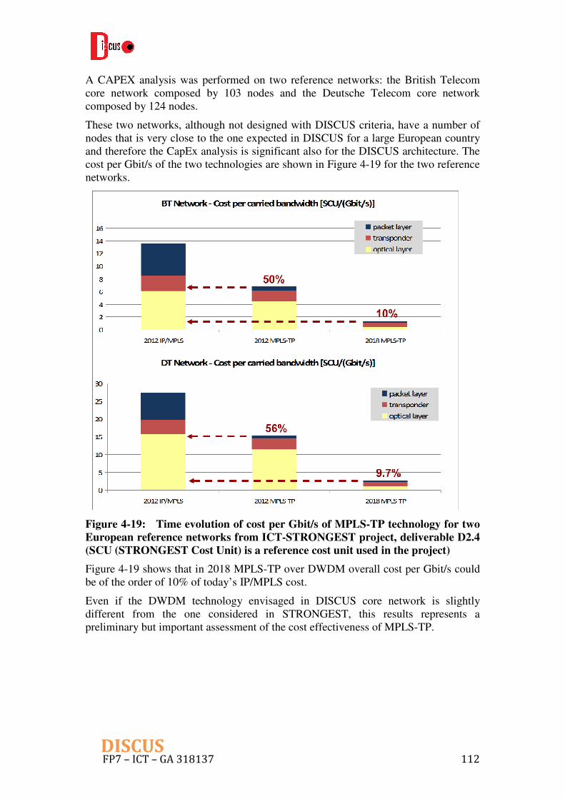
FP7 – ICT – GA 318137 112 DISCUS
A CAPEX analysis was performed on two reference networks: the British Telecom core network composed by 103 nodes and the Deutsche Telecom core network composed by 124 nodes.
These two networks, although not designed with DISCUS criteria, have a number of nodes that is very close to the one expected in DISCUS for a large European country and therefore the CapEx analysis is significant also for the DISCUS architecture. The cost per Gbit/s of the two technologies are shown in Figure 4-19 for the two reference networks.
Figure 4-19: Time evolution of cost per Gbit/s of MPLS-TP technology for two
European reference networks from ICT-STRONGEST project, deliverable D2.4
(SCU (STRONGEST Cost Unit) is a reference cost unit used in the project)
Figure 4-19 shows that in 2018 MPLS-TP over DWDM overall cost per Gbit/s could be of the order of 10% of today’s IP/MPLS cost.
Even if the DWDM technology envisaged in DISCUS core network is slightly different from the one considered in STRONGEST, this results represents a preliminary but important assessment of the cost effectiveness of MPLS-TP.
FP7 – ICT – GA 318137 113 DISCUS
5 Conclusions
In the deliverable, we have reported the preliminary outcome resulting from Task T6.1, “metro/core node architecture design”. First, a set of network services have been identified in order to derive the functions required at DISCUS MC node. They are divided into two major categories, namely end user-oriented and core-oriented, which highly impact on the MC node modules handling the traffic from/to LR-PON and optical flat core segments in DISCUS architecture, respectively. Moreover, some preliminary requirements on quality of service (QoS) are provided, which could be interpreted to the basic criteria for node architecture design.
Then the overall DISCUS MC node design is refined based on the initial work depicted in D2.1 by containing the functions for different layers supporting the specified DISCUS network services. The considered functions include optical switching, optical transport towards optical flat core, OLT towards LR-PON dealing with time and wavelength division multiplexing, as well as the L2/L3 MPLS/MPLS-TP based switching. Besides, the corresponding interfaces to control plane are also defined along with several scenarios and functionalities that are planned to be implemented in the DISCUS OpenFlow based control plane. It should be noted that the optical space switch used in DISCUS MC node offers a transparent optical layer that the fibre links towards both access and core segments as well as electronic layers (e.g. L2/L3 switches) could flexibly connect to. Both two-sided and single-sided optical switch based on beam steering technology are considered to realize this feature. The former one has less flexibility than the latter one, while its maximum size could be as twice as the second one. The preliminary MC node dimensioning model covers the two-sided optical switch and could be extended to the other configurations. According to the results based on UK scenario, by using the current beam steering technology largest two-sided switch matrix size (i.e. 192x192 optical ports) bandwidth up to 50Mb/s per user can be provided on the average MC node coverage of 300,000 premises served. To go beyond this bandwidth per user and/or node coverage, larger switch matrices are required. It is possible with the beam steering technology but requires further development with matrix size up to possibly 500x500.
Meanwhile, the background bases have been presented for the different architectural aspects with respect to resiliency, QoS, open access, optical power budget, energy efficiency, and cost. Some preliminary performance assessment has been carried out, based on which several challenges and issues (in particular in resiliency and open access) have been identified to be further investigated during the remainder of the project in order to improve the design of DISCUS MC node architecture.
It should be noted that this document is a first report of Task T6.1 on the specifications of the DISCUS MC node architecture. Due to the early stage of this task, the work presented here should be considered an initial investigation and will be subject to enhancement over the course of the task. Apart from the work done within WP6, the future study on DISCUS MC node design will also interact with the investigations of service requirement, cost and energy models (from WP2), LR-PON components (developed in WP4 and WP5), and backbone network control plane (designed in WP7). The final overall DISCUS MC node structure will be reported in

FP7 – ICT – GA 318137 114 DISCUS
Deliverable D6.5 (due Month 29 of the project).

FP7 – ICT – GA 318137 115 DISCUS
6 Abbreviations
A Assured
AAA Authentication, Authorization and Accounting
ABNO Application-Based Network Operations)
API Application Programming Interfaces
AR Access Router
AWG Arrayed Waveguide Grating
BRAS Broadband Remote Access Server
BSC Base Station Controller
BTS Base Transceiver Station
C3PO Colourless and Coolerless Components for low Power Optical Networks
CAPEX Capital Expenditures
CC Customer Configurable
CE Customer Edge
CIR Committed Information Rate
CO Central Office
CoS Class of Service
CP Channel Pair
CPE Customer Premises Equipment
DBA Dynamic Bandwidth Allocation
DISCUS DIStributed Core for unlimited bandwidth supply for all Users and Services
DP-16QAM Dual Polarization-16-ary Quadrature Amplitude
Modulation
DP-BPSK Dual Polarization-Binary Phase Shift Keying
DP-QPSK Dual Polarization-Quadrature Phase Shift Keying
DPI Deep Packet Inspection
DS DownStream
DSP Digital Signal Processing
DWDM Dense Wavelength Division Multiplexing
EoMPLS Ethernet over MPLS
EPC Evolved Packet Core
FP7 – ICT – GA 318137 116 DISCUS
FEC Forward Error Correction
FIT Failure In Time
FRR Fast Re-Route
GPON Gigabit-capable Passive Optical Network
GSM Global System for Mobile
H-VPLS Hierarchical Virtual Private LAN Service
HSI High Speed Internet
ICT Information and Communication Technology
IGMP Internet Group Management Protocol
IP Internet Protocol
IPoE IP over Ethernet
ISSU In Service Software Upgrade
LR-PON Long Reach-Passive Optical Network
L1 Layer 1
L2 Layer 2
L3 Layer 3
LAN Local Access Network
LFA Loop Free Alternate
LI Line Interface
LSP Label Switched Path
LTE Long-Term Evolution
MAC Media Access Control
MC Metro-Core
MLTE Multi-Layer Traffic Engineering
MPLS MultiProtocol Label Switching
MPLS-TP MultiProtocol Label Switching - Transport Profile
MSTD Mean Signal Transfer Delay
MTBF Mean Time Between Failure
MTTR Mean Time To Repair
NA Non-Assured
NGN Next Generation Network
NIC Network Interface Card
NNI Network-to-Network Interface
NO Network Operator

FP7 – ICT – GA 318137 117 DISCUS
NOP Network Operating System
NP Network Provider
NT Network Termination
OAM Operation Administration and Maintenance
OCh Optical Channel
ODN Optical Distribution Network
OLT Optical Line Terminal
ONT Optical Network Terminal
ONU Optical Network Unit
OPM Optical Performance Monitoring
OPU Optical channel Payload Unit
OSA Optical Spectrum Analyzer
OSM Optical Switch Module
OSS/NMS Operation Supporting System/Network Management System
OTU Optical channel Transport Unit
P2MP Point to MultiPoint
P2P Point to Point
PC Private Circuit
PCC Policy and Charging Control
PCE Path Computation Element
PCEF Policy and Charging Enforcement Function
PCR Program Clock Reference
PCRF Policy and Charging Rules Function
PE Provider Edge
PHP Penultimate Hop Popping
PIP Physical Infrastructure Provider
PLR Packet Loss Ratio
PPPoE Point-to-Point Protocol over Ethernet
PW Pseudo-Wires
QoS Quality of Service
RBD Reliability Block Diagram
ROADM Reconfigurable Optical Add-Drop Multiplexer
RSVP Resource ReserVation Protocol
SCh Super Channel

FP7 – ICT – GA 318137 118 DISCUS
SD Software Decision
SDN Software Defined Network
SOHO Small Office/Home Office
SP Service Provider
TC Transmission Convergence
TCP Transmission Control Protocol
TDM Time Division Multiplexing
TE Traffic Engineering
TFF Thin Film Filter
TWDM Time and Wavelength Division Multiplexing
UK United Kingdom
UMTS Universal Mobile Telecommunication System
UNI User Network Interface
US UpStream
VLAN Virtual Local Access Network
VoIP Voice over IP
VoD Video on Demand
VOQ Virtual Output Queue
VPLS Virtual Private LAN Service
VPN Virtual Private Network
VRF Virtual Routing and Forwarding
VSI Virtual Service Instance
WDM Wavelength Division Multiplexing
WM Wavelength Mux/demux
WSS Wavelength Selective Switching

FP7 – ICT – GA 318137 119 DISCUS
7 References
[1] ITU-T G.114. International telephone connections and circuits. One way transmission time, May 2003.
[2] Troubleshooting IP Video QoS (White Paper), JDSU, 2005. [3] Technical Report TR-156 issue 3. Using GPON Access in the context of TR-101,
Broadband Forum, Nov. 2012. [4] 3GPP TS 23.203 Release 8: Policy and Charging control architecture, Jul. 2012.
[5] ITU-T Recommendation G.989.2; “40-Gigabit-capable passive optical networks (NG-PON2): Physical media dependent (PMD) layer specification”, to be released in 2013/2014
[6] W. Pöhlmann, et al., "Performance of Wavelength-Set Division Multiplexing PON-Upstream in the O-band with Optical Preamplification", paper Tu.4.B.2, 38th ECOC, Amsterdam, 2012
[7] N. Leymann, et al., “Seamless MPLS Architecture, draft-ietf-seamless-mpls-02”, Oct. 2012
[8] ITU-T Recommendations G.8110, MPLS layer network architecture, March 2005 [9] ITU-T G.8110.1, Architecture of the Multi-Protocol Label Switching Transport
Profile layer network, Nov. 2012 [10] IETF Standard RFC5654, Requirements of an MPLS-TP Transport Profile,
Sep. 2009 [11] IETF Standard RFC5860, Requirements for Operation, Administration and
Maintenance (OAM) in MPLS Transport Profile, May 2010 [12] IETF Standard RFC5921, A Framework for MPLS in Transport Networks,
Jul. 2010 [13] IETF Standard RFC6371, Operation, Administration and Maintenance
Framework for MPLS-based Transport Networks, Sep. 2011 [14] IETF draft-martinotti-mpls-tp-interworking-02, Interworking between MPLS-
TP and IP/MPLS, Jun. 2011 [15] IETF individual draft, A PCE-based Architecture for Application-based
Network Operations, Dec. 2012 [16] H. C. Leligou, et al., “Efficient Medium Arbitration of FSAN-compliant
GPONs,” International Journal of Communication Systems Vol. 19, pp.603–617, Jun. 2006
[17] ITU-T Recommendation G.987.3, 10-Gigabit-capable Passive Optical Networks (XG-PON): Transmission Convergence (TC) specifications, Oct. 2010
[18] A. Goel, et al., “Network Algorithms: Techniques for Design and Analysis,” ACM SIGCOMM, San Diego, California, 2001
[19] A. Bianco, et al.,“Frame-based matching algorithms for input-queued switches,” High Performance Switching and Routing HPSR, 2002.
[20] A. Cauvin, et al., "Common Technical Specification of the G-PON System among Major Worldwide Access Carriers," Communications Magazine, IEEE , vol.44, pp.34-40, Oct. 2006

FP7 – ICT – GA 318137 120 DISCUS
[21] T. T. Lee, et al., “Parallel Routing Algorithms in Benes-Clos Networks,” IEEE INFOCOM, 1996.
[22] N. McKeown, “The iSLIP Scheduling Algorithm for Input-queued Switches,” IEEE/ACM Transactions on Networking, Vol. 7, pp. 188–201, Apr. 1999.
[23] Broadband Forum documents: TR-156, Section 5.2 (QoS in PONs); TR-101i2, Sections 3.3, 4.2 & 5.2 (Ethernet/ATM); TR-059, Section5 (QoS-enabled IP).
[24] Stokab, "Official Website" (2011). Retrieved from http://www.stokab.se/.
[25] OASE Deliverable 6.1, "Overview of Tools and Methods and Identification of Value Networks", Oct. 2010.
[26] OASE Deliverable 6.3, " Value Network Evaluation", Dec. 2012.
[27] K. Roberts, et al., “Performance of Dual-Polarization QPSK for Optical Transport Systems,” J. Lightwave Technol., 27, 3546-3559 (2009).
[28] P. Chowdhury, et al., “Building a Green Wireless-Optical Broadband Access Network (WOBAN)”, IEEE/OSA JLT, vol.28, no.16, pp.2219- 2229, Aug. 2010.
[29] P. Wiatr, et al., “Green WDM-PONs: Exploiting Traffic Diversity to Guarantee Packet Delay Limitation”, ONDM 2013, Brest, France, Apr. 2013.
[30] P. Wiatr, et al., “Power Savings versus Network Performance in Dynamically Provisioned WDM Network”, IEEE Com. Magazine, vol.50, no.5, pp.48-55, May 2012.
[31] P. Wiatr, et al., “Energy Saving in Access Networks: Gain or Loss from the cost Perspective?”, ICTON, Cartegena, Spain, Jun. 2013.
[32] A. Jirattigalachote, et al.,”Dynamic provisioning strategies for energy efficient WDM networks with dedicated path protection”, OSN, Special issue on Green Communication and Networking, vol.8, no. 3, pp.201-213, July 2011.
[33] IP-STRONGEST Deliverable D2.4 “Final results on novel packet based Petabit transport networks fulfilling scalability, quality, cost and energy efficiency requirements”, Dec. 2012.
[34] A. Medina, et al., “Traffic matrix estimation: Existing techniques and new directions”, ACM SIGCOMM, Aug. 2002.

FP7 – ICT – GA 318137 121 DISCUS
8 APPENDIX I
We consider Polatis optical matrix switches for DISCUS project. It utilizes opposing 2-D arrays of fibre-pigtailed collimators which are individually steered by piezoelectric bimorphs via a low-stress flexure pivot. The piezoelectric bimorph moves in two dimensions in response to applied voltages. The pointing angles of the actuators are monitored by high accuracy capacitive position sensors. During production calibration, the actuator-steered collimators are trained to find opposing collimators and thus create optical connections from one fibre to another. The pointing angles are optimized, measured and the values are entered into a lookup table. When a switch connection is commanded, the values are extracted from the lookup table and the actuators are driven to and held in the correct position by a digital control loop.
Figure 8-1: Polatis Series 6000 Optical Switch Tray
192x192 is the largest size of switch matrix that could be achieved by the state of the art, while the switch matrix with the size beyond, e.g. 500x500, is under the development. Figure 8-1 shows currently commercialized Polatis Series 6000 optical swtich tray with the size of 192x192. It is non-blocking all-optical switch and could be used in telecom and data center networks. In this switch, optical connections can be switched without light being present on the fiber. This allows operators to pre-provision paths, as well as to perform intelligent network monitoring and test, over lit or dark fiber. This technology can also switch bi-directional optical signals. The performance specifications of the 192x192 switches are shown in Table 8-1.

FP7 – ICT – GA 318137 122 DISCUS
Table 8-1: Performance specifications for the dual sided Polatis 192x192 optical
switch
Performance ParametersPolatis 192x192 Optical Switch
Specifications
Maximum Matrix Switch Size (NxN) 192x192
Typical Insertion Loss1 1.2dB
Maximum Insertion Loss1 2.2dB
Loss Repeatability +/-0.1dB
Dark Fiber Switching Yes
Bi-Direction Optics Yes
Max Switching Time 25ms
Operating Wavelength Range 1260-1675nm
Return Loss (with APC connectors) >50dB
Maximum Optical Input Power +27dBm
Electrical and MechanicalPolatis 192x192 Optical Switch
SpecificationsFiber Type Single Mode
Control Languages TL1, SCPI, HTML and SDN/OpenFlow
User Interfaces RJ45 Dual Ethernet 10/100 Base T and USB
Power 100-240 VAC 50/60 Hz
Power Consumption 60W
1. Measured using the 3 patch-cord method as defined in ANSI/TIA/EIA-526-7-1998
All parameters are measured excluding connectors at 1550nm and 20oC with an unpolarized
Besides, It has been demonstrated that a highly reliable core architecture with an accumulated piezo actuator life of system in the field exceeds 1 billion fiber port-hours with no reliability-affecting failures of the core technology. While the FIT (Failure In Time) rates are very low overall for the fielded systems, in order to ensure carrier-class performance and appropriate system redundancy and resilience, the optical switch matrix is being further enhanced to incorporate additional system redundancy and logic. The switch has a high reliability distributed architecture that eliminates the possibility of any single point of failure disabling the entire switch and includes dual hot-swap power supplies. In addition, the switch software can be easily upgraded in the field without affecting in-service switch operations.
Building on proven field success for resiliency and reliability, the switch has been specifically designed to meet the reliability requirements of data center and telecom applications. Historically, we have experienced no failures with the piezo-beam steering elements in the optical cores and the design includes field replacement components enabling carrier class Mean Time To Repair (MTTR).

FP7 – ICT – GA 318137 123 DISCUS
Figure 8-2: – Series 6000 Resilient Switch Architecture
As mentioned previously, Polatis also has single-sided switch. The performance specifications of the 192xCC single-sided switch are shown in the following table.
Table 8-2: Performance specifications for the single-sided Polatis 192xCC optical
switch
Performance ParametersPolatis 192xCC
1
Optical Switch Specifications
(Where any port can connect to any other port)
Maximum Matrix Switch Size (N) 192 ports
Typical Insertion Loss2 1.2dB
Maximum Insertion Loss2 2.2dB
Loss Repeatability +/-0.1dB
Dark Fiber Switching Yes
Bi-Direction Optics Yes
Max Switching Time 25ms
Operating Wavelength Range 1260-1675nm
Return Loss (with APC connectors) >50dB
Maximum Optical Input Power +27dBm
Electrical and MechanicalPolatis 192xCC
1
Optical Switch SpecificationsFiber Type Single Mode
Control Languages TL1, SCPI, HTML and SDN/OpenFlow
User Interfaces RJ45 Dual Ethernet 10/100 Base T and USB
Power 100-240 VAC 50/60 Hz
Power Consumption 40W
1. Customer Configurable (CC) where any of the 192 switch ports can connect of any other port
2. Measured using the 3 patch-cord method as defined in ANSI/TIA/EIA-526-7-1998
All parameters are measured excluding connectors at 1550nm and 20oC with an unpolarized