d5.1: architectural update, monitoring and control …d5.1: architectural update, monitoring and...
TRANSCRIPT

D5.1:Architecturalupdate,MonitoringandControlPoliciesFrameworksDeliverable
Abstract
This deliverable is dedicated to present the initial design and implementation of NECOS
architectural components. Also, this document shows a set of workflows described using
BPMN (Business Process Model and Notation) for the slice creation, elasticity and
decommission. Finally, an overview of supporting mechanisms and algorithms useful for the
NECOS project is presented.
Document ID NECOS‐D5.1
Status Final
Version 1.3
Editors(s) Fábio Luciano Verdi (UFSCar)
Due 30/10/2018
Submitted 29/10/2018
Updated 14/03/2019
D5.1: Architectural update, Monitoring and Control Policies Frameworks
EUB‐01‐20172
TABLE OF CONTENTS
Executive Summary ................................................................................................................................. 6
1. Introduction ..................................................................................................................................... 7
1.1. Deliverable Structure ............................................................................................................... 7
1.2. Contribution of this Deliverable to the project and relation with other deliverables ............ 8
2. Detailed Architecture Design ........................................................................................................... 9
2.1. Slice Builder ........................................................................................................................... 10
2.2. Slice Broker ............................................................................................................................ 11
2.3. Slice Agent ............................................................................................................................. 13
2.4. DC Slice Controller ................................................................................................................. 14
2.5. WAN Slice Controller ............................................................................................................. 19
3. Provisioning and Orchestration Workflow ..................................................................................... 23
3.1. Slice Creation Workflow ........................................................................................................ 23
3.2. Slice Decommission ............................................................................................................... 29
3.3. Elasticity ................................................................................................................................. 30
3.3.1. Elasticity ‐ Upgrade of Resources .................................................................................. 32
3.3.2. Elasticity ‐ Downgrade of Resources ............................................................................. 33
4. Supporting Mechanisms and Algorithms ....................................................................................... 35
4.1. Slice Embedding .................................................................................................................... 35
4.2. Slice Isolation and Elasticity ................................................................................................... 37
4.3. Fault tolerance....................................................................................................................... 38
4.4. Monitoring ............................................................................................................................. 38
4.5. Multi‐Domain Slicing ............................................................................................................. 39
5. Conclusions and Outlook ............................................................................................................... 40
6. References ...................................................................................................................................... 41
D5.1: Architectural update, Monitoring and Control Policies Frameworks
EUB‐01‐20173
LIST OF FIGURES
Figure 1. NECOS functional architecture ................................................................................................. 9
Figure 2. Slice Builder Internal Functions and Interactions .................................................................. 10
Figure 3. Internal functions and Interactions ........................................................................................ 12
Figure 4. Slice Agent's Functions and Interactions ................................................................................ 14
Figure 5. DC Slice Controller’s Functions and Interactions (Candidate implementation 1) .................. 15
Figure 6. DC Slice Controller Architecture (Candidate Implementation 2) ........................................... 17
Figure 7. WAN Slice Controller’s Functions and Interactions (Candidate Implementation 1) .............. 20
Figure 8. WAN Slice Controller Architecture (Candidate implementation 2) ....................................... 21
Figure 9. Overall slice creation workflow .............................................................................................. 24
Figure 10. Detailed Slice Activator participation in the Slice Creation Workflow ................................. 25
Figure 11. Detailed Slice Builder participation in the Slice Creation Workflow .................................... 26
Figure 12. Detailed Slice Broker participation in the Slice Creation Workflow. .................................... 27
Figure 13. Detailed Slice Agent participation in the Slice Creation Workflow ...................................... 27
Figure 14. Detailed DC/WAN Slice Controller participation in the Slice Creation Workflow. ............... 28
Figure 15. Detailed Slice Resource Orchestrator participation in the Slice Creation Workflow ........... 29
Figure 16. Overall interaction of modules for slice decommission ....................................................... 29
Figure 17. Decommission Workflow ..................................................................................................... 30
Figure 18. Overall interaction of modules for elasticity upgrade ......................................................... 33
Figure 19. Elasticity Upgrade Workflow ................................................................................................ 33
Figure 20. Overall interaction of modules for elasticity downgrade..................................................... 34
Figure 21. Elasticity Downgrade Workflow ........................................................................................... 34

D5.1: Architectural update, Monitoring and Control Policies Frameworks
EUB‐01‐20174
CONTRIBUTORS
Contributor Institution
Fábio Luciano Verdi Federal University of São Carlos (UFSCar)
Cesar Augusto Cavalheiro Marcondes Aeronautics Institute of Technology (ITA)
André Luiz Beltrami Rocha Federal University of São Carlos (UFSCar)
Paulo Ditarso Federal University of São Carlos (UFSCar)
Godfrey Kibalya Universitat Politècnica de Catalunya (UPC)
Javier Baliosian Universitat Politècnica de Catalunya (UPC)
Joan Serrat Universitat Politècnica de Catalunya (UPC)
Rafael Pasquini Federal University of Uberlândia (UFU)
Raquel Fialho Lafetá Federal University of Uberlândia (UFU)
Sand Luz Correa Federal University of Goiás (UFG)
Leandro Alexandre Freitas Federal University of Goiás (UFG)
Augusto Neto Federal University of Rio Grande do Norte (UFRN)
Ilias Sakellariou University of Macedonia (UOM)
Polychronis Valsamas University of Macedonia (UOM)
Sotiris Skaperas University of Macedonia (UOM)
Christian Rothenberg University of Campinas (Unicamp)
Asma Swapna University of Campinas (Unicamp)
David Moura University of Campinas (Unicamp)
Raphael Rosa University of Campinas (Unicamp)
REVIEWERS
Reviewer Institution
Alex Galis University College London (UCL)
Douglas Salles Viroel Telecom Research and Development Center (CPqD)
Sophia Petridou University of Macedonia (UOM)
Paulo Ditarso Federal University of São Carlos (UFSCar)
D5.1: Architectural update, Monitoring and Control Policies Frameworks
EUB‐01‐20175
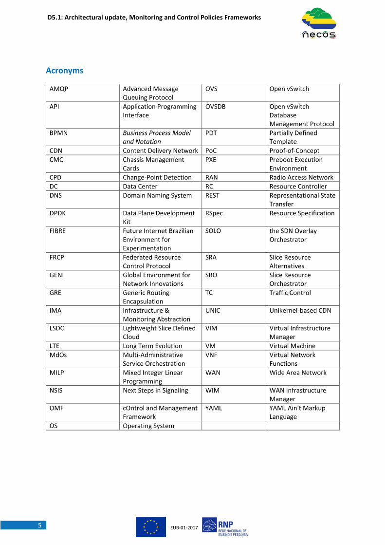
Acronyms
AMQP Advanced Message Queuing Protocol
OVS Open vSwitch
API Application Programming Interface
OVSDB Open vSwitch Database Management Protocol
BPMN Business Process Model and Notation
PDT Partially Defined Template
CDN Content Delivery Network PoC Proof‐of‐Concept
CMC Chassis Management Cards
PXE Preboot Execution Environment
CPD Change‐Point Detection RAN Radio Access Network
DC Data Center RC Resource Controller
DNS Domain Naming System REST Representational State Transfer
DPDK Data Plane Development Kit
RSpec Resource Specification
FIBRE Future Internet Brazilian Environment for Experimentation
SOLO the SDN Overlay Orchestrator
FRCP Federated Resource Control Protocol
SRA Slice Resource Alternatives
GENI Global Environment for Network Innovations
SRO Slice Resource Orchestrator
GRE Generic Routing Encapsulation
TC Traffic Control
IMA Infrastructure & Monitoring Abstraction
UNIC Unikernel‐based CDN
LSDC Lightweight Slice Defined Cloud
VIM Virtual Infrastructure Manager
LTE Long Term Evolution VM Virtual Machine
MdOs Multi‐Administrative Service Orchestration
VNF Virtual Network Functions
MILP Mixed Integer Linear Programming
WAN Wide Area Network
NSIS Next Steps in Signaling WIM WAN Infrastructure Manager
OMF cOntrol and Management Framework
YAML YAML Ain't Markup Language
OS Operating System

D5.1: Architectural update, Monitoring and Control Policies Frameworks
EUB‐01‐20176
ExecutiveSummaryNECOS project aims to define and implement a “Slice‐as‐a‐Service” architecture for multi‐domain
scenarios. The main idea is to exercise the concept of cloud network slicing as a complete solution for
provisioning end‐to‐end services among federated providers. This deliverable represents the initial
design of the architectural components defined in Deliverable D3.1 as well as their interactions in
terms of workflows that are necessary to perform the provisioning and maintenance of the slice. This
initial design is a step towards a more complete approach that will be presented in Deliverable D5.2
where detailed design of the components of the architecture will be shown. The workflows capture
the main steps and interactions that need to be followed to create a slice, to support elasticity and to
perform the decommission. This deliverable will also present a number of algorithms for realizing the
"Slice‐as‐a‐Service" concept as well as the provisioning mechanisms that can be adopted and/or
adapted from the current state‐of‐the‐art related projects.
D5.1: Architectural update, Monitoring and Control Policies Frameworks
EUB‐01‐20177
1. IntroductionWP5 is where the implementation of concepts and functions envisaged in other work packages has to
take place. As stated in the DoA, WP5 was initially conceived to deploy a monitoring an abstraction
layer (Task 5.1) and the intelligent orchestration functionality for the LSDC platform (Task 5.2). Each of
these tasks were also associated to the two deliverables of the project, which adopted names
associated to the above referred tasks. Therefore, D5.1 was initially conceived to report the design of
the monitoring framework and policies to be used in the context of the project showcases, and D5.2
to address the orchestration and other functionalities.
Nevertheless, at the early beginning of the project we realized two facts. The first fact was that starting
any task in WP5 without clear reference architecture, pursued in WP3, and was very difficult and prone
to make serious mistakes that would be hard to revert. The second fact was that WP5 should be aligned
with WP6 requirements because the main objective of WP6, also stated in the DoA, is to showcase the
ability of an integrated platform to serve both as a testbed of the integration of the prototyping results
and as a ground for demonstrating the NECOS use cases. The testing and demonstrations needed in
WP6 are then requiring the implementation of specific functionality in WP5, likely a subset of functions
of those specified in WP3. In summary, to effectively and efficiently start WP5 we had to wait until
WP3 and WP4 work reached a high mature level.
Despite the limitations exposed above, we decided to start WP5 activity at the early beginning of the
project to allow the development teams to get acquainted with already existing development tools
and development modules that could be used in subsequent stages. By doing this, we could anticipate
eventual challenges and make better decisions in the next steps.
The project has been shaping these initial developments in alignment with the evolution of the NECOS
architecture and its testing and demonstration requirements. As a result of this approach we are able
today to show the building blocks of what we call “proofs of concept” units; in other words, several
independent testing and demonstration modules. The platform development strategy planned up to
end of the project is based on two phases. The first phase, which has been reached at the end of the
project year one, is centered on the above‐mentioned building blocks. The second phase will be
reached at the end of the project and will consist of the same blocks with augmented functionality or
new ones if necessary.
1.1. DeliverableStructureThis document is organized to firstly show the design and implementation alternatives for a subset of
the architecture components defined in Deliverable D3.1. Then, detailed workflows are presented for
the main methods defined in Deliverable D4.1. These workflows are focused on depicting the
necessary behaviour of each component and try to conduct the reader to a step‐by‐step flow to
provide a view on the slice creation and elasticity process.
The rest of the document is organized as follows. In Section 2, based on Deliverable D3.1 overall
architecture and Deliverable D4.1 API specifications, it is possible to detail the architecture at the
function and implementation level. Thus, the section describes prototype internals, mapping the
interrelationship of components. In addition, it also presents a mapping of components to key enabler
technologies, for example, detailing the implementation in terms of programming languages and
D5.1: Architectural update, Monitoring and Control Policies Frameworks
EUB‐01‐20178
frameworks used like nodeJS, message processing using YAML formats, and reuse innovative
technologies to configure bare metal like PXE. In terms of network orchestration, we reuse some
testbed technologies from GENI, Fed4Fire and FIBRE. In summary, Section 2 details the candidate
implementations related to the core Slice Management and Lifecycle (Slice Builder, Broker and Agent)
as well as the candidate implementations for the DC Slice Controller and WAN Slice Controller.
Afterwards, in Section 3, using a well‐known design formalism, BPMN (Business Process Model and
Notation), this deliverable describes the workflows related to provisioning and orchestration of slices.
Several aspects are detailed, like the commission and decommission of slices and resources associated
to them. In addition, in order to achieve user‐defined policies and intelligent orchestration, this will
require automatic elasticity. Thus, this section details the interaction of the components that will allow
pursuing this.
Finally, in addition to the planned implementations described in Sections 2 and 3, in Section 4, we also
describe a set of algorithms and methods proposed within NECOS. We start from detailing a
"potpourri" of mechanisms outside or complementary to the main core components; from Blockchain
based Service Orchestration to Unikernel based CDNs as examples of NECOS enabled architecture. And
then, we describe a fundamental problem of slice embedding mechanisms, where optimization has to
be used to define from a set of resources which ones are the best to the slice allocation problem at
hand.
1.2. ContributionofthisDeliverabletotheprojectandrelationwithotherdeliverables
This deliverable is conceived to present the first implementation phase of NECOS and related
background needed to be achieved, whereas the subsequent deliverable, D5.2, will report the second
implementation phase. Therefore, the contributions listed in this deliverable are detailed
presentations of selected core components of the NECOS architecture, including internal functionality
and interactions, details of implementations as well as workflows of the components and functions
interactions. These core components were chosen based on D2.1 and D6.1, since they capture the
main use‐cases, KPIs and demonstrations that are being developed in the project.

D5.1: Architectural update, Monitoring and Control Policies Frameworks
EUB‐01‐20179
2. DetailedArchitectureDesignThe following subsections describe in more details the functional components of the NECOS
architecture, as was defined in Deliverable D3.1. In the descriptions that follow, we concentrate more
on the provisioning aspects and less on the elasticity aspects of the NECOS system, although the
elasticity flows are also presented later in the document. Thus, this section reports mainly on
components that are involved during the slice creation phase (eg, Slice Builder, Slice Agent, Broker,
etc.) but does not provide details regarding other components such as the Slice Resource Orchestrator
or the IMA. Although initial design ideas of these specific components are currently under
investigation, we consider these to be not in a mature state and likely to undergo major changes in the
future. However, the design of the components described in this section is mature enough for the
implementations of the first year proof‐of‐concepts.
Since NECOS is a research project and the architecture is expected to evolve based on the experiments
carried out in the next phases of the project, we describe the components following a prototype
approach, i.e., providing details of the prototype implementations developed so far. For some
components, there is more than one implementation approach. We expect that for the Deliverable
D5.2 a final design and implementation for each component of the architecture will be chosen and
adopted for the NECOS project.
In order to place the descriptions of the components in context, Figure 1 presents the NECOS functional
architecture. Full details regarding the functionality of the components are provided in Deliverable
D3.1.
Figure 1. NECOS functional architecture

D5.1: Architectural update, Monitoring and Control Policies Frameworks
EUB‐01‐201710
2.1. SliceBuilderThis section describes the Slice Builder and its internal functions, together with the Slice Specification
Processor, a component closely coupled with the Slice Builder. Figure 2 presents the main functions
of the Slice Builder and their interactions with internal and external entities. We describe these NECOS
entities along with examples of workflows inspired by our prototype implementation.
Figure 2. Slice Builder Internal Functions and Interactions
The Slice Specification Processor produces a template of the slice parts, namely the Partially Defined
Template (PDT). The PDT consists of DC slice parts, annotated with computing resource constraints,
and WAN slice parts that describe the desirable connections among providers. The PDT is derived from
the service description, originating from the Slice Activator (Interaction 1‐ Figure 2), and takes the
form of a YAML/JSON message, as it is described in Deliverable D4.1.
When the PDT message has been specified, the Slice Specification Processor sends such message to
the Slice Builder Engine (Interaction 2), which is the central Slice Builder function controlling all of its
processes.
The Slice Builder consists of the following functions, as depicted in Figure 2:
Slice Builder Engine: This is the main Builder function responsible for initiating the slice
resource discovery process, by forwarding the PDT to the Slice‐Part Resource Discovery
function (Interaction 3). The Builder Engine is responsible for processing the Slice Resource
Alternatives (SRA) message received via the Slice‐Part Resource‐Discovery from the Slice
Broker (Interaction 5), and selecting slice resources that best fit the Tenant’s requirements. In
order to perform this task, the Builder Engine formulates the selection process as an
optimization problem, to find the optimal resource instantiation. Upon deciding on a resource
instantiation, the Engine forwards the instantiation description to the Slice‐Part‐Activator
(Interaction 6‐Figure 2). Finally, when the Slice Discovery and Instantiation phases are
complete, it returns the complete slice details to the Slice Resource Orchestrator (Interaction
9).
Slice‐Part Resource Discovery: This function is responsible for sending the PDT and receiving
the SRA message (Interaction 4). It is an implementation of the message interface between
the Slice Builder as a whole and the Slice Broker. Its role is to check the integrity of the PDT
D5.1: Architectural update, Monitoring and Control Policies Frameworks
EUB‐01‐201711
message and the SRA message received. The reply (SRA) is then forwarded to the Slice Builder
Engine (Interaction 5).
Slice‐Part Activator: The role of this function is to receive (Interaction 6) an almost complete
slice parts’ description and contact each DC and WAN providers to instantiate the resources.
The Activator contacts each provider’s WAN‐ or DC‐ Slice Controller (Interaction 7) and upon
successful resource instantiation, it receives back details regarding on accessing each
particular resource (e.g., IP addresses of allocated physical servers to the slice). When all slice
parts have been instantiated, it sends back to the Builder Engine the complete information
(Interaction 8).
In our prototype implementation, the Slice Specification Processor and the Slice Builder internal
functions are based on the Node‐RED, YAML, JSON and NodeJS/JavaScript. In practice, all these entities
process information in the form of YAML, communicate it in the form of JSON and all of their algorithms
are implemented as NodeJS/JavaScript modules. The Slice Specification Processor and the Slice
Builder functions are independent Node‐RED nodes, allowing their extensible operation and the
visualization of the involved workflows. Our current steps include integrating optimization tools and
libraries in the Slice Builder Engine for solving the optimization problem, as described above.
2.2. SliceBrokerThis section describes the Slice Broker (depicted in Figure 3), in line with its internal functions and
interactions that arise in its communication with the Slice Builder and the Slice Agents. As before, the
workflows, depicted in Figure 3, are inspired from our prototype implementation and used to highlight
the design aspects of this particular NECOS entity, i.e., the Slice Broker.

D5.1: Architectural update, Monitoring and Control Policies Frameworks
EUB‐01‐201712
Figure 3. Internal functions and Interactions
In practice, three main functions compose the Slice Broker, namely the PDT Message Analyser, the
Resource Discovery Control and the Provider and Resource DB, all of them depicted in Figure 3. In
more details, each function has the following responsibilities:
The PDT Message Analyser is responsible for receiving the PDT template (Interaction 1)
originated in the Slice Specification Processor and passing through the Slice Builder to end up
in the Slice Broker. Once the Analyser receives the template describing the slice to be
deployed, it proceeds with its decomposition to different queries/requests, one for each slice
component, either dc‐slice‐part or net‐slice part (according to the Deliverable D4.1). The
output of this process is directed to the Resource Discovery Control (Interaction 2) to initiate
the actual discovery process.
The Resource Discovery Control function reflects the implementation of the message
interface between the Slice Broker as a whole and the Slice Agent. It exposes on behalf of the
Broker the register_provider and the push_resource_offer APIs, while it also responds to the
pull_resource_offer API exposed by the Slice Agent (these APIs compose the Interaction 4).
D5.1: Architectural update, Monitoring and Control Policies Frameworks
EUB‐01‐201713
The main responsibility of this component is to “get out” to the Marketplace and “look for”
the slice‐parts (DC or WAN) required according to the input received by the PDT Message
Analyser. Typically, once this entity gets informed of the available providers, it can update its
knowledge of resource offers, their geographic details and accompanied cost either in a push
or a pull mode. All information collected from these APIs will be registered in the Provider and
Resource DB (Interaction 3). Then, according to the incoming slice request message
(Interaction 1) and the offers gathered, this function proceeds to the corresponding response
in the form of an SRA message (Interaction 5).
The Provider and Resource DB function is responsible for recording all the incoming ‐ from the
Marketplace ‐ information and/or offers through the Resource Discovery Control (Interaction
3). It maintains a database with information on the providers IDs, their geographic location,
the resource elements they offer as well as their cost (this list in not exhaustive).
In our prototype, the Slice Broker is implemented as a Node‐RED node and exchanges information
with the other NECOS components based on the YAML/JSON technologies. Main algorithms of the
Slice Broker are based on NodeJS/JavaScript, such us the message processing of the PDT message
analyser. However, the Resource Discovery Control internal Broker function is being implemented as
a dedicated Java software, which offers alternative ways to communicate information in the context
of the resource discovery (e.g., through Publish/Subscribe or Push/Pull). Such communication method
is being decided dynamically, according to the conditions of the resource discovery and the slice
requirements (i.e., tunes the involved performance trade‐offs, accordingly). The Provider and
Resource DB function is implemented as a NodeJS/JavaScript wrapper to the Redis database
technology.
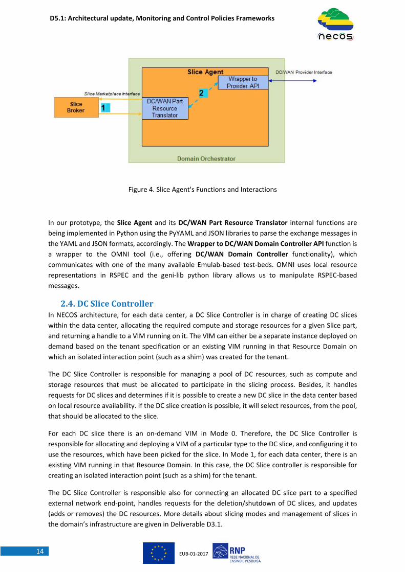
2.3. SliceAgentThe Slice Agent is a part of the NECOS Marketplace (i.e., initially defined in Deliverable D3.1) that
resides on the provider’s domain. The role of the Slice Agent is to answer requests for resources that
originate from the Slice Broker for a specific DC‐ or WAN‐slice part. This message is translated in a
form that the corresponding DC or WAN provider can process (i.e., to lookup the requested resources
through its own provider‐specific resource directory ‐ a task carried out from the particular DC/WAN
Domain Controller) and the answer received from the controller is passed to the Slice Broker. The
Slice Agent consists of the DC/WAN Part Resource Translator and the Wrapper to DC/WAN Domain
Controller API internal functions (Figure 4). The Resource Translator parses the YAML/JSON message
received by the Slice Broker and transforms it to a DC‐ or WAN‐technology dependent form. The
Wrapper to DC/WAN Domain Controller API function communicates through the DC/WAN Domain
Controller Interface with the local DC/WAN Domain Controller handling a local resource directory.
The latter matches the requested resources with those available in the particular provider and creates
the response. This is not yet in a form to become one of the offers described in the Slice Resource
Alternatives (SRA) message, because it requires a provider‐agnostic representation. Such process is
being handled from the DC/WAN Part Resource Translator function, which converts the response to
the relevant form defined in the NECOS information model (i.e., see Deliverable D4.1).
D5.1: Architectural update, Monitoring and Control Policies Frameworks
EUB‐01‐201714
Figure 4. Slice Agent's Functions and Interactions
In our prototype, the Slice Agent and its DC/WAN Part Resource Translator internal functions are
being implemented in Python using the PyYAML and JSON libraries to parse the exchange messages in
the YAML and JSON formats, accordingly. The Wrapper to DC/WAN Domain Controller API function is
a wrapper to the OMNI tool (i.e., offering DC/WAN Domain Controller functionality), which
communicates with one of the many available Emulab‐based test‐beds. OMNI uses local resource
representations in RSPEC and the geni‐lib python library allows us to manipulate RSPEC‐based
messages.
2.4. DCSliceControllerIn NECOS architecture, for each data center, a DC Slice Controller is in charge of creating DC slices
within the data center, allocating the required compute and storage resources for a given Slice part,
and returning a handle to a VIM running on it. The VIM can either be a separate instance deployed on
demand based on the tenant specification or an existing VIM running in that Resource Domain on
which an isolated interaction point (such as a shim) was created for the tenant.
The DC Slice Controller is responsible for managing a pool of DC resources, such as compute and
storage resources that must be allocated to participate in the slicing process. Besides, it handles
requests for DC slices and determines if it is possible to create a new DC slice in the data center based
on local resource availability. If the DC slice creation is possible, it will select resources, from the pool,
that should be allocated to the slice.
For each DC slice there is an on‐demand VIM in Mode 0. Therefore, the DC Slice Controller is
responsible for allocating and deploying a VIM of a particular type to the DC slice, and configuring it to
use the resources, which have been picked for the slice. In Mode 1, for each data center, there is an
existing VIM running in that Resource Domain. In this case, the DC Slice controller is responsible for
creating an isolated interaction point (such as a shim) for the tenant.
The DC Slice Controller is responsible also for connecting an allocated DC slice part to a specified
external network end‐point, handles requests for the deletion/shutdown of DC slices, and updates
(adds or removes) the DC resources. More details about slicing modes and management of slices in
the domain’s infrastructure are given in Deliverable D3.1.

D5.1: Architectural update, Monitoring and Control Policies Frameworks
EUB‐01‐201715
The Slice Instantiation Interface and the Slice Runtime Interface are both used to communicate with
the DC Slice Controller, as is shown in Figure 5. In the following, we describe two candidate
implementations of the DC Slice Controller that are being exercised in NECOS. Both implementations
currently are focused on the Mode 0 approach, where VIMs are deployed on demand.
Candidate Implementation 1
Figure 5 shows the first option for implementing the DC Slice Controller, its internal functions and basic
interactions. After the end of the resource discovery phase, the Slice Builder communicates with all
the providers offering DC slice parts in order to start the slice deployment.
Figure 5. DC Slice Controller’s Functions and Interactions (Candidate implementation 1)
The other end of the communication is being handled by DC Slice Controllers, deployed in each DC
provider (Interaction 1). This process includes a translation of the communicated slice part request
through the DC‐Resource Translator API to specific commands that actually allocate the specific slice
part through the DC‐Activator (Interaction 2). Such process includes the booting up of server resources
based on particular server images, the configuration of the local network (e.g., deployment of VLANs)
and the creation of the user accounts. These steps are being defined in a provider technology
independent form, i.e., according the NECOS information model, but should be translated to the
particular provider’s technology (Interaction 3). This activity is handled from the Wrapper to DC
Domain Controller API function, which communicates with the particular DC Domain Controller
through the DC Domain Controller Interface. During the slice runtime operation, the Slice Resource
Orchestrator may implement elasticity capabilities, e.g., slicing up or down of the resources through
communicating with the DC‐Activator (Interaction 4).
In our prototype implementations, the DC Slice Controller is implemented with the same technologies
with the Slice Agent (i.e., Python implementation based on the PyYAML, JSON, geni‐lib libraries). It
also involves the OMNI tool, which is the equivalent of a DC Domain Controller. The OMNI tool
processes RSPEC request messages defining the complete process to deploy a slice part, e.g., booting
up of servers, installing a server image, setting up the network, creating user accounts, etc. Such RSPEC
message is being created through the geni‐lib library based on the initial slice‐part request coming
from the Slice Builder.
D5.1: Architectural update, Monitoring and Control Policies Frameworks
EUB‐01‐201716
Candidate Implementation 2
Figure 10 illustrates another implementation of the DC Slice Controller, which has been exercised in
NECOS. This implementation takes as starting point elements from the Control and Management
Framework (OMF) [SC1] (version 6.0), one of the prevalent tool for experimentation in networking
testbeds providing heterogeneous resources. Particularly, we reuse part of the OMF communication
interface, specifically the Federated Resource Control Protocol ‐ FRCP. FRCP is a protocol that allows
to communicate with Resource Controllers (RCs) in order to query or configure the state of the
underlying resources. We also reuse the OMF's brokerage layer and some testbed services provided
by the framework, such as the Chassis Management Cards (CMC) and the service responsible for
provisioning disk images on compute resources. The brokerage layer is a message‐oriented
middleware layer (e.g. Advanced Message Queuing Protocol ‐ AMQP) that integrates the management
framework with resources and services of the testbed. The CMC is a testbed service responsible for
powering on/off the compute resources remotely, thus without human intervention. Booting over the
network is achieved using the Intel specification called Preboot Execution Environment (PXE).
D5.1: Architectural update, Monitoring and Control Policies Frameworks
EUB‐01‐201717
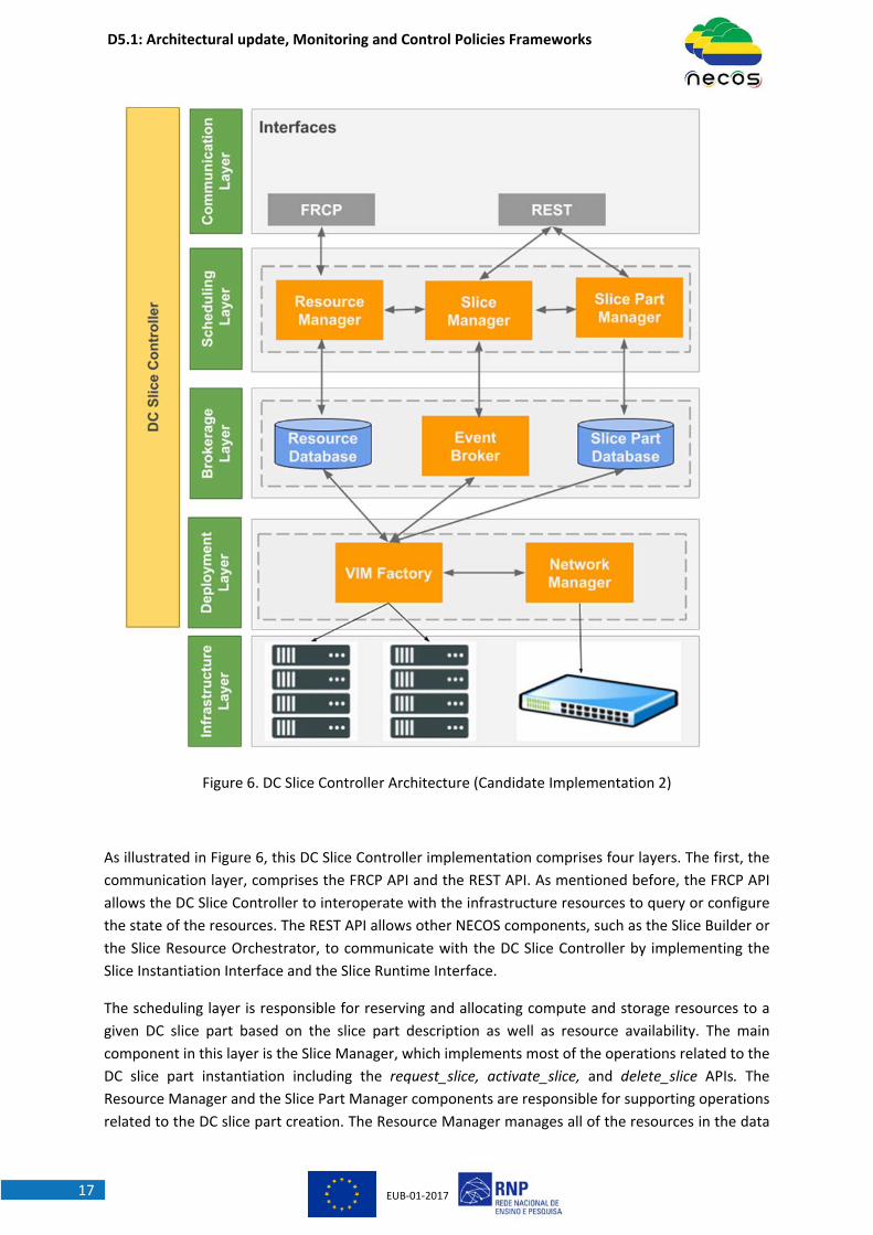
Figure 6. DC Slice Controller Architecture (Candidate Implementation 2)
As illustrated in Figure 6, this DC Slice Controller implementation comprises four layers. The first, the
communication layer, comprises the FRCP API and the REST API. As mentioned before, the FRCP API
allows the DC Slice Controller to interoperate with the infrastructure resources to query or configure
the state of the resources. The REST API allows other NECOS components, such as the Slice Builder or
the Slice Resource Orchestrator, to communicate with the DC Slice Controller by implementing the
Slice Instantiation Interface and the Slice Runtime Interface.
The scheduling layer is responsible for reserving and allocating compute and storage resources to a
given DC slice part based on the slice part description as well as resource availability. The main
component in this layer is the Slice Manager, which implements most of the operations related to the
DC slice part instantiation including the request_slice, activate_slice, and delete_slice APIs. The
Resource Manager and the Slice Part Manager components are responsible for supporting operations
related to the DC slice part creation. The Resource Manager manages all of the resources in the data

D5.1: Architectural update, Monitoring and Control Policies Frameworks
EUB‐01‐201718
center and keeps the resources and their states up to date, thus implementing the resource
management function of the DC Slice Controller. The Slice Part Manager keeps track of which compute
and storage resources have been allocated to which DC slice part and responds to queries related to
the DC slice part elements, such as those of the get_slice_part_elements API and the
get_element_handle API defined in the Slice Runtime Interface.
The brokerage layer integrates scheduling operations to concrete deployment actions that will be
taken over the infrastructure. This integration is realized by events triggered by the Slice Manager to
the Event Broker, as well as the Resource and Slice Part Databases. One example of event triggered by
the Slice Manager is the one that starts the activation of the slice according to the start time attribute
of the allocation. The Resource Database stores data related to the main objects that are supported
by the NECOS infrastructure information model (as depicted in Deliverable D4.1) while the Slice Part
Database keeps information related to the slice parts in the DC provider.
Finally, the deployment layer implements the services that actually instantiate the DC slice part. The
main component in this layer is the VIM Factory, which is in charge of deploying the VIM of a particular
type to the DC slice part and configure it to use the resources, which have been picked for the slice. To
deploy the VIM, the VIM Factory uses the CMC service to boot the compute resources remotely. The
system initialized through this service is reduced, having only the root account, some basic tools and
the Resource Controller that allows a complete image of an operating system (and the chosen VIM) to
be brought from a repository to be applied to the hard disk of the compute resources. The Network
Manager is responsible for creating an isolated network for the DC slice part inside the DC domain and
connects this network to a specified external network end‐point provided by the WAN Slice Controller.
The workflow inside the DC Slice Controller for creating a DC slice part is described in the following.
First, the Slice Manager receives, through the REST API, a request_slice API call. It then interacts with
the Resource Manager and the Slice Part Manager to determine if it is possible to create a new slice
part in the domain. If the slice part creation is possible, the Slice Manager selects the resources that
satisfy the request, registers the new slice part (and resources) in the Slice Part Database and schedules
the slice part activation. This scheduling is done by contacting the Event Broker. As soon as the
scheduled event is triggered, the VIM Factory is called to deploy the VIM image on the allocated
compute resources. The VIM Factory then contacts the Network Manager to set up the slice part
network. After the DC slice part being instantiated and configured the VIM entry point is returned to
the caller.
Currently, this implementation of the DC Slice Controller uses the following technologies. Most of the
components are implemented in Ruby version 2.3.1. We use SQLite 3.25 for the databases (Resource
and Slice Part), AMQP 1.0 for the Event Broker, OpenFlow 1.0 and Open vSwitch (OVS) 2.6.2 for the
Network Manager, and Frisbee as the disk image management tool. Except by the FRCP (and Resource
Controllers), the brokerage layer, the CMC service, and the disk image service, which are reused from
OMF, the other components were implemented in the NECOS project.
D5.1: Architectural update, Monitoring and Control Policies Frameworks
EUB‐01‐201719
2.5. WANSliceControllerThe WAN Slice Controller is the component that resides inside each Network Provider and that
dynamically creates a Network slice, as a part of a full cloud network slice. A Network slice is a set of
virtual links that connects two DC slices. In order to create a Network slice, the WAN Slice Controller
manages all of the network resources in the network provider domain that are allocated to participate
in slicing and keeps track of which network resources have already been allocated to which slice.
The WAN Slice Controller handles requests for Network slices and determines if it is possible to create
a new network slice in the network domain based on local resource availability (e.g. bandwidth). If the
Network slice creation is possible, the WAN Slice Controller provides the set of virtual links required to
connect the given DC slice parts.
In mode 0, for each Network slice there is an on‐demand WIM allocation. In this case, the WAN Slice
Controller deploys a WIM to the Network slice and configures it to use the network resources, which
have been assigned for the slice. In mode 1, for each network domain, there is an existing common
WIM running in that domain that is shared by multiple slices. Thus, the WAN Slice controller is
responsible for creating an isolated interaction point (such as a shim) for each tenant.
The WAN Slice Controller allows to handle requests for the deletion/shutdown of WAN slices and
updates the network resources assigned to the slice on‐the‐fly as a slice can grow or shrink at runtime.
More details about WAN Slice Controller operations are given in Deliverable D3.1. In the following, we
describe two alternative implementations of the WAN Slice Controller that are being exercised in
NECOS.
Candidate Implementation 1
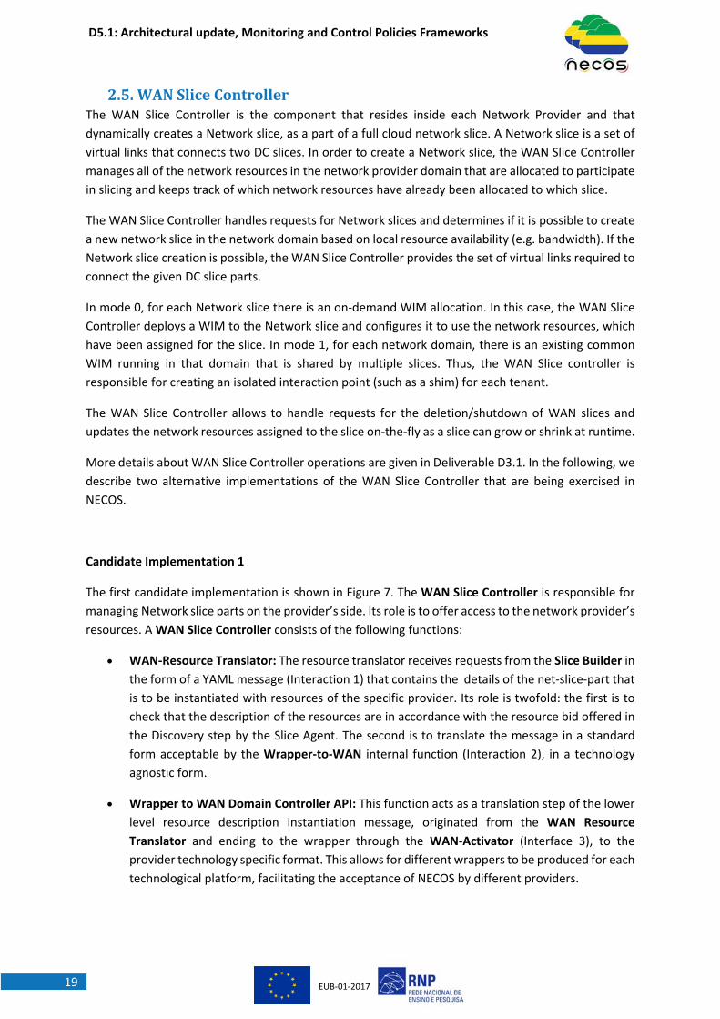
The first candidate implementation is shown in Figure 7. The WAN Slice Controller is responsible for
managing Network slice parts on the provider’s side. Its role is to offer access to the network provider’s
resources. A WAN Slice Controller consists of the following functions:
WAN‐Resource Translator: The resource translator receives requests from the Slice Builder in
the form of a YAML message (Interaction 1) that contains the details of the net‐slice‐part that
is to be instantiated with resources of the specific provider. Its role is twofold: the first is to
check that the description of the resources are in accordance with the resource bid offered in
the Discovery step by the Slice Agent. The second is to translate the message in a standard
form acceptable by the Wrapper‐to‐WAN internal function (Interaction 2), in a technology
agnostic form.
Wrapper to WAN Domain Controller API: This function acts as a translation step of the lower
level resource description instantiation message, originated from the WAN Resource
Translator and ending to the wrapper through the WAN‐Activator (Interface 3), to the
provider technology specific format. This allows for different wrappers to be produced for each
technological platform, facilitating the acceptance of NECOS by different providers.
D5.1: Architectural update, Monitoring and Control Policies Frameworks
EUB‐01‐201720
WAN‐Activator: The WAN‐Activator is responsible to receive requests from the Slice Resource
Orchestrator (Interaction 4), in order to “connect” different services running on the DC‐Slice‐
parts it connects.
Figure 7. WAN Slice Controller’s Functions and Interactions (Candidate Implementation 1)
In this specific prototype implementation, we use a similar approach for the WAN Slice Controller with
the DC/WAN Slice Agents, i.e., Python implementation based on the PyYAML, JSON libraries, and
realize a Provider API through the OMNI tool. OMNI is also able to control the test‐bed resources
through RSPEC messages. For example, we connect the different providers using the alternative link
stitching options provided by the FED4FIRE test‐bed facilities. In our case, we mostly implement GRE
tunnelling and emulate the allocation of the requested bandwidth resources using the TC linux tool. In
a real deployment, resource reservation protocols can be employed for this task (e.g, NSIS).
Candidate Implementation 2
Since the WAN Slice Controller is the counterpart of the DC Slice Controller in the Network provider, it
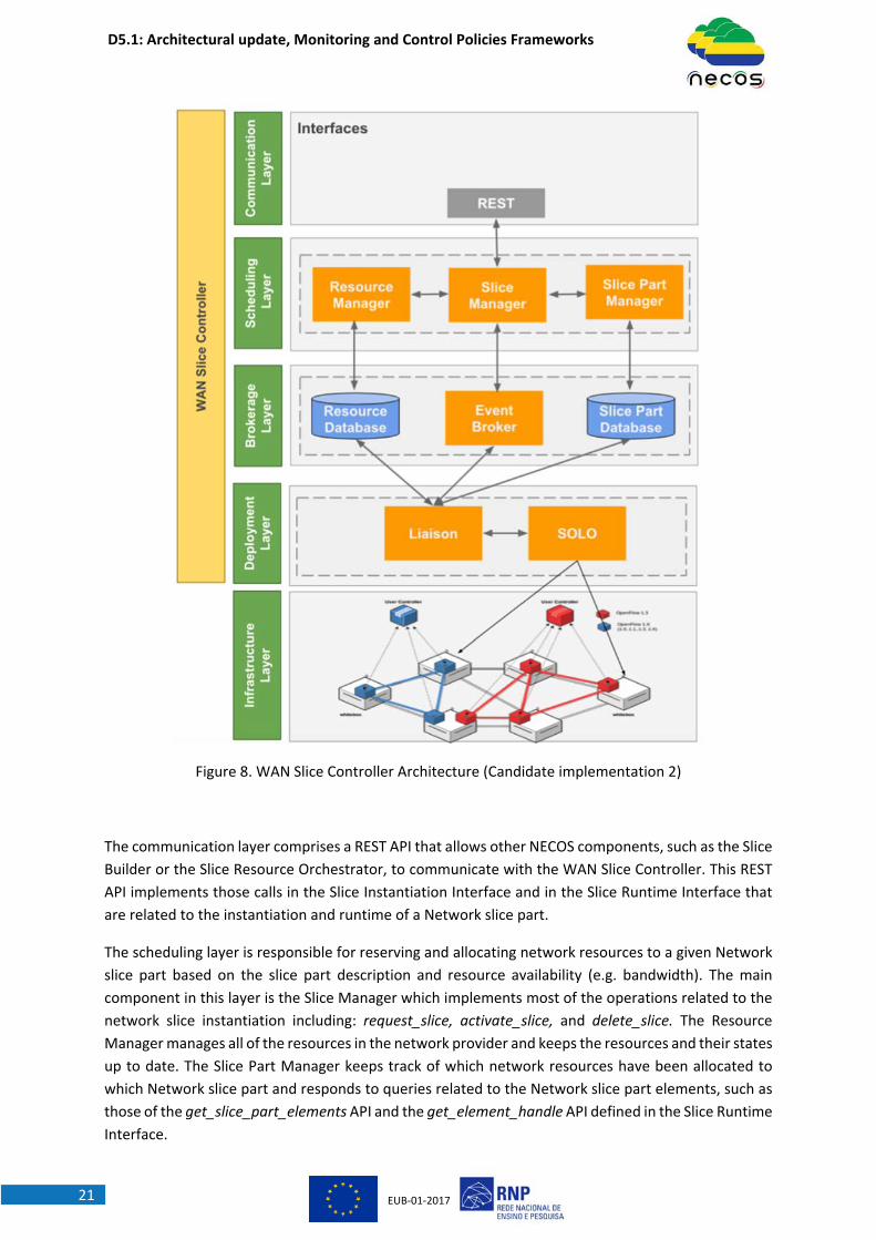
is natural that both implementations share common design options. As shown in Figure 8,
implementation 2 of the WAN Slice Controller is based on similar layers presented in implementation
2 of the DC Slice Controller. The main difference between these two implementations lies in the
deployment layer. In the WAN Slice Controller, most of the operations related to the actual
instantiation of a given Network slice part is carried out by the SDN Overlay Orchestrator (SOLO) [SC2],
a solution developed by RNP for slicing network resources in WAN domains. In the following, we
describe each layer in more detail.
D5.1: Architectural update, Monitoring and Control Policies Frameworks
EUB‐01‐201721
Figure 8. WAN Slice Controller Architecture (Candidate implementation 2)
The communication layer comprises a REST API that allows other NECOS components, such as the Slice
Builder or the Slice Resource Orchestrator, to communicate with the WAN Slice Controller. This REST
API implements those calls in the Slice Instantiation Interface and in the Slice Runtime Interface that
are related to the instantiation and runtime of a Network slice part.
The scheduling layer is responsible for reserving and allocating network resources to a given Network
slice part based on the slice part description and resource availability (e.g. bandwidth). The main
component in this layer is the Slice Manager which implements most of the operations related to the
network slice instantiation including: request_slice, activate_slice, and delete_slice. The Resource
Manager manages all of the resources in the network provider and keeps the resources and their states
up to date. The Slice Part Manager keeps track of which network resources have been allocated to
which Network slice part and responds to queries related to the Network slice part elements, such as
those of the get_slice_part_elements API and the get_element_handle API defined in the Slice Runtime
Interface.
D5.1: Architectural update, Monitoring and Control Policies Frameworks
EUB‐01‐201722
The brokerage layer integrates scheduling operations to concrete slicing actions that will be taken over
the network infrastructure. This integration is realized by events triggered by the Slice Manager to the
Event Broker, as well as the Resource and Slice Part Databases. The Resource Database stores data
related to the main objects that are supported by the NECOS infrastructure information model, while
the Slice Part Database keeps information related to the slice parts in the Network provider.
The deployment layer implements the services related to the actual instantiation of the network slice
part. The main component in this layer is SOLO, which is in charge of slicing the network resources and
deploying a on demand WIN to manage the network slice part. SOLO implements a network
virtualization model and tunnelling, which enables the creation of network substrates that are
programmed separately and transparently by independent SDN controllers. These controllers can be
created dynamically fitting the WIM on demand approach proposed in NECOS. In addition, SOLO can
provide virtual links with QoS guarantees. Currently, SOLO provides a REST API that allows for the
creation (and removal) of virtual switches, virtual ports, and virtual links. In this implementation of the
WAN Slice Controller, this API is invoked for creating a network slice part that connects two DC slice
parts. The Liaison is the WAN Slice Controller component in charge of mapping the NECOS request into
a request that can be processed by SOLO.
The workflow inside the WAN Slice Controller is as follows. First, the Slice Manager receives, through
the REST API, a request_slice call. It then interacts with the Resource Manager and the Slice Part
Manager to determine if it is possible to create a new network slice part in the domain. If the slice part
creation is possible, the Slice Manager selects the resources that satisfy the request, registers the new
slice part (and resources) in the Slice Part Database and schedules the network slice part activation
according to the start time attribute of the slice. This scheduling is done by contacting the Event Broker.
When the scheduled event is triggered, the Liaison is called to map the network slice part request into
requests that will be send to SOLO. As soon as the network slice is created and the WIM is instantiated,
the WIM handle is returned to the caller.
Currently, this implementation of the WAN Slice Controller uses the same technologies as those
described in corresponding layers in implementation 2 of the DC Slice Controller. The Liaison
Component is implemented in Ruby (version 2.3.1), while SOLO is implemented in Java using
virtualization technologies such as Open vSwitch, DPDK, OVSDB, and OpenFlow.
D5.1: Architectural update, Monitoring and Control Policies Frameworks
EUB‐01‐201723
3. ProvisioningandOrchestrationWorkflowIn this section, we use BPMN (Business Process Model and Notation) methodology to document the
current flows developed in NECOS. The diagrams in this section are still work in progress and,
therefore, the final version will be included in Deliverable D5.2.
The workflows currently available include Slice Creation (Section 3.1), Slice Decommission (Section
3.2), Slice Elasticity with Upgrade of Slice Resources (Section 3.3) and Slice Elasticity with Downgrade
of Slice Resources (Section 3.4).
Regarding the notation adopted for building the diagrams, a green circle denotes the start of a
workflow and an orange circle denotes the end of a workflow. A rounded gray rectangle represents an
action taken during the workflow. A set of actions (gray rectangles) is grouped in dashed squared boxes
to represent a NECOS Architectural component, i.e., they represent a set of actions assigned to a
specific module proposed in NECOS architecture.
There are different types of gateways (diamond shapes) in the workflows. The diamond with a circle
inside represents an Inclusive gateway, i.e., when the flow reaches such a gateway, it is necessary to
evaluate the set of next steps to be taken. It is possible to select a mix of actions composed by one or
more steps linked from this gateway. The diamond with an X inside represents an Exclusive gateway,
i.e., when the flow reaches such a gateway, only one next step is taken from the options linked in this
gateway. The diamond with an + inside represents a Parallel gateway, i.e., when the flow reaches such
a gateway, all the steps linked from this gateway are performed in parallel.
3.1. SliceCreationWorkflowThis section documents the slice creation workflow according to architectural design aspects available
on Deliverable D3.1 and APIs defined on Deliverable D4.1. Figure 9 shows all the architectural modules
involved in the Slice Creation workflow, and the arrows represent the interaction in between modules
required to create a new slice. For this workflow we assume that a tenant seating at the Service
Provider realm uses the Slice Activator module to issue a slice request to a NECOS Slice Provider. The
Slice Provider interacts with the Marketplace and Infrastructure Providers in order to deliver the slice
to the tenant. The process finishes with the Slice Activator delivering all the details of the new slice to
the Service Orchestrator module. This later will start the Service Deployment Workflow on top of this
new slice by communicating with the Service Orchestrator Adaptor using the dotted line present in
Figure 9. The Service Deployment is left for future versions of this deliverable.

D5.1: Architectural update, Monitoring and Control Policies Frameworks
EUB‐01‐201724
Figure 9. Overall slice creation workflow
Figure 9 depicts the architectural modules involved in the slice creation workflow, a total of eleven
modules (except the Service Orchestrator Adaptor) located in four different realms (Service Provider,
Slice Provider, Infrastructure Provider and Marketplace). The Infrastructure Provider realm has a
component named Domain Orchestrator, which is a native component present in the Infrastructure
Providers that receive two modules from NECOS, the Slice Agent and the DC/WAN Slice Controller. The
interactions in between modules are represented using uni‐ and bi‐directional arrows; the arrows can
represent more than one interaction in between a given pair of modules. The detailed interactions will
be depicted in the next figures on this section that present all actions taken by a module in the overall
workflow. Interactions in between realms are identified by interfaces numbered as I1 to I6, defined in
Deliverable D4.1. The interface I6 is part of the Service Deployment workflow; it is represented in
Figure 9 to give an overview on how we plan to proceed after obtaining a new slice.
Figure 10 details the Slice Activator, the module in which the Slice Creation workflow starts with the
tenant performing a login in a NECOS frontend, which authenticates the tenant and allows him/her to
issue a new slice request. In the sequence, the workflow considers that the tenant will have access to
a catalog in order to specify his/her new slice. As defined in Deliverable D3.1, there are different
abstraction levels to specify a slice; the catalog will offer the possibility to do so in all the proposed
abstraction levels.
From the catalog, the workflow arrives at an inclusive gateway, which provides support to the
composition of slices considering all possible mixes in between specification by Service KPIs (highest
abstraction allowed) and Resources (lowest abstraction allowed). As a result of this phase, the
workflow reaches the point in which the Slice Activator has a Slice Description, composed by a mix of
Service KPIs and Resources.

D5.1: Architectural update, Monitoring and Control Policies Frameworks
EUB‐01‐201725
The Slice Description is sent to the Slice Specification Processor module, which is located at the Slice
Provider realm, through the Client‐to‐Cloud API defined in Deliverable D4.1. Figure 10 refers to such
API using the blue circle identified as I1.
As defined in Deliverable D4.1, the Client‐to‐Cloud API includes three flavours of a method named
create_slice(), the different flavours exist in order to support the different abstraction levels and also
the request of slices that will be activated in a given moment in the future.
The Slice Specification Processor translates to resources (lower abstraction allowed) the service KPIs
contained in the slice description from the Slice Activator and forwards it to the Slice Builder module.
Figure 11 presents the details of the Slice builder, in which an alternative flow (Exclusive gateway)
forwards to the Slice Activator the responsibility of selecting the Final Slice Configuration. This is useful
for cases in which the tenant is asked to pick one among many possible slice arrangements.
After the definition of the Final Slice Configuration, the workflow moves towards the preparation of
the Slice Contract, which is established in between tenant (Service Provider), Slice Provider and all
Infrastructure Providers. The Slice Activator, while handling the contract, can make the option to sign
it, or reject the contract. In such later case, the slice creation workflow would be finished and the slice
will not be created. This is a clear example of a step that can be further elaborated, allowing the
rollback of steps, like returning to the selection of the Final Slice Configuration. Such improvements
will be detailed in Deliverable D5.2, after the deployment and experimentation of such workflows in
our testbeds.
Figure 10. Detailed Slice Activator participation in the Slice Creation Workflow
Assuming the case in which the contract is signed, the workflow moves towards the moment in which
the Slice Resource Orchestrator, detailed in Figure 15, concludes the slice creation and returns the
pointers to the Slice Activator, characterizing that the new Slice is Active. Finally, Figure 10 also depicts
a task regarding the Triggering of Service Deployment in which, as mentioned before, the Service
Deployment starts.

D5.1: Architectural update, Monitoring and Control Policies Frameworks
EUB‐01‐201726
Figure 11 depicts the actions taken by the Slice Builder, starting from the validation of the Slice Request
delivered to it by the Slice Specification Processor. The validation, for example, as exemplified in our
project proposal, includes research regarding policies and rules. Once the request is validated, the Slice
Builder generates the PDT (Partially Defined Template) message, which is used to communicate with
the Slice Broker in the Marketplace through the Cloud‐to‐Cloud interface I2 of Figure 11. As defined in
Deliverable D4.1, the communication in between the Slice Builder and the Slice Broker receives the
denomination of Slice Request Interface, and currently has a method named locate_slice_resources().
The Slice Broker will return using a SRA (Slice Resource Alternatives) message. There is a dotted line in
Figure 11 suggesting a loop of PDT/SRA messages. This is due to the fact that perhaps all cloud/edge
resources are selected first, allowing the best selection of network resources given the actual
placement of the other types of resources.
As mentioned during the Slice Activator description, the Slice Builder uses an exclusive gateway to
select the Final Slice Configuration. Such an option brings investigation alternatives to the project,
allowing the research on reasoning modules that could decide by themselves at the Slice Builder, or
solutions that involve the tenant selecting one among the alternatives at the level of the Slice Activator
module. Independent of the adopted solution, once the final slice configuration is defined, the contract
is generated and through a parallel gateway is forwarded to all involved actors for collecting the
signatures. This mechanism is being investigated in the project by considering blockchain as a possible
enabling technology.
Figure 11. Detailed Slice Builder participation in the Slice Creation Workflow
To conclude, the Slice Builder requests to all Infrastructure Providers, via their respective DC/WAN
Slice Controllers, the deployment of the slice parts at their responsibility, delivering the full slice details
to the Slice Resource Orchestrator (Figure 15). The communication in between the Slice Builder and
the DC/WAN Slice Controllers occurs via the Slice Request Instantiation Interface specified in
Deliverable D4.1 and depicted in Figure 11 as I4. This interface exposes a method named
request_slice().
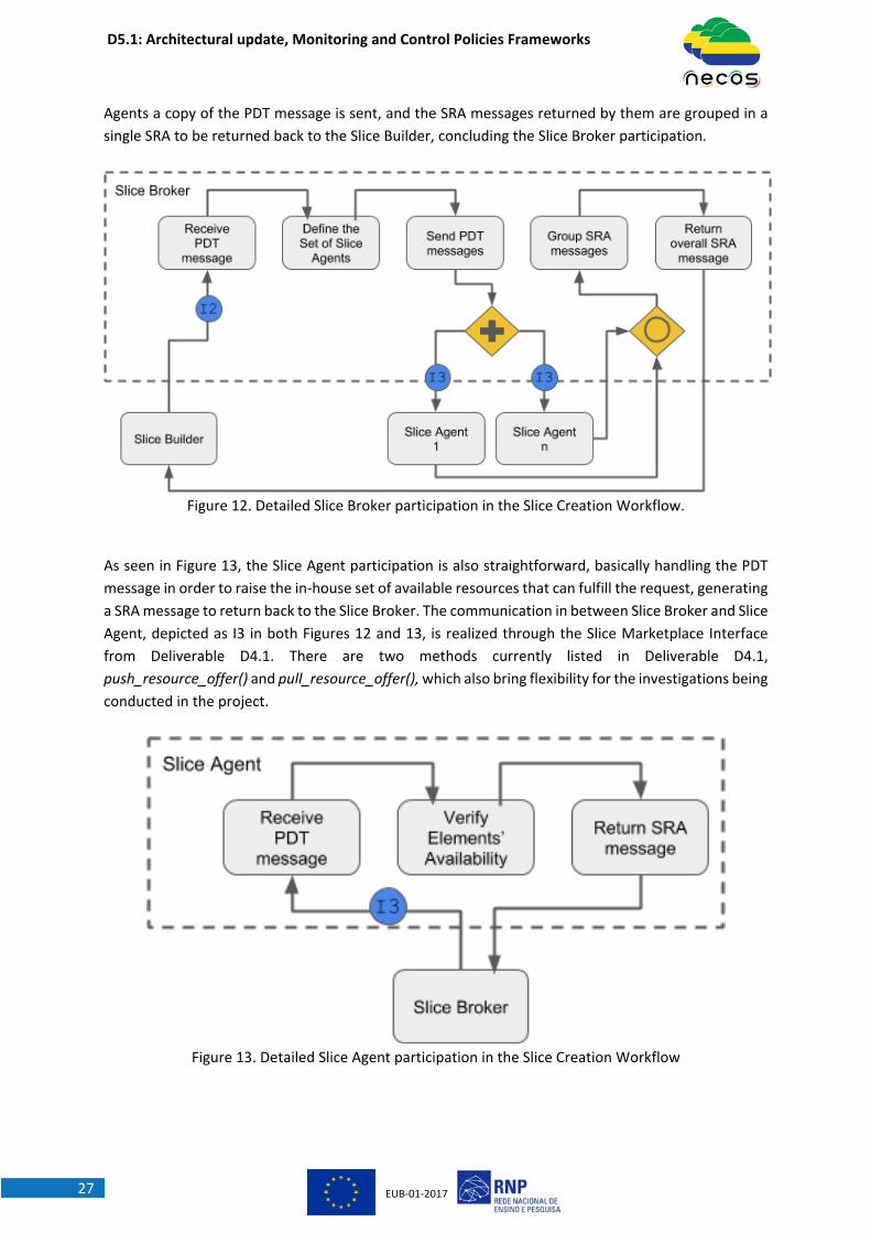
Figure 12 depicts the Slice Broker involvement in the Slice Creation workflow, starting from the
locate_slice_resources() request from the Slice Builder, in which a PDT message is sent to the Slice
Broker. The PDT is evaluated and a set of possible Slice Agents is defined. To each one of the Slice
D5.1: Architectural update, Monitoring and Control Policies Frameworks
EUB‐01‐201727
Agents a copy of the PDT message is sent, and the SRA messages returned by them are grouped in a
single SRA to be returned back to the Slice Builder, concluding the Slice Broker participation.
Figure 12. Detailed Slice Broker participation in the Slice Creation Workflow.
As seen in Figure 13, the Slice Agent participation is also straightforward, basically handling the PDT
message in order to raise the in‐house set of available resources that can fulfill the request, generating
a SRA message to return back to the Slice Broker. The communication in between Slice Broker and Slice
Agent, depicted as I3 in both Figures 12 and 13, is realized through the Slice Marketplace Interface
from Deliverable D4.1. There are two methods currently listed in Deliverable D4.1,
push_resource_offer() and pull_resource_offer(), which also bring flexibility for the investigations being
conducted in the project.
Figure 13. Detailed Slice Agent participation in the Slice Creation Workflow
D5.1: Architectural update, Monitoring and Control Policies Frameworks
EUB‐01‐201728
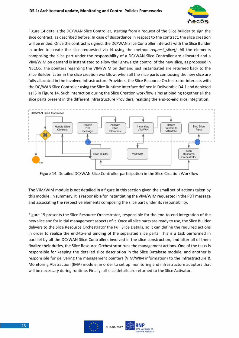
Figure 14 details the DC/WAN Slice Controller, starting from a request of the Slice builder to sign the
slice contract, as described before. In case of discordance in respect to the contract, the slice creation
will be ended. Once the contract is signed, the DC/WAN Slice Controller interacts with the Slice Builder
in order to create the slice requested via I4 using the method request_slice(). All the elements
composing the slice part under the responsibility of a DC/WAN Slice Controller are allocated and a
VIM/WIM on demand is instantiated to allow the lightweight control of the new slice, as proposed in
NECOS. The pointers regarding the VIM/WIM on demand just instantiated are returned back to the
Slice Builder. Later in the slice creation workflow, when all the slice parts composing the new slice are
fully allocated in the involved Infrastructure Providers, the Slice Resource Orchestrator interacts with
the DC/WAN Slice Controller using the Slice Runtime Interface defined in Deliverable D4.1 and depicted
as I5 in Figure 14. Such interaction during the Slice Creation workflow aims at binding together all the
slice parts present in the different Infrastructure Providers, realizing the end‐to‐end slice integration.
Figure 14. Detailed DC/WAN Slice Controller participation in the Slice Creation Workflow.
The VIM/WIM module is not detailed in a figure in this section given the small set of actions taken by
this module. In summary, it is responsible for instantiating the VIM/WIM requested in the PDT message
and associating the respective elements composing the slice part under its responsibility.
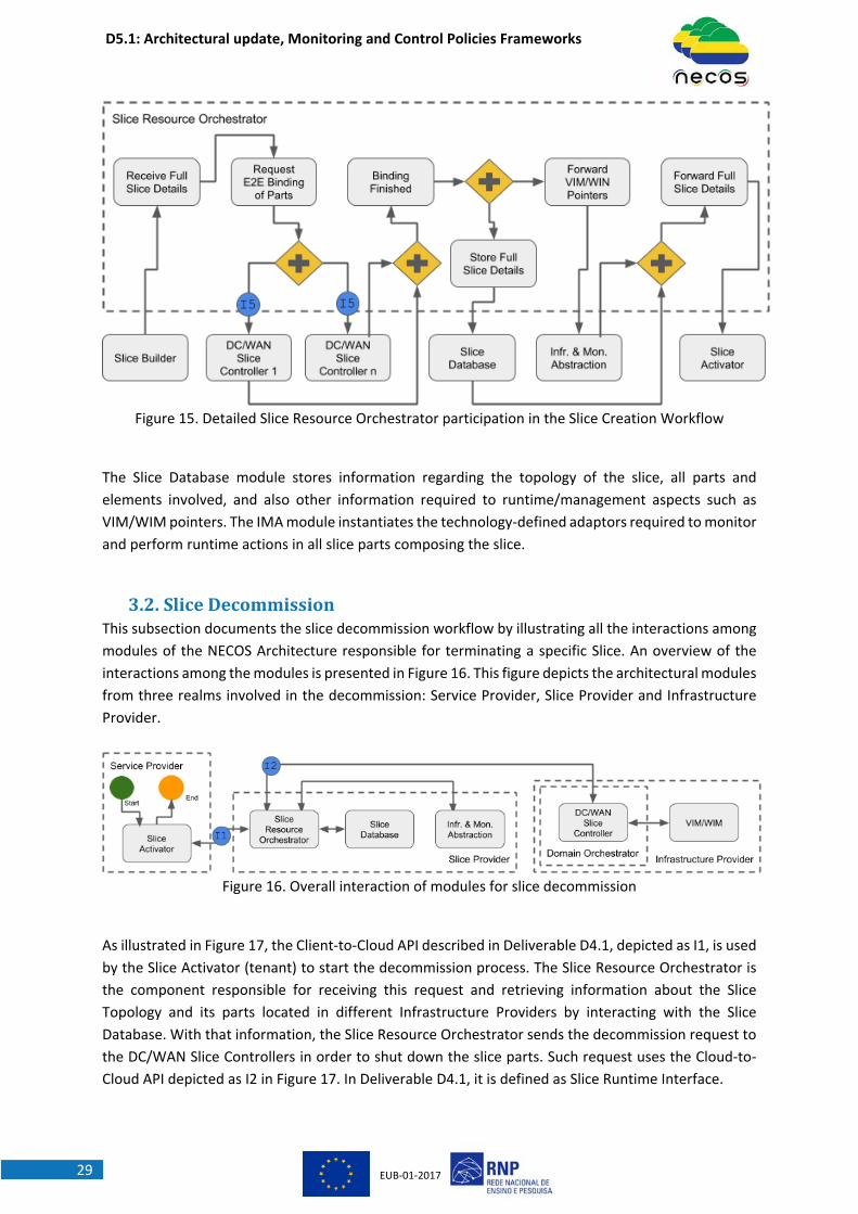
Figure 15 presents the Slice Resource Orchestrator, responsible for the end‐to‐end integration of the
new slice and for initial management aspects of it. Once all slice parts are ready to use, the Slice Builder
delivers to the Slice Resource Orchestrator the Full Slice Details, so it can define the required actions
in order to realize the end‐to‐end binding of the separated slice parts. This is a task performed in
parallel by all the DC/WAN Slice Controllers involved in the slice construction, and after all of them
finalize their duties, the Slice Resource Orchestrator runs the management actions. One of the tasks is
responsible for keeping the detailed slice description in the Slice Database module, and another is
responsible for delivering the management pointers (VIM/WIM information) to the Infrastructure &
Monitoring Abstraction (IMA) module, in order to set up monitoring and infrastructure adaptors that
will be necessary during runtime. Finally, all slice details are returned to the Slice Activator.
D5.1: Architectural update, Monitoring and Control Policies Frameworks
EUB‐01‐201729
Figure 15. Detailed Slice Resource Orchestrator participation in the Slice Creation Workflow
The Slice Database module stores information regarding the topology of the slice, all parts and
elements involved, and also other information required to runtime/management aspects such as
VIM/WIM pointers. The IMA module instantiates the technology‐defined adaptors required to monitor
and perform runtime actions in all slice parts composing the slice.
3.2. SliceDecommissionThis subsection documents the slice decommission workflow by illustrating all the interactions among
modules of the NECOS Architecture responsible for terminating a specific Slice. An overview of the
interactions among the modules is presented in Figure 16. This figure depicts the architectural modules
from three realms involved in the decommission: Service Provider, Slice Provider and Infrastructure
Provider.
Figure 16. Overall interaction of modules for slice decommission
As illustrated in Figure 17, the Client‐to‐Cloud API described in Deliverable D4.1, depicted as I1, is used
by the Slice Activator (tenant) to start the decommission process. The Slice Resource Orchestrator is
the component responsible for receiving this request and retrieving information about the Slice
Topology and its parts located in different Infrastructure Providers by interacting with the Slice
Database. With that information, the Slice Resource Orchestrator sends the decommission request to
the DC/WAN Slice Controllers in order to shut down the slice parts. Such request uses the Cloud‐to‐
Cloud API depicted as I2 in Figure 17. In Deliverable D4.1, it is defined as Slice Runtime Interface.
D5.1: Architectural update, Monitoring and Control Policies Frameworks
EUB‐01‐201730
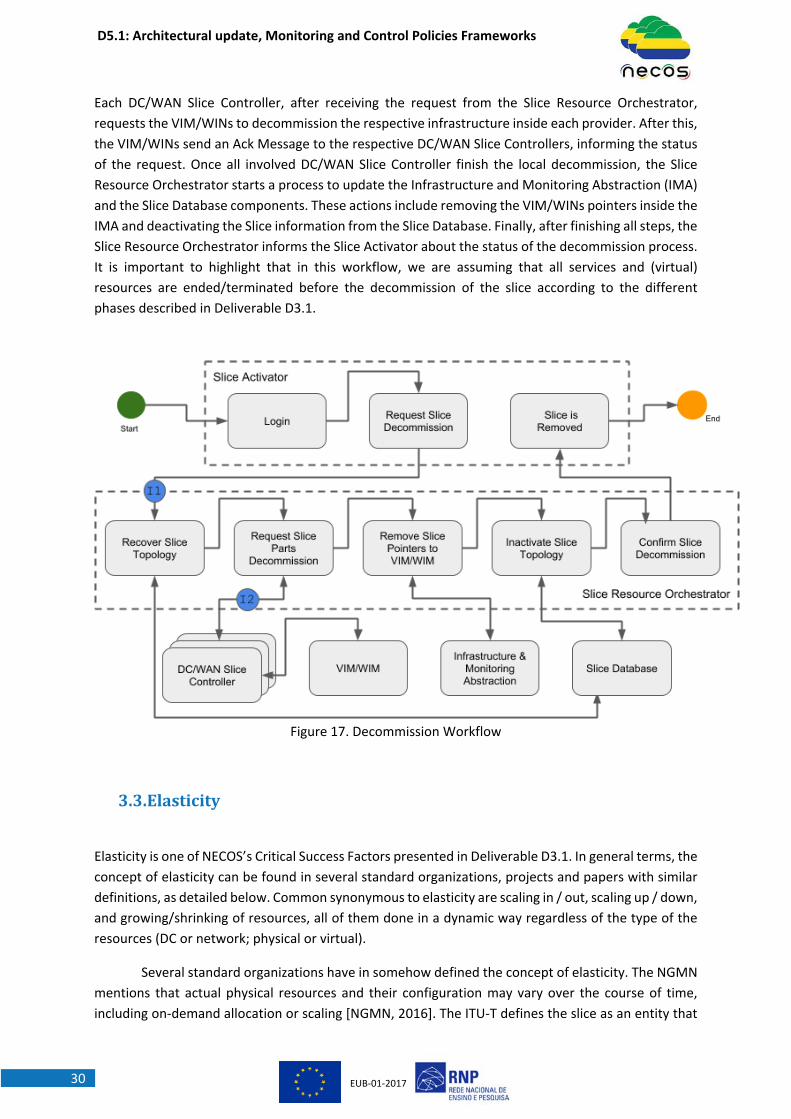
Each DC/WAN Slice Controller, after receiving the request from the Slice Resource Orchestrator,
requests the VIM/WINs to decommission the respective infrastructure inside each provider. After this,
the VIM/WINs send an Ack Message to the respective DC/WAN Slice Controllers, informing the status
of the request. Once all involved DC/WAN Slice Controller finish the local decommission, the Slice
Resource Orchestrator starts a process to update the Infrastructure and Monitoring Abstraction (IMA)
and the Slice Database components. These actions include removing the VIM/WINs pointers inside the
IMA and deactivating the Slice information from the Slice Database. Finally, after finishing all steps, the
Slice Resource Orchestrator informs the Slice Activator about the status of the decommission process.
It is important to highlight that in this workflow, we are assuming that all services and (virtual)
resources are ended/terminated before the decommission of the slice according to the different
phases described in Deliverable D3.1.
Figure 17. Decommission Workflow
3.3. Elasticity
Elasticity is one of NECOS’s Critical Success Factors presented in Deliverable D3.1. In general terms, the
concept of elasticity can be found in several standard organizations, projects and papers with similar
definitions, as detailed below. Common synonymous to elasticity are scaling in / out, scaling up / down,
and growing/shrinking of resources, all of them done in a dynamic way regardless of the type of the
resources (DC or network; physical or virtual).
Several standard organizations have in somehow defined the concept of elasticity. The NGMN
mentions that actual physical resources and their configuration may vary over the course of time,
including on‐demand allocation or scaling [NGMN, 2016]. The ITU‐T defines the slice as an entity that

D5.1: Architectural update, Monitoring and Control Policies Frameworks
EUB‐01‐201731
needs to be dynamic. The slice lifecycle management of ITU‐T includes the elasticity function which
should be capable of giving or removing physical and virtual resources to a slice [ITU‐T, 2016]. ONF
clearly defines that the resources may be sliced dynamically to attend the requirements of the clients.
There is a controller responsible for continually adapting the resources based on the load and on the
policy constraints [ONF, 2016].
The elasticity is also an important feature for 3GPP. The specifications define that a Network
Slice Instance (NSI) can change its capacity. An NSI is formed by network functions and then, if capacity
change is needed for a given network function the operator may need to change the capacity of the
NSI as well [3GPP, 2018a]. 3GPP also specified an overall procedure for modifying an existing NSI
[3GPP, 2018b]. ETSI has similar definition about the lifecycle management in which the NFV‐MANO is
in charge of scaling an underlying NS (Network Service) to expand an NSI.
There are also some previous projects that have included the concept of elasticity (or its
synonymous). We can cite SONATA [SONATA, 2017], 5GeX [5GeX, 2016], SLICENET [SLICENET, 2017]
and PAGODA [PAGODA, 2019]. All of them have specified a way for giving or removing capacity to the
slices.
In the NECOS Project, elasticity is defined as the degree to which a system is able to adapt to
workload changes by provisioning and de‐provisioning resources (computing, networking and storage)
in an autonomic manner, such that at each point in time the available resources match the current
demand as closely as possible. More than that, in the NECOS Project, this elasticity considers that the
slice is provisioned in a multi‐domain and multi‐technological environment and the run‐time change
of resources as such requires a sophisticated mechanism for orchestration.
We also defined the vertical and horizontal elasticity attending to a clearer meaning that
emerged as the work advanced. In line with the literature for resource virtualization [ETSI, 2019] [ONF,
2016], in NECOS we define vertical elasticity as the ability of resizing slice parts dynamically as needed
to adapt to workload changes. For example, this expresses the ability to augment the number of hosts
available in a particular slice of a data center when the demand of the services supported by the slice
increases. We call horizontal elasticity the ability of creating or removing slice parts dynamically, using
resources of the same or other(s) provider(s), following the need to adapt to the workload evolution.
For example, as the service workload increases and the resources available for its supporting slice at a
particular data center are not enough to cope with the needed computing power, it may be possible
to scale out resources creating new slice parts (e.g., a new on‐demand VIM) in another data center
and connecting them appropriately (e.g., creating a new networking slice part).
However, in the NECOS Project, elasticity is not only a matter of increasing or decreasing cloud
network resources. When vertical or horizontal elasticity is accomplished, it is necessary to have all the
NECOS management plane, mainly the SRO, Slice Builder and IMA components working together to
update the information about the resources and slice parts. In general terms, we can see the elasticity
as a three‐dimension feature: elasticity of resources, elasticity of services and elasticity of the
management plane. These three dimensions need to be scaled up and down as necessary to attend
the E2E elasticity. It is required that, for example, the IMA layer receives the new pointer to manage a
new resource added to a given slice part or the new pointer to a new slice part. Also, in terms of
monitoring, new agents need to be instantiated in every new slice part as well as new monitoring
collectors, aggregators and adaptors are created. Therefore, this type of elasticity which also scales up
D5.1: Architectural update, Monitoring and Control Policies Frameworks
EUB‐01‐201732
and down the components of the management plane is novel and different when compared to
previous mechanisms for elasticity.
Some of the benefits of slice elasticity are the capability of allocating on‐demand resources
based on the service load and KPIs, dynamic adjustment of the resources, improved capacity planning
for the provider and optimization of the profit and performance to tenants as well as to infrastructure
providers. In the following subsections, we present the high‐level workflows for slice elasticity in terms
of upgrading and downgrading of resources.
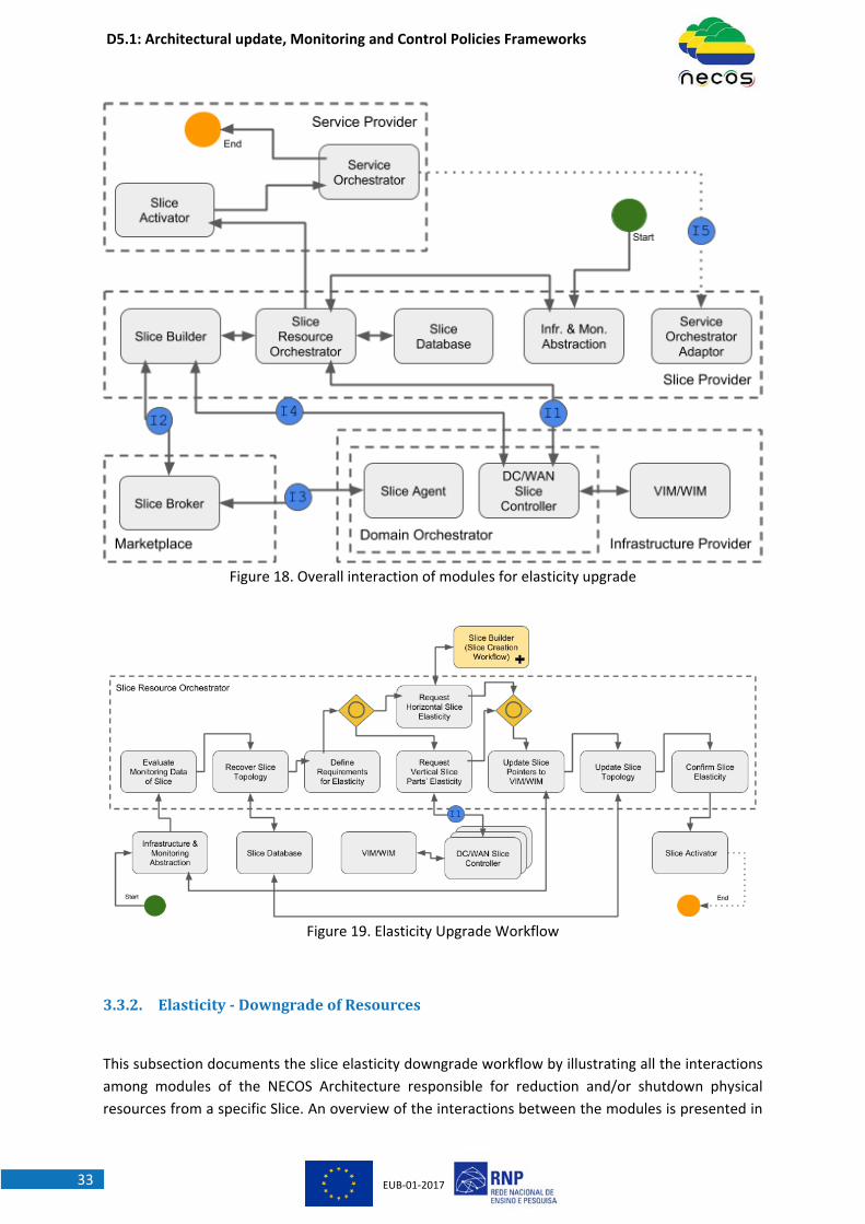
3.3.1. Elasticity‐UpgradeofResources
This subsection documents the slice elasticity upgrade workflow by illustrating all the interactions
among modules of the NECOS Architecture responsible for growing a specific slice. An overview of the
interactions between the modules is presented in Figure 18. This figure depicts the architectural
modules from four realms involved in the upgrade: Service Provider, Slice Provider, Infrastructure
Provider and Marketplace.
The workflow presented in Figure 19 details both vertical and horizontal elasticity. First, the SRO checks
if a specific Slice needs to grow by analysing monitoring metrics. Assuming that a Slice Part is
overloaded, the SRO tries vertical scaling with the respective DC/WAN Slice Controller, using the Slice
Runtime Interface depicted as I1 in Figure 19. The method to be invoked is the add_element(). The
DC/WAN Slice Controller will return to the SRO the status and the information about the process. If
the Slice Part is not able to instantiate more resources (vertical scaling), a horizontal scaling is
necessary.
The horizontal elasticity process is very similar to the create slice workflow. Basically, the SRO needs
to communicate with the Slice Builder to follow the steps presented previously in Figures 11‐16. The
Slice Builder instantiates the new Slice Part by communicating with the DC/WAN Slice Controller, using
the Slice Instantiation Interface. To finish this process, the SRO receives the status and the pointer to
the new Slice Part; glues this new part to the Slice and updates the slice information in the IMA and in
the Slice Database.
Finally, the SRO informs the Slice Activator about the elasticity just performed, since the Service
Provider (tenant) might request the Service Orchestrator to adapt the service to the new slice
arrangement. Figure 18 shows this final step as a dotted line since it is left for future investigations in
Deliverable D5.2
D5.1: Architectural update, Monitoring and Control Policies Frameworks
EUB‐01‐201733
Figure 18. Overall interaction of modules for elasticity upgrade
Figure 19. Elasticity Upgrade Workflow
3.3.2. Elasticity‐DowngradeofResources
This subsection documents the slice elasticity downgrade workflow by illustrating all the interactions
among modules of the NECOS Architecture responsible for reduction and/or shutdown physical
resources from a specific Slice. An overview of the interactions between the modules is presented in

D5.1: Architectural update, Monitoring and Control Policies Frameworks
EUB‐01‐201734
Figure 20. This figure depicts the architectural modules from three realms involved in the elasticity
downgrade: Service Provider, Slice Provider and Infrastructure Provider.
As illustrated in Figure 21, the process starts from the IMA component collecting monitoring metrics.
The SRO evaluates these metrics and detects whether it is necessary to downgrade an idle resource or
not. After identifying the need of slice downgrade, the SRO retrieves information related to the
respective Slice Part from the Slice Database in order to define which slice parts should be adapted.
Next, the SRO requests reduction and/or removal to the DC/WAN Slice Controller via the Slice Runtime
Interface as depicted in I1. As described in Deliverable D4.1, these operations could be supported using
two methods defined on the Cloud‐to‐Cloud API: update_slice() method for decreasing the resources
of the slice and the delete_slice() method for the deletion of the slice.
The DC/WAN Slice Controller communicates with the VIM/WIM in order to decrease or shutdown the
resources. The SRO receives the confirmation from the DC/WAN Slice Controller and updates the
information into the IMA and the Slice Database.
Finally, the Slice Resource Orchestrator informs the Service Provider (tenant) about the elasticity
performed. This is a process that also requires further refinements in the project and more details will
be in Deliverable D5.2
Figure 20. Overall interaction of modules for elasticity downgrade
Figure 21. Elasticity Downgrade Workflow
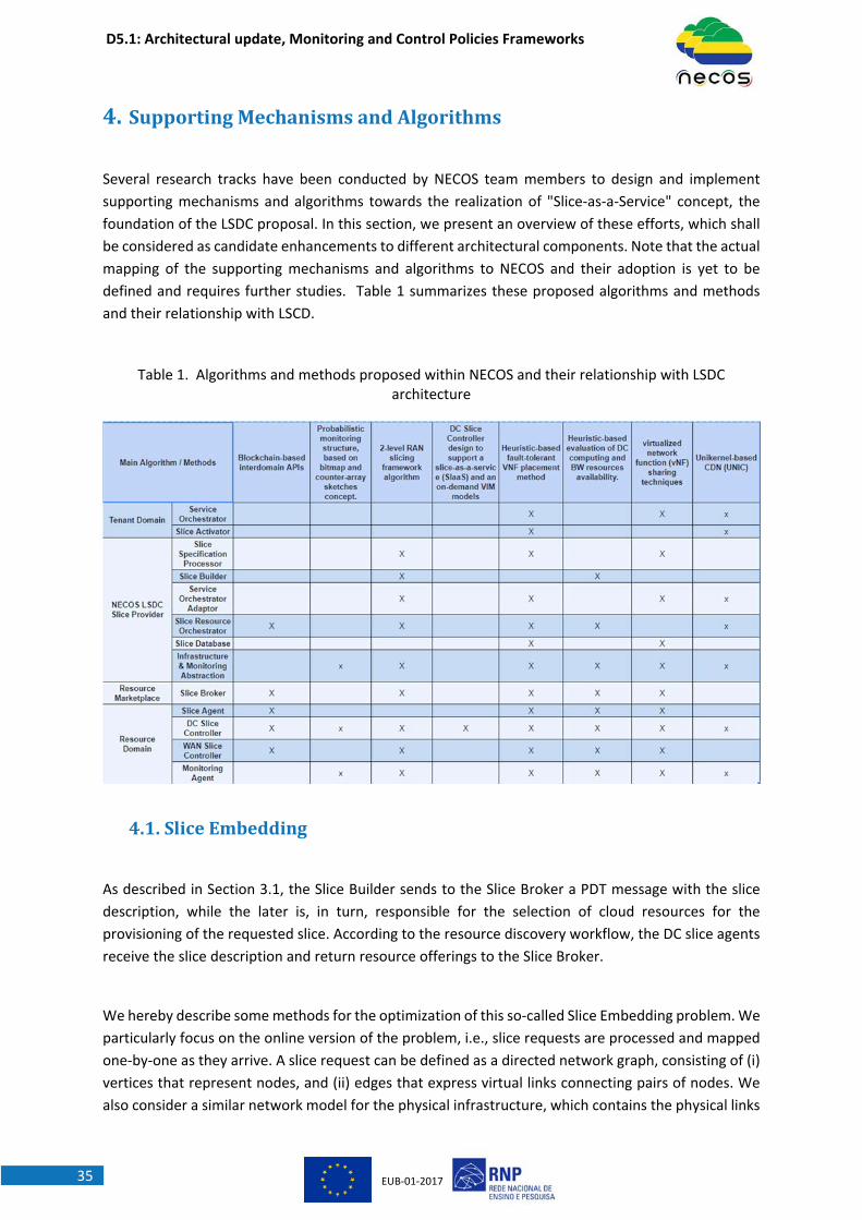
D5.1: Architectural update, Monitoring and Control Policies Frameworks
EUB‐01‐201735
4. SupportingMechanismsandAlgorithms
Several research tracks have been conducted by NECOS team members to design and implement
supporting mechanisms and algorithms towards the realization of "Slice‐as‐a‐Service" concept, the
foundation of the LSDC proposal. In this section, we present an overview of these efforts, which shall
be considered as candidate enhancements to different architectural components. Note that the actual
mapping of the supporting mechanisms and algorithms to NECOS and their adoption is yet to be
defined and requires further studies. Table 1 summarizes these proposed algorithms and methods
and their relationship with LSCD.
Table 1. Algorithms and methods proposed within NECOS and their relationship with LSDC architecture
4.1. SliceEmbedding
As described in Section 3.1, the Slice Builder sends to the Slice Broker a PDT message with the slice
description, while the later is, in turn, responsible for the selection of cloud resources for the
provisioning of the requested slice. According to the resource discovery workflow, the DC slice agents
receive the slice description and return resource offerings to the Slice Broker.
We hereby describe some methods for the optimization of this so‐called Slice Embedding problem. We
particularly focus on the online version of the problem, i.e., slice requests are processed and mapped
one‐by‐one as they arrive. A slice request can be defined as a directed network graph, consisting of (i)
vertices that represent nodes, and (ii) edges that express virtual links connecting pairs of nodes. We
also consider a similar network model for the physical infrastructure, which contains the physical links

D5.1: Architectural update, Monitoring and Control Policies Frameworks
EUB‐01‐201736
and the various types of nodes (e.g., servers, routers, switches) defined in the NECOS information
model (see Deliverable D3.1). In essence, slice embedding aims to generate a near‐optimal mapping
of slice nodes to servers, and slice graph edges to cloud network paths. We refrain from designing
naive embedding solutions that decouple node from link mapping, and thereby, lead to resource
inefficiencies and potential slice request rejections. Instead, we aim at a coordinated slice node and
link mapping, by jointly examining node and link constraints, which would eventually lead to efficient
embeddings.
Slice embedding can be optimized based on different objectives, such as the minimization of
embedding footprint, load balancing, and the minimization of client’s expenditure. In the presence of
a single cloud provider, the embedding would be carried out by the provider himself based on his own
policy (e.g., footprint minimization or load balancing). However, NECOS anticipates the presence of
multiple cloud providers that may either compete for slice offerings or may alternatively establish
federations. The latter entails a larger degree of information disclosure, as opposed to a competition
scenario at which there will be a lack of trust among cloud providers and the Slice Broker.
To circumvent the difficulty of multi‐provider slice embedding, we decompose the embedding problem
into two steps. Before explaining these steps, we note that we consider that the resource offerings
sent from the Slice Agents are sufficiently abstract, such that no confidential information is being
exposed. For example, the provider can advertise a resource type, which is not bound to any particular
physical resource, hence, avoiding the exposure of confidential information. Similarly, certain virtual
links may be also advertised that do not expose any information about the substrate network topology.
With such resource offerings in mind, slice embeddings are generated as a sequence of the following
steps:
The Slice Broker receives a set of resource types and virtual links from DC slice and WAN
agents, in response to a slice request previously submitted to all involved agents. The Slice
Broker inserts all advertised information into his embedder, which generates coarse‐grained
embeddings by mapping slice components onto the resources and virtual links offered by the
various agents. This 1‐level embedding can be optimized with regards to the client’s
expenditure, i.e., seek the cheapest embedding that fulfils the client’s requirements.
Since the 1‐level embedding generated by the Slice Broker does not lead to exact mappings
(since the resource offerings are not bound to specific physical resources), each Slice Agent
receives from the Slice Broker the embedding result that corresponds to his own resources,
and subsequently proceeds with the Binding step. This step essentially consists in the binding
of resource offering to specific resources, leading to fine‐grained embeddings.
Consequently, this two‐stage embedding framework is well suited the NECOS multi‐provider Slice‐as‐
a‐Service ecosystem, as it allows for efficient and low‐cost embeddings while preserving the
confidentiality of resource and network topology information of cloud providers. The 1‐level
embedding can be formulated as a linear program that strives to minimize the client’s expenditure,
while ensuring that slice constraints will be met. With respect to such constraints, we consider capacity
constraints more relevant for the Binding step, as we expect that resource availability will not be
D5.1: Architectural update, Monitoring and Control Policies Frameworks
EUB‐01‐201737
disclosed to the Slice Broker. Instead, the 1‐level embedding will mainly deal with geolocation and
functional constraints (e.g., node type, OS, link type, etc.).
The Binding stage can be formulated as a multi‐commodity flow problem, aiming to generate near‐
optimal mappings with respect to the provider’s resource allocation policy (e.g., embedding footprint
minimization or load balancing). This policy will be expressed in the objective function, while the
formulation constraints will mainly deal with the associated capacity constraints.
Another contribution relies on WISE (WLAN slIcing as a SErvice) approach [CARMO, 2018] to evolve
current WLAN‐shared technology while addressing the challenges of efficiently affording the rising of
the massive mobile data demand in UDN 5G use cases. WISE expands the computational capabilities
of the WLAN‐sharing CPEs through applying Fog computing technology in order to support slice‐based
definitions. The main idea behind a slice‐defined WLAN‐sharing CPE is to provide differentiated
services on top of the same infrastructure through customized, isolated and independent digital
building blocks. Finally, slices are enabled to accommodate applications in addition to network
functions, so as to afford offering ultra‐low latency rates by direct linkage to data producer things. The
feasibility of the proposal is assessed via experiments in a real testbed, allowing insights in its proof of
concept.
In addition, NECOS team has proposed an end‐to‐end LTE slice embedding framework [PAPAGIANNI,
2018] in order to map LTE service chains (i.e., composed of virtualized LTE data and control plane
elements, such as Service Gateways, PDN gateways, Mobile Management Entities, etc.) onto cloud
infrastructures. A novel aspect of the proposed framework is that it promotes LTE network function
(NF) sharing across multiple service chains in a network slice in order to alleviate the increased
overheads associated with NF provisioning and management, while reducing the amount of NF state
that has to be maintained and the magnitude of resource fragmentation. The embedding problem has
been formulated as mixed integer linear program (MILP) and is shown to yield significant gains for low
and medium utilization levels.
4.2. SliceIsolationandElasticity
The “slicing” computing and communication resources encloses the idea of sharing, with some
granularity, those resources. Depending on the “mode” (as defined in D3.1) in which NECOS may work,
that sharing may be at the host level, at the datacentre level, or other possible units. This makes an
efficient use of the expertise of the provider in building, managing, and improving common services,
and enable the statistical multiplexing of resources between tenants for higher utilization. As described
in [SHUE, 2012] these services using shared resources face two issues:
Multi‐tenant interference and unfairness: Tenants simultaneously accessing shared services
contend for resources and degrade performance.
Variable and unpredictable performance: Tenants often experience significant performance
variations, e.g., in response time or throughput, even when they can achieve their desired
mean rate.
Therefore, some tenants can pay for performance isolation and predictability, while others may
choose standard “best‐effort” behaviour. We understand performance isolation as defined in [KREBS,
2014]: “A system is performance‐isolated, if for customers working within their quotas the
D5.1: Architectural update, Monitoring and Control Policies Frameworks
EUB‐01‐201738
performance is not affected when other customers exceed their quotas. A decreasing performance for
the customers exceeding their quotas is fair.”
As part of NECOS’ work, a 2‐level RAN slicing framework was proposed to address the limitation in
literature of slicing solutions for heterogamous future networks, i.e. 5G, RAN [KIBALYA, 2018]. This
work presents a threefold novel concept of slice profiles capable of: (i) ensuring the safeguard of slices
against inter‐slice interference by Isolation, (ii) enabling Authentication, and (iii) providing Elasticity.
These characteristics ensure flexible and dynamic allocation, by reclaiming and releasing resources in
order to optimize both temporal and spatial resource usage. With mere preciseness, the work
proposes a practical RAN slicing framework with dynamic and intelligent two‐level (LSM, DSM)
resource sharing algorithm, capable of capturing dynamic properties of slice conditions based on a
dynamic online resource sharing policy for sharing resources across multiple domains within
heterogeneous network environments.
Regarding elasticity methods, our work on Unikernel‐based CDN (UNIC) proposes a CDN platform,
which places micro‐content proxies near the users [VALSAMAS, 2018]. Proof‐of‐concept experimental
results show UNIC most relevant features: modular orchestration of VM hosting replicas of Internet
content, a Change‐Point Detection (CPD)‐based mechanism to detect content popularity changes, a
DNS‐based dynamic load balancing, and real‐time monitoring of server resource utilization and end‐
user performance.
The work on change point (CP) analysis to early video content popularity detection [SKAPERAS, 2018]
is highly related with a number of NECOS technical enablers, such as: flexible network technologies for
traffic load balancing, network monitoring facilities for intelligent decisions for services’ deployment /
management, efficient slice operation and, finally, lightweight virtualization technologies for hosting
Content Distribution (CD) services on the edge cloud. The proposed change point (CP) analysis is a
directly applicable mechanism in our project, since it can trigger elasticity capabilities for enabling
intelligent monitoring in the Information and Monitoring Abstraction (IMA) component of the NECOS
Slice Provider.
4.3. FaulttoleranceTo enhance fault tolerance of virtual network functions (VNF) running in virtual machines (VM), the
standby VNF instances need to be deployed and synced constantly with the state update, which could
consume considerable network bandwidth leading to link overhead. Thus, it is presented in [YANG,
2018] an efficient solution, to the fault‐tolerant VNF placement problems, a heuristic algorithm that
jointly computes the placement active and stand‐by instances of stateful VNFs, the routing paths and
update paths of user requests, therefore, significantly maximize the request admission rate and further
evaluated outperforming the existing solutions that separately determine placements, routings and
state update paths, in terms of DC resource utilization, cost and runtime.
4.4. MonitoringThe probabilistic monitoring structure, based on bitmap and counter‐array sketches concept in
[MARTINS, 2018], allows to reduce the computational cost associated with the detailed collecting of
information in the network and can get traffic statistics requiring a fixed size memory with controlled
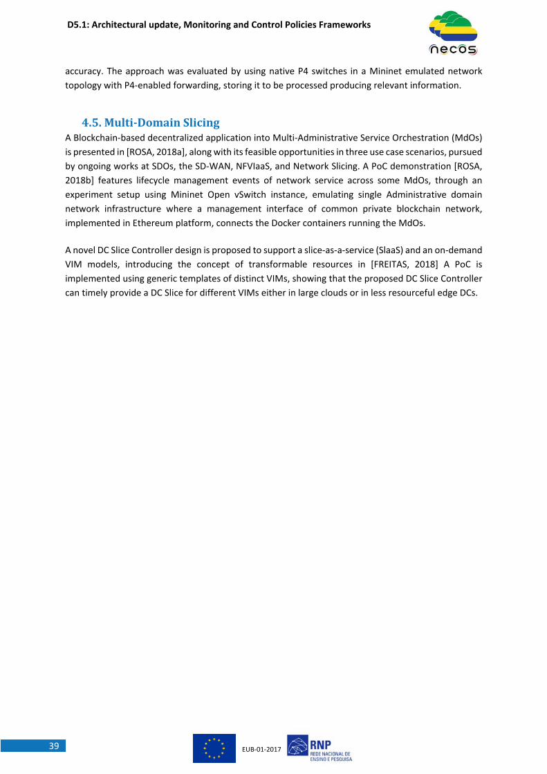
D5.1: Architectural update, Monitoring and Control Policies Frameworks
EUB‐01‐201739
accuracy. The approach was evaluated by using native P4 switches in a Mininet emulated network
topology with P4‐enabled forwarding, storing it to be processed producing relevant information.
4.5. Multi‐DomainSlicingA Blockchain‐based decentralized application into Multi‐Administrative Service Orchestration (MdOs)
is presented in [ROSA, 2018a], along with its feasible opportunities in three use case scenarios, pursued
by ongoing works at SDOs, the SD‐WAN, NFVIaaS, and Network Slicing. A PoC demonstration [ROSA,
2018b] features lifecycle management events of network service across some MdOs, through an
experiment setup using Mininet Open vSwitch instance, emulating single Administrative domain
network infrastructure where a management interface of common private blockchain network,
implemented in Ethereum platform, connects the Docker containers running the MdOs.
A novel DC Slice Controller design is proposed to support a slice‐as‐a‐service (SlaaS) and an on‐demand
VIM models, introducing the concept of transformable resources in [FREITAS, 2018] A PoC is
implemented using generic templates of distinct VIMs, showing that the proposed DC Slice Controller
can timely provide a DC Slice for different VIMs either in large clouds or in less resourceful edge DCs.

D5.1: Architectural update, Monitoring and Control Policies Frameworks
EUB‐01‐201740
5. ConclusionsandOutlookThis deliverable describes the initial design for the components of the NECOS architecture. The internal
functions of each component and their responsibilities are presented so that it is possible to better
understand how each component works. This document also presents the workflows among these
components necessary to support the slice creation, slice elasticity and slice decommission. Such flows
guide the reader to a step‐by‐step interaction among the components using BPMN modelling so that
a high level view of the whole process can be captured. Finally, this deliverable presents a set of
algorithms and supporting mechanisms that can be useful for the next steps of the NECOS project
mainly in the sense of realizing the "Slice‐as‐a‐Service" concept.
The next deliverable, D5.2, should provide a consolidated view about the different designs and
candidate implementations presented in this document as well as a complementary set of workflows
for other scenarios not addressed in this deliverable. Also, the workflows described in this document
can be revisited for better linking with real implementations being done by the project partners.

D5.1: Architectural update, Monitoring and Control Policies Frameworks
EUB‐01‐201741
6. References
[SC1] Stavropoulos, Donatos, et al. "Design, architecture and implementation of a resource discovery,
reservation and provisioning framework for testbeds." Modeling and Optimization in Mobile, Ad Hoc,
and Wireless Networks (WiOpt), 2015 13th International Symposium on. IEEE, 2015.
[SC2] SOLO ‐ SDN Overlay Orchestrator. https://git.rnp.br/sdn‐overlay/sdn‐overlay‐orchestrator,
2018. [Online; accessed 28‐September‐2018].
[CARMO, 2018] M. Carmo, S. Jardim, A. Neto, R. Aguiar, D. Corujo, J. Rodrigues. Slicing WiFi WLAN‐
Sharing Access Infrastructures to Enhance Ultra‐Dense 5G Networking. IEEE ICC 2018, Kansas City, MO,
USA, 20‐24 May 2018.
[KIBALYA, 2018] Godfrey Kibalya, Joan Serrat and Juan‐Luis Gorricho. RAN Slicing Framework and
Resource Allocation in Multi‐Domain Heterogeneous Networks. IFIP AIMS 2018 conference, June 2018.
[VALSAMAS, 2018] P.Valsamas, S.Skaperas and L.Mamatas. Elastic Content Distribution Based on
Unikernels and Change Point Analysis. IEEE Wireless 2018, Catania, Italy, May 2018.
[YANG, 2018] B. Yang , Z. Xu, W. K. Chai, W. Liang, D. Tuncer, A. Galis, and G. Pavlou. Algorithms for
Fault‐Tolerant Placement of Stateful Virtualized Network Functions. IEEE ICC 2018, Kansas City, MO,
USA, 20‐24 May 2018.
[MARTINS, 2018] Regis Martins, Luis Garcia, Rodolfo Villaça and Fábio L. Verdi. Using Probabilistic Data
Structures for Monitoring of Multi‐tenant P4‐based Networks. IEEE ISCC 2018 Conference, June 2018.
[ROSA, 2018a] Raphael Vicente Rosa, Christian Esteve Rothenberg. “Blockchain‐based Decentralized
Applications for Multiple Administrative Domain Networking, In IEEE Communications Standards
Magazine, Sep. 2018.
[ROSA, 2018b] Raphael Vicente Rosa, Christian Esteve Rothenberg. Blockchain‐based Decentralized
Applications meet Multi‐Administrative Domain Networking. ACM SIGCOMM 2018 Poster and Demo
Session, [Demo Video], August 2018.
[FREITAS, 2018] L. Freitas, V. Braga, S. L. Correa, L. Mamatas, C. Esteve Rothenberg, S. Clayman, and K.
Cardoso. Slicing and Allocation of Transformable Resources for the Deployment of Multiple Virtualized
Infrastructure Managers (VIMs). In Workshop on advances in slicing for softwarized infrastructures
(S4SI 2018) – IEEE conference on network softwarization (NETSOFT), June 2018.
[SKAPERAS, 2018] S. Skaperas, L. Mamatas and A. Chorti, “Early Video Content Popularity Detection
with Change Point Analysis”, IEEE GLOBECOM 2018, 9‐13 December, Abu Dhabi, UAE.
[PAPAGIANNI, 2018] C. Papagianni, P. Papadimitriou, and J. Baras. Rethinking Service Chain Embedding
for Cellular Network Slicing. IFIP/IEEE Networking 2018, Zurich, Switzerland, May 2018.
D5.1: Architectural update, Monitoring and Control Policies Frameworks
EUB‐01‐201742
[KREBS, 2014] Krebs, R., Momm, C., & Kounev, S. (2014). Metrics and techniques for quantifying
performance isolation in cloud environments. Science of Computer Programming, 90(PART B), 116–
134. https://doi.org/10.1016/j.scico.2013.08.003.
[SHUE, 2012] Shue, D., Freedman, M. J., & Shaikh, A. (2012). Performance Isolation and Fairness for
Multi‐Tenant Cloud Storage. In Proceedings of the 10th USENIX Conference on Operating Systems
Design and Implementation (Vol. 12, p. 349). Retrieved from
https://www.usenix.org/system/files/conference/osdi12/osdi12‐final‐215.pdf.
[NGMN, 2016] NGMN 5G P1 Requirements & Architecture Work Stream End‐to‐End Architecture.
Description of Network Slicing Concept.
[ITU‐T, 2016] Draft Recommendation: Network Management Framework for IMT‐2020. IMT‐O‐047.
[ONF, 2016] TR‐526 Applying SDN Architecture to 5G Slicing.
[3GPP, 2018a] 3GPP TR 28.801 V15.1.0 (2018‐01). 3rd Generation Partnership Project;Technical
Specification Group Services and System Aspects; Telecommunication management; Study on
management and orchestration of network slicing for next generation network, (Release 15).
[3GPP, 2018b] 3GPP TS 28.531 V16.0.0 (2018‐12). 3rd Generation Partnership Project; Technical
Specification Group Services and System Aspects; Management and orchestration; Provisioning;
(Release 16).
[ETSI, 2019] Network Functions Virtualisation (NFV) Release 3; Management and Orchestration;
Requirements and interfaces specification for management of NFV‐MANO.
[SONATA, 2016] https://sonata‐project.org/.
[5Gex, 2016] http://www.5gex.eu/.
[SLICENET, 2017] https://slicenet.eu/.
[PAGODA, 2019] https://5g‐pagoda.aalto.fi/.
Version History
Version Date Author Change record
0.1 10.10.2018 Fábio L. Verdi Creation
0.2 15.10.2018 Fábio L. Verdi First integrated draft after internal review
1.0 17.10.2018 Fábio L. Verdi Final version release
1.1 18.02.2019 Fábio L. Verdi and Javier Baliosian
Reviewers comments addressed
1.2 08.03.2019 Fábio L. Verdi Integrated version after internal review
1.3 11.03.2019 Fábio L. Verdi Final version release