d4f small safety limit switch datasheet - farnell element14 · d4f 3 characteristics note: 1. the...
TRANSCRIPT
C73I-E-02
1
Small Safety Limit Switch
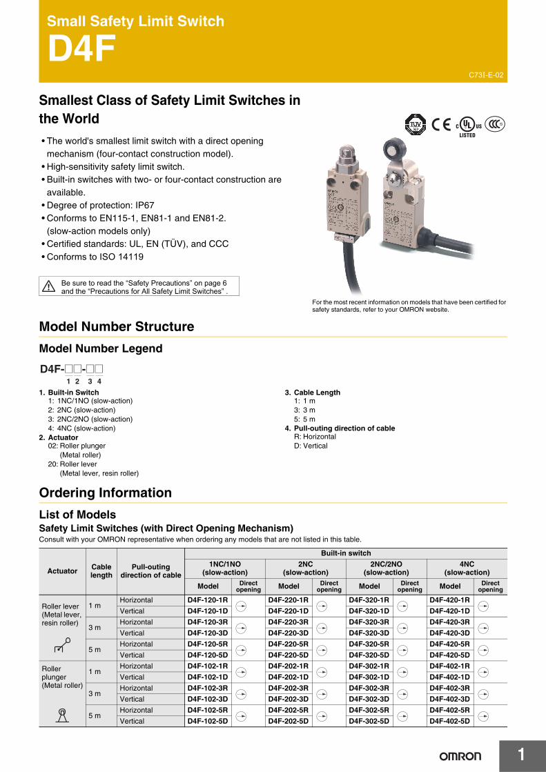
D4FSmallest Class of Safety Limit Switches in the World
• The world's smallest limit switch with a direct openingmechanism (four-contact construction model).
• High-sensitivity safety limit switch.• Built-in switches with two- or four-contact construction are
available.• Degree of protection: IP67• Conforms to EN115-1, EN81-1 and EN81-2.
(slow-action models only)• Certified standards: UL, EN (TÜV), and CCC• Conforms to ISO 14119
Model Number Structure
Model Number Legend
1. Built-in Switch1: 1NC/1NO (slow-action)2: 2NC (slow-action)3: 2NC/2NO (slow-action)4: 4NC (slow-action)
2. Actuator02: Roller plunger
(Metal roller)20: Roller lever
(Metal lever, resin roller)
3. Cable Length1: 1 m3: 3 m5: 5 m
4. Pull-outing direction of cableR: HorizontalD: Vertical
Ordering Information
List of ModelsSafety Limit Switches (with Direct Opening Mechanism)Consult with your OMRON representative when ordering any models that are not listed in this table.
For the most recent information on models that have been certified for safety standards, refer to your OMRON website.
1 2 3 4
D4F-@@-@@
Actuator Cable length
Pull-outing direction of cable
Built-in switch
1NC/1NO (slow-action)
2NC (slow-action)
2NC/2NO (slow-action)
4NC (slow-action)
Model Direct opening Model Direct
opening Model Direct opening Model Direct
opening
Roller lever (Metal lever, resin roller)
1 mHorizontal D4F-120-1R D4F-220-1R D4F-320-1R D4F-420-1R
Vertical D4F-120-1D D4F-220-1D D4F-320-1D D4F-420-1D
3 mHorizontal D4F-120-3R D4F-220-3R D4F-320-3R D4F-420-3R
Vertical D4F-120-3D D4F-220-3D D4F-320-3D D4F-420-3D
5 mHorizontal D4F-120-5R D4F-220-5R D4F-320-5R D4F-420-5R
Vertical D4F-120-5D D4F-220-5D D4F-320-5D D4F-420-5D
Roller plunger (Metal roller)
1 mHorizontal D4F-102-1R D4F-202-1R D4F-302-1R D4F-402-1R
Vertical D4F-102-1D D4F-202-1D D4F-302-1D D4F-402-1D
3 mHorizontal D4F-102-3R D4F-202-3R D4F-302-3R D4F-402-3R
Vertical D4F-102-3D D4F-202-3D D4F-302-3D D4F-402-3D
5 mHorizontal D4F-102-5R D4F-202-5R D4F-302-5R D4F-402-5R
Vertical D4F-102-5D D4F-202-5D D4F-302-5D D4F-402-5D
Be sure to read the “Safety Precautions” on page 6 and the “Precautions for All Safety Limit Switches” .
2
D4F
Specifications
Standards and EC DirectivesConforms to the following EC Directives:• Machinery Directive• Low Voltage Directive• EN50047• EN60204-1• EN ISO 14119• GS-ET-15
Certified Standards
*1.Contact your OMRON sales representative.*2.Certification has been obtained for CSA C22.2 No. 14 under UL.*3.Ask your OMRON representative for information on certified
models.
Certified Standard RatingsTÜV (EN60947-5-1), CCC (GB14048.5)
Note: Use a 10 A fuse type gI or gG that conforms to IEC60269 as a short-circuit protection device.
UL/CSA (UL508, CSA C22.2 No. 14)C300
Q300
Certification body Standards File No.
TÜV SÜD EN60947-5-1 (certified direct opening) *1
UL *2 UL508CSA C22.2 No.14 E76675
CQC (CCC) *3 GB14048.5 20030103050 64266
Item Utilization category AC-15 DC-13
Rated operating current (Ie) 0.75 A 0.27 A
Rated operating voltage (Ue) 240 V 250 V
Rated voltage Carry current
Current (A) Volt-amperes (VA)
Make Break Make Break
120 VAC240 VAC 2.5 A 15
7.51.50.75 1,800 180
Rated voltage Carry current
Current (A) Volt-amperes (VA)
Make Break Make Break
125 VDC250 VDC 2.5 A 0.55
0.270.550.27 69 69
D4F
3
Characteristics
Note: 1. The above values are initial values.2. Once the contact is opened or closed with an ordinary load, it cannot be used for a load smaller than that. The contact surface may be
rough, which impairs the reliability of contacting.*1. The degree of protection shown above is based on the test method specified in EN60947-5-1. Be sure to confirm in advance the sealing
performance under the actual operating environment and conditions.*2.Durability values are calculated at an operating temperature of 5 to 35°C, and an operating humidity of 40% to 70%. Contact your OMRON
sales representative for more detailed information on other operating environments.*3.Do not apply 1 A at 125 VAC to more than two circuits.*4. The value will vary depending on factors such as the switching frequency, the ambient environment, and the reliability level.
Be sure to confirm correct operation with the actual load before application.*5. The contact resistance was measured with 0.1 A at 5 to 8 VDC with a fall-of-potential method.
Degree of protection *1 IP67 (EN60947-5-1)
Durability *2Mechanical 10,000,000 times min.
Electrical 1,000,000 times min. (4 mA resistive load at 24 VDC, 4 circuits)150,000 times min. (1 A resistive load at 125 VAC, 2 circuits/4 mA resistive load at 24 VDC, 2 circuits) *3
Operating speed 1 mm/s to 0.5 m/s
Operating frequencyMechanical 120 operations/minute
Electrical 30 operations/minute
Contact resistance *5 300 mΩ max. (with 1 m cable), 500 mΩ max. (with 3 m cable), 700 mΩ max. (with 5 m cable)
Minimum applicable load *4 4 mA resistive load at 24 VDC, 4 circuits (N-level reference value)
Rated insulation voltage (Ui) 250 V
Rated frequency 50/60 Hz
Protection against electric shock Class I (with a ground wire)
Pollution degree (operating environment) 3 (EN60947-5-1)
Impulse withstand voltage (EN60947-5-1)
Between terminals of same polarity 2.5 kV
Between terminals of different polarity 4 kV
Between each terminal and ground 4 kV
Insulation resistance 100 MΩ min. (at 500 VDC) between terminals of the same polarities, between terminals of different polarities, between current-carrying metal parts and grounds, and between each terminal and non-current carrying metal parts
Contact gap 2 × 2 mm min.
Vibration resistance Malfunction 10 to 55 Hz, 0.75 mm single amplitude
Shock resistanceDestruction 1,000 m/s2 min.
Malfunction 300 m/s2 min.
Conditional short-circuit current 100 A (EN60947-5-1)
Conventional free air thermal current (Ith) 2.5 A (EN60947-5-1)
Ambient operating temperature −30 to 70°C (with no icing)
Ambient operating humidity 95% max.
Cable UL2464 No. 22 AWG, finishing O.D.: 8.3 mm
Weight Approx. 190 g (D4F-102-1R, with 1 m cable)Approx. 220 g (D4F-120-1R, with 1 m cable)
4
D4F
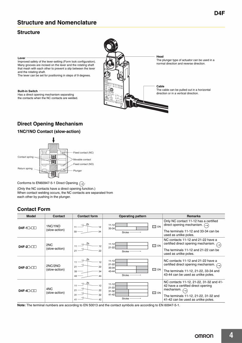
Structure and Nomenclature
Structure
Direct Opening Mechanism1NC/1NO Contact (slow-action)
Conforms to EN60947-5-1 Direct Opening .
(Only the NC contacts have a direct opening function.)When contact welding occurs, the NC contacts are separated from each other by pushing in the plunger.
Contact Form
Note: The terminal numbers are according to EN 50013 and the contact symbols are according to EN 60947-5-1.
Improved safety of the lever-setting (Form lock configuration).Many grooves are incised on the lever and the rotating shaft that mesh with each other to prevent a slip between the lever and the rotating shaft.The lever can be set for positioning in steps of 9 degrees.
The plunger type of actuator can be used in a normal direction and reverse direction.
The cable can be pulled out in a horizontal direction or in a vertical direction.Has a direct opening mechanism separating
the contacts when the NC contacts are welded.
Lever Head
Cable
Built-in Switch
Contact spring
Return spring
Fixed contact (NC)
Movable contact
Fixed contact (NO)
Plunger
Model Contact Contact form Operating pattern Remarks
D4F-1@-@@ 1NC/1NO (slow-action)
Only NC contact 11-12 has a certified direct opening mechanism.
The terminals 11-12 and 33-34 can be used as unlike poles.
D4F-2@-@@ 2NC (slow-action)
NC contacts 11-12 and 21-22 have a certified direct opening mechanism.
The terminals 11-12 and 21-22 can be used as unlike poles.
D4F-3@-@@ 2NC/2NO (slow-action)
NC contacts 11-12 and 21-22 have a certified direct opening mechanism.
The terminals 11-12, 21-22, 33-34 and 43-44 can be used as unlike poles.
D4F-4@-@@ 4NC (slow-action)
NC contacts 11-12, 21-22, 31-32 and 41-42 have a certified direct opening mechanism.
The terminals 11-12, 21-22, 31-32 and 41-42 can be used as unlike poles.
11
33
12Zb
34
ON
Stroke
11-1233-34
11
21
12Zb
22
ON
Stroke
11-1221-22
11
21
33
12Zb
22
34
43 44
ON
21-2211-12
33-3443-44
Stroke
11
21
31
41
12Zb
22
32
42
ON
21-2211-12
31-3241-42
Stroke
D4F
5
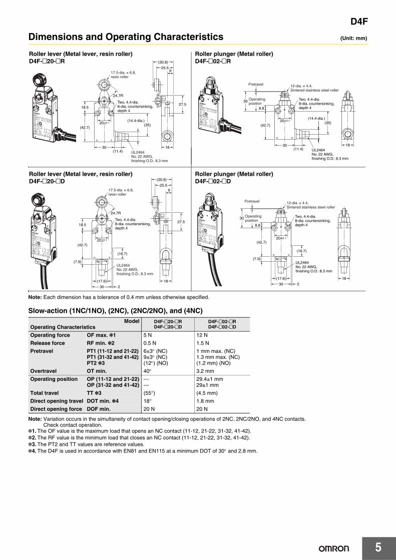
Dimensions and Operating Characteristics (Unit: mm)
Note: Each dimension has a tolerance of 0.4 mm unless otherwise specified.
Slow-action (1NC/1NO), (2NC), (2NC/2NO), and (4NC)
Note: Variation occurs in the simultaneity of contact opening/closing operations of 2NC, 2NC/2NO, and 4NC contacts. Check contact operation.
*1. The OF value is the maximum load that opens an NC contact (11-12, 21-22, 31-32, 41-42).*2. The RF value is the minimum load that closes an NC contact (11-12, 21-22, 31-32, 41-42).*3. The PT2 and TT values are reference values.*4. The D4F is used in accordance with EN81 and EN115 at a minimum DOT of 30° and 2.8 mm.
ModelOperating Characteristics
D4F-@20-@RD4F-@20-@D
D4F-@02-@RD4F-@02-@D
Operating force OF max. *1 5 N 12 N
Release force RF min. *2 0.5 N 1.5 N
Pretravel PT1 (11-12 and 21-22)PT1 (31-32 and 41-42)PT2 *3
6±3° (NC)9±3° (NC)(12°) (NO)
1 mm max. (NC)1.3 mm max. (NC)(1.2 mm) (NO)
Overtravel OT min. 40° 3.2 mm
Operating position OP (11-12 and 21-22)OP (31-32 and 41-42)
------
29.4±1 mm29±1 mm
Total travel TT *3 (55°) (4.5 mm)
Direct opening travel DOT min. *4 18° 1.8 mm
Direct opening force DOF min. 20 N 20 N
9
27.5
18
(30.8)
25.5
24.7R
Two, 4.4-dia. 8-dia. countersinking, depth 4
18.5
(42.7)(35)
30
20±0.1
(11.4)
(14.4-dia.)
17.5-dia. × 6.8, resin roller
UL2464 No. 22 AWG, finishing O.D.: 8.3 mm
18
8.8
30 Operatingposition
Pretravel
(42.7)20±0.1
UL2464 No. 22 AWG, finishing O.D.: 8.3 mm
Two, 4.4-dia. 8-dia. countersinking, depth 4
(11.4)30
(35)(14.4-dia.)
12-dia. × 4.4, Sintered stainless steel roller
27.5
18
UL2464 No. 22 AWG, finishing O.D.: 8.3 mm
17.5-dia. × 6.8, resin roller
24.7R
18.5
(16.7)
(42.7)
(7.9)
30
(17.6)
2
20±0.1
Two, 4.4-dia. 8-dia. countersinking, depth 4
(30.8)
25.59
18
UL2464 No. 22 AWG, finishing O.D.: 8.3 mm
12-dia. × 4.4, Sintered stainless steel roller
8.8
30 Operatingposition
Pretravel
(42.7)
(7.9)
30 2
20±0.1
Two, 4.4-dia. 8-dia. countersinking, depth 4
(17.6)
(16.7)
Roller lever (Metal lever, resin roller)D4F-@20-@R
Roller lever (Metal lever, resin roller)D4F-@20-@D
Roller plunger (Metal roller)D4F-@02-@D
Roller plunger (Metal roller)D4F-@02-@R
6
D4F
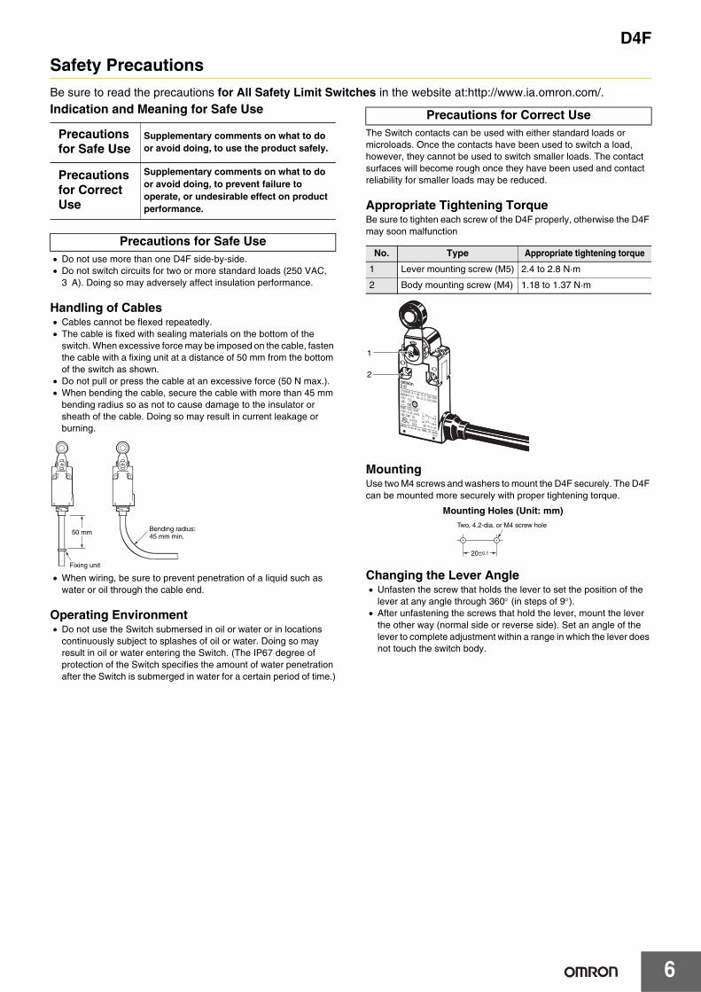
Safety Precautions
Be sure to read the precautions for All Safety Limit Switches in the website at:http://www.ia.omron.com/.Indication and Meaning for Safe Use
• Do not use more than one D4F side-by-side. • Do not switch circuits for two or more standard loads (250 VAC,
3 A). Doing so may adversely affect insulation performance.
Handling of Cables• Cables cannot be flexed repeatedly.• The cable is fixed with sealing materials on the bottom of the
switch. When excessive force may be imposed on the cable, fasten the cable with a fixing unit at a distance of 50 mm from the bottom of the switch as shown.
• Do not pull or press the cable at an excessive force (50 N max.).• When bending the cable, secure the cable with more than 45 mm
bending radius so as not to cause damage to the insulator or sheath of the cable. Doing so may result in current leakage or burning.
• When wiring, be sure to prevent penetration of a liquid such as water or oil through the cable end.
Operating Environment• Do not use the Switch submersed in oil or water or in locations
continuously subject to splashes of oil or water. Doing so may result in oil or water entering the Switch. (The IP67 degree of protection of the Switch specifies the amount of water penetration after the Switch is submerged in water for a certain period of time.)
The Switch contacts can be used with either standard loads or microloads. Once the contacts have been used to switch a load, however, they cannot be used to switch smaller loads. The contact surfaces will become rough once they have been used and contact reliability for smaller loads may be reduced.
Appropriate Tightening TorqueBe sure to tighten each screw of the D4F properly, otherwise the D4F may soon malfunction
.
MountingUse two M4 screws and washers to mount the D4F securely. The D4F can be mounted more securely with proper tightening torque.
Changing the Lever Angle• Unfasten the screw that holds the lever to set the position of the
lever at any angle through 360° (in steps of 9°).• After unfastening the screws that hold the lever, mount the lever
the other way (normal side or reverse side). Set an angle of the lever to complete adjustment within a range in which the lever does not touch the switch body.
Precautions for Safe Use
Supplementary comments on what to do or avoid doing, to use the product safely.
Precautions for Correct Use
Supplementary comments on what to do or avoid doing, to prevent failure to operate, or undesirable effect on product performance.
Precautions for Safe Use
50 mm
Fixing unit
Bending radius:45 mm min.
Precautions for Correct Use
No. Type Appropriate tightening torque
1 Lever mounting screw (M5) 2.4 to 2.8 N·m
2 Body mounting screw (M4) 1.18 to 1.37 N·m
1
2
20±0.1
Two, 4.2-dia. or M4 screw hole
Mounting Holes (Unit: mm)
D4F
7
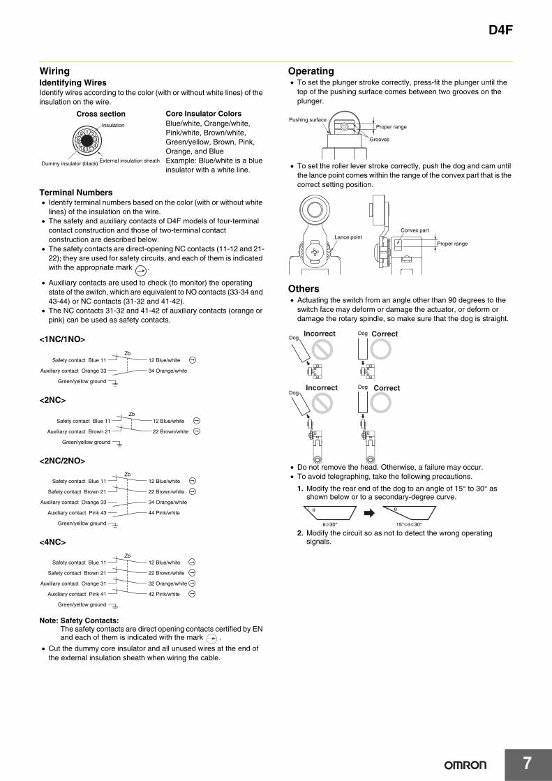
WiringIdentifying WiresIdentify wires according to the color (with or without white lines) of the insulation on the wire.
Terminal Numbers• Identify terminal numbers based on the color (with or without white
lines) of the insulation on the wire.• The safety and auxiliary contacts of D4F models of four-terminal
contact construction and those of two-terminal contact construction are described below.
• The safety contacts are direct-opening NC contacts (11-12 and 21-22); they are used for safety circuits, and each of them is indicated with the appropriate mark .
• Auxiliary contacts are used to check (to monitor) the operating state of the switch, which are equivalent to NO contacts (33-34 and 43-44) or NC contacts (31-32 and 41-42).
• The NC contacts 31-32 and 41-42 of auxiliary contacts (orange or pink) can be used as safety contacts.
<1NC/1NO>
<2NC>
<2NC/2NO>
<4NC>
Note: Safety Contacts:The safety contacts are direct opening contacts certified by EN and each of them is indicated with the mark .
• Cut the dummy core insulator and all unused wires at the end of the external insulation sheath when wiring the cable.
Operating• To set the plunger stroke correctly, press-fit the plunger until the
top of the pushing surface comes between two grooves on the plunger.
• To set the roller lever stroke correctly, push the dog and cam until the lance point comes within the range of the convex part that is the correct setting position.
Others• Actuating the switch from an angle other than 90 degrees to the
switch face may deform or damage the actuator, or deform or damage the rotary spindle, so make sure that the dog is straight.
• Do not remove the head. Otherwise, a failure may occur.• To avoid telegraphing, take the following precautions.
1. Modify the rear end of the dog to an angle of 15° to 30° as shown below or to a secondary-degree curve.
2. Modify the circuit so as not to detect the wrong operating signals.
19
48 3
567
2
Insulation
External insulation sheathDummy insulator (black)
Cross section Core Insulator ColorsBlue/white, Orange/white, Pink/white, Brown/white, Green/yellow, Brown, Pink, Orange, and BlueExample: Blue/white is a blue insulator with a white line.
ZbSafety contact Blue 11
Auxiliary contact Orange 33
Green/yellow ground
12 Blue/white
34 Orange/white
Safety contact Blue 11Zb
Auxiliary contact Brown 21
12 Blue/white
22 Brown/white
Green/yellow ground
ZbSafety contact Blue 11
Auxiliary contact Orange 33
Green/yellow ground
12 Blue/white
34 Orange/white
Safety contact Brown 21 22 Brown/white
Auxiliary contact Pink 43 44 Pink/white
ZbSafety contact Blue 11
Safety contact Brown 21
Auxiliary contact Orange 31
Auxiliary contact Pink 41
12 Blue/white
22 Brown/white
32 Orange/white
42 Pink/white
Green/yellow ground
Proper range
Grooves
Pushing surface
Lance pointConvex part
Proper range
DogDog
DogDog
Incorrect Correct
Incorrect Correct
θ≥30°
θ
15°≤θ≤30°
θ
Terms and Conditions of Sale1. Offer; Acceptance. These terms and conditions (these "Terms") are deemed
part of all quotes, agreements, purchase orders, acknowledgments, price lists,catalogs, manuals, brochures and other documents, whether electronic or inwriting, relating to the sale of products or services (collectively, the "Products")by Omron Electronics LLC and its subsidiary companies (“Omron”). Omronobjects to any terms or conditions proposed in Buyer’s purchase order or otherdocuments which are inconsistent with, or in addition to, these Terms.
2. Prices; Payment Terms. All prices stated are current, subject to change with-out notice by Omron. Omron reserves the right to increase or decrease priceson any unshipped portions of outstanding orders. Payments for Products aredue net 30 days unless otherwise stated in the invoice.
3. Discounts. Cash discounts, if any, will apply only on the net amount of invoicessent to Buyer after deducting transportation charges, taxes and duties, and willbe allowed only if (i) the invoice is paid according to Omron’s payment termsand (ii) Buyer has no past due amounts.
4. Interest. Omron, at its option, may charge Buyer 1-1/2% interest per month orthe maximum legal rate, whichever is less, on any balance not paid within thestated terms.
5. Orders. Omron will accept no order less than $200 net billing. 6. Governmental Approvals. Buyer shall be responsible for, and shall bear all
costs involved in, obtaining any government approvals required for the impor-tation or sale of the Products.
7. Taxes. All taxes, duties and other governmental charges (other than generalreal property and income taxes), including any interest or penalties thereon,imposed directly or indirectly on Omron or required to be collected directly orindirectly by Omron for the manufacture, production, sale, delivery, importa-tion, consumption or use of the Products sold hereunder (including customsduties and sales, excise, use, turnover and license taxes) shall be charged toand remitted by Buyer to Omron.
8. Financial. If the financial position of Buyer at any time becomes unsatisfactoryto Omron, Omron reserves the right to stop shipments or require satisfactorysecurity or payment in advance. If Buyer fails to make payment or otherwisecomply with these Terms or any related agreement, Omron may (without liabil-ity and in addition to other remedies) cancel any unshipped portion of Prod-ucts sold hereunder and stop any Products in transit until Buyer pays allamounts, including amounts payable hereunder, whether or not then due,which are owing to it by Buyer. Buyer shall in any event remain liable for allunpaid accounts.
9. Cancellation; Etc. Orders are not subject to rescheduling or cancellationunless Buyer indemnifies Omron against all related costs or expenses.
10. Force Majeure. Omron shall not be liable for any delay or failure in deliveryresulting from causes beyond its control, including earthquakes, fires, floods,strikes or other labor disputes, shortage of labor or materials, accidents tomachinery, acts of sabotage, riots, delay in or lack of transportation or therequirements of any government authority.
11. Shipping; Delivery. Unless otherwise expressly agreed in writing by Omron:a. Shipments shall be by a carrier selected by Omron; Omron will not drop ship
except in “break down” situations.b. Such carrier shall act as the agent of Buyer and delivery to such carrier shall
constitute delivery to Buyer;c. All sales and shipments of Products shall be FOB shipping point (unless oth-
erwise stated in writing by Omron), at which point title and risk of loss shallpass from Omron to Buyer; provided that Omron shall retain a security inter-est in the Products until the full purchase price is paid;
d. Delivery and shipping dates are estimates only; ande. Omron will package Products as it deems proper for protection against nor-
mal handling and extra charges apply to special conditions.12. Claims. Any claim by Buyer against Omron for shortage or damage to the
Products occurring before delivery to the carrier must be presented in writingto Omron within 30 days of receipt of shipment and include the original trans-portation bill signed by the carrier noting that the carrier received the Productsfrom Omron in the condition claimed.
13. Warranties. (a) Exclusive Warranty. Omron’s exclusive warranty is that theProducts will be free from defects in materials and workmanship for a period oftwelve months from the date of sale by Omron (or such other period expressedin writing by Omron). Omron disclaims all other warranties, express or implied.(b) Limitations. OMRON MAKES NO WARRANTY OR REPRESENTATION,EXPRESS OR IMPLIED, ABOUT NON-INFRINGEMENT, MERCHANTABIL-
ITY OR FITNESS FOR A PARTICULAR PURPOSE OF THE PRODUCTS.BUYER ACKNOWLEDGES THAT IT ALONE HAS DETERMINED THAT THEPRODUCTS WILL SUITABLY MEET THE REQUIREMENTS OF THEIRINTENDED USE. Omron further disclaims all warranties and responsibility ofany type for claims or expenses based on infringement by the Products or oth-erwise of any intellectual property right. (c) Buyer Remedy. Omron’s sole obli-gation hereunder shall be, at Omron’s election, to (i) replace (in the formoriginally shipped with Buyer responsible for labor charges for removal orreplacement thereof) the non-complying Product, (ii) repair the non-complyingProduct, or (iii) repay or credit Buyer an amount equal to the purchase price ofthe non-complying Product; provided that in no event shall Omron be responsi-ble for warranty, repair, indemnity or any other claims or expenses regardingthe Products unless Omron’s analysis confirms that the Products were prop-erly handled, stored, installed and maintained and not subject to contamina-tion, abuse, misuse or inappropriate modification. Return of any Products byBuyer must be approved in writing by Omron before shipment. Omron Compa-nies shall not be liable for the suitability or unsuitability or the results from theuse of Products in combination with any electrical or electronic components,circuits, system assemblies or any other materials or substances or environ-ments. Any advice, recommendations or information given orally or in writing,are not to be construed as an amendment or addition to the above warranty.See http://www.omron247.com or contact your Omron representative for pub-lished information.
14. Limitation on Liability; Etc. OMRON COMPANIES SHALL NOT BE LIABLEFOR SPECIAL, INDIRECT, INCIDENTAL, OR CONSEQUENTIAL DAMAGES,LOSS OF PROFITS OR PRODUCTION OR COMMERCIAL LOSS IN ANYWAY CONNECTED WITH THE PRODUCTS, WHETHER SUCH CLAIM ISBASED IN CONTRACT, WARRANTY, NEGLIGENCE OR STRICT LIABILITY.Further, in no event shall liability of Omron Companies exceed the individualprice of the Product on which liability is asserted.
15. Indemnities. Buyer shall indemnify and hold harmless Omron Companies andtheir employees from and against all liabilities, losses, claims, costs andexpenses (including attorney's fees and expenses) related to any claim, inves-tigation, litigation or proceeding (whether or not Omron is a party) which arisesor is alleged to arise from Buyer's acts or omissions under these Terms or inany way with respect to the Products. Without limiting the foregoing, Buyer (atits own expense) shall indemnify and hold harmless Omron and defend or set-tle any action brought against such Companies to the extent based on a claimthat any Product made to Buyer specifications infringed intellectual propertyrights of another party.
16. Property; Confidentiality. Any intellectual property in the Products is the exclu-sive property of Omron Companies and Buyer shall not attempt to duplicate itin any way without the written permission of Omron. Notwithstanding anycharges to Buyer for engineering or tooling, all engineering and tooling shallremain the exclusive property of Omron. All information and materials suppliedby Omron to Buyer relating to the Products are confidential and proprietary,and Buyer shall limit distribution thereof to its trusted employees and strictlyprevent disclosure to any third party.
17. Export Controls. Buyer shall comply with all applicable laws, regulations andlicenses regarding (i) export of products or information; (iii) sale of products to“forbidden” or other proscribed persons; and (ii) disclosure to non-citizens ofregulated technology or information.
18. Miscellaneous. (a) Waiver. No failure or delay by Omron in exercising any rightand no course of dealing between Buyer and Omron shall operate as a waiverof rights by Omron. (b) Assignment. Buyer may not assign its rights hereunderwithout Omron's written consent. (c) Law. These Terms are governed by thelaw of the jurisdiction of the home office of the Omron company from whichBuyer is purchasing the Products (without regard to conflict of law princi-ples). (d) Amendment. These Terms constitute the entire agreement betweenBuyer and Omron relating to the Products, and no provision may be changedor waived unless in writing signed by the parties. (e) Severability. If any provi-sion hereof is rendered ineffective or invalid, such provision shall not invalidateany other provision. (f) Setoff. Buyer shall have no right to set off any amountsagainst the amount owing in respect of this invoice. (g) Definitions. As usedherein, “including” means “including without limitation”; and “Omron Compa-nies” (or similar words) mean Omron Corporation and any direct or indirectsubsidiary or affiliate thereof.
Certain Precautions on Specifications and Use1. Suitability of Use. Omron Companies shall not be responsible for conformity
with any standards, codes or regulations which apply to the combination of theProduct in the Buyer’s application or use of the Product. At Buyer’s request,Omron will provide applicable third party certification documents identifyingratings and limitations of use which apply to the Product. This information byitself is not sufficient for a complete determination of the suitability of the Prod-uct in combination with the end product, machine, system, or other applicationor use. Buyer shall be solely responsible for determining appropriateness ofthe particular Product with respect to Buyer’s application, product or system.Buyer shall take application responsibility in all cases but the following is anon-exhaustive list of applications for which particular attention must be given:(i) Outdoor use, uses involving potential chemical contamination or electricalinterference, or conditions or uses not described in this document.(ii) Use in consumer products or any use in significant quantities. (iii) Energy control systems, combustion systems, railroad systems, aviationsystems, medical equipment, amusement machines, vehicles, safety equip-ment, and installations subject to separate industry or government regulations. (iv) Systems, machines and equipment that could present a risk to life or prop-erty. Please know and observe all prohibitions of use applicable to this Prod-uct. NEVER USE THE PRODUCT FOR AN APPLICATION INVOLVING SERIOUSRISK TO LIFE OR PROPERTY OR IN LARGE QUANTITIES WITHOUTENSURING THAT THE SYSTEM AS A WHOLE HAS BEEN DESIGNED TO
ADDRESS THE RISKS, AND THAT THE OMRON’S PRODUCT IS PROP-ERLY RATED AND INSTALLED FOR THE INTENDED USE WITHIN THEOVERALL EQUIPMENT OR SYSTEM.
2. Programmable Products. Omron Companies shall not be responsible for theuser’s programming of a programmable Product, or any consequence thereof.
3. Performance Data. Data presented in Omron Company websites, catalogsand other materials is provided as a guide for the user in determining suitabil-ity and does not constitute a warranty. It may represent the result of Omron’stest conditions, and the user must correlate it to actual application require-ments. Actual performance is subject to the Omron’s Warranty and Limitationsof Liability.
4. Change in Specifications. Product specifications and accessories may bechanged at any time based on improvements and other reasons. It is our prac-tice to change part numbers when published ratings or features are changed,or when significant construction changes are made. However, some specifica-tions of the Product may be changed without any notice. When in doubt, spe-cial part numbers may be assigned to fix or establish key specifications foryour application. Please consult with your Omron’s representative at any timeto confirm actual specifications of purchased Product.
5. Errors and Omissions. Information presented by Omron Companies has beenchecked and is believed to be accurate; however, no responsibility is assumedfor clerical, typographical or proofreading errors or omissions.
OMRON CANADA, INC. • HEAD OFFICEToronto, ON, Canada • 416.286.6465 • 866.986.6766 • www.omron247.com
OMRON ELECTRONICS DE MEXICO • HEAD OFFICEMéxico DF • 52.55.59.01.43.00 • 01-800-226-6766 • [email protected]
OMRON ELECTRONICS DE MEXICO • SALES OFFICEApodaca, N.L. • 52.81.11.56.99.20 • 01-800-226-6766 • [email protected]
OMRON ELETRÔNICA DO BRASIL LTDA • HEAD OFFICESão Paulo, SP, Brasil • 55.11.2101.6300 • www.omron.com.br
OMRON ARGENTINA • SALES OFFICECono Sur • 54.11.4783.5300
OMRON CHILE • SALES OFFICESantiago • 56.9.9917.3920
OTHER OMRON LATIN AMERICA SALES54.11.4783.5300
Authorized Distributor:
C73I-E-02 04/15 Note: Specifications are subject to change. © 2015 Omron Electronics LLC Printed in U.S.A.
Printed on recycled paper.
Automation Control Systems• Machine Automation Controllers (MAC) • Programmable Controllers (PLC) • Operator interfaces (HMI) • Distributed I/O • Software
Drives & Motion Controls • Servo & AC Drives • Motion Controllers & Encoders
Temperature & Process Controllers • Single and Multi-loop Controllers
Sensors & Vision• Proximity Sensors • Photoelectric Sensors • Fiber-Optic Sensors• Amplified Photomicrosensors • Measurement Sensors• Ultrasonic Sensors • Vision Sensors
Industrial Components • RFID/Code Readers • Relays • Pushbuttons & Indicators• Limit and Basic Switches • Timers • Counters • Metering Devices • Power Supplies
Safety • Laser Scanners • Safety Mats • Edges and Bumpers • Programmable Safety
Controllers • Light Curtains • Safety Relays • Safety Interlock Switches
OMRON AUTOMATION AND SAFETY • THE AMERICAS HEADQUARTERS • Chicago, IL USA • 847.843.7900 • 800.556.6766 • www.omron247.com
OMRON EUROPE B.V. • Wegalaan 67-69, NL-2132 JD, Hoofddorp, The Netherlands. • +31 (0) 23 568 13 00 • www.industrial.omron.eu