d4.3 - validation report
TRANSCRIPT
This project has received funding from the European Union’s Horizon 2020 research and innovation programme under Grant Agreement No 777561 Call identifier: H2020-S2RJU-2017 | Topic: S2R-OC-IP2-01-2017 – Operational conditions of the signalling and automation systems; signalling system
hazard analysis and GNSS SIS characterization along with Formal Method application in railway field
D4.3 – Validation Report
Deliverable ID D4.3
Deliverable Title Validation Report
Work Package WP4
Dissemination Level PUBLIC
Version 1.4
Date 06/12/2019
Status Final
Lead Editor SIRTI
Main Contributors CNR
Published by the ASTRAIL Consortium
Ref. Ares(2019)7719400 - 16/12/2019

Satellite-based Signalling and Automation Systems on Railways along with formal Method ad Moving Block Validation
Deliverable nr.
Deliverable Title
Version
D4.3
Validation Report
1.4 - 06/12/2019
Page 2 of 70
Document History
Version Date Author(s) Description
0.0 2019-05-24 SIRTI First Draft with TOC
0.1 2019-06-07 CNR Changes in structure and tasks distribution
0.2 2019-06-26 CNR Section 3 “Moving Block and ATO Modelling” added
0.3 2019-06-27 CNR Section 3 “Moving Block and ATO Modelling” updated
0.4 2019-07-02 CNR, SIRTI Section 5 “Quantitative Verification” updated
0.5 2019-07-10 CNR Section 2 “Validation of the Process” updated
0.6 2019-07-24 CNR Section 4 “Qualitative verification” updated
0.7 2019-08-06 CNR Section 4 “Qualitative verification” updated
0.8 2019-08-09 SIRTI Annex A added
0.9 2019-08-14 CNR Section 4 “Qualitative verification” updated
1.0 2019-08-22 CNR Section 5 “Qualitative Verification” removed, “Introduction” added, Section 2, 3, 4 Updated
1.1 2019-08-26 CNR Added Conclusion section
1.2 2019-08-27 SIRTI Updated Conclusion section, typo review
1.3 2019-08-30 SIRTI, CNR Annex A updated. Final release.
1.4 2019-12-06 SIRTI, CNR Acronyms table updated.
Legal Notice
The information in this document is subject to change without notice. The Members of the ASTRail Consortium make no warranty of any kind with regard to this document, including, but not limited to, the implied warranties of merchantability and fitness for a particular purpose. The Members of the ASTRail Consortium shall not be held liable for errors contained herein or direct, indirect, special, incidental or consequential damages in connection with the furnishing, performance, or use of this material. The Shift2Rail JU cannot be held liable for any damage caused by the Members of the ASTRail Consortium or to third parties as a consequence of implementing this Grant Agreement No 777561, including for gross negligence. The Shift2Rail JU cannot be held liable for any damage caused by any of the beneficiaries or third parties involved in this action, as a consequence of implementing this Grant Agreement No 777561. The information included in this report reflects only the authors' view and the Shift2Rail JU is not responsible for any use that may be made of such information.
Satellite-based Signalling and Automation Systems on Railways along with formal Method ad Moving Block Validation
Deliverable nr.
Deliverable Title
Version
D4.3
Validation Report
1.4 - 06/12/2019
Page 3 of 70
Table of Contents
Document History ...................................................................................................................................................................................... 2
Legal Notice .................................................................................................................................................................................................. 2
Table of Contents ....................................................................................................................................................................................... 3
1 Introduction ........................................................................................................................................................................................ 5
1.1 Purpose and Scope ................................................................................................................................................................ 5
1.2 Executive Summary................................................................................................................................................................ 5
1.3 Related documents................................................................................................................................................................ 7
2 Validation of the Process............................................................................................................................................................... 8
2.1 Formal methods selection .................................................................................................................................................. 8
2.1.1 Main Output from Previous Deliverables ................................................................................................................ 8
2.1.2 Choice of Formal Methods based on the Development Context .................................................................. 8
2.2 Formal Methods Application Process ............................................................................................................................ 9
2.2.1 Requirements Elicitation and Simulation ............................................................................................................... 10
2.2.2 Mapping to Formal Languages ................................................................................................................................. 11
2.2.3 Formal Verification ......................................................................................................................................................... 11
3 Moving Block and ATO modelling .......................................................................................................................................... 12
3.1 Simulink and Stateflow Languages ............................................................................................................................... 12
3.2 Moving Block ......................................................................................................................................................................... 14
3.2.1 Moving Block Overview ................................................................................................................................................ 14
3.2.2 Moving-block Model Architecture ........................................................................................................................... 15
3.2.3 Behaviour of the Moving-block System: OBU Component............................................................................ 17
3.2.4 Behaviour of the Moving-block System: LU Component................................................................................ 20
3.2.5 Behaviour of the Moving-block System: RBC Component ............................................................................. 20
3.2.6 Behaviour of the Moving-block System: Train Component ........................................................................... 21
3.3 ATO ............................................................................................................................................................................................ 22
3.3.1 ATO Overview ................................................................................................................................................................... 22
3.3.2 ATO Model Architecture .............................................................................................................................................. 23
3.3.3 ATO Behaviour: Operating Modes ........................................................................................................................... 24
3.3.4 ATO Behaviour: Speed Control and Train.............................................................................................................. 26
3.4 Integrated Model ................................................................................................................................................................. 30
3.4.1 Integrated Model Architecture .................................................................................................................................. 30
3.4.2 Integrated Model Behaviour ....................................................................................................................................... 32
3.5 Requirements Elicitation and Simulation with Simulink: Observations .......................................................... 34
4 Qualitative verification ................................................................................................................................................................. 36
4.1 The UML system description ........................................................................................................................................... 36
4.1.1 Briefs on the used UML statecharts notation ...................................................................................................... 36
4.1.2 Some differences w.r.t Simulink/Stateflow modelling ...................................................................................... 37
4.1.3 Introduction to the Moving Block and ATO UML modelling ........................................................................ 38
4.1.4 OBU....................................................................................................................................................................................... 38
4.1.5 RBC........................................................................................................................................................................................ 41
Satellite-based Signalling and Automation Systems on Railways along with formal Method ad Moving Block Validation
Deliverable nr.
Deliverable Title
Version
D4.3
Validation Report
1.4 - 06/12/2019
Page 4 of 70
4.1.6 ATO ....................................................................................................................................................................................... 44
4.2 The EventB/ProB modelling ............................................................................................................................................. 46
4.3 The EventB/ProB verification ........................................................................................................................................... 50
4.3.1 Moving Block verification ............................................................................................................................................ 51
4.3.2 ATO verification ............................................................................................................................................................... 55
4.3.3 Integrated Moving Block and ATO verification ................................................................................................... 57
4.4 Observations .......................................................................................................................................................................... 59
4.4.1 Correctness of the system design ............................................................................................................................ 59
4.4.2 Correctness of the ProB translation ......................................................................................................................... 59
4.4.3 Correctness of the LTL formulas................................................................................................................................ 60
4.4.4 Correctness of the ProB tool ...................................................................................................................................... 60
4.4.5 Current limits of our approach .................................................................................................................................. 60
5 Conclusions ....................................................................................................................................................................................... 62
Acronyms ..................................................................................................................................................................................................... 64
List of figures .............................................................................................................................................................................................. 65
Annex A – System Requirements ....................................................................................................................................................... 66
References ................................................................................................................................................................................................... 70

Satellite-based Signalling and Automation Systems on Railways along with formal Method ad Moving Block Validation
Deliverable nr.
Deliverable Title
Version
D4.3
Validation Report
1.4 - 06/12/2019
Page 5 of 70
1 Introduction
1.1 Purpose and Scope
Formal methods are mathematically-based techniques to support the development of software intensive systems [23][22]. Normally, formal methods oriented to design and verification of systems include (i) a modelling language, which is used to model a system, and (ii) a verification strategy, which is used to verify properties on the system. Formal methods are usually associated to formal tools, which can provide textual or visual editors to create a model of the system, as well as automated verification capabilities. Formal methods have been largely applied in industrial projects, especially in the safety-critical market, including railways [24]. However, it cannot yet be said that a single mature technology has emerged. The Work Package 4 (WP4) of the ASTRail project aims to identify, based on an analysis of the state-of-the-art and on concrete trials, the candidate set of formal and semi-formal methods that appear as the most adequate to be used in the railway context. In the following, when we will use the general term “formal method”, we will implicitly include also semi-formal methods, i.e. those methods that use languages for which the semantics is not formally defined but depends on their execution engine. Since formal methods are normally associated with tools, we will also use the terms formal methods and formal tools interchangeably. To address the goal of identifying the most adequate formal methods, WP4 is structured into four tasks (T4.4, in bold, is the focus on the current deliverable):
• Task 4.1 - Benchmarking: this task aims at studying the state-of-the-art and state of the practice of formal and semi-formal methods, by gathering knowledge from the literature and railway practitioners.
• Task 4.2 - Ranking: this task aims at providing a ranking matrix to support the selection of the most adequate formal methods to be used in a certain development context.
• Task 4.3 - Trial Application: this task aims at experimenting the usage of a set of selected formal methods through the modelling of the moving-block system, from Task 2.1.
• Task 4.4 - Validation: this task aims at validating the usage of the selected formal methods by integrating the moving-block model with the automated driving technologies from Task 3.3.
The current deliverable D4.3 Validation Report is the output of Task 4.4 – Validation. The results of Task 4.1-2 and 4.3 have been reported in D4.1 [RD.1] and D4.2 [RD.5] respectively.
1.2 Executive Summary
The description of Task 4.4 - Validation Report is as follows:
In order to validate the choices and techniques consolidated in task T4.3 we will address, in collaboration with the other partners of the project, the modelling of the integration of Moving Block with Automated Driving Technologies (from T.3.3), providing for each considered item a full model that will represent a rigorous and verifiable definition of functional, interoperability and dependability requirements.
In Task 4.3 a series of formal techniques were evaluated and a main output of the task was that a combination of techniques is required to address different needs and phases of the railway process. Combinations of techniques should be chosen based on the context. Therefore, validating choices and techniques, as discussed in the proposal, implies defining and assessing a formal development process that is appropriate for the current context of development. Hence, this deliverable is concerned with the validation of a proposed formal process, by means of modelling and verification, applied to Moving Block with Automated Driving Technologies. In the context of the ASTRail project, both Moving Block and Automated Driving Technologies (referred in the following as Automated Train Operation or ATO) can be considered as being at the concept phase of development. Indeed, preliminary requirements were defined for the Moving Block (see [RD.5]), and only high-level functions were defined for the ATO in Task 3.3 (see [RD.4]).

Satellite-based Signalling and Automation Systems on Railways along with formal Method ad Moving Block Validation
Deliverable nr.
Deliverable Title
Version
D4.3
Validation Report
1.4 - 06/12/2019
Page 6 of 70
For the concept phase of the development, in which requirements need to be elicited and consolidated, the proposed process supported by formal methods foresees the following phases:
• Requirements Elicitation and Simulation: for which Simulink-Stateflow was selected as appropriate tool to provide a rigorous, complete modelling of the integration of the Moving Block with ATO, and to produce a requirements specification for the integrated system;
• Mapping to Formal Languages: for which UML was chosen as intermediate language towards a formalisation into Event-B;
• Formal Verification: for which ProB was chosen as formal tool to verify the requirements against the Event B model.
The proposed process was applied to the modelling and verification of the Moving Block with ATO. First, two separate Simulink-Stateflow models were developed for the Moving Block and the ATO, based on a set of preliminary requirements. The requirements were then extended and consolidated based on the simulation, an integrated model was developed and a final integrated requirements specification was produced. The models are reported at [25]. Instead, the requirements are reported in the Annex A – System Requirements. The model and the requirements were used as input to define a UML model oriented to have a clear, established specification that could be used as a reference for translation into formal languages. The UML model was translated into EventB, the formal input language of ProB. The graphical UML model is reported in this deliverable, while the ProB model is available at [25]. Given the EventB model that integrates Moving Block and ATO, formal verification activities were carried out with the ProB tool. Specifically, part of the requirements reported in the Annex A – System Requirements were mapped to Linear Temporal Logic (LTL) formulae, and model checking was performed with ProB. The implementation of the process and its application to the Moving Block with ATO has showcased strong points and weaknesses of the applied strategy. Specifically, the main strengths are:
1. Modelling and simulating with Simulink-Stateflow enables the identification of incomplete, inconsistent, or too generic requirements, as it forces the modeller to take implementation choices, and allows the user to observe the behaviour of the system and interact with it.
2. Graphical models are easy to understand by domain experts, and reading Simulink-Stateflow models required limited guidance, therefore making the language suitable for interaction between formal methods experts and railway domain experts.
3. The UML modelling activity enables the abstraction from concrete choices required by the Simulink-Stateflow platform, and, in particular, allows the modeller to observe nondeterministic behaviour.
4. The translation of the UML model into Event B enables the further activities of formal verification, but allows also the modeller to identify mistakes in the design.
5. The translation of the requirements into temporal logic formulas to be verified again allows the identification of mistakes in the model or in the requirements.
6. The formal verification activity can be performed with acceptable, though not negligible, time for most of the requirements.
Instead, observed weaknesses to consider are:
1. The modelling and translation processes are time consuming with respect to defining a requirements document in natural language.
2. The produced models, although consolidated and revised multiple times throughout the process, are not guaranteed to be stable, as new requirements may emerge during further refinements.
3. The formal methods experts must make choices both in the modelling phase and in the translation activities. These choices, concerning for example the decision of modelling subsets of the system to enable formal verification, require the expertise in formal methods and cannot be automatically performed with the selected tools.
4. Depending on their nature, part of the requirements could be not formally verified, and require other means to assess them.
5. The whole proposed process is not entirely supported by tools. In particular, the translation activities are performed manually.
Satellite-based Signalling and Automation Systems on Railways along with formal Method ad Moving Block Validation
Deliverable nr.
Deliverable Title
Version
D4.3
Validation Report
1.4 - 06/12/2019
Page 7 of 70
Given these observations, the proposed formal process cannot be considered as a fully automated technique. However, the different steps involved, the different languages used, and the different degree of formality of the different steps enabled the possibility of producing a set of consolidated requirements for the integrated Moving-block and ATO system as well as verifiable specifications of the requirements in the form of formal and semi-formal models. The remainder of the deliverable is structured as follows:
1. In Section 2 we present the overview of how the formal methods choices have been validated within ASTRail;
2. In Section 3 we present the activity of modelling and simulating with Simulink-Stateflow; 3. In Section 4 we present the activities of translation into formal models, through UML and Event B, and
formal verification with ProB; 4. In Section 5, we report conclusion and final remarks.
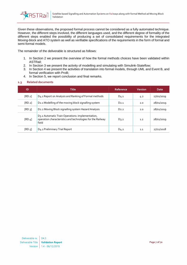
1.3 Related documents
ID Title Reference Version Date
[RD.1] D4.1 Report on Analysis and Ranking of Formal methods D4.1 4.2 17/01/2019
[RD.2] D2.1 Modelling of the moving block signalling system D2.1 2.0 28/01/2019
[RD.3] D2.2 Moving Block signalling system Hazard Analysis D2.2 2.0 28/01/2019
[RD.4] D3.2 Automatic Train Operations: implementation, operation characteristics and technologies for the Railway field
D3.2 1.2 28/01/2019
[RD.5] D4.2 Preliminary Trial Report D4.2 1.1 27/11/2018

Satellite-based Signalling and Automation Systems on Railways along with formal Method ad Moving Block Validation
Deliverable nr.
Deliverable Title
Version
D4.3
Validation Report
1.4 - 06/12/2019
Page 8 of 70
2 Validation of the Process
This section describes the methodology followed to validate the proposed process to select and adopt formal methods in the railway context. Specifically, we first explain how we selected a subset of the available formal methods, and how we have used them for different purposes, namely requirements elicitation and simulation, and formal verification. It is worth highlighting that the process outlined is applied in the concept phase of the development process, in which early requirements are defined and preliminarily validated. It is outside the scope of this deliverable to present a full formal process from early requirements to implementation. Our goal is instead to highlight how the features of diverse tools can be exploited for different purposes.
2.1 Formal methods selection
In this section we present how we have leveraged the information from the previous deliverables, namely D4.1 and D4.2, to select the appropriate formal methods to use in our context. Specifically, we justify why we have chosen Simulink-Stateflow for requirements elicitation and consolidation, and why we have selected UML as intermediate representation and ProB for formal verification. In the following, we first outline the most relevant information from previous deliverables, and then we motivate our choices.
2.1.1 Main Output from Previous Deliverables
In this section, we list the main output from the previous deliverable that we considered to support the selection of formal methods for our specific context. In D4.1, we performed a literature survey on formal methods applications to railway problems, complemented with a review of projects, a questionnaire with practitioners and a preliminary tool evaluation. One of the main output from D4.1, also published in [20] and [21], is the dominance of the B method and associated supporting tools (Rodin environment, Atelier B, ProB) in the railway context. In D4.2, we performed a tool trial, by modelling a preliminary specification of the moving-block system with fourteen formal tools, selected based on the survey from D4.1. Furthermore, we performed a usability test for the eight selected tools. Despite the dominance of the B method in literature and practice, D4.2 has shown that each method and associated tool is appropriate for different development contexts. Specifically, one of the main conclusions from D4.2 was as follows:
• Simulink and SCADE are appropriate for both early prototyping and detailed design towards code generation, other tools need to be used when aiming at formal verification.
• UMC is appropriate for initial prototyping, when one wants to adopt a design based on UML state machines to facilitate communication with different stakeholders, but wants also verification capabilities as the ones provided by UMC.
• Uppaal is appropriate when one needs to focus on the verification quantitative, real-time properties and probabilistic aspects.
• NuSMV and SPIN are appropriate when the system, or composition of systems, has a large state space, and one needs to verify temporal logic properties.
• Atelier B and ProB are the right choice for top-down development (i.e., from initial design to code) of single systems, and have somewhat complementary verification capabilities, with Atelier B supporting invariants checking, and ProB supporting model checking.
Other tools, although not widely used in railways, such as CADP and FDR4, have been also experimented in the context of the project and demonstrated their appropriateness for the modelling and verification in the context of large scale, systems of systems. Finally, another output from D4.2, concerning usability of formal tools, as evaluated by railway practitioners in the context of the project, is that tools that offer graphical simulation capabilities such as Simulink, SCADE, ProB and Uppaal are considered more usable, and easy to understand by practitioners.
2.1.2 Choice of Formal Methods based on the Development Context
As mentioned, the current context is the concept phase of the development. In this phase, requirements for the moving-block system and the ATO need to be (1) elicited from stakeholders and documentation, (2) preliminary assessed with formal verification.

Satellite-based Signalling and Automation Systems on Railways along with formal Method ad Moving Block Validation
Deliverable nr.
Deliverable Title
Version
D4.3
Validation Report
1.4 - 06/12/2019
Page 9 of 70
Therefore, we have chosen Simulink (and its package for state machines modelling, named Stateflow) as a means to support the requirements elicitation task of this phase. Although also SCADE would have been an appropriate choice according to the conclusions reported above, we selected Simulink since, from our tool usability evaluation presented in D4.2, the tool was considered the most usable by the participants (System Usability (SUS) Score: 76 over 100). Since in the early phase of elicitation it is crucial that all the involved stakeholders, namely formal methods experts and railway experts, understand the language used for modelling, Simulink was considered as a suitable choice for our project. Concerning formal verification of the requirements, i.e., verification of qualitative properties related to conditions and expected actions, we have selected ProB as the main tool given (a) the dominance of this tool in the railway context, as outlined by D4.1, and (b) it evaluation in terms of usability as shown in D4.2 (SUS Score: 62 over 100, ranked third in terms of usability right after Simulink and SCADE).
2.2 Formal Methods Application Process
In this section we provide an overview of the application of the formal process, based on the selected formal methods and tools. The output of the process in terms of models is further detailed in Sect. 3 and 4. Figure 1 outlines the adopted formal process. The starting point of the process is a set of input documents about the systems to be developed (External Documents). Specifically, in our context, we leveraged the preliminary requirements of the moving-block system developed in D4.2, and the requirements for the ATO system available from the Shift2Rail X2Rail-1 deliverable D4.1 - ATO over ETCS GoA2 Specification [26]. These documents were used as a source to draft the first early requirements for the moving-block and ATO systems (Requirements Drafting). The produced requirements, expressed in natural language and complemented with informal models, were then represented and simulated by means of Simulink-Stateflow (Semi-formal Modelling and Simulation with Simulink-Stateflow). This activity allowed to further elicit, refine and improve the drafted requirements towards a stable requirements document. The produced Simulink-Stateflow model together with the produced requirements were used as a starting point for formal verification. To enable verification, the requirements expressed through the model were first represented into an intermediate format, namely UML Statecharts (Semi-formal Modelling with UML Statecharts). The goal was to have an intermediate model expressed in a format from which different, comparable formal models could be potentially derived. We have chosen to use UML Statecharts as UML is the most common language for representation of systems in railways, as shown by the results in D4.1. From the UML Statecharts model, a formal ProB model was derived (Formal Modelling with ProB). Qualitative formal verification was then performed on this model, based on the requirements defined earlier. The verification allows to assess the requirements and possibly improve them (Formal Verification with ProB). The UML model can also be used as a starting point to derive other models, and practice formal methods diversity, by comparing the results obtained with other tools.

Satellite-based Signalling and Automation Systems on Railways along with formal Method ad Moving Block Validation
Deliverable nr.
Deliverable Title
Version
D4.3
Validation Report
1.4 - 06/12/2019
Page 10 of 70
Figure 1 Overview of the adopted formal process
2.2.1 Requirements Elicitation and Simulation
In this section we outline the process followed to provide the models for the moving-block and the ATO, and to define the final set of requirements for the two components, including systems integration elements. Moving-block: the moving-block requirements were preliminarily defined as part of D4.2. During the current task of ASTRail, the preliminary requirements were further refined and simulated by means of Simulink-Stateflow. Specifically, representative formal methods experts from CNR developed the Simulink-Stateflow model based on the requirements reported in D4.2. Whenever a requirement was considered inconsistent, incomplete, or unclear, based on the modelling and simulation activities, reported back the problem to the railway domain experts from SIRTI. The interaction was aided by the graphical models presented to the experts
Satellite-based Signalling and Automation Systems on Railways along with formal Method ad Moving Block Validation
Deliverable nr.
Deliverable Title
Version
D4.3
Validation Report
1.4 - 06/12/2019
Page 11 of 70
from SIRTI, who took care of updating and modifying the original requirements, based on the reported problems. At the end of these iterations, a novel requirements document was produced for the moving-block system. The document is reported in Annex A – System Requirements – Part 1, Moving Block. ATO: the initial ATO requirements come from the Shift2Rail X2Rail-1 deliverable D4.1 - ATO over ETCS GoA2 Specification [26]. Differently from the moving-block requirements, these are very detailed, and a complete model of them was considered out of the scope of the current project. Therefore, in this case, the railway experts from SIRTI selected a subset of the requirements that could be suitable to produce a model to be integrated with the moving-block model. These initial requirements were modelled, simulated and refined with the same approach used for the moving-block system, i.e., by means of multiple iterations and discussion between CNR and SIRTI. The document is reported in Annex A – System Requirements – Part 2, ATO. Integrated System: following the definition of the requirements for moving-block and ATO, an integrated Simulink-Stateflow model was produced by CNR. This model was used as a baseline to define the final requirements concerning the interaction between ATO and moving-block. These final requirements, developed by SIRTI, are reported in Annex A – System Requirements – Part 3, Integrated System.
2.2.2 Mapping to Formal Languages
In this section we outline how the original model and requirements for the Integrated System were mapped into the ProB input language, named ProB, to enable verification. This activity involved modellers from CNR and representative of SIRTI, to adjust the requirements previously produced. For the mapping towards EventB, a first modelling by means of the UML language was performed by CNR. This modelling activity took into account the requirements produced, and reported in Annex A – System Requirements, together with the integrated Simulink model (Annex A – System Requirements – Part 3, Integrated System). The modelling abstracted away from quantitative aspects that were not relevant for the foreseen type of formal verification. After the UML representation, an EventB model was defined as a faithful mapping of the UML model, to enable formal verification. The mapping activity, together with the UML model and EventB model, is reported in Section 4 together with the formal verification activity introduced in the next section. It is worth mentioning that the model produced in UML, and translated into EventB, is not a faithful translation of the original Simulink-Stateflow model. Indeed, the goal of this model is to enable the analysis of relevant requirements aspects, and not to verify the original Simulink-Stateflow design, which was oriented towards the elicitation of the requirements. This opportunistic and non-systematic approach to modelling and verification is considered appropriate for this concept phase, to clarify whether the elicited the requirements are reasonable.
2.2.3 Formal Verification
In this section we outline the process followed verify the components from a quantitative and qualitative point of view. This verification activity was oriented to showcase the process, to demonstrate that the system specification produced, i.e., the requirements and the Simulink-Stateflow model, is verifiable, as originally planned in the DoW. The formal verification was performed by means of the ProB tool. To this end, part of the requirements reported in Annex A – System Requirements were considered and translated into linear temporal logic (LTL) formulas. The translation process, results and comments are reported in Section 4.3.
Satellite-based Signalling and Automation Systems on Railways along with formal Method ad Moving Block Validation
Deliverable nr.
Deliverable Title
Version
D4.3
Validation Report
1.4 - 06/12/2019
Page 12 of 70
3 Moving Block and ATO modelling
In this section we provide a description of the moving block and ATO Simulink models developed, based on the process described in Sect.2.2.1. We first describe some basic principles of the Simulink and Stateflow languages, which are useful to understand the rest of the section. Then, we present each model individually, and we describe the final, integrated model, pinpointing the adjustments needed to complete the integration. At the end of the section, we discuss observations throughout the process of requirements elicitation and simulation.
3.1 Simulink and Stateflow Languages
Simulink is a commercial model based development tool, distributed by Mathworks, that allows the user to graphically draw diagrams of the system modelled in the form of input-output blocks. The blocks can be further refined in the form of hierarchical state machines through the tool Stateflow, included in Simulink. Simulink comes with several packages, also for code generation from the models. For the current models, we used Simulink 2017b. Below, we present some basic concepts about the Simulink and Stateflow languages, useful to interpret the models presented in the following sections. For more details, we refer to the extensive Simulink documentation [2]
Satellite-based Signalling and Automation Systems on Railways along with formal Method ad Moving Block Validation
Deliverable nr.
Deliverable Title
Version
D4.3
Validation Report
1.4 - 06/12/2019
Page 13 of 70
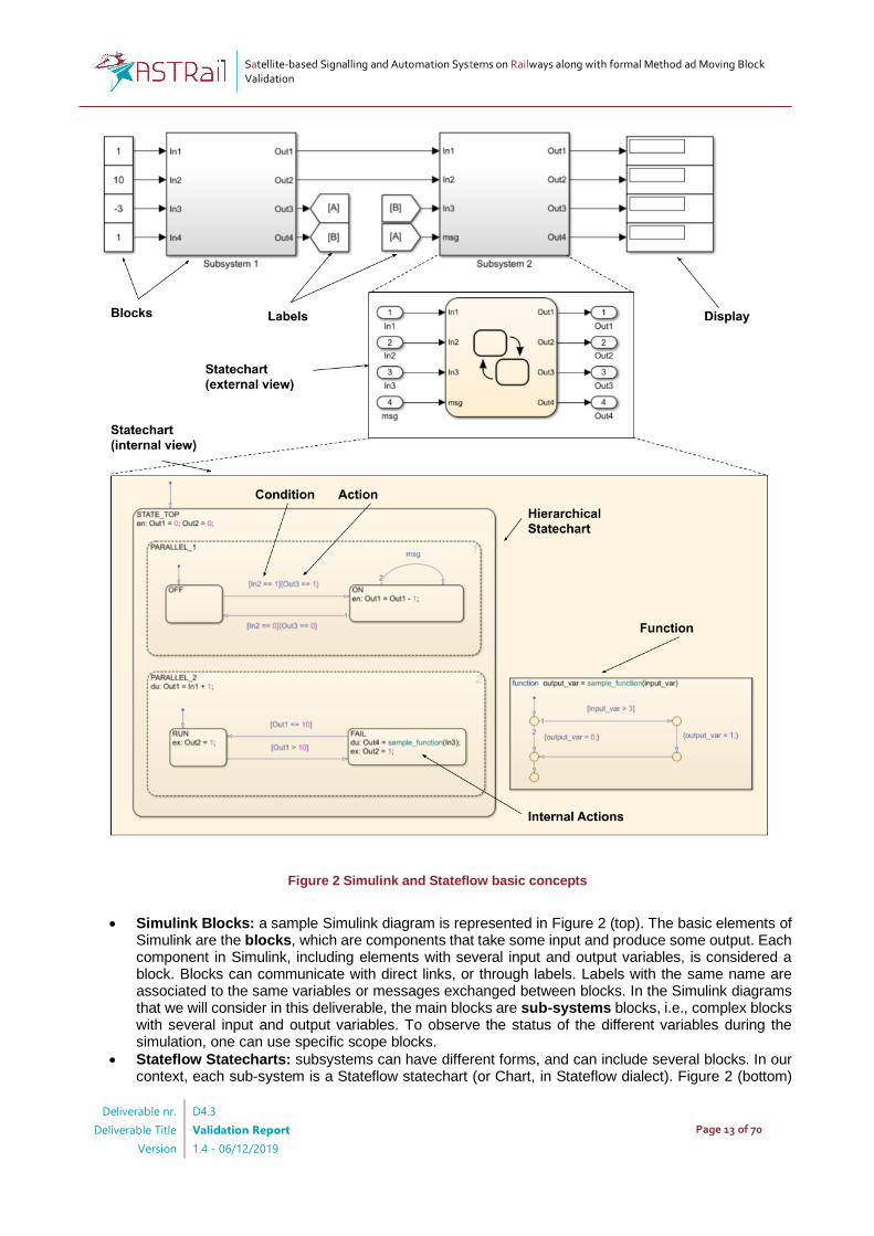
Figure 2 Simulink and Stateflow basic concepts
• Simulink Blocks: a sample Simulink diagram is represented in Figure 2 (top). The basic elements of Simulink are the blocks, which are components that take some input and produce some output. Each component in Simulink, including elements with several input and output variables, is considered a block. Blocks can communicate with direct links, or through labels. Labels with the same name are associated to the same variables or messages exchanged between blocks. In the Simulink diagrams that we will consider in this deliverable, the main blocks are sub-systems blocks, i.e., complex blocks with several input and output variables. To observe the status of the different variables during the simulation, one can use specific scope blocks.
• Stateflow Statecharts: subsystems can have different forms, and can include several blocks. In our context, each sub-system is a Stateflow statechart (or Chart, in Stateflow dialect). Figure 2 (bottom)
Satellite-based Signalling and Automation Systems on Railways along with formal Method ad Moving Block Validation
Deliverable nr.
Deliverable Title
Version
D4.3
Validation Report
1.4 - 06/12/2019
Page 14 of 70
represents a sample statechart. The statechart inherits input and output from the associated sub-system block. Furthermore, it is composed by a set of hierarchical states. The decomposition of states can be parallel (dashed lines, PARALLEL_1 and PARALLEL_2) or mutually exclusive (solid line, for example OFF, ON). Parallel states are actually executed in a sequential order, and the order is visually specified on the chart itself (top-right corner of each parallel state).
• Conditions and Actions: Conditions and actions can be used in the transitions from mutually exclusive states. Conditions are expressed in squared brackets, and actions are expressed in curly brackets. Conditions are normally associated to variables. However, they can also refer to the reception of messages. In this case they do not make use of square brackets.
• Internal Actions: Actions can be defined also within the states. There are three types of actions: entry actions (en), which are executed only once when the system enters the specific state; during actions (du), which are executed at each simulation step; exit action (ex), which are executed when the system exists the state.
• Functions: functions are graphical flowcharts, with conditions and actions analogous to those used for transitions between states. Functions can be called within actions in states, in transitions, and in functions themselves. The main difference between a function and a statechart with mutually exclusive states is that a function is entirely executed within one simulation step, while at each simulation step only one state in a certain hierarchy can be active in a statechart. This is similar to the difference that we have between a C function with nested if-then-else statements, and a C function with a switch case statement. The former is analogous to Stateflow functions. The latter is analogous to Stateflow statecharts with mutually exclusive states.
3.2 Moving Block
3.2.1 Moving Block Overview
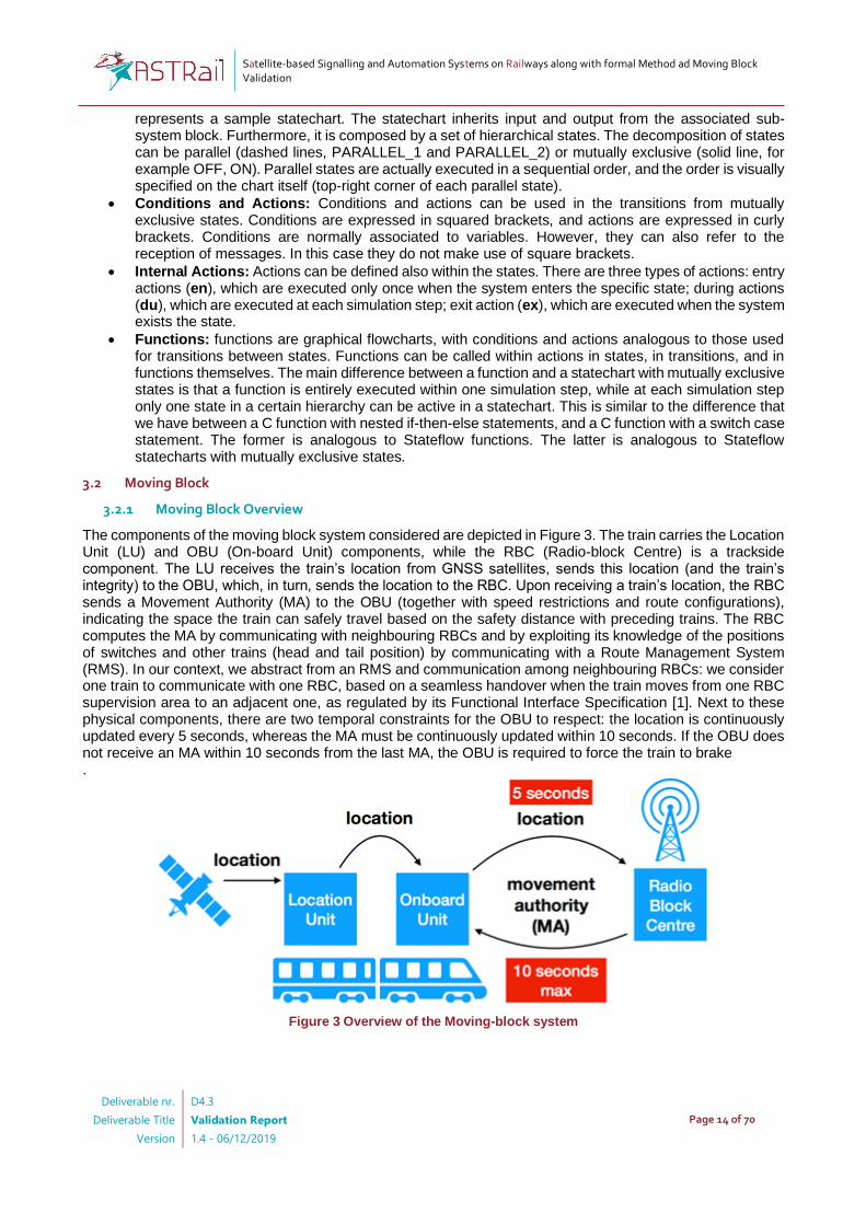
The components of the moving block system considered are depicted in Figure 3. The train carries the Location Unit (LU) and OBU (On-board Unit) components, while the RBC (Radio-block Centre) is a trackside component. The LU receives the train’s location from GNSS satellites, sends this location (and the train’s integrity) to the OBU, which, in turn, sends the location to the RBC. Upon receiving a train’s location, the RBC sends a Movement Authority (MA) to the OBU (together with speed restrictions and route configurations), indicating the space the train can safely travel based on the safety distance with preceding trains. The RBC computes the MA by communicating with neighbouring RBCs and by exploiting its knowledge of the positions of switches and other trains (head and tail position) by communicating with a Route Management System (RMS). In our context, we abstract from an RMS and communication among neighbouring RBCs: we consider one train to communicate with one RBC, based on a seamless handover when the train moves from one RBC supervision area to an adjacent one, as regulated by its Functional Interface Specification [1]. Next to these physical components, there are two temporal constraints for the OBU to respect: the location is continuously updated every 5 seconds, whereas the MA must be continuously updated within 10 seconds. If the OBU does not receive an MA within 10 seconds from the last MA, the OBU is required to force the train to brake .
Figure 3 Overview of the Moving-block system
Satellite-based Signalling and Automation Systems on Railways along with formal Method ad Moving Block Validation
Deliverable nr.
Deliverable Title
Version
D4.3
Validation Report
1.4 - 06/12/2019
Page 15 of 70
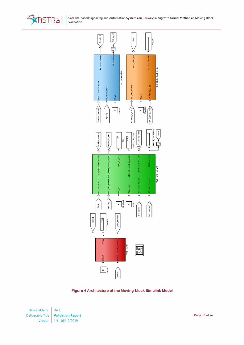
3.2.2 Moving-block Model Architecture
Figure 4 reports the architecture of the model, which includes four main Simulink blocks representing the interacting subsystems, namely OBU, LU, RBC, and Train. Each block communicates with the other blocks by means of input/output messages. For example, the label named location is one of the outputs of the LU, and it is input to the OBU block. This indicates a virtual channel by which a message is exchanged between LU and OBU, including the current train location. Similarly, location_to_RBC is one of the outputs of the OBU block, also serving as input to the RBC block: the OBU location, received from the LU, is passed to the RBC, which, in turn, can compute the MA and send it to the OBU. The OBU is also in charge of activating the brake, and the brake’s status can be visualised in the BRAKE_COMMAND scope element. Similarly, other scope elements are used to visualise a TIMER, indicating the time from the last received MA (2.4 seconds in Figure 4), and SPACE_TO_EOA, which is the space from the current position to the end of the MA (996.4 meters). Following the requirements, failure inputs (OBU_FAIL, RBC_FAIL, and LU_FAIL) are associated to each block to simulate external events that may trigger system failures. In the following sections we describe the behaviour of the different components of the model, namely OBU, LU, RBC and Train.
Satellite-based Signalling and Automation Systems on Railways along with formal Method ad Moving Block Validation
Deliverable nr.
Deliverable Title
Version
D4.3
Validation Report
1.4 - 06/12/2019
Page 16 of 70
Figure 4 Architecture of the Moving-block Simulink Model
Satellite-based Signalling and Automation Systems on Railways along with formal Method ad Moving Block Validation
Deliverable nr.
Deliverable Title
Version
D4.3
Validation Report
1.4 - 06/12/2019
Page 17 of 70
3.2.3 Behaviour of the Moving-block System: OBU Component
Figure 5 reports a high-level view of the behaviour of the OBU component. The model has two main parallel states: MESSAGE_QUEUE_MANAGER and OBU_MAIN. MESSAGE_QUEUE_MANAGER, which appears in all the developed Simulink models, handles the queue of received messages. Specifically, at each clock cycle the queue is emptied, and only the last message received is read and processed. The internal part of the state is not reported in the picture, as this parallel state has solely an ancillary role for the model. OBU_MAIN represents the main behavioural block of the OBU is composed of a statechart of two states, RUN and BRAKE. The system passes from the normal state RUN to the BRAKE state whenever the timer set to receive a movement authority (OBU_out_timer) exceeds 10 seconds, or there is a failure (OBU_fail == 1) or the train is moving and the current space limit is exceeded, i.e., the MA has been violated. The system can return to the RUN state only upon reset (OBU_reset == 1). The RUN state is itself composed of parallel states that handle the different functions of the OBU. Specifically, four states are considered, and described in the following.
• GENERATE_LOCATION_REQUEST (Figure 6). Every 500 milliseconds (see condition after(500, ms)) a location request message is sent to the LU.
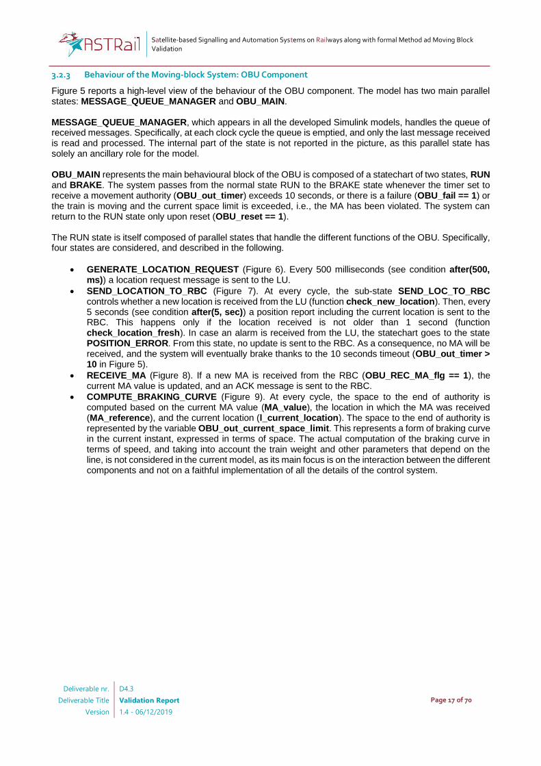
• SEND_LOCATION_TO_RBC (Figure 7). At every cycle, the sub-state SEND_LOC_TO_RBC controls whether a new location is received from the LU (function check_new_location). Then, every 5 seconds (see condition after(5, sec)) a position report including the current location is sent to the RBC. This happens only if the location received is not older than 1 second (function check_location_fresh). In case an alarm is received from the LU, the statechart goes to the state POSITION_ERROR. From this state, no update is sent to the RBC. As a consequence, no MA will be received, and the system will eventually brake thanks to the 10 seconds timeout (OBU_out_timer > 10 in Figure 5).
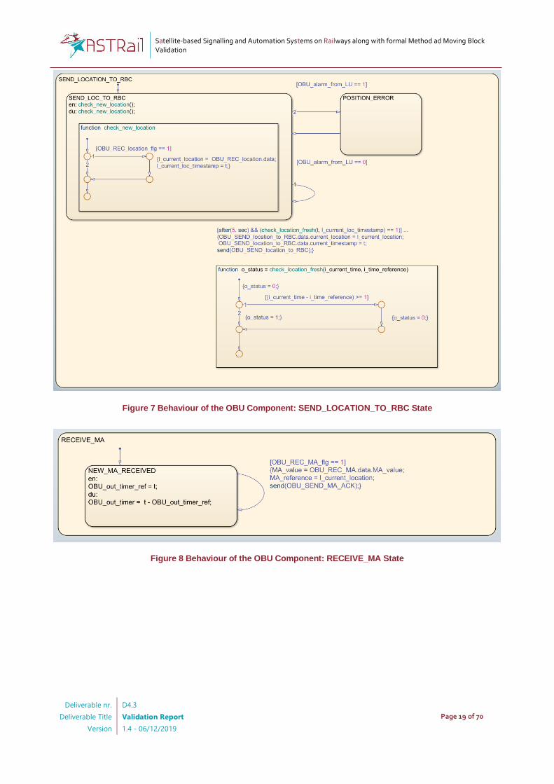
• RECEIVE_MA (Figure 8). If a new MA is received from the RBC (OBU_REC_MA_flg == 1), the current MA value is updated, and an ACK message is sent to the RBC.
• COMPUTE_BRAKING_CURVE (Figure 9). At every cycle, the space to the end of authority is computed based on the current MA value (MA_value), the location in which the MA was received (MA_reference), and the current location (l_current_location). The space to the end of authority is represented by the variable OBU_out_current_space_limit. This represents a form of braking curve in the current instant, expressed in terms of space. The actual computation of the braking curve in terms of speed, and taking into account the train weight and other parameters that depend on the line, is not considered in the current model, as its main focus is on the interaction between the different components and not on a faithful implementation of all the details of the control system.

Satellite-based Signalling and Automation Systems on Railways along with formal Method ad Moving Block Validation
Deliverable nr.
Deliverable Title
Version
D4.3
Validation Report
1.4 - 06/12/2019
Page 18 of 70
Figure 5 Behaviour of the OBU component: High-level view
Figure 6 Behaviour of the OBU Component: GENERATE_LOCATION_REQUEST State
Satellite-based Signalling and Automation Systems on Railways along with formal Method ad Moving Block Validation
Deliverable nr.
Deliverable Title
Version
D4.3
Validation Report
1.4 - 06/12/2019
Page 19 of 70
Figure 7 Behaviour of the OBU Component: SEND_LOCATION_TO_RBC State
Figure 8 Behaviour of the OBU Component: RECEIVE_MA State

Satellite-based Signalling and Automation Systems on Railways along with formal Method ad Moving Block Validation
Deliverable nr.
Deliverable Title
Version
D4.3
Validation Report
1.4 - 06/12/2019
Page 20 of 70
Figure 9 Behaviour of the OBU Component: COMPUTE_BRAKING_CURVE State
3.2.4 Behaviour of the Moving-block System: LU Component
Figure 10 represents the behaviour of the LU component. Besides the support state MESSAGE_QUEUE_MANAGER, which handles the message queue, and was already described in Section 3.2.3, we have a main state called LU_MAIN. This is composed of two sub-states: SEND_LOC and LU_FAIL. The former sends a position report message including the current location of the train, every time a request is received from the OBU (LU_REC_location_reques_flg == 1). Whenever a failure occurs, the LU goes into the LU_FAIL state, and raises an alarm, which is received by the OBU (out_alarm == 1).
Figure 10 Behaviour of the LU Component
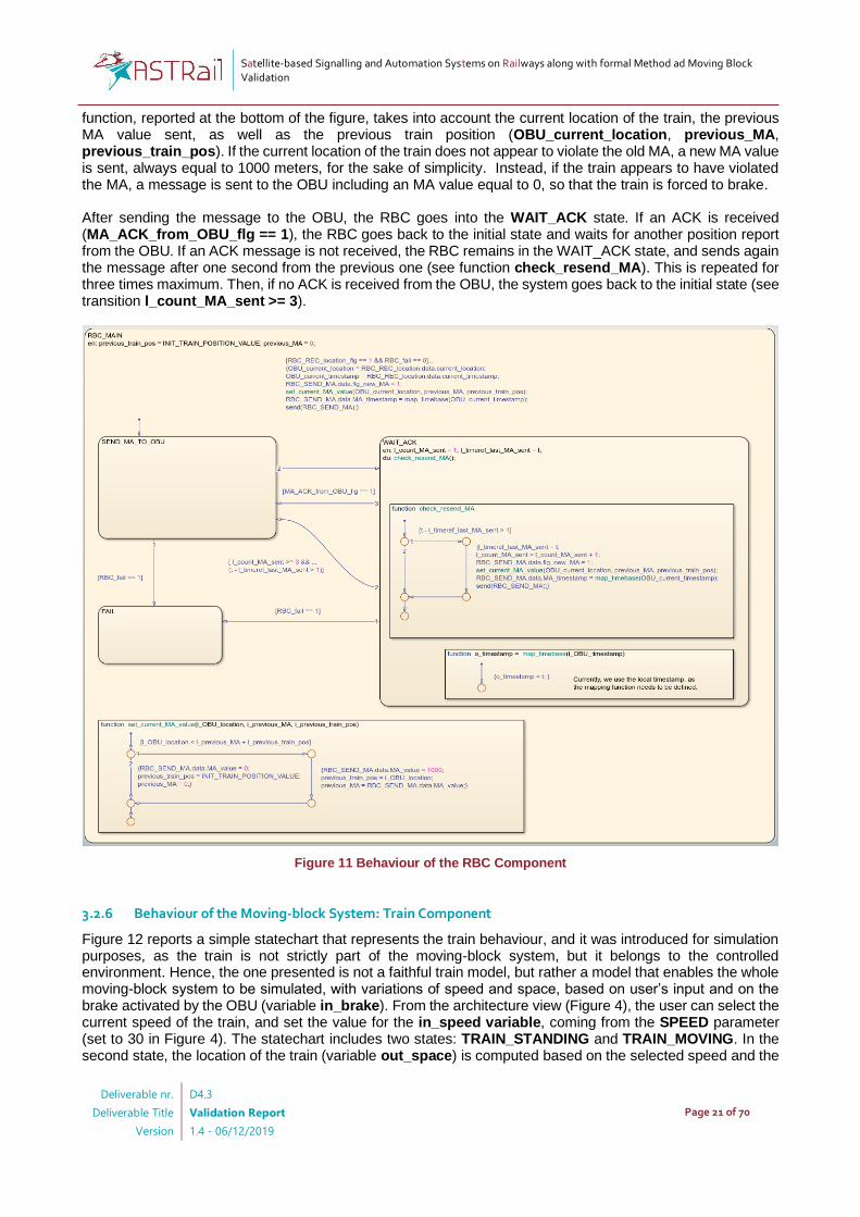
3.2.5 Behaviour of the Moving-block System: RBC Component
Figure 11 represents the main behaviour of the RBC system (here, we do not report the MESSAGE_QUEUE_MANAGER state, for ease of visualisation). The system has three states, namely: SEND_MA_TO_OBU, WAIT_ACK and FAIL. In the state SEND_MA_TO_OBU, whenever a new location is received (RBC_REC_location_flg == 1) and no failure occurred, a message called RBC_SEND_MA to be sent to the OBU is composed. Such message includes the MA value for the OBU, which is computed by means of the set_current_MA_value function. This
Satellite-based Signalling and Automation Systems on Railways along with formal Method ad Moving Block Validation
Deliverable nr.
Deliverable Title
Version
D4.3
Validation Report
1.4 - 06/12/2019
Page 21 of 70
function, reported at the bottom of the figure, takes into account the current location of the train, the previous MA value sent, as well as the previous train position (OBU_current_location, previous_MA, previous_train_pos). If the current location of the train does not appear to violate the old MA, a new MA value is sent, always equal to 1000 meters, for the sake of simplicity. Instead, if the train appears to have violated the MA, a message is sent to the OBU including an MA value equal to 0, so that the train is forced to brake. After sending the message to the OBU, the RBC goes into the WAIT_ACK state. If an ACK is received (MA_ACK_from_OBU_flg == 1), the RBC goes back to the initial state and waits for another position report from the OBU. If an ACK message is not received, the RBC remains in the WAIT_ACK state, and sends again the message after one second from the previous one (see function check_resend_MA). This is repeated for three times maximum. Then, if no ACK is received from the OBU, the system goes back to the initial state (see transition l_count_MA_sent >= 3).
Figure 11 Behaviour of the RBC Component
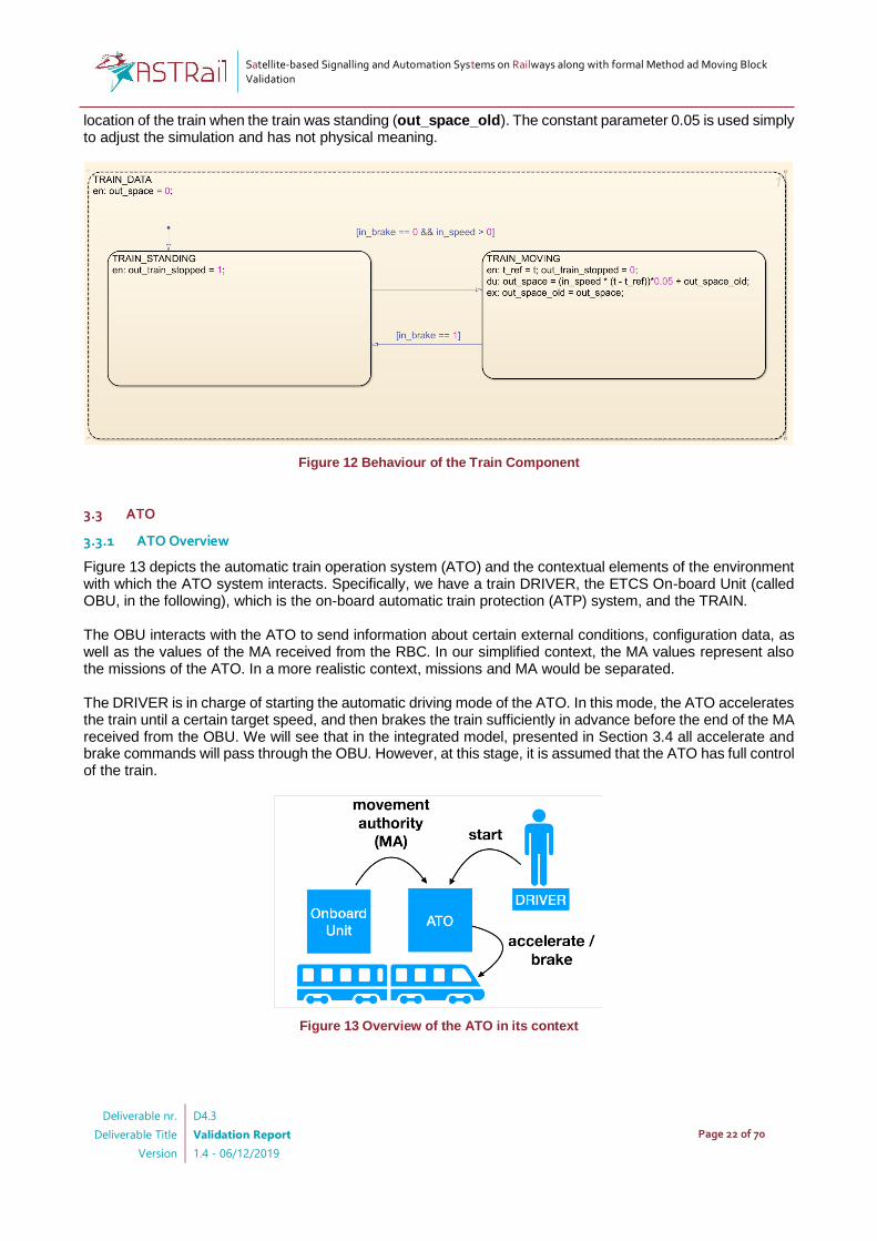
3.2.6 Behaviour of the Moving-block System: Train Component
Figure 12 reports a simple statechart that represents the train behaviour, and it was introduced for simulation purposes, as the train is not strictly part of the moving-block system, but it belongs to the controlled environment. Hence, the one presented is not a faithful train model, but rather a model that enables the whole moving-block system to be simulated, with variations of speed and space, based on user’s input and on the brake activated by the OBU (variable in_brake). From the architecture view (Figure 4), the user can select the current speed of the train, and set the value for the in_speed variable, coming from the SPEED parameter (set to 30 in Figure 4). The statechart includes two states: TRAIN_STANDING and TRAIN_MOVING. In the second state, the location of the train (variable out_space) is computed based on the selected speed and the
Satellite-based Signalling and Automation Systems on Railways along with formal Method ad Moving Block Validation
Deliverable nr.
Deliverable Title
Version
D4.3
Validation Report
1.4 - 06/12/2019
Page 22 of 70
location of the train when the train was standing (out_space_old). The constant parameter 0.05 is used simply to adjust the simulation and has not physical meaning.
Figure 12 Behaviour of the Train Component
3.3 ATO
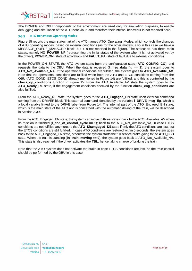
3.3.1 ATO Overview
Figure 13 depicts the automatic train operation system (ATO) and the contextual elements of the environment with which the ATO system interacts. Specifically, we have a train DRIVER, the ETCS On-board Unit (called OBU, in the following), which is the on-board automatic train protection (ATP) system, and the TRAIN. The OBU interacts with the ATO to send information about certain external conditions, configuration data, as well as the values of the MA received from the RBC. In our simplified context, the MA values represent also the missions of the ATO. In a more realistic context, missions and MA would be separated. The DRIVER is in charge of starting the automatic driving mode of the ATO. In this mode, the ATO accelerates the train until a certain target speed, and then brakes the train sufficiently in advance before the end of the MA received from the OBU. We will see that in the integrated model, presented in Section 3.4 all accelerate and brake commands will pass through the OBU. However, at this stage, it is assumed that the ATO has full control of the train.
Figure 13 Overview of the ATO in its context

Satellite-based Signalling and Automation Systems on Railways along with formal Method ad Moving Block Validation
Deliverable nr.
Deliverable Title
Version
D4.3
Validation Report
1.4 - 06/12/2019
Page 23 of 70
3.3.2 ATO Model Architecture
Figure 14 represents a high-level view of the ATO component (light grey block) in its environment. The environment is composed of three components:
• DRIVER (cyan block), which starts the ATO system (label POWER_ON), commands the automatic driving function (label DRIVE), and activates the train brake lever (label TBL). These commands are set by the user, and forwarded to the ATO.
• OBU (Stub) (green block), which is a simplified version of the OBU considered in the moving-block system from Section 3.2, and limited to those functionalities that are relevant for the ATO, namely sending the movement authority (label MA), setting the status of the external conditions that allow the ATO to change its internal states (ATO_COND, ETCS_COND), and sending data configuration messages (DATA) when requested by the ATO at start-up (DATA_REQ).
• TRAIN (red block), which is again a representation of the train dynamics, although slightly more complex with respect to the one used for the moving-block system and presented in Section 3.2.6. Indeed, the block takes as input the acceleration and braking commands coming from the ATO (ACCELERATE, BRAKE, full_service_brake), and changes Speed and Space accordingly. Two parameters (INC_CONST_SPEED, INC_CONST_SPACE) are used as input to enable a realistic simulation.
The ATO component takes input from the different elements of the environment and produces output, mainly towards the TRAIN component. Besides the input to the ATO already mentioned above, the ATO has also two external input variables, which are in_EXT_CONST_START_BRAKE, a parameter to decide when the system shall start braking with respect to the end of the MA (currently arbitrarily set to 0.4), and in_EXT_fault, which simply injects a failure in the ATO system.
Figure 14 Architecture of the ATO Model
In the following section, we describe the internal behaviour of the ATO block, including also some details of the TRAIN block that are relevant to understand the ATO behaviour.
Satellite-based Signalling and Automation Systems on Railways along with formal Method ad Moving Block Validation
Deliverable nr.
Deliverable Title
Version
D4.3
Validation Report
1.4 - 06/12/2019
Page 24 of 70
The DRIVER and OBU components of the environment are used only for simulation purposes, to enable debugging and simulation of the ATO behaviour, and therefore their internal behaviour is not reported here.
3.3.3 ATO Behaviour: Operating Modes
Figure 15 reports the main statechart of the ATO named ATO_Operating_Modes, which controls the changes of ATO operating modes, based on external conditions (as for the other models, also in this case we have a MESSAGE_QUEUE_MANAGER block, but it is not reported in the figure). The statechart has three main states, namely NO_POWER_NP (representing the initial status of the system when it is not activated yet by the driver), POWER_ON (state of activation) and FAULT_FA (state of fault due to external conditions). In the POWER_ON_STATE, the ATO system starts from the configuration state (ATO_CONFIG_CO), and requests the data to the OBU. When the data is received (l_msg_data_flg == 1), the system goes to ATO_Not_Available_NA. If the operational conditions are fulfilled, the system goes to ATO_Available_AV. Note that the operational conditions are fulfilled when both the ATO and ETCS conditions coming from the OBU (ATO_COND, ETCS_COND already mentioned in Figure 14) are fulfilled, and this is controlled by the check_op_conditions function in Figure 15. From the ATO_Available_AV state the system goes to the ATO_Ready_RE state, if the engagement conditions checked by the function check_eng_conditions are also fulfilled. From the ATO_Ready_RE state, the system goes to the ATO_Engaged_EN state upon external command coming from the DRIVER block. This external command identified by the variable l_DRIVE_msg_flg, which is a local variable linked to the DRIVE label from Figure 14. The internal part of the ATO_Engaged_EN state, which is the main state of the ATO and is concerned with the automatic driving of the train, will be described in Section 3.3.4. From the ATO_Engaged_EN state, the system can move to three states: back to the ATO_Available_AV when its mission is finished (l_end_of_control_cycle == 1); back to the ATO_Not_Available_NA, in case ETCS conditions are not fulfilled anymore; to the ATO_Disengaged_DE state if only the ATO conditions are lost, but the ETCS conditions are still fulfilled. In case ATO conditions are restored within 5 seconds, the system goes back to the ATO_Engaged_EN state, otherwise the system starts the full service brake going to the ATO_FSB state. When the train is standing (in_train_moving == 0), the system goes back to ATO_Not_Available_NA. This state is also reached if the driver activates the TBL, hence taking charge of braking the train. Note that the ATO system does not activate the brake in case ETCS conditions are lost, as the train control should be performed by the OBU in this case.

Satellite-based Signalling and Automation Systems on Railways along with formal Method ad Moving Block Validation
Deliverable nr.
Deliverable Title
Version
D4.3
Validation Report
1.4 - 06/12/2019
Page 25 of 70
Figure 15 Statechart representing the Operating Modes of the ATO
Satellite-based Signalling and Automation Systems on Railways along with formal Method ad Moving Block Validation
Deliverable nr.
Deliverable Title
Version
D4.3
Validation Report
1.4 - 06/12/2019
Page 26 of 70
3.3.4 ATO Behaviour: Speed Control and Train
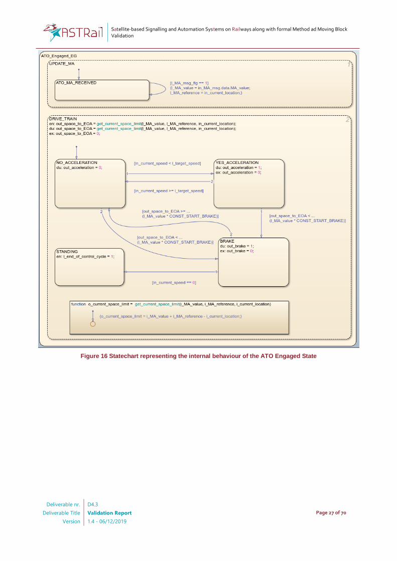
In this section we describe how the ATO system controls the train speed, based on the MA messages received from the OBU. Figure 16 reports the internal behaviour of the engaged state of the ATO, called ATO_Engaged_EN. Instead, Figure 17 reports the simple model of the train, which is controlled by the ATO. The statechart ATO_Engaged_EN has two main states, UPDATE_MA and DRIVE_TRAIN. The former takes care of unpacking new MA messages coming from the OBU. The latter is in charge of commanding acceleration (variable out_acceleration) and brake (out_brake) based on the space to the end of the MA (out_space_to_EOA) which is continuously computed by the function get_current_space_limit, analogous to the one already described in Section 3.2.3, and included in the OBU of the moving-block system. The DRIVE_TRAIN statechart has four exclusive states: NO_ACCELERATION, in which the train does not accelerate; YES_ACCELERATION, which is active until the target speed is reached; BRAKE, which is activated if the space to the end of the MA is lower than a certain rate set by the input parameter CONST_START_BRAKE; STANDING, which is the final state, reached when the mission is finished, the train is standing, and no new MA is received. The states in the ATO_Engaged_EN statechart have some corresponding states in the statechart that represents the train behaviour in Figure 17. This statechart includes the states TRAIN_STOPPED, TRAIN_MOVING, TRAIN_CONSTANT_SPEED and TRAIN_BRAKING, which have an intuitive role. As the model of the train is a simplified version of the actual dynamic of a train, the space and the speed are increased constantly according to the input parameters INC_CONST_SPEED and INC_COST_SPACE whenever the train is moving. When simulating the model, these parameters shall be adjusted to enable a realistic simulation: they are currently set to 0.001 and 0.0001, but different values maybe set if the simulation is too slow or too fast (this depends on several factors, including the characteristics of the PC used to run the simulation).
Satellite-based Signalling and Automation Systems on Railways along with formal Method ad Moving Block Validation
Deliverable nr.
Deliverable Title
Version
D4.3
Validation Report
1.4 - 06/12/2019
Page 27 of 70
Figure 16 Statechart representing the internal behaviour of the ATO Engaged State

Satellite-based Signalling and Automation Systems on Railways along with formal Method ad Moving Block Validation
Deliverable nr.
Deliverable Title
Version
D4.3
Validation Report
1.4 - 06/12/2019
Page 28 of 70
Figure 17 Statechart representing the Train model for the ATO

Satellite-based Signalling and Automation Systems on Railways along with formal Method ad Moving Block Validation
Deliverable nr.
Deliverable Title
Version
D4.3
Validation Report
1.4 - 06/12/2019
Page 29 of 70
Figure 18 Multiple MA received and corresponding speed and space
To understand the interaction between the different components that appear in Figure 14, and especially the ATO, the OBU (Stub) and the TRAIN, it is useful to look at the scenario reported in Figure 18. The figure shows the space crossed by the train, its speed, and the variations of the variable out_space_to_EOA indicating the space remaining to the end of the MA. In the scenario, four MA messages are received, with a constant value of 1000 meters. At each iteration, the train accelerates until the speed of 80 Km/h is reached, keeps its speed constant and then starts braking when approaching the end of the MA. If a new MA is received, the train starts accelerating again.
Satellite-based Signalling and Automation Systems on Railways along with formal Method ad Moving Block Validation
Deliverable nr.
Deliverable Title
Version
D4.3
Validation Report
1.4 - 06/12/2019
Page 30 of 70
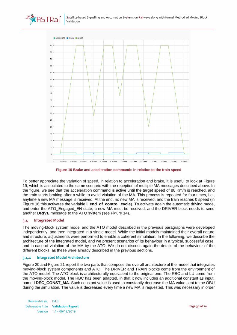
Figure 19 Brake and acceleration commands in relation to the train speed
To better appreciate the variation of speed, in relation to acceleration and brake, it is useful to look at Figure 19, which is associated to the same scenario with the reception of multiple MA messages described above. In the figure, we see that the acceleration command is active until the target speed of 80 Km/h is reached, and the train starts braking after a while to avoid violation of the MA. This process is repeated for four times, i.e., anytime a new MA message is received. At the end, no new MA is received, and the train reaches 0 speed (in Figure 16 this activates the variable l_end_of_control_cycle). To activate again the automatic driving mode, and enter the ATO_Engaged_EN state, a new MA must be received, and the DRIVER block needs to send another DRIVE message to the ATO system (see Figure 14).
3.4 Integrated Model
The moving-block system model and the ATO model described in the previous paragraphs were developed independently, and then integrated in a single model. While the initial models maintained their overall nature and structure, adjustments were performed to enable a coherent simulation. In the following, we describe the architecture of the integrated model, and we present scenarios of its behaviour in a typical, successful case, and in case of violation of the MA by the ATO. We do not discuss again the details of the behaviour of the different blocks, as these were already described in the previous sections.
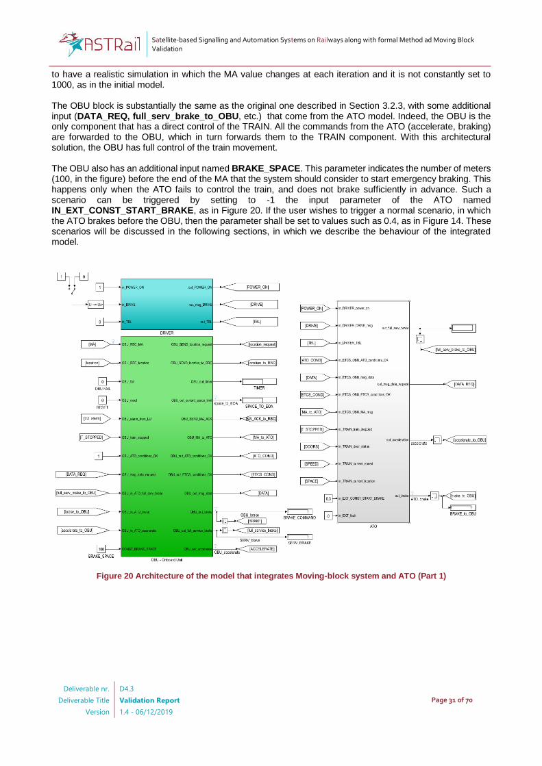
3.4.1 Integrated Model Architecture
Figure 20 and Figure 21 report the two parts that compose the overall architecture of the model that integrates moving-block system components and ATO. The DRIVER and TRAIN blocks come from the environment of the ATO model. The ATO block is architecturally equivalent to the original one. The RBC and LU come from the moving-block model. The RBC has been adapted, in that it now includes an additional constant as input, named DEC_CONST_MA. Such constant value is used to constantly decrease the MA value sent to the OBU during the simulation. The value is decreased every time a new MA is requested. This was necessary in order
Satellite-based Signalling and Automation Systems on Railways along with formal Method ad Moving Block Validation
Deliverable nr.
Deliverable Title
Version
D4.3
Validation Report
1.4 - 06/12/2019
Page 31 of 70
to have a realistic simulation in which the MA value changes at each iteration and it is not constantly set to 1000, as in the initial model. The OBU block is substantially the same as the original one described in Section 3.2.3, with some additional input (DATA_REQ, full_serv_brake_to_OBU, etc.) that come from the ATO model. Indeed, the OBU is the only component that has a direct control of the TRAIN. All the commands from the ATO (accelerate, braking) are forwarded to the OBU, which in turn forwards them to the TRAIN component. With this architectural solution, the OBU has full control of the train movement. The OBU also has an additional input named BRAKE_SPACE. This parameter indicates the number of meters (100, in the figure) before the end of the MA that the system should consider to start emergency braking. This happens only when the ATO fails to control the train, and does not brake sufficiently in advance. Such a scenario can be triggered by setting to -1 the input parameter of the ATO named IN_EXT_CONST_START_BRAKE, as in Figure 20. If the user wishes to trigger a normal scenario, in which the ATO brakes before the OBU, then the parameter shall be set to values such as 0.4, as in Figure 14. These scenarios will be discussed in the following sections, in which we describe the behaviour of the integrated model.
Figure 20 Architecture of the model that integrates Moving-block system and ATO (Part 1)

Satellite-based Signalling and Automation Systems on Railways along with formal Method ad Moving Block Validation
Deliverable nr.
Deliverable Title
Version
D4.3
Validation Report
1.4 - 06/12/2019
Page 32 of 70
Figure 21 Architecture of the model that integrates Moving-block system and ATO (Part 2)
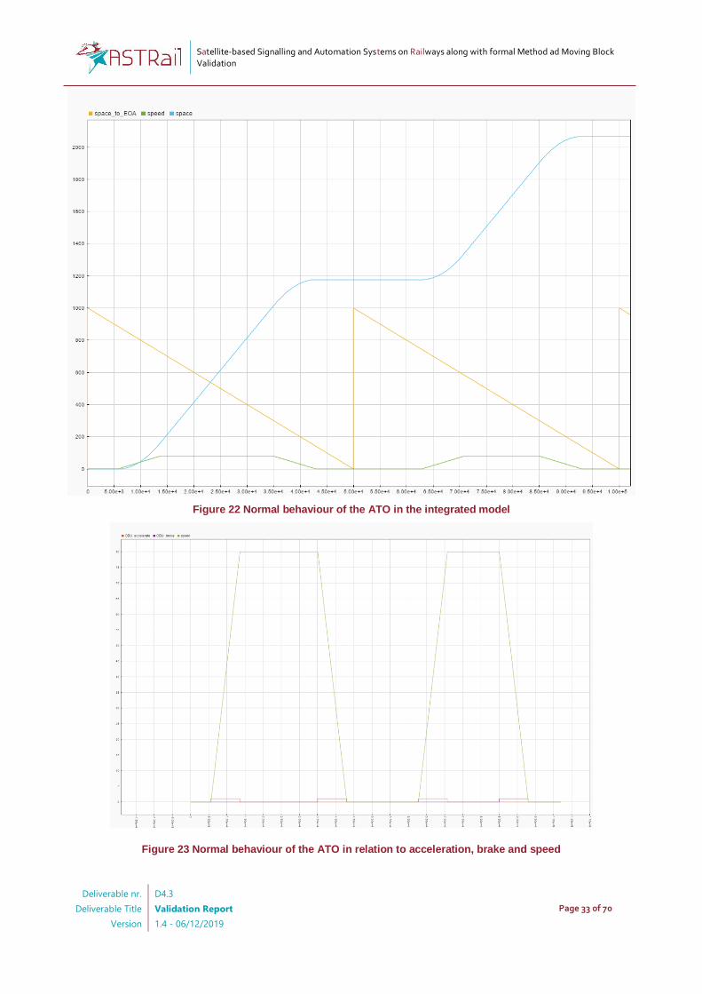
3.4.2 Integrated Model Behaviour
Figure 22 and Figure 23 represent the main variables of the considered integrated model, in a normal scenario. In the scenario, the ATO drives the train based on the MA produced by the RBC and forwarded by the OBU, and the OBU does not activate the emergency braking. Specifically, Figure 22 shows the value of the signal space_to_EOA as computed by the OBU, which varies in relation to the train movement and to the new MA value received from the RBC, which decreases constantly each time the OBU sends a position report. The ATO accelerates until a maximum speed value, and some space before the end of the movement authority, it starts braking. Then, when a new MA is received, the system starts moving again, after the DRIVER has allowed that, by triggering the signal in_DRIVE in Figure 20. Figure 23 focuses on the speed, accelerate and brake variables for the same scenario. Figure 24 shows the behaviour of the system in case the ATO does not stop the train as expected, and the OBU is forced to brake. The MA values included in the messages from the RBC (pink lines) decrease until the OBU starts braking, so that the train is stopped before the end of the MA.
Satellite-based Signalling and Automation Systems on Railways along with formal Method ad Moving Block Validation
Deliverable nr.
Deliverable Title
Version
D4.3
Validation Report
1.4 - 06/12/2019
Page 33 of 70
Figure 22 Normal behaviour of the ATO in the integrated model
Figure 23 Normal behaviour of the ATO in relation to acceleration, brake and speed

Satellite-based Signalling and Automation Systems on Railways along with formal Method ad Moving Block Validation
Deliverable nr.
Deliverable Title
Version
D4.3
Validation Report
1.4 - 06/12/2019
Page 34 of 70
Figure 24 Case of MA violation by the ATO
3.5 Requirements Elicitation and Simulation with Simulink: Observations
This section is dedicated to discuss the observations through the usage of Simulink-Stateflow for early requirements elicitation and simulation in the context of ASTRail.
• Immediate visual feedback on system behaviour: when modelling through Simulink-Stateflow, the user can simulate the requirements, and have an immediate feedback of the system behaviour. This is not possible with a static diagram. Such feedback allows the user to increase their confidence on the correctness of the requirements, but also to identify incomplete requirements. A typical case of incomplete requirements occurs when one observes the simulation flipping between neighbouring states: this may occur because the conditions to remain in a certain state are not well defined. In other cases this may occur because there are variations of the input variables that are too frequent, leading to frequent switches between states. A case of incomplete, or too generic, requirements emerge when there is a the need to take some practical decision when modelling the system. Sometimes, the decisions were not necessarily guided by the requirements, which tend to abstract away from concrete behaviours. By asking the domain expert for clarifications, it was possible to further refine the requirements.
• Ease of interpretation for domain experts: in our context, the models were developed by formal methods experts, and were agreed by the domain expert. After an explanation of the principles of the Simulink-Stateflow language, and using the images of the developed Simulink-Stateflow diagrams as references, the domain expert was able to pinpoint undesired behaviour and defects in the model. At the same time, the domain expert could more easily visualise problems with the requirements that were used as a source to define the model, and take corrective actions.
• Simulation time depends on multiple factors: the model and its parameters have been set to execute a simulation in a reasonable amount of time, and observe the train movement, acceleration and speed with some degree of realism. The goal was to have a feeling of the overall behaviour, and not to find
Satellite-based Signalling and Automation Systems on Railways along with formal Method ad Moving Block Validation
Deliverable nr.
Deliverable Title
Version
D4.3
Validation Report
1.4 - 06/12/2019
Page 35 of 70
the correct values of each parameter. However, the simulation time may have very relevant variations, also using the same parameters’ values. These time variations are related to the processing time of the simulation, and may depend on several factors, including the size of the simulated model, and the technical capabilities of the PC. The reader will notice that in Figure 14 the parameters for the train INC_CONST_SPEED and INC_CONST_SPACE, which are used to increase speed and space of the train, are set to 0.001 and 0.0001, respectively. In Figure 21, where the integrated model is presented, these parameters are set to 0.1 and 0.01. This increase in the parameter was driven by the fact that, since the model was larger, the previous parameters would be too low to have a realistic change of the values of space and speed. Overall, when using Simulink-Stateflow for the purpose of a realistic, early simulation, these aspects need to be taken into account.
• Nondeterminism not supported: the Stateflow language does not support nondeterministic choices. This implies that the user has to define all the input and associated output, without leaving space for nondeterministic behaviour. On the one hand, this leads to a more faithful representation of the actual code that will run on the real system, which will be deterministic. On the other hand, this leaves less space to abstract away from deterministic behaviours that are not decided during the early stages of development, therefore leading to a more complex, but also more restricted model.
• Not a faithful model of reality: while the user is constrained to take some choices to let the simulation run, some of the choices taken are unavoidably a simplification of reality. For example, in Figure 11, the RBC always sends a MA with a value of 1000 meters. Although this allows the user to have an acceptable simulation as shown in Figure 18, this is not what would happen in reality, as the value of the MA may depend from the train position in relation to other trains. When integrating the moving-block system with the ATO, another problem emerged: the MA value should be reduced in a progressive manner, in order to have the ATO brake the train (we recall that the ATO mission is equivalent to the MA in this model). To address this issue and have the simulation run presented in Figure 22, the RBC needed to be modified so that it would decrease the MA value each time an MA was sent. This is of course a simplification of reality, oriented to enable a coherent collective behaviour of the different components. This is acceptable at this stage of development, as our goal is to assess the logic of interaction. However, when more detailed models are defined, these issues need to be considered, and realistic choices need to be taken.

Satellite-based Signalling and Automation Systems on Railways along with formal Method ad Moving Block Validation
Deliverable nr.
Deliverable Title
Version
D4.3
Validation Report
1.4 - 06/12/2019
Page 36 of 70
4 Qualitative verification
In this section we provide a description of the qualitative/functional formal specification and verification process followed, based on the process described in Sect. 2.2.2. As said in Section 2, the initial step of the validation process has been the refinement of the initial moving block model, its extension with ATO modelling, and the animation of the composition with the Simulink-Stateflow tool. The result of this step is a stable set of natural language as reported in Annex A – System Requirements. At this point, our interest is to define a formal model, consistent with respect to established requirements, upon which to verify the functional (behavioural) requirements of the system. Our choice is to pass from the initial requirements and initial Simulink model towards a preliminary behavioural semi-formal description of the system based on UML statecharts. Before tackling the issue of translating the design of the source specification language of a formal-verification tool, that could in principle be any of tools available at the state of art (e.g. CADP, ProB, SPIN), it is important to have a system design that is as clear as possible. The Simulink model might play with some success this role, but it has three main drawbacks: the first one is that it relies on a proprietary notation which only the commercial tool is able to animate (and partly verify), the second one are the strong assumptions made in the composition of concurrent, but independent, subsystems (which are sequentially ordered and executed synchronously one step at a time), and the third one is that the Simulink model is inherently deterministic therefore specific choices need to be taken, possibly leading to over specification, to support the system simulation. Our choice of using standard UML has been impacted by the fact that this notation has a public specification (OMG UML2.5 Specification)1, a rather clearly defined semantics when certain problematic aspects are not used, and the support of a rich set of design, transformation, animation and verification tools some of which are commercial only (e.g. IBM Rational Software Architect2, MagicDraw3, PTC Integrity Modeller4, Enterprise Architect5), while others free and open source (e.g. . OpenMBEE6), UML Designer7, UMC8, Papyrus UML9). Clearly also the standard UML choice is not immune from drawbacks, both in terms of tool support and specification language aspects, with which we will have to deal. In Section 4.1 we will show our reference UML description of the system, while in Section 4.2 we will describe the followed approach for translation the UML description into a real formal model based on the Event B notation and in Section 4.3 the present to verification process conducted with the tool ProB while in Section 4.4 we will present some conclusions and observations.
4.1 The UML system description
In this section, after a brief summary of the graphical elements used in the diagrams (subsection 4.1.1), we will hint the main characteristics of our UML modelling of the Moving Block system and the ATO system (subsection 4.1.2), before presenting the detailed UML models of the OBU (subsection 4.1.3), RBC (subsection 4.1.4), and ATO (subsection 4.1.5) system components.
4.1.1 Briefs on the used UML statecharts notation
In the following sections we will present a graphical representation of the OBU, RBC, ATO components of the system. Those graphical representations will make essentially use of the following symbols:
denoting the initial state of a composite sequential state.
1 https://www.omg.org/spec/UML/2.5.1/PDF 2 https://www.ibm.com/developerworks/downloads/r/architect/index.html 3 https://www.nomagic.com/products/magicdraw 4 www.ptc.com 5 https://sparxsystems.com/products/ea 6 http://www.openmbee.org 7 http://www.umldesigner.org/ 8 https://fmt.isti.cnr.it/umc 9 https://www.eclipse.org/papyrus/

Satellite-based Signalling and Automation Systems on Railways along with formal Method ad Moving Block Validation
Deliverable nr.
Deliverable Title
Version
D4.3
Validation Report
1.4 - 06/12/2019
Page 37 of 70
denoting the exit point from a composite state (or submachine)
denoting a simple state of the model
denoting a composite state of the system separately expanded (i.e. a submachine).
denoting the information associated to a transition between states, where in particular: - The red identifier represents a unique label associated to the edge (used for the ProB translations) - The trigger part (on the left side of "/") denotes the event triggering the transition (highlighted in italic) and possible a guard condition. In particular: The trigger "tick" denotes a clock event signalling the passing of 500 ms. The trigger "istep" denotes the execution of an internal step, not trigger by any external event. - Transitions without trigger (with trigger represented by "-") denote "UML completion transitions" and, as required by the UML semantics, have a higher priority w.r.t all other triggered transitions. - The actions part (on the right side of "/") denotes the sequence of actions performed when the transition is fired. - The action of sending a signal to another active component is highlighted using a bold case. - The GREEN IDENTIFIERS are used to denote the abstract events corresponding to the triggering of the transition (useful for mapping the properties to be verified to the actual system evolutions). Notice that the red and green parts of this information are not part of the UML specification and have just an informative role (with no semantic effects). For example the diagram fragment illustrated in Figure 25 A statechart diagram fragment describes that when the state checkMSG is active, when the signal istep can be dispatched from the event pool, and when the
guard LastMA != null is true, then the signal istep can be removed from the pool and the object can
move into the update_BC state, after sending to the RBC object the msgACK signal. That system evolution,
to which has been given the name o12_new_MA corresponds the to tree abstract events (maybe mentioned
in the requirements) i.e. the fact of having received a new MA (NEW_MA),the fact of having sent the
corresponding ACK (SEND_ACK), and the sending of the MA data to the ATO (NOTIFY_MA).
Figure 25 A statechart diagram fragment
We refer to the OMG UML2.5 Specification - Section 14 State Machines - for a more detailed and complete description of the semantics of UML statecharts and of the statecharts graphical notation.
4.1.2 Some differences w.r.t Simulink/Stateflow modelling
The semi-formal specification language used for this step, and the necessary choices to be performed in the modelling, inevitably introduce a specific language/tool flavour to the result. This is the reason for which the formal model resulting from this step is somewhat different from the Simulink model already developed during the requirements elicitation phase. Some examples between the two semi-formal methodologies of system design are the following:
Satellite-based Signalling and Automation Systems on Railways along with formal Method ad Moving Block Validation
Deliverable nr.
Deliverable Title
Version
D4.3
Validation Report
1.4 - 06/12/2019
Page 38 of 70
- The Simulink model relies on internal timers to represent time-related aspects of the model, while our UML models relies on explicit "tick" signals arriving from the environment as a way to represent the same aspects.
- In a Stateflow chart the transitions exiting from a state are numbered and their number represents the order in which they should evaluated for execution, while in UML there is no such numbering and any priority among the exiting transitions should be explicitly modelled by the conditions appearing in the transition guards.
- In Stateflow a transition which has source in a composite state has a higher priority than any transition nested inside the composite state itself, while in UML the converse applies.
- When a Stateflow model includes different statecharts representing concurrent entities, the possible evolutions of the system are obtained by letting each component to advance one step, in a statically fixed order. The UML definition does not actually specify the behaviour of a system composed by several independent state machines. Only in the case of concurrent regions of the same parallel state the UML definition specifies that all the fireable parallel transitions should be fired in the same run-to-completion step in an unspecified order. In our UML model of the system we suppose that the state machines corresponding to the various system components (OBU, RBC, ATO) can evolve independently and asynchronously, being coordinated only through their exchanges of messages, or explicit - time modelling - "tick" signals. We moreover suppose that the event pools associated to each object are plain FIFO queues.
4.1.3 Introduction to the Moving Block and ATO UML modelling
The three main components of our system are the OBU, the RBC, and the ATO. In our case, we abstract from a separate modelling of the LU as an independent entity, and we consider it just an internal sub-activity of the OBU. When not necessary for the verification of the system requirements, the interactions of our main components with other external components of the system are abstracted without explicitly modelling the details of them. For example, when the OBU commands an emergency braking because of an ATP violation, we model this fact as an occurring abstract event ATP_BRAKE (the abstract events occurring as logical effect of a transition are highlighted in green) without actually modelling the sending of signal from the OBU the train component. Following the same abstraction principle, we do not model the precise data and messages being exchanged between OBU and the RBC (or OBU and ATO), like the actual train position data or the actual structure of the movement authority data. From our abstract point of view, it is sufficient to know that a new movement authority has been sent by the RBC and received by the OBU, or that a new Position Report has been sent by the OBU and received by the RBC. In the design of ATO we abstract from the actual values of the current movement authority, the current train position and speed, and therefore from the actual acceleration deceleration commands used to drive the train according to some driving strategy when in the Engaged or Disengaged states. Our model also does not take into consideration all the driving aspects related to the interactions with the Trackside component related, e.g. to the details of the possible train mission data. Finally, we model the OBU and RBC as concurrent, independent periodic activities that are activated with a period of 500 ms, and 500 ms is also the atomic step at which the ATO can perform a state transition. This means, for example, that the ATO receives any relevant data from the OBU no more than once between from one step and the next. No assumptions are made on the possible way in which the OBU, RBC, ATO cycles may overlap, i.e. any interleaving of their internal activities is possible. Since we are using for the modelling only Standard UML notations (i.e. not using any specific UML-RT or SysML profiles) we abstract from a real-time modelling of time and we relate all the temporal system properties the equivalent number of the component cycles. For example, since the OBU cycle is of 500 ms, the requirement of not sending a new Position Report before 5 seconds from the last one is translated into the not sending of a new Position Report before 10 OBU cycle have been completed. Similarly, the requirement of stopping the train if no MA is received within 7 seconds is transformed into the modelling of the train stopping if no MA is received before 14 OBU cycles have been completed.
4.1.4 OBU
Figure 26 shows the high-level structure of the UML OBU state machine.

Satellite-based Signalling and Automation Systems on Railways along with formal Method ad Moving Block Validation
Deliverable nr.
Deliverable Title
Version
D4.3
Validation Report
1.4 - 06/12/2019
Page 39 of 70
The OBU behaviour is that of a cycle that is triggered by a tick signal that arrives every 500 ms. At each cycle, three main sub activities are performed in sequence: 1) the computation of the current train position 2) the (possible) sending of the position of RBC, and 3) the handling of (possibly arrived) messages and update of the Braking Curve (with possible brake
activation in case of ATP violation or MA timeout). If the cycle last more than 500ms a fatal error occurs and the train stops.
Figure 26 OBU State Machine
The computation of a new train position starts with a Request being sent to the Location Unit (LU). The Location Unit replies either with a new position (notified to ATO), or with the notification of the failure to compute the current position. Figure 27 show the expansion of the Compute_Position stub present in Figure 26. The sending of istep signal to the object itself (the OBU) is a necessary trick to avoid the use of transition without trigger (i.e. completion transitions) inside the Send_PR submachine (see Figure 28).
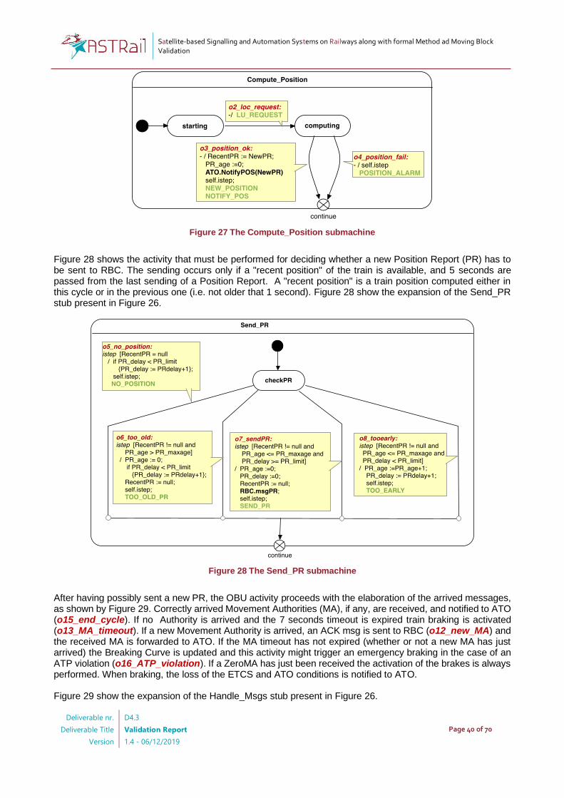
Satellite-based Signalling and Automation Systems on Railways along with formal Method ad Moving Block Validation
Deliverable nr.
Deliverable Title
Version
D4.3
Validation Report
1.4 - 06/12/2019
Page 40 of 70
Figure 27 The Compute_Position submachine
Figure 28 shows the activity that must be performed for deciding whether a new Position Report (PR) has to be sent to RBC. The sending occurs only if a "recent position" of the train is available, and 5 seconds are passed from the last sending of a Position Report. A "recent position" is a train position computed either in this cycle or in the previous one (i.e. not older that 1 second). Figure 28 show the expansion of the Send_PR stub present in Figure 26.
Figure 28 The Send_PR submachine
After having possibly sent a new PR, the OBU activity proceeds with the elaboration of the arrived messages, as shown by Figure 29. Correctly arrived Movement Authorities (MA), if any, are received, and notified to ATO (o15_end_cycle). If no Authority is arrived and the 7 seconds timeout is expired train braking is activated (o13_MA_timeout). If a new Movement Authority is arrived, an ACK msg is sent to RBC (o12_new_MA) and the received MA is forwarded to ATO. If the MA timeout has not expired (whether or not a new MA has just arrived) the Breaking Curve is updated and this activity might trigger an emergency braking in the case of an ATP violation (o16_ATP_violation). If a ZeroMA has just been received the activation of the brakes is always performed. When braking, the loss of the ETCS and ATO conditions is notified to ATO. Figure 29 show the expansion of the Handle_Msgs stub present in Figure 26.
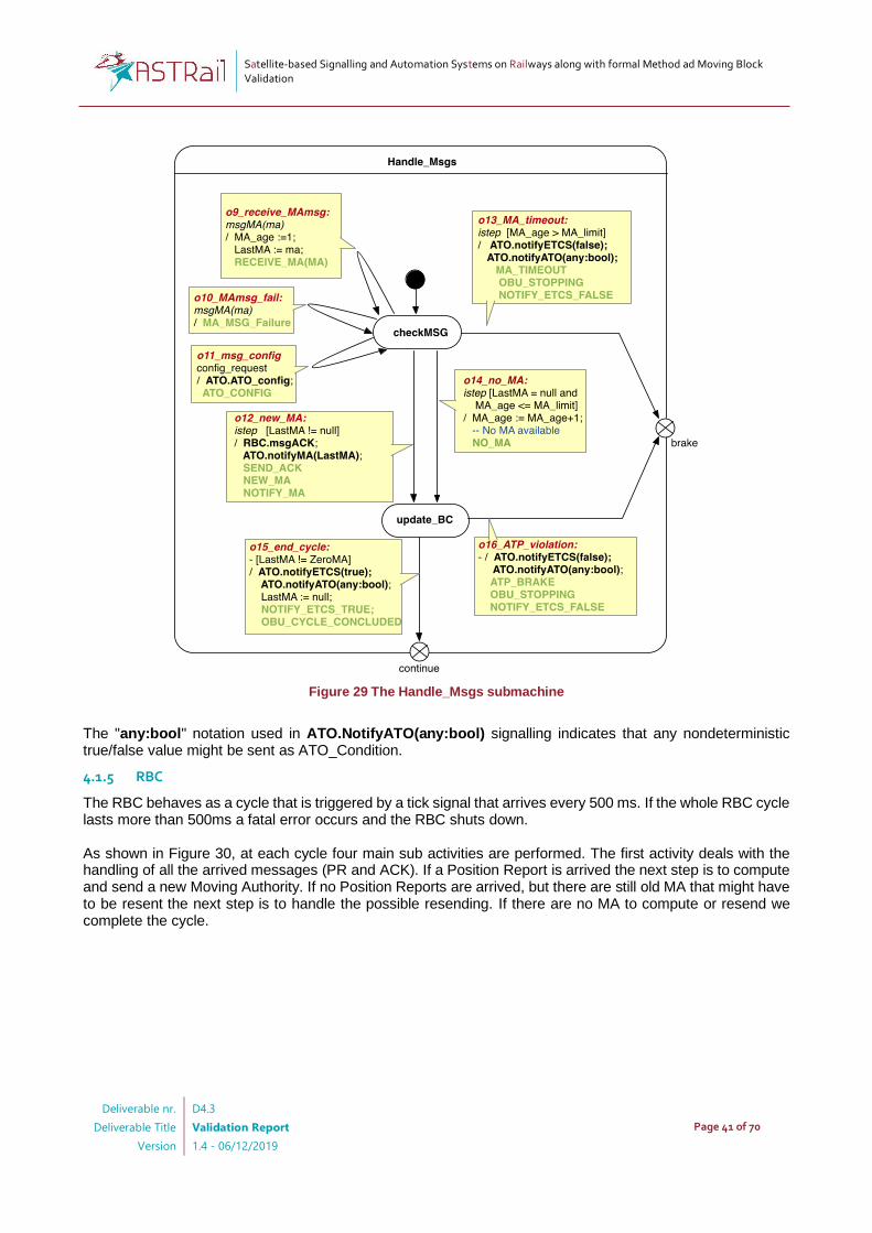
Satellite-based Signalling and Automation Systems on Railways along with formal Method ad Moving Block Validation
Deliverable nr.
Deliverable Title
Version
D4.3
Validation Report
1.4 - 06/12/2019
Page 41 of 70
Figure 29 The Handle_Msgs submachine
The "any:bool" notation used in ATO.NotifyATO(any:bool) signalling indicates that any nondeterministic true/false value might be sent as ATO_Condition.
4.1.5 RBC
The RBC behaves as a cycle that is triggered by a tick signal that arrives every 500 ms. If the whole RBC cycle lasts more than 500ms a fatal error occurs and the RBC shuts down. As shown in Figure 30, at each cycle four main sub activities are performed. The first activity deals with the handling of all the arrived messages (PR and ACK). If a Position Report is arrived the next step is to compute and send a new Moving Authority. If no Position Reports are arrived, but there are still old MA that might have to be resent the next step is to handle the possible resending. If there are no MA to compute or resend we complete the cycle.

Satellite-based Signalling and Automation Systems on Railways along with formal Method ad Moving Block Validation
Deliverable nr.
Deliverable Title
Version
D4.3
Validation Report
1.4 - 06/12/2019
Page 42 of 70
Figure 30 The RBC State Machine
In the Receiving phase (see Figure 31) all the incoming messages (msgACK, msgPR) are acquired, and the next step is selected depending on them. The reception of new Position Report triggers the computation of a new MA, the reception of an ACK disables further sending of old MA. The possible loss or damage of a message is modelled by the nondeterministic possibility of discarding a just arrived message.

Satellite-based Signalling and Automation Systems on Railways along with formal Method ad Moving Block Validation
Deliverable nr.
Deliverable Title
Version
D4.3
Validation Report
1.4 - 06/12/2019
Page 43 of 70
Figure 31 The Receiving submachine
The computation and sending of a new Moving Authority (see Figure 32) begins with a check on the validity of the received Position Report. If the check Fails a ZeroMA is sent instead of a NewMA.
Figure 32 The Compute_MA and Send_MA submachines
The resending of a Moving Authority (see Figure 33) occurs only for at most n times (n=3) at intervals of x seconds (x =1), i.e. every two cycles, for three times.
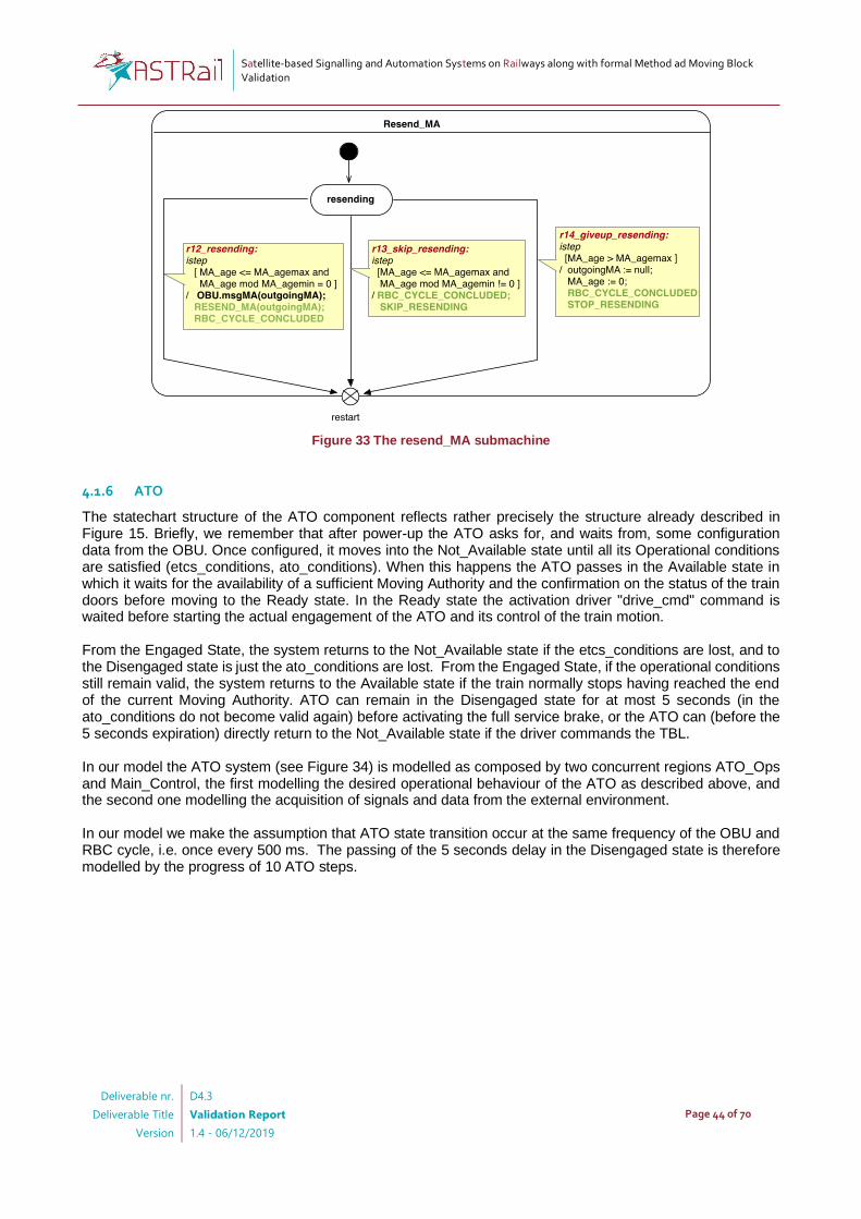
Satellite-based Signalling and Automation Systems on Railways along with formal Method ad Moving Block Validation
Deliverable nr.
Deliverable Title
Version
D4.3
Validation Report
1.4 - 06/12/2019
Page 44 of 70
Figure 33 The resend_MA submachine
4.1.6 ATO
The statechart structure of the ATO component reflects rather precisely the structure already described in Figure 15. Briefly, we remember that after power-up the ATO asks for, and waits from, some configuration data from the OBU. Once configured, it moves into the Not_Available state until all its Operational conditions are satisfied (etcs_conditions, ato_conditions). When this happens the ATO passes in the Available state in which it waits for the availability of a sufficient Moving Authority and the confirmation on the status of the train doors before moving to the Ready state. In the Ready state the activation driver "drive_cmd" command is waited before starting the actual engagement of the ATO and its control of the train motion. From the Engaged State, the system returns to the Not_Available state if the etcs_conditions are lost, and to the Disengaged state is just the ato_conditions are lost. From the Engaged State, if the operational conditions still remain valid, the system returns to the Available state if the train normally stops having reached the end of the current Moving Authority. ATO can remain in the Disengaged state for at most 5 seconds (in the ato_conditions do not become valid again) before activating the full service brake, or the ATO can (before the 5 seconds expiration) directly return to the Not_Available state if the driver commands the TBL. In our model the ATO system (see Figure 34) is modelled as composed by two concurrent regions ATO_Ops and Main_Control, the first modelling the desired operational behaviour of the ATO as described above, and the second one modelling the acquisition of signals and data from the external environment. In our model we make the assumption that ATO state transition occur at the same frequency of the OBU and RBC cycle, i.e. once every 500 ms. The passing of the 5 seconds delay in the Disengaged state is therefore modelled by the progress of 10 ATO steps.

Satellite-based Signalling and Automation Systems on Railways along with formal Method ad Moving Block Validation
Deliverable nr.
Deliverable Title
Version
D4.3
Validation Report
1.4 - 06/12/2019
Page 45 of 70
Figure 34 The ATO State Machine
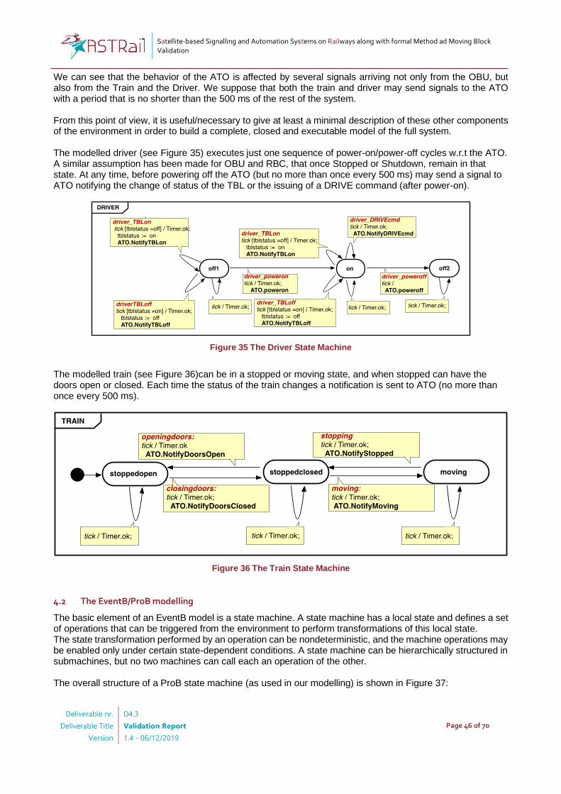
Satellite-based Signalling and Automation Systems on Railways along with formal Method ad Moving Block Validation
Deliverable nr.
Deliverable Title
Version
D4.3
Validation Report
1.4 - 06/12/2019
Page 46 of 70
We can see that the behavior of the ATO is affected by several signals arriving not only from the OBU, but also from the Train and the Driver. We suppose that both the train and driver may send signals to the ATO with a period that is no shorter than the 500 ms of the rest of the system. From this point of view, it is useful/necessary to give at least a minimal description of these other components of the environment in order to build a complete, closed and executable model of the full system. The modelled driver (see Figure 35) executes just one sequence of power-on/power-off cycles w.r.t the ATO. A similar assumption has been made for OBU and RBC, that once Stopped or Shutdown, remain in that state. At any time, before powering off the ATO (but no more than once every 500 ms) may send a signal to ATO notifying the change of status of the TBL or the issuing of a DRIVE command (after power-on).
Figure 35 The Driver State Machine
The modelled train (see Figure 36)can be in a stopped or moving state, and when stopped can have the doors open or closed. Each time the status of the train changes a notification is sent to ATO (no more than once every 500 ms).
Figure 36 The Train State Machine
4.2 The EventB/ProB modelling
The basic element of an EventB model is a state machine. A state machine has a local state and defines a set of operations that can be triggered from the environment to perform transformations of this local state. The state transformation performed by an operation can be nondeterministic, and the machine operations may be enabled only under certain state-dependent conditions. A state machine can be hierarchically structured in submachines, but no two machines can call each an operation of the other. The overall structure of a ProB state machine (as used in our modelling) is shown in Figure 37:
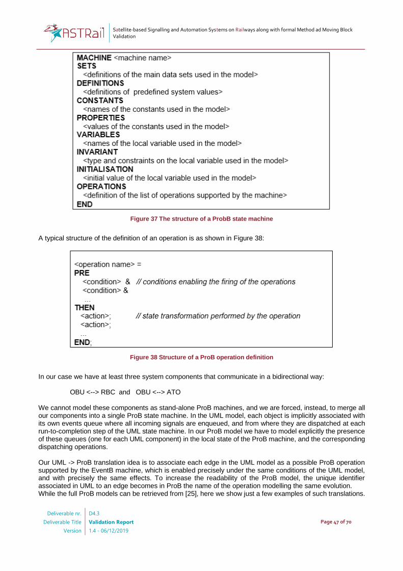
Satellite-based Signalling and Automation Systems on Railways along with formal Method ad Moving Block Validation
Deliverable nr.
Deliverable Title
Version
D4.3
Validation Report
1.4 - 06/12/2019
Page 47 of 70
Figure 37 The structure of a ProbB state machine
A typical structure of the definition of an operation is as shown in Figure 38:
Figure 38 Structure of a ProB operation definition
In our case we have at least three system components that communicate in a bidirectional way:
OBU <--> RBC and OBU <--> ATO We cannot model these components as stand-alone ProB machines, and we are forced, instead, to merge all our components into a single ProB state machine. In the UML model, each object is implicitly associated with its own events queue where all incoming signals are enqueued, and from where they are dispatched at each run-to-completion step of the UML state machine. In our ProB model we have to model explicitly the presence of these queues (one for each UML component) in the local state of the ProB machine, and the corresponding dispatching operations. Our UML -> ProB translation idea is to associate each edge in the UML model as a possible ProB operation supported by the EventB machine, which is enabled precisely under the same conditions of the UML model, and with precisely the same effects. To increase the readability of the ProB model, the unique identifier associated in UML to an edge becomes in ProB the name of the operation modelling the same evolution. While the full ProB models can be retrieved from [25], here we show just a few examples of such translations.

Satellite-based Signalling and Automation Systems on Railways along with formal Method ad Moving Block Validation
Deliverable nr.
Deliverable Title
Version
D4.3
Validation Report
1.4 - 06/12/2019
Page 48 of 70
Let us consider the case shown in Figure 39 of UML State Machine evolution taken from the model of the OBU behaviour:
Figure 39 An OBU completion transition
Supposing that we will have in our ProB machine the set of initial definitions shown Figure 40:
Figure 40 Initial part of ProB machine definition
Then, the list of operations will include the definition of the o3_position_ok operation as shown in Figure 41:
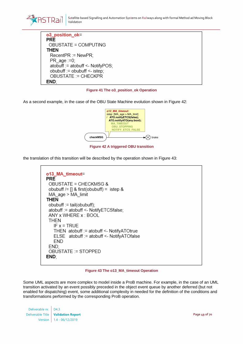
Satellite-based Signalling and Automation Systems on Railways along with formal Method ad Moving Block Validation
Deliverable nr.
Deliverable Title
Version
D4.3
Validation Report
1.4 - 06/12/2019
Page 49 of 70
Figure 41 The o3_position_ok Operation
As a second example, in the case of the OBU State Machine evolution shown in Figure 42:
Figure 42 A triggered OBU transition
the translation of this transition will be described by the operation shown in Figure 43:
Figure 43 The o13_MA_timeout Operation
Some UML aspects are more complex to model inside a ProB machine. For example, in the case of an UML transition activated by an event possibly preceded in the object event queue by another deferred (but not enabled for dispatching) event, some additional complexity in needed for the definition of the conditions and transformations performed by the corresponding ProB operation.

Satellite-based Signalling and Automation Systems on Railways along with formal Method ad Moving Block Validation
Deliverable nr.
Deliverable Title
Version
D4.3
Validation Report
1.4 - 06/12/2019
Page 50 of 70
4.3 The EventB/ProB verification
Once the full model of the integrated ATO-OBU-RBC system is modelled in ProB, the observation and monitoring of its evolutions become quite easy and friendly. The Figure 44 shows the way in which (one of) the ProB GUI allows to monitor and animate the system evolutions.
Figure 44 The ProB simulation GUI
We are mainly interested with the LTL verification approach because this is the most useful for the expression of temporal event-based behavioural properties. It is worth noticing that the LTL logic supported by ProB allows the specification not only of basic state predicates involving the values of the machine local variables (e.g. {OBUSTATE /= STOPPED}), but also the
specification of properties referring the operation names triggering the system evolutions (e.g.
Values of the State Machine variables
at the current statePossible evolutions from
the current state
Prob model
Sequence of steps performed
to reach the current state
Navigation buttons
for moving in the history

Satellite-based Signalling and Automation Systems on Railways along with formal Method ad Moving Block Validation
Deliverable nr.
Deliverable Title
Version
D4.3
Validation Report
1.4 - 06/12/2019
Page 51 of 70
[o1_startcycle]). ProB supports a rich set of temporal operators, inclusing the classical X, F, G, U, W, R,
that can be arbitrarily composed (for more detail see10). Here we only hint a few examples that reflect most of our usages: G (<subformula1> => <subformula2> )
Starting from the curent state of the path, whenver <subformula1> holds, also <subformula2> holds.
F (<subformula>)
Starting from the curent state of the path, eventually <subformula1> holds.
<subformula1> U <subformula2>
Starting from the curent state of the path, <subformula1> holds until <subformula2> eventually holds in
the future.
<subformula1> W <subformula2>
Starting from the curent state of the path, <subformula1> holds until <subformula2> possibly holds in the
future (but if <subformula2> never holds in the path, it is acceptable that <subformula1> holds forever).
X <subformula>
Starting from the curent state of the path, <subformula1> must immediately hold after one step.
When verifying a property that is internal to a subsystem, e.g. one of the "Moving Block System Requirements" described in Annex A – System Requirements, it would be overkilling to attempt its verification in the full integrated system including the actual ATO, when the presence of such subsystem is actually not relevant. It is instead convenient to the prove these properties taking into account a reduced subsystem in which some components, if possible, are removed or replaced by a smaller, and more abstract models. For example, while proving the Moving Block Requirements we might simply omit the presence of the ATO, DRIVER and TRAIN components, and when proving properties of the ATO component we might simply omit the presence of RBC and replace the OBU system with a simpler abstract model describing its abstract behaviour. These simplifications actually allow to make the verification feasible reducing the magnitude of the number of states to be analysed from billions of to a few hundreds of thousands (or just a few millions) states. Unfortunately, these "abstract replacement" of subsystems cannot be done automatically in the ProB/EventB setting but must be performed by hand, taking the responsibility to find the optimal choice in terms of state-space reduction and preservation of the system properties of interest11.
4.3.1 Moving Block verification
The verification of the Moving Block subsystem can be performed by just taking into account the OBU and RBC components. The resulting ProB state machine is the one described in the file "PROB-MB-alone-v13.mch" (See [25]). We show here only some of verifications that can be performed to show how the functional requirements are actually reflected within our model, and possibly encoded and verified in terms of ProB LTL logics. It is beyond the purpose of this deliverable to show in detail how all the requirements stated in Annex A are handled by our modelling and verification. In the following we will show also a few examples of how some other requirements couldn't instead be formally proved on the current system, mostly because they may refer to aspects intentionally not modelled or modelled in an abstract way. Then, we will focus on those requirements that can be proved, instead.
10 https://www3.hhu.de/stups/prob/index.php/LTL_Model_Checking 11 We did not investigate in detail the Prob/ EventB machine refinement features, that might help to this purpose
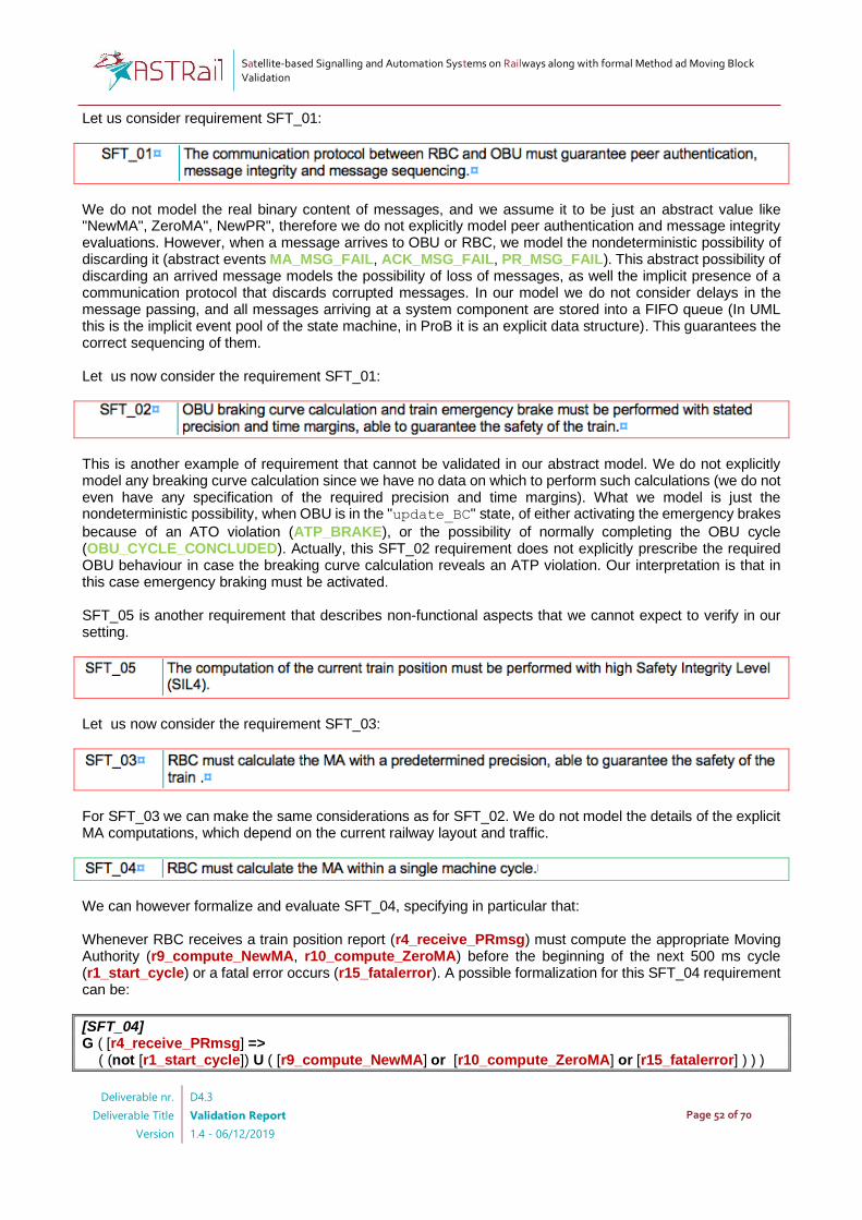
Satellite-based Signalling and Automation Systems on Railways along with formal Method ad Moving Block Validation
Deliverable nr.
Deliverable Title
Version
D4.3
Validation Report
1.4 - 06/12/2019
Page 52 of 70
Let us consider requirement SFT_01:
We do not model the real binary content of messages, and we assume it to be just an abstract value like "NewMA", ZeroMA", NewPR", therefore we do not explicitly model peer authentication and message integrity evaluations. However, when a message arrives to OBU or RBC, we model the nondeterministic possibility of discarding it (abstract events MA_MSG_FAIL, ACK_MSG_FAIL, PR_MSG_FAIL). This abstract possibility of discarding an arrived message models the possibility of loss of messages, as well the implicit presence of a communication protocol that discards corrupted messages. In our model we do not consider delays in the message passing, and all messages arriving at a system component are stored into a FIFO queue (In UML this is the implicit event pool of the state machine, in ProB it is an explicit data structure). This guarantees the correct sequencing of them. Let us now consider the requirement SFT_01:
This is another example of requirement that cannot be validated in our abstract model. We do not explicitly model any breaking curve calculation since we have no data on which to perform such calculations (we do not even have any specification of the required precision and time margins). What we model is just the nondeterministic possibility, when OBU is in the "update_BC" state, of either activating the emergency brakes
because of an ATO violation (ATP_BRAKE), or the possibility of normally completing the OBU cycle (OBU_CYCLE_CONCLUDED). Actually, this SFT_02 requirement does not explicitly prescribe the required OBU behaviour in case the breaking curve calculation reveals an ATP violation. Our interpretation is that in this case emergency braking must be activated. SFT_05 is another requirement that describes non-functional aspects that we cannot expect to verify in our setting.
Let us now consider the requirement SFT_03:
For SFT_03 we can make the same considerations as for SFT_02. We do not model the details of the explicit MA computations, which depend on the current railway layout and traffic.
We can however formalize and evaluate SFT_04, specifying in particular that: Whenever RBC receives a train position report (r4_receive_PRmsg) must compute the appropriate Moving Authority (r9_compute_NewMA, r10_compute_ZeroMA) before the beginning of the next 500 ms cycle (r1_start_cycle) or a fatal error occurs (r15_fatalerror). A possible formalization for this SFT_04 requirement can be:
[SFT_04] G ( [r4_receive_PRmsg] => ( (not [r1_start_cycle]) U ( [r9_compute_NewMA] or [r10_compute_ZeroMA] or [r15_fatalerror] ) ) )
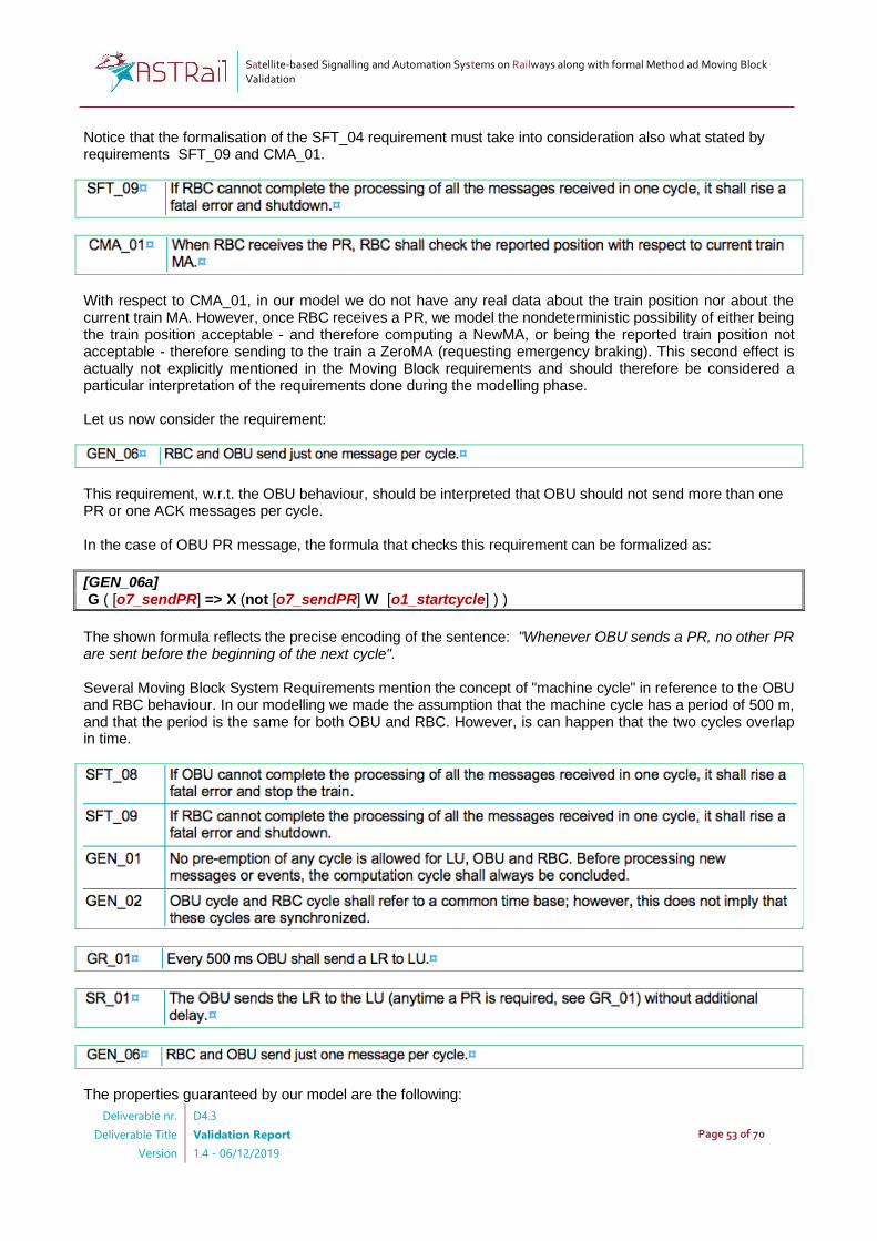
Satellite-based Signalling and Automation Systems on Railways along with formal Method ad Moving Block Validation
Deliverable nr.
Deliverable Title
Version
D4.3
Validation Report
1.4 - 06/12/2019
Page 53 of 70
Notice that the formalisation of the SFT_04 requirement must take into consideration also what stated by requirements SFT_09 and CMA_01.
With respect to CMA_01, in our model we do not have any real data about the train position nor about the current train MA. However, once RBC receives a PR, we model the nondeterministic possibility of either being the train position acceptable - and therefore computing a NewMA, or being the reported train position not acceptable - therefore sending to the train a ZeroMA (requesting emergency braking). This second effect is actually not explicitly mentioned in the Moving Block requirements and should therefore be considered a particular interpretation of the requirements done during the modelling phase. Let us now consider the requirement:
This requirement, w.r.t. the OBU behaviour, should be interpreted that OBU should not send more than one PR or one ACK messages per cycle. In the case of OBU PR message, the formula that checks this requirement can be formalized as:
[GEN_06a] G ( [o7_sendPR] => X (not [o7_sendPR] W [o1_startcycle] ) )
The shown formula reflects the precise encoding of the sentence: "Whenever OBU sends a PR, no other PR are sent before the beginning of the next cycle". Several Moving Block System Requirements mention the concept of "machine cycle" in reference to the OBU and RBC behaviour. In our modelling we made the assumption that the machine cycle has a period of 500 m, and that the period is the same for both OBU and RBC. However, is can happen that the two cycles overlap in time.
The properties guaranteed by our model are the following:
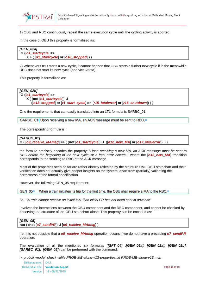
Satellite-based Signalling and Automation Systems on Railways along with formal Method ad Moving Block Validation
Deliverable nr.
Deliverable Title
Version
D4.3
Validation Report
1.4 - 06/12/2019
Page 54 of 70
1) OBU and RBC continuously repeat the same execution cycle until the cycling activity is aborted. In the case of OBU this property is formalized as:
[GEN_02a] G ([o1_startcycle] => X F ( [o1_startcycle] or [o18_stopped] ) )
2) Whenever OBU starts a new cycle, it cannot happen that OBU starts a further new cycle if in the meanwhile RBC does not start its new cycle (and vice-versa). This property is formalized as:
[GEN_02b] G ([o1_startcycle] => X ( (not [o1_startcycle]) U ([o18_stopped] or [r1_start_cycle] or [r15_fatalerror] or [r16_shutdown]) ) )
One the requirements that can easily translated into an LTL formula is SARBC_01:
The corresponding formula is:
[SARBC_01] G ( [o9_receive_MAmsg] => ( (not [o1_startcycle]) U ([o12_new_MA] or [o17_fatalerror]) ) )
the formula precisely encodes the property: "Upon receiving a new MA, an ACK message must be sent to RBC before the beginning of the next cycle, or a fatal error occurs.", where the [o12_new_MA] transition corresponds to the sending to RBC of the ACK message. Most of the properties seen so far are rather directly reflected by the structure UML OBU statechart and their verification does not actually give deeper insights on the system, apart from (partially) validating the correctness of the formal specification. However, the following GEN_05 requirement:
i.e. "A train cannot receive an initial MA, if an initial PR has not been sent in advance" Involves the interactions between the OBU component and the RBC component, and cannot be checked by observing the structure of the OBU statechart alone. This property can be encoded as:
[GEN_05] not ( (not [o7_sendPR]) U [o9_receive_MAmsg] )
I.e. It is not possible that a o9_receive_MAmsg operation occurs if we do not have a preceding o7_sendPR operation. The evaluation of all the mentioned six formulas ([SFT_04] ,[GEN_06a], [GEN_02a], [GEN_02b], [SARBC_01], [GEN_05]) can be performed with the command:
> probcli -model_check -ltlfile PROB-MB-alone-v13-properties.txt PROB-MB-alone-v13.mch

Satellite-based Signalling and Automation Systems on Railways along with formal Method ad Moving Block Validation
Deliverable nr.
Deliverable Title
Version
D4.3
Validation Report
1.4 - 06/12/2019
Page 55 of 70
The whole statespace of the MB model (361119 states) is computed in about 10 minutes, and the validity of all the formulas is verified in approximately one additional minute12.
4.3.2 ATO verification
The verification of the ATO properties can be performed without taking into account the RBC component, but it requires at least an abstract version of the OBU. An example of such state machine is described in the file "PROB-ATO-alone-v13.mch" (see [25]). In this model, we have used our full ATO definition, plus an abstract version of the environment composed by the TRAIN, the DRIVER, and an abstract version of OBU. We have already shown in Figure 35, Figure 33 the models of the TRAIN and DRIVER components, and here we suppose that the abstract (reduced) OBU component is as shown in Figure 45.
Figure 45 Abstract (reduced) OBU State Machine
I.e. Our abstract OBU is a cycling activity with the same period or the actual OBU. It can continue its cycling until it moves into a stopped state. While cycling, it replies to any configuration request from the ATO, and at each step may notify to ATO the train position and a new Moving Authority, while always notifies the ETCS conditions as true, and ATO conditions that can no deterministically have a true/false value. When moving into the stopped state, and when remaining in this state, OBU notifies to ATO the ETCS conditions as false, while the ATO conditions can still nondeterministic ally have a true/false value. With this environment, we can verify many of ATO requirements, like:
Whose ProB LTL encoding becomes:
[ATO_02] G (( [a26_power_off] or [a29_power_off] ) => X G {ATOSTATE = END_NOPOWER} )
Let us now consider the requirement ATO_04:
12 Computations performed on Apple MacBook Air with 8G RAM

Satellite-based Signalling and Automation Systems on Railways along with formal Method ad Moving Block Validation
Deliverable nr.
Deliverable Title
Version
D4.3
Validation Report
1.4 - 06/12/2019
Page 56 of 70
the correct translation of the above requirement is for example the following formula:
[ATO_04] G ( {ATOSTATE = WAIT_CONFIG} => ( {ATOSTATE = WAIT_CONFIG} W ([a4_config_ok] or [a26_power_off] or [a27_ato_fault]) ) )
I.e. ATO remains in WAIT_CONFIG until it receives the configuation data, unless powered-off by the driver, or unless a fault occurs. Notice the use of the Weak Until logical operator (W) because the conditions on the right side of the until might in principle also never occur. In particular, it the train stops before providing the ATO configuration it will nevermore reply to the ATO configuration request (actually this is one of the interpretations of the requirements introduced in our model), and if the driver does not poweroff and no fault occur, ATO will remain in the WAIT_CONFIG state. The translation of the requirement ATO_07 follows the same line of ATO_08.
The translation of ATO_07 becomes:
[ATO_07] G ( {ATOSTATE = NOT_AVAILABLE} => ( {ATOSTATE = NOT_AVAILABLE} W ( ( {etcs_conditions = TRUE} & {ato_conditions = TRUE} ) or ( [a26_power_off] or [a27_ato_fault] ) ) ) )
Again, it is true that ATO remains in the NOT_AVAILABLE state, as long no poweroff of fault occur. If we consider noe the requirement ATO_08:
Also in this case the implicit assumptions behind the above statement (i.e. provided that the operational conditions remain true, and no faults nor poweroff occur) must be made explicit in order to have a valid formula, that becomes:
[ATO_08] G ( {ATOSTATE = AVAILABLE} => ( {ATOSTATE = AVAILABLE} W ( ( { doors_closed = TRUE} & { first_MA_received =TRUE} & {etcs_conditions = TRUE} & {ato_conditions = TRUE} ) or [a8_op_conds_lost] or [a4_config_ok] or [a26_power_off] or [a27_ato_fault] ) ) )
Beyond verifying the explicitly required properties described by the requirements (often directly reflected by the statechart structure), it is useful to analyse further properties, maybe not directly expressed by the requirements) that might however help in getting e deeper view of the system behaviour. Let us consider, for example, the property: "It cannot happen that the train doors are open when ATO has full_service_brake activated" whose translation is the following formula:
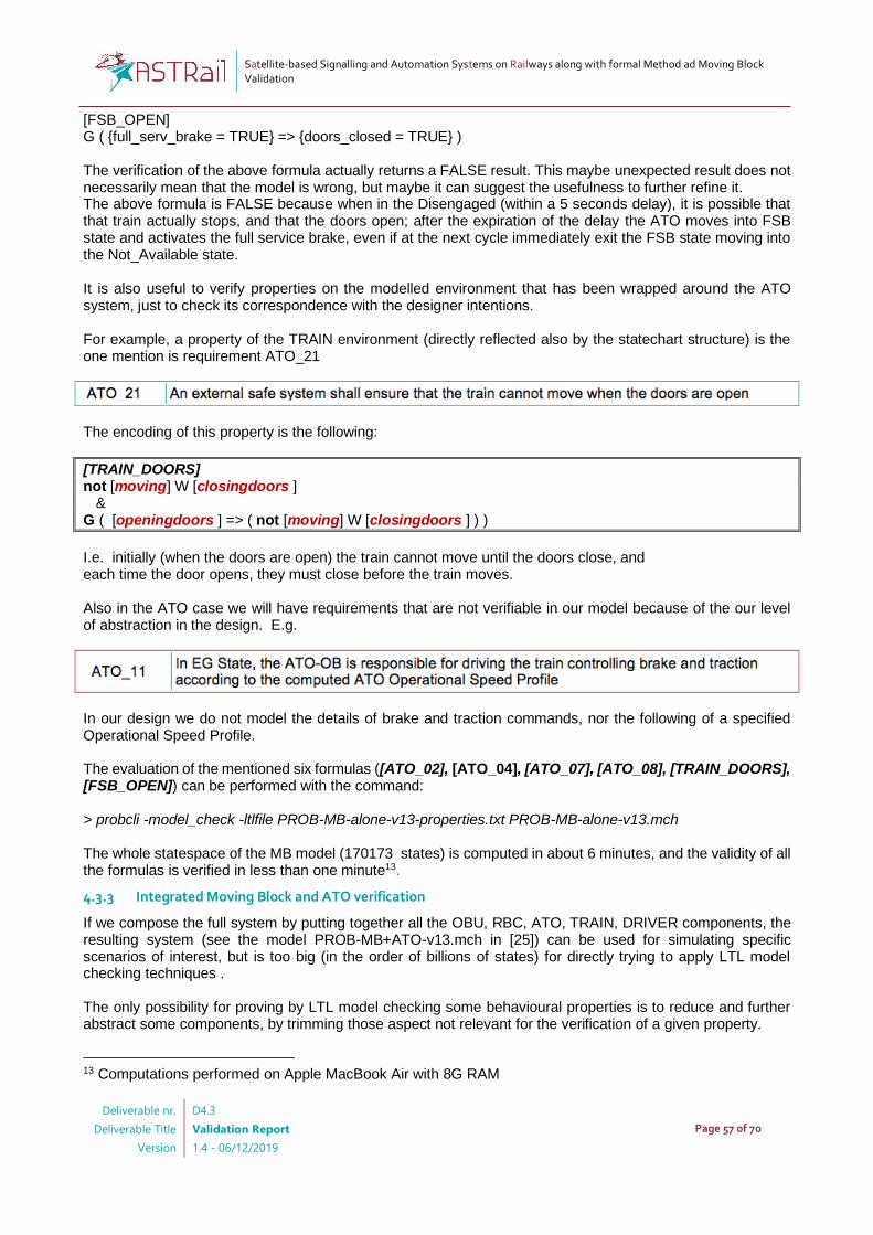
Satellite-based Signalling and Automation Systems on Railways along with formal Method ad Moving Block Validation
Deliverable nr.
Deliverable Title
Version
D4.3
Validation Report
1.4 - 06/12/2019
Page 57 of 70
[FSB_OPEN] G ( {full_serv_brake = TRUE} => {doors_closed = TRUE} ) The verification of the above formula actually returns a FALSE result. This maybe unexpected result does not necessarily mean that the model is wrong, but maybe it can suggest the usefulness to further refine it. The above formula is FALSE because when in the Disengaged (within a 5 seconds delay), it is possible that that train actually stops, and that the doors open; after the expiration of the delay the ATO moves into FSB state and activates the full service brake, even if at the next cycle immediately exit the FSB state moving into the Not_Available state. It is also useful to verify properties on the modelled environment that has been wrapped around the ATO system, just to check its correspondence with the designer intentions. For example, a property of the TRAIN environment (directly reflected also by the statechart structure) is the one mention is requirement ATO_21
The encoding of this property is the following:
[TRAIN_DOORS] not [moving] W [closingdoors ] & G ( [openingdoors ] => ( not [moving] W [closingdoors ] ) )
I.e. initially (when the doors are open) the train cannot move until the doors close, and each time the door opens, they must close before the train moves. Also in the ATO case we will have requirements that are not verifiable in our model because of the our level of abstraction in the design. E.g.
In our design we do not model the details of brake and traction commands, nor the following of a specified Operational Speed Profile. The evaluation of the mentioned six formulas ([ATO_02], [ATO_04], [ATO_07], [ATO_08], [TRAIN_DOORS], [FSB_OPEN]) can be performed with the command: > probcli -model_check -ltlfile PROB-MB-alone-v13-properties.txt PROB-MB-alone-v13.mch The whole statespace of the MB model (170173 states) is computed in about 6 minutes, and the validity of all the formulas is verified in less than one minute13.
4.3.3 Integrated Moving Block and ATO verification
If we compose the full system by putting together all the OBU, RBC, ATO, TRAIN, DRIVER components, the resulting system (see the model PROB-MB+ATO-v13.mch in [25]) can be used for simulating specific scenarios of interest, but is too big (in the order of billions of states) for directly trying to apply LTL model checking techniques . The only possibility for proving by LTL model checking some behavioural properties is to reduce and further abstract some components, by trimming those aspect not relevant for the verification of a given property.
13 Computations performed on Apple MacBook Air with 8G RAM
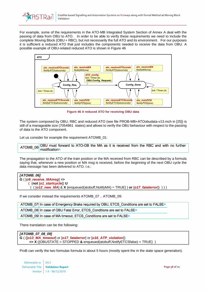
Satellite-based Signalling and Automation Systems on Railways along with formal Method ad Moving Block Validation
Deliverable nr.
Deliverable Title
Version
D4.3
Validation Report
1.4 - 06/12/2019
Page 58 of 70
For example, some of the requirements in the ATO-MB Integrated System Section of Annex A deal with the passing of data from OBU to ATO. In order to be able to verify these requirements we need to include the complete Moving Block (OBU + RBC), but not necessarily the full ATO and its environment. For our purposes it is sufficient a reduced ATO that just includes the components needed to receive the data from OBU. A possible example of OBU-related reduced ATO is shown in Figure 46
Figure 46 A reduced ATO for receiving OBU data
The system composed by OBU, RBC and reduced ATO (see file PROB-MB+ATOobudata-v13.mch in [25]) is still of a manageable size (7054861 states) and allows to verify the OBU behaviour with respect to the passing of data to the ATO component. Let us consider for example the requirement ATOMB_01:
The propagation to the ATO of the train position or the MA received from RBC can be described by a formula saying that, whenever a new position or MA msg is received, before the beginning of the next OBU cycle the data message has been delivered to ATO. I.e.:
[ATOMB_06] G ( [o9_receive_MAmsg] => ( (not [o1_startcycle]) U ( ( [o12_new_MA] & X {enqueued(atobuff,NotifyMA) = TRUE} ) or [o17_fatalerror]) ) ) )
If we consider instead the requirements ATOMB_07 .. ATOMB_09:
There translation can be the following:
[ATOMB_07_08_09] G ( ([o13_MA_timeout] or [o17_fatalerror] or [o16_ATP_violation]) => X ({OBUSTATE = STOPPED & enqueued(atobuff,NotifyETCSfalse) = TRUE} )
ProB can verify the two formulas formula in about 5 hours (mostly spent the in the state space generation).
Satellite-based Signalling and Automation Systems on Railways along with formal Method ad Moving Block Validation
Deliverable nr.
Deliverable Title
Version
D4.3
Validation Report
1.4 - 06/12/2019
Page 59 of 70
The requirements ATOMB_03, ATOMB_04, ATOMB_05 instead describe the possible ATO-driver interactions and can be verified on the same model used for the analysis of the internal ATO requirements (see file ATO-alone-v13.mch in [25]), which already includes both the ATO and DRIVER models.
The property the something must have the possibility to happen can be verified in the LTL case by proving that the converse in not true. I.e. that it is not true that something does not never happen. The formulas corresponding to the above requirements are therefore the following:
[ATOMB_03] ( G (not [driver_poweron] or not X {enqueued(atobuff, poweron) = TRUE}) ) [ATOMB_04] ( G (not [driver_poweroff] or not X {enqueued(atobuff, poweroff) = TRUE}) ) [ATOMB_05] ( G (not [driver_DRIVEcmd] or not X {enqueued(atobuff, NotifyDRIVEcmd) = TRUE}) ) [ATOMB_06] ( G (not [driver_TBLon] or not X {enqueued(atobuff, NotifyTBLon) = TRUE}) ) [ATOMB_06] ( G (not [driver_TBLoff] or not X {enqueued(atobuff, NotifyTBLoff) = TRUE}) )
The above formulas can be verified on a very small system composed by a reduced version of ATO and the DRIVER, and for each formula the counter example is found almost instantaneously.
4.4 Observations
4.4.1 Correctness of the system design
The overall formal modelling and verification process requires a not trivial amount of time and effort. It is therefore reasonable to ask whether, in the end, we could trust the resulting design to be correct. If for "correct" we mean "something that will surely not need to be fixed at a later time", then we can hardly guarantee this desire. Indeed, we have found in our models small mistakes which needed to be fixed even after having built, animated, and verified the requirements on models. The problem is that the system requirements rarely describe completely the actually intended system behaviour (especially from the point of view of liveness properties). From this point of view the animation of the formal model, and the verification of further expected properties might help in increasing the confidence of the robustness of the design and the completeness of the requirements. If for "correct" we mean that the system simply "satisfies all its stated requirements" the answer can hopefully be positive (w.r.t. the set of actually verified requirements), provided that the whole verification process has been carried out without making mistakes. And this leads us to the following points.
4.4.2 Correctness of the ProB translation
The first step of our verification process consists in the formalisation in terms of a ProB machine of the original UML design. We have two potentially weak points from this point of view. The first one is related to the UML notation and its semantics, that might be misunderstood by the designer or by the person performing the translation. This is an issue related to the intrinsic ambiguities of UML that we will not discuss further. The second weak point is the possibility of having made mistakes during the translation process.

Satellite-based Signalling and Automation Systems on Railways along with formal Method ad Moving Block Validation
Deliverable nr.
Deliverable Title
Version
D4.3
Validation Report
1.4 - 06/12/2019
Page 60 of 70
In our case the translation performed is rather mechanical and not difficult to check (given the simple structure of our UML models), moreover the formal animation and verification of the ProB specification surely helps greatly in detecting possible translation mistakes (and indeed this happened many times in our activity). In principle, if we could mechanically save the LTS semantics of the UML design, and the LTS semantics of the ProB specification, we might also formally verify the correctness of the translation result. This approach has been experimented (in the case of the Moving Block model) using the UMC tool14 for saving the LTS semantics of the UML design, using the ProB functionalities to save the statespace and using CADP15 to verify the equivalence of the two models. This activity actually helped in discovering some initial mistakes during the first experimentations of the UML -> ProB translation.
4.4.3 Correctness of the LTL formulas
In our verification process we have translated most of the system requirements into LTL formulas and verified them on the resulting Prob model. However, the LTL encoding of a given property is another activity "at risk". The meaning of the temporal logic formulas is not always easy to understand, even for people well experienced, and with a solid background on the subject. The formulas resulting from our verification process have almost always been the final result of a sequence of trials and errors, where the errors were identified at each step either in the UML design, or in the ProB translation, or in the formula. ProB provides several verification/analysis methods that go beyond the verification of LTL or CTL formulas The possibility of encoding the same properties in several ways (e.g. using LTL versus CTL, using state-based versus operation-based properties) might allow to exploit a certain degree of diversity in encoding the properties that might be of help.
4.4.4 Correctness of the ProB tool
It would be desirable that the tool itself were certified and validated for a high lever of integrity. However requiring a SIL4 level of integrity is definitely overkilling (since we are not dealing with the final system validation and certification, but just its high level speciation). Even if we cannot exclude the presence of errors in the Prob verification engine, the maturity of the tool and its relatively wide use probably allow us to consider this aspect the smallest of the problems mentioned so far.
4.4.5 Current limits of our approach
Efficiency of validation Model checking with the internal engine of ProB is not as efficient as other famous model checkers. During the design/early prototyping phase (as opposed to final validation) a fast response (in the order of few minutes max) by the verification is particularly useful. This relative weakness is highly reduced by the fact that ProB directly supports several different verification methods16 like:
- Consistency Checking - Constraint BasedChecking - Refinement Checking - LTL (and partially CTL) Model Checking - Symbolic Model Checking.
ProB also supports interfaces and plugins for the verification using other external model checkers like LTSmin and TLC. Last, but not least, ProB allows the saving of the full state-space in an open textual format. It becomes therefore possible to translate the ProB state-space into a standard notation of Labelled Transition Systems (using the .aut format), which in turn enables explicit, on the fly model checking with further advanced model checking tools like CADP, or MCRL2. Degree of competence required for mastering the tools In the case of Prob, the extreme richness of the tool in some sense risks to fight back. It allows so many different verification/ analysis approaches that it might become quite difficult to master the tool in all its aspects.
14 http://fmt.isti.cnr.it/umc 15 http://cadp.inria.fr 16 https://www3.hhu.de/stups/prob/index.php/User_Manual
Satellite-based Signalling and Automation Systems on Railways along with formal Method ad Moving Block Validation
Deliverable nr.
Deliverable Title
Version
D4.3
Validation Report
1.4 - 06/12/2019
Page 61 of 70
Graphical Specification Language Currently ProB lacks of a graphical / user friendly syntax (aspect inherited by EventB) for its machines. Many silly design errors (e.g. wrong target states, typically result of copy&paste operations) would become immediately visible in a graphical view of the system design. But on the contrary, graphical editing of a design is not always the most desirable approach for reasons of efficiency and documentation (a textual model representation is probably much more robust and easy to maintain). From this point of view, the definition of specific UML-B profiles and the support of bidirectional automatic translations might provide a possible solution. Vice versa, if we start from a graphical layout, the manual translation of it into a textual representation can easily be source of errors. These kinds of errors are very likely to be discovered in the subsequent verification phase, but certainly contribute in making more complex and lengthy the verification process. Interacting state machines In ProB, if two system components need to interact in a bidirectional way, we are forced to merge them into a single EventB state machine. This is a limit inherited by the EventB methodology that is needed in order to guarantee the preservation of the system invariants, but that is somewhat in contrast with the principles of design for systems of systems. Abstractions / Minimizations /Refinements In our verification process we had to manually build our "abstract versions" of system fragments in order to keep the size of the system into a verifiable limit, depending on the kind of property we intended to verify. UML formal background still lacks of theoretical support for refinements / minimisations and compositional verification of interacting state machines. ProB relies on EventB theoretical background for the support of refinements but, unfortunately, we did not have enough time and effort to investigate this possibility in detail. The possibility of "driving" a ProB machine from a CSP process might reveal to be another useful approach. Using other process-algebra based approaches and tools (e.g. CADP, MCRL2, FDR) this property dependent minimization activity could be done in an almost automatic way by exploiting equivalences, minimizations and congruence. Surely this is a line of research that might lead to great improvements of the state of art. UML limits The main weak aspect of UML is probably the incompleteness of its definition for a system of systems design; many implementations defined aspects related to statemachine-statemachine interactions are just implementation defined. Moreover, the official specification of UML statemachines notoriously contains many ambiguities that hinder its widespread use as a basis for formal modelling and verification. Finally, the state or art of freely available tools for design, animation and verification of UML models is currently not satisfactory. In our case we used UML unaware tools for the design of the statcharts (Omnigraffle on MacOS), and a custom, academically developed tool (UMC) for animation and verification of the systems. UMC however, being an academic prototype, does not have the degree of maturity needed for use in an industrial environment.

Satellite-based Signalling and Automation Systems on Railways along with formal Method ad Moving Block Validation
Deliverable nr.
Deliverable Title
Version
D4.3
Validation Report
1.4 - 06/12/2019
Page 62 of 70
5 Conclusions
The current deliverable presents the results of the final task of WP4 of the ASTRail project concerned with the validation of the choices of formal tools for the development of railway systems, based on the formal specification of the Moving-block system integrated with Automated Driving Technologies (ATO, Automatic Train Operation). In the deliverable, we have first illustrated the proposed formal process to be applied in the concept phase of the system development. The formal process consists of (1) a requirements elicitation and simulation phase; (2) a phase of mapping towards formal languages; (3) a phase of formal verification. In the first phase, the Simulink-Stateflow tool was applied to model and simulate the requirements provided by the railway experts, in order to produce a stable requirements specification document, together with an executable Simulink-Stateflow model of the integrated system including Moving-block and ATO. In the second phase, the requirements specification document and the Simulink-Stateflow model were used as input to produce a UML model, which focused on relevant abstraction of the system, and enabled a translation into the Event B formal language. In the third phase, the requirements produced were translated into logic formulae to formally verify the Event B model by means of the ProB tool. Most of the requirements could be verified by means of the tool. The final requirements specification is reported in Annex A – System Requirements. Instead, the Simulink-Stateflow models, together with their documentation in HTML format is available at [25]. In the same repository, we report the Event B models resulting from the activity, while UML models are reported as figures in the current deliverable (see Section 4.1). The summarised process demonstrates the feasibility of using formal methods in the concept phase of the development, and demonstrates the suitability of the choices made throughout the ASTRail project. Specifically, we observed that modelling and simulating early requirements enables the discovery of incomplete or too generic requirements, and it is an appropriate approach to provide an initial refinement and consolidation of the requirements. The graphical language used by Simulink-Stateflow could be interpreted by the domain experts with limited guidance, and was therefore an appropriate means to communicate between formal methods experts and domain experts. The usage of UML enabled the definition of an abstract specification oriented to model nondeterministic behaviour, which could not be modelled with Simulink-Stateflow. Further, translating the UML model into Event B enabled the discovery of incorrectness in the original UML model. Similarly, the translation of requirements into temporal logic formulas, and their verification by means of the ProB tool enabled further reflections on the modelled system, and further adjustments towards the consolidation of the requirements. Other relevant aspects should be considered when applying the proposed process. The time required for modelling in the different languages is not negligible, and high expertise is required for managing the different languages and tools. Furthermore, concerning the formal modelling and verification activity with ProB, it is important to notice that some abstraction choices needed to be manually made to enable efficient formal verification. These choices require expertise in formal modelling and verification, and human judgment is highly important. Overall, the process is not entirely supported by tools for what concern the translation from one language to another, including the translation of the requirements into temporal logic formulas. These observations indicate that, although the choices made within ASTRail can be considered valid for the scope of the project, the introduction of formal modelling and verification techniques in the railway process is not a fully automated process, as diverse expertise are required and the role of the expert subjects involved is paramount. Furthermore, especially in the concept phase, as the one we are concerned in this deliverable, the application of formal methods cannot be considered as a guarantee that requirements will not change in the future, when further refinement occurs towards the implementation. However, we argue that the usage of formal methods, in different forms and for different purposed, i.e., formal modelling, simulation, verification, certainly increases the confidence of the specified system requirements, and provides an increased guarantee that unexpected behaviour will be limited in future development phases. Further investigations about benefits of the adoptions formal methods in the complete development process of high safety-integrity-level products, especially targeted to railway market, could be a natural way to exploit and extend the results obtained in this work. An effective verification and validation activity (as required by shared rules, standards and best practices in the automotive and railway industries), needed to obtain the required product certification, is a complex and articulated process that involves the entire development phase, from the requirements definition to the deployment of the product itself. This process usually requires a lot of effort when compared to the entire development cycle. The introduction of formal methods in the entire flow could lead to better performance of the development process while improving the overall quality of the final

Satellite-based Signalling and Automation Systems on Railways along with formal Method ad Moving Block Validation
Deliverable nr.
Deliverable Title
Version
D4.3
Validation Report
1.4 - 06/12/2019
Page 63 of 70
product, even considering the maintenance phase. In this way, a cost benefit analysis, oriented to the entire life cycle cost of a product, could be addressed by further investigating the optimization role of formal methods, when put at the centre of the development process, considering the long-term scenario.
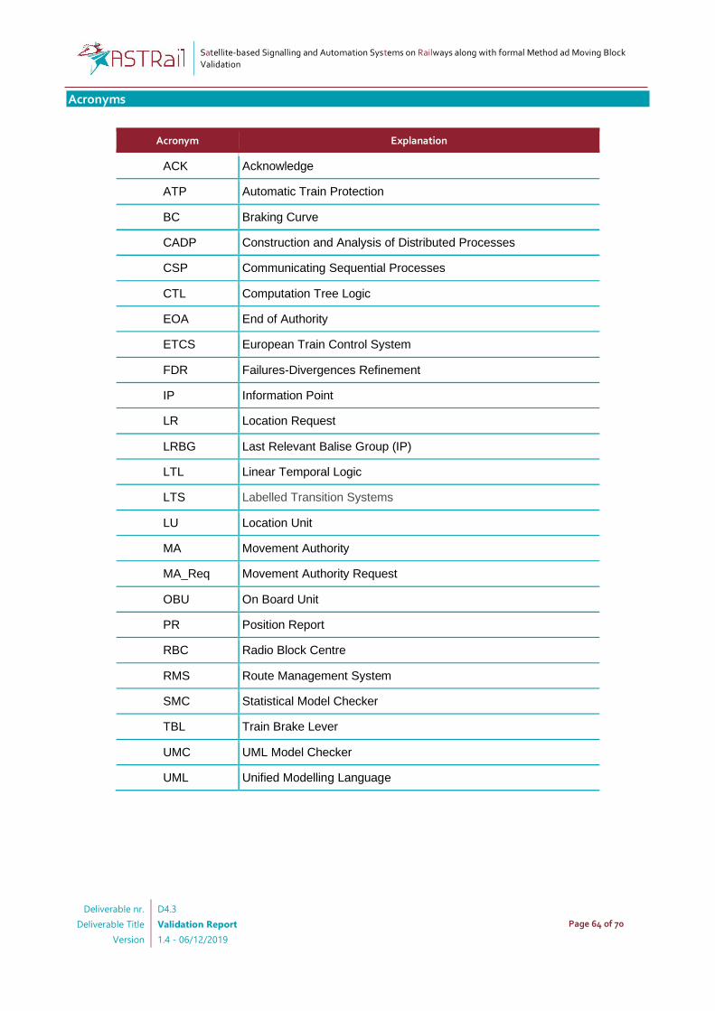
Satellite-based Signalling and Automation Systems on Railways along with formal Method ad Moving Block Validation
Deliverable nr.
Deliverable Title
Version
D4.3
Validation Report
1.4 - 06/12/2019
Page 64 of 70
Acronyms
Acronym Explanation
ACK Acknowledge
ATP Automatic Train Protection
BC Braking Curve
CADP Construction and Analysis of Distributed Processes
CSP Communicating Sequential Processes
CTL Computation Tree Logic
EOA End of Authority
ETCS European Train Control System
FDR Failures-Divergences Refinement
IP Information Point
LR Location Request
LRBG Last Relevant Balise Group (IP)
LTL Linear Temporal Logic
LTS Labelled Transition Systems
LU Location Unit
MA Movement Authority
MA_Req Movement Authority Request
OBU On Board Unit
PR Position Report
RBC Radio Block Centre
RMS Route Management System
SMC Statistical Model Checker
TBL Train Brake Lever
UMC UML Model Checker
UML Unified Modelling Language

Satellite-based Signalling and Automation Systems on Railways along with formal Method ad Moving Block Validation
Deliverable nr.
Deliverable Title
Version
D4.3
Validation Report
1.4 - 06/12/2019
Page 65 of 70
List of figures
Figure 1 Overview of the adopted formal process ................................................................................................................................................ 10
Figure 2 Simulink and Stateflow basic concepts .................................................................................................................................................... 13
Figure 3 Overview of the Moving-block system ..................................................................................................................................................... 14
Figure 4 Architecture of the Moving-block Simulink Model ............................................................................................................................. 16
Figure 5 Behaviour of the OBU component: High-level view ........................................................................................................................... 18
Figure 6 Behaviour of the OBU Component: GENERATE_LOCATION_REQUEST State ........................................................................... 18
Figure 7 Behaviour of the OBU Component: SEND_LOCATION_TO_RBC State ........................................................................................ 19
Figure 8 Behaviour of the OBU Component: RECEIVE_MA State .................................................................................................................... 19
Figure 9 Behaviour of the OBU Component: COMPUTE_BRAKING_CURVE State .................................................................................... 20
Figure 10 Behaviour of the LU Component .............................................................................................................................................................. 20
Figure 11 Behaviour of the RBC Component ........................................................................................................................................................... 21
Figure 12 Behaviour of the Train Component ......................................................................................................................................................... 22
Figure 13 Overview of the ATO in its context .......................................................................................................................................................... 22
Figure 14 Architecture of the ATO Model ................................................................................................................................................................. 23
Figure 15 Statechart representing the Operating Modes of the ATO ........................................................................................................... 25
Figure 16 Statechart representing the internal behaviour of the ATO Engaged State .......................................................................... 27
Figure 17 Statechart representing the Train model for the ATO ..................................................................................................................... 28
Figure 18 Multiple MA received and corresponding speed and space ........................................................................................................ 29
Figure 19 Brake and acceleration commands in relation to the train speed .............................................................................................. 30
Figure 20 Architecture of the model that integrates Moving-block system and ATO (Part 1) ........................................................... 31
Figure 21 Architecture of the model that integrates Moving-block system and ATO (Part 2) ........................................................... 32
Figure 22 Normal behaviour of the ATO in the integrated model ................................................................................................................. 33
Figure 23 Normal behaviour of the ATO in relation to acceleration, brake and speed ......................................................................... 33
Figure 24 Case of MA violation by the ATO ............................................................................................................................................................. 34
Figure 25 A statechart diagram fragment ................................................................................................................................................................. 37
Figure 26 OBU State Machine ........................................................................................................................................................................................ 39
Figure 27 The Compute_Position submachine ........................................................................................................................................................ 40
Figure 28 The Send_PR submachine ............................................................................................................................................................................ 40
Figure 29 The Handle_Msgs submachine .................................................................................................................................................................. 41
Figure 30 The RBC State Machine................................................................................................................................................................................. 42
Figure 31 The Receiving submachine .......................................................................................................................................................................... 43
Figure 32 The Compute_MA and Send_MA submachines ................................................................................................................................. 43
Figure 33 The resend_MA submachine ...................................................................................................................................................................... 44
Figure 34 The ATO State Machine ................................................................................................................................................................................ 45
Figure 35 The Driver State Machine............................................................................................................................................................................. 46
Figure 36 The Train State Machine ............................................................................................................................................................................... 46
Figure 37 The structure of a ProbB state machine ................................................................................................................................................ 47
Figure 38 Structure of a ProB operation definition ............................................................................................................................................... 47
Figure 39 An OBU completion transition ................................................................................................................................................................... 48
Figure 40 Initial part of ProB machine definition .................................................................................................................................................. 48
Figure 41 The o3_position_ok Operation................................................................................................................................................................... 49
Figure 42 A triggered OBU transition.......................................................................................................................................................................... 49
Figure 43 The o13_MA_timeout Operation .............................................................................................................................................................. 49
Figure 44 The ProB simulation GUI .............................................................................................................................................................................. 50
Figure 45 Abstract (reduced) OBU State Machine ................................................................................................................................................. 55
Figure 46 A reduced ATO for receiving OBU data ................................................................................................................................................. 58
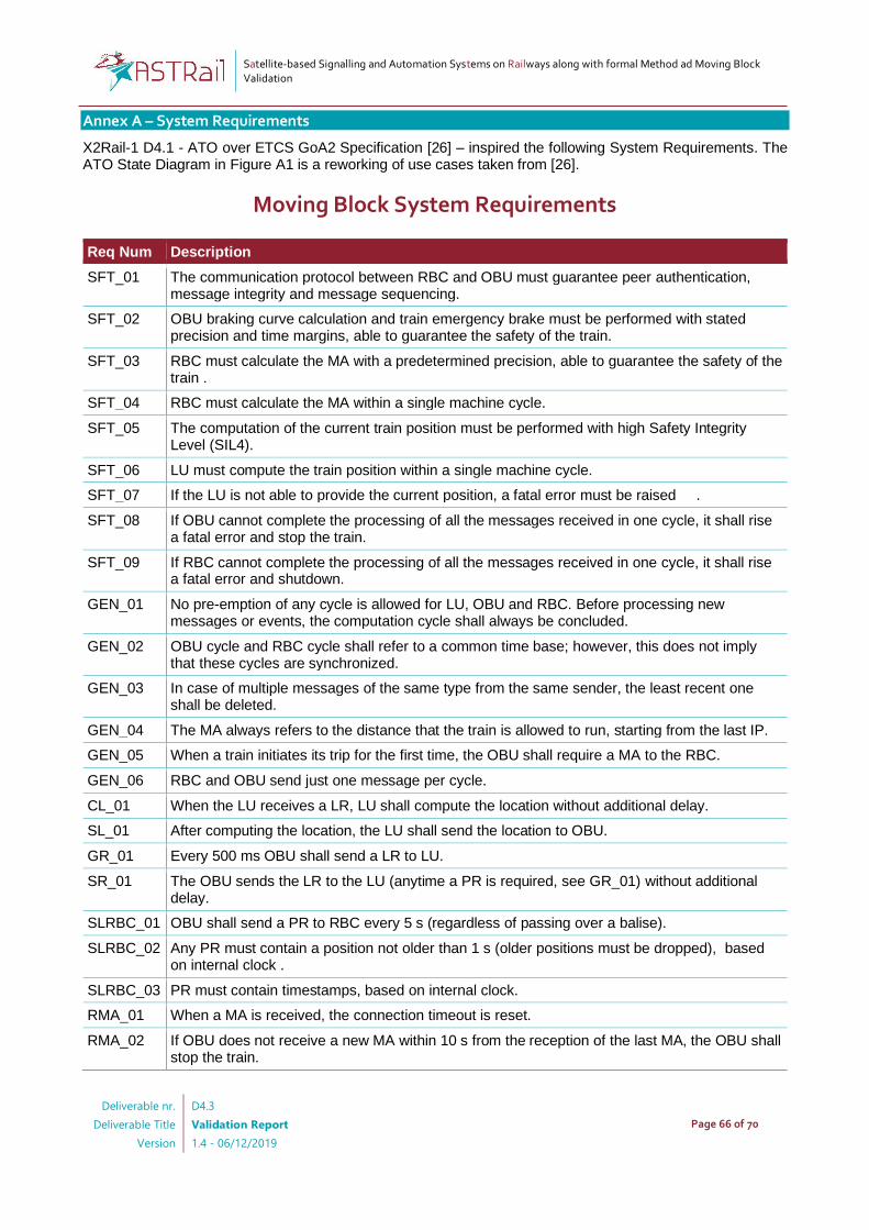
Satellite-based Signalling and Automation Systems on Railways along with formal Method ad Moving Block Validation
Deliverable nr.
Deliverable Title
Version
D4.3
Validation Report
1.4 - 06/12/2019
Page 66 of 70
Annex A – System Requirements
X2Rail-1 D4.1 - ATO over ETCS GoA2 Specification [26] – inspired the following System Requirements. The ATO State Diagram in Figure A1 is a reworking of use cases taken from [26].
Moving Block System Requirements
Req Num Description
SFT_01 The communication protocol between RBC and OBU must guarantee peer authentication, message integrity and message sequencing.
SFT_02 OBU braking curve calculation and train emergency brake must be performed with stated precision and time margins, able to guarantee the safety of the train.
SFT_03 RBC must calculate the MA with a predetermined precision, able to guarantee the safety of the train .
SFT_04 RBC must calculate the MA within a single machine cycle.
SFT_05 The computation of the current train position must be performed with high Safety Integrity Level (SIL4).
SFT_06 LU must compute the train position within a single machine cycle.
SFT_07 If the LU is not able to provide the current position, a fatal error must be raised .
SFT_08 If OBU cannot complete the processing of all the messages received in one cycle, it shall rise a fatal error and stop the train.
SFT_09 If RBC cannot complete the processing of all the messages received in one cycle, it shall rise a fatal error and shutdown.
GEN_01 No pre-emption of any cycle is allowed for LU, OBU and RBC. Before processing new messages or events, the computation cycle shall always be concluded.
GEN_02 OBU cycle and RBC cycle shall refer to a common time base; however, this does not imply that these cycles are synchronized.
GEN_03 In case of multiple messages of the same type from the same sender, the least recent one shall be deleted.
GEN_04 The MA always refers to the distance that the train is allowed to run, starting from the last IP.
GEN_05 When a train initiates its trip for the first time, the OBU shall require a MA to the RBC.
GEN_06 RBC and OBU send just one message per cycle.
CL_01 When the LU receives a LR, LU shall compute the location without additional delay.
SL_01 After computing the location, the LU shall send the location to OBU.
GR_01 Every 500 ms OBU shall send a LR to LU.
SR_01 The OBU sends the LR to the LU (anytime a PR is required, see GR_01) without additional delay.
SLRBC_01 OBU shall send a PR to RBC every 5 s (regardless of passing over a balise).
SLRBC_02 Any PR must contain a position not older than 1 s (older positions must be dropped), based on internal clock .
SLRBC_03 PR must contain timestamps, based on internal clock.
RMA_01 When a MA is received, the connection timeout is reset.
RMA_02 If OBU does not receive a new MA within 10 s from the reception of the last MA, the OBU shall stop the train.
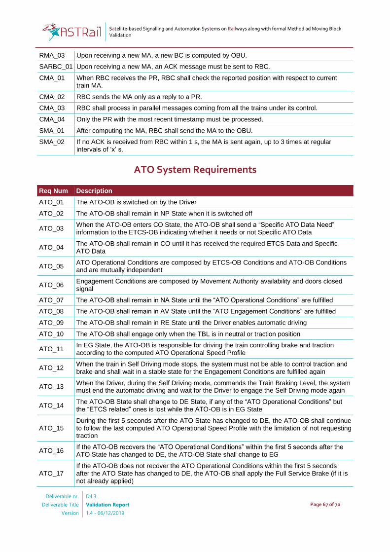
Satellite-based Signalling and Automation Systems on Railways along with formal Method ad Moving Block Validation
Deliverable nr.
Deliverable Title
Version
D4.3
Validation Report
1.4 - 06/12/2019
Page 67 of 70
RMA_03 Upon receiving a new MA, a new BC is computed by OBU.
SARBC_01 Upon receiving a new MA, an ACK message must be sent to RBC.
CMA_01 When RBC receives the PR, RBC shall check the reported position with respect to current train MA.
CMA_02 RBC sends the MA only as a reply to a PR.
CMA_03 RBC shall process in parallel messages coming from all the trains under its control.
CMA_04 Only the PR with the most recent timestamp must be processed.
SMA_01 After computing the MA, RBC shall send the MA to the OBU.
SMA_02 If no ACK is received from RBC within 1 s, the MA is sent again, up to 3 times at regular intervals of ‘x’ s.
ATO System Requirements
Req Num Description
ATO_01 The ATO-OB is switched on by the Driver
ATO_02 The ATO-OB shall remain in NP State when it is switched off
ATO_03 When the ATO-OB enters CO State, the ATO-OB shall send a “Specific ATO Data Need” information to the ETCS-OB indicating whether it needs or not Specific ATO Data
ATO_04 The ATO-OB shall remain in CO until it has received the required ETCS Data and Specific ATO Data
ATO_05 ATO Operational Conditions are composed by ETCS-OB Conditions and ATO-OB Conditions and are mutually independent
ATO_06 Engagement Conditions are composed by Movement Authority availability and doors closed signal
ATO_07 The ATO-OB shall remain in NA State until the “ATO Operational Conditions” are fulfilled
ATO_08 The ATO-OB shall remain in AV State until the “ATO Engagement Conditions” are fulfilled
ATO_09 The ATO-OB shall remain in RE State until the Driver enables automatic driving
ATO_10 The ATO-OB shall engage only when the TBL is in neutral or traction position
ATO_11 In EG State, the ATO-OB is responsible for driving the train controlling brake and traction according to the computed ATO Operational Speed Profile
ATO_12 When the train in Self Driving mode stops, the system must not be able to control traction and brake and shall wait in a stable state for the Engagement Conditions are fulfilled again
ATO_13 When the Driver, during the Self Driving mode, commands the Train Braking Level, the system must end the automatic driving and wait for the Driver to engage the Self Driving mode again
ATO_14 The ATO-OB State shall change to DE State, if any of the “ATO Operational Conditions” but the “ETCS related” ones is lost while the ATO-OB is in EG State
ATO_15 During the first 5 seconds after the ATO State has changed to DE, the ATO-OB shall continue to follow the last computed ATO Operational Speed Profile with the limitation of not requesting traction
ATO_16 If the ATO-OB recovers the “ATO Operational Conditions” within the first 5 seconds after the ATO State has changed to DE, the ATO-OB State shall change to EG
ATO_17 If the ATO-OB does not recover the ATO Operational Conditions within the first 5 seconds after the ATO State has changed to DE, the ATO-OB shall apply the Full Service Brake (if it is not already applied)

Satellite-based Signalling and Automation Systems on Railways along with formal Method ad Moving Block Validation
Deliverable nr.
Deliverable Title
Version
D4.3
Validation Report
1.4 - 06/12/2019
Page 68 of 70
ATO_18 The ATO-OB shall enter the ATO Failure State in case of a fault that does not allow performing ATO functions
ATO_19 From the Fault State, the system can only move to the not powered state
ATO_20 The authorisation for the safe release of the doors is performed by an external safe system
ATO_21 An external safe system shall ensure that the train cannot move when the doors are open
ATO-MB Integrated System Requirements
Req Num Description
ATOMB_01 OBU is required to send to ATO Train Position, MA, with no additional delay after a value change
ATOMB_02 OBU is required to send to ATO ETCS_Conditions and ATO Conditions at every execution cycle
ATOMB_03 The driver must be able to power on/off the ATO-OB
ATOMB_04 The driver must be able to set the auto-driving mode
ATOMB_05 The driver must be able to use the TBL
ATOMB_06 OBU must forward to ATO-OB the MA as it is received from the RBC and with no further modification
ATOMB_07 In case of Emergency Brake required by OBU, ETCS_Conditions are set to FALSE
ATOMB_08 In case of OBU Fatal Error, ETCS_Conditions are set to FALSE
ATOMB_09 In case of MA timeout, ETCS_Conditions are set to FALSE
ATOMB_10 ETCS_Conditions and ATO Conditions are mutually independent
ATOMB_11 The Train must forward to the ATO-OB the Doors status information (opened/closed), the train stopped condition the speed and the distance travelled
ATO State Diagram

Satellite-based Signalling and Automation Systems on Railways along with formal Method ad Moving Block Validation
Deliverable nr.
Deliverable Title
Version
D4.3
Validation Report
1.4 - 06/12/2019
Page 69 of 70
Figure A1 ATO State Diagram

Satellite-based Signalling and Automation Systems on Railways along with formal Method ad Moving Block Validation
Deliverable nr.
Deliverable Title
Version
D4.3
Validation Report
1.4 - 06/12/2019
Page 70 of 70
References
[1] UNISIG: FIS for the RBC/RBC handover, version 3.1.0 (15 06 2016) [2] The Mathworks: Simulink: Simulation and Model-based Design,
https://www.mathworks.com/help/simulink/ (Accessed 26/06/2019). [3] David, A., Larsen, K.G., Legay, A., Mikucionis, M., Poulsen, D.B.: Uppaal SMC tutorial. Int. J. Softw. Tools
Technol. Transf. 17(4), 397–415 (2015) [4] Behrmann, G., et al.: UPPAAL 4.0. In: QEST. pp. 125–126. IEEE (2006) [5] Agha, G., Palmskog, K.: A Survey of Statistical Model Checking. ACM Trans. Model. Comput. Simul. 28(1),
6:1–6:39 (2018) [6] Larsen, K.G., Legay, A.: Statistical Model Checking — Past, Present, and Future In: ISoLA. LNCS, vol.
8802, pp. 135–142. Springer (2014) [7] Arnold, A., et al.: An Application of SMC to continuous validation of heterogeneous systems. EAI Endorsed
Trans. Indust. Netw. & Intellig. Syst. 4(10) (2017) [8] ter Beek, M.H., Legay, A., Lluch Lafuente, A., Vandin, A.: Statistical Model Checking for Product Lines. In:
ISoLA. LNCS, vol. 9952, pp. 114–133. Springer (2016) [9] Cappart, Q., et al.: Verification of Interlocking Systems Using Statistical Model Checking. In: HASE. pp.
61–68. IEEE (2017) [10] Filipovikj, P., et al.: Simulink to UPPAAL Statistical Model Checker: Analyzing Automotive Industrial
Systems. In: FM. LNCS, vol. 9995, pp. 748–756. Springer (2016) [11] Gilmore, S., Tribastone, M., Vandin, A.: An Analysis Pathway for the Quantitative Evaluation of Public
Transport Systems. In: IFM. LNCS, vol. 8739, pp. 71–86. Springer (2014) [12] Puch, S., Fränzle, M., Gerwinn, S.: Quantitative Risk Assessment of Safety-Critical Systems via Guided
Simulation for Rare Events. In: ISoLA. LNCS, vol. 11245, pp. 305–321. Springer (2018) [13] Basile, D., ter Beek, M.H., Ciancia, V.: Statistical Model Checking of a Moving Block Railway Signalling
Scenario with Uppaal SMC. In: ISoLA. LNCS, vol. 11245, pp. 372–391. Springer (2018) [14] Basile, D., Di Giandomenico, F., Gnesi, S.: Statistical Model Checking of an Energy Saving Cyber-Physical
System in the Railway Domain. In: SAC. pp. 1356–1363. ACM (2017) [15] Douglass, B.P.: Real-Time UML. In: FTRTFT. LNCS, vol. 2469, pp. 53–70. Springer (2002) [16] Selic, B.: The Real-Time UML Standard: Definition and Application. In: DATE. pp. 770–772 (2002) [17] Mazzanti, F., Ferrari, A., Spagnolo, G.O.: Towards formal methods diversity in railways: an experience
report with seven frameworks. Int. J. Softw. Tools Technol. Transf. 20(3) (2018) [18] David, A., et al.: On Time with Minimal Expected Cost! In: ATVA. LNCS, vol. 8837, pp. 129–145. Springer
(2014) [19] Gadyatskaya, O., et al.: Modelling Attack-defense Trees Using Timed Automata. In: FORMATS. LNCS,
vol. 9884, pp. 35–50. Springer (2016) [20] Basile, D., ter Beek, M. H., Fantechi, A., Gnesi, S., Mazzanti, F., Piattino, A., ... & Ferrari, A. (2018,
September). On the industrial uptake of formal methods in the railway domain. In International Conference on Integrated Formal Methods (pp. 20-29). Springer, Cham.
[21] Ferrari, A., ter Beek, M. H., Mazzanti, F., Basile, D., Fantechi, A., Gnesi, S., ... & Trentini, D. (2019, June). Survey on Formal Methods and Tools in Railways: The ASTRail Approach. In International Conference on Reliability, Safety, and Security of Railway Systems (pp. 226-241). Springer, Cham.
[22] Clarke, E. M., & Wing, J. M. (1996). Formal methods: State of the art and future directions. ACM Computing Surveys (CSUR), 28(4), 626-643.
[23] Boca, P., Bowen, J. P., & Siddiqi, J. (Eds.). (2009). Formal methods: State of the art and new directions. Springer Science & Business Media.
[24] Basile, D., ter Beek, M. H., Fantechi, A., Gnesi, S., Mazzanti, F., Piattino, A., Trentini, D. & Ferrari, A. (2018). On the industrial uptake of formal methods in the railway domain. In International Conference on Integrated Formal Methods (pp. 20-29). Springer, Cham.
[25] Alessio Ferrari, Franco Mazzanti, & Andrea Piattino. (2019). ASTRail Deliverable 4.3, Task 4.4 - Supplementary Material [Data set]. Zenodo. http://doi.org/10.5281/zenodo.3377823
[26] D4.1 - ATO over ETCS GoA2 Specification - https://projects.shift2rail.org/s2r_ip2_n.aspx?p=X2RAIL-1