d4.1 requirements definition for brake by wire - safe4rail.eu · iteration of brake system and...
TRANSCRIPT

D4.1
Requirements definition for Brake by Wire
Project number: 730830
Project acronym: Safe4RAIL
Project title: Safe4RAIL: SAFE architecture for Robust
distributed Application Integration in roLling stock
Start date of the project: 1st October, 2016
Duration: 24 months
Programme: H2020-S2RJU-OC-2016-01-2
Deliverable type: Report (R)
Deliverable reference number: ICT-730830 / D4.1 / FINAL | 1.0
Work package WP 4
Due date: December 2016 – M03
Actual submission date: 30th December, 2016
Responsible organisation: ELE
Editor: Marco Breviario
Dissemination level: Public
Revision: FINAL | 1.0
Abstract:
Contains the collection of information necessary for the definition of requirements (SOTA). A first iteration of brake system and electronic control and communication requirements is provided, as well as standard and technologies applied in other transport sector and suitable for use (or as reference) for railway “brake by wire” systems.
Keywords: Braking System, Brake-by-Wire, Drive-by-Wire,
Standards, Safety.
This project has received funding from the Shift2Rail Joint Undertaking under grant agreement No 730830. This Joint Undertaking receives support from the European Union’s Horizon 2020 research and innovation programme and Austria, Spain, Germany, Czech Republic, Italy, France.

D4.1 - Requirements definition for Brake by Wire
SAFE4RAIL D4.1 Page II
Editor
Marco Breviario (ELE)
Contributors (ordered according to beneficiary numbers)
Marco Breviario, Paolo Giraudo, Ugo Prosdocimi, Nicola Papini (ELE)
Adrian Szawlowski, Erik Männel (IAV)
Reviewers
Paolo Gianotti (TUV)
Stefano La Rovere (NIER)
Martin Deutschmann, Sandra Lattacher, Mario Münzer (TEC)
Disclaimer
The information in this document is provided “as is”, and no guarantee or warranty is given that the information is fit for any particular purpose. The content of this document reflects only the author`s view – the European Commission is not responsible for any use that may be made of the information it contains. The users use the information at their sole risk and liability.

D4.1 - Requirements definition for Brake by Wire
SAFE4RAIL D4.1 Page III
Executive Summary
The main objective of WP4 of SAFE4RAIL is to develop a concept for a new railway braking system based on electronic devices and communication systems with high integrity safety performances.
The aim of this document is to grant a knowledge base about present braking system both in the railway and automotive application. SOTA information will support the following tasks of the project: system requirements specification, safety requirement allocation, risk analysis and concept development.
Chapter 1 of the document provides a not exhaustive description of the conventional railway braking system starting from the basic requirements coming from the applicable regulations and standards. Main functional, performance and safety requirements are described as well as typical system architectures able to fulfill them. Presented architectures are still based on pneumatic and/or electro-pneumatic solutions suffering from various limitations that the document tries to identify and addresses proposing alternative solutions based on safe electronic hardware and software.
In chapter 2 an overview is provided on how brake-by-wire systems are presently implemented in automotive domain with the wanted result of technologies cross fertilization.
Chapter 3 provides a brief description of the safety approach to develop electronic safety-critical systems in railway and automotive domains. In chapter 4 a state of the art analysis of the normative frameworks that shall be considered in the development of electronic solution is given.
Finally, chapter 5 reports the conclusions about this first deliverable and its use in the upcoming tasks of the WP4.

D4.1 - Requirements definition for Brake by Wire
SAFE4RAIL D4.1 Page IV
Contents
Executive Summary ................................................................................................. 3
Contents .................................................................................................................... 4
List of Figures ........................................................................................................... 6
List of Tables ............................................................................................................ 7
Chapter 1 Railway braking System ..................................................................... 8
1.1 Conventional braking system analysis ............................................................. 9
1.1.1 Standard and Legislation ....................................................................................... 9
1.1.1.1 Overview of EU regulation and EN standards ................................................. 9
1.1.2 Brake system purpose ..........................................................................................10
1.1.2.1 Friction brake ................................................................................................10
1.1.2.2 Dynamic brake ..............................................................................................10
1.1.2.3 Adhesion independent brake .........................................................................11
1.1.3 Functional requirements ........................................................................................12
1.1.3.1 Basic requirements ........................................................................................12
1.1.3.2 Emergency brake ..........................................................................................13
1.1.3.3 Parking brake ................................................................................................14
1.1.3.4 Service brake ................................................................................................14
1.1.3.5 Wheel slide protection system (WSP) ............................................................15
1.1.3.6 Passenger alarm ...........................................................................................15
1.1.3.7 Brake state monitoring ..................................................................................16
1.1.3.8 Rescue ..........................................................................................................17
1.1.4 Performance requirements ....................................................................................17
1.1.4.1 Emergency braking .......................................................................................17
1.1.4.2 Service brake ................................................................................................18
1.1.4.3 Parking brake ................................................................................................18
1.1.5 Safety requirements ..............................................................................................18
1.1.6 Architectures .........................................................................................................20
1.1.6.1 Friction brake ................................................................................................22
1.1.6.1.1 UIC Indirect pneumatic brake ................................................................................. 22
1.1.6.1.1.1 Variants on UIC indirect pneumatic brake ...................................................... 27
1.1.6.1.2 Not UIC Indirect pneumatic brake .......................................................................... 30
1.1.6.1.3 Direct brake ............................................................................................................ 30
1.1.6.2 Dynamic brake ..............................................................................................39
1.1.6.3 Magnetic track brake .....................................................................................43
1.1.6.4 Parking brake ................................................................................................44
1.1.6.5 Brake test ......................................................................................................50

D4.1 - Requirements definition for Brake by Wire
SAFE4RAIL D4.1 Page V
1.2 Limits of existing brake systems .................................................................... 51
1.2.1 Service/Emergency brake .....................................................................................51
1.2.2 Parking brake ........................................................................................................52
1.3 Possible Innovative solutions to overcome the limits ..................................... 53
1.3.1 Service/emergency brake......................................................................................54
1.3.2 Parking brake ........................................................................................................64
Chapter 2 Automotive braking system ............................................................. 65
2.1 Vehicle integration ......................................................................................... 66
2.2 Overview of hydraulic braking system ............................................................ 68
2.3 Overview of brake-by-wire systems ............................................................... 71
2.4 Advantages & disadvantages of brake-by-wire .............................................. 74
2.5 Overview of other X-by-wire systems ............................................................. 74
2.6 Outlook .......................................................................................................... 74
Chapter 3 Safety ................................................................................................. 75
3.1 Overview of CENELEC Railway Standards ................................................... 76
3.2 Automotive ..................................................................................................... 81
Chapter 4 Legislations & Standards ................................................................. 85
4.1 Railway .......................................................................................................... 85
4.1.1 Mandatory documents ...........................................................................................86
4.1.2 Voluntary documents (EN standards) ....................................................................89
4.1.3 Other standards ....................................................................................................91
4.2 Automotive ..................................................................................................... 93
Chapter 5 Summary and conclusion ................................................................. 95
Chapter 6 List of Abbreviations ........................................................................ 96
Chapter 7 Bibliography ...................................................................................... 98
D4.1 - Requirements definition for Brake by Wire
SAFE4RAIL D4.1 Page VI
List of Figures
Figure 1: Automatic brake application device (basic functional diagram) ..............................20
Figure 2: UIC Indirect pneumatic brake diagram ...................................................................22
Figure 3: Main Pipe connection diagram...............................................................................27
Figure 4: EP brake diagram ..................................................................................................28
Figure 5: Interlock valve .......................................................................................................29
Figure 6: Flowchart of principal design for an emergency brake loop (EBL) .........................32
Figure 7: EP Direct Brake Diagram .......................................................................................33
Figure 8: EP Direct Brake with safety loop ............................................................................35
Figure 9: EP Direct Brake with brake pipe ............................................................................36
Figure 10: EP Direct Brake with safety loop and brake pipe .................................................37
Figure 11: EP Direct Brake with load dependent relay valve ................................................38
Figure 12: Characteristic curve for electrodynamic brake force ............................................40
Figure 13: Characteristic curve for fluid retarder braking force ..............................................40
Figure 14: Hand brake equipment acting on disc ..................................................................45
Figure 15: Parking brake – Control with mono-stable logic ...................................................48
Figure 16: Parking brake – Control with bi-stable logic .........................................................49
Figure 17: Innovative solution – Brake command transmission ............................................56
Figure 18: Innovative solution – Brake command transmission & signalling .........................58
Figure 19: Overview of system which consist of different ECU`s (subsystems/subitems) .....66
Figure 20: Schematic of Hydraulic Brake System .................................................................68
Figure 21: Principle of a car braking system .........................................................................70
Figure 22: Sensotronic Brake Control (adapted from [29]) ....................................................72
Figure 23: Principle of a Wedge Brake (adapted from [30]) ..................................................72
Figure 24: Simplified principle of recuperation in a vehicle ...................................................73
Figure 25: Main CENELEC railway application standards ....................................................76
Figure 26 ISO 26262 V-Model ([31]) .....................................................................................81
Figure 27: Generic approach of safety requirement allocation ([31]) .....................................84
Figure 28: Hierarchy of the applicable documents for railway application .............................85

D4.1 - Requirements definition for Brake by Wire
SAFE4RAIL D4.1 Page VII
List of Tables
Table 1: Braking system in the automotive industry ..............................................................71
Table 2: CENELEC and IEC standards relationship .............................................................77
Table 3: Controllability of vehicle in a specific situation by driver (in context of HARA) .........82
Table 4: Severity of potential harm due to accident with focus on driver and environment (in context of HARA) ..........................................................................................................82
Table 5: Exposure of a specific situation for defined timeframe (in context of HARA) ...........82
Table 6: ASIL Determination ([31]) .......................................................................................83
Table 7: Directives on the interoperability of the rail system .................................................87
Table 8: Mandatory rules on the interoperability of the rail system........................................87
Table 9: Mandatory standards quoted in regulation ..............................................................88
Table 10: Presumption of conformity - Harmonized standards ..............................................90
Table 11: Other standards – Reliability .................................................................................91
Table 12: Other standards – Environmental .........................................................................92
Table 13: List of Abbreviations .............................................................................................97

D4.1 - Requirements definition for Brake by Wire
SAFE4RAIL D4.1 Page 8 of 99
Chapter 1 Railway braking System
This chapter will analyse the state of art of existing braking system evidencing the main functional and safety requirements related to the WP4 objectives (command and control of the system), describing typical system architectures and components used to fulfil above requirements. Furthermore, the strength and weaknesses of the existing architectures will be identified and it will be proposed some subjects where safe electronic hardware and software could be used to fulfil in different and more convenient way the same functional and safety requirements.
European legislation about interoperability for rolling stocks (TSI) and main European standards (EN) will be the reference in this analysis, not going into national legislation/standards/regulations. This is demanded to a second stage of analysis, even if relevant for the application in each country of the innovative technical solution which can be identified.
The analysis will focus mainly the safety related functions (directly linked to safe electronic HW and SW scope of the WP4) and shortly mention the other functions with possible improvement.

D4.1 - Requirements definition for Brake by Wire
SAFE4RAIL D4.1 Page 9 of 99
1.1 Conventional braking system analysis
1.1.1 Standard and Legislation
1.1.1.1 Overview of EU regulation and EN standards
The commission regulation (EU) no 1302/2014, so called TSI LOC&PAS (see [1]) is the actual applicable legislation in Europe for rolling stocks, describing the essential requirements applicable to rolling stock. At paragraph §4.2.4 of [1] the requirements for brake system are reported.
TSI LOC&PAS mentions at paragraph §6.2.3.5 the commission regulation (EU) no 352/2009 “Common safety method on Risk Assessment and its amendments” which is actually replaced by 402/2013 “Common safety method for risk evaluation and assessment” (see [2]). This regulation is the reference to assess the risk.
TSI define mandatory also certain requirements of following European Norms, which, due to that, take the value of law:
[13] (EN15595) §4.5.6 and §4.2.4.3 (see §4.2.4.6.2 and annex J index 30 of [1]): practically this norm about WSP is totally mandatory. WSP is a safety related function;
[7] (EN14198) §5.4: define mandatory the application of traditional UIC braking system, as described at paragraph §5.4 of the above norm, for rolling stock to be operated in general operation (train formation which is not defined at design stage, i.e. different from EMU/DMU);
[16]: EN45545-2;
[17] (EN50553), running capability, in accordance to the requirements of §4.2.10.4.4 of [1].
In general new rolling stock are designed in accordance to the requirements of norms from [5] to [8], depending from the type of train (EMU/DMU trains, High speed EMU trains, Trains hauled by locomotive). These norms represent the recent summary of the experience accumulated since the beginning of the railway industry about braking systems. These standards collect in single norms all functional requirements of the braking system that in former UIC norms were spread in several leaflet not always harmonized. UIC leaflet had also the limit to consider only one type of mechanical braking system (indirect pneumatic brake), which is no more considered as the only one applicable by the EN norms, even if it is still considered the reference one for its safety characteristics. Above standards ask for risk analysis to be done according EN 50126 ([3]).
Mass transit (tramways light rail vehicles, metros, commuter trains) is generally under the local legislation and safety authorities and is regulated by the standard in [9] (EN 13452-1). This standard requires risk analysis in accordance to EN 50126
The passenger alarm is subjected to TSI ([1]) §4.2.5.3 and is a safety related function. EN standard 16334 ([14]), based on same requirements of TSI, integrates them with more details ones. This standard requires risk analysis in accordance to EN 50126
Standards from [18] to [24] refer to typical pneumatic components of the conventional pneumatic brake system. They can be a reference of the current requirements about brake force application, time response (distributor and relay valve) or for diagnostic signals relevant for safety.

D4.1 - Requirements definition for Brake by Wire
SAFE4RAIL D4.1 Page 10 of 99
1.1.2 Brake system purpose
As mentioned in TSI §4.2.4.1 the purpose of a braking system is “to ensure that the train's speed can be reduced or maintained on a slope, or that the train can be stopped within the maximum allowable braking distance. Braking also ensures the immobilisation of a train”.
It means that the two main functions are:
reduce the speed, maintain the speed on slope, stopping the train by applying a retarding force during running;
immobilize the train in standstill for an unlimited period of time.
Additional functions are then to be considered, but all of them oriented to the above two ones.
Retarding force can be generated in different ways:
friction brake;
dynamic brake;
independent of adhesion condition brake;
and all of them can be used at the same time, under limitation in terms of adhesion between wheel and rail, and of jerk.
Immobilizing force is only by friction brake or independent of adhesion brake (in case of use permanent magnets, see [5] §5.2.4).
The friction force generated to stop the train can be used for temporary train immobilization (min 2 hours).
1.1.2.1 Friction brake
Typical friction brake types are ([5] §5.2.3, [6] §5.2.3):
disc brakes, designed as wheel mounted, axle mounted or transmission mounted discs
tread brakes, operating on the wheels
Other type of friction brakes can be used, if appropriate.
1.1.2.2 Dynamic brake
Typical dynamic brake types are ([5] §5.3, [6] §5.3)
electro-dynamic brake, operating the traction motors in the generator mode
This type of brake can return the energy to the catenary or dissipate it on rheostat. In the first case it is dependent from catenary voltage (regenerative braking), in the second not (rheostatic braking).
It is necessary that all of the auxiliary devices used for the conversion of the energy
are fully functional without being dependent on electrical energy from the main power
supply;
hydro-dynamic brake: the brake force is produced by viscous shear in a hydraulic
transmission

D4.1 - Requirements definition for Brake by Wire
SAFE4RAIL D4.1 Page 11 of 99
They are adhesion dependent brakes that can operate at the same time of friction brake taking into account the maximum allowed wheel–rail adhesion limits.
In case of electro-dynamic brake unit failure, the missing force can be replaced by other type of braking systems on the train (e.g. friction) or by other electro-dynamic brake units, based on still available margin on used adhesion and power.
Being wearless the dynamic brake has the highest priority in service braking.
Another type of dynamic brake is the
eddy-current brake: the brake force is produced by Eddy current (Foucault)
generation in the rail by electromagnetic field.
It has the advantage to be an adhesion independent braking force, so similar to the magnetic track brake, but without contact with the rail, so wear-less. It generates a quite high and constant force over the whole speed range.
The above two characteristics make it interesting as alternative to magnetic track brake (see §1.1.2.3) for high speed train.
The use of this type of brake has restriction linked to the force and heat generated on the rail.
Refer also to [6] §5.5
1.1.2.3 Adhesion independent brake
Typical adhesion independent brake type is the Magnetic Track Brake (see [5] §5.2.4). The brake force is produced by friction between the rail surface and shoes, forced magnetically into contact with it.
There are the following types of magnetic track brake.
Electromagnetically excited, battery supported track brakes, in an upper position and
clearance free in the bogie frame in the release status (lowering actuator needed).
Permanently magnetically excited track brakes, in an upper position and clearance
free in the bogie frame in the release status (lowering actuator needed).
Electromagnetically excited, battery supported track brakes, in lower position in the
release status (no lowering actuator needed, it is sufficient the excitation of the
magnet to put in contact the magnet with the rail).
Magnetic track brake is used only in emergency brake or by driver, voluntary independent command.
Considering that not all countries allow the use of MTB, it shall be possible the inhibition of the command in emergency.

D4.1 - Requirements definition for Brake by Wire
SAFE4RAIL D4.1 Page 12 of 99
1.1.3 Functional requirements
In the following paragraphs the main functions requested to brake system by TSI, EN standards and normal practice are described. The following chapter doesn’t provide a complete definition of the relationship between the different functions of the braking system. Some interactions are specified in §1.1.6 where the main architectures able to fulfil the following requirements are described, but the specification of the hierarchical relations between the functions will be subjected of a dedicated analysis not addressed by this document.
1.1.3.1 Basic requirements
The brake system shall consist of, at least, the following type of brakes.
Emergency braking: application of a predefined brake force in a predefined maximum response time in order to stop the train with a defined level of brake performance.
Service braking: application of an adjustable brake force in order to control the speed of the train, including stop and temporary immobilisation.
Parking braking: application of a brake force to maintain the train (or the vehicle) in permanent immobilisation in a stationary position, without any available energy on board.
Being the interruption of the train service to be reduced as much as possible, reliability of the brake system is important and for this reason generally back up service brake command is normally requested.
The basic requirements are represented by the following characteristics (typical of the traditional UIC indirect pneumatic brake, as described in §1.1.6.1).
1) Continuity: the brake application signal is transmitted from a central command to the whole train by a control line.
2) Automaticity: an inadvertent disruption (loss of integrity, line de-energised, etc…) of the control line leads to brake activation on all vehicles of the train. In case of unintentional train separation during running, the two parts of the train shall be brought to a standstill.
3) Inexhaustibility: there shall be sufficient braking energy available on board (stored energy), distributed on each vehicle, to ensure the application of the required brake forces. This requirement can be also translated in following way: it shall be possible to release the brake only if it is possible to brake again.
4) Energy to release command signal.
5) Decentralized brake actuators, developing the brake force.
6) Proven design components (see Annex B of [5] for the definition).
The above basic requirements are applicable:
to emergency brake function when train is in running condition, in order to guarantee the stopping of the train;
to immobilization and parking brakes when train is standstill;
and are generally considered the minimum requirements which guarantee a safe braking system (see [5] §5.1.1 and [6] §5.1.1).
For immobilization the inexhaustibility shall be guaranteed on maximum slope and maximum load at least for two hours by brake system. For longer time and tare load the parking brake

D4.1 - Requirements definition for Brake by Wire
SAFE4RAIL D4.1 Page 13 of 99
system shall guarantee a minimum braking force (depending from the customer requirement) for an unlimited period of time.
A further basic requirement is related to the behaviour in case of fire on board.
7) Running capability: the brake system shall be designed in a way to don’t generate an undue application of the brake in case of presence of fire on the train.
This requirement can be satisfied by means of proper design of the brake system, but also by means of prevention and extinguishing of the fire. For these aspects the relevant norms are [15], [16] and [17].
1.1.3.2 Emergency brake
The emergency brake can be initiated by:
braking devices on the driving cab desk,
signalling system,
TCMS (Train Control and Management System),
local emergency command device located along the train,
passenger alarm system.
For not UIC brake system, emergency brake has also to be automatically triggered (by proper device among above) when the main pipe is too low, in order to guarantee the inexhaustibility function of the system.
The emergency brake, in addition to the basic requirements listed in §1.1.3.1, has following requirements about emergency command which guarantee the high integrity level of this type of brake:
redundant devices to initiate the emergency brake and also redundant components on emergency brake electrical command chain;
priority on any other brake and release command;
safe traction cut off at emergency triggering;
Dynamic brake (see §1.1.2.2) can be used in emergency, with the condition that it is commanded by the main brake system control line and that a safety analysis is done about the hazard “complete loss of dynamic brake force” (see [1] §4.2.4.7).The monitoring of the dynamic brake or braking system linked to traction system is mandatory during running in case the dynamic brake contribute to the emergency brake performance (see [1] §4.2.4.9).
If adhesion independent brakes (see §1.1.2.3) are present, application is commanded by the main brake system emergency brake control line. A safety analysis must be done about the hazard “complete loss of adhesion independent brake force” (see [1] §4.2.4.7).The test of this type of brake shall be part of the tests to be performed at the beginning of the service at standstill to assess the brake system functionality of the train (see [1] §4.2.4.9). Furthermore the correct application during emergency brake shall be permanently monitored (see [6] §5.6). For further functional requirements see [22].
Adhesion dependent brakes (electro/hydro dynamic brake and friction brake) can be load dependent (especially on train with big variation between tare and crush load) in order to avoid too high adhesion levels in tare condition (mass transit, regional trains, …). This can be obtained by mechanical devices operating on local friction brake application components or electronically by sensor detecting the weight of the train and regulating the force level according it. In case the load dependency is used in emergency brake a safety analysis shall

D4.1 - Requirements definition for Brake by Wire
SAFE4RAIL D4.1 Page 14 of 99
be done about single failure on load regulation system (see §1.1.5 cl. 2). In case of failure of the weighting system, it has to be defined the criteria to be used, if default to crush or to tare.
Emergency brake can be managed by speed dependent braking forces. This to comply with adhesion requirements and with thermal dimensioning of the discs/wheels. In case the speed dependency is used in emergency brake a safety analysis shall be done about single failure on speed management system (see §1.1.5 cl. 2)
In general emergency brake shall be submitted to risk analysis taking in consideration every single failure scenario affecting brake performances(see §1.1.5).
1.1.3.3 Parking brake
The parking brake can be applied by voluntary action by the driver (electrical device installed on the desk) or by automatic application when the energy in charge of the immobilization is lowering.
The parking brake shall be automatically applied at train switch off (or by automatic command from TCMS, electrical devices or by automatic application as above).
The parking brake monitoring shall be guaranteed for the following main functions:
detect any undue application during running;
recognize the efficiency of parking brake at standstill;
diagnose correct isolation and manual release of any parking brake unit and take it in consideration in the efficiency evaluation (based on the expected performances).
Parking brake is of course safety relevant and has to be assessed to related hazard case described in §4.2.4.2.2 of TSI (see §1.1.5)
Note: in certain particular case parking brake is also allowed to be a back-up brake in case the emergency brake is not applied to the whole train.
1.1.3.4 Service brake
Service brake is the type of brake used for normal speed regulation and stopping of the train. The service brake force is adjustable, continuously or by step (minimum 7).
Service brake can be controlled by:
brake lever on the desk (which can be integrated with the traction lever in the master controller);
TCMS for automatic regulation of the speed;
signalling, for speed reduction in case of warning curve overridden.
Dynamic brake has priority because wear-less.
Service brake is normally load dependent where a weighting system is present on the train.
Dynamic brake must be integrated by friction brake when it is not able to give the necessary retarding force or in case of failure of any single traction unit/motor. At low speed the dynamic brake is completely replaced by friction brake to stop the train. The management of the friction and dynamic brake force is called “blending management”.
Blending management can be done at car level, unit level or train level. The management shall guarantee not only the priority of use of dynamic brake, but also correct management of the used adhesion (based also on weighting) and of the mechanical energy transmitted to the discs or wheels.
D4.1 - Requirements definition for Brake by Wire
SAFE4RAIL D4.1 Page 15 of 99
Service brake needs normally a back-up brake command, so that in case of failure of the main command the driver has the possibility to move the train, even if in degraded condition (for example no dynamic brake, or not adjustable brake).
1.1.3.5 Wheel slide protection system (WSP)
WSP makes the best use of available adhesion by a controlled reduction and restoration of the brake force to prevent wheelsets from locking and uncontrolled sliding, thereby minimising the extension of stopping distances and possible wheels damage.
WSP system applies to both dynamic and friction brake.
WSP function is mandatory for trains maximum speed above 150 km/h or with used wheel-rail adhesion higher than 0,11 (0,12 in case of tread brake).
WSP system monitors the rotation of the axles and releases the brake if wheel slide is detected. Due to its action on releasing of the brake, the WSP is relevant for safety. For this reason a so called “watchdog function” shall be implemented by independent electronic components to cancel release command to the valves lasting more than a certain time. According to §4.2.4.6.2 of TSI, the WSP components failure shall be considered in the risk analysis regarding emergency brake in §4.2.4.2.2.
As written above the application of WSP system compliant to the EN 15595 ([13]) is a mandatory requirement by TSI.
The status of the WSP system shall be permanently monitored and reported in the cab or visible to train staff. A visual indication of the intervention of WSP is often requested to allow the driver to adapt, if possible, the service brake demand to the available adhesion.
WSP test has to be performed periodically on all the train, checking the functionality of the valves and of the electronics.
1.1.3.6 Passenger alarm
The passenger alarm function gives to anyone in the train the opportunity to advise the driver of a potential danger, and has consequences at operating level when activated (braking initiation in absence of reaction from the driver).
The mains function are the following.
When the train is stopped at a platform or departing from a platform, activation of a passenger alarm shall lead to a direct application of the service brake or the emergency brake, resulting in a complete stop. In this case, only after the train has come to a complete stop, a system shall allow the driver to cancel any automatic braking action initiated by the passenger alarm.
In other situations, 10 +/-1 seconds after activation of the (first) passenger alarm, at least an automatic service brake shall be initiated unless the passenger alarm is acknowledged by the driver within this time. The system shall allow the driver to override at any time an automatic braking action initiated by the passenger alarm.
System in degraded condition shall apply immediately at alarm activation the emergency or service brake.
Visual and acoustical indication in the cab and where the passenger pull the handle shall be generated at alarm activation. In case of failure of the passenger alarm, a visual indication of system in degraded condition has to be activated in the cab.
On the driver's initiative, the system shall allow a communication link to be established between the driver's cab and the place where the alarm was activated.

D4.1 - Requirements definition for Brake by Wire
SAFE4RAIL D4.1 Page 16 of 99
The passenger alarm is submitted to the TSI requirements in §4.2.5.3. and it is a safety relevant function. Risk analysis according hazard described in §4.2.5.3.5 of TSI shall be done.
A train with a passenger alarm system in degraded condition does not meet the minimum requirements for safety and interoperability.
Passenger alarm system involves physical command line along the train transmitting the alarm from any vehicle to the cab. When a train is put in service it shall be possible to check the continuity of the command line and the correct operation of the system.
1.1.3.7 Brake state monitoring
The diagnostic of brake system has a safety relevance because the status of the system can have impact on train performances.
Brake Tests:
when at standstill, at least, it shall be possible to check:
the continuity of the train brake control command line;
the availability of the braking energy supply along the train;
the status of the main brake (brake systems participating to emergency brake) and parking brake systems and the status of each part (including one or several actuators) of these systems that can be controlled and/or isolated separately, excepted for dynamic brake and braking system linked to traction systems.
Permanent diagnostic:
when running, the following permanent monitoring requirements shall be guaranteed:
the status of the train brake control command line;
the status of the train brake energy supply;
the status of the dynamic brake and braking system linked to traction system where they are included in the performance of the emergency braking in normal mode;
the status applied or released of at least one part (actuators) of the main brake system which is controlled independently (e.g. the part which is installed on the vehicle fitted with an active cab). This involve friction and adhesion independent brake
According TSI, where a centralised control system allowing the train staff to perform above checks from one location is provided, it shall be subjected to a reliability study, considering the failure mode of components, redundancies, periodic checks and other provisions; the brake test requirements are well detailed in EN 16185-1 ([5]) and EN 15734-1 ([6]).
Other safety related requirements about status and fault monitoring are already mentioned in the above chapters related to control of the energy availability, parking brake, WSP and Passenger alarm status and tests. Additionally, for not UIC systems and for trains with MTB (Magnetic Track Brakes) using air to pull down the magnets, the monitoring of main reservoir pressure (and/or of the brake reservoir) becomes an information necessary to guarantee the inexhaustibility requirement.
In addition to the above safety relevant information, brake system is subjected to state of the art about diagnostic. In principle every Last Replaceable Unit (LRU) should be monitored directly or indirectly by proper sensors to identify failure status or actual status; physical value of the relevant physical quantities; etc…
D4.1 - Requirements definition for Brake by Wire
SAFE4RAIL D4.1 Page 17 of 99
Condition based maintenance approach is now also orienting in general the design of diagnostic. It has be the objective to anticipate the failure of the components by monitoring their behaviour, allowing to have no more periodical maintenance, but “condition based”.
This approach is of course less applied on safety related systems like brakes, but it could be in the future at least for certain components.
1.1.3.8 Rescue
The rescue of a faulty train by a locomotive with UIC brake shall be always possible. To reach this goal with rescued train without UIC brake, it can be possible to have a part of the brake system of the rescued train controlled by means of an interface device; in order to meet this requirement, it is allowed to rely on low voltage provided by a battery to supply control circuits on the rescued train.
1.1.4 Performance requirements
UIC544-1 norm ([12]) defines braking performances based on total stopping distances from different initial speed. Tests are performed on single vehicles or on trains and the result (stopping distances) are used to define the braked mass of the vehicle or train.
The braked mass represent the level of braking force.
The braked mass of the whole train is the sum of the braked mass of each vehicle in service (not isolated).
The stopping distance from a certain speed is reverse proportional to the braked mass percentage, which is obtained by the ratio of the braked mass and the mass.
Actually the brake performances are defined as well by:
deceleration rate in different speed range;
equivalent response time (as defined in standard EN14531).
Above values are defined by tests.
The stopping distance from any speed is a consequence of above values by formulas.
1.1.4.1 Emergency braking
The emergency braking performance is defined by taking in to account different operative modes.
Normal mode: no failure in the brake system and nominal value of the friction coefficients (corresponding to dry conditions) used by friction brake equipment.
Degraded mode: it shall consider possible single failures and nominal value of the friction coefficients used by friction brake equipment; to that end, the emergency braking performance shall be determined for the case of single point(s) failure(s) leading to the longest stopping distance,
Degraded conditions: reduced values of pad friction coefficient and wheel to rail are considered
The combination of above cases, for all possible loads (tare, normal, crush), gives the worst performance possible, which shall be attribute to the train as guaranteed braking parameters (deceleration rate and equivalent time).

D4.1 - Requirements definition for Brake by Wire
SAFE4RAIL D4.1 Page 18 of 99
These braking parameters are used for example by ERTMS or SCMT to build the braking curve of the train, define in real time the guaranteed stopping distance, and based on that eventually to limit the speed of the train.
If there is not an advanced signalling system the braked mass is used as entry data inside predefined tables, which give as output the maximum speed.
The equivalent response time for EMU/DMU shall be lower than:
3 seconds for units of maximum design speed higher or equal to 250 km/h;
5 seconds for other units
Maximum delay time: 2 s
The maximum train deceleration rate is 2,5 m/s2
The target performance of a train is defined by the customer. For the high speed train (≥ 250 km/h) a maximum value is defined by TSI.
The maximum jerk is 4 m/s3.
1.1.4.2 Service brake
Service brake shall not provide better performances than emergency brake (see [1] §4.2.4.5.3).
1.1.4.3 Parking brake
Immobilization shall be possible in tare load on a gradient of 4%.
Parking brake shall guarantee immobilization minimum on a gradient of 5% in tare load. If the parking brake is not dimensioned for the maximum gradient of 4%, on board shall be present additional means (e.g. scotches).
Parking brake performance shall be guaranteed with single brake unit not working (see [5] §5.11.4).
1.1.5 Safety requirements
The functional and performance requirements include already safety related requirements.
This chapter intends to focus on hazard cases which shall be considered in the risk analysis of the brake system. The emergency brake requires the highest safety integrity level since, as reported in 1.1.3.2, emergency has priority on any other brake and release command, and service brake shall not provide better performances of emergency brake (see 1.1.4.1).
The following hazard cases are defined by TSI ([1], §4.2.4.2.2)
1) After activation of emergency no deceleration of the train due to:
a) Brake system failure
OR
b) Traction system failure (traction force > braking force)
This hazard doesn’t accept single failure.
TSI asks as well at §4.2.4.6.2 that the relevant components of the wheel slide protection system shall be considered in the analysis of brake system failure.

D4.1 - Requirements definition for Brake by Wire
SAFE4RAIL D4.1 Page 19 of 99
2) After activation of emergency stopping distances longer than nominal one due to failure in braking system.
This hazard requires the identification of each single failure which can lead to longer stopping distance and the effect on stopping distance to be considered in the train minimum guaranteed performance definition.
In case of use of more than one type of braking during emergency brake (friction brake, dynamic brake, independent of adhesion condition brake) the failure analysis shall be applied to all the types of brake.
TSI asks as well at §4.2.4.6.2 that the relevant components of the wheel slide protection system shall be considered.
In case of speed/load dependent braking force, devices in charge of the management of the speed/load dependent command operating on force control system shall be part of the safety analysis.
3) After activation of a parking brake complete and permanent loss of parking brake force.
This hazard doesn’t accept single failure.
Passenger alarm system has to be subjected to risk assessment as well, as indicated in TSI §4.2.5.3.5:
4) “failure in the passenger alarm system leading to the impossibility for a passenger to initiate the activation of brake in order to stop the train when train departs from a platform”;
5) ”failure in the passenger alarm system leading to no information given to the driver in case of activation of a passenger alarm”.
Diagnostic system in charge of brake test shall be subjected only to reliability study, as required in §4.2.4.9 of TSI.
Following additionally hazards are considered by EN 16185 ([5]) and EN 15734-1 ([6]) §5.1.1:
6) the brake force applied is greater than the maximum design level;
7) automatic emergency brake not initiated in case of train separation;
8) required parking brake performance not achieved;
9) loss of parking brake force over the time;
10) holding brake for brake test not achieved (only EN15734-1);
11) undue local application of brake force;
12) locked axle not detected;
13) traction activation during braking (< braking force);
14) any brake component failure leading to death or injury or damage to the train or infrastructure (mainly related to mechanical components).
EN 13452-1 ([9]) §5.6.1 mentions as safety criteria to be assessed (according [3]) the compliance with minimum performances requested by Safety Authority also in case of single failure.

D4.1 - Requirements definition for Brake by Wire
SAFE4RAIL D4.1 Page 20 of 99
1.1.6 Architectures
In this chapter the brake architectures most used to realize the brake functions are described.
A brake architecture, of course, combines more than one type of brake, but in principle, for each of them, it should consist of:
energy supply necessary to generate the braking force;
local energy store;
brake command generation;
brake command transmission;
brake force generation (transformation of brake command into brake force, using the
local energy store).
This can be resumed by the scheme shown at §5.2 of [7] and reported in Figure 1.
Figure 1: Automatic brake application device (basic functional diagram)

D4.1 - Requirements definition for Brake by Wire
SAFE4RAIL D4.1 Page 21 of 99
The splitting of functions between train level and vehicle level, separates the functions with high safety impact (object of the hazards in §1.1.5 cl. 1) able to influence the braking application of the whole train, from the functions where a single failure can be tolerated if mitigated (failures object of the risk analysis mentioned in §1.1.5 cl. 2).
The train service brake command can be intended in two way:
train retarding force request, generating a retardation proportional to the command.
The force is obtained by the use of the different type of brakes available on the train.
The way to split the force among them depend from the architecture and logics used
on the single train.
single brake type braking command: it can be possible to generate independent
request of braking force to each type of brake (friction, dynamic, adhesion
independent)
The brake command transformation into brake force can be done only at local level, determining an intrinsic redundancy of the brake system. The failure of a single conversion unit have a more limited effect on brake performance.
Any brake architecture shall comply with the basic requirements mentioned at §1.1.3.1.
Continuity.
Automaticity.
Inexhaustibility.
Energise to release brake command line.
Decentralized brake actuators, developing the brake force using locally stored energy.
Proven design components.
The requirement “decentralized brake actuators” is fulfilled by the architecture if every vehicle
has its local energy storage and its local generation of brake force.
The requirement "proven design component" is fulfilled by the architecture if the
recommendations in Annex B of [5] are put in practice.

D4.1 - Requirements definition for Brake by Wire
SAFE4RAIL D4.1 Page 22 of 99
1.1.6.1 Friction brake
1.1.6.1.1 UIC Indirect pneumatic brake
This type of brake is the most common used brake architecture in Europe.
Figure 2: UIC Indirect pneumatic brake diagram
It is composed, as a minimum, of:
1. Energy supply (1)
The air compressor, normally installed on the same vehicle where there is the driver’s brake valve, supply pressurized air to the driver’s brake valve reservoir (2), storing the air used to command and supply the brake system. There is of course a check valve preventing back flow of air between compressor and reservoir.
The size of the reservoir is generally dimensioned to guarantee a full release of the brake in case of unavailability of the supply (1).
The medium voltage electric energy supplying the compressor is provided, via auxiliary converter, by catenary in case of EMU train or by diesel engine in case of DMU.
1
8
7
6
5 4
3
2
9
10
11 11
8
7 9
10

D4.1 - Requirements definition for Brake by Wire
SAFE4RAIL D4.1 Page 23 of 99
2. Brake command generation
a) Service brake
The command is generated by pneumatic driver’s brake valve according to [5] (3), supplied by air from the above reservoir and regulating, by a position dependent or time dependant logic, the pressure at the output port connect with the brake pipe:
5 bar: brake released
4,6-0,1 bar: first step of service brake application (necessary to send a pressure wave along the train to isolate the communication between distributor and auxiliary reservoir, see below)
4,6-0,1÷3,4-0,2 bar: service brake regulation range
≤3,4-0,2 bar: maximum braking effort (emergency)
This device can be fully pneumatic or also electronically controlled (electronic driver’s brake valves). If electronic is used a fully pneumatic back-up device is generally provided, integrated or separated by the main driver’s brake valve.
When indirect brake architecture is used the pneumatic driver’s brake valve is used to control the overall train retarding force (dynamic + friction brake). There are electrical contacts or position transducer or pressure sensor on brake pipe used to define the dynamic brake request and, in case of electronic driver’s brake valve, also to manage the blending between the two type of brake. The blending is done by changing the brake pipe pressure depending from the efficiency status of the dynamic brake (at same overall request, e.g position of the driver’s brake valve)
b) Emergency brake
The command is given by:
driver’s brake valve last position, directly venting the brake pipe;
emergency devices directly venting brake pipe (4-5). This devices are manual (available for drivers or train crew), electro-pneumatic (controlled by train TCMS or by signalling/safety devices or by passenger alarm system). They can be placed everywhere along the train, being the brake pipe continuous, and in the necessary quantity.
The use of a positive pressure signal to release fulfil the requirement of “energy to release”.
The driver’s brake valve has to guarantee leakages compensation (which can cause undue brake application or reduce the braking energy stored). However, the leakage compensation shall be limited in order to guarantee the automatic application of the brake in case of disruption of the brake command line.
Standard [18] defines clearly requirements and test to be performed to assess the compliance of the driver’s brake valve. The compliance to this standard allows indirect UIC pneumatic brake command to comply the safety requirements.
3. Brake command transmission (6)
A pneumatic pipe, 25 mm minimum inner diameter called brake pipe, transmits the pressure command and the pneumatic energy supply to the whole train.

D4.1 - Requirements definition for Brake by Wire
SAFE4RAIL D4.1 Page 24 of 99
This type of command transmission and the type of signal (energy to release) fulfil the requirements of continuity and allow at local level to guarantee the automaticity.
The condition to guarantee the continuity is of course that the pipe is continuous from the front of the train till the end. For this reason before the start of the service, a brake test checking the continuity of the brake pipe has to be performed. It is normally done by applying a small brake pipe reduction (between 0,5 and 1 bar of reduction) and checking that brake are applied and released on the whole train.
In some case the continuity is checked also verifying additionally that brake pipe in driver’s cab is lowering when an emergency brake is triggered from the end of the train. This additional check, together with the previous one, assures that the venting of the air from the brake pipe is ok in both direction of the air flow (no check valve effects are produced by any undue obstructions present on the pipe).
4. Local energy store (7)
The local energy storage is the “auxiliary reservoir”, filled by brake pipe and providing energy to the local brake force generator. It means that it will be not possible to release the brake (brake pipe pressure at 5 bar) without having again refilled till a sufficient value the auxiliary reservoir.
This is a typical characteristic of UIC indirect brake, because brake energy supply and brake command are done by the same line: the brake pipe.
By this characteristic the system fulfils the requirements of inexhaustibility.
5. Brake force generation.
It is composed of the following main pneumatic devices.
a) Local distributor valves (8).
This device is designed according to [18], including a control reservoir and connected to auxiliary reservoir.
Among the several functions required (see §6.6 of [18]) the most relevant is the following.
Automatic braking: if there is a fast venting of the brake pipe the distributor applies the maximum brake pressure at the output port.
To do it the distributor uses the built in control reservoir pressure as “memory” of the release command: it is connected to the brake pipe when the pressure is close to release command, and isolated from brake pipe when there is a fast lowering of the pressure in brake pipe.
Distributor compares for the whole length of the braking the release pressure level inside the control reservoir with the braking command pressure on the brake pipe and acts adequately.
To allow the isolation of the control reservoir also during service brake the driver’s brake valve generates as first braking step a fast 0,4+0,1 bar pressure step.
The automatic braking function guarantees the automaticity of the brake application also in case of train separation or brake pipe disruption (big leakage).
b) Local Relay valve (9).

D4.1 - Requirements definition for Brake by Wire
SAFE4RAIL D4.1 Page 25 of 99
This device is designed according [21]. Its function is to amplify in terms of air delivery the output by distributor in order to have proper capacity to fill all the brake cylinder generating the brake forces on the pads.
Relay valve has often the possibility:
to apply a ratio between input pressure an output pressure;
to manage the load dependency (by additional input pressure signal from pneumatic suspension (11) which change the output force depending from the weight);
to have a double stage pressure regulation to be able to change the braking friction force at constant brake pipe command signal in case of blending or force regulation depending from the speed range.
It works by internal closed loop pneumatic control which guarantees stable level of pressure regulation.
In certain case the relay valve is not necessary because the distributor is able to supply with the sufficient air delivery the cylinders.
c) Local Brake Cylinders (10).
They are brake force actuators, transforming the pressure signal into brake force applied perpendicular to the disc or the wheel, which, by friction effect due to the relative movement between pad and disc/wheel is transformed into braking force between rail and wheels.
Conclusion:
The minimum safety requirements prescribed by [5] (see §1.1.3.1):
continuity,
automaticity,
inexhaustibility,
energise to release brake command line,
decentralized brake actuators, developing the brake force using locally stored energy,
proven design components,
are fulfilled by UIC indirect pneumatic brake. The continuity is guaranteed by the check of the correct application of the brake till the end of the train, the automaticity and inexhaustibility by the driver’s brake valve and distributor design, the energize to release brake command by the indirect concept of brake pipe.
This type of brake has the big advantage to be robust, simple, service proven since more than hundred years, using as both energy and command transmission the air, allowing very simple and reliable connection between different vehicles.
This type of brake is particular useful in variable train composition and for good transportation and rescue condition thanks to the fact that it doesn’t need electric energy supply.
It has to be remarked that EN standards from [5] to [7] always mention the UIC pneumatic indirect brake system as reference system in terms of safety:
a) EN15734-1 §5.1.1:
Mentioned characteristics of the UIC brake system making it robust in terms of safety:

D4.1 - Requirements definition for Brake by Wire
SAFE4RAIL D4.1 Page 26 of 99
a) continuous, automatic and inexhaustible brake system;
b) the medium is compressed air with its favourable properties;
c) an energized (pressurized to release) brake pipe;
d) decentralized brake actuators, developing the brake force;
e) proven design components.
b) EN16185-1 §5.1.1
“a brake system which is considered to be safe shall incorporate the following items:
n) a continuous, automatic and inexhaustible brake system
o) an energise to release brake command line, as a minimum for the emergency brake
p) decentralized brake actuators, developing the brake force using locally stored energy
q) proven design components, see annex B (Explanation of proven design concept)
An accepted bench mark safety level for a brake system is the brake architecture as described in EN14198.
If other system architectures are selected, they shall meet requirements n) to q) in an equivalent manner”.
The continuity and automaticity characteristics of brake command are well reproduced also by train wire commands with the same principle of brake pipe (energize to release), but the inexhaustivity is a property of the full pneumatic system that cannot be fully realized in the same way by electropneumatic system.
In fully pneumatic system the command to release the brake provide the energy to brake, it means that it is intrinsically inexhaustible: brake cannot be released if it is not able to brake again. With electropneumatic system the same function can only be performed by
indirect functions, not intrinsically inexhaustible.
The “favourable properties” of the compressed air as “medium” in terms of command could be identified in the following:
single medium necessary for both command and energy supply (air);
robustness of the signal transmission line (metallic pipes + flexible hoses);
self-reacting system to small disturbances on the command signal (small leakages
compensation);
high disturbances on the command signal (big leakages) generating automatic
application of the brake.
Of course there are as well some unfavourable properties, but not linked to the safety:
limited response time of brake command, in particular for long trains (limit is given by
the maximum speed of 300 m/s of the pressure wave and by the volume of air to be
exhausted);
low flexibility, in particular about blending logics and speed dependent braking force
(on-off commands);
weight/cost of components (pipes, components);
volume of components;
maintenance cost of components.

D4.1 - Requirements definition for Brake by Wire
SAFE4RAIL D4.1 Page 27 of 99
1.1.6.1.1.1 Variants on UIC indirect pneumatic brake
The above mentioned architecture can have different variants, here the most relevant are mentioned.
a) Triple valve
This is the first type of indirect automatic continuous inexhaustible brake.
The triple valve is the “father” of actual distributor. It is a valve connecting brake pipe, auxiliary reservoir and brake cylinder. It doesn’t allow to have adjustable brake force, but a single step of braking force.
When the brake pipe is close to release pressure, the valve open communication between brake pipe and auxiliary reservoir, refilling it, and vent the cylinders.
When the brake pipe pressure is suddenly lowered, it closes the communication between brake pipe and auxiliary reservoir, and opens the communication between this last and the cylinder creating a balance pressure function equals to the initial pressure multiplied by the ratio between initial volume (of the reservoir) and final volume (reservoir + pipes + cylinder).
With this type of brake there is no need of relay valves.
This type of UIC brake is normally used in combination with direct brake (pneumatic or electro-pneumatic)
b) Auxiliary reservoir supplied in parallel by main pipe
In order to speed up the refilling of the auxiliary reservoir and consequently the release of the brake, practically all the passenger trains actually have, in parallel to the brake pipe, a so called main pipe, connected to the air compressors, supplying the auxiliary reservoir in parallel to the distributor (see Figure 3). A check valve protect the auxiliary reservoir from back flow to main pipe.
Figure 3: Main Pipe connection diagram
Main pipe
Brake pipe

D4.1 - Requirements definition for Brake by Wire
SAFE4RAIL D4.1 Page 28 of 99
c) Electro-pneumatic brake
This solution allows to increase the command transmission speed: when a pneumatic braking or release command is given by the driver’s brake valve an electric signal is generated as well, venting or supplying on each single vehicle the brake pipe by solenoid valve connected to it. The release valve connects brake pipe to the main pipe (by choke), the venting pipe exhaust the brake pipe (by choke).
Figure 4: EP brake diagram
This functionality is particularly useful for long trains, where the release of the brake with traditional UIC brake can be long.
This functionality can affect the continuity and automaticity requirements of the brake.
There are two transmission lines controlling the brake pipe pressure (brake pipe
and electro-pneumatic brake electrical control lines) and local connection of brake
pipe with main pipe. The single failure of electric transmission line could affect the
brake pipe regulation.
Brake pipe is no more controlled by a single point (driver’s brake valve or
emergency push button in the cab), but from multiple points along the train: all the
solenoid valve on different vehicles.
An undue local refilling of the brake pipe can influence the automatic brake
application in case of emergency brake or brake pipe disruption.
EP Release Command Line
EP Brake Command Line

D4.1 - Requirements definition for Brake by Wire
SAFE4RAIL D4.1 Page 29 of 99
UIC leaflet [19] specifies the architecture principle for this type of brake command in order to guarantee a safe enough electric command of the valves.
From a pneumatic point of view a scheme giving priority to venting is normally used and a choke limits the air flow to brake pipe to avoid, in case of failure, that the system can influence the automaticity function by too strong refilling of the brake pipe.
Single failure of the command could affect the emergency brake performances mainly regarding the equivalent time, which can be increased in case of undue release command application. It shall be included in the risk analysis. Single failure of one vehicle in principle should not affect the performances because of the limited air flow (presence of choke)
Note: another common way to make the release faster is to implement in the driver’s brake valve the quick charge function. It is a dedicated position supplying temporary the brake pipe with not limited supply pressure.
d) Interlock or double stage solenoid valves
In case of motor axle, to maximize the use of dynamic brake and/or limit the adhesion with the rail inside the limits, friction brake could be cancelled or reduced.
To do that solenoid valve, controlled in base of the efficiency of the local dynamic brake unit, inhibit the command signal from distributor to relay valve, inhibiting the application of friction force, or inhibit the command to one of the two input of a double stage relay valve, reducing the friction force to the lower level.
Same principle can be used to generate different friction forces depending from speed range (used mainly for high speed train, having adhesion limit changing with the speed or for tread brake, where the friction coefficient at low speed can be much high in case of cast iron blocks). In this case the command signal is generated by local WSP device reading the speed of the axles.
Single failure of this valves affect the emergency brake performance, so it shall be included in the risk analysis. Permanent monitoring to detect single failure is needed.
In certain case a pneumatic bypass of interlock valve is provided, controlled by brake pipe pressure: in case of emergency brake the interlock valve is bypassed pneumatically to prevent any problem affecting the interlock valve command.
Figure 5: Interlock valve
Interlock valve command or double stage valve command

D4.1 - Requirements definition for Brake by Wire
SAFE4RAIL D4.1 Page 30 of 99
1.1.6.1.2 Not UIC Indirect pneumatic brake
Similar to the above described architecture is the not UIC indirect pneumatic brake, which uses same structure of the system, but with different distributor (and consequently driver’s brake valve).
The distributor is not able to supply the auxiliary reservoir by brake pipe.
The inexhaustibility in this case is guaranteed only by the main pipe, which refill the auxiliary reservoir permanently.
In this case the inexhaustibility is not intrinsic like in the UIC system, because main pipe is not the command line of the brake, but is independent from it. Due to that it is necessary to create additional checks (continuity of the main pipe during initial test before the start of the service) and additional functions (automatic emergency application in case of main pipe pressure lowering below a certain limit or low auxiliary reservoir pressure).
Typical application of not UIC indirect pneumatic brake is the brake system using spring distributor, which set the output pressure in function of the brake pipe pressure value, with limited maximum pressure.
This type of brake is often used as safe emergency brake when the service brake is performed by direct electro-pneumatic brake. It is normally used with simple drive’s brake valve (not according to [18]), position dependent or time dependent, acting as back up of the direct service brake as well.
It can be also used as rescue brake when the train is rescued by locomotives having UIC brake.
Conclusion:
With some additional devices this solution guarantee the minimum safety requirements prescribed by [5] (see §1.1.3.1):
continuity;
automaticity;
inexhaustibility
energise to release brake command line;
decentralized brake actuators, developing the brake force using locally stored energy;
proven design components.
1.1.6.1.3 Direct brake
The direct brake allows to have brake cylinder pressure (e.g. brake force) directly proportional to the brake command generated at train level. The brake command signal can be electro-pneumatic, electric or via bus. The electro-pneumatic command (pneumatic pipe controlled by solenoid valve along the train) is no more used, so it is not considered in this chapter.
The direct brake with electric or bus command is normally called EP-direct brake.
The first objective of the EP-direct brake is to have a faster brake command transmission, reducing the equivalent time of brake application, in addition to having homogeneous application of braking force on the different vehicles. Practically all the vehicles receive at the same time the brake command. Additionally, thanks to electronically controlled systems, it allows to have much flexible management of the brake force at local level.

D4.1 - Requirements definition for Brake by Wire
SAFE4RAIL D4.1 Page 31 of 99
The system is composed of the following parts:
1. Energy supply necessary to generate the braking force.
For this type of brake a main pipe is necessary, supplying along the train the local auxiliary reservoirs in charge of brake force signal generation starting from the direct brake command signal.
The medium voltage electric energy supplying the compressor is provided, via auxiliary converter, by catenary in case of EMU train or by diesel engine in case of DMU.
The low voltage electric energy supplying the control device is provided by the battery charger, supplied by the medium voltage supply.
2. Local energy store
Auxiliary reservoir supplied by main pipe is the pneumatic energy store, the batteries are the low voltage electric energy store.
3. Brake command generation
a) Service brake
When EP direct brake architecture is used any of the device listed in §1.1.3.4 can generate an overall train retardation request. This request can be managed:
at central level: master control unit (TCMS or dedicated unit, for example
leading vehicle BCU) elaborates, in base of the status of the single vehicles
units, the brake requests for every local dynamic and EP-direct brake units on
different vehicles, The request is transmitted via bus or electric signal along
the train (cross blending).
At local level: the overall train retardation request is read by every local
dynamic and EP-direct brake unit and they manage locally the total brake
force in charge of the vehicle according it and proper blending rules (local
blending).
b) Emergency brake
When EP direct brake architecture is used any of the device listed in §1.1.3.2 can generate an overall train emergency brake request. This request shall act on brake command lines that have the proper safety characteristics (continuity and energy to release principle allowing safe automatic brake application).
4. Brake command transmission
a) Service brake
There are generally the following way to transmit the adjustable brake command, necessary to apply service brake.
Electric signal: generally PWM (Pulse Width Modulation) signal is used, but in
principle voltage or current signal can be also used, but much more affected
by disturbances along the train. This kind of brake command is typical for local
blending solution.
Bus signal: the bus can be a dedicated brake bus or it can be the train bus
used by TCMS. The possibility to manage, in parallel, different signals for
every vehicle and every type of brake makes the bus solutions very useful for
the application of the cross-blending.

D4.1 - Requirements definition for Brake by Wire
SAFE4RAIL D4.1 Page 32 of 99
b) Emergency brake
The use of bus line for emergency brake doesn’t fulfil the continuity requirement and the automaticity requirement because no enough safe bus is actually used and no safe enough electronic is used to translate the command into brake force.
PWM signal in principle can guarantee the continuity, automaticity and energy to release principle, but a safe electronic is needed to translate the emergency command into emergency brake force application. Additionally the PWM solution is not very flexible, allowing to perform only local blending.
The most used way to guarantee the continuity, automaticity and energy to release principle by electric signal is the safety loop.
The typical functional scheme of the safety loop is represented in [5] §5.8.1 and reported in Figure 6.
Figure 6: Flowchart of principal design for an emergency brake loop (EBL)
It has:
train loop configured by the presence of the end of the train;
energize to release concept,
protections against undue energizing along the train to guarantee the
continuity (the command cutting the power supply on the supply line connect
at the same time the status line to the minus of the supply);
bypass available to allow running capability in case of undue opening of the
loop.
The continuity, automaticity and energy to release principle of the command is guaranteed if safety loop is integer. Daily test of the brake system shall check it.
Another way is to use the brake pipe as emergency brake command transmission line. It requires of course the installation of proper devices to supply it, compensate leakages and venting it in emergency (by push button, emergency position of driver’s brake valve, signalling, etc).
D4.1 - Requirements definition for Brake by Wire
SAFE4RAIL D4.1 Page 33 of 99
5. Local brake force generation
a) Service brake
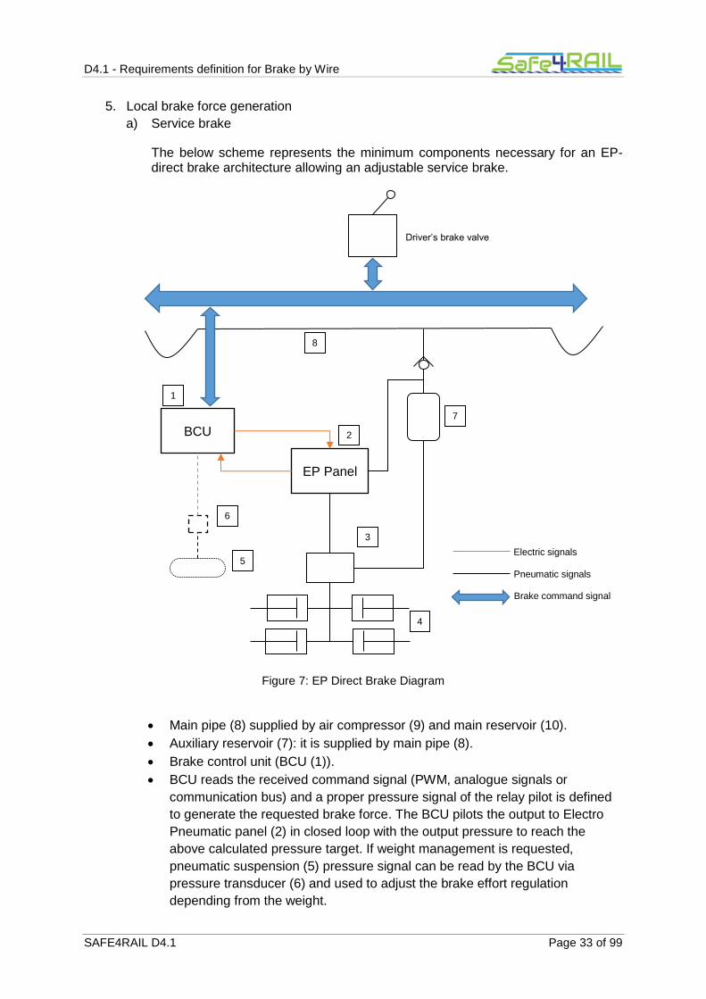
The below scheme represents the minimum components necessary for an EP-direct brake architecture allowing an adjustable service brake.
Figure 7: EP Direct Brake Diagram
Main pipe (8) supplied by air compressor (9) and main reservoir (10).
Auxiliary reservoir (7): it is supplied by main pipe (8).
Brake control unit (BCU (1)).
BCU reads the received command signal (PWM, analogue signals or
communication bus) and a proper pressure signal of the relay pilot is defined
to generate the requested brake force. The BCU pilots the output to Electro
Pneumatic panel (2) in closed loop with the output pressure to reach the
above calculated pressure target. If weight management is requested,
pneumatic suspension (5) pressure signal can be read by the BCU via
pressure transducer (6) and used to adjust the brake effort regulation
depending from the weight.
BCU
EP Panel
8
1
2
7
5
3
4
6
Electric signals
Pneumatic signals
Brake command signal
Driver’s brake valve

D4.1 - Requirements definition for Brake by Wire
SAFE4RAIL D4.1 Page 34 of 99
Electro-pneumatic panel (EP panel) (2): it is supplied by auxiliary reservoir via
pressure regulator. By means of brake and release solenoid valves controls
the output pressure. A pressure sensors provide to the BCU the feedback
signal. The valve control principle is “energize to apply”, to avoid that in case
of power off or failure of the BCU/solenoid valves there is an automatic brake
application. This is against one of the safety requirements at the base of the
automaticity (energize to release), but reduce the impact of single failures.
Relay valve (3): it amplifies the pilot pressure signal of the EP panel to supply
all the brake cylinders (4). It can be weight dependent in alternative to the load
regulation by electronics.
Brake cylinders (4).
a) Emergency brake
The described structure of the service brake architecture doesn’t fulfil the safety requirement of continuity, automaticity and energy to release. Additionally the not safe architecture of the service brake local management could affect the emergency brake application, by the parallel undue venting of the relay valve pilot.
The emergency brake command line is therefore used to operate on a second brake force generation system bypassing the service brake force generation system.
Following solutions could be applied depending from the emergency brake command signal transmission system used.
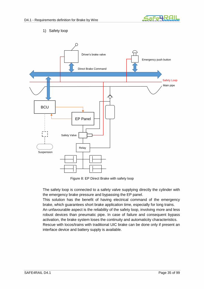
D4.1 - Requirements definition for Brake by Wire
SAFE4RAIL D4.1 Page 35 of 99
1) Safety loop
Figure 8: EP Direct Brake with safety loop
The safety loop is connected to a safety valve supplying directly the cylinder with
the emergency brake pressure and bypassing the EP panel.
This solution has the benefit of having electrical command of the emergency
brake, which guarantees short brake application time, especially for long trains.
An unfavourable aspect is the reliability of the safety loop, involving more and less
robust devices than pneumatic pipe. In case of failure and consequent bypass
activation, the brake system loses the continuity and automaticity characteristics.
Rescue with locos/trains with traditional UIC brake can be done only if present an
interface device and battery supply is available.
Relay
BCU
EP Panel
Safety Loop
Main pipe
Safety Valve
Suspension
Direct Brake Command
Driver’s brake valve
Emergency push button

D4.1 - Requirements definition for Brake by Wire
SAFE4RAIL D4.1 Page 36 of 99
2) Brake pipe
Figure 9: EP Direct Brake with brake pipe
The distributor connected to the brake pipe pilots a second input of the relay valve
applying the emergency brake pressure at the cylinder whatever is the pilot
pressure of the direct brake EP panel. The distributor can be:
UIC distributor controlled by brake pipe
Not UIC distributor controlled by brake pipe
Generally a not UIC distributor is used for economical reason, considering that the
service brake is done by EP direct brake.
This solution has the advantage to have a robust and reliable emergency brake
command and fully pneumatic back-up brake. Rescue can be done by locos/train
with traditional UIC brake system.
Faster emergency brake application can be achieved by direct service brake
parallel application, but not in a safe way, so the advantages on the brake
performance of the train cannot be used.
Relay
BCU
EP Panel
Main pipe
Brake pipe
Distributor
Suspension
Direct Brake Command
Driver’s brake valve Emergency push button

D4.1 - Requirements definition for Brake by Wire
SAFE4RAIL D4.1 Page 37 of 99
3) Safety loop + brake pipe
Figure 10: EP Direct Brake with safety loop and brake pipe
This is the sum of the two above solutions.
It is redundant in terms of components (double brake system on board), but allows to join the advantages of the two systems, compensating one system the limits of the other one.
Basically in Europe the EP direct brake architecture implements both safety loop and not UIC distributor.
The inexhaustibility requirement is guaranteed by the refilling of the auxiliary reservoir by main pipe and by proper monitoring of one or both of them, as per not UIC indirect pneumatic brake described in §1.1.6.1.2.
The electronic control of pilot pressure gives a high flexibility in friction service brake control, allowing:
a) much more precise brake force distribution among the vehicles to optimize the use of
adhesion,
Relay
BCU
EP Panel
Safety Loop
Main pipe
Brake pipe
Distributor
Safety Valve
Suspension
Direct Brake Command
Driver’s brake valve Emergency push button

D4.1 - Requirements definition for Brake by Wire
SAFE4RAIL D4.1 Page 38 of 99
b) maximize the use of ED brake by proper blending logic,
c) possibility to have continuous speed dependent braking forces regulation .
What in UIC pneumatic brake system requires additional devices and control line, with EP direct brake can be done by software. The presence of control unit amplifies the monitoring possibility as well. The control units and software normally used in EP direct brake has maximum SIL2 certification.
In case load dependent brake force is requested in emergency, relay valves with load signal management are necessary (see Figure 11).
Figure 11: EP Direct Brake with load dependent relay valve
Rescue function can be more complicated for direct brake architecture: if for UIC brake it is sufficient one air connection to rescue a faulty train, transmitting to it the brake command and the energy to brake, for direct brake there is not an uniformity of brake command type, electric energy is necessary and pneumatic connection is in any case necessary to transmit
Load dependent Relay
BCU
EP Panel
Safety Loop
Main pipe
Brake pipe
Distributor
Safety Valve
Suspension
Direct Brake Command
Driver’s brake valve Emergency push button

D4.1 - Requirements definition for Brake by Wire
SAFE4RAIL D4.1 Page 39 of 99
the braking energy. Furthermore it should be possible to rescue trains with direct brake by locomotives that are equipped with UIC brake. For this reason it is allowed by legislation (see [1] §4.2.4.10) to rely on low voltage availability (to provide the necessary electric energy for direct brake control) and to have interface device between brake command given by brake pipe and brake command according the rescued train architecture.
Conclusion:
The following minimum safety requirements prescribed by [5] (see §1.1.3.1) are satisfied:
Continuity,
Automaticity
Inexhaustibility
Energise to release brake command line
decentralized brake actuators, developing the brake force using locally stored energy
proven design components
The continuity is guaranteed by the daily check of the correct application of the brake, till the end of the train, done by the safety loop and/or the brake pipe; the automaticity is guaranteed by the safety loop and/or the brake pipe and its supply; inexhaustibility is guaranteed by monitoring of main pipe; the energize to release brake command is guaranteed by the indirect concept of safety loop and/or the brake pipe.
1.1.6.2 Dynamic brake
The dynamic brake introduced in this chapter is the electrodynamic brake or the hydrodynamic brake. The eddy current brake is not considered. Detailed description of electro-dynamic brake system or hydrodynamic brake system is out of the scope of this document.
Dynamic brake is a system able to transform the kinetic energy of the train into heat or electric energy. To do that there are several solutions, but all of them require generally an electrical supply.
The dynamic brake systems are more limited in terms of braking power respect the friction brake.
Energy dissipation of friction brake is linked to the heat transmission between the disc/wheel and the air and the resistance of the braking couple (disc/wheel and pad) to the high temperature.
The power of dynamic brake is limited by the electrical/hydraulic components, which are dimensioned for a maximum power. For this reason the curve force versus speed of dynamic brake has normally the form shown in [10] §5.3.2.1-2 (see Figure 12 and Figure 13): constant force till a certain speed (maximum force), equi-power curve after a certain speed.

D4.1 - Requirements definition for Brake by Wire
SAFE4RAIL D4.1 Page 40 of 99
Figure 12: Characteristic curve for electrodynamic brake force
Figure 13: Characteristic curve for fluid retarder braking force
The maximum power of electrodynamic brake is limited by regenerative mode or rheostatic mode in different way:
a) regenerative mode: the power is linked to the catenary voltage limits.
Note: harmonics disturbances generation is also a constraint leading to immediately
stop regenerative mode in case limits are exceeded.
b) rheostatic mode: the power is linked to the dimensioning of rheostat, its heat capacity
adsorption and ventilation availability.
The same train can have different dynamic brake forces characteristics depending from the operative mode of the ED brake active.
The architecture controlling the dynamic brake can be again traced back to the scheme at §5.2 of [7].
1. Energy supply necessary to generate the braking force
FBED
V4 V3 V
2 V
1 V
max
FBED max
FBFR
V2 V
1
Vmax
FBFR max
V0

D4.1 - Requirements definition for Brake by Wire
SAFE4RAIL D4.1 Page 41 of 99
In case of dynamic brake the energy necessary to generate the braking force is the electrical energy necessary to maintain operative the traction or the hydraulic transmission system, to manage the energy dissipation (excitation of the motors, fans, pumps, etc…) or transmission to the catenary. This energy is taken from catenary in case of electric train or by the engine in diesel trains.
The electric supply needed can be at low continuous voltage or/and at medium alternate voltage.
2. Local energy store
The low voltage batteries are the local energy store for low continuous voltage devices and can become store also for medium alternate voltage if inverters are provided transforming the continuous voltage into alternate voltage.
Valid alternative to inverter for medium voltage supply is to use the kinetic energy of the train to generate the medium voltage energy, so in principle the mass of the train represent the local energy store for medium alternate voltage.
The electrodynamic brake can make it very easily, and without additional devices using electric motors as generators while braking (or better, thanks to braking).
This characteristic is important for rescue condition, because the energy from locomotive to rescued train is transferred as mechanical energy by the coupler (energy generating movement of the train) and transformed into electric energy by the dynamic brake system of the rescued train. It is not necessary any cable.
This characteristic makes in principle the electrodynamic brake intrinsically inexhaustible, but this characteristic is subjected to the reliability of much more components than in UIC brake, where the inexhaustibility is practically guaranteed only by UIC distributor or triple valve.
3. Brake command generation
a) Service brake
Dynamic brake request can be part of the overall train retardation request presented in §1.1.6.1. (indirect brake) and §1.1.6.1.3 (direct brake).
It can be controlled also separately by proper lever on the desk controlling traction and dynamic brake. Normally this request is managed by bus.
b) Emergency brake
Any of the devices commanding the emergency brake can generate a dynamic brake command, if foreseen.
They operate on automatic brake system command line.
4. Brake command transmission
a) Service brake
The most common way to transmit the (adjustable) dynamic brake force is the bus. Where PWM signal is used for EP-direct brake the same signal is used by dynamic brake.
b) Emergency brake
Main emergency brake command lines are used for the transmission of the emergency brake request: safety loop and/or brake pipe.

D4.1 - Requirements definition for Brake by Wire
SAFE4RAIL D4.1 Page 42 of 99
Due to the above described characteristics of these command lines, the continuity, automaticity and “energize to release” properties of the command are guaranteed.
5. Brake force generation
Dynamic brake unit is in charge of the transformation of the command into braking
force. The devices involved are several:
i. Traction control unit
ii. Traction inverter
iii. Filters
iv. Motors
v. Coolers
vi. Rheostat
vii. Pantograph
viii. etc...
It is out of the scope of this document the description of the traction system.
a) Service brake
The brake force is proportional to the brake command (generally given as
percentage of the available brake force).
The typical signals provided by traction unit on the bus during braking are the
available effort (based on the active mode or failure presents limiting force or
power) and the real effort. Based on this data the unit in charge of the blending is
able to define the distribution of the train retardation force between the available
braking systems.
b) Emergency brake
Each brake force generator unit is connected to the safety loop or to normally
open pressure switches on brake pipe in order to receive, in a hardware way, the
emergency request and activate the traction cut off and emergency brake force
management.
If dynamic brake is not used in emergency, above signals are used at least for
traction cut off.
The management of emergency brake forces generation is generally different
from service brake, in particular regarding blending. The value of braking effort
which has to be guaranteed depends on the safety analysis on the whole ED
brake system.
Conclusion
The following minimum safety requirements prescribed by [5] (see §1.1.3.1) are satisfied:
continuity,
automaticity,
inexhaustibility,
energise to release brake command line,
decentralized brake actuators,
proven design components.

D4.1 - Requirements definition for Brake by Wire
SAFE4RAIL D4.1 Page 43 of 99
The continuity is guaranteed by the safety loop and/or the brake pipe and their daily check, the automaticity by the safety loop and/or the brake pipe and its supply, inexhaustibility by the kinetic energy of the train, the energize to release brake command by the indirect concept of safety loop or/and the brake pipe.
1.1.6.3 Magnetic track brake
Magnetic track brake (MTB) represents a further contribution to emergency brake force to be used to have better performances also with low adhesion, allowing shorter distance between trains.
MTBs, in most of the cases, are of the type in upper position. It means that the command of the MTB is composed of two actuations, both essential for the correct application of the brake:
lowering of the shoes;
energizing of the coils generating the magnetic field.
The first action is done by pneumatic actuators, the second by electric circuits.
The systems in charge of these two actions shall guarantee the safety requirements specified in [5].
Here below the normal control system used for MTB is described.
1. Energy supply necessary to generate the braking force
a) Shoes lowering
The pneumatic energy is taken by the main pipe, supplied by the compressor.
In general when MTB is applied and UIC brake system is used for friction brake, the continuity of the main pipe is tested at the beginning of the service in addition to the normal test of the brake (continuity, brake and release of all vehicles), because the main pipe is not relevant for UIC brake system.
If EP-direct brake is used, the monitoring logic guarantees both the inexhaustibility and the MTB energy supply.
b) Coils energizing
The electric energy to supply coils is taken by catenary or by generator controlled by diesel motor.
2. Local energy storage
a) Shoes lowering
A dedicated reservoir for MTB supply is provided on each vehicle where MTB is fitted protected by check valve.
b) Coils energizing
The energy comes from batteries and the coils are supplied at low continuous voltage.
The inexhaustibility is given
for pneumatic path, by the main pipe continuity checked at the beginning of the
service or by the main pipe monitoring;

D4.1 - Requirements definition for Brake by Wire
SAFE4RAIL D4.1 Page 44 of 99
for electric path, by battery circuit diagram assuring the direct supply of coils by
main low voltage line and and its monitoring (minimum battery voltage shall
guarantee correct shoes force application).
3. Brake command generation
Any of the devices commanding the emergency brake (see §1.1.3.2), command the
application of the MTB as well, if present. They operate on automatic brake system
command line. Additionally, a voluntary command by drivers sometime is
implemented as well.
4. Brake command transmission
Main emergency brake command lines are used for the transmission of the
emergency request: safety loop and/or brake pipe.
Due to the above described characteristics of these command lines, the continuity,
automaticity and “energize to release” properties of the command are guaranteed.
5. Brake force generation
The emergency brake command energizes a solenoid valve feeding cylinders in
charge to lower the shoes. The position of the shoes is monitored to detect any failure
at the lowering system during braking.
The command energizes the coil circuit which generates the magnetic field
responsible for the attraction force between shoes and rail. The current adsorption of
the MTB is monitored during the braking as well. The circuit diagram has to be done
in accordance to indication of [22].
Conclusion:
The following minimum safety requirements prescribed by [5] (see §1.1.3.1) are satisfied:
continuity,
automaticity,
energise to release brake command line,
decentralized brake actuators, developing the brake force using locally stored energy,
proven design components.
The continuity is guaranteed by the safety loop and/or the brake pipe and their daily check; the automaticity by the safety loop and/or the brake pipe and its supply; inexhaustibility by the main pipe pressure and battery voltage monitoring and daily continuity check; the energize to release brake command by the indirect concept of safety loop or/and the brake pipe.
1.1.6.4 Parking brake
Actually there are two types of brakes performing the function of immobilizing the train in standstill for an unlimited period of time. Both of them guarantee the application of the force by special type of brake actuators at bogie level.
1) Spring parking brake
It uses pneumatic brake actuators (cylinders or what else) having an additional portion,
operating on the cylinder piston in parallel to the service pneumatic portion, working
with an “energize to release” principle. Thanks to preloaded spring present inside, it
applies a force to the pad in case of missing air supply, it reduces the force to the pad

D4.1 - Requirements definition for Brake by Wire
SAFE4RAIL D4.1 Page 45 of 99
proportionally with the increase of the supply pressure till to reach complete release
when the pressure reaches the pre-set value (depended from the spring preload).
2) Hand brake
It uses pneumatic brake actuators (cylinders or the like) having an additional
mechanical portion (rigging), operating on the cylinder piston in parallel to the service
pneumatic portion. This additional portion is commanded by an external mechanical
force applied by command cable connected to a spindle operated by a gear drive which
is moved by a hand wheel.
Figure 14: Hand brake equipment acting on disc
The hand brake is a pure manual system, used mainly on coaches. For this reason has no relevance with the scope of this document. The document focuses only on spring parking brake command architecture.
Due to its characteristics the spring parking brake architecture analysis considers separately the control and the actuators.
1. Energy supply necessary to generate the braking force
a) Control
Pneumatic energy can be provided from compressor via main pipe or via brake pipe. Electric energy from pantograph or engine via battery chargers.

D4.1 - Requirements definition for Brake by Wire
SAFE4RAIL D4.1 Page 46 of 99
b) Actuators
Being the scope of the brake to immobilize for indefinite time the train, this type of brake cannot be linked to an external supplier of energy. Spring parking brake actuator have always only local energy store available.
2. Local energy store
a) Control
The energy stores are the auxiliary reservoir and the main pipe for actuator release and the batteries for command generation.
The auxiliary reservoir and the main pipe can both supply the parking brake control line (for solution with voluntary application) in order to don’t link the parking brake availability to the service brake one (isolation of service brake vent the auxiliary reservoir). At the same time the supply by auxiliary reservoir allows to control the parking brake also in case only the brake pipe is available. In such a case the actuator shall have a release pressure lower than 5 bar.
Thanks to the intrinsic inexhaustibility of the actuators, the control doesn’t need the properties of inexhaustibility.
b) Actuators
The local braking energy store is given by the preload of the spring present in the actuator. It means that the energy is available not at single vehicle level, but at single actuator level.
The inexhaustibility is intrinsic.
3. Brake command generation
a) Control
The command can be voluntary or automatic.
Voluntary command.
Single electric signal: energize to release, de-energize to apply
(monostable logic).
Two different electric signals (apply and release) which combination gives
the local apply or release command according to a “bi-stable” logic.
COMMAND STATUS Apply Release
No change 0 0
Apply 1 0
Release 0 1
No change 1 1
This type of command must be energized to be applied, but has the
advantage to be reliable because less affected by undue “apply” signal
generation due to cabling/component failures or in case of a lack of
energy. Control logic of bi-stable command has to be defined according to
safety principles (for example the “apply” signal is permanent on until a
release signal is not given, release signal is time limited, etc…)
This type of command is used in case the local brake force generation is
done by a pneumatic bi-stable valve (see below).
Automatic command:

D4.1 - Requirements definition for Brake by Wire
SAFE4RAIL D4.1 Page 47 of 99
by control circuit at switching off of the driver’s desk, to be used in case of
voluntary bi-stable command configuration;
at switching off of driver’s desk or at battery supply cut off (this is intrinsic
in the voluntary single command configuration).
Risk analysis shall be considered in defining the command logic. Generally release command is possible only from enabled driver’s cab, apply command is generally inhibited during running.
b) Actuator
Automatic apply command is naturally given by the lowering of the supply pressure due to leakages in auxiliary reservoir, thanks to the actuator working principle “energize to release”.
This type of command has the great characteristic to be local, always available (it is intrinsic in the inverse working principle of the actuator), complementary with the service brake.
It means that soon or later it will apply due to the leakages. The consequence is that it is sufficient to apply the service brake to guarantee the immobilization of the train for indefinite time, because when the service brake starts to release due to leakages the parking brake starts to apply.
This characteristic makes the spring parking brake intrinsically automatic and for this reason the bi-stable command is acceptable even if it uses energy to apply voluntary command.
That’s why the single failure to be considered for parking brake performance is the failure of the single actuator (see [5] §5.11.4).
This characteristic allows also solution without parking brake control system. The
application is only naturally given by leakages.
4. Brake command transmission
The parking brake command transmission, valid only for voluntary applied parking
brake, is done generally by:
train wires,
bus signals.
The continuity is checked by testing at beginning of the service the correct application/release of parking brake by voluntary command.
The correct application can be monitored by:
the permanent monitoring system of the parking brake status (see below);
traction test: with parking brake applied a certain effort shall be given by traction
and the train shall not move.
In both cases risk analysis is needed about wrong diagnostic result.
5. Brake force generation
The brake force is applied if the actuators inlet port of parking brake is vented, the
brake force is released if the same port has a pressure higher than the release one.
The brake force can be released also with vented port by manual operation on the
actuator. This operation shall be done after isolation of the pneumatic supply of the
actuator. Differently from service/emergency brake, the isolation generates
automatically parking brake application.

D4.1 - Requirements definition for Brake by Wire
SAFE4RAIL D4.1 Page 48 of 99
On train without voluntary command, there is a direct connection between auxiliary
reservoir and the actuator’s ports.
Control architecture of voluntary application configuration depends from the type of
command (mono-stable or bi-stable).
The control is generally at vehicle level, controlling one or two bogies; isolation at
vehicle or bogie level depends from the dimensioning calculation. Vehicle control and
bogie isolation is a quite frequent configuration.
The monitoring of parking brake application status or isolation is done by pressure
switches and micro-switch on isolation device.
a) Control with mono-stable logic
The apply/release command is transformed into pressure piloting the actuator by
a mono-stable valve.
Figure 15: Parking brake – Control with mono-stable logic
The advantage of this solution is the automatic application at train switching off, only one command line, simpler valve.
Pressure sensor
Service Brake
Control
Parking brake portion of the actuator
Parking brake release command line
Main pipe

D4.1 - Requirements definition for Brake by Wire
SAFE4RAIL D4.1 Page 49 of 99
b) Control with bi-stable logic
Figure 16: Parking brake – Control with bi-stable logic
The advantages of this type of control, as written before, is the reliability. The bi-
stable command is also more robust in terms of resistance to fire, and
consequently easier to fulfil the running capability requirement.
Additionally the valve can be controlled manually, if the function is provided at
valve level.
Conclusion:
The minimum safety requirements required by [5] (see par. 1.1.3.1) are guaranteed.
continuity,
automaticity,
inexhaustibility,
energize to release brake command line,
decentralized brake actuators, developing the brake force using locally stored energy,
proven design components.
The continuity is given by the monitoring of the correct application of the actuators and/or daily test; the automaticity, inexhaustibility and energize to release principle are given by brake actuator.
Pressure sensor
Service Brake
Control
Parking brake portion of the actuator
Parking brake release command line
Main pipe
Parking brake apply command line
D4.1 - Requirements definition for Brake by Wire
SAFE4RAIL D4.1 Page 50 of 99
1.1.6.5 Brake test
Brake test is a relevant function that has the objective to verify the continuity of the brake command and efficiency of the local force generation systems, as often mentioned in previous chapters.
It can be done in two ways.
Manually: an operator going along the train and check that the command arrive till the
end of the train and that all the vehicles apply the different type of braking forces (with
exception of dynamic brake).
Automatically: TCMS performs the same test by proper sensors installed on the
systems.
Systems involved in the test are:
service and emergency brake;
parking brake;
WSP.
Additionally, permanent monitoring has to be guaranteed to identify single failures on the above systems and on the remaining braking systems that is not possible to test in standstill (i.e. dynamic brake).
On new trains all above functions are generally performed by the TCMS and bus signals. To use the TCMS and bus, brake test shall comply with the proven in use requirement. For this reason, often, manual and automatic tests are executed in parallel for a predefined period at the beginning of commercial service to assess the “service proven” characteristic of TCMS control.

D4.1 - Requirements definition for Brake by Wire
SAFE4RAIL D4.1 Page 51 of 99
1.2 Limits of existing brake systems
1.2.1 Service/Emergency brake
Considering the purpose of the braking system (§1.1.2), the functional and safety requirements (§1.1.3), the requested performances in terms of deceleration, used adhesion level, jerk and equivalent time (§1.1.4), the EP direct brake architecture as described in §1.1.6.1.3 Figure 11 (direct brake + indirect brake) is able to fully comply with the emergency brake safety requirements. Furthermore, EP direct brake architecture allows in service brake to optimize the distribution of the energy between the different types of brake (cross blending between friction and dynamic) and the distribution of adhesion, to reduce the brake application time to the minimum possible in relation to the pneumatic system capability at vehicle level, to apply load or/and speed dependent brake forces.
The solution takes the advantages of both architectures in terms of safety, reliability and trains coupling (indirect brake), flexibility and monitoring (direct brake).
Limits are still present on this system mainly in terms of complexity, cost and specific functions related to emergency brake. These limits are listed (not exhaustive) below.
1) Complexity
1.1) Necessity of air supply (energy supply).
1.2) Several parallel braking system (direct and indirect friction brake, dynamic
brake, MTB).
1.3) Several parallel control and monitoring systems (TCMS; brake, WSP,
Passenger alarm, Traction Control units; electrical circuit, pneumatic device
like gauges).
1.4) Several control units distributed along the train.
1.5) Electrical circuits with several interfaces, connections and devices (lowering
the reliability).
2) Cost of the system
2.1) Two braking system:
EP direct panel and distributor;
safety loop and brake pipe;
electric driver’s brake valve with pneumatic portion.
2.2) Air production systems (compressor and drier).
2.3) Cost of control units/ pneumatic devices.
2.4) Piping and its installation(weight impact also).
2.5) Maintenance cost of pneumatic devices (periodical replacements of not
metallic parts), air production unit maintenance (drier and compressor).
3) Blending management
Reduced capability of managing the blending during emergency brake.
4) Speed dependent friction brake force in emergency
It is not possible to have a continuous speed dependent friction brake force in
emergency.
5) Load dependency in emergency
It cannot be guaranteed by electronics but only by more complex and expensive relay
valve.
6) Dynamic brake management in emergency
Currently the use of dynamic brake in emergency is limited by safety reasons.
Traction chain is complex and often the safety analysis reduces or inhibits completely

D4.1 - Requirements definition for Brake by Wire
SAFE4RAIL D4.1 Page 52 of 99
the possibility to consider the whole dynamic braking power during emergency
braking. This leads in an over-dimensioning of the friction braking system.
7) WSP optimization
The WSP is a stand-alone system, active on single vehicle without interaction with the
other vehicles, the train and the brake system itself.
1.2.2 Parking brake
Considering the purpose of the immobilization system (§1.1.2), the functional and safety requirements (§1.1.3), the requested performances (§1.1.4) the existing solution fulfil all the requirements with a simple and very reliable solution.
The monitoring system of the voluntary application architecture it requires often, especially when manual release status has to be identified by monitoring system, more complex control logic and sensors (also integrated in the actuators) which can reduce the reliability of the system. However, this is not affecting the architecture of the control and monitoring, which is normally already done by bus architecture on new trains using as interface the BCUs for monitoring and TCMS and train bus for command.

D4.1 - Requirements definition for Brake by Wire
SAFE4RAIL D4.1 Page 53 of 99
1.3 Possible Innovative solutions to overcome the limits
An innovative solution shall have as driving principles the compliance with TSI and the basic requirements described in §1.1.3.1:
a) continuity
b) automaticity
c) inexhaustibility
d) energize to release brake command line
e) decentralized brake actuators, developing the brake force using locally stored energy
f) proven design components
g) running capability
The solution shall take into account the following functions which could impact the definition of the new architecture:
h) redundant devices to initiate the emergency brake;
i) redundant components on emergency brake electrical command chain;
j) priority of emergency brake on any other brake and release command;
k) safe traction cut off at emergency triggering;
l) load and speed dependent brake force regulation in emergency (to maximize the use
of adhesion);
m) dynamic brake application in emergency with active blending (to maximize the effect
on performances and minimize the number of actuators/disc of friction brake system);
n) back up brake command: necessary to guarantee sufficient availability of the brake
system (operative impact)
o) integration in the new architecture of nowadays standalone functionalities like
monitoring system, wheel slide protection and passenger alarm.
The new solution shall be assessed according to the safety requirements in§1.1.5.
The objectives in studying an innovative solution are to overcome the limits of existing solution listed in par. 1.2 and to reduce the cost at LCC level.
This second objective could be reached by an architecture reducing as much as possible:
pneumatic component;
electronics;
piping and cabling;
friction brake use (reduced pad wear).
The innovative solution could be oriented versus:
a completely innovative system, compliant to the above mentioned requirements,
implemented by means of new components and architectures which allow to
overcome the limits;
a simplification of existing architecture by the introduction of new control system that
is able to manage the existing brake force generation devices.
Even if plausible, the first approach is here only mentioned but not further investigated because dependents from the development of new force generation systems/devices while the objectives of the study is more related to the integration with the new train control and management system.

D4.1 - Requirements definition for Brake by Wire
SAFE4RAIL D4.1 Page 54 of 99
1.3.1 Service/emergency brake
The goal of the innovative system is to use as much as possible the bus technologies and electronics control to overcome the above limits.
Possible architectures should be defined starting from the basic architecture components defined at §5.2 of [7] (see also above chapter §1.1.6):
energy supply;
brake command generation;
brake command transmission;
local energy store;
local brake force generation.
Energy supply system
The main energy supply (both pneumatic and electric system) can be guaranteed, as today, by catenary/diesel engine or by the kinetic energy of the train. Thanks to local energy store the energy supply has not impact on safety.
Brake command generation
The device generating the brake command listed in §1.1.3.2, 1.1.3.3 and 1.1.3.4 should become only electrical, to be interfaced with bus system or should integrate internally the interface with bus system.
Brake command generation device shall be designed to comply with the following requirements among the mentioned in §1.3:
a) continuity;
d) energize to release brake command line;
f) proven design components
g) running capability
h) redundant devices to initiate the emergency brake
i) redundant components on emergency brake electrical command chain;
n) back up brake command: necessary to guarantee sufficient availability of the brake system (operative impact)
and will influence the assessment of hazard specified in §1.1.5 cl. 1).

D4.1 - Requirements definition for Brake by Wire
SAFE4RAIL D4.1 Page 55 of 99
Brake command transmission
An analysis of the possible improvements related to brake command transmission is here performed individually on service brake and emergency brake.
a) Service brake
Service brake command shall be adjustable command.
It is not subjected to safety requirements.
The service brake command requires an high integration between different brake system.
The most efficient way is to manage it at train level, by cross blending rules which allow to
distribute brake forces between braking systems and vehicles to guarantee constant
performances also in case of failure of single braking apparatus.
Note: the signals generated by brake command generation devices present on the train shall
be transformed by TCMS into a brake force target for each single vehicle/brake system. Here
this function is for convenience considered part of the brake command transmission function,
even if in principle is part of the command generation, because it is strictly linked to the
architecture of the transmission.
b) Emergency brake
The emergency command is a not adjustable brake force command (on/off), which shall
assure the application of a predefined brake force to the train (speed and/or load dependent
force, if needed). The emergency brake command is subjected to safety requirements.
The antivalent characteristics of service and emergency brake (adjustable/not adjustable; not
safe/safe) could suggest different command transmission systems for service and
emergency brake, as in the existing solution.
Nevertheless, the advantages of service brake (adjustable force, cross blending
management) could be interesting for emergency brake as well (to overcome the limits in
§1.2.1), inducing to suppose the opportunity of a safe service brake which performs the
function of emergency brake as well. Additionally a single brake command transmission
system for both service and emergency could be an improvement in terms of cost.
Above considerations can generate different architectures of the brake command
transmission, which can also influence the local force generation system.
1) Central management of the brake command
The TCMS is in charge of collecting demands from the brake command generation devices, elaborate them and transmit the relevant commands to every vehicle by bus.
1.1) Different “layers” of brake command transmission
Traction and service brake commands and all functions not related to safety
are managed by normal logic and protocols.
Emergency brake command and other functions related to safety are
managed by high integrity level logics and protocols

D4.1 - Requirements definition for Brake by Wire
SAFE4RAIL D4.1 Page 56 of 99
Figure 17: Innovative solution – Brake command transmission
This solution would overcome limits 1.3), 1.4) and 1.5).
This kind of central management of the command is already used for not safe
functions (Traction, Service brake) and for Passenger Alarm system (low safety
integrity level required).
What is missing is an emergency brake with the improvements described above
(blending management at train level, etc…) and commanded by means of bus
signals/messages.
It should comply with the following requirements:
a) continuity
b) automaticity
c) inexhaustibility
d) energize to release brake command line
f) proven design components
g) running capability
i) redundant components on emergency brake electrical command chain;
j) priority of emergency brake on any other brake and release command;
k) safe traction cut off at emergency triggering;
l) load and speed dependent brake force regulation in emergency (to maximize the use of adhesion)
m) dynamic brake application in emergency with active blending (to maximize the effect on performances and minimize the number of actuators/disc of friction brake system)
n) back up brake command: necessary to guarantee sufficient availability of the brake system (operative impact)
o) integration in the new architecture of nowadays standalone functionalities like monitoring system, wheel slide protection and passenger alarm.
Traction, Brake command devices
TCMS
Vehicle 1 Vehicle 2 Vehicle n

D4.1 - Requirements definition for Brake by Wire
SAFE4RAIL D4.1 Page 57 of 99
and will influence the assessment of hazards specified in cl. 1), 4), 5) and 7) of
§1.1.5.
This architecture requires that at local level the force generation system are able to manage with needed safety level the safety relevant command received by bus.
The further evolution could be that TCMS manages directly the traction and brake local force generation by means of new generation of actuators and sensors able to interface to the bus. In this case BCU and TCU installed on single vehicle would be no more present.
This architecture is very interesting since it would allow to centralize the control of the WSP system. In this way the reference speed management could be performed at train level, much more accurate than the actual one built on the base of only 4 speed sensors, and also to have management at train level of the brake force distribution based on the real adhesion available and energy dissipation capability of the actuators (at least for service brake). Centralization of the WSP requires an architecture (bus, protocols and logics) with low latency and fast reaction time. If not possible, at least the reference speed can be managed at train level.
1.2) Central performance monitoring
It applies a concept used by signalling: train can run at a certain speed if the
guaranteed stopping distance of the train at that speed is available, if not an
emergency brake is applied.
This concept applied to the emergency brake management means the use of the
maximum service brake force (including cross blending), with low integrity level, to
obtain the emergency brake performances by a not safe system and monitor in a
safe way the correct force application. If the force application is not correct, the
system shall switch to safe emergency brake system with high integrity level
application.
The architecture would be similar to the above one, with the advantage of a
reduced complexity in term of safety signal management (less interfaces, less
signals, less logics), not only at train level, but also at local force generation level.
It can be used when the possibility to have at local level safe dynamic brake force
generation is impossible or too much expensive, but it is preferable to use it to
don’t stress to much the friction brake system (i.e. for high speed trains) or the
management of cross blending at train level requires a too heavy management of
the safety bus
It has the disadvantage that the safe brake force generation systems shall be
dimensioned for the worst case and that the guaranteed emergency brake
performances will not reach the level of the solution in cl. 1.1).
The control of correct application can be based on the verification of the pressure at the cylinders or the deceleration level of the train.
Pressure control: high integrity level pressure sensors to be installed on
brake cylinder supply line and, if load management is foreseen in
emergency, also on air suspension.
Deceleration level: high integrity level device monitoring the train
performances (electronics + speed sensor) or safe interface with signalling

D4.1 - Requirements definition for Brake by Wire
SAFE4RAIL D4.1 Page 58 of 99
system or the signalling system itself performing this function and providing
the emergency brake application signal on the bus.
Solution based on deceleration monitoring done by signalling system is preferable
because it is an already installed high integrity level device.
The use of deceleration level principle shall manage the slope information to
consider the gravity force effect on train retarding force and consider aerodynamic
force as well (function of the speed)
Figure 18: Innovative solution – Brake command transmission & signalling
This architecture should comply with the same requirements listed above and
influences same hazards.
2) Local Management of the emergency command
The local management of the emergency command is an alternative to solution in cl. 1.2) having the goal to have a lower number of safe signals to be managed at train level bus.
The train level bus has only the goal to transmit to the single local devices (brake units, traction units, etc…) the emergency command. This signal is managed locally by the brake force generation system.
The brake command on train bus shall be in charge of the following requirements mentioned in cl. 1.1):
a) continuity
b) automaticity
c) inexhaustibility
d) energize to release brake command line
f) proven design components
g) running capability
i) redundant components on emergency brake electrical command chain;
j) priority of emergency brake on any other brake and release command;
Traction, Brake command devices
TCMS
Vehicle 1 Vehicle 2 Vehicle n
Signalling

D4.1 - Requirements definition for Brake by Wire
SAFE4RAIL D4.1 Page 59 of 99
n) back up brake command: necessary to guarantee sufficient availability of the brake system (operative impact)
o) integration in the new architecture of nowadays standalone functionalities like monitoring system, wheel slide protection and passenger alarm.
and will influence the assessment of hazards specified in cl. 1), 4), 5) and 7) of §1.1.5.
The brake force generation system shall be in charge of the remaining ones linked to emergency:
k) safe traction cut off at emergency triggering;
l) load and speed dependent brake force regulation in emergency (to maximize the use of adhesion)
m) dynamic brake application in emergency with active blending (to maximize the effect on performances and minimize the number of actuators/disc of friction brake system)
Of course the blending in this case can be managed only at local level.
Local energy store
The local energy store remain the batteries and the auxiliary reservoir.
Local force generation system
The starting point architecture, still based on pneumatic solution, for local force generation system is the EP direct brake + Safety loop (see 1.1.6.1.3).
This architecture has already removed the brake pipe, the pneumatic driver’s brake valve and the distributor, removing part of the limits in clause 1) and 2), with following advantages:
the only pneumatic device which could remain on the desk are the gauges
(necessary to check the brake status in case of missing electrical power supply);
available space below the driver desk;
one 25 mm inner diameter pipe less to be installed along the train;
less pneumatic hoses between the vehicles;
one component (distributor) less at vehicle level;
simpler relay valve (single pilot).
The main limits of this solution are the ones related to the emergency brake:
pneumatic bypass of EP panel needed in emergency (safety valve) due to not safe
management of the brake and release valves of the EP module by BCU;
load dependent relay valve necessary to have load dependent emergency brake
force;
reliability of the electric system managing emergency brake safety loop;
loss of the continuity and automaticity characteristics in case of bypass safety loop;
not possible to optimize blending in emergency brake like in service brake due to not
safe enough electronics;
impossibility to have speed dependent friction brake force due to not safe enough
electronics.

D4.1 - Requirements definition for Brake by Wire
SAFE4RAIL D4.1 Page 60 of 99
The local force generation system should receive the emergency brake command by bus and should manage it accordingly with the proper safety integrity level.
Improvements for local pneumatic brake system could be:
apply and release valves able to be controlled in closed loop with the pressure sensor
also in emergency => safety valve removal (mitigation of limits 2.1, 2.3 and 2.5);
suspension pressure sensor giving the safety relevant signal for the calculation of
load dependent emergency brake force => simple one stage relay valve without load
control (mitigation of limit 5));
Improvements for traction/dynamic brake system has to be defined based on the system architecture.
Improvement at control architecture depends from the command transmission architecture. According to what described in the previous clauses the following solution could be considered for the local control, mitigating limits from 3) to 7).
1.1) High safety level BCU and TCU. Independent WSP system
1.2) BCU and TCU with two control “layers”, one for safety related function and the other
one for not safety related functions. Independent WSP system.
BCU TCU WSP-CU
BCU TCU WSP-CU

D4.1 - Requirements definition for Brake by Wire
SAFE4RAIL D4.1 Page 61 of 99
1.3) BCU, TCU and WSP-CU removed, everything controlled by TCMS
1.4) BCU and TCU removed. Local WSP-CU, but with reference speed by the bus.
1.5) One unit at vehicle level managing all the safety related functions (traction and brake),
bypassing the local BCU and TCU in emergency. Independent WSP.
Actuators Sensors
Actuators Sensors WSP-CU
Safety unit TCU WSP-CU BCU
Brake pneumatic system
Traction system

D4.1 - Requirements definition for Brake by Wire
SAFE4RAIL D4.1 Page 62 of 99
1.6) One single unit at vehicle level controlling traction, brake and WSP with two control
“layers”, one for safety related function and the other one for not safety related
functions.
Solution 1.1 and 1.2 are the closer to the existing one; it is still with several control unit and
diffused control principle. The main advantage referred to the existing are:
the simpler command management (replacement of safety loop by bus safe signal),
extension of the flexibility given by electronic control to the emergency brake
(blending, force regulation based on speed),
removal of pneumatic components (safety valve) or simplification (relay valve).
Solution 1.3 and 1.4 are the most innovative; they require electronic device, hosted by the
communication infrastructure, for every single component with possible impact on reliability;
the main advantage are:
big reduction of local control units;
optimized control at train level of all the functions (blending, WSP) also in emergency;
centralized control.
Solution 1.5 and 1.6 are in between the other ones, having partly the advantages of both but
with the following disadvantages:
in case of failure of the integrated unit both braking system (friction and dynamic) are
lost and WSP as well, having a bigger impact on risk analysis cases in §1.1.5 cl. 2). If
redundant unit is necessary cost impact has to be evaluated.
Integrated unit
Brake and WSP pneumatic system
Traction system

D4.1 - Requirements definition for Brake by Wire
SAFE4RAIL D4.1 Page 63 of 99
The local force generation system shall be in charge of following requirements mentioned in § 1.3. :
c) inexhaustibility
f) proven design components
j) priority of emergency brake on any other brake and release command;
k) safe traction cut off at emergency triggering;
l) load and speed dependent brake force regulation in emergency (to maximize the use of adhesion)
m) dynamic brake application in emergency with active blending (to maximize the effect on performances and minimize the number of actuators/disc of friction brake system)
o) integration in the new architecture of nowadays standalone functionalities like monitoring system, wheel slide protection and passenger alarm.
The local force generation system shall be assessed to risk analysis according to the following clauses in §1.1.5: 2), 6), 10), 11), 12), 13) and 14) .

D4.1 - Requirements definition for Brake by Wire
SAFE4RAIL D4.1 Page 64 of 99
1.3.2 Parking brake
As written before, there are not relevant new control solutions based on existing parking brake force local generation system which can make the system more efficient.
On existing train bus with a certain integrity level is already used for parking brake command and monitoring using often BCU as local interface;
The new solution could have a bus command and monitoring system independent by local control units, with sensors and actuators having interfaces with bus.
New solution shall comply with requirements described in 1.1.3.1.
The system shall be assessed to risk analysis according the clauses in §1.1.5 related to the possibility to loss the parking brake force: 3), 8), 9) and 14).

D4.1 - Requirements definition for Brake by Wire
SAFE4RAIL D4.1 Page 65 of 99
Chapter 2 Automotive braking system
The following chapter will give an overview about the current status of braking systems with focus on brake-by-wire systems in the automotive industry.
Nowadays brake-by-wire systems or in general X-by-wire systems getting more and more relevant. The automotive industry is eager to face different challenges:
- Reduction of mounting volume / less amount heavy/big components,
- Higher level functionality (e.g. advanced driver assist systems, highly automated/autonomous driving),
- Less maintenance,
- Support on demand, and more.
On the other hand, based on usage of X-by-wire systems, new challenges are on top of system “vehicle” in general. In the following sections, different aspects will be explained and discussed aiming to provide a comprehensive overview of brake systems and brake-by-wire systems.

D4.1 - Requirements definition for Brake by Wire
SAFE4RAIL D4.1 Page 66 of 99
2.1 Vehicle integration
COM Interface
COM Interface
Gateway
COM Interface
Subfunction 1
...
Subfunction x
Subfunction 2
...
Subfunction y
Subfunction 3
...
Subfunction z
CAN-Bus A
Flexray-Bus B
HW-Driver
HW-Driver
Subfunction 1 Subfunction 3Subfunction 2
Function
ECU 1 ECU 3
ECU 2
Sensor
Figure 19: Overview of system which consist of different ECU`s (subsystems/subitems)
In a vehicle, the development of functions is distributed over different subitems. Every of
these subitems may come along with an electronic control unit (ECU), sensors and
actuators. Depending on what this subitem is capable of, the subfunctions are distributed
accordingly. E.g. if a subfunction 1 needs an information about the current gear rate of the
vehicle, and this information is already determined by a subfunction 2 on a different ECU,
then this information will be transmitted on the bus to subfunction 1. I.e. the information is
shared rather than measured/ computed again.
One should understand that subfunction 1, 2 and 3 together comprise the function. If one of
these subfunctions has an error, the function will have an error. In other words, we had just
described the nominal function, not a redundancy concept from a safety point of view.
Ideally the vehicle manufacturer should define the function on a vehicle/system level and
provide the interface requirements to its suppliers. One supplier is responsible for subitem 1,
another supplier is responsible for subitem 2, and so on. At this point, the preliminary system
architecture is given. For safety-critical applications in the vehicle and in case that reaction
time matters, mostly FlexRay, CAN or CAN-FD are used as bus technology. The information
to be transmitted to the bus is called a signal. Different signals are packed together to form a
message (a number of bytes) to be sent from an ECU to the bus. Different messages are
packed together to form the payload data in the CAN frame.

D4.1 - Requirements definition for Brake by Wire
SAFE4RAIL D4.1 Page 67 of 99
From the point of view of an application developer, the signal timing and the message safety
mechanisms are important. The signal timing depends on the input of the system architect,
thus on the function requirements. The signal repetition time usually varies from 5 ms to 1 s.
If a signal is safety-relevant, the corresponding message must have a safety mechanism,
which according to AUTOSAR, consists of a message counter (0…15) and a checksum.
Besides the nominal function, it is important to specify the behavior of the item during
possible malfunctions, for example malfunction of the end-to-end communication, or
malfunctions of sensors, etc... For some details we refer to the safety paragraph.
Vehicle Integration is highly project specific. All possible scenarios are conceivable: software built by OES according to requirements by the OEM, parameter application by the OEM, testing by an additional service provider, and so on. This situation requires a good understanding of the individual working area, responsibilities and time lines. For the time lines one generally distinguishes between hardware -, software - and vehicle mile stones. For example, there is a date for a hardware (design) freeze of a specific component and there are mile stones for hardware prototypes of increasing stages of completion. All time lines are of course oriented towards the anticipated state of production of the vehicle.
Once the hardware of an item has a sufficient stage of completion, the software can be parametrized according to customized wishes. This application process will be mostly done in the car or on a test bench. The parametrized or mastered software will be tested on a very basic level as well, for a customer function, on a vehicle level.
Tests will be carried out for example on a component HIL (hardware-in-the-loop simulator), a system HIL, or in the vehicle itself. Further test set-ups (as braking testbench, residual bus simulation) are in use. What method of test is finally appropriate, must be evaluated individually.
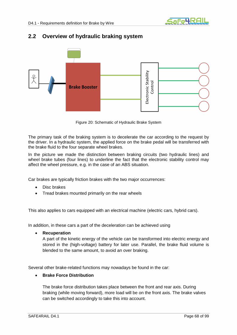
D4.1 - Requirements definition for Brake by Wire
SAFE4RAIL D4.1 Page 68 of 99
2.2 Overview of hydraulic braking system
Ele
ctro
nic
Sta
bili
ty
Co
ntr
ol
Brake Booster
Figure 20: Schematic of Hydraulic Brake System
The primary task of the braking system is to decelerate the car according to the request by the driver. In a hydraulic system, the applied force on the brake pedal will be transferred with the brake fluid to the four separate wheel brakes.
In the picture we made the distinction between braking circuits (two hydraulic lines) and wheel brake tubes (four lines) to underline the fact that the electronic stability control may affect the wheel pressure, e.g. in the case of an ABS situation.
Car brakes are typically friction brakes with the two major occurrences:
Disc brakes
Tread brakes mounted primarily on the rear wheels
This also applies to cars equipped with an electrical machine (electric cars, hybrid cars).
In addition, in these cars a part of the deceleration can be achieved using
Recuperation
A part of the kinetic energy of the vehicle can be transformed into electric energy and
stored in the (high-voltage) battery for later use. Parallel, the brake fluid volume is
blended to the same amount, to avoid an over braking.
Several other brake-related functions may nowadays be found in the car:
Brake Force Distribution
The brake force distribution takes place between the front and rear axis. During
braking (while moving forward), more load will be on the front axis. The brake valves
can be switched accordingly to take this into account.

D4.1 - Requirements definition for Brake by Wire
SAFE4RAIL D4.1 Page 69 of 99
Brake Requests from ACC or other partner functions
When an assistance function like adaptive cruise control wants to brake, the braking
has to be executed by the system, not by the driver. So there will be an interface
between the ACC Ecu and the brake ECU and a control loop in the ACC function.
Driver Assistance Functions
By that is meant braking-related functionality which assist the driver in his everyday
use of the vehicle. E.g. the autonomous hold of the vehicle on an inclination, when
the driver wants to drive off, helps to prevent the car from rolling backwards. When
using the old hand brake instead, a good multitasking is required in this situation.
Slipping Control
Slipping control takes care of slipping wheels which might occur on low- ground (icy,
snowy, sandy).
ABS
Depending on the ground as well, a heavy braking can result in blocked wheels. The
function ABS prevents this and serves two purposes: to have an optimal short
stopping distance (under the given environmental conditions of course) and second,
to still have the vehicle steerable.
Stability Control
Stability Control takes care of situations where the vehicle starts to leave the track with its front or rear part due to too high speed or slipping ground conditions. According to which situation is at hand, a specific wheel is braked by the system to give back stability to the car.
In Figure 21, the overall system is drawn in a simplified way. There are several techniques to enhance the brake force of the driver (vacuum - , hydraulic - , electric brake booster). These brake boosters have to be constructed in such a way that no error can lead to the hazard that the driver’s force is not pushed through anymore.
Decisive, in the case of an electric brake booster is also the determination of the driver request. For that the brake pedal force or the brake pedal path have to be determined. The sensors that enter here are crucial for the system.
The brake booster is usually a part or attached to the tandem main cylinder, which supplies the car with two brake circuits (law regulation). In the picture is drawn one brake circuit connected with an input valve to one wheel. That valve, the output valves and the pump serve for the traction and stability control.
Also in the picture can be seen the speed sensors of the wheels. If based on the Hall effect, they create pulses so that the control unit counts them to determine the speed of each wheel.

D4.1 - Requirements definition for Brake by Wire
SAFE4RAIL D4.1 Page 70 of 99
Figure 21: Principle of a car braking system
ECU for Vehicle Dynamics
Stability Control
Traction Control
Wheel speed
Stee
rin
g an
gle
Yaw
rat
e
Late
ral a
ccel
erat
ion
Electrical Brake Booster
Pedal force by driver
Auxiliary force by motor
Hydraulic Brake Booster
Determination of driver brake request
MC
pre
ssu
re
Co
mm
un
icat
ion
Vaccum Brake Booster
Auxiliary force

D4.1 - Requirements definition for Brake by Wire
SAFE4RAIL D4.1 Page 71 of 99
2.3 Overview of brake-by-wire systems
First of all, we should make precise what is meant by a brake-by-wire system. The definition is not clear, as there are always “wires” in the vehicle.
Brake-by-Wire can refer to
No mechanical (hydraulic) connection between the brake pedal and the wheel brakes
No hydraulic or pneumatic components at all
The last interpretation would be named a dry/full brake-by-wire system. In such a full brake-by-wire system also the fallback solution or any redundant brake system component must be built completely dry.
The first interpretation is usually understood implicitly when speaking of a brake-by-wire system.
Full brake-by-wire systems are not state of the art in the automotive domain. Partial brake-by-wire systems, however, are already used frequently, e.g within recuperation in electric/hybrid vehicles.
Table 1 shows roughly the development of the braking system in the automotive industry (service brake for passenger cars only).
System Technology
Braking System with Vacuum Brake Booster Hydraulic
Braking System with Hydraulic Brake Booster Hydraulic
Example of an Electrohydraulic Brake:
SBC (by Bosch) Brake-by-wire with mechanical fallback
Example of an Electromechanical Brake:
EWB (by Continental/ Siemens VDO)
Dry brake-by-wire system, but not in series production
Braking System with Electrical Brake Booster Hydraulic push-through, but amplification is electric (i.e. partially brake-by-wire)
Table 1: Braking system in the automotive industry
Example of an Electrohydraulic Brake: SBC (by Bosch)
In 2001 the Robert Bosch GmbH has developed an electrohydraulic brake under the name SBC (Sensotronic Brake Control), in cooperation with Mercedes.
Compare the next picture (Figure 22).
The driver deceleration request is determined by a sensor (or sensors) and the ECU computes and drives the desired hydraulic pressure on the wheels. In normal operation mode, there is no mechanical connection of the brake pedal to the wheel brakes. In the event

D4.1 - Requirements definition for Brake by Wire
SAFE4RAIL D4.1 Page 72 of 99
of a complete loss of the electric brake, the separation valves close yielding a reduced hydraulic braking (mechanical fallback to driver’s force).
Separation Valves
Main Cylinder
Front Left
Front Right
Modulator of Hydraulic Pressure
ECUSensor
Hydraulic Reservoir
Figure 22: Sensotronic Brake Control (adapted from [29])
Example of an Electromechanic Brake: EWB (by Continental/ Siemens VDO)
Continental/Siemens VDO have developed a dry brake-by-wire system, which is currently not in series production. This system is derived from the old technique (used in carriages) to drive a wedge between the wheel and the frame. Here the wedge is driven electrically to press the brake pads to the disc (see Figure 23).
Wh
eel d
isc
pad
Figure 23: Principle of a Wedge Brake (adapted from [30])
The system is very dynamic, allows precise control and with the self-enhancement effect that this wedge brake offers, the standard automotive voltage level of 12 V should be sufficient.
The lack of any hydraulic components would make a full integration as a “wheel module” possible.

D4.1 - Requirements definition for Brake by Wire
SAFE4RAIL D4.1 Page 73 of 99
The biggest challenge in developing a brake-by-wire system is certainly to ensure that the system always works: The system must be fault-tolerant and it must be ensured that the safe state of the system can be reached at any time. Loss of electric power supply has to be avoided either by the vehicle environment or by the braking control unit itself. But also other technological challenges have to be met. In a hydraulic system, the driver is exposed to a brake pedal resistance due to the anti-pressure of the fluid in the main cylinder. In a pure electrical brake, this feeling should or even must be emulated, according to the controllability of the brake pedal by the driver.
Principle of Recuperation
Recuperation is a technology in hybrid and electric vehicles to brake electrically, not hydraulically. Recuperation itself does not need hydraulic components in the car. However as such a braking is not always possible, the hydraulic part must not disappear. More precisely, during regenerative braking, a part of the kinetic energy of the vehicle will be transformed into electrically stored energy in the high voltage battery. However if the drive train is not closed or if the battery is already fully charged, recuperation is not possible. On the other side, if it is possible, it needs to be ensured, that the exact energy amount will be recuperated as requested by the driver in a corresponding hydraulic braking. If the brake fluid pressure has already raised and at the same time, regenerative braking is switched on, there is too much brake pressure in the system (overbraking). To avoid this, valves will be switched on or off to blend volume into a fluid reservoir. Switching off recuperation, this blended volume has to be pumped into the brake circle back again.
With its potential to regain the energy, thus saving petrol or electric energy, recuperation is nowadays state of the art and is partial brake-by-wire.
ECU for Recuperation
Management-Systemfor Battery/ Power
Electronics
High-Voltage Battery
AC-DC Converter
Electrical Machine
as Generator Ener
gy f
low
Drive train closed?
Determination of Driver Brake Request/
Main Cylinder Pressure/Valve switching times/...
Current Limitation of HV-Battery
Ro
tati
on
al E
ner
gy
Regenerative brake torque – desired and current value
Figure 24: Simplified principle of recuperation in a vehicle

D4.1 - Requirements definition for Brake by Wire
SAFE4RAIL D4.1 Page 74 of 99
2.4 Advantages & disadvantages of brake-by-wire
On the plus side, a brake-by-wire system could save components and installation space in the vehicle.
Due to the lack of fluid flow, dry brake-by-wire systems will have a better dynamics. Moreover for a partial (or full) brake-by-wire system, it is feasible to implement assistance functions which help to attain a faster brake response in case of a possible emergency situation. Also an adaption of brake characteristics for various driving situations is possible. During an ABS situation there won’t be any vibration of the brake pedal anymore.
On the negative side, additional safety measures have to be installed, from which it is not clear in the beginning whether the resulting system will be “smaller” than the hydraulic system. For example, an add-on energy supply or other mechanisms are needed to ensure braking during energy loss.
Moreover, for the driver’s feeling of the brake pedal a simulation of the pedal anti-force is necessary.
Furthermore, the impact of full brake-by-wire system to cost and maintenance isn’t clear right now. Regarding maintenance on one hand, brake fluid will be not necessary anymore. But on the other hand, additional electrical components and software perhaps will need same level of maintenance like “traditional” brake systems. Cost perspective will be pending on different aspects like number integrated systems, needed backup systems/redundancy, and so on.
2.5 Overview of other X-by-wire systems
Every car nowadays has a drive-by-wire system (even 20 years ago), where the driver’s acceleration request from the gas pedal is not mechanically linked anymore to the throttle position (in a petrol engine) by a Bowden cable.
Indeed, there are sensors detecting the gas pedal angle/ path. With increasing pedal values, the throttle will open more, but this time purely electronic.
Furthermore, the whole drive train is controlled: the injection of the fuel, the lightning (in a petrol engine) and the opening of the in- and output valves.
Shift-by-wire is quite standard for automatic transmission vehicles. It replaces the mechanical connection between the gear shift to the transmission by electric signals.
Steer-by-wire for passenger cars is only installed in one series production car (Infiniti Q50). It is equipped with three redundant control units and the still present steering column serves very likely as a mechanical backup.
2.6 Outlook
Following the development of the automotive industry in the last decades, it is apparent that the tendency is towards electrification. Mechanical functions were replaced over the years by electric analogues with certain benefits: controllability that is more precise, add-on functionalities, cost reduction, space reduction, and many more.
Nowadays there are already very fruitful attempts to pursue this development also in the area of braking systems. Since braking is one of the most safety-critical applications in the vehicle, the step to a full brake-by-wire system is a large on. If it proves to be as advantageous as already existing x-by-wire technologies, the way from a partial to a full brake-by-wire system will be only a matter of time.

D4.1 - Requirements definition for Brake by Wire
SAFE4RAIL D4.1 Page 75 of 99
Chapter 3 Safety
Critical systems for safe operation are systems whose failure may result in serious consequences: loss of life, significant property damage, or damage to the environment. Normative frameworks are available in many domains, including railway and automotive. These normative frameworks stipulate that the safety of a system shall be demonstrated.
This chapter presents the normative frameworks in automotive and railway domains and, driven by those standards, will provide a brief description of the safety approach to develop electronic safety-critical systems.

D4.1 - Requirements definition for Brake by Wire
SAFE4RAIL D4.1 Page 76 of 99
3.1 Overview of CENELEC Railway Standards
A brief overview of the standards used for the development of electronic equipment to be used in rolling stock is supplied in the following paragraph.
The aim of this chapter is to mention the most relevant standards related to railway electronic development and safety critical electronic development, relevant for the work in WP4. It is not claimed to provide a complete overview of all applicable standards, as this is out of the scope of this deliverable. These standards cover the whole product lifecycle and in detail the development process to be applied and demonstrated to get final conformance.
For a wider list of applicable standard for railway braking systems please refer to Chapter 1 and for standards applicable to railway electronic product please refer to §4.1.
The main CENELEC standards applicable to railway system and their relationship are shown in Figure 25.
Figure 25: Main CENELEC railway application standards
EN50126:1999 ([3]) – Defines processes and describes methods to be used to specify and demonstrate reliability, availability, maintainability and safety (RAMS).
EN50128:2011 ([25]) – Specifies procedures and technical requirements for the development of software for programmable electronic systems for use in railway control and protection applications; defines all the actions to be taken in order to demonstrate the safety of the software.
EN50129:2003 ([26]) – Defines the conditions that shall be satisfied in order that a safety-related electronic railway system can be accepted as adequately safe for its intended
Complete Railway System
Complete Railway Signalling System
Individual Sub-System
Individual Item of Equipment
EN 50128
(Software)
EN 50129
(System Safety)
EN 50126
(RAMS)
EN 50159
(Communication)

D4.1 - Requirements definition for Brake by Wire
SAFE4RAIL D4.1 Page 77 of 99
application. Specifies procedures and information for identifying the credible failure modes of hardware components.
EN50159:2010 ([27]) – Specifies the communication related requirements for evidence of functional and technical safety; the standard is applicable to safety-related electronic systems using a transmission system for digital communication purposes, which was not necessarily designed for safety-related applications.
Standard EN 50129 is normally limited to the signalling subsystem. However its application to on board control systems (or in general to the whole of the railway system) is becoming the state-of-the-art.
At the time of writing of this document, two provisional standards, prEN50126 and prEN50129, are issued for comments. Regarding rolling stock, also prEN50657 (“RAILWAY APPLICATIONS - ROLLING STOCK APPLICATIONS - SOFTWARE ON BOARD OF ROLLING STOCK, EXCLUDING RAILWAY CONTROL AND PROTECTION APPLICATIONS”) and prEN50155 are in progress. The standards will most probably be ratified during the S4R project; implications will have to be taken into account.
Also IEC 61508 – Functional safety of electrical/electronic/programmable electronic safety-related systems has to be quoted as:
often used as reference and certification standard for safety related electronics in railway systems and
the first reference for sector specific functional safety related standards (industrial, railway, automotive, etc…).
CENELEC standards are replayed on the international scene by the IEC standards according to the following table:
CENELEC IEC
50126:1999 62278:2002
50129:2003 64425:2007
50128:2001 62279:2002
50128:2011 62279:2015
50159:2010 62280:2002
Table 2: CENELEC and IEC standards relationship
The triple of standards 50126/8/9 covers lifecycle for railway safety critical applications.
The development V-process is used from system specification (EN 50126) down to hardware (EN 50129) and software (EN 50128) development and back, up to system validation and final assessment. The development of safe communications is ruled by EN 50159.

D4.1 - Requirements definition for Brake by Wire
SAFE4RAIL D4.1 Page 78 of 99
Safety is a non-separable part of Reliability, Availability, Maintainability, Safety requirements sets. RAMS management is addressed by EN 50126 and it’s a top-down process with allocation of system requirements to subsystems and down to hardware and software parts.
Risk analysis is applied on the whole process to assure risk definition and risk reduction through the definition of the:
safety critical functions
safety critical requirements
safety integrity levels (SIL 1 to 4)
side by side with functional requirements.
FSM (Functional Safety Management, a.k.a. QSM “Quality and Safety Management”) is applied starting with a Functional Safety Plan along the whole lifecycle. FSM has to assure that correct processes to assure safety has been established, planned and will be controlled.
Verification & Validations activities (V&V) have to be applied to any development phase and step to assure, with a “four eyes” check approach, the correct and complete execution for safety requirements.
Certification can cover generic product, generic application or specific application.
The safety case issued for assessment and certification has to cover documented evidence for functional and technical safety, quality management and safety management.
EN 50129 deals with the railway safety critical system life cycle, the “hardware” one since software development is left to EN 50128. The standard includes a definition for the Safety Integrity Levels with four SIL levels (SIL1 to SIL4) according to:
quantitative requirements: four different levels of allowed failure rates (per hour and per function)
qualitative requirements to address systematic faults
fault tolerance behaviour
Fulfilment of safety has to be assured via:
Systematic safety (development correctness via demonstrated respect of specified development processes)
Stochastic safety (fault behaviour demonstrated and calculated)
Use of safety architectures to get safety requirements and targets, mainly:
Composite fail safety (redundant safety parts, at least doubled, multiple hardware or
multiple design to manage 1 fault on n different parts performing the same function,
common mode/cause faults among redundant parts must be avoided)
Re-active fail safety (diagnostic solutions, find fault and react negating it right time
and speed, main function and diagnostic function have to be independent as to avoid
common cause hazardous faults)
Inherent fail-safety (all credible faults are not hazardous)
FMECA and FTA are two recommended techniques to calculate quantitative safety figures (PFH).
Electronic components fault models and reliability models to be selected among different possible references (e.g. IEC TR 62380, Siemens SN 29500, Telcordia SR-332, MIL-HDBK-217, etc…).

D4.1 - Requirements definition for Brake by Wire
SAFE4RAIL D4.1 Page 79 of 99
EN50129 doesn’t cover programmable logic components explicitly, as a consequence prescriptions coming from IEC 61508 are often recalled for this technology (CLC/TR50506-2 is also a railway-specific reference).
EN 50128 deals with software. A lifecycle approach is used from requirements to maintenance phases.
Systematic safety assurance is applied, with strong control for development processes, organizational structure and roles and responsibilities.
Integrity SIL0 to SIL4 is qualitatively defined (non-safety related, low, medium, high, very high) and the development process is specified according to the SIL level.
Process:
V model applied
phases defined with requirements for each one to be applied:
requirements
architecture
design & implementation
components design
components implementation and testing
verification and testing
integration
validation
maintenance
development techniques and measures to applied with applicability defined from
mandatory to not recommended (M, HR,R,_, NR) for SIL level
fully defined and safety justified development tools chain
EN 50159 deals with the requirements for safety related communications and the safety layer developed to cover them. Information has to be exchanged assuring:
Authenticity
Integrity
Timeliness
Sequence
The design of the communication safety layer has to take care of:
Effects of non-trusted hardware faults
Minimum list of faults to be considered
Probability that a correct safety code can be generated by non trusted transmission system
Error on transmission media
Get the safety target (hazardous failure rate) coming from the system safety analysis and defined for the transmission system

D4.1 - Requirements definition for Brake by Wire
SAFE4RAIL D4.1 Page 80 of 99
Operation within different categories (from Cat1 - “closed” and with unauthorized access assumed to be incredible - to Cat3 - “Open” and with threats of unauthorized access)
Independence between transmission and safety layers
Threats to be managed are repetition, deletion, insertion, re-sequence, corruption, delay and masquerade.
For the defences against the threats, the following parameters have to be specified: sequence number, time stamp, time-out, source and destination identification, feedback messages, identification procedure, safety code, cryptographic techniques and key management.

D4.1 - Requirements definition for Brake by Wire
SAFE4RAIL D4.1 Page 81 of 99
3.2 Automotive
The rising of more and more complicated electric and electronic systems that took over and still is taking over mechanical functionalities in the vehicle made it necessary to introduce an automotive standard that addresses the safety of such systems. This standard is the ISO 26262 ([31]), which applies in its current version (1st edition from 15th Nov. 2011) to series production passenger cars up to a maximum weight of 3500 kg.
ISO 26262 “Road vehicles – Functional safety” does provide guideline to ensure safety of the function with respect to electrical/electronic and programmable malfunctions only. Based on usage of the V-Model, different processes/activities has to be addressed/conducted while going through the development phases.
Functional safety in the context of ISO 26262 is by definition the absence of unreasonable risk due to hazards caused by malfunctions of electric/electronic systems. Hence, the ISO 26262 does not apply to mechanical malfunctions.
The approach of the ISO26262 to handle safety critical systems is along the lines of the classical V-model stemming from software development (see image). The upper left of the “V” is given by the concept phase (§3 of ISO) and one half of the paragraph on system development (§4 – specifically technical safety requirements, system design). The upper right of the “V” is given by the other half of the paragraph on system development (§4 – specifically validation) and the production/operation paragraph (§7). The lower part of the V-model is comprised of the software and hardware paragraphs (§5,6), which addresses hardware design, evaluation of the hardware metrics and testing and on the other hand, software design, unit design, testing, verification.
Figure 26 ISO 26262 V-Model ([31])

D4.1 - Requirements definition for Brake by Wire
SAFE4RAIL D4.1 Page 82 of 99
How is the ISO 26262 applied now in a concrete situation? The starting point should be the definition of a scope of view, the so called item definition. By definition, the item is the system to implement a function at the vehicle level. In the item definition, the function/ functionality under investigation has to be given together with its interfaces to out-of-scope elements, possible restrictions on the use of the function, environmental conditions or known hazards. E.g. on the vehicle level, if one considers the function “brake-by-wire”, for sure the corresponding electronic control unit and brake sensors are part of the item, whereas the electronic stability control interferes but probably won’t be part of the item. Now the next process step according to ISO 26262 would be to set up a hazard analysis and risk assessment (HARA) of the item on vehicle level. This analysis is used to determine the safety goals for the item such that unreasonable risk is avoided. To that aim the method of ASIL determination is used. To determine an ASIL (automotive safety integrity level) of a hazard, three impact factors have to be considered: Controllability-Severity-Exposure (C-S-E). The following tables show roughly the values assigned to these impact factors.
Controllability C0 C1 C2 C3
Description Controllable in
general Simply
controllable Normally
controllable
Difficult to control or
uncontrollable
Table 3: Controllability of vehicle in a specific situation by driver (in context of HARA)
Severity S0 S1 S2 S3
Description No injuries
Light and moderate
injuries
Severe and life-threatening
injuries (survival probable)
Life-threatening injuries (survival uncertain), fatal
injuries
Table 4: Severity of potential harm due to accident with focus on driver and environment (in context of HARA)
Exposure E0 E1 E2 E3 E4
Description Incredible Very low
probability Low
probability Medium
probability High
probability
Table 5: Exposure of a specific situation for defined timeframe (in context of HARA)

D4.1 - Requirements definition for Brake by Wire
SAFE4RAIL D4.1 Page 83 of 99
For every hazardous event of the item (malfunction), the ASIL is determined according to Table 6
Severity
Exposure Controllability
C1 C2 C3
S1 E1 QM QM QM
E2 QM QM QM
E2 QM QM A
E4 QM A B
S2 E1 QM QM QM
E2 QM QM A
E3 QM A B
E4 A B C
S3 E1 QM QM A
E2 QM A B
E3 A B C
E4 B C D
Table 6: ASIL Determination ([31])
Here QM has no safety relevance, but the resulting requirements have to be treated with general quality management measures.
How would the safety goals look like for the item “braking system”?
In the above mentioned VDA360 paper, safety goals regarding the automotive braking system are listed. It should be understood however, that these safety goals are neither determined nor set as a standard. Therefore for a concrete project they might differ.
Here we list the safety goals:
Avoid too low brake torque during driving (max. ASIL D)
Avoid unintended or too high brake torque during driving (max. ASIL D)
Avoid no activation of brake lights (max. ASIL B)
The “max.” in the above ASIL levels depends on the specific functionality. E.g. if a driver assistance function like ACC is braking, the hazard ‘too low brake torque’ won’t be safety relevant at all, as the driver must be in the loop and is responsible. (This depends on

D4.1 - Requirements definition for Brake by Wire
SAFE4RAIL D4.1 Page 84 of 99
controllability, so has to be evaluated in each single case.) The fault tolerance time and the fault amplitude depend as well on the specific functionality.
According to the ISO 26262 process, after the HARA has been done, the functional and technical safety concepts have to be developed. The functional safety concept abstracts from the specific system, while the technical safety concept uses the (initial) system architecture given by the car manufacturer resp. the component architecture (HW/SW) of the OEM supplier. E.g. the functional safety concept would define a requirement as “if brake pressure <= xxx bar and (…), then switch on pump” and a related broken-down requirement in the technical safety concept could read as “if sensor S2 detects a pressure <=xxx bar and (…), then drive the output current I = xxx A on pin out21 of the ECU“. These requirements look very much like coming from the nominal function. Indeed sometimes it is not easy to distinguish a nominal from a safety requirement except through the attributed ASIL.
The safety concept must contain requirements concerning the detection of faults of the item, the mitigation of failures and the transition to the safe state. The following picture, taken from ISO 26262 shows that the safety concept has to provide requirements which can be traced back to the safety goals, determined from the hazard analysis and risk assessment. This traceability is a key request of the ISO26262 process and does include the testing topic as well.
Figure 27: Generic approach of safety requirement allocation ([31])
The safety requirements, which are in the end requirements on software and on hardware, have to be implemented and tested according to ISO 26262, parts 4, 5 and 6. For distribution of safety requirements to different subsystems/components/etc., decomposition can be applied. ASIL decomposition is allowed whenever the decomposition partners are independent and fulfill the safety goal on their own. The verification of the requirements changes our current position in the V-model from left to right.
Finally, according to ISO 26262, part 4-9, a safety validation is necessary. Validation must be executed in a representative vehicle, when the item under consideration is integrated. Validation must give evidence if the safety goals are sufficient and (if yes) if they have been finally achieved on the vehicle level. Having done all this, the safety case has to be written, which gives arguments that the item under consideration is free of unreasonable risks.
Finally it should be mentioned, that for projects which are not complete new developments, but more or less carry-over, ISO 26262 allows a Delta-process, making use of an impact analysis of the Delta changes on the item under consideration.

D4.1 - Requirements definition for Brake by Wire
SAFE4RAIL D4.1 Page 85 of 99
Chapter 4 Legislations & Standards
4.1 Railway
In the following sub-clauses a short presentation (not exhaustive) of the regulations, directives and standards applicable to electronic devices intended for railway application (rolling stock and on-board equipment).
As depicted in the figure below, there are two main groups of documents:
Mandatory documents (see §4.1.1), furthermore divided in:
o Interoperability Directive
o Mandatory rules
o Mandatory standards (directly quoted in rules)
Voluntary documents (see §4.1.2), furthermore divided in:
o Harmonized standards (EN)
o Other standards and documents (IEC, TR, ...)
o Company standards
Figure 28: Hierarchy of the applicable documents for railway application

D4.1 - Requirements definition for Brake by Wire
SAFE4RAIL D4.1 Page 86 of 99
4.1.1 Mandatory documents
The directive of the European Parliament and of the Council no 2016/797/EU represents the applicable legislation in Europe for rail system. The interoperability directive 2016/797/EU is the recast of the previous interoperability directive 2008/57/EC plus the subsequent amending directives (2014/106/EU, 2014/38/EU, 2013/9/EU, 2014/897/EU, 2011/18/EU, 2009/131/EC).
In addition the mandatory rule 1302/2014 (already mentioned as reference in chapter §1.1.1) quotes standards that shall be applied for electronic board to be installed on a rolling stock. (see Annex J of 1302/2014).
Code Title Abstract
2016/797/EU DIRECTIVE of the European Parliament and of the Council of 11 May 2016 on the interoperability of the rail system within the European Union.
This Directive establishes the conditions to be met to achieve interoperability within the Union rail system in a manner compatible with Directive (EU) 2016/798 in order to define an optimal level of technical harmonization, to make it possible to facilitate, improve and develop rail transport services within the Union and with third countries and to contribute to the completion of the single European railway area and the progressive achievement of the internal market. Those conditions concern the design, construction, placing in service, upgrading, renewal, operation and maintenance of the parts of that system as well as the professional qualifications of, and health and safety conditions applying to, the staff who contribute to its operation and maintenance
2008/57/EC Directive on the interoperability of the rail system within the Community (repealing Directives 96/48/EC and 2001/16/EC from 19 July 2010).
This Directive sets out to establish the conditions to be met to achieve interoperability within the Community rail system in a manner compatible with the provisions of Directive 2004/49/EC. These conditions concern the design, construction, placing in service, upgrading, renewal, operation and maintenance of the parts of this system as well as the professional qualifications and health and safety conditions of the staff who contribute to its operation and maintenance
2014/106/EU Directive of 5 December 2014 amending Annexes V and VI to Directive 2008/57/EC of the European Parliament and of the Council on the interoperability of the rail system within the Community
Partial amendment of directive 2008/57/EC
2014/38/EU Directive of of 11 March 2014 amending Annex III to Directive 2008/57/EC of the European Parliament and of the Council as far as noise pollution is concerned
Partial amendment of directive 2008/57/EC

D4.1 - Requirements definition for Brake by Wire
SAFE4RAIL D4.1 Page 87 of 99
Code Title Abstract
2013/9/EU Directive of of 11 March 2013 amending Annex III to Directive 2008/57/EC of the European Parliament and of the Council on the interoperability of the rail system within the Community
Partial amendment of directive 2008/57/EC
2014/897/EU Commission Recommendation [59] of 5 December 2014 on matters related to the placing in service and use of structural subsystems and vehicles under Directives 2008/57/EC and 2004/49/EC of the European Parliament and of the Council (DV29bis), repealing Commission Recommendation 2011/217/EU
2011/18/EU Directive of 1 March 2011 amending Annexes II, V and VI to Directive 2008/57/EC of the European Parliament and of the Council on the interoperability of the rail system within the Community
Partial amendment of directive 2008/57/EC
2009/131/EC Directive of 16 October 2009 amending Annex VII to Directive 2008/57/EC of the European Parliament and of the Council on the interoperability of the rail system within the Community
Partial amendment of directive 2008/57/EC
Table 7: Directives on the interoperability of the rail system
Code Title Abstract
1302/2014/EU Commission Regulation concerning a technical specification for interoperability relating to the ‘rolling stock - locomotives and passenger rolling stock’ subsystem of the rail system in the European Union
Specifications by which each subsystem or part of subsystem is covered in order to meet the essential requirements and to ensure the interoperability of the European Community's high speed and conventional rail systems.
Table 8: Mandatory rules on the interoperability of the rail system

D4.1 - Requirements definition for Brake by Wire
SAFE4RAIL D4.1 Page 88 of 99
Code Title Abstract
EN 50125-1: 2014
Railway applications. Environmental conditions for equipment. Rolling stock and on-board equipment
Intends to define environmental conditions within Europe. The scope of this European Standard covers the definitions and ranges of the following parameters: Altitude, temperature, humidity, air movement, rain, snow and hail, ice, solar radiation, lightning, pollution for rolling stock and on-board equipment (mechanical, electromechanical, electrical, electronic).
EN 50153: 2014
Protective provisions relating to electrical hazards
Defines requirements to be applied in the design and manufacture of electrical installations and equipment to be used on rolling stock to protect persons from electric shocks. This European Standard is applicable to rolling stock of rail transport systems, road transport systems, if they are powered by an external supply (e.g. trolley buses), magnetically levitated transport systems and to the electrical equipment installed in these systems.
EN 45545-2:2013 +A1:2015
Railway applications – Fire protection of railway vehicles – Part 2: Requirements for fire behaviour of materials and components
Specifies the reaction to fire performance requirements for materials and products. The operation and design categories defined in EN 45545-1 are used to establish hazard levels that are used as the basis of a classification system. For each hazard level, this part specifies the test methods, test conditions and reaction to fire performance requirements
Table 9: Mandatory standards quoted in regulation

D4.1 - Requirements definition for Brake by Wire
SAFE4RAIL D4.1 Page 89 of 99
4.1.2 Voluntary documents (EN standards)
The last publication of the European Commission regarding the titles and references of harmonised standards under Union harmonisation legislation dates 8 July 2016:
2016/C 249/04 Commission communication in the framework of the implementation of the Directive 2008/57/EC of the European Parliament and of the Council on the interoperability of the rail system within the Community
This is a list of harmonized standards that if applied, give presumption of conformity with the Interoperability Directive.
This list includes standard like the EN 50155, that is the reference for the development and test of electronic equipment used on rolling stock, as well as all the standard related to safety (EN 5012x and EN 50159 described in detail in §3.1).
Furthermore the list includes other standards that address specific design aspects like insulation distances, supply voltages, materials to be used, etc…
Code Title Abstract / Scope
EN 50155: 2007 + AC: 2010 + AC: 2012
Railway applications - Electronic equipment used on rolling stock
This standard applies to all electronic equipment for control, regulation, protection, supply, etc…, installed on rail vehicles ….
This standard covers the conditions of operation, design, construction, and testing of electronic equipment, as well as basic hardware and software requirements considered necessary for competent, reliable equipment.
For the purpose of this standard, electronic equipment is defined as equipment mainly composed of semiconductor devices and recognized associated components. These components will mainly be mounted on printed boards.
EN 50126-1: 1999 + AC: 2006 + AC: 2010 + AC: 2012
Railway applications - The specification and demonstration of Reliability, Availability, Maintainability and Safety (RAMS) - Part 1: Basic requirements and generic process
Detailed explanation in §3.1
EN 50129: 2003 + AC: 2010
Railway applications - Communication, signalling and processing systems - Safety related electronic systems for signalling
Detailed explanation in §3.1
EN 50159: 2010
Railway applications - Communication, signalling and processing systems – Safety related communication in transmission systems
Detailed explanation in §3.1

D4.1 - Requirements definition for Brake by Wire
SAFE4RAIL D4.1 Page 90 of 99
Code Title Abstract / Scope
EN 50124-1:2001 + A1:2003 + A2:2005 + AC:2007 + AC:2010
Railway applications‐Insulation coordination. Part 1: Basic requirements Clearances and creepage distances for all electrical and electronic equipment
Deals with insulation coordination in railways. It applies to equipment for use in signalling, rolling stock and fixed installations up to 2000 m above sea level. Insulation coordination is concerned with the selection, dimensioning and correlation of insulation both within and between items of equipment. In dimensioning insulation, electrical stresses and environmental conditions are taken into account.
EN 45545-1:2013
Railway applications – Fire protection of railway vehicles – Part 1: General
Deals with measures and requirements intended to protect passengers and staff in railway vehicles in the event of a fire on board. EN 45545 specifies:
- fire protection measures for railway vehicles;
- verification methods for these measures.
EN 45545-2:2013 +A1:2015
Railway applications – Fire protection of railway vehicles – Part 2: Requirements for fire behaviour of materials and components
Specifies the reaction to fire performance requirements for materials and products. The operation and design categories defined in EN 45545-1 are used to establish hazard levels that are used as the basis of a classification system. For each hazard level, this part specifies the test methods, test conditions and reaction to fire performance requirements
EN 45545-5:2013 + A1:2015
Railway applications - Fire protection on railway vehicles - Part 5: Fire safety requirements for electrical equipment including that of trolley buses, track guided buses and magnetic levitation vehicles
Specifies the fire safety requirements for electrical equipment on railway vehicles, including that of trolley buses, track guided buses and magnetic levitation vehicles.
EN 50125-1: 2014
Railway applications. Environmental conditions for equipment. Rolling stock and on-board equipment
Intends to define environmental conditions within Europe. The scope of this European Standard covers the definitions and ranges of the following parameters: Altitude, temperature, humidity, air movement, rain, snow and hail, ice, solar radiation, lightning, pollution for rolling stock and on-board equipment (mechanical, electromechanical, electrical, electronic).
EN 60529: 1991 + Corr: 1993 + A1: 2000 + A2: 2013
Classification of protection degrees provided by envelopes
Applies to the classification of degrees of protection provided by enclosures for electrical equipment with a rated voltage not exceeding 72,5 kV
EN 50163: 2004 +A1:2007 + AC:2010 + AC:2013
Railway applications – supply voltages of traction systems
Specifies the main characteristics of the supply voltages of traction systems, such as traction fixed installations, including auxiliary devices fed by the contact line, and rolling stock, for use in the following applications
Table 10: Presumption of conformity - Harmonized standards

D4.1 - Requirements definition for Brake by Wire
SAFE4RAIL D4.1 Page 91 of 99
4.1.3 Other standards
Below is provided a description of the standards, not included in the list 2016/C 249/04, usually used for the development of an electronic board to be installed on a rolling stock.
The standards are used as reference for reliability aspects and specifies test and acceptance criteria related to the environment (electromagnetic compatibility, shock and vibration, climatic).
Code Title Abstract / Scope
EN 60812: 2006
Analysis techniques for system reliability. Procedure for failure mode and effects analysis (FMEA)
This Standard describes Failure Mode and Effects Analysis (FMEA) and Failure Mode, Effects and Criticality Analysis (FMECA), and gives guidance as to how they may be applied to achieve various objectives by: providing the procedural steps necessary to perform analysis; identifying appropriate terms; defining basic principles; providing examples of the necessary worksheets or other tabular forms
IEC TR 62380: 2004
Reliability data handbook – Universal model for reliability prediction of electronics components, PCBs and equipment
Provides elements to calculate the failure rate of mounted electronic components. It makes equipment reliability optimization studies easier to carry out, thanks to the introduction of influence factors
Table 11: Other standards – Reliability
Code Title Abstract / Scope
EN 50121-1: 2017
Railways applications – EMC Electromagnetic compatibility
This European standard outlines the structure and the content of the whole set. It specifies the performance criteria applicable to the whole standards series. Clause 5 provides information about the EMC management. This part alone is not sufficient to give presumption of conformity to the essential requirements of the EMC-Directive and is intended to be used in conjunction with other parts of this standard.
EN 50121-3-2: 2015
Railway applications ‐ Electromagnetic
compatibility. Part 3‐2: Rolling stock –Apparatus
This European Standard applies to emission and immunity aspects of EMC for electrical and electronic apparatus intended for use on railway rolling stock. EN 50121-3-2 applies for the integration of apparatus on rolling stock. The application of tests shall depend on the particular apparatus, its configuration, its ports, its technology and its operating conditions.
The objective of this standard is to define limits and test methods for electromagnetic emissions and immunity test requirements in relation to conducted and radiated disturbances. These limits and tests represent essential electromagnetic compatibility requirements.

D4.1 - Requirements definition for Brake by Wire
SAFE4RAIL D4.1 Page 92 of 99
Code Title Abstract / Scope
EN 61000-4-x Electromagnetic compatibility (EMC). Part 4-x: Testing and measurement techniques -
Relates to the immunity requirements and test methods for electrical and electronic equipment
EN 61000-6-4: 2007 + A1: 2011 + A2: 2016
Electromagnetic compatibility (EMC) - Part 6-4: Generic standards - Emission standard for industrial environments
This part of IEC 61000 for EMC emission requirements applies to electrical and electronic apparatus intended for use in industrial environments
EN 61373: 2010
Railway applications ‐ Rolling stock equipment ‐ Shock and vibration tests
Specifies the requirements for testing items of equipment intended for use on railway vehicles which are subsequently subjected to vibrations and shock owing to the nature of railway operational environment. To gain assurance that the quality of the equipment is acceptable, it has to withstand tests of reasonable duration that simulate the service conditions seen throughout its expected life
EN 60068-2-x Environmental testing - Part 2-x: Test methods
Series of standards that deals with climatic and vibration conditions. The object of the test is limited to the determination of the ability of components, equipment or other articles to be used, transported or stored at defined levels of temperature, humidity or to withstand specific vibrations and shocks
Table 12: Other standards – Environmental

D4.1 - Requirements definition for Brake by Wire
SAFE4RAIL D4.1 Page 93 of 99
4.2 Automotive
In 1958, the “World Forum for Harmonization of Vehicle Regulations” (WP 29) being part of the United Nations Economic Commission for Europe (UNECE) created a system of vehicle regulations whose focus was laid to achieve a unified framework on road safety, protection of the environment and economic trade issues. The regulations are available at [28]. Corresponding translations in one’s national language may be looked for on the national ministry’s homepages or elsewhere. The UNECE regulation (in force) legally binds all contracting parties. However this does not mean that a contracting party must recognize a type approval giving by another party as is.
For passenger cars in Germany and Italy, the ECE regulation no. 13-H is valid. Note here, that although the United States are a UNECE member, they did not sign the WP29 1958 Amendment, thus the ECE 13-H has no validity in the US car market. Other regulations apply here. In what follows we address key points of the ECE 13-H which are of importance to a brake-by-wire system.
ECE 13-H in general distinguishes between ‘service braking system’, ‘secondary braking system’ and ‘parking braking system’. The term ‘parking braking system’ should be clear.
In order to explain the role of the secondary braking system in relation with electrically controlled brakes, we cite from ECE 13-H, §5.2.20 “Special additional requirements for service braking systems with electric control transmission”, especially §5.2.20.5:
“When the battery voltage falls below a value nominated by the manufacturer at which the prescribed service braking performance can no longer be guaranteed […], the red warning signal […] shall be activated. After the warning signal has been activated, it shall be possible to apply the service braking control and obtain at least the secondary performance prescribed in paragraph 2.2. of Annex 3 to this Regulation. It should be understood that sufficient energy is available in the energy transmission of the service braking system.”
In Annex 3 (“Braking tests and performance of braking systems”), under the number 2.2.2, the secondary braking system is required to provide an average deceleration of at least 2,44 m/s^2. Similar regulations apply to other electric failures (c.f. 5.2.20.3)
Note that cars nowadays usually implement the secondary braking system by a mechanical push-through of the brake pedal to the brake main cylinders. The introduction of a brake-by-wire system within the legal regulations of ECE 13-H make it therefore necessary for the OEM to first, define the term ‘secondary braking system’ in this new context and second, to develop an appropriate technical solution to provide a safe fall-back mechanism from the ‘service braking system’ in the case of low battery voltage or other E/E-faults in the braking system.
Besides the homologation – focused ECE regulations there are other important standards in the automotive area. The most general one is certainly the AUTOSAR standard which covers numerous topics in the software development of distributed applications.
Most others depend on the area of application. Quite recently, in the context of the system development of an electric brake booster, the VDA (German association of the Automotive industry) started setting up a new paper [VDA360], which however has to be understand as a recommendation only.

D4.1 - Requirements definition for Brake by Wire
SAFE4RAIL D4.1 Page 94 of 99
Since ISO 26262 is released as an important standard for automotive industry with respect to E/E and software malfunctions, ISO 26262 has to be considered for safety-oriented development. ISO 26262 got derived from IEC 61508. More details delivered by chapter below.

D4.1 - Requirements definition for Brake by Wire
SAFE4RAIL D4.1 Page 95 of 99
Chapter 5 Summary and conclusion
The document has provided a knowledge base of the railway braking system focusing on the basic functional and safety requirements that a novel architecture will have to still fulfil according to available Standards.
A first level of partition taking care of:
main braking functionalities Emergency Service Parking
test and control functionalities
key architectural issue: redundancy and distribution energy supply and energy storage command control and transmission physical actuation
other braking related functionalities like interworking with the main one: WSP passenger alarm rescue behavior in case of fire
has been defined and will help in focusing the following WP4 activities on electronic control and transmission.
Applicable Standards for braking systems and for the development of safety electronic controls and communication have been already recalled.
The main limits identified in the current architectures are not only related to complexity and cost of the solutions that still rely on pneumatic or electro-pneumatic components, but also to the reduced, or absent, capability to manage, during emergency brake, functionalities like continuous blending between friction and dynamic brake or continuous regulation of the brake force vs speed.
How to overcome these limits? The paper suggests, at a very first level, some improvements ranging from an evolution of the current most implemented solution (EP direct brake), thus based on the principle of distributed control, to a centralization of the control logic that implies the development of new actuators and sensors devices hosted by the communication infrastructure.
The document doesn’t take into account possible innovations that would imply the development of new force generation systems since the objective of the study is more related to the integration with the new TCMS.
In the automotive domain appears relevant that the so called full (or dry) brake-by-wire system is not the SOTA while integration of several brake-related functions is nowadays common in a car.
This document will be used in the following WP4 activities (D4.2, brake-by-wire requirements specification) as knowledge reference for the present braking system architecture, the applicable Standards, the Safety requirements applicable and a first level idea of possible future innovation.

D4.1 - Requirements definition for Brake by Wire
SAFE4RAIL D4.1 Page 96 of 99
Chapter 6 List of Abbreviations
ACC Adaptive Cruise Control
BCU Brake Control Unit
CAN Controller Area Network
DMU Diesel Multiple Unit
ECU Electronic Control Unit
ED Electro-Dynamic
EMU Electrical Multiple Unit
EP Electro-Pneumatic
ERMS European Rail Traffic Management System
FMECA Failure Mode, Effects, and Criticality Analysis
FSM Functional Safety Management
FTA Fault Tree Analysis
HARA Hazard Analysis and Risk Analysis
HIL Hardware In the Loop
LCC Life Cycle Cost
LRU Last Replaceable Unit
MTB Magnetic Track Brakes
PWM Pulse Width Modulation
RAMS Reliability, Availability, Maintainability, Safety
SCMT Sistema Controllo Marcia Treno
SIL Safety Integrity Level
TCMS Train Control and Management System
TSI Technical specifications for interoperability
UIC Union Internationale des Chemins de fer (or International Union of Railways)
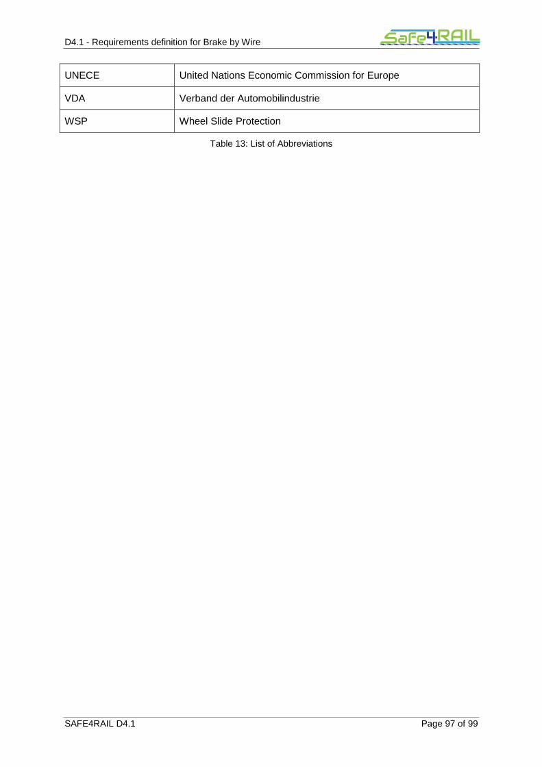
D4.1 - Requirements definition for Brake by Wire
SAFE4RAIL D4.1 Page 97 of 99
UNECE United Nations Economic Commission for Europe
VDA Verband der Automobilindustrie
WSP Wheel Slide Protection
Table 13: List of Abbreviations

D4.1 - Requirements definition for Brake by Wire
SAFE4RAIL D4.1 Page 98 of 99
Chapter 7 Bibliography
[1] 1302/2014/CE - COMMISSION REGULATION (EU) No 1302/2014 of 18 November 2014 concerning a technical specification for interoperability relating to the ‘rolling stock - locomotives and passenger rolling stock’ subsystem of the rail system in the European Union.
[2] 402/2013 - Commission Implementing Regulation (EU) No 402/2013 of 30 April 2013 on the common safety method for risk evaluation and assessment and repealing Regulation (EC) No 352/2009 Text with EEA relevance.
[3] EN 50126:1999 - Railway Applications - The Specification and Demonstration of Reliability, Availability, Maintainability and Safety (RAMS).
[4] EN 14478:2005 - Railway application – Braking - Generic vocabulary.
[5] EN 16185-1:2014 - Railway application - Braking system of multiple unit trains - Part 1: Requirements and definitions.
[6] EN 15734-1:2010 - Railway application – Braking systems of high speed trains - Part 1: Requirements and definitions.
[7] EN 14198:2004 - Railway application – Braking – Requirements for the brake system of trains hauled by a locomotive.
[8] EN 15179:2007 - Railway application – Braking – Requirements for the brake system of coaches.
[9] EN 13452-1:2003 - Railway application – Braking - Mass transit brake systems - Part 1: Performance requirements.
[10] EN 14531-1:2015 - Railway applications - Methods for calculation of stopping and slowing distances and immobilization braking - Part 1: General algorithms utilizing mean value calculation for train sets or single vehicles.
[11] EN 14531-2:2015 - Railway applications - Methods for calculation of stopping and slowing distances and immobilization braking - Part 2: Step by step calculations for train sets or single vehicles.
[12] UIC544-1 Ed. 6 (2014) - Brakes - Brake performance.
[13] EN 15595:2009+A1:2001 - Railway applications – Braking – Wheel slide protection.
[14] EN 16334:2014 - Railway applications - Passenger Alarm System - System requirements.
[15] EN 45545-1:2013 - Railway applications - Fire protection on railway vehicles - Part 1: General.
[16] EN 45545-2:2013+A1:2016 - Railway applications - Fire protection on railway vehicles - Part 2: Requirements for fire behaviour of materials and components.
[17] EN 50553:2012 - Railway applications - Requirements for running capability in case of fire on board of rolling stock.
[18] UIC 541-03 Ed. 1 (1984) – Brakes – Regulations Concerning Manufacture Of The Different Brake Parts – Driver's Brake Valve.
[19] UIC 541-5 Ed. 4 (2005) – Brakes – Electropneumatic Brake (ep Brake) – Electropneumatic Emergency Brake Override (ebo)

D4.1 - Requirements definition for Brake by Wire
SAFE4RAIL D4.1 Page 99 of 99
[20] EN 15355:2008+A1:2010 - Railway applications - Braking - Distributor valves and distributor-isolating devices.
[21] EN 15611:2008+A1:2010 - Railway applications - Braking - Relay valves.
[22] EN 16207: 2014- Railway applications – Braking - Functional and performance criteria of Magnetic Track Brake systems for use in railway rolling stock
[23] EN 15220-1:2008+A1:2010 - Railway applications - Brake indicators - Part 1: Pneumatically operated brake indicators.
[24] EN 15273-2:2013, Railway applications - Gauges - Part 2: Rolling stock gauge.
[25] EN 50128:2011 - Railway applications - Communication, signalling and processing systems - Software for railway control and protection systems.
[26] EN 50129:2003 - Railway applications - Communication, signalling and processing systems - Safety related electronic systems for signalling.
[27] EN 50159:2010 - Railway applications - Communication, signalling and processing systems - Safety-related communication in transmission systems.
[28] http://www.unece.org/trans/main/wp29/wp29regs.html
[29] Konrad Reif: Bremsen- und Bremsregelsysteme. Springer Vieweg 2010.
[30] Bernd Gombert: X-by-wire im Automobil: Von der Electronic Wedge Brake zum eCorner. Aachener Kolloquium Fahrzeug-und Motorentechnik 2007
[31] ISO 26262 („Road vehicles – Functional safety“), November 2011