d3.4 system interconnect design and sdn control · h2020 ict-04-2015 disaggregated recursive...
TRANSCRIPT
H2020 ICT-04-2015
Disaggregated Recursive Datacentre-in-a-Box
Grant Number 687632
D3.4 – System Interconnect Design and SDN Control
WP3: Optical Network and Memory hardware design and development

D3.4 – System interconnect design and SDN control
2
Due date: PM18
Submission date: 11/07/2017
Project start date: 01/01/2016
Project duration: 36 months
Deliverable lead organization
UTH
Version: 1.0
Status Final
Author(s):
George Zervas (UCL) Dimitris Syrivelis (IBM) Ilias Syrigos (UTH) Michael Enrico (Polatis)
Reviewer(s) Ilias Syrigos (UTH), Sergio Lopez-Buedo (NAUDIT), Ferad Zyulkyarov (BSC)
Dissemination level
PU PUBLIC
Disclaimer This deliverable has been prepared by the responsible Work Package of the Project in accordance with the Consortium Agreement and the Grant Agreement No 687632. It solely reflects the opinion of the parties to such agreements on a collective basis in the context of the Project and to the extent foreseen in such agreements.
D3.4 – System interconnect design and SDN control
3
Acknowledgements
The work presented in this document has been conducted in the context of the EU Horizon 2020. dReDBox (Grant No. 687632) is a 36-month project that started on January 1st, 2016 and is funded by the European Commission.
The partners in the project are IBM IRELAND LIMITED (IBM-IE), PANEPISTIMIO THESSALIAS (UTH), UNIVERSITY COLLEGE LONDON
(UCL), BARCELONA SUPERCOMPUTING CENTER – CENTRO NACIONAL
DE SUPERCOMPUTACION (BSC), SINTECS B.V. (SINTECS), FOUNDATION
FOR RESEARCH AND TECHNOLOGY HELLAS (FORTH), TELEFONICA
INVESTIGACION Y DESSARROLLO S.A.U. (TID), KINESENSE LIMITED (KS), NAUDIT HIGH PERFORMANCE COMPUTING AND NETWORKING SL
(NAUDIT HPC), VIRTUAL OPEN SYSTEMS SAS (VOSYS), HUBER+SUHNER
POLATIS LIMITED (POLATIS).
The content of this document is the result of extensive discussions and decisions within the dReDBox Consortium as a whole.
More information Public dReDBox reports and other information pertaining to the project will be continuously made available through the dReDBox public Web site under http://www.dredbox.eu.

D3.4 – System interconnect design and SDN control
4
Table of Contents More information 3
Table of Contents 4
Executive Summary 8
List of Acronyms and Naming Conventions 9
1. Introduction 13
1.1 Relevance to project objectives, architecture implementation and KPI
fulfillment 13
2. dRedBox Switching Technologies 15
2.1 Optical switches 15
2.1.1 dBOSM specification 18
2.1.2 dBOSM software-defined control interfaces 21
2.1.3 dROSM/dDOSM specification 22
dDOSM 23
Low radix switch module option 23
2.1.4 dROSM software-defined control interfaces 24
2.2 BRICK Transceiver driver/control and Phy 25
2.2.1 Technology description and plan 25
2.2.2 Control 28
2.2.3 Technology performance 29
3. Network simulation analysis 31
3.1 Standard multi-tier vs parallel architecture 31
3.2 Theoretical evaluation of software-defined controlled hybrid packet/circuit
network 34
3.3 Benchmark against existing hybrid systems 38
4. Software Defined Network Control 39
5. Conclusions 40
References 42

D3.4 – System interconnect design and SDN control
5
Index of Figures Figure 1. System interconnect ................................................................................. 13
Figure 2. An NxN Polatis optical switch core schematic .......................................... 17
Figure 3. Polatis switch module NxCC core schematic ............................................ 17
Figure 4. Insertion loss statistics for a H+S Polatis Series 6000 192x192 port optical
switch ...................................................................................................................... 18
Figure 5. Schematic of dBOX showing connections between dTRAY components and
dBOSMs .................................................................................................................. 19
Figure 6. 24-port Polatis OEM optical switch module (OSM) (with unterminated fibre
tails) ........................................................................................................................ 19
Figure 7. Power and communications external breakout board for Polatis OSM ...... 20
Figure 8. A Polatis Series 7000 384x384 port optical switch (using 8-fibre MPO/MTP
connectors) ............................................................................................................. 22
Figure 9. 48x48 port Series 6000 Polatis optical switch (LC connectors) ................. 23
Figure 10. 48x48 port Series 6000 Polatis optical switch (MPO/MPT connectors) ... 23
Figure 11. North bound interfaces (user services) supported by NIC in Polatis switch
................................................................................................................................ 24
Figure 12. The LUX62608 Transceiver .................................................................... 26
Figure 13. (a) Functional block diagram of the LUX62608 optical transceiver. (b)
Optical spectrum of the first channel from the LUX62608 transceiver ...................... 28
Figure 14. LUX92608C evaluation board ................................................................. 29
Figure 15. Performance comparison of a SFP+ module with a single channel from the
MBO transceiver in a back to back configuration ..................................................... 30
Figure 16. Performance of the MBO transceiver in presence and absence of the CDR
block ....................................................................................................................... 30
Figure 17. Topology of reconfigurable hybrid OCS/EPS .......................................... 31
Figure 18. dBOX modular topology ......................................................................... 32
Figure 19. dBRICK modular topology ...................................................................... 33
Figure 20. Overall power consumption of non-parallel, parallel box and parallel brick
topologies in terms of (a) various brick and box sizes, (b) various total brick sizes with
boxes capable of holding 24 bricks .......................................................................... 34
Figure 21. (a) Pure OCS tray architecture (b) classical statistically dimensioned and
configured hybrid tray architecture (c) dReDBox tray (d) dReDBox rack scale
architecture ............................................................................................................. 35
Figure 22. Illustration of possible topologies using (a) EPS (b) a combination of EPS
and OCS ................................................................................................................. 36

D3.4 – System interconnect design and SDN control
6
Figure 23. Blocking probability of (a) dReDBox vs pure OCS (b) Heterogeneous vs
Homogenous tray (c) Number of used switch ports ................................................. 38
Figure 24. dReDBox vs Traditional Hybrid (a) Blocking probability (b) Capacity per cost
(c) Capacity per Watt ............................................................................................... 39
Figure 25. Software Defined Memory Control Hierarchy .......................................... 39
Figure 26. Graph Representation of Software defined control plane ........................ 40

D3.4 – System interconnect design and SDN control
7
Index of Tables Table 1. Network KPIs ............................................................................................. 15
Table 2. SCPI commands for dBOSM for managing cross-connections .................. 22
Table 3. Transceiver comparison ............................................................................ 31
Table 4. Simulation parameters for pure OCS rack architecture .............................. 37

D3.4 – System interconnect design and SDN control
8
Executive Summary This deliverable presents the system interconnect design of the dReDBox architecture,
the various hardware components involved and their software control design. This is
the first version of the document “System interconnect design and SDN Control” that
reflects the project activities in the design, analysis, specification and software control
of the optical network up to month 18 and as part of task T3.3.
This document contains the specification of optical switches at both tray and rack level
to be used in the dReDBox architecture, in addition to the MBO transceivers employed.
From the specification of the involved components, it is evident how they comply with
the requirements for a scalable, low-latency, dynamically configured network and
enable the consortium to achieve the targeted KPIs. Furthermore, a simulation
analysis of possible network architectures is provided, which highlights the advantages
and gains of dReDBox proposed architecture that achieves significant improvements
in both cost and power consumption due to the reduction of power-hungry components
used in common architectures. Throughout the deliverable, each technology is coupled
with presentation of its software-defined control capability and use within the project;
the latter is leveraged and orchestrated of the resource management layer (primarily
developed in WP4 for), which, among others, drives the dynamic configuration of the
networking elements during deployment/resizing of compute instances running on the
dReDBox platform.
D3.4 – System interconnect design and SDN control
9
List of Acronyms and Naming Conventions
Processor Core or Compute Core or Core or Processing Unit (PU)
An independent processing unit that reads and execute machine program instructions. Manufacturers typically integrate multiple cores onto a single integrated circuit die (known as a chip multiprocessor or CMP), or onto multiple dies in a single chip package.
Multi-core processor
A multi-core processor implements multiprocessing in a single physical package. Designers may couple cores in a multi-core device tightly or loosely. For example, cores may or may not share caches, and they may implement message passing or shared-memory inter-core communication methods.
LLC Last Level Cache. A CPU cache is a hardware cache used by the central processing unit (CPU) of a computer to reduce the average cost (time or energy) to access data from the main memory. Most CPUs have different independent caches, including instruction and data caches, where the data cache is usually organized as a hierarchy of more cache levels (L1, L2, etc.). The shared highest-level cache, which is called before accessing memory, is usually referred to as the Last Level Cache (LLC).
Memory Controller (MC)
Memory controllers contain the logic necessary to read and write to DRAM, and to "refresh" the DRAM. Without constant refreshes, DRAM will lose the data written to it as the capacitors leak their charge within a fraction of a second (not less than 64 milliseconds according to JEDEC standards).
Hypervisor A hypervisor, or virtual machine monitor (VMM), is a piece of computer software, firmware or hardware that creates and runs virtual machines.
IaaS Infrastructure as a Service (IaaS) is a form of cloud computing that provides virtualized computing resources over the Internet. In an IaaS model, a third-party provider hosts hardware, software, servers, storage and other infrastructure components on behalf of its users. IaaS providers also host users' applications and handle tasks including system maintenance, backup and resiliency planning.
KVM Kernel-based Virtual Machine (KVM) is a virtualization infrastructure for the Linux kernel that turns it into a hypervisor. KVM requires a processor with hardware virtualization extensions.
libvirt, libvirtd A toolkit to interact with the virtualization capabilities of recent versions of Linux (and other OSes). libvirt provides
D3.4 – System interconnect design and SDN control
10
all APIs needed to do the management, such as: provision, create, modify, monitor, control, migrate and stop virtual domains - within the limits of the support of the hypervisor for those operations. The daemon entity – part of the libvirt toolkit - facilitating remote communication with the hypervisor is called libvirtd.
Direct Memory Access (DMA)
Direct memory access (DMA) is a feature of computer systems that allows certain hardware subsystems to access main system memory (RAM) independently of the central processing unit (CPU).
dBOX
A dReDBox-Box houses the main components of the dReDBox system and can be considered the heart of the dReDBox system. The dBOX will be compatible with standard datacenter infrastructures and will look like any other server.
dTRAY A dReDBox-Tray provides the interconnection and supporting functions for the different dReDBox-modules.
It serves as a “motherboard” in the dBOX. dBRICK
A dReDBox-Brick forms the minimum, independently replaceable unit in the dReDBox datacenter. There are three different types of dReDBox-Bricks: compute, memory and accelerator bricks. At any hierarchy level, dBRICKs are interchangeable and can be deployed in arbitrary combinations to closely match service provider and/or user needs.
dCOMPUBRICK The dReDBox-Compute-Brick constitutes the minimum replaceable unit providing general-purpose application processing to the dReDBox datacenter.
dMEMBRICK The dReDBox-Memory-Brick constitutes the minimum replaceable unit providing disaggregated memory to the dReDBox datacenter.
dACCELBRICK The dReDBox-Accelerator-Brick constitutes the minimum replaceable unit providing programmable, application-specific accelerated processing to the dReDBox datacenter. It will also have the ability to interface with a 100GbE interface on the dTRAY.
dBESM The dReDBox-Box-ESM is a Custom-Off-The-Shelf (COTS) Electrical Switch Matrix (ESM) used to interconnect dBRICKs residing with the same dBOX.
dBMC The dReDBox-Board-Management-Controller controls and configures the dTRAY and all the resources located on the dTRAY. The dBMC itself is controlled by the orchestration software.
dBOSM The dReDBox-Box-OSM is a COTS Optical Switch Matrix (OSM) used to interconnect dBRICKs residing within a dBOX to dBRICKs residing in remote dBOXes (either in the same or in distinct racks). The OSM can also be used for intra-tray dBRICK interconnection, coupling the ESM to increase density and/or throughput of connectivity in the tray.

D3.4 – System interconnect design and SDN control
11
dRACK A dReDBox-Rack houses multiple, interconnected dBOXes. In the scope of the project, it forms the complete dReDBox system. The dRACK is the final Hardware deliverable associated with “D5.2: Hardware integration and tests of all bricks and tray (b)“. The dRACK will be used as the platform for the different demonstrators.
dPERTRAY The dReDBox-Peripheral-Tray is a COTS product providing convenient support for attaching different kind of peripherals (notably secondary storage) through a PCIe bus. This will be a “plug-and-play” solution which can be connected to a dBOX using a standard PCIe cable.
dROSM The dReDBox-Rack-OSM is a COTS Optical Switch Matrix used to interconnect dBRICKs residing in distinct dBOXes with the same dRACK. It also serves as a leaf-switch to route traffic emanating from (resp. terminated at) the local dRACK to a datacenter destination (resp. from a datacenter source) residing off the local dRACK. In the project, we also aim to experiment with an embodiment of a dROSM featuring hybrid optical/electronic (i.e. both fiber- and packet-switching).
dDOSM The dReDBox-Datacenter-OSM is used to interconnect the different dRACKs in a datacenter. It will connect to the different dROSMs in the datacenter. The dDOSM is here referenced for the sake of completeness and to facilitate a discussion of the overall scalability potential of a dReDBox datacenters. However, its further materialization is out of the scope of the project.
dCLUST A dReDBox-Cluster is a logical grouping of dBOXes residing within the same dRACK. The decision of sub-dividing a dRACK into dCLUSTs is mainly motivated by the port density limits of a dROSM, as the largest commercially-available dROSM is not capable of interconnecting all the dBOXes within a 42U dRACK.
dCLUSTPSU The dReDBox-Box-PSU is an AC/DC power supply, capable of providing enough power to a fully provisioned dCLUST.
NUMA A NUMA (non-uniform memory access) system is a computer system where the latencies for the processor to access its main memory varies across the memory address space. These systems required modified operating-system kernels with NUMA support that explicitly understand the topological properties of the system's memory.
Openstack Openstack software controls large pools of compute, storage, and networking resources throughout a datacenter, managed through a dashboard or via the Openstack API. Openstack works with popular enterprise and open source technologies making it ideal for heterogeneous infrastructure.
OS Operating System

D3.4 – System interconnect design and SDN control
12
QEMU QEMU is a generic and open source machine emulator and virtualizer. When used as a machine emulator, QEMU can run OSes and programs made for one machine (e.g. an ARM board) on a different machine (e.g. your own PC). When used as a virtualizer, QEMU achieves near native performance by executing the guest code directly on the host CPU.
SDM Agent The Software Defined Memory daemon agent is a process running on dReDBox compute bricks to facilitate remote provisioning, modification, control and monitoring of virtual machines.
VM Virtual Machine – Isolated virtualization unit running its own guest operating systems
VMM Virtual Machine Monitor. See Hypervisor Mid-Board Optics (MBO)
MPO/MPT
MBO is the natural transition technology from current front-panel transceivers to more integrated electronic-optical devices. It avoids the front-panel bottleneck, improves ports and bandwidth scaling of the rack space and may help to solve the packaging bottleneck. Multi-fibre Push On - a connector for fibre ribbon cables with four to twenty-four fibres (MPT® is a specific brand of MPO interface connector owned by the US optical R&D company US Conec). Both are based on the MT (mechanical transfer) ferrule technology which was developed by Nippon Telephone and Telegraph (NTT) during the 1980s.
D3.4 – System interconnect design and SDN control
13
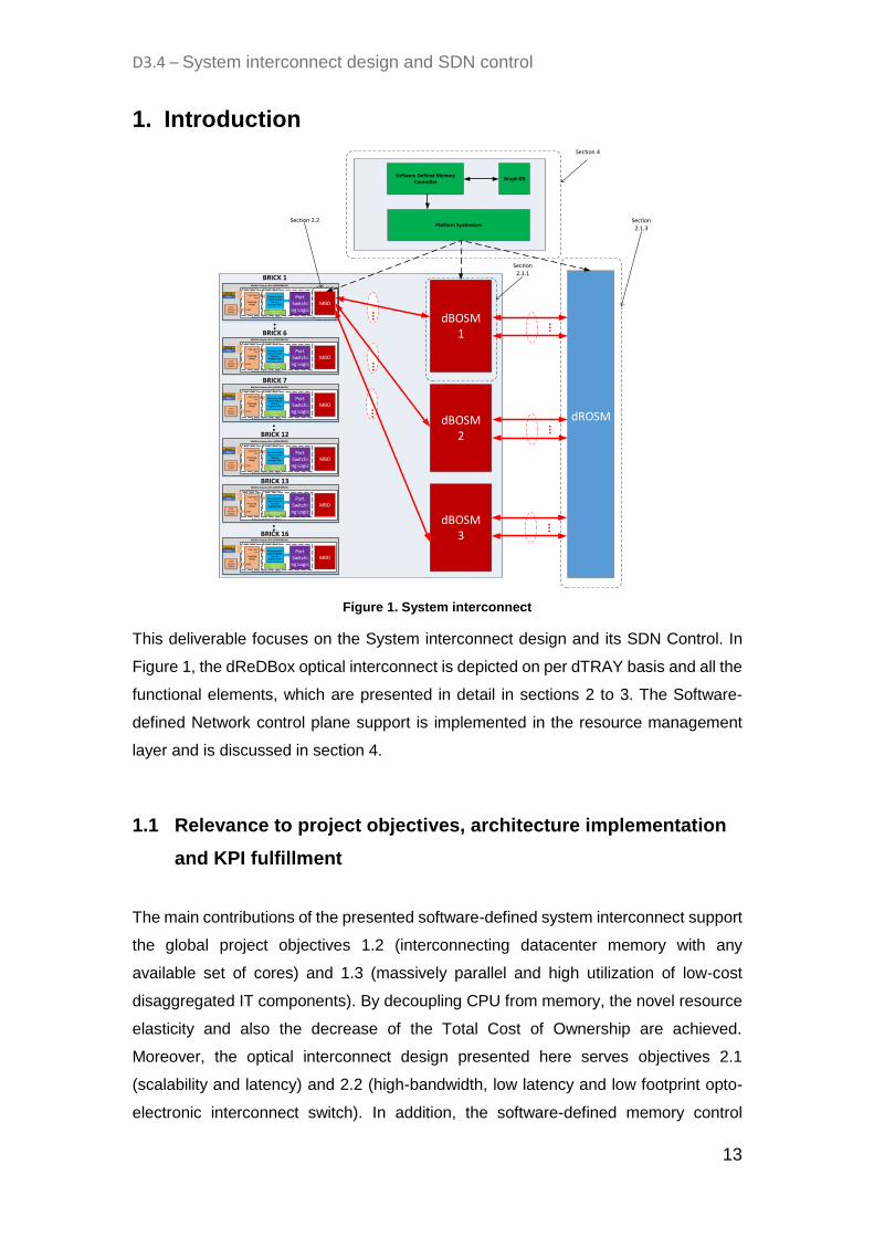
1. Introduction
Figure 1. System interconnect
This deliverable focuses on the System interconnect design and its SDN Control. In
Figure 1, the dReDBox optical interconnect is depicted on per dTRAY basis and all the
functional elements, which are presented in detail in sections 2 to 3. The Software-
defined Network control plane support is implemented in the resource management
layer and is discussed in section 4.
1.1 Relevance to project objectives, architecture implementation
and KPI fulfillment
The main contributions of the presented software-defined system interconnect support
the global project objectives 1.2 (interconnecting datacenter memory with any
available set of cores) and 1.3 (massively parallel and high utilization of low-cost
disaggregated IT components). By decoupling CPU from memory, the novel resource
elasticity and also the decrease of the Total Cost of Ownership are achieved.
Moreover, the optical interconnect design presented here serves objectives 2.1
(scalability and latency) and 2.2 (high-bandwidth, low latency and low footprint opto-
electronic interconnect switch). In addition, the software-defined memory control
...
...
dBOSM1
BRICK 1
..
dBOSM2
dBOSM3
BRICK 6
BRICK 7
..BRICK 12
...
...
...
BRICK 13
..BRICK 16
...
...
dROSM
...
...
...
Processing Unit(s)
Local memory(DDR4)
high-speed bus Port
Switching Logic
Transaction Glue Logic & Remote
Memory Segment Table
Configuration Registers
DDRC
Programmable LogicProcessing System
Xilinx Zynq Ultrascale+ EG MPSOC
Ethernet
PCIe
dReDBox Compute Brick (dCOMPUBRICK)
MBO
Processing Unit(s)
Local memory(DDR4)
high-speed bus Port
Switching Logic
Transaction Glue Logic & Remote
Memory Segment Table
Configuration Registers
DDRC
Programmable LogicProcessing System
Xilinx Zynq Ultrascale+ EG MPSOC
Ethernet
PCIe
dReDBox Compute Brick (dCOMPUBRICK)
MBO
Processing Unit(s)
Local memory(DDR4)
high-speed bus Port
Switching Logic
Transaction Glue Logic & Remote
Memory Segment Table
Configuration Registers
DDRC
Programmable LogicProcessing System
Xilinx Zynq Ultrascale+ EG MPSOC
Ethernet
PCIe
dReDBox Compute Brick (dCOMPUBRICK)
MBO
Processing Unit(s)
Local memory(DDR4)
high-speed bus Port
Switching Logic
Transaction Glue Logic & Remote
Memory Segment Table
Configuration Registers
DDRC
Programmable LogicProcessing System
Xilinx Zynq Ultrascale+ EG MPSOC
Ethernet
PCIe
dReDBox Compute Brick (dCOMPUBRICK)
MBO
Processing Unit(s)
Local memory(DDR4)
high-speed bus Port
Switching Logic
Transaction Glue Logic & Remote
Memory Segment Table
Configuration Registers
DDRC
Programmable LogicProcessing System
Xilinx Zynq Ultrascale+ EG MPSOC
Ethernet
PCIe
dReDBox Compute Brick (dCOMPUBRICK)
MBO
Processing Unit(s)
Local memory(DDR4)
high-speed bus Port
Switching Logic
Transaction Glue Logic & Remote
Memory Segment Table
Configuration Registers
DDRC
Programmable LogicProcessing System
Xilinx Zynq Ultrascale+ EG MPSOC
Ethernet
PCIe
dReDBox Compute Brick (dCOMPUBRICK)
MBO
Software Defined Memory Controller
Graph DB
Platform Synthesizer
...
...
...
Section 2.2
Section 2.1.1
Section 2.1.3
Section 4

D3.4 – System interconnect design and SDN control
14
plane, along with the configurable hardware datapath support that are described here,
serve objectives 3.3 (deep software-defined memory programmability) and partly
support objective 5.1 (global software defined memory resource management).
Eventually, this deliverable presents the progress towards achieving the network KPIs
defined in D2.2 [1] Section 4.3. Table 1 displays the currently achieved values of
network KPIs in conjunction to baseline and target values. In total, current KPIs’ values
are within the reach of target and concerning the optical switch will get even closer, as
the switch “slice” component is still under development.
KPIs Baseline Target Currently
Achieved Description
Optical Switch (Edge of Tray)
Port count 48 96 48
[Note1]
Port dimension of
optical switches
Module
volume per
port
28 cm3 /port 14 cm3/port 25 cm3 /port
[Note1]
Physical size
dimension of optical
switch module
Operating
frequencies
1260–1675
nm 1260–1675 nm 1260–1675 nm
Bandwidth range that
the switch can
operate.
Typical
insertion loss 1 dB 1 dB 1 dB
Input to output port
loss
Crosstalk < -50dB < -50 dB < -50 dB
Power coupled from
input port to
unintended output
port
Switching
configuration
time
25 ms 25 ms 25 ms
Time required to set-
up port cross-
connections
Switching
latency 10 ns 10 ns 10 ns
Optical switching
latency once in/out
ports are configured
Power
consumption 100mW/port 50mW/port
100mW/port
[Note1]
Power consumption
per port

D3.4 – System interconnect design and SDN control
15
Optoelectronic Transceivers
Capacity 100 Gb/s 200 Gb/s 200 Gb/s Transmitting capacity
of transceiver
Bandwidth
Density
0.02
Gb/s/mm2 0.2 Gb/s/mm2 0.2 Gb/s/mm2
Bandwidth space
efficiency of a
transceiver
Power
budget
Varies per
type of
module
10 dB
12 dB @ 16
Gb/s
8 dB @ 25 Gb/s
Otherwise called
attenuation
allowance. Maximum
distance and/or
switching hops signal
can travel within the
network with bit error
rate free operation
(<1E-9)
Table 1. Network KPIs
Notes: [Note1] This value has reduced slightly because of a slightly smaller case design for the
current generation 48-port module. The improved and more integrated switch internals (based on the “slice” component) are still being developed. When that has been done then the KPI targets (e.g. 96 ports, 14cm3 housing volume and 50mW power consumption per port) will be achieved.
2. dReDBox Switching Technologies
2.1 Optical switches
Within the dReDBox solution there is a requirement to achieve reconfigurable, high-
bandwidth, low-latency, point-to-point, duplex optical fibre connectivity between any
one of the eight optical interfaces (presented via the mid-board optics modules
described in Section 2.2) between any two dBRICKs in a given dReDBox installation.
This arises from dReDBox requirements: Memory-nf-06, Memory-nf-08, Network-f-01,
Network-f-02, Network-nf-01, Network-nf-02, Network-nf-04. In order to ensure that the
D3.4 – System interconnect design and SDN control
16
optical switching fabric that provides this connectivity is both ultimately scalable and
economical from an operational perspective (i.e. it needs to be possible to grow the
fabric as needed without needing to impose service breaks) then a modular, multi-
stage, low-loss optical circuit switching fabric has been designed for implementation in
dReDBox installations. This fulfils dReDBox requirements: Memory-nf-10, Network-f-
05, Network-nf-03, Network-nf-05, Network-nf-06.
This fabric is most efficiently implemented in multiple stages thereby allowing in-
service switching fabric capacity upgrade and for the individual switching elements to
be distributed throughout the racks housing all the compute, memory and acceleration
bricks. Three stages are sufficient to implement the largest dReDBox installations as
discussed in D2.4 [2] (and illustrated in Figure 17 in this deliverable). This requires that
the insertion loss of each switching stage is as low as possible. The low insertion loss
of the DirectLight™ optical circuit switching technology from project partner
HUBER+SUHNER Polatis used in dReDBox is suitable to fulfil this particular
requirement.
The fundamental optical switching technology at the heart of the Polatis module is
based on their patented DirectLight™ “beam steering” in which arrays of fibers
terminated with high-quality collimating lenses are directed at each other across a
small air gap. The steering of the collimators is realized using piezo electric actuators
with a high precision position detection mechanism and a fast closed-loop control to
facilitate fast and accurate re-positioning of the collimators during switching operations
and to maintain their orientation between switching operations. The fundamental
building block used to construct these arrays is a small linear array of 12 or 16 such
actuators called a “slice”.
In the “core” of a regular symmetric NxN or asymmetric NxM switch the slices are
arranged in two opposing 2D arrays of optical ports separated by an air gap. In most
(non-blocking) configurations, any given port in one array can be directed at any of the
ports in the opposite array. The ports of one array are usually denoted as “input ports”
and those in the other array are denoted as “output ports”. This gives rise to a high
radix bidirectional optical switching function.
The bidirectionality here refers to the fact that the switch core supports the switching
of regular duplex optical signal transmission using pairs of fibre (this will utilize four
ports out of the two arrays) and also supports the switching of bidirectional optical
D3.4 – System interconnect design and SDN control
17
signal transmission using a single fibre (sometimes referred to as “single fibre working”
– e.g. where transmission in one direction may be done at a different frequency to
transmission in the other)1.
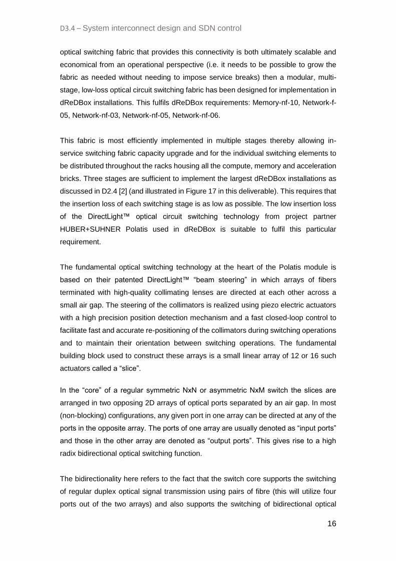
However, in one of these regular NxN or NxM switches, a port cannot be directed at
another port in the same array. In other words, an input port cannot be connected to
another input port and likewise for two output ports. This is illustrated in Figure 2.
Figure 2. An NxN Polatis optical switch core schematic
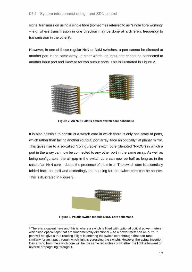
It is also possible to construct a switch core in which there is only one array of ports,
which rather than facing another (output) port array, face an optically flat planar mirror.
This gives rise to a so-called “configurable” switch core (denoted “NxCC”) in which a
port in the array can now be connected to any other port in the same array. As well as
being configurable, the air gap in the switch core can now be half as long as in the
case of an NxN core – due to the presence of the mirror. The switch core is essentially
folded back on itself and accordingly the housing for the switch core can be shorter.
This is illustrated in Figure 3.
Figure 3. Polatis switch module NxCC core schematic
1 There is a caveat here and this is where a switch is fitted with optional optical power meters which use optical taps that are fundamentally directional – so a power meter on an output port will not give a true reading if light is entering the switch core through that port (and similarly for an input through which light is egressing the switch). However the actual insertion loss arising from the switch core will be the same regardless of whether the light is forward or reverse propagating through it.

D3.4 – System interconnect design and SDN control
18
Switching elements utilizing both such kinds of cores (“NxN” and “configurable”) are
being used in the dReDBox optical circuit switching fabric.
The insertion loss of a path between any two ports is determined by many factors
including the length of the optical path through the core, variations in the components,
variations in the alignment of components during manufacturing, variations in the
splices made between the fibre tails emerging from the switch core and the optical
connectors. Hence there is a Gaussian distribution of insertion losses.
HUBER+SUHNER Polatis work very hard to minimize both the width and the median
value of the distribution as well as maximize the repeatability of the insertion loss for a
given pair of ports between switching operations. Figure 4 shows these values for a
192x192 port Series 6000 switch for which the median insertion loss is just less than
1.0dB. The median insertion loss for the 384x384 port switch is 1.5dB.
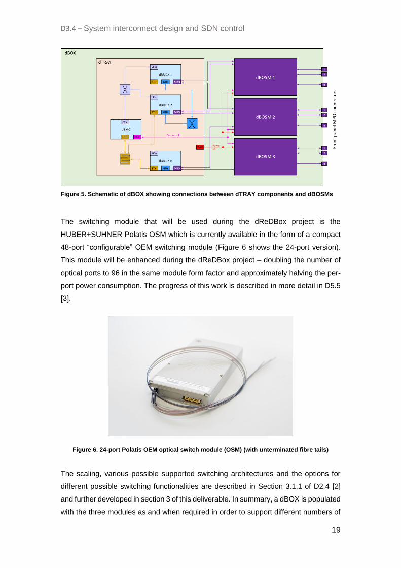
2.1.1 dBOSM specification
The dBOSM or dBOX Optical Switching Module provides the optical switching function
within a dBOX – sometimes referred to as “edge-of-tray” or EoT switching. Actually a
dBOX will house up to three dBOSMs (as shown in Figure 5) and they constitute the
first stage of switching in the multi-stage optical switching fabric at the core of a
dReDBox installation.
Figure 4. Insertion loss statistics for a H+S Polatis Series 6000 192x192 port optical switch
D3.4 – System interconnect design and SDN control
19
Figure 5. Schematic of dBOX showing connections between dTRAY components and dBOSMs
The switching module that will be used during the dReDBox project is the
HUBER+SUHNER Polatis OSM which is currently available in the form of a compact
48-port “configurable” OEM switching module (Figure 6 shows the 24-port version).
This module will be enhanced during the dReDBox project – doubling the number of
optical ports to 96 in the same module form factor and approximately halving the per-
port power consumption. The progress of this work is described in more detail in D5.5
[3].
Figure 6. 24-port Polatis OEM optical switch module (OSM) (with unterminated fibre tails)
The scaling, various possible supported switching architectures and the options for
different possible switching functionalities are described in Section 3.1.1 of D2.4 [2]
and further developed in section 3 of this deliverable. In summary, a dBOX is populated
with the three modules as and when required in order to support different numbers of

D3.4 – System interconnect design and SDN control
20
dBRICKs, different resilience options and different optical circuit blocking probabilities.
A minimal configuration for a single dBOX is one 48- or 96-port dBOSM at initial
installation. The second and third dBOSM can be installed in the dBOX at a later time
in a non-service-interrupting in-field upgrade when more dBRICKs are added and/or
options for resilient optical circuit switching to remote dBRICKs are required. For
example, the optical interconnects shown in Figure 5 (purple lines) illustrate the most
redundant configuration – each dBRICK has an MBO module with two MPO/MPT
connectors each of which is connected to two separate dBOSMs. Each MPO/MPT
connector carries eight active fibres (4 transmit and 4 receive in respect of the MBO
transceivers).
Optical interconnects from the dBOSMs to the dROSM(s) are also based on 8-fibre
ribbons using MPO/MPT connectors. These are presented on the front panel of the
dBOX. In order to ensure that there are no unnecessary MPO/MPT connections within
the dBOX, the dBOSMs will be manufactured with fibre ribbon tails of a suitable length
to comfortably allow cable routing within the dBOX enclosure whilst not having too
much excess cable length to manage.
The dBOSMs are powered from risers on the dTRAY (12V, up to 15W) and controlled
by the dBMC via RS232 serial connections presented on the dTRAY. The module
shown in Figure 6 is fitted with an external breakout board during manufacture which
is used (in different forms) to present different connector options for power and
communications. The option that is probably most suitable for the dBOSM is one on
which a Molex KK 254 series 3-pin, 2.54mm pitch header is used for communications
and a 4-pin, 3mm pitch Micro MATE-N-LOK vertical riser is used for the power
connection. This is shown in Figure 7. The leads can then be neatly routed within the
dBOX enclosure to the power risers on the dTRAY and the communications
connection risers on the dBMC.
Figure 7. Power and communications external breakout board for Polatis OSM
D3.4 – System interconnect design and SDN control
21
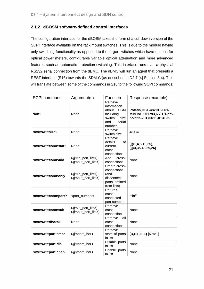
2.1.2 dBOSM software-defined control interfaces
The configuration interface for the dBOSM takes the form of a cut-down version of the
SCPI interface available on the rack mount switches. This is due to the module having
only switching functionality as opposed to the larger switches which have options for
optical power meters, configurable variable optical attenuation and more advanced
features such as automatic protection switching. This interface runs over a physical
RS232 serial connection from the dBMC. The dBMC will run an agent that presents a
REST interface (S16) towards the SDM-C (as described in D2.7 [4] Section 3.4). This
will translate between some of the commands in S16 to the following SCPI commands:
SCPI command Argument(s) Function Response (example)
*idn? None
Retrieve information about OSM including switch size and serial number
Polatis,OST-48xCC-LU1-MMHNS,001793,6.7.1.1-dev-polatis-20170611-013105
:oxc:swit:size? None Retrieve switch size
48,CC
:oxc:swit:conn:stat? None
Retrieve details of current cross-connections
(@1,4,5,10,25), (@3,35,48,29,26)
:oxc:swit:conn:add (@<in_port_list>), (@<out_port_list>)
Add cross-connections
None
:oxc:swit:conn:only (@<in_port_list>), (@<out_port_list>)
Create cross-connections (and disconnect ports omitted from lists)
None
:oxc:swit:conn:port? <port_number>
Returns cross-connected port number
“19”
:oxc:swit:conn:sub (@<in_port_list>), (@<out_port_list>)
Remove cross-connections
None
:oxc:swit:disc:all None Remove all cross-connections
None
:oxc:swit:port:stat? (@<port_list>) Retrieve state of ports in list
(D,E,F,E,E) [Note1]
:oxc:swit:port:dis (@<port_list>) Disable ports in list
None
:oxc:swit:port:enab (@<port_list>) Enable ports in list
None
D3.4 – System interconnect design and SDN control
22
Table 2. SCPI commands for dBOSM for managing cross-connections
In the commands above a port list takes the form of (@A,B,C,D) or (@A:Z) for a range
of ports between A and Z.
Note1 The response to the port state query is D for disabled, E for enabled and F for failed.
2.1.3 dROSM/dDOSM specification
The dROSM or dReDBox Rack Optical Switch Module provides the optical switching
function between dBOXes in a single rack or in a number of racks. Depending on how
much redundancy is required in the optical switching fabric in a particular dReDBox
installation, there can even be two dROSMs per dRACK. The dROSMs constitute the
second stage of the dReDBox optical switching fabric.
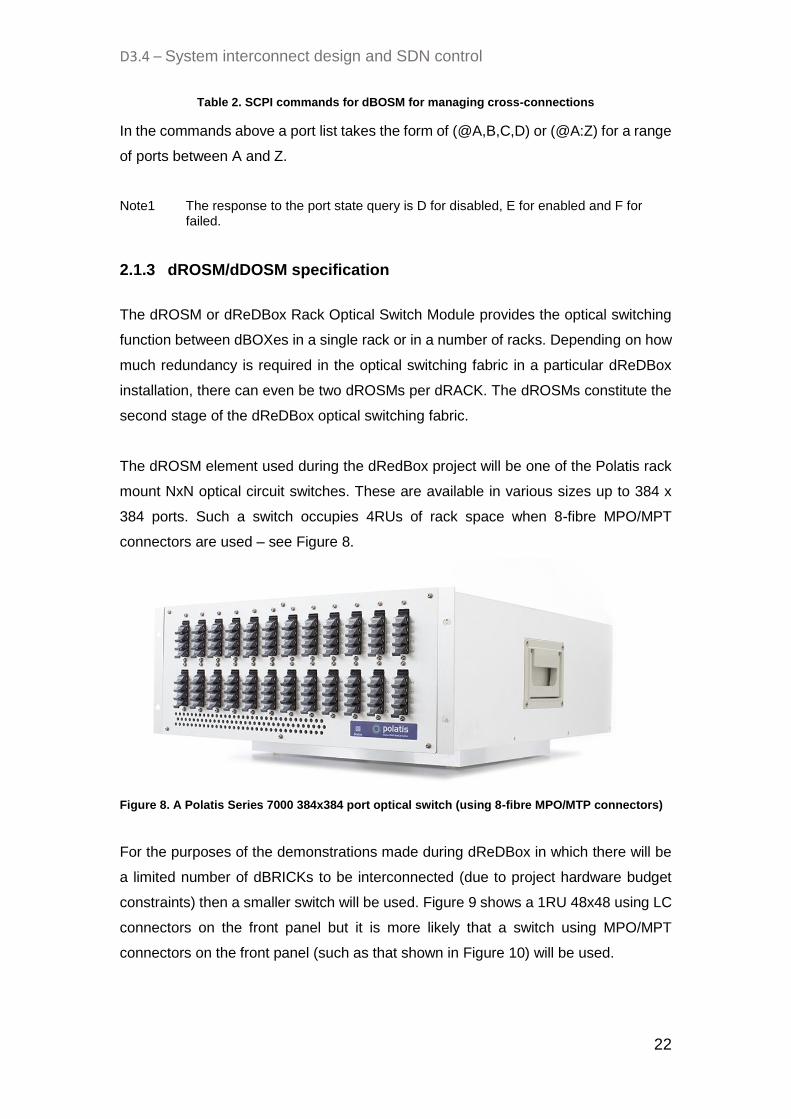
The dROSM element used during the dRedBox project will be one of the Polatis rack
mount NxN optical circuit switches. These are available in various sizes up to 384 x
384 ports. Such a switch occupies 4RUs of rack space when 8-fibre MPO/MPT
connectors are used – see Figure 8.
Figure 8. A Polatis Series 7000 384x384 port optical switch (using 8-fibre MPO/MTP connectors)
For the purposes of the demonstrations made during dReDBox in which there will be
a limited number of dBRICKs to be interconnected (due to project hardware budget
constraints) then a smaller switch will be used. Figure 9 shows a 1RU 48x48 using LC
connectors on the front panel but it is more likely that a switch using MPO/MPT
connectors on the front panel (such as that shown in Figure 10) will be used.

D3.4 – System interconnect design and SDN control
23
Figure 9. 48x48 port Series 6000 Polatis optical switch (LC connectors)
Figure 10. 48x48 port Series 6000 Polatis optical switch (MPO/MPT connectors)
dDOSM As dReDBox installations grow beyond a single rack then the dReDBox optical
interconnect architecture requires a third stage of switching. This is provided by one or
more dDOSMs (dReDBox Datacentre Optical Switch Modules). These will be
functionally identical to the dROSM and controlled in the same way (directly from the
SDM-C via interface S1).
Low radix switch module option The rack mount switches shown above are all high radix – a given input port can be
connected to ANY of the output ports. Another way of stating this is that where the
input and output ports are respectively used for duplex fibre pair connections then any
duplex pair can be connected to any other duplex pair. This flexibility comes at a cost
in terms of complexity of switch core design (and hence per-port cost) as well as
slightly higher insertion loss to accommodate the necessary larger free space air gap
within the core.
Given that the network on a chip implemented within the PL part of the MP-SoC
supports full on-brick switching between any of the GTH ports and any of the optical
transceivers in the MBO, then the optical switching fabric can essentially be split into
a number of parallel switching planes (dubbed dPLANEs) between which the switches
that constitute the three stages need not provide any connectivity. (This has previously
been mentioned in D2.4 [2] Section 3.1.1 and is further explored in section 3 of this
deliverable.) In other words, a node in the dROSM (2nd) and dDOSM (3rd) switching
stages can be composed of a number of multiple numbers of smaller, lower radix
switches – either smaller rack mount switches (such as 1RU 48x48 or even using the

D3.4 – System interconnect design and SDN control
24
same module as used for the dBOSM). Another appealing aspect of this approach is
that switching nodes can be built up in a pay-as-you-grow manner rather than requiring
the upfront installation of a single high radix switch carrying with it a higher upfront
infrastructure investment cost.
The highest density achievable (per RU of rack space) is where 96-port OSMs (as will
be used for the dBOSM) are used. This will provide, on average, up to 414 optical ports
per RU but, in reality, this value will vary over stages of scale-up due to the details of
needing to grow in increments of one OSM per parallel switching plane and being able
to conveniently house, power and control these modules. Since these modules will
only have the basic SCPI-over-RS232 control interface then a scheme to efficiently
control these modules would be required. This could take the form of a bespoke
housing like the dBOX in which a specialized dBMC with multiple UARTs is located.
2.1.4 dROSM software-defined control interfaces
The NIC (Network Interface Controller) is the onboard high level switch controller found
in the Polatis rack mount optical switches. It is an embedded Linux platform running
on bespoke ARM-based hardware and can be fitted into the switch on its own or as
part of a redundant pair (as shown in Figure 9). It supports many different software
interfaces for the management of the switch as illustrated in Figure 11.
Figure 11. North bound interfaces (user services) supported by NIC in Polatis switch
As described in D2.7 [4] (Section 3.4), the dROSM will be controlled directly by the
software defined memory controller (SDM-C) via interface S1. Moreover, the
functionalities in the dROSM needing to be controlled will be broadly very similar to
those exploited in the dBOSM. Accordingly, even though it is possible to use a higher-

D3.4 – System interconnect design and SDN control
25
level interface such as NETCONF or RESTCONF for this purpose it makes more sense
to use the SCPI interface. The reason for this is that the S1 interface then becomes
almost identical to the interface that will exist within the dBOX between the dBMC and
the dBOSM. The same proxy logic and code can then be used to bind the S1 interface
into the SDM-C as will be used on the dBMC to translate between the relevant REST
calls in S16 and the serial (“SCPI over RS232”) interface used to manage the Polatis
optical switch module.
The only difference between the use of SCPI to control the dBOSM and its use to
control the dROSM is that in the latter case the protocol runs over a TCP/IP session
(transported over the dReDBox Ethernet management network) rather than the
physical RS232 interface.
2.2 BRICK Transceiver driver/control and Phy
In this section, an overview of the optical transceivers employed in dReDBox platform
is provided. At first, the current approach of data centers using pluggable modules is
described, while highlighting the advantages of transceivers integrated in Mid Board
Optics. Next, a detailed specification of the selected transceiver along with the
description of the control interface used to manage it is given and, finally, a
performance comparison of the dReDBox Mid Board Optics technology against
available pluggable options justifies ours selection.
2.2.1 Technology description and plan
To achieve power and space efficiency, the intra data centre communication systems
are currently being dominated by pluggable form factor transceivers. Such
interconnect technologies have evolved from older modules such as SFP+ (10 Gb/s)
to more advanced variants such as SFP28 (25 Gb/s). Nevertheless, standardisation
activities are under way for the development of interconnects capable of operating at
50-200 Gb/s. However, with the continuous growth of traffic over intra data centre
links, the concurrent use of pluggable form transceivers can lead to front-panel and
packaging bottlenecks. In such pluggable form modules, the long and high-frequency
links interconnecting the application-specific integrated circuits (ASICs) to the optical
transceivers can lead to more complex, larger and more power hungry devices. An
efficient approach for the realisation of a cost, space and energy efficient data centre
architecture would be the replacement of pluggable form interconnects by transceivers
integrated into Mid Board Optics (MBO’s) modules.
D3.4 – System interconnect design and SDN control
26
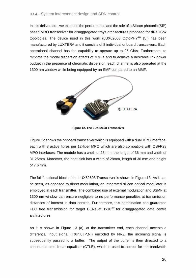
In this deliverable, we examine the performance and the role of a Silicon photonic (SiP)
based MBO transceiver for disaggregated trays architectures proposed for dReDBox
topologies. The device used in this work (LUX62608 OptoPHYTM [5]) has been
manufactured by LUXTERA and it consists of 8 individual onboard transceivers. Each
operational channel has the capability to operate up to 25 Gb/s. Furthermore, to
mitigate the modal dispersion effects of MMFs and to achieve a desirable link power
budget in the presence of chromatic dispersion, each channel is also operated at the
1300 nm window while being equipped by an SMF compared to an MMF.
Figure 12. The LUX62608 Transceiver
Figure 12 shows the onboard transceiver which is equipped with a dual MPO interface,
each with 8 active fibres per 12-fiber MPO which are also compatible with QSFP28
MPO interfaces. The module has a width of 28 mm, the length of 36 mm and width of
31.25mm. Moreover, the heat sink has a width of 28mm, length of 36 mm and height
of 7.6 mm.
The full functional block of the LUX62608 Transceiver is shown in Figure 13. As it can
be seen, as opposed to direct modulation, an integrated silicon optical modulator is
employed at each transmitter. The combined use of external modulation and SSMF at
1300 nm window can ensure negligible to no performance penalties at transmission
distances of interest in data centres. Furthermore, this combination can guarantee
FEC free transmission for target BERs at 1x10-12 for disaggregated data centre
architectures.
As it is shown in Figure 13 (a), at the transmitter end, each channel accepts a
differential input signal (TX[n:0][P,N]) encoded by NRZ, the incoming signal is
subsequently passed to a buffer. The output of the buffer is then directed to a
continuous time linear equaliser (CTLE), which is used to correct for the bandwidth

D3.4 – System interconnect design and SDN control
27
limitations imposed on the system by the band-limited RF devices and the channel.
The transmitter also offers the option to apply retiming to the equalised transmit signal
using a clock and data recovery (CDR) unit. At the last stage, the retimed signal is
subsequently sent to a driver which runs the external integrated modulator. At the
receiver side, the photodetected signal is sent to a transimpedance amplifier (TIA)
followed by a linear amplifier (LA) which is used to further boost the signal level. Each
receiver in the MBO also provides the option for the retiming of the received signal
using a second CDR module. Finally, to further alleviate the effects of the channel, a
pre-emphasis module is also used before the generation of the differential output
signals (RX[7:0][P,N]).
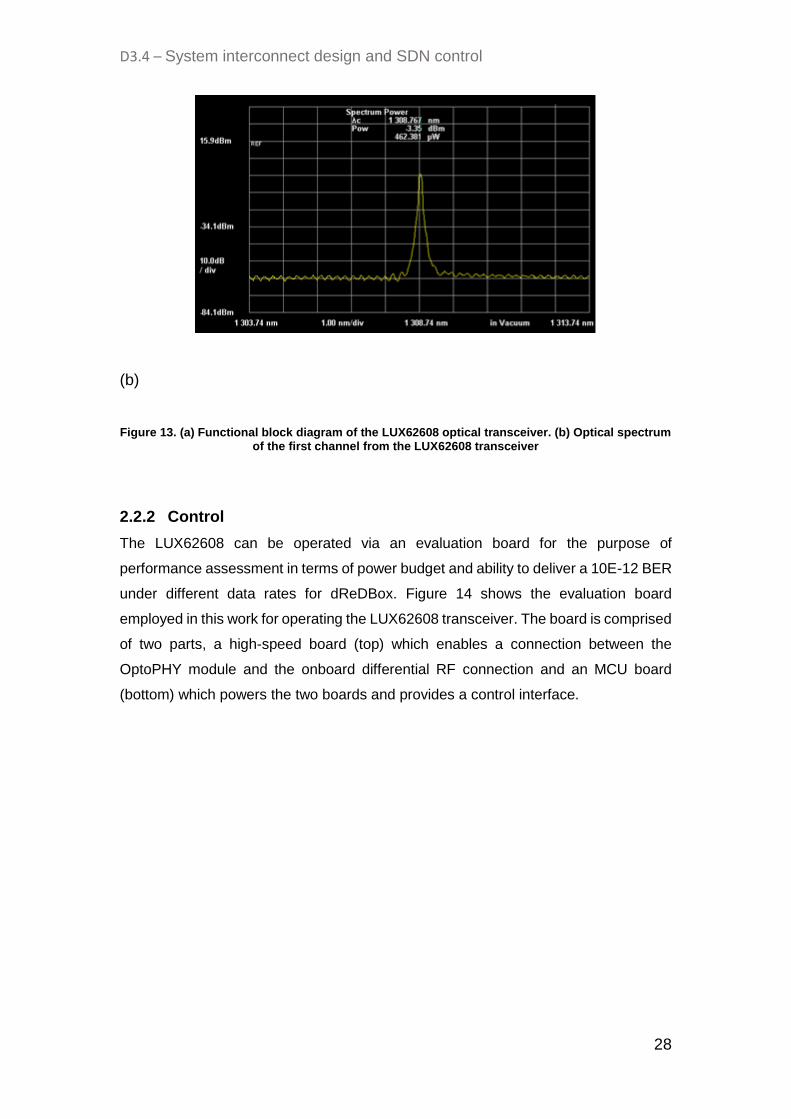
Figure 13 (b) shows the optical spectrum from the first channel of the MBO, all
channels share a common wavelength at 1308.7 nm and an OSNR of 61 dB.
(a)
D3.4 – System interconnect design and SDN control
28
(b)
Figure 13. (a) Functional block diagram of the LUX62608 optical transceiver. (b) Optical spectrum of the first channel from the LUX62608 transceiver
2.2.2 Control
The LUX62608 can be operated via an evaluation board for the purpose of
performance assessment in terms of power budget and ability to deliver a 10E-12 BER
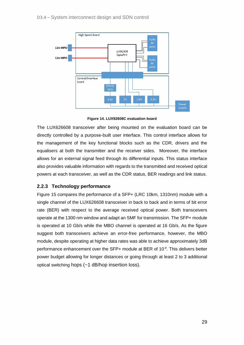
under different data rates for dReDBox. Figure 14 shows the evaluation board
employed in this work for operating the LUX62608 transceiver. The board is comprised
of two parts, a high-speed board (top) which enables a connection between the
OptoPHY module and the onboard differential RF connection and an MCU board
(bottom) which powers the two boards and provides a control interface.
D3.4 – System interconnect design and SDN control
29
Figure 14. LUX92608C evaluation board
The LUX626608 transceiver after being mounted on the evaluation board can be
directly controlled by a purpose-built user interface. This control interface allows for
the management of the key functional blocks such as the CDR, drivers and the
equalisers at both the transmitter and the receiver sides. Moreover, the interface
allows for an external signal feed through its differential inputs. This status interface
also provides valuable information with regards to the transmitted and received optical
powers at each transceiver, as well as the CDR status, BER readings and link status.
2.2.3 Technology performance
Figure 15 compares the performance of a SFP+ (LRC 10km, 1310nm) module with a
single channel of the LUX626608 transceiver in back to back and in terms of bit error
rate (BER) with respect to the average received optical power. Both transceivers
operate at the 1300 nm window and adapt an SMF for transmission. The SFP+ module
is operated at 10 Gb/s while the MBO channel is operated at 16 Gb/s. As the figure
suggest both transceivers achieve an error-free performance, however, the MBO
module, despite operating at higher data rates was able to achieve approximately 3dB
performance enhancement over the SFP+ module at BER of 10-9. This delivers better
power budget allowing for longer distances or going through at least 2 to 3 additional
optical switching hops (~1 dB/hop insertion loss).

D3.4 – System interconnect design and SDN control
30
Figure 15. Performance comparison of a SFP+ module with a single channel from the MBO transceiver in a back to back configuration
Figure 16 presents the performance of a single channel from the MBO in a back to
back configuration while its operated at 25 Gb/s. By comparing this figure with Figure
15, it is clear that the bandwidth extension from the 16 Gb/s system results in
approximately 5 dB of performance penalty. Nevertheless, BER trends approaching
10-12 are observed in both cases, demonstrating error free performance. As this figure
further shows, the activation of the CDR module both at the transmitter and the receiver
ends can further enhance the performance (1dB at BER of 10-9).
Figure 16. Performance of the MBO transceiver in presence and absence of the CDR block
Table 3 compares the MBO technology used in this work with other currently available
alternatives such as QSFP28, SFP+ and CFP4. As it’s apparent, mid board optics can
offer superior bandwidth density and energy efficiency compared to the
pluggable options, making MBOs an excellent choice for next generation
disaggregated data centre communications.
D3.4 – System interconnect design and SDN control
31
Module QSFP28 SFP+ CFP4 OptoPHY®
Line rate 4x25G 1x10G 4x25G 8x25G
BW volume (Mbps/mm3) 12.6 1.6 4.9 15.5
Energy Efficiency (pj/bit) 35 140 50 23
Table 3. Transceiver comparison
3. Network simulation analysis
3.1 Standard multi-tier vs parallel architecture
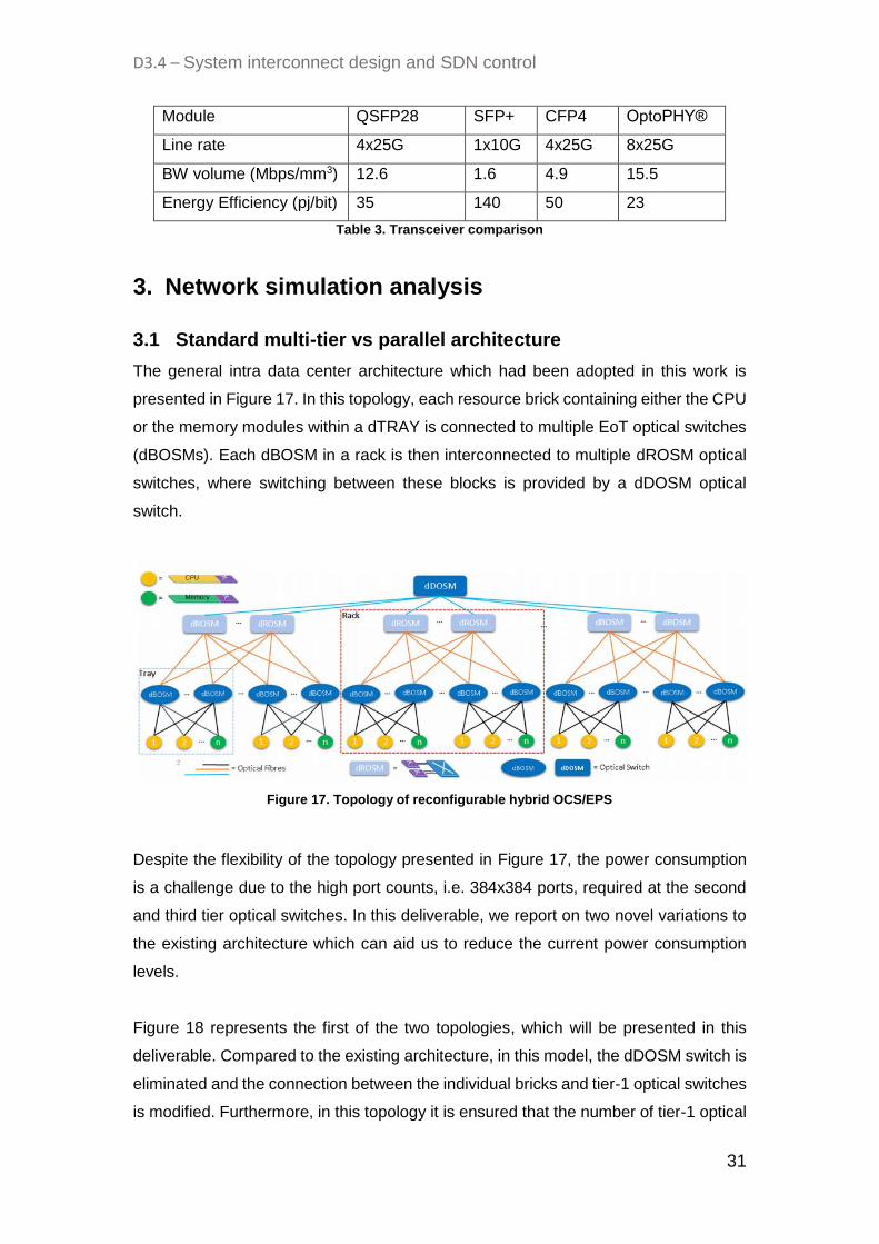
The general intra data center architecture which had been adopted in this work is
presented in Figure 17. In this topology, each resource brick containing either the CPU
or the memory modules within a dTRAY is connected to multiple EoT optical switches
(dBOSMs). Each dBOSM in a rack is then interconnected to multiple dROSM optical
switches, where switching between these blocks is provided by a dDOSM optical
switch.
Figure 17. Topology of reconfigurable hybrid OCS/EPS
Despite the flexibility of the topology presented in Figure 17, the power consumption
is a challenge due to the high port counts, i.e. 384x384 ports, required at the second
and third tier optical switches. In this deliverable, we report on two novel variations to
the existing architecture which can aid us to reduce the current power consumption
levels.
Figure 18 represents the first of the two topologies, which will be presented in this
deliverable. Compared to the existing architecture, in this model, the dDOSM switch is
eliminated and the connection between the individual bricks and tier-1 optical switches
is modified. Furthermore, in this topology it is ensured that the number of tier-1 optical

D3.4 – System interconnect design and SDN control
32
switches matches the total number of dBOXes in the network. Moreover, the tier-1 and
tier-2 switches are also grouped into individual planes (dPLANE). Another
configuration that should be ensured in this architecture is that the number of
transceivers per brick should equal the number of dPLANEs. In forming the connection
between the dPLANEs and the dBOXes, it is made sure that the first tier-1 optical
switch of all dPLANEs connects to all of the bricks housed in the first dBOX and its
similarly ensured that the second tier-1 optical switch of all dPLANEs connects to all
bricks operating in the second dBOX. The same procedure is repeated for all tier-1
switches and dBOXes as shown in Figure 18.
Figure 18. dBOX modular topology
The second topology, which is presented in this deliverable, is depicted in Figure 19.
In this architecture, it should be ensured that the number of tier-1 switches in one
dPLANE is the same as the number of dBRICKs in a single dBOX, and the number of
dPLANEs matches the number of transceivers per dBRICK. Moreover, to form the
connection between the dPLANEs and the dBOXes, it should be guaranteed that the
first tier-1 optical switch of each dPLANE is connected to the first dBRICK in each
dBOX . The same connection style should be followed for all other tier-1 switches and
dBRICKs, as shown in Figure 19.
It is important to highlight that both architectures proposed on Figure 19 and 20 can
use small scale switches i.e. 96-ports throughout. This makes the architecture
substantially more modular and power efficient since a system can deploy and use
switch ports more effectively.

D3.4 – System interconnect design and SDN control
33
Figure 19. dBRICK modular topology
To determine the power efficiency achievable by these two proposed topologies
compared to the standard architecture previously presented, we carry out a set of
simulations. These simulations account for various subscriber ratios (1:1, 1.4:1, 2:1)
and different number of utilized dBOXes and dBRICKs in the network. Figure 20
presents the resulting trends obtained from these simulations. It can be clearly seen
that the un-parallel topology endures a higher level of power consumption compared
to the two parallel topologies which experience a similar trend. Although, lower power
is consumed when the subscriber ratio tends towards the 2:1 ratio (as result of a lower
overall power count), the unparalleled system still consumes higher power as
compared to the parallel case.
(a)
D3.4 – System interconnect design and SDN control
34
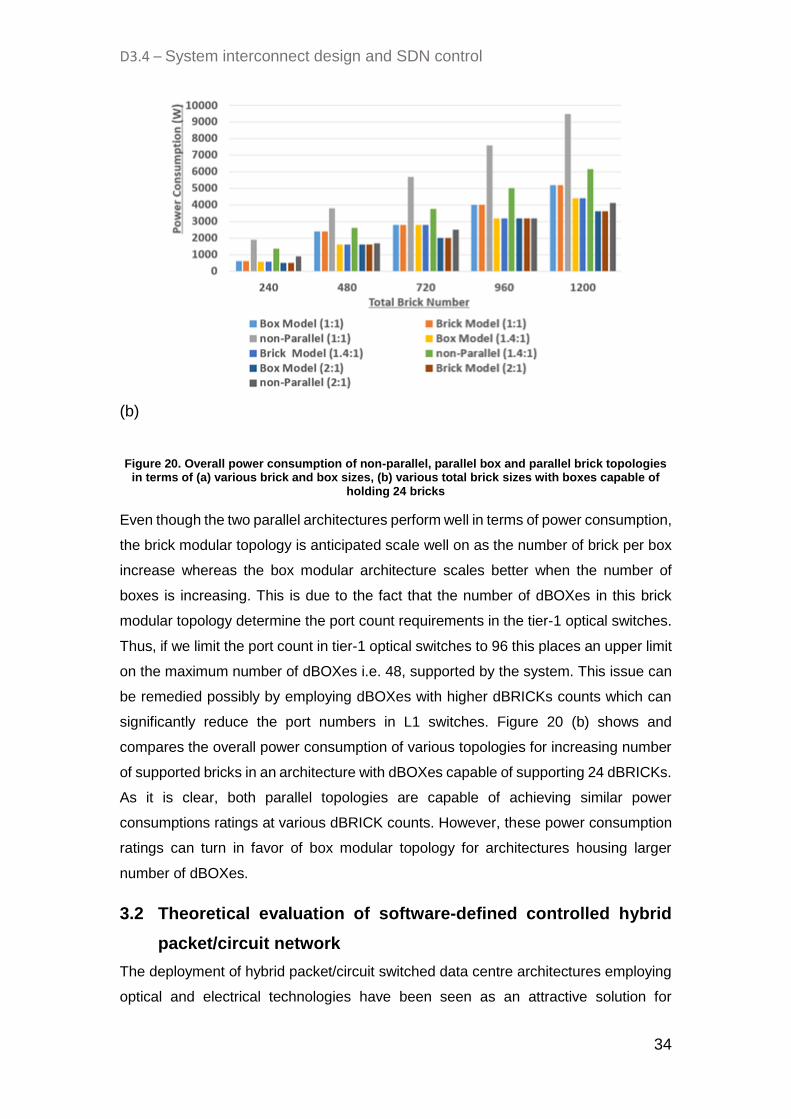
(b)
Figure 20. Overall power consumption of non-parallel, parallel box and parallel brick topologies in terms of (a) various brick and box sizes, (b) various total brick sizes with boxes capable of
holding 24 bricks
Even though the two parallel architectures perform well in terms of power consumption,
the brick modular topology is anticipated scale well on as the number of brick per box
increase whereas the box modular architecture scales better when the number of
boxes is increasing. This is due to the fact that the number of dBOXes in this brick
modular topology determine the port count requirements in the tier-1 optical switches.
Thus, if we limit the port count in tier-1 optical switches to 96 this places an upper limit
on the maximum number of dBOXes i.e. 48, supported by the system. This issue can
be remedied possibly by employing dBOXes with higher dBRICKs counts which can
significantly reduce the port numbers in L1 switches. Figure 20 (b) shows and
compares the overall power consumption of various topologies for increasing number
of supported bricks in an architecture with dBOXes capable of supporting 24 dBRICKs.
As it is clear, both parallel topologies are capable of achieving similar power
consumptions ratings at various dBRICK counts. However, these power consumption
ratings can turn in favor of box modular topology for architectures housing larger
number of dBOXes.
3.2 Theoretical evaluation of software-defined controlled hybrid
packet/circuit network
The deployment of hybrid packet/circuit switched data centre architectures employing
optical and electrical technologies have been seen as an attractive solution for

D3.4 – System interconnect design and SDN control
35
achieving power efficiency, high bandwidth and low latency. Thus, the integration of
such topologies alongside disaggregated architectures can be foreseen to allow for a
significant paradigm shift to contemporary underutilised data centre architectures. This
approach can then allow for a customizable low power data centre which can deliver
ultra-low latency, high throughput and modularity.
In this section, the evaluation of a hybrid reconfigurable disaggregated rack scale data
centre at scale is presented. Moreover, by using a custom-built simulator the
performance of multiple switching technologies and disaggregated resource
architectures supporting multi-tenancy via Virtual Machine (VM) deployment is
investigated. Figure 21 (a) and (b) illustrate the tray architecture of a pure Optical
Circuit Switched (OCS) and classical statistically dimensioned hybrid systems. In the
OCS architecture, all resources or bricks are connected to the OCS based Edge of
Tray (EoT) via their Mid Board Optic (MBO) modules which provide a pure OCS
interconnection. However, in the classical hybrid tray topology all bricks are connected
partly to one Electronic Packet Switch (EPS) based EOT and partly to one OCS based
EOT. On the other hand, Figure 21 (c) presents the dReDBox tray architecture. The
tray contains embedded CPU on Multiprocessor System on Chip (MPSoC) bricks
(dCOMPUBRICKs), memory bricks (dMEMBRICKs) and EOT. Each dCOMPUBRICK
has embedded CPU cores and FPGA programmable switch interface card that drives
mid-board optics. The programmable logic can configure each of its ports to provide
layer 2 packet switch functionality while the dMEMBRICK only has access with the
MBO.
Figure 21. (a) Pure OCS tray architecture (b) classical statistically dimensioned and configured hybrid tray architecture (c) dReDBox tray (d) dReDBox rack scale architecture
Figure 21 (d) demonstrates the dReDBox disaggregated rack scale architecture,
where the Top of the Rack (ToR) is a higher degree optical switch which provides intra-
rack and inter-rack communications. Heterogeneous racks have both
dCOMPUBRICKs and dMEMBRICKs on one tray, and a homogenous rack has

D3.4 – System interconnect design and SDN control
36
dCOMPUBRICKs only or dMEMBRICKs only on one tray. It should be mentioned that,
the proposed architecture can be configured differently by altering the number of EoT
per tray, transceivers per brick, trays in rack, port configuration of optical switches and
management of MPSoc and memory resource pools per tray.
In this deliverable, a simulator was developed in Matlab for optical network function
synthesis of the proposed hybrid and disaggregated data centre architecture. This
simulator will be used to investigate the best combination of multiplexing ad switching
techniques to process the traffic of the network. This simulator operates by examining
the bandwidth of each flow request made by the Virtual Machine (VM), based on this
evaluation the simulator then decides the optimal routing, switching and multiplexing
strategy which could be either based on EPS, EPS and OCS or OCS only. The
simulator will also decide how to select the dCOMPUBRICK which will be configured
for Layer 2 packet switching. The VM requests are defined to consist of 2
dCOMPUBRICKs and 3 dMEMBRICKs which, these will also determine the location
of each brick in the rack as well as the required bandwidth for each flow. To determine
efficient routing between the various bricks, we consider and build a strategy matrix by
calculating the total bandwidth of flows of data from each of the 2 dCOMPUBRICKs to
the 3 dMEMBRICKs, and also we calculate the bandwidth of flow from each of the 2
dCOMPUBRICKs to a single dMEMBRICK. To achieve a pure EPS routing, the total
bandwidth of flow from the 2 dCOMPUBRICKs to the 3 dMEMBRICKs should be
smaller than the capacity available by the MBOs. Similarly, for EPS routing to be
possible the total bandwidth flow from the 2 dCOMPUBRICKs to a single dMEMBRICK
should be below the capacity of the MBO.
Figure 22. Illustration of possible topologies using (a) EPS (b) a combination of EPS and OCS
Figure 22 demonstrates the possible topology combination for EPS and OCS scenario.

D3.4 – System interconnect design and SDN control
37
Figure 22 (a) illustrates one of the possible topology combination using one
dCOMPUBRICK as a packet switch for accessing 3 dMEMBRICKs via optical EoTs. If
the total bandwidth flow from the two MPSoCs is greater than the capacity of the MBO
on the MPSoC used for EPS, EPS routing will not be possible. Thus, the simulator will
check for MPSoC to MPSoC connection for a different combination of the 2
dMEMBRICKs, and the third dMEMBRICK is connected to the two MPSoCs via OCS
as shown in Figure 22 (b). Lastly, if none of the previous criteria is meet, a pure OCS
routing topology is configured to connect various dBRICKs based on the VM requests.
After, all possible topologies for the VM request are built. For each dBRICK to dBRICK
link to be initiated, the simulator looks for already existing connection in the network to
investigate whether available bandwidth is in place to perform grooming services. If no
dBRICK to dBRICK established paths exists it then allocates available network
resources in a first fit approach. Following this, once all resources are identified for all
links in the current VM request, the request is established. The VM request will only
be rejected if no resources are found for any link for all other possible topology
combinations in a VM request. Lastly, each individual VM request poses a life time and
once this expires the simulator releases all resource assigned to that VM request.
Number of racks 1
Number of trays 4
Bricks per tray 24 (12 MPSoC/12 memory)
Transceivers per MBO 8
Data rate per transceiver 10 Gb/s
Optical EOT port count 192
TOR port count 384
Bandwidth flow per VM request Mice flow (1-5 Gb/s)
Elephant flow (6-10 Gb/s)
Table 4. Simulation parameters for pure OCS rack architecture
The dReDBox and pure OCS architecture is initially simulated. The parameters used
for this simulation are stated in Table 4. Each tray is interconnected to 2 EOT optical
switches, and the 4 trays are interconnected by 2 TOR optical switches. The VM
requests are assumed to follow a poison process with a mean inter-arrival rate of 10
time units and an increasing holding time range of 100-1000 time units with
incremental steps of 100 time units. The link bandwidth for each request flow varies

D3.4 – System interconnect design and SDN control
38
between mice flow and elephant flow. The range of the network request is varied mice
and elephant flows. For 1 to 200 a 0%:100% ratio is considered for Mice flow:Elephant
flow. For 201 to 400 a ratio of 25%:75%, 401 to 700 a ratio of 50%:50%, for 601 to 800
a ratio of 75%:25% and 801 to 1000 a ratio of 100%:0%.
Figure 23. Blocking probability of (a) dReDBox vs pure OCS (b) Heterogeneous vs Homogenous tray (c) Number of used switch ports
Figure 23 presents, the simulations results for the dReDBox architecture and the pure
OCS topology. Figure 23 (a) demonstrates a 7.3 % lower blocking probability for the
dReDBox architecture compared to the pure OCS topology at 1000 holding time, this,
in turn, translates into 16.5% resource saving. Figure 23 (b) shows that regardless of
whether homogenous or heterogeneous trays had been used in the dReDBox system,
a similar performance would result. Nevertheless, it should be considered that the
homogenous tray architectures have more switch ports leading to higher costs and
power consumptions.
3.3 Benchmark against existing hybrid systems
In the next deliverable, a comparison is made between both dReDBox and classical
hybrid tray architecture; the tray again has 12 dCOMPUBRICKs and 12
dMEMBRICKs. Each dBRICK has 32 transceivers which are accommodated by 4
MBO. The dReDBox tray is connected to two optical switches with 384 ports each
while the classical hybrid tray is connected to an EPS switch with 384 ports and an
optical switch with 384 ports. Figure 24 (a) demonstrates that the dReDBox system
achieves a 12.6 % lower blocking probability at 1000 holding time unit then the
classical traditional architecture. Moreover, according to Figure 24 (b) and (c) it can be
clearly seen that the dReDBox architecture achieves 37% improvement in cost and
873% in power consumption due to the reduction of power hungry electronic switches
and additional transceivers required for EPS in the classical architecture.
D3.4 – System interconnect design and SDN control
39
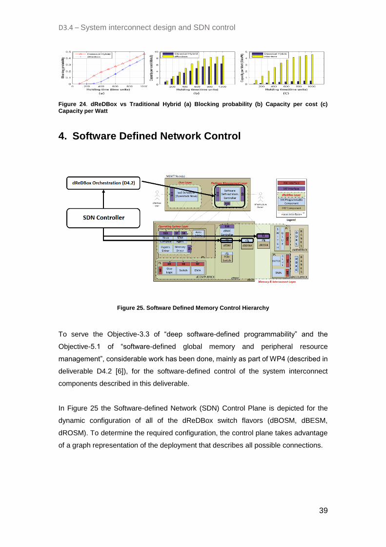
Figure 24. dReDBox vs Traditional Hybrid (a) Blocking probability (b) Capacity per cost (c) Capacity per Watt
4. Software Defined Network Control
Figure 25. Software Defined Memory Control Hierarchy
To serve the Objective-3.3 of “deep software-defined programmability” and the
Objective-5.1 of “software-defined global memory and peripheral resource
management”, considerable work has been done, mainly as part of WP4 (described in
deliverable D4.2 [6]), for the software-defined control of the system interconnect
components described in this deliverable.
In Figure 25 the Software-defined Network (SDN) Control Plane is depicted for the
dynamic configuration of all of the dReDBox switch flavors (dBOSM, dBESM,
dROSM). To determine the required configuration, the control plane takes advantage
of a graph representation of the deployment that describes all possible connections.

D3.4 – System interconnect design and SDN control
40
Figure 26. Graph Representation of Software defined control plane
In Figure 26 a very simple graph representation is depicted for a 2x2 dBOSM or
dBESM switch that interconnects 1 dCOMPUBRICK with 1 dMEMBRICK. When a path
is reserved, the SDM Controller traverses it on the graph to determine the involved
switches and their configuration. Further description of this component is provided in
Section 3.1 of deliverable D4.2 [6].
The aforementioned configurations are then passed to Platform Synthesizer (Section
3.4 of D4.2 [6]), which is responsible for applying them on the dReDBox switches. With
subsequent calls to the dReDBox Baseboard Management Controller exposed API
(interface S16 in D2.7 [4]) will configure the on-tray dBOSM switches or the dBESM
switch, through their respective control interface, for connecting the ports that will
assist in establishing a circuit between dBRICKS. The final component that needs to
be configured is the dROSM switch through its respective interface, a description of
which is provided in Section 2.1.4 of this deliverable.
5. Conclusions This deliverable expanded on the network architecture portrayed in D2.4 [2] and
provided a detailed specification of all the hardware components involved in dReDBox
system optical interconnect enabling a low-latency, scalable network followed by a
comprehensive description of the software interfaces for the software-defined control
of each one, thus enabling the dynamic configuration of the network. Furthermore,
simulation analysis of possible network architectures highlighted the advantages of the

D3.4 – System interconnect design and SDN control
41
dReDBox architecture in both power consumption and cost. In Section 4, a brief
overview of software components developed in WP4, orchestrating the software-
defined configuration of system interconnect, was given. Eventually, the current status
of network KPIs in comparison to the target KPIs underlined the progress towards the
entire fulfillment of project objectives, which should happen once the development
process of the dBOSM optical switch is completed.
D3.4 – System interconnect design and SDN control
42
References
[1] dReDBox consortium, “D2.2 - Requirements specification and KPIs Document(b),”
EU Horizon 2020 dReDBox project, 2016.
[2] dReDBox consortium, “D2.4 - System Architecture specification (b),” EU Horizon
2020 dReDBox project, 2016.
[3] dReDBox consortium, “D5.5 - Intermediate Report of Hardware Development
Progress,” EU Horizon 2020 dReDBox project, 2017.
[4] dReDBox consortium, “D2.7 - Specification of dReDBox layers, operational
semantics and cross-layer interfaces (c),” EU Horizon 2020 dReDBox project,
2017.
[5] Luxtera, "Luxtera OptoPHY," [Online]. Available:
http://www.luxtera.com/luxtera/products. [Accessed 6 2017].
[6] dReDBox consortium, “D4.2 - System Software Architecture, Interfaces and
Techniques (b),” EU Horizon 2020 dReDBox project, 2017.
[7] dReDBox consortium, “D2.6 - Specification of dReDBox layers, operational
semantics and cross-layer interfaces (a),” EU Horizon 2020 dReDBox project,
2016.