d31 - mobinet.eumobinet.eu/sites/default/files/mobinet-del-d31.1-platformreview-v1... · d31.1 3.1...
TRANSCRIPT

D31.1
3.1 Platform state-of-the-art review
7th RTD Framework Programme Directorate General for Communications Networks, Content & Technology Cooperative Systems for energy efficient and sustainable mobility (FP7-ICT-2011-6.7) Contract Type: Collaborative project Grant agreement no.: 318485
Work package: 3.1
Version number: Version 1.1
Dissemination level: PU
Date: 06/10/2014

06/10/14 Page 2 of 104
Version 1.1
Version Control
Version history
Version Date Main author Summary of changes
0.1 08/04/2013 Francesco Alesiani (NEC) FI-WARE analysis and document
structure
0.2 07.08.2013 Francesco Alesiani (NEC) New chapter structure
0.3 02.09.2013 Tobias Schlauch (DLR) Analysis of Instant Mobility project
0.4 13.09.201 Igor Passchier (TNO) Analysis of SPITS and
GOOGLE/APPLE Application store
0.5 23.09.2013 Francesco Alesiani (NEC) Integrated version
0.6 28.10.2013 Francesco Alesiani (NEC) Concluding chapter
1.1 19.09.2014 Francesco Alesiani (NEC) Edited according to the EC review
comments
Name Date
Prepared Francesco Alesiani (NEC) 19/09/2014
Reviewed Yanying Li (ERTICO) 03/10/2014
Authorised Yanying Li (ERTICO) 06/10/2014
Circulation
Recipient Date of submission
European Commission 06/10/2014
Project partners 06/10/2014
Authors
Francesco Alesiani (NEC)
Tobias Schlauch (DLR)
Dirk Beckmann (DLR)
Igor Passchier (TNO)
Eelco Cramer (TNO)

06/10/14
Page 3 of 104 Version 1.1
Table of contents
Version Control ................................................................................... 2
Table of contents ................................................................................ 3
Abbreviations and definitions .............................................................. 6
Executive Summary ............................................................................ 7
1 Introduction ................................................................................... 8
1.1 Document Scope ........................................................................................... 8
1.2 Document Objectives .................................................................................... 8
2 Overview of Relevant Project/Platform .......................................... 9
2.1 Introduction and Method ................................................................................ 9
2.2 Platforms/Products Overview ........................................................................ 9
3 FI-WARE Architecture and Outcomes ......................................... 11
3.1 Introduction .................................................................................................. 11
3.2 FI-WARE Project ......................................................................................... 11
3.3 Future Internet PPP and FI-WARE Platform ............................................... 11
3.4 FI-WARE test bed........................................................................................ 13
3.5 Cloud Hosting (CH) Architecture and components ...................................... 14
3.6 Data Center Resource Management (DCRM) ............................................. 15
3.7 Open Cloud Computing Interface (OCCI) .................................................... 16
3.8 Service Manager (SM) GE .......................................................................... 18
3.9 Cloud Edge (CE) GE ................................................................................... 20
3.10 Object Storage (OS) GE ........................................................................... 21
3.11 Data/Context Management Architecture ...................................................... 23
3.11.1 Context Broker (Publish/Subscribe Broker) GE ............................................... 24
3.11.2 Complex Event Processing (CEP)................................................................... 24
3.11.3 Location GE .................................................................................................... 25
3.11.4 Metadata Preprocessing GE ........................................................................... 26
3.11.5 Compressed Domain Video Analysis GE ........................................................ 28
3.11.6 Media-enhanced Query Broker GE ................................................................. 30
3.11.7 Semantic Annotation GE ................................................................................. 31
3.11.8 Semantic Support GE ..................................................................................... 31
3.12 Internet of Things (IoT) Services Enablement Architecture ......................... 32
3.12.1 Backend IoT Broker GE .................................................................................. 34
3.12.2 Backend Discovery Engine GE ....................................................................... 35
3.12.3 Backend Device Management GE .................................................................. 36
3.12.4 Gateway Device Management GE .................................................................. 37
06/10/14 Page 4 of 104
Version 1.1
3.12.5 Gateway Data Handling GE ............................................................................ 38
3.12.6 Gateway Protocol Adapter GE ........................................................................ 40
3.13 Architecture of Applications and Services Ecosystem and Delivery Framework 41
3.14 USDL (Unified Service Description Language) ............................................ 43
3.15 Security ....................................................................................................... 45
3.15.1 Architecture Overview ..................................................................................... 46
3.16 Interface to Networks and Devices (I2ND) Architecture .............................. 47
3.16.1 Architecture Overview ..................................................................................... 47
3.17 Developer Community and Tools Architecture ............................................ 48
3.17.1 Architecture Overview ..................................................................................... 49
3.18 Outcome Analysis and Conclusions ............................................................ 51
4 SPITS Project Architecture and outcomes ................................... 52
4.1 Introduction .................................................................................................. 52
4.2 Platform Architecture and Outcomes Description ........................................ 53
4.2.1 SPITS platform context ................................................................................... 53
4.2.2 System Scenario ............................................................................................. 54
4.2.3 System Design ................................................................................................ 57
4.2.3.1 The On-board Unit .......................................................................................... 58
4.2.3.2 The Road Side Unit ......................................................................................... 63
4.2.4 Integrated Subsystem Design ......................................................................... 67
4.3 Outcome Analysis and Conclusions ............................................................ 68
5 Android and iOS eco-systems features ....................................... 70
5.1 Introduction .................................................................................................. 70
5.2 Platform Architecture and Outcomes Description ........................................ 70
5.2.1 Installing apps ................................................................................................. 70
5.2.2 How apps can detect other apps installed ....................................................... 71
5.2.3 How apps can communicate with other apps .................................................. 71
5.2.4 How apps can unlock / install new features ..................................................... 72
5.3 Outcome Analysis and Conclusions ............................................................ 73
6 Instant Mobility Architecture and outcomes ................................. 74
6.1 Introduction .................................................................................................. 74
6.2 Platform Architecture and Outcomes Description ........................................ 74
6.2.1 Scenarios ........................................................................................................ 74
6.2.1.1 Personal travel companion .............................................................................. 74
6.2.1.2 Smart city logistics .......................................................................................... 75
6.2.1.3 Transport infrastructure as a service ............................................................... 75
6.2.2 Platform Architecture....................................................................................... 75
6.2.2.1 Architectural Vision ......................................................................................... 76
6.2.2.2 Conceptual Architecture .................................................................................. 78

06/10/14
Page 5 of 104 Version 1.1
6.2.3 Overview of the implemented Prototypes ........................................................ 86
6.2.3.1 Scenario 1 – Personal Travel Companion ....................................................... 86
6.2.3.2 Scenario 2 – Smart City Logistics ................................................................... 90
6.2.3.3 Scenario 3 – Transport Infrastructure as a Service ......................................... 93
6.3 Outcome Analysis and Conclusions ............................................................ 96
ANNEX: Analysis Table .................................................................... 97

06/10/14 Page 6 of 104
Version 1.1
Abbreviations and definitions
Abbreviation Definition
AGPS Assisted Global Positioning System
AoE ATA over Ethernet
CE GE Cloud Edge GE
CEP Complex Event Processing
CH Cloud Hosting
DCRM Data Center Resource Management
DCT Developer Community and Tools
FI-PPP Future Internet Public-Private Partnership
GE Generic Enabler
I2ND Interface to Networks and Devices
IaaS Infrastructure as a Service
IoT Internet of Things
iSCSI Internet Small Computer System Interface
MLP Mobile Location Protocol
NaaS Network as a service
OCCI Open Cloud Computing Interface
OMA Open Mobile Alliance
OS GE Object Storage GE
PaaS Platform as a Service
REST Representational State Transfer
S&D Security and Dependability
SaaS Software as a service
SM Service Management
SMI Service Manager Interface
VDC Virtual Data Center

06/10/14
Page 7 of 104 Version 1.1
Executive Summary
The current report provides a panorama of selected projects and products that are relevant to the
MOBiNET platform. Each project or product is first described with the aim of highlight the potential
interaction with the MOBiNET concept. The components that can be potentially integrated in the
MOBiNET platform are then presented and analysed.

06/10/14 Page 8 of 104
Version 1.1
1 Introduction
1.1 Document Scope
The deliverable is to review existing European projects or initiative and product that are relevant to
the MOBiNET project and concept, focusing on those who also develop platforms which can be
used to support the development of the MOBiNET platform and services.
1.2 Document Objectives
The current report aims at presenting the main outcome of relevant projects that can provide
expertise or components to the MOBiNET platform development. The main objective is to ensure
that innovative technologies such as Future Internet are considered in the MOBiNET platform
architecture and development. Especially the outcome of the FI-PPP projects including FI-WARE1
is studied.
In order to create a concrete output for the MOBiNET architecture and development innovative and
relevant components are identified and analyzed. Existing components can then be used for the
development of platform and potential integrated into the architecture.
1 FIREWARE project: http://www.fi-ppp.eu/projects/fi-ware/

06/10/14
Page 9 of 104 Version 1.1
2 Overview of Relevant Project/Platform
2.1 Introduction and Method
The deliverable D31.1 represents the first deliverable in the Architecture and Specification WP of
MOBiNET. The aim of the document is to present major results that can be potentially used or
which represent a reference for the actual specification and development of the MOBiNET
platform.
The document has been created following the following method. First a list of major project or
platform has been identified. Among the potential projects and platforms the most relevant went
through the actual analysis. The analysis consists on the presentation of the platform / product, the
identification of the main component relevant to MOBiNET, the description of the components and
finally the analysis of the relevance of the components.
Relevance of components can be of two types: 1) components that can be direct used; 2) the
specification and architecture of the component for the actual platform specification. Among
applicable components it is possible to identify component which actually implements some
function. Alternatively a component is a specification or standard that is applicable to the MOBiNET
platform. These difference component types are reported in the description of the components
themselves.
In order to present the result, two outputs are provided: 1) the deliverable with the project/platform
description and analysis; 2) a summary table with the list of components. The table is also included
in the current deliverable in the ANNEX, but an extended version is provided separately.
2.2 Platforms/Products Overview
The current deliverable contains the analysis of the following items:
1) FI-WARE Project and outputs: this project represents a major effort in providing
technologies for Internet of Things Platform. This project represents the largest part of the
deliverable since internally the project is organized in Generic Enablers that can be
considered separate project/platform functionalities. The project analysis has produced a
list of components and a list of applicable pre-existing technologies that can be applicable
to MOBiNET Platform
2) SPITS Project2 and outputs: this Dutch National Project provide different interesting aspect
to the MOBiNET platform which range from the central platform to the on-board device,
including billing and application deployment;
3) The Android and iOS eco-systems: these two platforms represent the most widely used
application deployment platform; this chapter presents an overview on the application
deployment process.
2 SPITS project: http://www.spits-project.com/

06/10/14 Page 10 of 104
Version 1.1
4) Instant Mobility Project3 and outputs: Instant Mobility is one of the FI-PPP Project focusing
on mobility. The chapter allow so understand the choice of the project and the relationship
with MOBiNET.
In the ANNEX, 29 components are listed and analyzed. Some of them include multiple
components that are related to the same function group. Among the other, it is possible to mention
the Cloud Hosting, Data/Content Management, Device Management component areas. The actual
use and applicability of the component will be analyzed in the architecture tasks.
.
3 Instant Mobility Project: http://instant-mobility.com/

06/10/14
Page 11 of 104 Version 1.1
3 FI-WARE Architecture and Outcomes
3.1 Introduction
3.2 FI-WARE Project
FI-WARE is the Platform Project in the Future Internet Public Private Partnership (PPP) Program, a
joint action by the European Industry and the European Commission. The project aims at
developing public and royalty-free Open Specifications of Generic Enablers, together with a
reference implementation of them available for testing. This way, it is aimed to develop working
specifications that influence Future Internet standards.
FI-WARE aims at delivering a novel service infrastructure, building upon elements (called Generic
Enablers) which offer reusable and commonly shared functions making it easier to develop Future
Internet Applications in multiple sectors – building a true foundation for the Future Internet.
3.3 Future Internet PPP and FI-WARE Platform
The FI-WARE platform is the Core Platform whose development is being targeted within the Future
Internet PPP4 initiative launched by the European Commission in collaboration with the Industry.
More information about Future Internet PPP initiative can be found at [4]. The FI-WARE platform is
being developed following some of the principles of the Agile methodology.
FI-WARE is one of the Project in the PPP Program [Future Internet PPP]. The following figures
give information on the PPP Program Call Plan and an overview of the relationship of the Projects.
4 Future Internet PPP: http://www.fi-ppp.eu/

06/10/14 Page 12 of 104
Version 1.1
Figure 1 - PPP Call Plan
Figure 2 - PPP Projects

06/10/14
Page 13 of 104 Version 1.1
3.4 FI-WARE test bed
FI-WARE has defined and implemented a test bed for the FI-WARE platform. This test bed
extends to the Open Innovation Lab. The test bed host the various implemented GE and is used
for testing / integrating. It also allows to install application defined by PPP partners.
Figure 3 - FI-WARE test bed
Generic Enabler (GE) is a fundamental concept for FI-WARE and in order structuring the functions
these have been grouped in Chapters. FI-WARE defines the following GE Chapters:
• Cloud Hosting
• Data/Context Management
• Internet of Things (IoT) Services Enablement
• Applications/Services Ecosystem and Delivery Framework
• Security
• Interface to Networks and Devices (I2ND)
Each GE Chapter has its own Architecture and each Chapter is defined by multiple GEs. Every GE
Chapter or GE is supposed to be implementable in multiple instances. Application can be
developed using the API defined in the specific GE. APIs are defined as Open Specification5
5 https://forge.fi-ware.eu/plugins/mediawiki/wiki/fiware/index.php/Summary_of_FI-
WARE_Open_Specifications

06/10/14 Page 14 of 104
Version 1.1
FI-WARE provides the Developer Community and Tools (DCT), which wants to offer a
comprehensive environment enabling the FI-PPP program developers to use in the more efficient,
easy and effective way the FI-WARE outcomes (i.e. GE Implementations and FI-WARE Instances)
and exploiting collaboration means to benefit the support of the community.
3.5 Cloud Hosting (CH) Architecture and components
FI-WARE Cloud Hosting focuses on fundamental cloud capabilities enabling provisioning and life
cycle management of virtual machines and associated resources (compute, storage, network,
images, etc) hosting FI applications and services, as well as object storage capabilities which can
be used directly by FI applications and services via a REST API. In future releases, additional
capabilities will be added, notably the support for complex services comprising multiple virtual
machines, including monitoring, policy-based elasticity. The Roadmap of Cloud Hosting describes
the plan for feature deployments in FI-WARE6
Figure 4 - CH Architecture
Figure 4 shows the CH architecture. The GEs in the above diagram are grouped into Core GEs,
providing the core hosting capabilities at different abstraction levels (resources, services, objects,
etc) and Ecosystem GEs, addressing various specific needs across the Core GEs, and
establishing the ecosystem that enables the end-to-end capabilities provided by a cloud offering.
The Core GEs include:
6 https://forge.fi-ware.eu/plugins/mediawiki/wiki/fiware/index.php/Roadmap_of_Cloud_Hosting

06/10/14
Page 15 of 104 Version 1.1
• Data Center Resource Management (DCRM) GE, offering provisioning and life cycle
management of virtualized resources (compute, storage and network) associated with
virtual machines.
• Object Storage GE, offering provisioning and life cycle management of object-based
storage containers and elements
• Service Management (SM) GE, offering provisioning and life cycle management of
composite services comprising several resources provided by the above GEs. In the
first release of FI-WARE, Service Management GE will consume resources provided by
Data Center Resource Management GE, via the corresponding APIs.
In the next releases of FI-WARE, the following additional Core GEs will be considered:
• Cloud Edge Resource Management GE, enabling end-to-end provisioning and life cycle
management of cloud applications which comprise run-time components designed to
run on Cloud Edge devices. The hosting capabilities on such Cloud Edge devices are
provided by Cloud Proxy GE, developed across Cloud Chapter and I2ND Chapter.
• PaaS Management GE, offering provisioning and life cycle management of middleware-
level containers, such as Web, Database, etc.
Other GEs include:
• Monitoring GE, collecting metrics associated with each of the Core GEs, and offering them
to GEs which are interested to consume such metrics. For example, Service
Management GE consumes metrics associated with KPIs of the various service
components in order to drive auto-scaling decisions. In the future, more advanced
metrics-related capabilities will be provided, such as processing (before it is delivered to
the consumer), archival and analysis of metrics.
• Identity Management GE, providing a unified management of users, roles and tokens, that
can be used by other GEs for authentication and authorization purposes. This GE will
be provided by the Security Chapter.
In the next releases of FI-WARE, the following additional Ecosystem GEs will be considered:
• Accounting GE, allowing to keep records about resource usage, which can be then used for
billing purposes
• Audit GE, allowing to keep track of all the activities in the cloud for auditing purposes
• Cloud Broker GE, allowing to leverage GEs deployed in another Cloud in a federated or
hybrid fashion
3.6 Data Center Resource Management (DCRM)
Figure 5 shows the internal architecture of the DCRM. Open Cloud Computing Interface (OCCI)
describes the API provided by DCRM.

06/10/14 Page 16 of 104
Version 1.1
Figure 5 - DCRM
The key component visible to the cloud user are:
Virtual server, comprising a virtualized container that can host an arbitrary Operating System and an arbitrary software stack on top, installed within the virtual server. DCRM GE supports provisioning and life cycle management of Virtual Servers.
Virtual disk, representing a persistent virtual disk that can be potentially attached to an arbitrary virtual server. DCRM GE supports provisioning of virtual disks, as well as their attachment to virtual servers.
Virtual network, representing a logical network abstraction that would typically represent a L2 segment. DCRM GE supports provisioning of virtual networks, as well as attachment of virtual NICs of virtual servers to them.
Virtual image -- a pre-packaged virtual server image. DCRM GE supports life cycle of virtual images, as well as provisioning of virtual servers based on virtual images.
Policies -- a mechanism to control access to, and behavior of, operations on the above entities, in a given context (see more details below).
3.7 Open Cloud Computing Interface (OCCI)
OCCI is a RESTful protocol and API for the management of cloud service resources. It comprises
a set of open community-lead specifications delivered through the Open Grid Forum. OCCI was
originally initiated to create a remote management API for IaaS model based Services. It has since
evolved into a flexible API with a strong focus on integration, portability, interoperability and
innovation while still offering a high degree of extensibility.

06/10/14
Page 17 of 104 Version 1.1
OCCI aims to leverage existing Standards Developing Organization (SDO) specifications and
integrate those such that where an OCCI specified feature may not be rich enough a more capable
one can be brought into play. An excellent example of this is the integration of both Cloud Data
Management Interface (CDMI) and Open Virtualization Format (OVF). In particular to these two
previously mentioned standards, when combined together provide a profile for open and
interoperable infrastructural cloud services.
The main design foci of OCCI are:
Flexibility: enabling a dynamic, adaptable model,
Simplicity: do not mandate a large number of requirements for compliance with the specification. Look to provide the lowest common denominator in terms of features and then allow providers supply their own differentiating features that are discoverable and compliant with the OCCI core model,
Extensibility: enable providers to specify and expose their own service features that are discoverable and commonly understood (via core model).
The specification itself currently comprises of three modular parts:
Core: This specifies the basic types and presents them through a meta-model. It is this specification that dictates the common functionality and behavior that all specializations of it must respect. It specifies how extensions may be defined.
Infrastructure: This specification is an extension of Core (provides a good example of how other parties can create extensions). It defines the types necessary to provide a basic infrastructure as a service offering.
HTTP Rendering: this document specifies how the OCCI model is communicated both semantically and syntactically using the RESTful architectural-style.
From an architectural point of view OCCI sits on the boundary of a service provider. It does not
seek to replace the proprietary protocols/APIs that a service provider may have as legacy.
Figure 6 - OCCI based Service
The main capabilities of OCCI are:
Basic type definitions (attributes, actions, relationships):
o Compute: defines an entity that processes data, typically implemented as a virtual machine.

06/10/14 Page 18 of 104
Version 1.1
o Storage: defines an entity that stores information and data, typically block-level devices, implemented with technologies like Internet Small Computer System Interface (iSCSI) and ATA over Ethernet (AoE).
o Network: defines both client (network interface) and service (L2/L3 switch) networking entities, typically implemented with software defined networking frameworks.
Discovery system: Types and their instances’ URL schema (provider can dictate their own) is discovered. Extensions are also discoverable through this system.
Extension Mechanism: allows service providers expose their differentiating features. Those features are comprehended by clients through the discovery system. Resource (REST) handling (CRUD) of individual and groups of resource instances
Tagging & Grouping of Resources
Dynamic Composition that allows for the runtime addition of new attributes and functional capabilities
Template support for both operating systems and resource types
Independent of provisioning system (e.g. OpenStack, OpenNebula, vCloud etc.)
3.8 Service Manager (SM) GE
SM is copyrighted by Telefónica I+D.

06/10/14
Page 19 of 104 Version 1.1
Figure 7 - IaaS Service Manager Interface Logical Architecture
The Service Manager Interface (SMI) is the front-end of the IaaS SM GE, providing an Openstack
Compute API compliant interface. SMI dispatches the requests received from the cloud user or
cloud portal to components handling each of the services management operations/tasks-- deploy
servers, deploy services, management of scalability rules. At the back-end, different aspects of
service management are handled by the corresponding internal service components, such as
elasticity, service management, Virtual Data Center (VDC) management, Organization
management. A detailed description of these operations is shown in the next sections. Note that
additional service management functionality and components will be added in future releases of
IaaS SM GE.
The IaaS Service Manager Interface (SMI) is based on the following concepts:
Server. A server is a virtual machine instance in the computing system. Images and flavors are required elements in order to create a server (also including the name to identify it).
Virtual Appliances or Services (vApp). This entity represents virtual infrastructure designed to run on a virtualization platform. Typically a vApp or Service is considered as a server or set of servers running on top of a hypervisor, but the bounds of vApp or service

06/10/14 Page 20 of 104
Version 1.1
concept is open to the cloud user. Anyway the concept of service here is totally different from the concept of server defined in the Data Center Resource Management (DCRM) GE. Here a Service involves the definition of one or several virtual machines with or without its own elasticity rule. Last but not least, services could be connected themselves through the same virtual data center in which they are running.
Virtual Data Centers (VDC). vApps/Services and/or servers reside in a VDC context. A VDC is a container of virtual infrastructure that has a set of virtual resources (e.g., computing capacities, storage capacities) to support the former. In other words, a VDC is a pool of virtual resources that supports the virtual infrastructure it contains.
Organizations (Org). VDCs are owned by organizations. An organization represents any kind of independent unit, which manages its own cloud resources (e.g. enterprises, divisions, groups‚...).
Virtual Infrastructure. Any kind of IaaS resource offered to cloud consumers as part of a cloud service that may be managed through SMI. E.g., vApps/services, servers, volumes, firewalls, load balancers...
Flavor. A flavor is a hardware configuration that could be applied to a server. Each flavor has a unique combination of disk space and memory capacity. An example of this combination could be for example 8 virtual CPUs, 16 Gb RAM memory, 10 Gb HDD and 160 Gb of ephemeral disk (a disk that is stored locally on the hypervisor host). It must be available previously in order to allow creating servers. Each flavor has a unique combination of disk space, memory capacity and priority for CPU time.
Image. An image is a collection of files used to create or rebuild a server. FIWARE will provide a number of pre-built OS images but the cloud user may also create his own images using the appropriate functionality (see Main Interactions). These custom images are useful for backup purposes or for producing "gold" server images if you plan to deploy a particular server configuration frequently.
Figure 8 – CH – SM Concepts class diagram
3.9 Cloud Edge (CE) GE
This specification describes the Cloud Edge GE, which is located beside the cloud, acting as the
cloud agent in the end consumer’s private network.
The Cloud Edge consists of equipment called "Cloud Proxy". Its main function is to offer local
Services hosting capabilities as a complement of the standard Service hosting capabilities
provided by traditional Cloud infrastructure.
Services hosted in such Cloud Proxy can benefit of this privileged position inside the private
network area of a consumer to provide new enhanced Services. It can leverage on the proximity
between the consumer and the Service itself to offer Services that require strong connectivity. It
can also offer access to private capabilities that are hosted or accessible via the cloud proxy (for
example sensors or private home network storage).
06/10/14
Page 21 of 104 Version 1.1
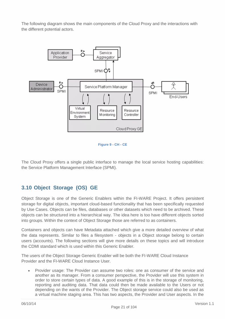
The following diagram shows the main components of the Cloud Proxy and the interactions with
the different potential actors.
Figure 9 - CH - CE
The Cloud Proxy offers a single public interface to manage the local service hosting capabilities:
the Service Platform Management Interface (SPMI).
3.10 Object Storage (OS) GE
Object Storage is one of the Generic Enablers within the FI-WARE Project. It offers persistent
storage for digital objects, important cloud-based functionality that has been specifically requested
by Use Cases. Objects can be files, databases or other datasets which need to be archived. These
objects can be structured into a hierarchical way. The idea here is too have different objects sorted
into groups. Within the context of Object Storage those are referred to as containers.
Containers and objects can have Metadata attached which give a more detailed overview of what
the data represents. Similar to files a filesystem - objects in a Object storage belong to certain
users (accounts). The following sections will give more details on these topics and will introduce
the CDMI standard which is used within this Generic Enabler.
The users of the Object Storage Generic Enabler will be both the FI-WARE Cloud Instance
Provider and the FI-WARE Cloud Instance User.
Provider usage: The Provider can assume two roles: one as consumer of the service and another as its manager. From a consumer perspective, the Provider will use this system in order to store certain types of data. A good example of this is in the storage of monitoring, reporting and auditing data. That data could then be made available to the Users or not depending on the wants of the Provider. The Object storage service could also be used as a virtual machine staging area. This has two aspects, the Provider and User aspects. In the

06/10/14 Page 22 of 104
Version 1.1
case of the Provider, a User will upload a virtual machine image to the object storage service and once received, the Provider will make this virtual machine image available for instantiation in order to satisfy a particular customized virtual machine request (the case here is that the virtual machine images that the Provider offers are not sufficient and the User wishes to supply their own). From a management perspective, the Provider will expect that the system will require as little maintenance as is possible. This entails that any:
o stale data be purged,
o deactivated accounts be removed,
o corrupt data is replaced with a valid replica,
o Issues are escalated to an automated service that will attempt to resolve them (if they cannot be resolved then notifications to the Provider should be sent),
o relevant statistics should be available to support inspection of the system and the User's utilization of the system,
o additional requirements for hardware (storage capability) can be easily added to the system without any drop in service. This will allow the storage capacity to grow over time.
User usage: The User will use the object storage service as a means to distribute static content rather than incur the additional load of serving static content from an application. Taking this approach allows the Provider to optimize the distribution of those files. The Provider can also use this as a building block to offer further content distribution network capabilities. The User could also use the object storage service as a means to supply a customized virtual machine that only they have access to (the storage is isolated by user). This would follow in a similar fashion to how customized virtual machine images are supplied on Amazon EC2.
The Object Storage GE adopts the Cloud Data Management Interface (CDMI) specification.
Figure 10 - CDMI
At the core of CDMI are the basic management operations of Create, Retrieve, Update and Delete.
This functionality is exposed via a RESTful API that:
Enables clients to discover capabilities of the object storage offering
Manage containers and the objects that are placed within them
06/10/14
Page 23 of 104 Version 1.1
Assigns and manipulates metadata to containers and objects
3.11 Data/Context Management Architecture
The Data/Context Management FI-WARE chapter aims at providing outperforming and platform-
like GEs that will ease development and provision of innovative Applications that require
management, processing and exploitation of context information as well as data streams in real-
time and at massive scale. Combined with enablers coming from the Apps Chapters, Application
Providers will be able to build innovative business models such as the ones described above and
beyond.
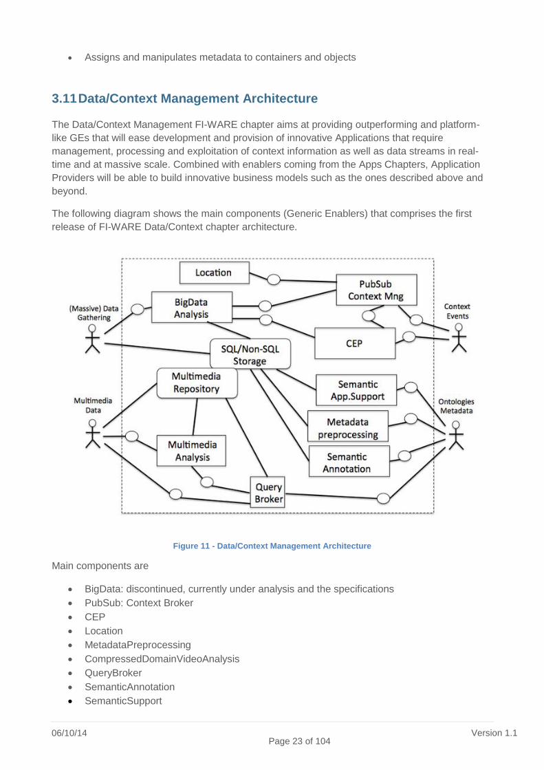
The following diagram shows the main components (Generic Enablers) that comprises the first
release of FI-WARE Data/Context chapter architecture.
Figure 11 - Data/Context Management Architecture
Main components are
BigData: discontinued, currently under analysis and the specifications
PubSub: Context Broker
CEP
Location
MetadataPreprocessing
CompressedDomainVideoAnalysis
QueryBroker
SemanticAnnotation
SemanticSupport

06/10/14 Page 24 of 104
Version 1.1
3.11.1 Context Broker (Publish/Subscribe Broker) GE
The Context Broker GE will enable publication of context information by entities, referred as
Context Producers, so that published context information becomes available to other entities,
referred as Context Consumers, which are interested in processing the published context
information. Applications or even other GEs in the FI-WARE platform may play the role of Context
Producers, Context Consumers or both. Events in FI-WARE based systems refers to something
that has happened, or is contemplated as having happened. As such, they provide context
information that can be handled by applications or FI-WARE GEs.
Figure 12 Content Broker visual presentation
3.11.2 Complex Event Processing (CEP)
CEP analyses event data in real-time, generates immediate insight and enables instant response
to changing conditions. Some functional requirements this technology addresses include event-
based routing, observation, monitoring and event correlation. The technology and implementations
of CEP provide means to expressively and flexibly define and maintain the event processing logic
of the application, and in runtime it is designed to meet all the functional and nonfunctional
requirements without taking a toll on the application performance, removing one issue from the
application developer’s and system managers concerns.

06/10/14
Page 25 of 104 Version 1.1
Figure 13 - Complex Event Process Logical Architecture
3.11.3 Location GE
The Location Platform provides location-based services for two types of users:
Third-party location clients
o Third-party location clients can interact with the location platform using the Mobile
Location Protocol (MLP) interface or RESTful Network API for Terminal Location
both standardized by Open Mobile Alliance (OMA).
o These interfaces facilitate many services to retrieve the position of a compatible
target mobile terminal for various types of applications, ranging from single shot
location retrieval to area event retrieval (geo-fencing).
o The target mobile terminal position is retrieved using Assisted Global Positioning
System (AGPS), WiFi and Cell-Id positioning technologies intelligently triggered
depending on end-user environment and location request content (age of location,
accuracy, etc.).
Mobile end-users
o When an end-user searches for its position using a compatible terminal via any kind
of application requiring location information, the terminal connects to the location
platform to exchange assistance data in order to compute or retrieve its position, as
negotiated between the terminal and the platform.
o Moreover, some applications on the compatible terminal may include the sharing of
location information with external third-parties, including other end-users.
o Such service relies on another OMA standard, called Secure User Plane (SUPL).

06/10/14 Page 26 of 104
Version 1.1
Figure 14 - Location Platform GE Logical Architecture
The following services are the grounds of the Location GE:
MLP service: made of an HTTP stack, it processes MLP compliant requests and after
authorization of such request, it triggers the SUPL service to establish communication with
the target handset (SMS) to retrieve location or events depending on the content of the
request. Such request is encoded in XML format fully specified in MLP standard.
NetAPI Terminal Location service: similar to MLP agent, it decodes HTTP requests using
RESTful procedures and once authenticated triggers the establishment of a SUPL
connection with the target handset (SMS) for similar services to MLP.
SUPL service: made of a TCP stack, this server is used both to establish communication
with a target handset (SMS) and receive connection from the handset. The SUPL service
implements SUPL standardized procedures based on ASN1. Such procedures include
single shot location retrieval and triggers used for periodic and area event tracking. Such
interface is also used to exchange GPS assistance data via the 3GPP RRLP protocol
encapsulated in the SUPL payload.
3.11.4 Metadata Preprocessing GE
Target users are all stakeholders that need to convert metadata formats or need to generate
objects (as instantiation of classes) that carry metadata information. The requirements to transform
metadata typically stem from the fact that in real life various components implementing different
metadata formats need to inter-work. However, typically products from different vendors are
plugged together. In this case, the Metadata Preprocessing GE acts as a mediator between the
various products.

06/10/14
Page 27 of 104 Version 1.1
Figure 15 - Metadata Preprocessing GE Logical Architecture
The functionality of the components is described in the followings.
Control Interface: The control interface is the entity for configuring and controlling the
metadata processing engine. The algorithms used for transformation and filtering as well as
the metadata source are configured(connected using the configureInstance method. Sinks
receiving the outbound streams are connected and disconnected via the addSink and
removeSink methods, respectively. More details on the APIs are described in the Section
"Main Interactions".
Metadata Interface (for inbound streams): Different interchange formats (such as the ones
for streaming or for file access) can be realized (i.e., configured or programmed into this
interface at a later stage). An example format is the Real-time Transport Protocol (RTP) as
standardized in RFC 3550. Different packetization formats for the contained payload data
(i.e., the metadata) depending on the application might be used.
Metadata Transformation: The Metadata Transformation component is the core component
of this Generic Enabler. Based on an XML Stylesheet Language for Transformations
(XSLT7) and a related stylesheet, the processing of the metadata is performed. In principle,
other kind of transformations (other than XSLT) can also be applied. The output of this step
is a new encapsulation/formatting of the metadata received. This could also be an
instantiation of a class (e.g., JAVA, C++, C#, etc.)
Metadata Filtering: Metadata Filtering is an optional step in the processing chain. The
filtering can be used, e.g., for thinning and aggregating the metadata, or simple fact 7 [XSLT] W3C / M. Kay (editor), "XSL Transformations (XSLT) Version 2.0", http://www.w3.org/TR/xslt20/,
Jan. 2007 .
06/10/14 Page 28 of 104
Version 1.1
generation (i.e., simple reasoning on the transformed metadata). Depending on the
configuration of the GE, filtering can happen before, after, or even during transformation.
Metadata Interface (for outbound streams): Through this interface, the transformed (and
possibly filtered) metadata or metadata stream is accessed.
3.11.5 Compressed Domain Video Analysis GE
The target users of the Compressed Domain Video Analysis GE are all applications that want to
extract meaningful information from video content and that need to automatically find
characteristics in video data. The GE can work for previously stored video data as well as for video
data streams (e.g., received from a camera in real time).
In the media era of the web, much content is user-generated (UGC) and spans over any possible
kind, from amateur to professional, nature, parties, etc. In such context, video content analysis can
provide several advantages for classifying content and later search, or to provide additional
information about the content itself.
Example applications in different industries addressed by this Generic Enabler are:
Telecom industry: Identify characteristics in video content recorded by single mobile users;
identify communalities in the recordings across several mobile users (e.g., within the same
cell).
Mobile users: (Semi-)automated annotation of recorded video content, point of interest
recognition and tourist information in augmented reality scenarios, social services (e.g.,
facial recognition).
IT companies: Automated processing of video content in databases.
Surveillance industry: Automated detection of relevant events (e.g., alarms, etc.).
Marketing industry: Object/brand recognition and sales information offered (shops near
user, similar products, etc.).

06/10/14
Page 29 of 104 Version 1.1
Figure 16 - Compressed Domain Video Analysis GE Logical Flow
A hybrid video coder can be divided in several generic components:
Coder Control: Controls all other components to fulfill pre-defined stream properties, like a
certain bit rate or quality. (Indicated by colored block corners)
Intra-Frame Encoder: This component usually performs a transform to the frequency
domain, followed by quantization and scaling of the transform coefficients.
Intra-Frame Decoder: To avoid a drift between encoder and decoder, the encoder includes
a decoder. Therefore, this component reverses the previous encoding step.
In-Loop Filter: This filter component could be a set of consecutive filters. The most common
filter operation here is deblocking.
Motion Estimator: Comparing blocks of the current frame with regions in previous and/or
subsequent frames permits modeling the motion between these frames.
Motion Compensator: According to the results of the Motion Estimator, this component
compensates the estimated motion by creating a predictor for the current block.
Intra-Frame Predictor: If the control decides to use intra-frame coding techniques, this
component creates a predictor for the current block by just using neighboring blocks of the
current frame.
Entropy Encoder: The information gathered during the encoding process is entropy
encoded in this component. Usually, a resource-efficient variable length coding technique
(e.g., CAVLC in H.264/AVC) or even an arithmetic coder (e.g., CABAC in H.264/AVC) is
used.
During the encoding process, the predicted video data p[x,y,k] (where x and y are the Cartesian
coordinates of the k-th sample, i.e., frame) gets subtracted from the raw video data r[x,y,k]. The
resulting prediction error signal e[x,y,k] then gets intra-frame and entropy encoded.
The decoder within the encoder sums up the en- and decoded error signal e'[x,y,k] and the
predicted video data p[x,y,k] to get the reconstructed video data r'[x,y,k]. These reconstructed

06/10/14 Page 30 of 104
Version 1.1
frames are stored in the Frame Buffer. During the motion compensation process, previous and/or
subsequent frames of the current frame ( r'[x,y,k+i], i ∈ ℤ \ {0} ) are extracted from the buffer.
3.11.6 Media-enhanced Query Broker GE
Multimedia data is produced at an immense rate. By investigating solutions and approaches for
storing and archiving the produced data, one rapidly ends up in a highly heterogeneous
environment of data stores. Usually, the involved domains feature individual sets of metadata
formats for describing content, technical or structural information of multimedia data [Stegmaier
09a]. Furthermore, depending on the management and retrieval requirements, these data sets are
accessible in different systems supporting a multiple set of retrieval models and query languages.
By summing up all these obstacles, easy and efficient access and retrieval across those system
borders is a very cumbersome task [Smith 08]. Standards are one way to introduce interoperability
among different peers. Recent developments and achievements in the domain of multimedia
retrieval concentrated on the establishment of a multimedia query language (MPEG Query Format
(MPQF)) [Döller 08a], standardized image retrieval (JPEG) and the heterogeneity problem
between metadata formats (JPEG) [Döller 10]. Another approach for interoperable media retrieval
is the introduction of a mediator or middleware system abstracting the communication: a Media-
enhanced Query Broker. Acting as middleware and mediator between multimedia clients and
retrieval systems, collaboration can be remarkably improved. A Media-enhanced Query Broker
accepts complex multi-part and multimodal queries from one or more clients and maps/distributes
those to multiple connected Multimedia Retrieval Systems (MMRS). Consequently, implementation
complexity is reduced at the client side as only one communication partner needs to be addressed.
Result aggregation and query distribution is also accommodated, further easing client
development. However, the actual retrieval process of the multimedia data is performed inside the
connected data stores.
Figure 17 - Query Broker : (a) Local/autonomous processing (b) Distributed processing

06/10/14
Page 31 of 104 Version 1.1
3.11.7 Semantic Annotation GE
The principle standing behind Semantic Web is to evolve the "link" concept from an unspecified
element describing the relationship between two element into a "named relationship" in order to
clarify which is(are) the relationship(s) between those elements.
That is the main reason why RDF, the language of Linked Open Data was invented. RDF is based
on Triples, in the form of<SUBJECT><PREDICATE><OBJECT>.
The predicate (and sometimes the object) can describe objects and their relationships. Semantic
Annotator is basically a tool which tries to identify important entities(places,persons,organization) a
text and describe them with Linked Open Data.
This GE provides a general purpose text analyzer to identify and disambiguate LOD (Linked Open
Data) resources related to the entities in the text. It is build following a modular approach to
optimize and distribute text processing & LOD sources (plug-in). Also it allows RDF triple
generation that easily links to LOD resources.
The main conceptual idea of the SA GE is shown in the Figure below.
Figure 18- Semantic Annotation GE Logical Flow
3.11.8 Semantic Support GE
The Semantic Web Application Support enabler aims at providing an effective environment for
developers to implement and deploy high quality Semantic Web-based applications. The Semantic
Web was first envisioned more than a decade ago by Tim Berners-Lee, as a way of turning the
Web into a set of resources understandable not only for humans, but also by machines (software
agents or programs), increasing its exploitation capabilities. The Semantic Web has focused the
efforts of many researchers, institutions and IT practitioners, and received a fair amount of

06/10/14 Page 32 of 104
Version 1.1
investment from European and other governmental bodies. As a result of these efforts, a large
amount of mark-up languages, techniques and applications, ranging from semantic search engines
to query answering system, have been developed. Nevertheless the adoption of Semantic Web
from the IT industry is still following a slow and painful process.
In recent years, several discussions had taken place to find out the reasons preventing Semantic
Web paradigm adoption. There is a general agreement that those reasons range from technical
(lack of infrastructure to meet industry requirements in terms of scalability, performance.
distribution, security, etc.) to engineering (not general uptake of methodologies, lack of best
practices and supporting tools), and finally commercial aspects (difficulties to penetrate in the
market, lack of understanding of the main strengths and weaknesses of the semantic technologies
by company managers, no good sales strategies, etc.).
The Semantic Application Support enabler addresses part of the abovementioned problems
(engineering and technical) from a data management point of view, by providing:
An infrastructure for metadata publishing, retrieving and subscription that meets industry
requirements like scalability, distribution and security. From now and so on, we will refer to
this infrastructure as SWAS Infrastructure.
A set of tools for infrastructure and data management, supporting most adopted
methodologies and best practices. From now and so on, we will refer to this tools as SWAS
Engineering Environment.
Figure 19 - SWAS-3: SWAS Infrastructure architecture
3.12 Internet of Things (IoT) Services Enablement Architecture
FI-WARE will build the relevant Generic Enablers for Internet of Things Service Enablement, in
order for things to become citizens of the Internet – available, searchable, accessible, and usable –

06/10/14
Page 33 of 104 Version 1.1
and for FI services to create value from real-world interaction enabled by the ubiquity of
heterogeneous and resource-constrained devices.
The deployment of the architecture of the IoT Service Enablement chapter is typically distributed
across a large number of Devices, several Gateways and the Backend. The Generic Enablers
described in this chapter, shown in the figure below, implement functionalities distributed across
IoT resources hosted by devices, IoT Gateways and in the IoT Backend.
Figure 20 - IoT Architecture
The architecture is composed of these elements:
Device and IoT Resource
o A device is a hardware entity, component or system that either measures properties
of a thing/group of things or influences the properties of a thing/group of things or
both measures/influences. Sensors and actuators are devices. Devices can further
be categorized into IoT compliant (i.e., devices with the full-blown FI-WARE
capabilities and supporting the standard ETSI M2M interface) and non-compliant
(legacy devices with propietary protocols).
o IoT Resources are computational elements (software) that provide the technical
means to perform sensing and/or actuation on the device. The resource is usually
hosted on the device.
Gateway

06/10/14 Page 34 of 104
Version 1.1
o A gateway is providing inter-networking and protocol conversion functionalities
between devices and the IoT backend. It is usually located at proximity of the
devices to be connected. An example of an IoT gateway is a home gateway that
may represent an aggregation point for all the sensors/actuators inside a smart
home. The IoT gateway will support all the IoT backend features, taking into
consideration the local constraints of gateway devices such as the available
computing, power, storage and energy consumption. Gateways are connected
northbound to the backend via IP connectivity and southbound to
IoT compliant devices without IP connectivity
Legacy devices that needs protocol conversion
o As IP devices will now appear on the market, the gateway will also be able to
manage some of them using IETF Core CoaP protocol but one of the main role of
the gateway is to bridge different technologies with IP connectivity. The second
main role is deployment of smart services as close as possible of the things to
enphazise smart applications development.
Backend
o The backend provides management functionalities for the devices and IoT domain-
specific support for the applications. It supports access at both IoT resource and
thing-level. The backend can be connected southbound to gateways and/or IoT
compliant devices (devices that will implement the standardised interface i.e. ETSI
M2M).
3.12.1 Backend IoT Broker GE
The IoT Broker GE is a component for retrieving and aggregating information from the Internet of
Things. The underlying data model of this GE is based on the OMA NGSI (Next Generation
Service Interface) Context Management Information Model, which is centered around on the
concept of context entities. Context entities represent arbitrary objects of the real world, and the
state of such objects is described in terms of the values of attributes. In addition, metadata can be
associated to attribute values. In the context of IoT, context entities are used for representing
devices like sensors and the values they measure, but also - and more importantly - arbitrary
physical objects (Things) like rooms, persons, etc. and their attributes like temperature, geo-
location, etc.

06/10/14
Page 35 of 104 Version 1.1
Figure 21 - Backend IoT Broker GE Logical Structure
The OMA NGSI context management interface distinguishes between two types of information.
This first type is so-called context information and consists of attribute values and associated
metadata as described above. This kind of information is exchanged using the operations defined
in OMA NGSI 10. The second type of information is information on where certain context
information can be retrieved by OMA NGSI 10 operations. This kind of information is referred to as
context availability information; it is exchanged using the operations defined in OMA NGSI 9.
3.12.2 Backend Discovery Engine GE
The IoT Discovery Engine (IoT-DE) GE addresses the discovery of Internet of Things (IoT)
Concepts. Its aim is to provide a platform for the semantic annotation and discovery of the IoT
Concepts defined in FIWARE, i.e. the Thing, Resource, and Device. It also provides semantic
annotation for Context Producers (e.g. IoT Agents, Service Endpoints) - or what is generically
termed as the 'Providing Application' in the current specification of the FIWARE NGSI Interface. In
contrast to NGSI, it aims to apply formal naming and relational conventions to the description of an
IoT Concept. The IoT-DE GE is built upon two modules. The first is the Sense2Web IoT Linked
Data Platform baseline asset, which provides a repository for the CRUD (Create, Read, Update
and Delete) management of IoT descriptions, that complies with the IoT-A ontology models. These
descriptions are termed as Advanced IoT Descriptions. Sense2Web also associates different IoT
concept ontologies to domain data and other resources on the Web. The second module is the
NGSI support module for the storage of NGSI Entities, whereby these Entities could hold a URI link
to the Advanced Description.

06/10/14 Page 36 of 104
Version 1.1
Figure 22 - Backend Discovery Engine GE Logical Architecture
This GE is targeted for:
Context Producers using IoT-A ontologies or NGSI9 Entity Description for IoT Description
CRUD management
o IoT Agents
o Device Gateways
Context Consumers using SPARQL or NGSI9 for discovering IoT Concepts.
o PubSub Broker GE (Data/Context Chapter)
o Applications requiring Semantic Discovery of IoT Concepts.
3.12.3 Backend Device Management GE
The Backend Device Management GE is the central component for the IoT backend. It provides
the resource-level management of remote assets (devices with sensors and/or actuators) as well
as core communication capabilities such as basic IP connectivity and management of
disconnected devices.

06/10/14
Page 37 of 104 Version 1.1
Figure 23 - Backend Device Management GE Interface overview
3.12.4 Gateway Device Management GE
The Gateway Device Management GE is contains much of the "core" gateway functionality. It is
responsible for the communication with the Backend and IoT and non-IoT devices. The Gateway
Device Management GE includes the functional components to handle the registration/connection
phases towards the Backend/Platform, to translate the incoming data or messages in an internal
format and to send the outgoing data or messages in the ETSI M2M format (marshall/unmarshall).
It is also capable of managing the communication with the IoT Resources, i.e. the devices
connected to the IoT Gateway (that may be online or offline), and resources hosted by the
gateway. The GE also contains Resource Management capabilities, i.e. to keep track of IoT
Resource descriptions that reflect those resources that are reachable via the gateway. These can
be both IoT Resources, or resources hosted by legacy devices that are exposed as abstracted IoT
Resources. In addition, any IoT resource that is hosted on the gateway itself if also managed by
this GE. The GE makes it possible to publish resources in the gateway, and also for the backend to
discover what resources are actually available from the gateway.

06/10/14 Page 38 of 104
Version 1.1
Figure 24 - Gateway Device Management GE Structure Overview
3.12.5 Gateway Data Handling GE
The IoT world mainly consists of a huge amount of resources, creating a lot of events to be
processed.
The Data Handling GE addresses the need of filtering, aggregating and merging data from different
sources; merging data is considered to be the main value-added feature. Applications should
receive value-added data that are relevant to their needs thanks to the Complex Event Processing
technology (CEP). This is also referred to as event stream analysis, or real time event correlation.
Events are published by Event Producers and subscribed to by Event Consumers. Events are
subscribed to by an event consuming application, depending on the access rights that have been
granted. The application is then able to receive published events.
The Data Handling GE can be configured either for mobile and fixed gateways or for constrained
environments. In the first case, its complex event processing core is based on Esper4FastData.
For constrained environments, as ‘light’ deployment can be chosen with SOL/CEP as the core for
the complex event processing.
Typical applications that require Data Handling GE are sensor network applications, RFID reading,
supply chains, scheduling and control of fabrication lines, air traffic and so on. What these
applications have in common is the requirement to process events (or messages) in real time or

06/10/14
Page 39 of 104 Version 1.1
near real time. Key considerations for these types of applications are throughput, latency and the
complexity of the logic required. The CEP component of the Data Handling GE typically processes
input data in order to generate a smaller set of output data that avoids backend and network
flooding.
The Data Handling GE also provides support for IoT hosting devices that for various reasons
cannot be continuously online. The main reason is that the devices work under resource
constraints such as being battery operated. This typically requires asynchronous communication
with the IoT resources and for this purpose, local storage is required. To this aim, the Local
Storage component provides two support functions. The first is to store cached IoT resource
requests from the backend that cannot be processed due to the relevant IoT device being off-line.
The second is to locally store retrieved data from IoT resources for subsequent retrieval by the
backend and ultimately the applications.
It is essential to handle the data and events from the IoT Resources (i.e. the devices connected to
the IoT Gateway) or from the Backend/Platform (i.e. the IoT Services Enablement Platform) in a
store. In particular the Data Handling GE deals with the Things Management GE events that are
propagated from and to the Backend/Platform. It also deals with the Gateway Device Management
GE events that are propagated from and to the IoT Resources. For that purpose, the Data Pooling
component provides functionality to discover what is stored in the data store, to retrieve, to create,
to delete, to update the data and events of the data store.
For privacy and security concerns, access and storage rights are defined at the closer level of data
production, to devices or to IoT resources. The Data Access Policy component is a dedicated
additional component to the Security, Privacy and Trust which is providing features for
authentication and centralized anonymization mechanisms.
The Data Handling GE comes in two configurations. One that supports anonymization, local data
support and another one that is aimed at constrained environments, which lack the resources for
storage or anonymization mechanism. Both are equipped with a Complex Event Processor, but
they are configured and operate in distinct ways. This distinction reflects the different resource
requirements of the hardware on which the Data Handling GE is deployed. The CEP provided by
Orange is aimed at a smart phone and the one by Atos is aimed at small, embedded sensor
gateways that can be installed at various points in a sensor network infrastructure, e.g. a Smart
City.

06/10/14 Page 40 of 104
Version 1.1
Figure 25 - Gateway Data Handling GE Interface Overview
3.12.6 Gateway Protocol Adapter GE
The Protocol Adapter GE deals with the incoming and outgoing traffic and messages between the
Gateway and Devices registered to be served by the gateway. There may be multiple instances of
Protocol Adapter GEs capable of serving non-IoT devices, i.e. devices that do not support ETSI
M2M. These devices can be IP-based devices, that communicates using the IP stack (IPv4 or
IPv6), or "legacy devices", meaning devices communicating using non-IP based protocols, for
instance ZigBee, or Z-Wave.
06/10/14
Page 41 of 104 Version 1.1
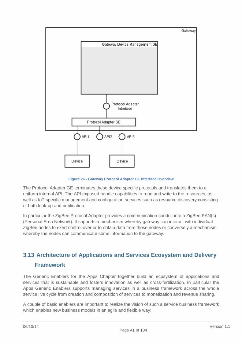
Figure 26 - Gateway Protocol Adapter GE Interface Overview
The Protocol Adapter GE terminates these device specific protocols and translates them to a
uniform internal API. The API exposed handle capabilities to read and write to the resources, as
well as IoT specific management and configuration services such as resource discovery consisting
of both look-up and publication.
In particular the ZigBee Protocol Adapter provides a communication conduit into a ZigBee PAN(s)
(Personal Area Network). It supports a mechanism whereby gateway can interact with individual
ZigBee nodes to exert control over or to obtain data from those nodes or conversely a mechanism
whereby the nodes can communicate some information to the gateway.
3.13 Architecture of Applications and Services Ecosystem and Delivery
Framework
The Generic Enablers for the Apps Chapter together build an ecosystem of applications and
services that is sustainable and fosters innovation as well as cross-fertilization. In particular the
Apps Generic Enablers supports managing services in a business framework across the whole
service live cycle from creation and composition of services to monetization and revenue sharing.
A couple of basic enablers are important to realize the vision of such a service business framework
which enables new business models in an agile and flexible way:

06/10/14 Page 42 of 104
Version 1.1
A Store, which allows to offer services for consumers as well as developers of future
internet applications.
A Marketplace, which allows to find and compare offerings from different stores and
provides further functionality to foster the market for future internet applications and
services in a specific domain.
An SLA Support, which monitors and evaluates runtime data according to the agreements
of service levels.
A Revenue Sharing System (RSS Engine), which allows the calculation and distribution of
revenues according to the agreed business models.
A set of Service Composition enablers, which allow to compose existing services to value
added composite services and applications, which can be monetized in the Business
Framework.
A set of Mediator enablers, which can be used to achieve interoperability between future
internet services and applications and also allow interface to existing enterprise systems.
This set of self-contained enablers represents only an initial starting point for a future business
framework. It is expected that supplemental enablers (e.g. for contracting, quotation ...) will be
developed outside of the FI-Ware projects.
The Business Framework is heavily relying on USDL as common uniform description format for
services which does not only focus on technical aspects of service, but also on business aspects
as well as functional and non-functional service attributes.. USDL itself is not a Generic Enabler,
since it is a data format and vocabulary specification. It will be introduced as an Open
Specification, which is used by different enablers in their provided and consumed APIs.
The Applications and Services Generic Enablers are named according to their main functionality
which is different from the role names introduced in the FI-Ware Vision. While the role names
(Aggregator, Broker, Gateway ...) are used to describe the stakeholders of the service ecosystem
in an abstract way, the enablers names are referring to software components.

06/10/14
Page 43 of 104 Version 1.1
Figure 27 - Services Ecosystem and Delivery Framework Logical Architecture
The chapter consists of
USDL is the Unified Service Description Language, which is used to share information
about services and apps between the different GE
Application Repository
Application Marketplace
Application Registry
Application RSS
Application Mediator
Application Store
Application Service Composition
Application Service Mashup
Application Mashup
Application Light-weighted Semantic-enabled Composition
3.14 USDL (Unified Service Description Language)
USDL (Unified Service Description Language) is a platform-neutral language for describing
services. USDL is building a layer on top of technical service descriptions such as WSDL, which
captures the information necessary to manage services in the business framework across the
whole service lifecycle.
Since USDL is just a data format and a set of vocabulary definition, we introduce it into FI-WARE
as an Open Specification. Because of the fundamental role for the business framework, we will
outline the rationale and concepts of USDL in this page as part of the architecture description of
the Application and Services Ecosystem chapter.
The FI-Ware approach will allow comprehensive service descriptions by employing the Unified
Service Description Language (USDL) in its registry and repository. USDL builds on standards for

06/10/14 Page 44 of 104
Version 1.1
the technical description of services, such as WSDL, but adds business and operational
information on top. With its ability to describe both human and IT-supported services that not only
implement business processes, but also tie in assets linked to contents and the Internet of Things,
USDL is set apart from many of the related approaches mentioned above.
Figure 28 - USDL (Unified Service Description Language) Entity Model
USDL is modularized to describe various aspects of services:
Foundational Module: This module provides a common set of concepts and properties,
such as time, location, organization, etc. that are used in all modules.
Service Module: Describes the general information about the service type, nature, titles,
taxonomy and descriptions.
Participant Module: This module describes the participating organizations, contact persons
and their role within the service fulfilment.
Functional Module: This module contains information about the specific capabilities of a
service, input/output parameters and constraints.
Interaction Module: A module that describes the points of interaction and the responsible
participants or participant roles in course of the service fulfilment.
Technical Module: Describes how functions (capabilities) of a service are mapped to
technical realizations of the service (e.g. WSDL operations, parameters, faults, etc.)
Pricing Module: Contains information about price plans, price components, fences, etc. for
a service.
Service Level Module: The module which specifies service level agreements, such as time
schedules, locations, and other constraints.

06/10/14
Page 45 of 104 Version 1.1
3.15 Security
The internet and digital technologies are transforming our society by driving economic growth,
reduces barriers to trade, connecting people across the world and providing new ways to
communicate and co-operate.
Our dependence on cyberspace is increasing and while cyberspace fosters open markets and
open societies, unfortunately this very openness can also make us more vulnerable to a growing
number of criminals, hackers, activists, foreign intelligence services, who want to exploit children
and the vulnerable, to harm individuals, enterprises, public and private organizations by
compromising or damaging revenues, reputations, privacy, business, critical infrastructures,
sensitive data…
Cyber criminals demonstrate their ability to adjust quickly to new developments like mobile phone,
“PlayStations”... The collective impact of this threat now has the potential to cause significant
damage to online economies, affecting individuals and societies.
For the first time in 2012, in its Global Risks 20212 report (Seventh Edition), the World Economic
Forum put cyber attacks fourth in the Top 5 Global Risks in terms of Likelihood (page 12). In this
report, we read (page 11 –“The Dark Side of Connectivity”): “ The impacts of crime, terrorism and
war in the virtual world have yet to equal that of the physical world, but there is fear that this could
change. Hyper connectivity is a reality. With over five billion mobile phones coupled with internet
connectivity and cloud-based applications, daily life is more vulnerable to cyber threats and digital
disruptions”.
Also Future Internet services will always be exposed to different types of threats that can lead to
severe misuse and damage. Creating secured and trusted services without sacrificing much of the
desired functionality, usability, performance and cost efficiency is a great challenge, especially in a
dynamic environment where new threats and attack methods emerge on a daily basis.
FI-WARE will provide an environment in which a diverse range of services are offered by a diverse
range of suppliers, and users are likely to unknowingly invoke underlying services in a more
dynamic and ad hoc manner. Moving from today’s static services, we will see service consumers
that transparently mix and match service components depending on service availability, quality,
price and security attributes. Consequently, the applications seen by the end-users may be
composed of multiple services emanating from many different providers, and the end user cannot
really know if the security solutions implemented by a service provider are compliant with security
policy claimed.
In this context it becomes essential to have means of security monitoring extremely efficient and
respond quickly to attacks. Of course, the Security monitoring covers more common threats, like
toll-fraud, impersonation, service high jacking etc. To defend ourselves, Future Internet services
need more intelligent early attack detection and support for decision and rapid action making faced
with constantly evolving threats. This is one of the challenges of FI-WARE.
The current landscapes of service delivery ecosystems do not fully address principals such as
openness, usability and simplicity. FI-WARE aims to balance between simplified service usage and
end user trust (including underlying security) in the service. FI-WARE will be designed in a flexible
manner in order to reflect generic as well individual requirements. By that FI-WARE will be easily
adaptable to upcoming needs. Furthermore this also is supported by including social interactions
being part of the working community, e.g. by offering a “security market place” where anyone
interested could contribute. A typical example of such a marketplace can be the sharing of

06/10/14 Page 46 of 104
Version 1.1
vulnerable configuration descriptions within a community of users, allowing faster reactions and
even prevention from potential attacks exploiting these vulnerabilities.
3.15.1 Architecture Overview
The overall ambition of the Security Architecture of FI-WARE is to demonstrate that the Vision of
an Internet that is "secure by design" is becoming reality. Based on achievements to date and/or to
come in the short-term (both from a technological but also a standardization perspective) we will
show that "secure by design" is possible for the most important core (basic) and shared (generic)
security functionalities as anticipated by the FI-WARE project and in accordance with the
requirements of external stakeholders and users. The “secure by design” concept will, therefore,
address both the security properties of the FI-WARE platform itself and the applications that will be
built on top of it. As such, the Security Architecture will focus on key security functionalities such as
identity management or security monitoring to be delivered as so-called generic security enablers
that will be integrated with the design and implementation of the FI-WARE.
Figure 29 - Overall FI-WARE Architecture Overview
Security, Privacy and Trust in FI-WARE is mainly focusing on delivering tools and techniques to
have the above-mentioned security needs properly met. Furthermore a decision making support
and the automation of countermeasures allow alleviating the workload of users and administrators
while raising their security awareness.
The high-level Reference Architecture sketched in Figure below is formed by four main modules:

06/10/14
Page 47 of 104 Version 1.1
1. Security monitoring,
2. Generic Security Services: Identity Management, Privacy, Data Handling,
3. Context-Based Security and Compliance,
4. Optional Generic Security Services: Secure Storage Service, Morphus antivirus, DB
Anonymiser.
These services will be instantiated at runtime.
3.16 Interface to Networks and Devices (I2ND) Architecture
I2ND defines an enabler space for providing Generic Enablers (GEs) to run an open and
standardised network infrastructure. The infrastructure will have to deal with highly sophisticated
terminals, as well as with highly sophisticated proxies, on one side, and with the network operator
infrastructure on the other side. This latter will be implemented by physical network nodes, which
typically are under direct control of an operator, or the node functionality will be virtualised – in this
case the I2ND functionality can be accessed by further potential providers, like virtual operators.
3.16.1 Architecture Overview
The I2ND architecture covers four Generic Enablers (GEs). The four GEs have interfaces and APIs
according to their underlying technologies:
CDI (Connected Device Interface) towards the Connected Devices. These devices include,
but are not limited to, mobile terminals, tablets, set top boxes and media phones, and have
features such as remote access from a control environment, exposure of own functionality
(device status, sensors, etc).
CE (Cloud Edge) towards the Cloud Proxies. Cloud Proxies are gateways, which connect
and control a set-up of nodes towards the Internet or/and an operator network. The nodes
might be either accessible or not accessible from the outside networks.
NETIC (NETwork Information and Control) towards Open Networks. Open Networks are
following the idea of flow based controlled networks, and can be used for virtualisation of
networks.
S3C (Service Capability, Connectivity and Control) towards Underlying Networks. The
underlying networks are following standards such as Next Generation Networks (NGNs) or
Next Generation Mobile Networks (NGMNs). In the case of the S3C specified in I2ND the
baseline underlying network is the Evolved Packet Core (EPC) by 3GPP.

06/10/14 Page 48 of 104
Version 1.1
Figure 30 - Interface to Networks and Devices (I2ND) Architecture
Each of the GEs of I2ND has specific interfaces towards Application Developers, Cloud Services,
FI-WARE and other Use Case GEs and projects. The respective interfaces are described in the
GE sections.
The GE S3C is the central point of the I2ND architecture. I2ND develops an enabling environment
which can be used by network operators. Together with NetIC, both GEs will build the environment
of an operator, which might even be a virtual operator. S3C can be seen as the GE to run and
steer the network infrastructure.
A special role in I2ND is devoted to the interface towards other operators. Since the Future Internet
infrastructure will follow the Internet philosophy of a multi domain/end-to-end path through different
network operators, it is necessary to interface with other operators. In I2ND the interface
description provided by the ETICS project is adopted. The interface between NetIC and other
operators promotes to the future of network interface virtualisation down to the network layer. This
interface might be restricted by the owner of the network infrastructure, thus offering a sub-set of
whole interactions.
The interfacing between S3C and CDI provides status and control information exchange of the
device and remote control capabilities. A respective interface template is used.
Cloud proxies might be part of an operator infrastructure. Therefore it is necessary to have access
to these network nodes through a standardised interface.
3.17 Developer Community and Tools Architecture
FI-WARE will provide various strategic and fundamental means enabling the development of

06/10/14
Page 49 of 104 Version 1.1
Future Intenet Applications (FIApp). It is expected that around FI-WARE a community of
developers will grown both to further work on the FI-WARE results (e.g. providing new Open
Specification or improve the existing ones, to code new GE implementation, or set-up new FI-
WARE Instances) and to develop new applications or doing business according to an open
paradigm.
3.17.1 Architecture Overview
The primary goal of the Developer Community and Tools (DCT) is to offer a multi-functional
development environment - FI-CoDE - enabling the development and management of the Future
Internet Applications (FIApp) built to address the needs of the Future Internet and based on the
adoption and integration of the Generic Enablers Implementations. The FI-CoDE Architecture
figure represents in a single diagram the main components provided to the Future Internet
developer.
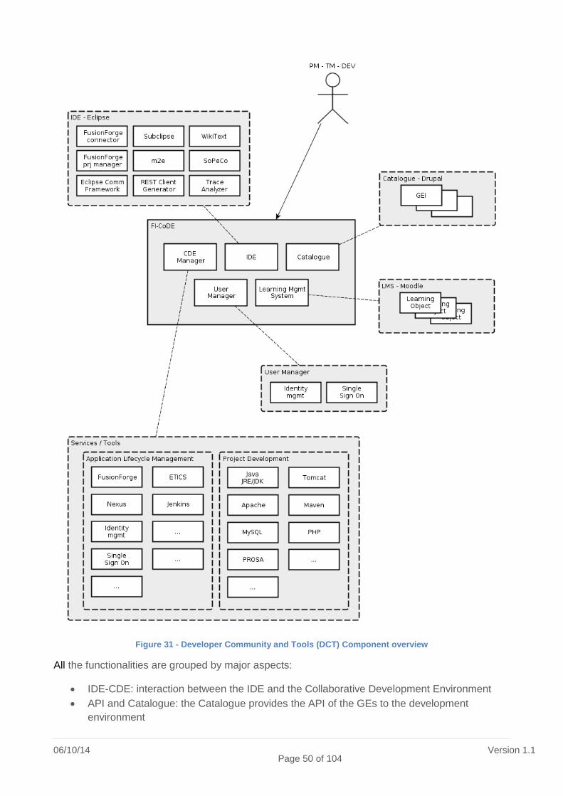
06/10/14 Page 50 of 104
Version 1.1
Figure 31 - Developer Community and Tools (DCT) Component overview
All the functionalities are grouped by major aspects:
IDE-CDE: interaction between the IDE and the Collaborative Development Environment
API and Catalogue: the Catalogue provides the API of the GEs to the development
environment

06/10/14
Page 51 of 104 Version 1.1
Deploy, Test and Validation: Future Internet Application deployment for testing and
validation activities.
For the first version of the FI-CoDE it has been decided to restrict the target development
environment to the Java language (version 1.6 and later). Additional languages will be added later
according to the available effort.
3.18 Outcome Analysis and Conclusions
FI-WARE is composed of Generic Enablers that are grouped in Chapters. The analysis of the
Chapter and their applicability to MOBiNET is presented in the table in the ANNEX. Beside the
single Chapter and GE, FI-WARE uses basic technology that can be adopted also without the full
adoption of the Generic Enabler. The table in ANNEX includes the analysis of some of these
technologies.

06/10/14 Page 52 of 104
Version 1.1
4 SPITS Project Architecture and outcomes
4.1 Introduction
SPITS8 is a Dutch collaborative project executed by its 13 partners and funded by the SPITS
partners and the Dutch Ministry of Economic affairs. SPITS is tasked with creating Intelligent
Traffic Systems (ITS) concepts that can improve mobility and safety. The SPITS project focuses on
three main areas: traffic management, in-vehicle solutions, and service download and
management solutions.
Intelligent Traffic Systems have the potential to utilize the existing road network more effectively as
well as increase its total throughput. Better information can also improve safety on the roads, for
instance when approaching sharp corners or alerting to other road users on imminent danger
ahead. The SPITS project is defining an open and scalable platform for future systems and
exploring new techniques in cooperative driving and mobility, to contribute to a more efficient and
sustainable mobility solution.
In the SPITS project, we examine an open and upgradeable in-vehicle platform on which these
systems could be deployed, to ensure the latest products can always be deployed over the lifetime
of the vehicle. The pace of modern innovation means that several technology generations are
released during the normal lifetime of a vehicle, so an upgradeable approach is essential to
keeping in-vehicle traffic systems relevant.
SPITS is exploring concepts to create a service download and management solution for in-vehicle
services that will cover consumer, fleet and traffic applications. In addition to hardware
upgradeability, the services that are run on these systems will also evolve, as will the information
they use. Adopting a simplified and open approach to services ensures that innovation and speed
can be increased, allowing exciting new services to be developed for the future of traffic
management and driver safety.
SPITS platform specifications should enable ITS and infotainment application designers to create
applications and services. An ITS or Infotainment software designer must be able to develop a
SPITS compliant application or service based on the information in these specifications. The
specifications define functions which can be used by applications.
The platform consists of three main components: a back office environment (BO), an in-vehicle
platform (OBU), and a road-side platform (RSU). Applications run on top of these three main
components. Throughout this document, aspects related to applications are indicated in green, to
the platform in yellow, and to sensors and actuators in purple.
8 Spits architecture group, Spits Architecture V1.1, 13-9-2011.

06/10/14
Page 53 of 104 Version 1.1
Figure 32 SPITS platform
4.2 Platform Architecture and Outcomes Description
4.2.1 SPITS platform context
The SPITS platform context view describes the relevant actors that interact with the platform. In the
context view the system is modeled as a black box. At the borders of the box 'Actors' are
connected through interfaces. Actors can be both man and machines. The main objective of the
context view is to make clear for whom the functionality of the system is meant to be. The
functionality itself will be defined through other Views.
The figure below shows the context view of the SPITS platform.
Figure 33: SPITS context view, showing the SPITS platform and the actors interacting with the platform.
Application Software is considered an external Actor to the platform. The Application User and
Administrative User use and manage the application software, respectively, indicated by the
dashed arrows. However, as will be made clear in the Scenario Views, they also interact with the
platform itself and are therefore included in the context view.
SPITS Application Software

06/10/14 Page 54 of 104
Version 1.1
SPITS Application software offers functionality/services to Application Users. Applications can be
based on the functionality offered by the SPITS platform and can be executed on the same
hardware used by the platform.
Application User
Application users are using SPITS compliant applications on the SPITS platform. Users can be
operators like traffic control, toll or parking operators, the driver, co-driver, passenger, fleet
managers, traffic center operator and others. Physical interaction of the Application User is via the
SPITS Platform (buttons, screen, speakers). Logically, the Application User interacts with SPITS
Application Software that receives the stimuli from and sends responses to the hardware of the
SPITS Platform.
Administrative User
This is a user that manages the SPITS applications, their configuration and settings. An
Administrative User typically is a provider of SPITS applications, and configures SPITS platform
related settings, e.g. for applications, users, devices, operational services. Owners are supported
to install new or remove old applications, and to (re)configure their devices. Owners are enabled as
Administrative Users to do system maintenance, such as user management, system management,
etc.
Maintainer
Person that develops, repairs, maintains, deploys, certifies and validates or queries software or
hardware modules in the SPITS Platform. The Maintainers interact directly with the SPITS
platform.
Vehicle
The vehicle provides sensory information from SPITS equipped vehicles of its surroundings and
own status to the SPITS platform and allows control by its actuators. This actor is described in
more detail in the OBU subsystem architecture.
Roadside device
Roadside devices are equipment along the road that are not part of the SPITS platform. This can
include legacy systems, like VRI's (traffic lights), VMS (text panels along the road), or loop
detectors. Roadside devices can be used by the SPITS platform to obtain information, or to
communicate with Drivers.
Non SPITS service
A service provided to the SPITS platform or Application software by a third party. For example:
Radio Broadcaster, GPS satellites and GPS signals, but also RWS (traffic management
center/service(s)).
4.2.2 System Scenario
The system scenario view describes a set of use case scenario's that are representative for the
use of the SPITS platform. The system scenarios have been divided in two sets: platform
scenarios and application scenarios. The application scenarios describe the use of Application
Software. Application software uses the platform to realize its functionality. In this way, the
Application scenarios also describe the (indirect) functionality of the platform. The platform
scenarios describe the direct interaction of actors with the platform. The figure below summarizes
both sets of scenarios.
The platform scenarios describe the scenarios related to the platform directly, i.e. not the
interaction of users with SPITS Application Software. An overview of all scenarios is given in the

06/10/14
Page 55 of 104 Version 1.1
figure below, and shows the interaction of the actors with these scenarios.
Figure 34: Overview of all platform scenarios.
The application scenarios describe the usage of applications that are running on top of the
platform. The majority of the applications are used by the Application User inside the Vehicle,
where the Application Software interacts, via the Platform with the Actor Vehicle (i.e. with the
sensors and actuators in the vehicle). Some of the applications (also) interact with roadside
equipment. The Application scenarios are further categorized loosely based on whether the
roadside equipment is involved (Road side supported scenarios) or only the vehicle (Vehicle based
scenarios) and a category of scenarios that does not fit either category (Other scenarios). The
figures below show these categories of scenarios and how they interact with each other and with
the actors.

06/10/14 Page 56 of 104
Version 1.1
Figure 35: Roadside device supported system scenarios.
Figure 36: Vehicle based system scenarios.

06/10/14
Page 57 of 104 Version 1.1
Figure 37: Other system scenarios.
4.2.3 System Design
The SPITS open and upgradeable platform ensures innovation can continue after first deployment.
Proven, industry standard architecture and interfaces increase speed of application, reduce cost,
and enable upgradeability. The SPITS architecture supports ITS applications by providing services
as communication, navigation, application and user-interface management, sensor virtualization,
and payment & billing. The SPITS platform consists of 3 types of subsystems: On-board Units
(OBU) built into vehicles, Road Side Units (RSU) monitoring and controlling road infrastructure,
and Back Offices (BOs) providing services to the other subsystems. Each subsystem has its own,
cost effective architecture optimized for its specific role. Together, they provide an application
platform for innovative traffic services that enhance mobility & safety. The subsystems are
designed to run (certified) applications developed by 3rd parties and enable new business models
for fast deployment.
Figure 38: The system design view of the SPITS platform, showing also all the Actors. The Actors that are connected to the platform can interact with all three individual subsystems.

06/10/14 Page 58 of 104
Version 1.1
4.2.3.1 The On-board Unit
The OBU subsystem is the SPITS subsystem which is inside a vehicle. It enables the execution of
SPITS applications on the On-board Unit. The OBU collects information from the vehicle sensors,
from other OBUs, from the BO, and from RSUs. The applications can use vehicle information and
communicate with the application user.
The main features of the OBU are:
1. The OBU support the possibility to add or remove functionality though a modular approach.
2. The OBU support the execution both of ITS and entertainment functionality on an single architecture.
3. The OBU can include optional services like navigation.
4. The OBU supports the possibility to add and remove temporarily (example: location specific) and permanent applications and platform related basic functions and services.
5. The OBU includes an HMI method dealing with safety related priority handling and variation of look and feel defined by vehicle manufacturers.
6. The OBU can communicate with nearby RSUs, nearby OBUs, BOs.
7. The functionality of the OBU can be managed remotely by a BO.
8. The OBU can be maintained locally by a system maintainer (e.g. a garage mechanic).
OBU concept
Today, the entertainment and navigation systems that are integrated in a vehicle have the same
life span as the vehicle. The development of these systems starts years ahead of the market
introduction of these vehicles, similar to other automotive vehicle systems. The functionality of
these systems remains similar to the functionality that was offered when the vehicle is bought,
which might be 10 years ago. In consumer (navigation) systems the time to market is shorter, the
innovation speed is higher, and the product prices are lower. The architecture described in this
document aims to bring these consumer benefits into the automotive entertainment, navigation,
and ITS systems.
Electrical perspective
Integrated entertainment, navigation, and ITS systems in a vehicle are typically connected to on-
board equipment. They are normally connected to on board speakers for audible entertainment,
hand free telephone calls, or spoken navigation instructions. They might be connected to vehicle
busses to obtain the vehicle speed, information from a steering wheel control, or the status of the
head lights (to adjust display colors at night). They might verify the vehicle’s identity to prevent that
a stolen system is used in another vehicle or they might interact with a tachograph in a truck.
These systems provide diagnostic functionality to vehicle service centers to aid vehicle repair. The
vehicle integration has mechanical, electrical, and communication protocols aspects. The
integration with the vehicle typically does not change over the life span of the vehicle as the vehicle
does not change.
In the architecture, the vehicle integration is separated from the other entertainment and navigation
functionality and they are decoupled. The vehicle integrated part offers standard mechanical and
electrically interfaces and communication protocols.

06/10/14
Page 59 of 104 Version 1.1
Figure 39: Example On-board Unit
Figure 39 shows an example entertainment and navigation system, called On-board Unit (OBU). At
the top elements are shown that are typically integrated for the vehicle’s life span. At the bottom
two kinds of elements are shown, nomadic devices (mass storage, iPod) and modules. Modules
are introduced as replaceable units used to allow faster in vehicle innovation, independent of the
vehicle integration. In the center of the figure is a head-unit, the head-unit is part of the vehicle and
it is the bridge between the modules and nomadic devices and the vehicle integration. The head
unit typically includes a graphical display.
To allow modules and nomadic devices to be added later, and to allow them to be exchanged
between vehicles, their interfaces should be agreed. The modules are connected via a standard
USB connection. This consumer bus is introduced in automotive to reduce the cost and increase
the flexibility, e.g. to interact with consumer devices. The modules can interact via standard USB
device classes with the head-unit. For example, a module can present itself as a USB camera to
send images to the head-unit’s display while retrieving user actions back via USB keyboard or
mouse messages. For more complex interaction, additional software interfaces are needed. For
example, interfaces to provide data for a unified HMI or interfaces to obtain wheel sensor or other
vehicle bus information. These software interfaces use USB as well. From functional point of view
USB is just a transport channel allowing addition and removal of nodes, from architectural point of
view some systems might also export a part of the functionality via another medium like Bluetooth.
For commercial applications of the On-board Unit, some modules might also be integrated in a
head-unit, limiting USB to the real plugable modules.
Figure 39 shows direct audio connections from a head-unit to the speakers, and a vehicle bus
between the head-unit and the wheel sensors. This is only an example; the head-unit’s physical
connections and peripherals will be vehicle model specific. Also the modules shown in the figure
might be included in a head-unit, for example in a high-end radio-navigation head-unit. A low cost
head-unit could rely on a module to offer such functionality. By supporting the module based
extension, the head-unit can be upgraded later when a new feature is developed that doesn’t fit
with the previous hardware generation.
Software perspective
An increasing amount of on board entertainment and navigation systems is equipped with wireless
connectivity. This enables value added services like finding an empty parking place, or informing a
vehicle on the access restriction for an area. These services typically need an off-board part to
provide the information and an on-board part to use the information or present it to the vehicle’s

06/10/14 Page 60 of 104
Version 1.1
driver. The off-board part could be done by a Road Side Unit (RSU) with local (traffic related)
information or a back office (BO) with location independent information. In addition to
communicating with an RSU and BO, the software might also use communication with On-board
Units of near-by vehicles.
The services will not only change in the life span of the vehicle, some will also change in the life
span of the modules. The set of 3rd party services offered for consumer devices in, for example,
Apple’s AppStore changes monthly. The software of the On-board Unit needs to be upgradeable
for the individual services that are offered. More specifically, upgrading is a service itself.
To allow software to be upgraded, the software interfaces available to the new software should be
known and also the context should be known. Some software might need a real-time guarantee,
other software might need a secure environment, and so on. This influences where the software
can be executed. Deployment of the software over the electrical modules or the head-unit depends
on these characteristics. In order to have commercial interesting systems, these contextual
constraints like the secure environment and real-time guarantee are not valid for each part of the
OBU. They are only valid in that part of the OBU which needs these constraints, e.g. a road-tolling-
module. For software without such constraints the software is be agnostic of where it’s executed or
which (wireless) communication channel is used.
Electrically the system can be extended with functional modules. If a module with a wireless
connection is added to a head-unit then it might replace or be used in addition to a wireless
connection from the head-unit. The same holds if a more advanced navigation module is added. In
general, 3rd party software on the On-board Unit does not care, if a hardware or software update is
done, it depends only on the software interfaces for the functionality it needs.
OBU SW deployment in SPITS
On the various OBU hardware parts various processing environments exist that can execute
software. An OBU head-unit can execute software and OBU modules can execute software. The
software on the head-unit and the modules might be upgradeable and one or more of them might
also support an OBU execution environment for SPITS applications.
Figure 40: Example SPITS application deployment
Figure 40 shows an example SPITS application deployed on a back office (BO), Road Side Unit

06/10/14
Page 61 of 104 Version 1.1
(RSU) and On-board Unit (OBU). Within the OBU this application is split into a head-unit part and a
module part. Whether or not a SPITS application requires a BO, RSU and OBU and how many of
those is application specific.
An example of a SPITS application could be a traffic management system where a central Back
Office application part provides a Road Side Unit with a requested traffic throughput to prevent
traffic jams. Based on this, the road-side application part determines a speed advice for a specific
vehicle and sends this advice to the On-board Unit on that vehicle. A module of the On-board Unit
runs an application to receive speed advices and the head-unit of the On-board Unit runs the user
interface to present this advice to the driver.
The deployment in the OBU is configuration specific. All application parts might run on a single
module or on the head-unit, or the different applications might be distributed. An OBU module
could be able to run SPITS application parts or it could come with software that has to run on
another node of the OBU in order to use the module. Figure 40 shows an example with two OBU
nodes capable of running SPITS OBU application parts and one module which does not. The latter
module might be a standard USB peripheral or module providing a wireless connection to Road
Side Units.
The application parts that run on a module or head-unit can use a SPITS OBU application
interface. This software interface offers functionality which could be located on the same module or
head-unit or on another one.
The OBU SW deployment section contains diagrams showing an application/platform interface for
the OBU. It shows that multiple interfaces exist. This section contains the interface definitions. The
OBU architecture distinguishes two types of interfaces: execution environment and SPITS
functions. The execution environment interfaces consist of the standard APIs that are provided by
the native and virtual operating environments.
Although the execution environment on an OBU can vary per module and head-unit, and different
execution environments can co-exist in parallel, the OBU has selected one execution environment
as its main execution environment; Linux/Android is used as main execution environment. Android
is selected because it offers a more cost efficient and commercially successful open software
ecosystem than the alternatives. It already offers a significant collection of applications and the
Android platform is open source.
The following figure provides an overview of the Android execution environment and the SPITS
extensions.
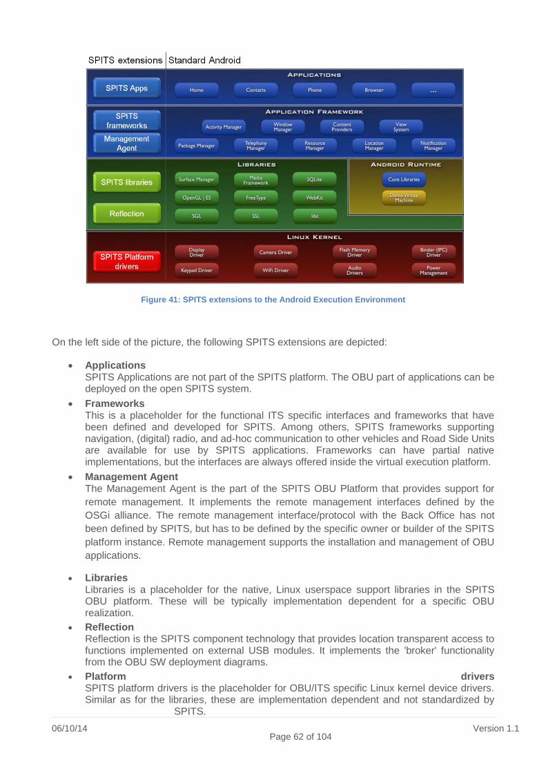
06/10/14 Page 62 of 104
Version 1.1
Figure 41: SPITS extensions to the Android Execution Environment
On the left side of the picture, the following SPITS extensions are depicted:
Applications SPITS Applications are not part of the SPITS platform. The OBU part of applications can be deployed on the open SPITS system.
Frameworks This is a placeholder for the functional ITS specific interfaces and frameworks that have been defined and developed for SPITS. Among others, SPITS frameworks supporting navigation, (digital) radio, and ad-hoc communication to other vehicles and Road Side Units are available for use by SPITS applications. Frameworks can have partial native implementations, but the interfaces are always offered inside the virtual execution platform.
Management Agent The Management Agent is the part of the SPITS OBU Platform that provides support for
remote management. It implements the remote management interfaces defined by the
OSGi alliance. The remote management interface/protocol with the Back Office has not
been defined by SPITS, but has to be defined by the specific owner or builder of the SPITS
platform instance. Remote management supports the installation and management of OBU
applications.
Libraries Libraries is a placeholder for the native, Linux userspace support libraries in the SPITS OBU platform. These will be typically implementation dependent for a specific OBU realization.
Reflection Reflection is the SPITS component technology that provides location transparent access to functions implemented on external USB modules. It implements the 'broker' functionality from the OBU SW deployment diagrams.
Platform drivers SPITS platform drivers is the placeholder for OBU/ITS specific Linux kernel device drivers. Similar as for the libraries, these are implementation dependent and not standardized by
SPITS.

06/10/14
Page 63 of 104 Version 1.1
4.2.3.2 The Road Side Unit
The RSU platform enables the execution of SPITS applications on the Road Side Unit.
Furthermore, the RSU enables the communication from OBUs to the BO and Non SPITS services.
The platform is maintained either remotely or locally by the Maintainer. The RSU collects
information from its Road Side Devices (camera's, loops, etc.), from Vehicles via their OBUs, from
the BO, and from neighboring RSUs. All information is made available to applications via
Information sources.
The main features of the RSU are:
1. The RSU can communicate with other RSUs, with the BOs, and with nearby OBUs.
2. The RSU enables the communication from the nearby OBUs to the BOs.
3. The RSU can be maintained locally or remotely by a Maintainer.
4. The RSU collects information from all kinds of sources (Road Side Devices, Non-SPITS services, OBUs) and makes this information available for Application on the RSU.
5. The RSU can communicate with the nearby OBUs, with the BO, and optionally with nearby RSUs.
The road side equipment plays an important role in ITS, and thus in the SPITS project. This
equipment has four main components or functions:
1. Sensors observing the roads, vehicles, and/or other environmental parameters, e.g. cameras, loop detectors, etc.
2. A communication node for (wireless) communication with vehicles.
3. A service platform for the execution of SPITS applications and platform services that are localized at the road side, e.g. for scalability or delay requirements.
4. The applications & services being executed on the platform.
In terms of the SPITS architecture and context (see RSU Context View), 1 is implemented by the
actor Road Side device, 2 and 3 by the Road Side Unit (RSU), and 4 by the RSU Application
software.
Figure 42: Functional decomposition of the RSU, including both the SPITS RSU platform and the RSU Application Software

06/10/14 Page 64 of 104
Version 1.1
RSU platform functions
OSGi Framework Part of the RSU Platform, responsible for providing class loading facilities, life
cycle management and for maintaining a (local) Service Registry. The OSGi framework is
represented as the System Bundle. The OSGi framework is the service platform on which RSU
Application Software can be deployed. SPITS uses OSGi Release 4, version 4.3. An important part
of the OSGi Framework is the support for IPv4 and IPv6, which is used for communication between
the RSU and the BO and optionally between the RSU and the OBU.
Standard OSGi Services These are standard functionalities that are part of the OSGi platform and
are standardized by the OSGi Alliance. All mandatory services are included. Other services are
optional, but if present, they should conform to the OSGi standards.
Communication Provider The communication provider is responsible for transmitting messages
to the vehicles and for receiving them. All incoming messages are collected and forwarded to the
appropriate Message Manager. Outgoing messages can be send to a specific region, specific
vehicle, or to all vehicles within range. For communication with OBU's CALM Fast over 802.11p is
supported.
Message Manager The message manager is responsible for encoding and decoding the
(standardized) messages, exchanged with vehicles via the ad-how wireless network. These
messages are partly standardized by ETSI, but for SPITS limited versions have been implemented.
CAM Message Handler This message handler is responsible for transmission of the RSU
Cooperative Awareness Messages (CAM), and for interpreting the incoming CAM messages from
the vehicles. The incoming messages are forwarded to the RSU Sensor Platform for fusion with
the road side information.
Dynamic Map The Dynamic Map provides a real time view on all vehicles in the area covered by
the RSU. The RSU Sensor Platform provides (asynchronous) information on the vehicles. The
dynamic map extrapolates this information and can provide a full view on request by an
application, or periodically.
Management Agent Part of the SPITS RSU Platform that provides support for remote
management. The interface with the OSGi environment is specified by the OSGi alliance. The
remote management interface/protocol with the Back Office has not been defined by SPITS, but
has to be defined by the specific owner or builder of the SPITS platform instance. Remote
management includes both the Installation process (install, update, remove applications) and
Execution management process (start, stop).
ITS Gateways The ITS Gateways provide the actual 802.11p based communication to vehicles,
i.e. the link to part of the Wireless Network (see Fig 5.1 in the SPITS Network architecture). Every
ITS gateway covers a defined geographical area. It still has to be decided how to define this area,
as exact boundaries for wireless communication cannot be specified. For cost and scalability
reasons, a single RSU platform can contain multiple ITS Gateways as further illustrated in the RSU
deployment section.
SPITS RSU Application Software and Road Side Device functions
The functions specified below are not part of the SPITS RSU platform. However, these functions
are using the SPITS Platform, or provide information to the SPITS platform.
RSU Sensor Platform The sensor platform provides real time information on the vehicles on the
road covered by the RSU. The information can be obtained from road side sensors (e.g. cameras),

06/10/14
Page 65 of 104 Version 1.1
or from vehicle information. The vehicle information is provided by the CAM Message handler and
forwarded to the RSU Sensor platform, where road side and car data is merged into a consistent
view on all vehicles. The link between the RSU Sensor Platform and the Dynamic Map follows the
Information Source design pattern as described in the system dataflow view Information Source.
Shockwave Damping Shockwaves occur on highly occupied roads when drivers react on
spontaneous maneuvers, resulting in a slow down or stopping of the traffic. The location where the
vehicles stop can move backward, causing a shockwave in the traffic flow. This application will
prevent or dissolves shockwaves by detecting when they arise and control the speed of the
vehicles.
Traffic Management This visualization application enables a traffic management center to have a
detailed view of the situation on the road.
Merging Assistant The merging assistant application detects gaps in the stream of vehicles on
the main road and advises merging vehicles on how to smoothly merge into this gap.

06/10/14 Page 66 of 104
Version 1.1
RSU Information source data flow
The picture below shows the data flow for Information Source related data. This means, that e.g.
the data flow towards the OBUs not is indicated in the figure below.
Figure 43: Data flow view of the Roadside equipment for Information source related data. Note, that additional data flows exist, e.g. for transmitting messages to the OBU's.
RSU deployment
As an example of RSU deployment, the SPITS Testsite Helmond is used. Below is a sketch of the
deployment view.

06/10/14
Page 67 of 104 Version 1.1
Figure 44: Implementation view of the Roadside equipment for Testsite Helmond9.
The cameras will be connected via fiber links to a central Ethernet switch. Also the ITS Gateways
are connected via this fiber network. The number of service platform devices for the test site is still
under discussion. An OSGi platform is not required on the ITS Gateways for SPITS application
software. However, it is still under consideration whether it is useful to implement an OSGi platform
for remote management functions on the ITS Gateways.
The Back Office
The BO enables the hosting of SPITS applications on the Back Office Unit. The BO is maintained
by local or remote System Maintenance. The main features of the BO are:
1. Infrastructure Management: Manages the SPITS network.
2. Application browsing, deployment of applications.
3. Services: Provides services by running service daemons.
4. Back-end: reporting, billing, portal to o the BOs and non SPITS services.
5. The BO can communicate with OBUs and RSUs.
4.2.4 Integrated Subsystem Design
The three subsystems are described in detail separately in their respective sections. The figure
below shows the interaction of the components of the subsystems.
9 Note, that the multiplicities are indicated correctly, but the absolute number of devices is not. The colors
correspond to the color usage in the previous figures.

06/10/14 Page 68 of 104
Version 1.1
Figure 45: Interaction of the 3 Subsystems
4.3 Outcome Analysis and Conclusions The SPITS architecture supports the same type of applications as MOBiNET. The Focus of the
SPITS architecture is mainly on the functionalities of the applications, whereas the focus of
MOBiNET is mainly on supporting the business interaction required to enable the applications. The

06/10/14
Page 69 of 104 Version 1.1
architecture is a good basis for the applications, to be supported by MOBiNET. The
implementations of the On board Unit can be used as a basis for the Mobiagent. The Roadside
Unit will be used on the DITCM Testsite in Helmond. Furthermore, the Service Platform of the
Roadside Unit can also be integrated in the mobiagent end-user devices.
06/10/14 Page 70 of 104
Version 1.1
5 Android and iOS eco-systems features
5.1 Introduction To be able to install MOBiNET apps on a wide variety of devices it is needed to have some
background information on how apps can be installed on these devices. For this we look at the 2
dominant mobile operating eco-systems: Android and iOS.
It is not intended to thoroughly describe the architecture of both eco-systems but to focus on the
features that a most relevant for MOBiNET. The following features will be focused upon:
• How apps are installed on a device
• How apps can detect other apps installed on a device
• How apps can communicate with other apps installed on the device
• How apps can unlock / install new features on the device
5.2 Platform Architecture and Outcomes Description
5.2.1 Installing apps
On an Android device
App developers are free to choose how they distribute apps to users. From publishing an app in a
market place to mailing an app directly to users, anything is possible10.
However users have to opt-in their device to be able to install apps from unknown sources. The
only known source for an Android device is the Google Play market place. Apps that are installed
from other sources than the Google Play market place will not be able to use Google Play's in-app
billing and licensing services.
The Google Play licensing service can be used to apply licensing policies on apps. For example an
app can restrict the use of the app to a specific device or to any other constrains a developer finds
appropriate 11.
To be able to reach the majority of Android users, and to be able to use Google Play services, the
Google Play market place is the best way to distribute apps.
The Google Play market place is available as a website and as a native Android app. From the
website it is possible to browse through the apps, purchase an app and have it installed on one of
your devices. The native Android app installs apps directly on the device itself.
10
https://developer.android.com/distribute/open.html 11
https://developer.android.com/google/play/licensing/index.html

06/10/14
Page 71 of 104 Version 1.1
It is possible to deep link directly to apps that are in the Google Play market place but Google does
not offer an official API to access the market place. However there are several unofficial libraries
that can be used to search the Google Play store and retrieve information meta-data of an app.
On an iOS device
The iOS App Store is the only way for iOS users to install apps on their devices (users willing to
jailbreak their device excluded 12). The App Store is available from within iTunes (available on both
Windows and OS X) and as a dedicated iOS app. It is possible to have an iOS device install
application purchased from within iTunes automatically but there is no way to push applications
towards a specific device, like there is in the Google Play market place website.
Apps that are purchased (paid or for free) and installed from the App Store are linked to the Apple
ID of the user. Apps are valid on all devices that are owned by the user for an unlimited time.
For websites and apps it is possible to deep link13 directly to apps that are in the App Store.
Clicking a link will select the app in iTunes, when used on a PC, or in the App Store app, when
used on an iOS device. iTunes has a search API14 than can be used by third parties to search the
App Store and retrieve information meta-data of an app.
5.2.2 How apps can detect other apps installed
On an Android device
Via the PackageManager API developers can retrieve information on all apps that are installed on
a device.
On an iOS device
On iOS there is no way to get a list of apps that are installed on the device. However under some
circumstances it is possible to check whether or not an app is present on the device.
iOS apps can support custom URL schemes that reference these apps. Other apps can check if
the custom URL scheme is supported on the device to see if an app is installed. There is a pitfall
though: if more than one app registers the same URL scheme there is no process to determine
which app is actually installed and will be started though the custom URL.
5.2.3 How apps can communicate with other apps
On an Android device
On Android, apps run in a sandboxed environment. There are different ways apps can
communicate with other apps (or processes). The first way is called Intents15. An app can send out
an Intent to do something. The Android OS looks for candidate to execute the Intent and sees that
12
http://cydia.saurik.com/ 13
http://linkmaker.itunes.apple.com/ 14
https://www.apple.com/itunes/affiliates/resources/documentation/itunes-store-web-service-search-api.html 15
https://developer.android.com/guide/components/intents-filters.html

06/10/14 Page 72 of 104
Version 1.1
an app that implements the Intent is started. When there are multiple candidates that implement an
Intent, the user is asked what apps to use. Arbitrary data, necessary to handle the Intent, can be
added to the Intent by the app that is sending the Intent.
Another way to interact with other apps is via a ContentProvider16. A content provider manages
access to a structured set of data and provides a mechanism to query and update that data.
Finally, it is possible to interact with another apps is through Services via either Android Interface
Definition Language17 or a Messenger18 depending if the service needs to perform concurrent inter-
process communication or not.
On an iOS device
On iOS, apps also run in a sandboxed environment. There is no equivalent of an Android Service
or Content Provider on iOS but there is something similar to the Intent mechanism. iOS devices
can communicate with other apps19 using custom URL schemas. An app creates a URL request,
using the custom URL schema, and adds arbitrary data to it. When the app opens the URL the
receiving app is moved to the foreground to open the URL and receive the data.
5.2.4 How apps can unlock / install new features
On an Android device
It is not mandatory that all executable code must be available in the app's binary distribution;
although downloading and adding executable code from within a running app is tricky20. Additional
features can be unlocked via Google Play in-app billing21 or another form of billing implemented by
the developer. Google Play's in-app billing can be used for one-time billing (standard in-app
products) and recurring, automated billing (subscriptions).
All in-app purchases made via Google Play on Android are consumables. If and how a consumable
is consumed is up to the developer. For example a premium upgrade of an app would typically not
implement product consumption.
On an iOS device
All executable code must be available in the app's binary distribution. Additional functions can be
unlocked via in-app purchases22. 3 different types of goods can be purchased via in-app
purchases: consumables, non-consumables and (auto-renewable) subscriptions.
Consumables can be bought more than once and can be used up. Non-consumables are bought
only once and are valid on all devices that are owned by the user. Subscriptions allow the user to 16
https://developer.android.com/guide/topics/providers/content-providers.html 17
https://developer.android.com/guide/components/aidl.html 18
https://developer.android.com/guide/components/bound-services.html#Messenger 19
https://developer.apple.com/library/ios/documentation/iPhone/Conceptual/iPhoneOSProgrammingGuide/AdvancedAppTricks/AdvancedAppTricks.html#//apple_ref/doc/uid/TP40007072-CH7-SW18 20
https://github.com/Rookery/AndroidDynamicLoader 21
https://developer.android.com/google/play/billing/index.html 22
https://developer.apple.com/library/ios/documentation/LanguagesUtilities/Conceptual/iTunesConnect_Guide/13_ManagingIn-AppPurchases/ManagingIn-AppPurchases.html#//apple_ref/doc/uid/TP40011225-CH4-SW1

06/10/14
Page 73 of 104 Version 1.1
purchase access to services or content for a set duration of time. Subscriptions renew
automatically unless the user opts out. Non-renewing subscriptions can also be offered.
Subscriptions must be available on all devices that are owned by the user.
The developer has to make sure that, when an in-app purchase is made, the feature that is
purchased by the user is unlocked and / or additional resources are downloaded from a server.
5.3 Outcome Analysis and Conclusions
From the analysis it becomes clear that both eco-systems behave somewhat similar on the
investigated features. Android gives the app developer the most flexibility in how to use the Google
Play services but all investigated features are also possible to implement, to a certain extent, on
iOS and the Apple App Store.
It will be possible to create a similar end-user experience for installing and using MOBiNET apps
on both platforms if the platform is willing to compromise on how MOBiNET apps interact with each
other.
Both the Google Play Store (see paragraph 4.5 of the distribution agreement and the Apple App
Store have a non-competition paragraph in their distribution agreements. This forbids the
distribution of apps whose purpose it is to distribute apps outside of the stores.

06/10/14 Page 74 of 104
Version 1.1
6 Instant Mobility Architecture and outcomes
6.1 Introduction
The Instant Mobility project was the Use Case project in the area of mobility of the Future Internet
Public-Private Partnerships (FI PPP) programme. The project defined scenarios and services for
multimodal travellers, drivers & passengers, passenger transport operators, goods vehicle
operator’s, road operators & traffic managers. A particular aspect of Instant Mobility was the
definition of requirements for Future Internet technology tools and enablers, so that all these
services will be available to any Internet-connected user, whether using a portable, vehicle-based
or fixed terminal.
In the Instant Mobility vision, every journey and every transport movement is part of a fully
connected and self-optimising ecosystem in which travellers, goods and collective transport will
benefit from personalised and real-time information delivered by next generation Internet
technologies. Future Internet technologies will offer accurate positioning, continuous connectivity
and a host of personalised online mobility services. The Instant Mobility project provided three
parallel scenarios for multimodal mobility for people and goods in urban areas with a user and
business-centred focus, namely: Personal travel companion; Smart city logistics; Transport
infrastructure as a service. Each scenario comprises a set of applications addressing the needs of
the different actors involved and describes a number of Future Internet-supported services that are
likely to be used by and to benefit a particular group of stakeholders. As the final output of Instant
Mobility, these scenarios have been demonstrated by conceptual software prototypes.
Instant Mobility and MOBiNET are quite complementary to each other. The focus of Instant Mobility
was to provide better mobility services on the basis of the Future Internet technologies. The focus
of MOBiNET is making the combination of existing mobility services easier by providing a minimum
set of infrastructure components. However, Instant Mobility offers good insights into the FI-WARE
GEs which are relevant to MOBiNET.
6.2 Platform Architecture and Outcomes Description
This section provides an overview about the Instant Mobility platform. We present Instant Mobility`s
leading use case scenarios, a high-level overview about the general platform architecture, and an
overview of the implemented prototypes.
6.2.1 Scenarios
6.2.1.1 Personal travel companion
The personal travel companion offers services for transport operators and human traveller`s to
provide and receive up-to-date information and to be guided in consequence. The scenario is
aimed at multi-modal travel, mainly in urban and inter-urban areas. Long distance journeys are
also taken into account but as a more straightforward case. Travellers, drivers and transport
operators will benefit from dynamic planning and follow-up during multimodal journeys:
Travellers will be able plan and adjust in real time a multi-modal journey from door to door;
Vehicle drivers will be able to easily book and execute ride sharing on their way to their own

06/10/14
Page 75 of 104 Version 1.1
destination;
Transport operators will get the complete information necessary to initiate demand driven
transportation.
The foreseen services are:
Dynamic multi-modal journey;
Dynamic ride sharing;
Optimized public transport usage.
6.2.1.2 Smart city logistics
Smart city logistics are aimed improving city logistics operations with respect to safety, efficiency,
environmental performance, and quality of service. It considers pick-up and distribution operations
mainly relying on the use of trucks or delivery vans. The smart city logistics scenario considers the
optimising of vehicle utilization, increasing consignee convenience by for instance flexible good
drop off and eco-optimised driving.
The foreseen services are:
Load sharing and optimising;
Dynamic time/place drop point;
Itinerary booking and real-time optimized route navigation;
Eco-optimised driving, vehicle and driveline control.
6.2.1.3 Transport infrastructure as a service
The transport infrastructure as a service provides online traffic and infrastructure management.
Dynamic traffic management and integrated urban space management will be virtualized and
based on Future Internet technologies such as cloud data storage, cloud computing and
virtualization or services‐ in‐ the‐ cloud. Transport infrastructure as a service defines the online
traffic and urban management generic enablers to improve the levels of mobility on the roads by
acting as B2B services (e.g., provision of accurate real-time traffic information for mobility services
such as routing information).
The foreseen services contain both information collection and service provision:
Real-time traffic and route information;
Floating passenger data collection;
Virtualized intersection intelligence;
Cooperative traffic signal control;
Area wide optimization strategies.
6.2.2 Platform Architecture

06/10/14 Page 76 of 104
Version 1.1
6.2.2.1 Architectural Vision
From a technical point of view the vision of the Instant Mobility platform is described best by the
following properties:
Data-centric:
Within the Instant Mobility system a continuous stream of data and events has to be
processed in an efficient and safe manner. The data originates from various origins like
travellers, floating cars, the road network or public transport officials.
Real-time:
Data and events have to be processed in real-time. E.g., this is an important system
property for the navigation and routing applications. Another example is the traffic operator
who needs to be immediately informed about critical traffic situations to undertake concrete
compensation actions. In this context, the term “real-time” means that the usefulness of a
result degrades after a deadline is missed. This is also referred to as “soft real-time” in the
area of real-time computing.
Distributed:
Not only processing nodes of the system are distributed over the network to create a robust
and scalable system. In addition, the data producers (like road side units, floating cars) and
the potential service consumers (like travellers) are distributed over the network as well. In
this context, a number of different nomadic devices like in-vehicle systems or mobile
phones are part of the system as well. They might act as both data producers and
consumers. Thus, the Instant Mobility system can be considered as a “heavily” distributed
mobile system.
Open:
The Instant Mobility services have to be provided using open, common, widely-used
standards to facilitate usage of the platform. In addition, this is required for efficient and
easy integration with external systems.
Federated:
The provided functionalities of the different scenarios focus on metropolitan areas. This
also needs to be reflected by the system architecture to be able to meet the real-time
constraints. Particularly, this is required to achieve the geographically scalability of the
system. The basic idea is to deploy a metropolitan-specific set of Instant Mobility services
on a “metropolitan-near” located cloud infrastructure. Thus, it is ensured that data is
efficiently processed next to its production.
Figure 46 summaries the basic assumptions and shows a high-level view of a metropolitan-specific
Instant Mobility instance.

06/10/14
Page 77 of 104 Version 1.1
Figure 46: High-Level View on the Instant Mobility System
Basically, the functionalities of the Instant Mobility ecosystem are offered by a RESTful
(Representational State Transfer) Web Service interface layer. These services form the basis to
build the scenario-specific applications of the different scenarios (e.g., Web portals, mobile
applications, etc.). For efficient distribution of data between data producers and data processing
components, an efficient real-time enabled data distribution middleware is required. However,
these systems introduce a relative tight coupling between components with regard to the
exchanged data. E.g., a major change of the data model could force a re-deployment of all
involved components. Thus, a complementary communication middleware system is required as
well which supports flexible, context-based publication of and subscription to data events. The
major use case is to provide context-aware information to external systems. This approach results
in a great flexibility when adaptions of the interaction patterns or the system architecture are
required. Finally, to achieve an elastic scalability of the overall system, the components run on a
cloud infrastructure.
Figure 47 sketches the idea of an Instant Mobility federated system.

06/10/14 Page 78 of 104
Version 1.1
Figure 47: Instant Mobility Federation
The basic idea is to deploy the required Instant Mobility components on a cloud infrastructure
which is located next to a metropolitan area. In particular, the different Instant Mobility clouds have
to be able to communicate, for instance, to transparently hand-over a traveller`s itinerary in case of
an inter-metropolitan journey. Another use case might be the quick dissemination of traffic events
which have the potential to sustainably influence the traffic situation in another metropolitan area.
6.2.2.2 Conceptual Architecture
Figure 48 shows the foreseen conceptual architecture of the Instant Mobility system. The following
sub-sections describe the specific layers of the multi-tiered architecture in more detail.

06/10/14
Page 79 of 104 Version 1.1
Figure 48: High-level conceptual architecture
6.2.2.2.1 Application Layer
The application layer contains the different end user applications and administrative user interfaces
which are developed in context of the specific scenarios. The basic idea is that the end user
applications are built on top of the API which is provided by the underlying service layer. For
instance, the traveller companion application calls the RESTful Web Service for planning a future
journey which is provided by the Multi-Modal Mobility sub-system.
The target platforms vary from scenario to scenario. Basically, the different scenarios require the
development of Web-based applications or applications which run on mobile devices or even on in-
vehicle devices.
6.2.2.2.2 Service Layer
The service layer exports the functionalities of service components in a standardized manner using
RESTful Web Services. Thus, it functions as the dedicated facade to the Instant Mobility
ecosystem. Primary, this layer provides the functionality which is used to implement the various
end user and management applications. In addition, it serves as an open, standardized integration
layer and entry point for third-parties like data providers. Additionally, the service layer allows the
re-use of the Instant Mobility functionality.

06/10/14 Page 80 of 104
Version 1.1
By applying the REST principles to the service layer, the service API is provided as a scalable
facade which is able to guarantee the same level of Quality of Service even with a largely
increasing number of client requests. In addition, REST provides the foundation to ensure
interoperability with a heterogeneous client environment and to safely evolve the service API.
6.2.2.2.3 Service Component Layer
This layer contains the server-side components, which implement the business logic of the Instant
Mobility ecosystem. Every component exposes its public API through RESTful Web Services.
Thus, the APIs of all components effectively build the service layer. Figure 48 shows the high-level
components of the different scenarios and example interactions.
Additionally, Figure 49 and
Table 1 provide a summary of the different subsystems and their dependencies.

06/10/14
Page 81 of 104 Version 1.1
Figure 49: High-Level overview of the Instant Mobility Subsystems
Table 1: Summary of identified subsystems
Subsystem Description
Multi-Modal Mobility
- Provides the core real-time navigation and routing functionality
- Covers aspects like multi-modal journey planning, itinerary
monitoring, and notification of travellers
Payment
- Provides services to include pricing offerings of different transport
providers
- Handles seamlessly all payment issues of the traveller by means
of virtual tickets
- Functions as a kind of payment broker to connect all involved
stakeholders
Personal Travel
Companion
- Provides the traveller`s front-end to plan and execute a multi-
modal journey
o Provides location-aware and situation-aware information to
the traveller
o Provides the traveller`s front-end to make use of the
payment services
- Focuses on seamless usage of all devices to achieve the best
possible journey experience
Public Transport
- Provides a front-end to enable public transport planners to
advertise their transport offerings and to operate and optimise
their offerings in accordance to the demand
Traffic Manager
- Enables a complete supervision of an area on the basis of
collected traffic information
- Implementation of “virtual” road side units
- Provides front-ends to different stakeholders for optimised
presentation of traffic information
Goods Transport - Supports sharing and optimisation of transport resources

06/10/14 Page 82 of 104
Version 1.1
Manager - Supports dynamic drop point negotiation between consignee and
haulier
- Enables the optimisation of transport itineraries on a basis of
transport mission and current traffic situation
6.2.2.2.4 Backend Layer
The backend layer separates the business logic from access to external system (e.g., for data
storage or information retrieval) by dedicated abstract interfaces.
From an analysis of the foreseen scenario-specific components, the following backend interface
types have been identified:
Data Storage and Backup:
Reliable data persistence is relevant for every scenario. In this context, statistical or
operational data has to be stored. However, there is also the need to process structured
and semi-structured data across the scenarios.
Real-time Traffic Data:
Traffic-related data is relevant for the scenarios “transport infrastructure as a service” and
“personal travel companion”. One shared requirement is that data events have to be
distributed to data processors in real-time as soon as they occur. In this context, collection
of location-based data and data originating from traffic infrastructure components is
required.
Traffic Control:
This interface enables a service component to interact and send commands to a traffic
infrastructure component like a road side unit or a traffic sign. Thus, it requires interaction
on a thing level. This interface is particularly relevant for the “transport infrastructure as a
service”.
6.2.2.2.5 Communication
Figure 50 sketches the foreseen communication architecture by showing the interactions between
selected components. Components are assigned to a specific architectural layer. Additionally,
communication flows, communication middleware components and provided interfaces are
illustrated.
In the following we summarise the foreseen communication options:
Point-to-point communication:
In this context, the involved components directly interact with each other in a synchronous
request-response manner. For that purpose the corresponding service components expose

06/10/14
Page 83 of 104 Version 1.1
specific RESTful Web Services.
An example is a request of the Transport Exchange Portal to the Multi-Modal Mobility
subsystem to provide alternative itineraries for transportation route optimisation. Another
example is the request of the Personal Traveller Companion application to plan a journey.
Context-based publish-subscribe communication:
This communication option supports flexible, context-based provision of data to the world of
final consumers (e.g., other platforms, components, end user applications). I.e., data
consumers can take into account the situation in which a specific data element has been
produced. This results in a great flexibility when adaptions of the interaction patterns are
required. The required middleware should be provided by the Context Broker GE23. The
Context Broker GE exposes a RESTful Web Service interface which can be used for
publication of context-aware data and to allow context-based subscription to data events.
An example is that the Personal Traveller Companion mobile application which only takes
specific itinerary events into account (e.g., changed route notification) while ignoring other
events (e.g., advertisement events).
Real-time, data-centric publish-subscribe communication:
This communication option supports real-time data sharing between data producer and
data consumer components. In this context, the data model should be quite mature (at best
following established standards) because major changes might require a re-deployment of
the involved components. In this context, the communicating components are required to
implement IDL-based interfaces which fit to the published data format. The required
middleware should be provided by the Advanced Middleware GE24. This GE addresses a
maximum level of system performance and scalability.
Real-time data sharing is particularly required by the data collection and data processing
components of the Multi-Modal Mobility and Traffic Manager subsystems. In this context,
formats of exchanged data are often compliant to established standards. Thus, we do not
expect major changes of resulting data models.
23
.http://forge.fi-ware.eu/plugins/mediawiki/wiki/fiware/index.php/ 24
.https://forge.fi-ware.eu/plugins/mediawiki/wiki/fiware/index.php/FIWARE

06/10/14 Page 84 of 104
Version 1.1
Figure 50: Communication Architecture
D31.1 -3.1 Platform state-of-the-art review
19/09/14 Page 85 of 104
Version 1.1
6.2.2.2.6 Security
Communication between components is basically performed on basis of RESTful Web Services which
utilise the HTTP protocol. Securing HTTP communication is well investigated topic. Thus, basically we
can rely on well-established authentication like TLS (Transport Layer Security). TLS is standardised by
the IETF25 and utilises different cryptography mechanisms in a flexible manner (e.g., asymmetric
cryptography for key exchange, symmetric encryption to ensure privacy, message authentication codes
to ensure message integrity). Thus, TLS provides secure point-to-point communication.
6.2.2.2.7 Federated Authentication
For authentication the use of federated authentication mechanisms rather than providing an own,
dedicated system is valuable. The OpenID 2.0 standard has been considered in order to provide a
federated authentication infrastructure and to enable single sign-on26.
6.2.2.2.8 Delegated Authorisation
As Instant Mobility provides a RESTful Web Service API, there are also use cases in which point-to-point
secured connection are not sufficient. Particularly, the user`s application might invoke a service which in-
turn needs to make another service call on behalf of the user. Thus, a mechanism for authorisation
delegation is required.
For RESTful APIs, OAuth 2.0 is the mean of choice and is already widely adopted. Instead of
transferring user credentials from one communication endpoint to another, a security token of restricted
lifetime is used to indicate that an application acts on behalf of the user.
OAuth introduces an authorisation server which is in charge of issuing security tokens and authenticating
end users. The application request the security token from the authorisation server and sends the
authorisation code for that purpose. For further technical details, we refer to DraftOAuthV227 and
OAuth2Introduction28.
6.2.2.2.9 Privacy
The collection of location information, both real-time locations and permanent locations (e.g., home
address), requires special considerations because:
The disclosure of this information might cause consequences for privacy and physical safety of
the user.
The simple transmission of a location may allow near-perfect personal tracking.
Location tracking can reveal a user`s home address and employer by looking for typical night and
day-time locations, even without identifying information.
Figure 51 shows the identified security data flow. The basic idea is to make use of pseudonym
certificates to establish the trust between the Instant Mobility services and the traveller. The pseudonym
certificate holds some verified attributes which allow services to make certain assertions about the
traveller but still hides his/her identity.
25
RFC524: http://tools.ietf.org/html/rfc5246 26
OpenIDWiki: http://wiki.openid.net/w/page/12995211/OpenID 27
DraftOAuthV2: http://tools.ietf.org/html/draft-ietf-oauth-v2-28 28
OAuth2Introduction: http://hueniverse.com/2010/05/introducing-oauth-2-0

06/10/14 Page 86 of 104
Version 1.1
TRAVELLER
POLICE
INSTANT MOBILITY
SERVICES PLATFORM
Pseudonym
Certicate
Request
(Step 1)
(Traveler)
Pseudonym
Certicate
(Step 2)
PAYMENT
AUTHORITY
(i.e. Bank)Payment Certicate
Request
(Step 3)
Payment
Certicate
(Step 4)
Multi-modal Transport
Request + Location +
Traveler preferences
+ (Traveler) Pseudonym
Certificate + (Traveler)
Payment Certificate (Step 5)
Roadmap
+ e_Ticket(s) + (Driver)
Pseudonym Certificate(s)
(Step 14)
PUBLIC
TRANSPORTATIONS
VPN
VPNRoutes and
Timetables
Request
(Step 6)
Routes and
Timetables
(Step 7)
Roadmap for
agreement
(Step 10)
Roadmap
agreement
(Step 11)
Buying e_tickets
with Payment
Certificate
(Step 12)
e_tickets
(Step 13)
K-A
nony
miz
atio
n & D
ata
Tran
sfer
Sensitive
Data base
Public Traffic
Optimization
Centre
DRIVER(s)
Traveller data
Drivers data,
Payment data.
Carpooling
Request
(Step 8)Carpooling
agreement
(Step 9)
Secure Ticketing Payment
Secure D
rivers Paym
ent with P
ayment C
ertificates
Security alert
Location + Driver
Identity + (Traveller)
Pseudonym Certificate
TRUSTED
AUTHORITY Identification RequestIdentification data
Traveller or Diver Pseudonym Certificate
Security alert
Traveller or Diver identityPolice Car
TRUSTED
AUTHORITY
Location + Traveler
Identity + (Driver)
Pseudonym
Certificate
(Traveler)
Pseudonym
Certicate
(Step 15) (Driver) Pseudonym Certicate
Pseudonym Certicate
Request
DRIVER
Location data (regularely) +
(Driver) Pseudonym Certificate
Figure 51: Security data flow
However, the “free” availability of fine-granular location information might still allow re-identification of
anonymised users.
For that purpose Instant Mobility requested the extension of FI-WARE`s current privacy concept by a
location monitoring component. This component should monitor the real-time location of anonymised
users. Particularly, it is the only component which obtains this kind of information. The user might
explicitly allow or disallow which events (e.g., planned itinerary delay, proximity alert) might be received
by whom. Thus, only authorised parties can subscribe to this information and are notified.
The component might also publish anonymised information about traveller`s movements. However, to
publish location data without compromising privacy, either a spatial-domain or a time-domain approach
has to be used. I.e., the traces are either
at coarse granularity levels so that the anonymity sets are large enough to preserve privacy (e.g.,
the location granularity is at city level or above) or
too short to make it difficult/impossible to infer locations correctly.
6.2.3 Overview of the implemented Prototypes
The following sections describe the developed prototypes. The description of every prototype includes
the implementation scope and an overview about integrated FI-WARE GEs.
6.2.3.1 Scenario 1 – Personal Travel Companion
Instant Mobility scenario 1 prototype simulates in a realistic way, the urban and suburban trips in a city,
based on the population's movement statistics. The city map displays the live positions of buses,
travellers and cars and the journey details of each traveller could be obtained in real time. A statistics

D31.1 -3.1 Platform state-of-the-art review
19/09/14 Page 87 of 104
Version 1.1
panel provides key figures of the simulation. The prototype also includes the dialog between a traveller
and a car driver involved in a common-ride.
Figure 52: Scenario 1 - Ride sharing prototype layout
6.2.3.1.1 Implementation Scope
The following figure shows the logical view of the multi-modal system main prototype.

06/10/14 Page 88 of 104
Version 1.1
Figure 53: Scenario 1 – Prototype logical architecture
As shown above, there are three core components:
Route Determination Engine:
This component provides itineraries for travellers and drivers (multi-modal solutions for travellers
and the fastest routes for drivers). Multi-modality requires to efficiently mixing multiple means of
transportation in a single consistent and optimal journey proposal. This component takes into
account all the means of transportation (private cars, buses, metro) in a consistent manner
making it easy to add new transportation modes.
Situation Display:
The situation display shows the position of travellers and mean of transportation. It calculates and
shows the mobility metrics (e.g. percentage of multi-modal itineraries). It allows for the selection
of the traveller/driver pair whose itinerary (and initial hand-shake dialog) can be shown on the
mobile phones. The display interface authorizes new events to be injected to the simulation (e.g.
car broken) leading to automatic rerouting of the potential travellers when required.
Simulator:
The simulator has multiple purposes. First, the simulation of the travellers/drivers by performing
itinerary requests to the route determination engines. These requests are based on the actual
statistical data of source-destination needs of the users. Second, the simulation moves the cars,
buses and other mean of transport taking into account historical flow speed at the time of travel.
The simulator is also responsible of the temporal coherence of the movements and of the

D31.1 -3.1 Platform state-of-the-art review
19/09/14 Page 89 of 104
Version 1.1
matchmaking between travellers and means of transport. Third, the simulator provides an
interface (REST) to the mobile applications to show itineraries of selected travellers (selection
being done by the situation display). The mobile applications (which include the on-board unit)
are pure Javascript implementations calling the simulator REST services.
The system uses an OMG (Object Management Group) Data Distribution Service middleware to achieve
linear scalability (application can scale by adding more processing units). There can be as many
instances of the core components as required. For example, the demonstration used four instances of
the “Route Determination Engine” all of them could be running on separate machines interconnected
through a local network.
All potential points of contentions have been identified and removed through data distribution,
aggregation and filtering (e.g. situation displays). One of the key benefits is that all components are
entirely decoupled. The application is fully distributed and most of the modules are pluggable.
Additionally, the Ride Sharing mobile application has been developed to show the possible user
experience. It was developed in HTML/CSS/Javascript and can thus be accessed by any standard web
browser. There are two users involved: a pedestrian (rider) looking for a ride and a driver that potentially
is able and willing to offer a ride. There is a single application which is thus twofold; the first splash
screen has the task to determine the user’s role.
Table 2 Ride Sharing mobile app
Initial Splash Screen
that allows to choose
between driver and
traveller interface
Here the user can
choose the start and
the destination (both
driver and rider case)
The system provides
an itinerary to the
rider. The itinerary
has a ride sharing
segment, indicated by
the multimodal icon in
the top-right corner of
the screen.
After clicking on
multimodal icon the
application asks the
rider if he wants to
accept the proposed
driver

06/10/14 Page 90 of 104
Version 1.1
If rider accepts, also
the driver is asked to
accept the proposed
rider.
When the driver
accepts the rider, the
system notifies it to
the driver and vice
versa
Here the two users
can see their
respective positions.
6.2.3.1.2 FI-WARE integration
The prototype integrates with the Data Handling GE29 to allow/disallow diffusion of travellers/drivers
pictures based on users predefined policies. If the Data Handling GE is disabled or if the policy does not
allow for picture diffusion, generic pictures (male or female) are shown on the traveller mobiles and on-
board units.
In addition, the prototype integration with Identity Management GE [22]30 that provides user management
capabilities has been tested (registration, login, etc.). A Java server that interacts with the Identity
Management GE has been developed, and now it’s ready to be integrated into the existing Personal
Traveller Companion server.
As the Advanced Middleware GE [16] was not ready at the time of the prototype implementation, the
OpenSplice Data Distribution middleware 31 has been used instead.
6.2.3.2 Scenario 2 – Smart City Logistics
The purpose of the “smart city logistics scenario” is to increase the sustainability of city logistics by
optimizing the vehicle utilization, in order not to use more vehicles than necessary and also to optimize
the way the vehicles are driven. A purpose specific to the “dynamic drop point” application, on which this
prototype is focused, is to increase the convenience for the consignee, by offering flexibility in choosing a
29
http://forge.fi-ware.org/plugins/mediawiki/wiki/fiware/index.php/Internet_of_Things_(IoT)_Services_Enablement#IoT_Data_handling 30
http://forge.fi-ware.eu/plugins/mediawiki/wiki/fiware/index.php/FIWARE.ArchitectureDescription.Identity_Management_Generic_Enabler 31
http://www.prismtech.com/opensplice

D31.1 -3.1 Platform state-of-the-art review
19/09/14 Page 91 of 104
Version 1.1
suitable time and location for dropping off goods, in order to avoid unnecessary transports, both by the
transporter, who can avoid trying to deliver goods to someone who is not at home, but also by the
consignee, who can avoid make an additional trip in order to pick up goods.
The pre-condition of the smart city logistics prototype is that a transport need has been detected and
transport resources have been registered in the system; that is, a set of transport bookings have been
submitted to the transport exchange portal via the Web service interface. Based on available transport
resources and submitted transport bookings, itineraries are planned by the system.
By using the Consignee App, the goods receiver can select calendar events to upload, which are then
used by the system as input when planning itineraries. Using the vehicle simulation web application,
itineraries can be downloaded to a simulated vehicle, which executes them on a map and reports back to
the transport exchange portal.
6.2.3.2.1 Implemented Scope
Figure 54: Smart City Logistics prototype architecture
The Smart City Logistics prototype consists of three main nodes; the vehicle, the server-side and the
consignee’s mobile device. The main components of the server side are the Web services, which
implement the vehicle transport management interface, the transport resource manager and the
consignee API. There are several clients to these Web services; the itinerary processor develops
itineraries based on the transport need and available resources, the transport exchange portal provides
an overview of the transport bookings and itineraries, the consignee app provides the dynamic drop point
service to the end user and the simulated vehicle executes the itineraries.
The simulated vehicle is a client to the vehicle transport management interface. It is implemented as a
Google Web Toolkit application running inside a Web browser, which lets the user select a vehicle
itinerary and follow the execution of the itinerary on a map.

06/10/14 Page 92 of 104
Version 1.1
The development activities performed to create this prototype consisted of both development of off-board
(server-side) and on-board (mobile) enablers, as well as creating a simulation of a freight vehicle,
performing the cargo distribution. This section lists the developed components.
Consignee App
The Consignee App is a smartphone app, developed for Android 4.0.x, which is used by the
consignee to share data on his/her whereabouts in order to agree with the transport planner
about a convenient time and location to receive goods. The consignee app first retrieves
transport booking information for transport bookings of which the consignee expects a
delivery. The consignee then selects the calendar events for which he/she is able to receive
the goods. These calendar events are then uploaded to the transport exchange portal. When
the calendar events have been processed a suggestion for a drop point is presented to the
consignee, who is then able to accept or reject it.
Remote Internet tethering
The remote Internet tethering enabler is composed by developments on an on-board unit
(having at least the function of IP router) and developments on smartphones. The objective of
this component in the context of logistic and/or goods transportation is to offer a wider range
of cellular connectivity to the on-board unit (OBU) by using opportunistically the cellular
network interfaces of smartphones (3G/4G) connected to the OBU.
Transport Exchange Portal
The Transport Exchange Portal functionalities developed for the prototype consist of a Web
portal for monitoring incoming transport bookings and transport missions, which are updated
in real time as they are being processed by the transport resources. The transport exchange
portal also consists of a number of other enablers, which implement the Web service interface
that the vehicle- and consignee applications use to interact with the system.
Vehicle Transport Management Interface
This is a RESTful Web service interface, implemented as a JAX-RS Web service. It contains
functions for retrieving transport itineraries, reporting status on a transport mission, reporting
current position and verifying the driver.
Transport Resource Manager
This is a RESTful Web service interface, implemented as a JAX-RS Web service. It contains
functions for creating, retrieving and deleting transport resources and for authenticating the
transport manager.
Consignee API
This is a RESTful Web service interface, implemented as a JAX-RS Web service. It contains

D31.1 -3.1 Platform state-of-the-art review
19/09/14 Page 93 of 104
Version 1.1
functions for authenticating the consignee, retrieving, creating and deleting calendar events,
retrieving drop points and accepting drop point suggestions.
Itinerary Processor
For the prototype a subset of itinerary processor functionalities was developed to cover the
functionality needed by the demonstration scenario.
Transport Resource Persistence
The transport resource persistence is implemented not as a separate component, but as a
part of the transport resource manager component, using the MongoDB Jackson mapper,
which provides seamless mapping between the JSON format used by the Web services, and
the BSON (binary JSON) format used internally by the MongoDB database.
Transport Booking Persistence
The transport resource persistence is implemented not as a separate component, but as a
part of the itinerary processor component, using the MongoDB Jackson mapper, which
provides seamless mapping between the JSON format used by the web services, and the
BSON (binary JSON) format used internally by the MongoDB database.
6.2.3.2.2 FI-WARE integration
The FI-WARE generic enablers were analysed in order to see how they could provide value to the
solution. The result of this analysis was that gaps was detected that must be addressed by FI-WARE
before the generic enablers can be incorporated in a meaningful way. The Identity Management only
supports SAML for API based authentication/authorization. SAML doesn’t however work with RESTful
web services, since it is dependent on a SOAP header for transferring the SAML messages.
The FI-WARE Big Data Analysis GE32 today consists of a map/reduce platform, which is a specialized
tool for tasks such as extracting information from large data streams, such as log files generated by
telecom systems. If the Big Data generic enablers are further developed to also include tools for
supporting other big data challenges, such as, for example, document oriented storage, it will be relevant
for a larger set of use cases, including the ones within smart city logistics.
6.2.3.3 Scenario 3 – Transport Infrastructure as a Service
In order to achieve efficient urban traffic management, cities need to deploy not only the technologies for
traffic monitoring, but also dedicated traffic management platforms, which can integrate all the data
coming from the different monitoring technologies so as to calculate and provide meaningful real time
information and strategies either for their own purpose as operators or for end users. All this has an
enormous cost for cities. Looking at it from an intersection control engineering, Traffic control in-the-
cloud is different from the existing approaches as traffic control operations will be hosted in the Internet,
32
http://forge.fi-ware.eu/plugins/mediawiki/wiki/fiware /index.php/Data/Context_Management#Big_Data_Analysis

06/10/14 Page 94 of 104
Version 1.1
leaving local systems the task of providing safety control and communications. At the intersections
absolute or selective prioritization policies can be applied, e.g. to give priority to special vehicles such as
buses, trams, emergency vehicles, commercial vehicles, etc. Furthermore, the system is able to
automatically detect critical traffic conditions and to activate dynamic green waves, to always keep the
network under equilibrium conditions.
According to the Traffic control in-the-cloud concept, Virtual road side units (V-RSUs) are hosted in the
cloud. These can apply different control strategies to control different systems and/or different sub-areas
of the same system. Different control strategies can be applied according to local needs, availability of
traffic measures and design options. Mainly, the system is fully adaptive on traffic and applies dynamic
optimisation concepts. The control strategies applied to the network are the result of an optimisation
problem aiming to minimise the overall time spent in the network by private traffic and public transport.
Real time optimisation and monitoring ensure an immediate reaction on traffic events. The overall
network optimisation is decomposed into co-ordinated junction problems solved by the virtual
intersection units. Each unit looks-ahead in the optimisation horizon in order to compute its own control
strategy in accordance with the upstream intersections.
Implementation Scope
The prototype is based on 10 V-RSUs (one for each intersection) installed in corresponding cloud VMs.
Since it is not possible to run tests on real roads, these have been substituted by a traffic simulator,
based on a microscopic approach to accurately represent the traffic conditions in the network. The used
microscopic simulator is a combined discrete continuous simulator. This means that there are some
elements of the system (vehicles, detectors) whose states change continuously over simulated time,
which is split into short fixed time intervals called simulation cycles or steps. There are other elements
(traffic signals, entrance points) whose states change discretely at specific points in simulation time. In
the simulation model the vehicles are generated and shipped through the network. This kind of approach
can be distinguished from other types of computer modelling in that it looks at the interaction of individual
"units" such as people or vehicles. Each vehicle is treated as an autonomous entity and the interaction of
the vehicles is allowed vary depending on stochastic (randomized) parameters. These parameters are
intended to represent individual preferences and tendencies. The area of the city involved in the
prototype will be comparable with a larger quarter of the city, and 10 intersections are included in the
simulator.
Each physical detector required by the V-RSUs has been modelled as one virtual detector. When a
vehicle is passing a detector message is generated towards the adaptive signalling which is treating the
incoming traffic information to set-up the best signal setting according to the present traffic situation. The
chosen strategy is shifted back towards the simulation model which is changing its signal according to
the adaptive strategy. It is important to underline that the abovementioned detectors have been used as
they represent the most consolidated way to realise communications between traffic simulators and
external controllers. According to the vision proposed by other “Transport Infrastructure as a Service”
Scenario applications, these detectors can be replaced from many other kinds of data coming either from
the infrastructure or from mobile devices, cooperative vehicles, and external providers.
Development activities have been focused on the traffic control functionalities, taking into account the
opportunities provided by cloud hosting. The component “Intersection virtual controller” is in charge of
creating the traffic signalling plans by computing the aggregated traffic information that receives from the

D31.1 -3.1 Platform state-of-the-art review
19/09/14 Page 95 of 104
Version 1.1
abovementioned components and systems. This component will enable the system to implement V-
RSUs, hosted in the cloud, in comfortable server farms.
cmp Intersection v irtual controller
Intersections v irtual controller
(from Traffic Manager)
«FI-WARE»
PaaS Management GE
Virtual Road-side Unit
Intersection controller
Diagnostic module
Traffic light gateway
Traffic l ight
vRSUs
V-RSUs gateway vRSUs
vRSUs
Queue estimator
Node balancerControl optimiser
Area-wide
Supervisor
Area-wide
Superv isor gateway Area-wide
Supervisor
PT priority optimiser
Cooperativ e
gateway OBU
Gateway
Figure 55: Intersections virtual controller components
As already introduced, the control strategies applied to the network are the result of an optimisation
problem aiming to minimise the overall time spent in the network by private traffic and public transport.
The optimisation is based on the continuous monitoring of the controlled network. Traffic flows are
measured every second and the intersection status is updated every three seconds. Real time
optimisation and monitoring ensure for an immediate reaction on traffic demand and events (incidents,
priority requests).
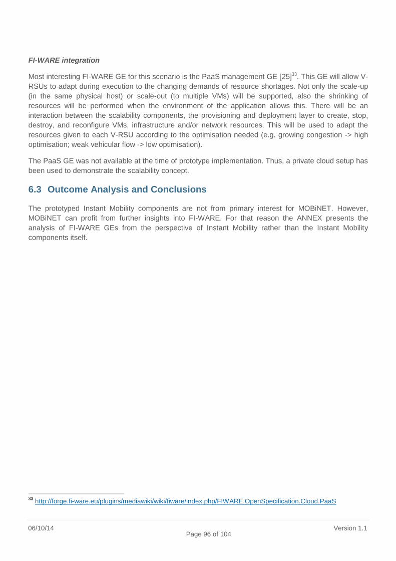
06/10/14 Page 96 of 104
Version 1.1
FI-WARE integration
Most interesting FI-WARE GE for this scenario is the PaaS management GE [25]33. This GE will allow V-
RSUs to adapt during execution to the changing demands of resource shortages. Not only the scale-up
(in the same physical host) or scale-out (to multiple VMs) will be supported, also the shrinking of
resources will be performed when the environment of the application allows this. There will be an
interaction between the scalability components, the provisioning and deployment layer to create, stop,
destroy, and reconfigure VMs, infrastructure and/or network resources. This will be used to adapt the
resources given to each V-RSU according to the optimisation needed (e.g. growing congestion -> high
optimisation; weak vehicular flow -> low optimisation).
The PaaS GE was not available at the time of prototype implementation. Thus, a private cloud setup has
been used to demonstrate the scalability concept.
6.3 Outcome Analysis and Conclusions
The prototyped Instant Mobility components are not from primary interest for MOBiNET. However,
MOBiNET can profit from further insights into FI-WARE. For that reason the ANNEX presents the
analysis of FI-WARE GEs from the perspective of Instant Mobility rather than the Instant Mobility
components itself.
33
http://forge.fi-ware.eu/plugins/mediawiki/wiki/fiware/index.php/FIWARE.OpenSpecification.Cloud.PaaS

D31.1 -3.1 Platform state-of-the-art review
19/09/14 Page 97 of 104
Version 1.1
ANNEX: Analysis Table
Project / Product Name
Outcome Name Outcome Description
Analysis of Applicability to MOBiNET
description of the outcome, what is consist of, what it does,
how the feature can be used in MOBiNET and why if is relevant to the project
FI-WARE Cloud Hosting (CH)
The Cloud Chapter offers Generic Enablers (GE) that comprise the foundation for designing a modern cloud hosting infrastructure that can be used to develop, deploy and manage Future Internet applications and services. The GEs in the above diagram are grouped into Core GEs, providing the core hosting capabilities at different abstraction levels (resources, services, objects, etc) and Ecosystem GEs, addressing various specific needs across the Core GEs, and establishing the ecosystem that enables the end-to-end capabilities provided by a cloud offering. The Core GEs include: - Data Center Resource Maangement (DCRM) GE - Object Storage GE - Service Management (SM) GE - Cloud Edge Resource Management GE - PaaS Management GE The Ecosystem GE is include: - Monitoring GE - Identity Management GE
The MOBiNET Platform can be hosted and uses CH services
FI-WARE
Open Cloud Computing Interface (OCCI)
The Open Cloud Computing Interface (OCCI) (TM) comprises a set of open community-lead specifications delivered through the Open Grid Forum, which define how infrastructure service providers can deliver their compute, data, and network resource offerings through a standardized interface. OCCI has a set of implementations that act as proofs of concept. It builds upon World Wide Web fundamentals by using the proven REST (Representational State Transfer) approach for interaction and delivers an extensible model for interacting with “as-a-Service” services.
The OCCI is used in the CH GE, the MOBiNET platform can use this way to describe the APIs.
FI-WARE
OpenStack Compute Developer Guide
OpenStack Compute Application Programming Interface (API) OpenStack can be used inside the MOBiNET platform

06/10/14 Page 98 of 104
Version 1.1
FI-WARE
Cloud Data Management Interface (CDMI™)
CDMI™ international standard is intended for application developers who are implementing or using cloud storage. CDMI is the de-facto standard for manipulating data in the cloud. Developed by the Storage Networking Industry Association (SNIA), it has now been designated by ISO as a formal international standard.
Inteface specification; basic technology
FI-WARE Data/Context Management (DCM)
The Data/Context Management FI-WARE chapter aims at providing outperforming and platform-like GEs that will ease development and provision of innovative Applications that require management, processing and exploitation of context information as well as data streams in real-time and at massive scale. Combined with enablers coming from the Apps Chapters, Application Providers will be able to build innovative business models such as the ones described above and beyond. The GE provided by Data/Context Chapter are: - Context Broker (Publish/Subscribe Broker) GE - Semantic Annotation GE - Complex Event Processing (CEP) GE - Location GE - MetadataPreprocessing GE QueryBroker GE Compressed Domain Video Analysis GE - Semantic Support GE
Applicability depends on the type of application that MOBiNET aim to develp/support
FI-WARE
Open Mobile Alliance (OMA) Next Generation Services Interface (NGSI) Specification
The Context Management APIs provides interfaces in order to • Manage the Context Information about Context Entities, for example the lifetime and quality of information. • Access (query, subscribe/notify) to the available Context Information about Context Entities. NGSI-9: Context Entity Discovery Interface NGSI-9 and NGSI-10 Interfaces with the following functions: • Register and retrieve the availability of Context Entities and/or Context Information. • Update Context Information in accordance to a specified Context Information Model. • Query for and subscribe to Context Information about Context Entities. NGSI-10: Context Information Interface
Interface specification for context Management
FI-WARE ContextML / ContextQL
ContextML: A Light-Weight Context Representation and Context Management Schema ContextQL or CQL is an XML-based language allowing to subscribe to the Context Broker (and in the future to Publish/Subscribe Broker) by scope conditions and rules consisting of more then one conditions.
Context Protocol

D31.1 -3.1 Platform state-of-the-art review
19/09/14 Page 99 of 104
Version 1.1
FI-WARE OMA/3GPP Specifications
MLP Mobile Location Protocol (MLP), Open Mobile Alliance, specification OMA-TS-MLP-V3_2-20110719-A SUPL Secure User Plane Location Protocol (SUPL), Open Mobile Alliance, specification OMA-TS-ULP-V2_0-20111222-D RRLP Radio Resource LCS Protocol (RRLP), 3GPP, specification 3GPP TS 44.031 V9.2.0 (2010-03)
Interface specification; basic technology
FI-WARE RTP RTP: A transport protocol for real-time applications Basic Technology
FI-WARE XSLT XSL Transformations (XSLT) Basic Technology
FI-WARE Internet of Things (IoT)
FI-WARE will build the relevant Generic Enablers for Internet of Things Service Enablement, in order for things to become citizens of the Internet – available, searchable, accessible, and usable – and for FI services to create value from real-world interaction enabled by the ubiquity of heterogeneous and resource-constrained devices. The GE implemented in the IoT Chapter are: - IoT Broker GE - Configuration Management GE - Discovery Engine GE - Device Management GE - Data Handling GE - Protocol Adapter GE
This chapter provides a middlware making information from heterogenous and large-scale Sensor/M2M deployments accessible via set of simple interfaces. Its applicability depends on the type of device that needs to be used in MOBiNET. Intresting for MOBiNET can be the Lookup and Discovery mechanisms.

06/10/14 Page 100 of 104
Version 1.1
FI-WARE
Applications and Services Ecosystem and Delivery Framework
The Generic Enablers for the Apps Chapter together build an ecosystem of applications and services that is sustainable and fosters innovation as well as cross-fertilization. In particular the Apps Generic Enablers supports managing services in a business framework across the whole service live cycle from creation and composition of services to monetization and revenue sharing. A couple of basic enablers are important to realize the vision of such a service business framework which enables new business models in an agile and flexible way: A Store, which allows to offer services for consumers as well as developers of future internet applications. A Marketplace, which allows to find and compare offerings from different stores and provides further functionality to foster the market for future internet applications and services in a specific domain. An SLA Support, which monitors and evaluates runtime data according to the agreements of service levels. A Revenue Sharing System (RSS Engine), which allows the calculation and distribution of revenues according to the agreed business models. A set of Service Composition enablers, which allow to compose existing services to value added composite services and applications, which can be monetized in the Business Framework. A set of Mediator enablers, which can be used to achieve interoperability between future internet services and applications and also allow to interface to existing enterprise systems.
This is the most relevant Chapter for MOBiNET. Relevant is USDL (Unified Service Description Language), see other entry
FI-WARE Security see main document This Chapter can be used for addressing security issues
FI-WARE
Interface to Networks and Devices (I2ND)
I2ND defines an enabler space for providing Generic Enablers (GEs) to run an open and standardised network infrastructure. The infrastructure will have to deal with highly sophisticated terminals, as well as with highly sophisticated proxies, on one side, and with the network operator infrastructure on the other side. This latter will be implemented by physical network nodes, which typically are under direct control of an operator, or the node functionality will be virtualised – in this case the I2ND functionality can be accessed by further potential providers, like virtual operators. The I2ND architecture covers four Generic Enablers (GEs). The four GEs have interfaces and APIs according to their underlying technologies: - CDI (Connected Device Interface) towards the Connected Devices. - CE (Cloud Edge) towards the Cloud Proxies. - NETIC (NETwork Information and Control) towards Open Networks - S3C (Service Capability, Connectivity and Control) towards Underlying Networks
This chapter deals with the interface of different network connection. The use depends on the connectivity requirements

D31.1 -3.1 Platform state-of-the-art review
19/09/14 Page 101 of 104
Version 1.1
FI-WARE Developer Community and Tools
FI-WARE will provide various strategic and fundamental means enabling the development of Future Intenet Applications (FIApp). It is expected that around FI-WARE a community of developers will grown both to further work on the FI-WARE results (e.g. providing new Open Specification or improve the existing ones, to code new GE implementation, or set-up new FI-WARE Instances) and to develop new applications or doing business according to an open paradigm. All the functionalities are described in detail in the subsequent chapters grouped by major aspects: IDE-CDE: interaction between the IDE and the Collaborative Development Environment API and Catalogue: the Catalogue provides the API of the GEs to the development environment Deploy, Test and Validation: Future Internet Application deployment for testing and validation activities.
The tools are based on Java programming language and may be used in case some part of the FI-WARE are used. Extension may also be considered
FI-WARE
USDL (Unified Service Description Language)
Unified Service Description Language (USDL), creates a “commercial envelope” around a service. More specifically, USDL allows a unified description of business, operational and technical aspects of services as depicted in the figure. Technical services may be lifted to business services, but USDL also allows describing more manual or physical services. As many services have a hybrid character with both, a digital and physical or manual footprint, USDL can facilitate the combination and aggregation of such services. Therefore, USDL can be considered one of the foundational technologies to set up an Internet of Services around today’s core enterprise systems.
Of high relevance to MOBiNET
Instant Mobility
Connected Device Interfacing GE
Basically, this GE provides a runtime for mobile applications. Additionally, CDI utilises different standards of the Open Mobile Alliance (OMA) [OMA] . The provided features include: • Mobile application runtime which provides a uniform interface to the nomadic device features. The current API is based on Web-based languages like HTML5, CSS3, and JavaScript. • The CDI GE, particularly, addresses the QoS and QoE aspects by provision of specific APIs. • Remote manager interface to support other external systems. It enables remote device management and allows sending data to the device via a push notification framework. • Mobility manager to select network interface in accordance to connectivity requirements of applications and to receive network policies. This GE has been considered as an Important building block to build mobile and in-vehicle applications for Instant Mobility.However, the GE was not available at the time of prototype implementation.
Of high relevance to MOBiNET. The GE could be used as basis for the MOBiNET Agent.

06/10/14 Page 102 of 104
Version 1.1
Instant Mobility
Applications and Services Ecosystem and Delivery Framework
FI-WARE uses Linked USDL to express the different aspects (technical, business, etc.) of services and to build a Internet of Services. Around this service description, FI-WARE provides the required infrastructure to facilitate service aggregation and re-use. The involved GEs (registry, repository, marketplace, composition engines, etc.) have been considered as an important building blocks to facilitate re-use of the Instant Mobility services. The GEs have not been integrated in any prototype because the focus of phase 1 was the creation of the required “backend” services.
Of high relevance to MOBiNET. USDL could be used to semantically describe the services. In addition, the provided USDL-enabled infrastructure components could be used as basis for the service directory.
Instant Mobility
Context Broker
The GE was planned to monitor traveler’s locations in order to get alerted in case of unexpected delays during the journey and of the proximity of point of interest. Unfortunately, it is not possible to plug-in your own listener handler to this pub/sub. The only kind of automatic notification we can build are based on interval values of latitude/longitude which is useless (we are interested to know if the traveler is on a specific road or at walking distance of a point of interest, not if its latitude/longitude are in specific ranges).
Publication of context information. Of low relevance to MOBiNET.
Instant Mobility
Advanced Middleware
It was planned to use this GE in the scenario 1 prototype to perform big data analysis and ensure scalability of the overall system. One particular advantage is its flexibility since it does not require processing to be independent (finding an itinerary solution modify the vehicle capacity and may invalidate concurrent solutions). As the GE is not included in the first FI-WARE, the corresponding scenario 1 prototype used a similar middleware (OpenSplice Data Distribution Service).
Flexible, scalable big data analysis. Of medium relevance to MOBiNET.
Instant Mobility
Object Storage
This GE was planned to be used in the scenario 1 prototype for storage of historical data (e.g., itineraries) into the cloud for later analysis. However, difficulties in accessing the corresponding testbed instance from a mobile station hindered its actual demonstration at the FI-PPP event in Barcelona.
Long-term storage of opaque data. Of medium relevance to MOBiNET.
Instant Mobility
PaaS
This GE is a key enabler for the scenario 3 prototype. It allows Virtual Road Side Units to adapt during execution to the changing demands of resource shortages. As the GE is not included in the first FI-WARE, the corresponding prototype used a private cloud setup.
Provision of an elastic scalable runtime environment for MOBiNET server-side components. Of high relevance to MOBiNET.
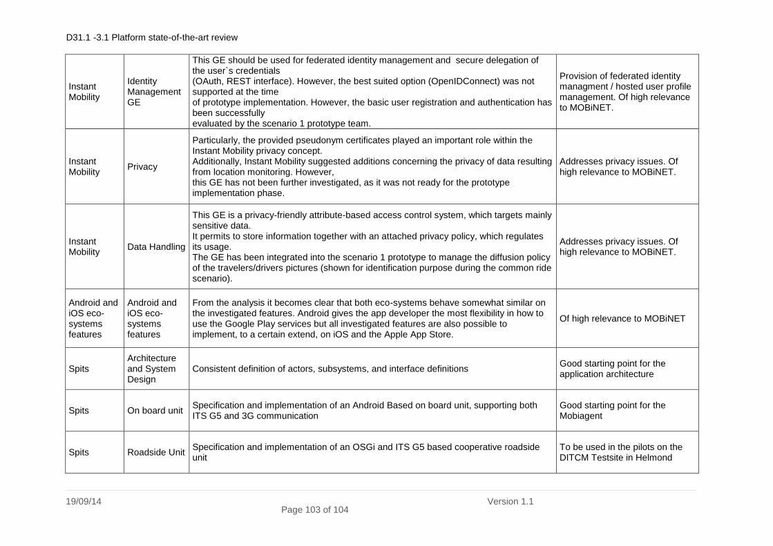
D31.1 -3.1 Platform state-of-the-art review
19/09/14 Page 103 of 104
Version 1.1
Instant Mobility
Identity Management GE
This GE should be used for federated identity management and secure delegation of the user`s credentials (OAuth, REST interface). However, the best suited option (OpenIDConnect) was not supported at the time of prototype implementation. However, the basic user registration and authentication has been successfully evaluated by the scenario 1 prototype team.
Provision of federated identity managment / hosted user profile management. Of high relevance to MOBiNET.
Instant Mobility
Privacy
Particularly, the provided pseudonym certificates played an important role within the Instant Mobility privacy concept. Additionally, Instant Mobility suggested additions concerning the privacy of data resulting from location monitoring. However, this GE has not been further investigated, as it was not ready for the prototype implementation phase.
Addresses privacy issues. Of high relevance to MOBiNET.
Instant Mobility
Data Handling
This GE is a privacy-friendly attribute-based access control system, which targets mainly sensitive data. It permits to store information together with an attached privacy policy, which regulates its usage. The GE has been integrated into the scenario 1 prototype to manage the diffusion policy of the travelers/drivers pictures (shown for identification purpose during the common ride scenario).
Addresses privacy issues. Of high relevance to MOBiNET.
Android and iOS eco-systems features
Android and iOS eco-systems features
From the analysis it becomes clear that both eco-systems behave somewhat similar on the investigated features. Android gives the app developer the most flexibility in how to use the Google Play services but all investigated features are also possible to implement, to a certain extend, on iOS and the Apple App Store.
Of high relevance to MOBiNET
Spits Architecture and System Design
Consistent definition of actors, subsystems, and interface definitions Good starting point for the application architecture
Spits On board unit Specification and implementation of an Android Based on board unit, supporting both ITS G5 and 3G communication
Good starting point for the Mobiagent
Spits Roadside Unit Specification and implementation of an OSGi and ITS G5 based cooperative roadside unit
To be used in the pilots on the DITCM Testsite in Helmond

06/10/14 Page 104 of 104
Version 1.1