d28ds - revision & intro to d28ds (vision)
DESCRIPTION
Analysis of Determinate Structures background notesTRANSCRIPT

School of the Built Environment
Course D28DS
Analysis of Determinate Structures
Dr Demitrios Cotsovos [Rm. 2.21 William Arrol Building]
Revision Lecture Forces, moments, stress and strain

School of the Built Environment
Course outline
• Revision: Forces, moments, stress & strain
Components of a force, combined action of forces, moments, equilibrium, free-body diagrams, determinacy in structures, stress, strain, linear-elastic behaviour, worked examples.
• Unit 1: Forces in Pin-Jointed Frames
Pin-jointed members, classification of trusses, statically determinate and indeterminate trusses, method of joints, method of sections, worked examples.

School of the Built Environment
Course outline
• Unit 2: Displacements in Pin-Jointed Frames
Causes of displacement, “work and energy” method, “unit load” method, effect of temperature, worked examples.
• Unit 3: Cable Structures
Examples of cable structures, single loads on a cable, multiple loads on a cable, cable shape under distributed loads, self weight, worked examples.

School of the Built Environment
Course outline
• Unit 4: Arches
Arch terminology, perfect arches, parabolic arches, eccentric thrust, arch collapse, tied arches, worked examples.
• Unit 5: Walls and Dams
Stability, line of thrust, overturning, factor of safety, sliding, worked examples.
• Unit 6: Internal Actions in Beams and Frames
Sign convention, beams carrying point loads, sketching deflected shapes, beams carrying distributed loads, cantilevers, applied moments, the relationship between shear and bending, beams with pins, quick method for beams, frames, torsion and three-dimensional structures, worked examples.

School of the Built Environment
Course Assessment
• Assessment made up of both examination and coursework (individual and group submissions):
- 70% Examination (2 hours – all questions to be attempted)
- 30% Coursework (Computer Coursework 10%, Solutions Portfolio 10%, Labs 10%)
• August resit – 100% examination.

School of the Built Environment
Performance in D28DS
• How you can maximise your chances of passing this course....
• Turn up and participate in all classes and tutorials.
• Ask questions!
• Submit your coursework on time.
• Don’t rely on learning methods “parrot fashion”, invest some time to try to understand them better.
• Pay a visit or two to the library – it’s there for a reason!

School of the Built Environment
Useful structures books
• There are a large number of textbooks that can help you better understand structures.....here’s a few examples:
• But there are plenty others to choose from in the library.

School of the Built Environment
Topics covered today
• Mass, force and weight.
• Resolution of components of a force.
• Calculation of combined action of forces.
• Free-body diagrams.
• Forces and moments in equilibrium.
• Statically determinate and indeterminate structures.
• Stress, strain, and linear-elastic behaviour.
• Displacements in axially loaded members.

School of the Built Environment
Mass, force and weight (1)
M
M F
M
g (= 9.81 m.s-2 on Earth)
acceleration a is also a vector
• Mass M is a scalar quantity – it has magnitude, but no direction:
– Units: g, kg, etc.
• Force F is a vector quantity – it has both magnitude and direction:
– Units: N, kN, etc.
• According to Newton’s second law:
Force F = mass M acceleration a
• Weight W is the force applied to a mass M due to gravitational acceleration g:
W = M g

School of the Built Environment
• As forces are vectors quantities they can be resolved into their horizontal and vertical components:
• Example: force resolution in 2 dimensions:
Direction Vertical Horizontal
Fy = -P Fx = 0
Fy = 0 Fx = -P
Fy =P sinθ Fx = P cosθ
x
y
x
y
Components of a force
θ
P
P
P
x
y

School of the Built Environment
Components of a force (2)
• The process is also reversible:
– knowing components of a force Fx and Fy , the magnitude and direction of force F can be calculated as follows:
• This process can also be used to consider components of a force in 3 dimensions:
– Fx , Fy , Fz F and
– Slightly more complex calculation for resultant force F (but same principle applies)
Fy
Fx
F
x
y
yx
F
F
FFF
1
22
tan
Fy Fz
Fx
F

School of the Built Environment
In-lecture question
• What are the vertical and horizontal components of force F = 10 N acting at θ = 30° to the horizontal?
Answer: Fx = F cos = 8.66 N
Fy = F sin = 5.0 N
• If the vertical and horizontal components of a force F are Fx = 2.5 N and Fy = 6 N, what is the magnitude and direction of F ?
Answer: F = (Fx2 + Fy
2) = 6.5 N
= tan-1(Fy /Fx) = 67.4 (to the horizontal)

School of the Built Environment
Combined action of forces (1)
• If more than one force acts on an object, the resultant force can be calculated provided we know size and direction of every force:
(1) In-line forces:
(2) Forces at an angle:
5 kN 3 kN =
2 kN
5 kN
6 kN
=
Resultant

School of the Built Environment
Combined action of forces (2)
• “Parallelogram of forces”: calculate resultant force F by:
• draw forces to scale on graph paper (approx.)
• use trigonometry (exact)
• Trigonometry solution method:
1. Resolve horizontal and vertical components of each force.
2. Separately sum all horizontal and vertical force components to provide total horizontal Fx and vertical Fy components of resultant force F
3. From previous, calculate the resultant force magnitude R and direction from:
xyyx FFFFR 122 tan;

School of the Built Environment
In-lecture question
• Example: What is the resultant of the two forces below acting on the same point?
• Solution step 1: resolve components of each force
F1=5 kN
45˚
F1=5 kN 30˚
5 kN
45˚ Vertical component = 5 kN × sin45˚ = 3.54 kN (downwards) Horiz. Component = 5 kN × cos45˚ = 3.54 kN (to right)
5 kN
30˚ Vertical component = 5 kN × sin30˚ = 2.5 kN (upwards) Horiz. Component = 5 kN × cos30˚ = 4.33 kN (to right)

School of the Built Environment
In-lecture question
• Solution step 2: sum force components
– Vertical components 2.5 kN (upwards) – 3.54 kN (downwards)
= 1.04 kN (downwards)
– Horiz. Components 3.54 kN (to right) + 4.33 kN (to right)
= 7.87 kN (to right)
• Solution step 3: calculate resultant force
– Resultant force magnitude = √(1.042 + 7.872) = 7.94 kN
– Resultant force angle = tan-1 (1.04 / 7.87) = 7.53˚ (to horizontal)
5 kN 5 kN
7.87 kN 1.04 kN

School of the Built Environment
• If a force F is applied to an object, it will tend to move.
• However, for a structure to remain static (i.e. with no net acceleration) the forces applied to it must be in equilibrium, with the vector sum of all forces = 0.
• This follows on from Newton’s 2nd law, suggesting that:
“Every force is balanced by an equal, opposing force”
Meaning every vertical and horizontal component of force.
Forces in equilibrium
P P
F

School of the Built Environment
Forces in equilibrium (2)
• Imagine you are holding an object of mass M above the ground and hence in the earth’s gravitational field:
– downward force due to gravity = M g (i.e. “weight” of the object) balanced by upward and opposite force applied to object through your hand.
• Think also of a “tug-of-war” competition!
• Note: if a whole structure is in equilibrium then any and every part of the structure must also be in equilibrium.
– This is important as it determines the ways in which we calculate forces on individual components within structures.
– This will be demonstrated in later lectures.

School of the Built Environment
Moments (1)
• So far, all forces considered have been concurrent, i.e.
– applied to a body along the same line or at the same (convergence) point of action (i.e. 0).
• What happens when forces are non-concurrent?
– the body can rotate
• The moment on the body is then defined at point 0 as:
– M0 = M = (Fd) = F1d1 + F2d2
F1
F2
F1
F2
0
F1
F2
d2
d1 0

School of the Built Environment
• Thus, by definition, a moment M is the force multiplied by the perpendicular distance to the axis of rotation (the so-called “lever arm”):
• Analogy: think of a seesaw
• Moment (N.m) = mg x lever arm from pivot
Moments (2)
Force (N) = mg (g = 9.81 m/s2)
distance
pivot

School of the Built Environment
• If a moment is applied to a lever it will rotate.
• Again, as a structure must remain static, the moments applied to it must be in equilibrium :
“Every moment is balanced by an equal, opposing moment”
Equilibrium:
M = 0
M1 = M2
P1×L1 = P2×L2
This means at every point in the structure.
Moments in equilibrium
P1 P2
L1 L2

School of the Built Environment
In-lecture questions
• A lever device is used to lift a 100 kg mass at a distance of 1.5 m from the pivot point. What downward force F is required to be applied at the other end of the lever = 2.5 m away from the pivot point?
Answer: F = 588.6 N.
• Two masses, 40 kg and 35 kg are placed on opposite ends of a seesaw, at lever arms of 1.25 m and 1.4 m, respectively. Are the moments generated in equilibrium and, if not, which mass should be moved and by how far?
Answer: Not in equilibrium. Move 40 kg mass in to 1.225 m from pivot point OR move 35 kg mass out to 1.428 m from pivot.

School of the Built Environment
Overall Equilibrium
• Within a 2D plane body, equilibrium can thus be expressed by 3 equations, e.g.
– Sum of vertical forces FV = 0
– Sum of horizontal forces FH = 0
– Sum of moments around any axis M = 0
• Note: This is not the only way to express these equilibrium equations. For example we could also have:
– FV = 0; Mx-x = 0; My-y = 0
• But, there are only 3 independent equations of equilibrium
• If there are only 3 unknown forces then equations can be solved and the structure is statically determinate.

School of the Built Environment
• Downward force is opposed by upward, reaction forces at supports so equilibrium in forces is maintained.
• Example (1) : for a point load W at mid-span of simply-
supported beam:
Question: What are the reaction forces at supports?
– FH = 0 RHA = 0
– FV = 0 RVA = RVB = W/2
Equilibrium in statically determinate beams
W
W
A B
i.e. symmetric loading
W RHA
RVA RVB
Free-body diagram

School of the Built Environment
• Example (2): an off-centre (asymmetric) point load W on
a s-s beam:
– FH = 0 RHA = 0
– FV = 0 -W +RVA +RVB = 0
– M(@A) = 0 W la = RVB l
• Example (3): a UDL W (N/m)
on a s-s beam:
– FH = 0 RHA = 0
– FV = 0 -WR +RVA +RVB = 0
– M(@A) = 0 WR l/2 = RVB l
Equilibrium in statically determinate beams
W RHA
RVA RVB
la lb
l
RVB = W (la / l) RVA = W – RVB W (lb / l)
WR = W l
RHA
RVA RVB
UDL W
l
RVB = WR [(l/2)/ l] = WR/2
RVA = WR – RVB = WR/2 = RVB
School of the Built Environment
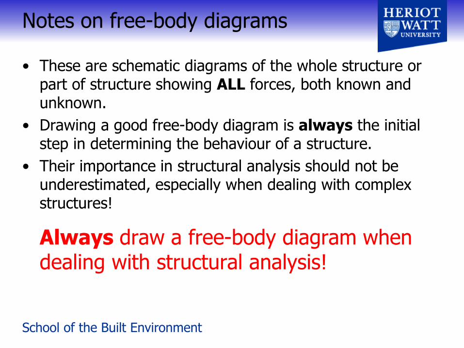
Notes on free-body diagrams
• These are schematic diagrams of the whole structure or part of structure showing ALL forces, both known and unknown.
• Drawing a good free-body diagram is always the initial step in determining the behaviour of a structure.
• Their importance in structural analysis should not be underestimated, especially when dealing with complex structures!
Always draw a free-body diagram when dealing with structural analysis!

School of the Built Environment
Short break....
(Be back in 10 minutes)

School of the Built Environment
Determinacy of a structure
• When all forces in a structure can be determined strictly from equilibrium equations:
structure said to be statically determinate
• For structures having more unknown forces than available equilibrium equations:
referred to as statically indeterminate
• Determinacy of a structure therefore found from comparing number of unknown forces / moments with total number of equilibrium equations:
– generally found from drawing free-body diagram of whole, or selective parts, of structure.

School of the Built Environment
Determinacy of a structure
• Example: consider a beam supported by two tension cables, as shown:
• From equilibrium equations:
H = 0: No horizontal forces in system
V = 0: VA + VB – W = 0 VA = W – VB
M@A = 0: VB L – W L/2 = 0 VB = WL/2L = W/2
VA = W/2
statically determinate
W
A B
W
VA VB
Free-body diagram
L

School of the Built Environment
Determinacy of a structure
• Example: what happens when we introduce a third support cable:
• Again, from equilibrium equations:
H = 0: Still no horizontal forces in system
V = 0: VA + VB + VC – W = 0 VA = W – VB – VC
M@A = 0: VB L + VC L1 – W L/2 = 0
• Only 2 useful equations and 3 unknowns
statically indeterminate
W
A B
L1
C
L2
W
VA VB
Free-body diagram
VC

School of the Built Environment
• For coplanar (2D) structures, only three independent equilibrium equations exist (e.g. H = 0; V = 0; M = 0):
• For a total of n parts of the structure and r unknown reactive force or moment components, we have:
r = 3n, statically determinate
r > 3n, statically indeterminate
• If a structure is statically indeterminate, additional equations are required to solve for all unknown forces:
– Compatibility equations (beyond the scope of this course).
– No. required = no. of unknowns = degree of indeterminacy
Determinacy of a structure (2)

School of the Built Environment
Determinacy of a structure (3)
• Examples: (a) beams Free-body diagrams
r = 3, n = 1 3 = 3(1) Statically determinate
r = 5, n = 1 5 > 3(1) Statically indeterminate (to second degree)
r = 6, n = 2 6 = 3(2) Statically determinate
r = 10, n = 3 10 > 3(3) Statically indeterminate (to first degree)
School of the Built Environment
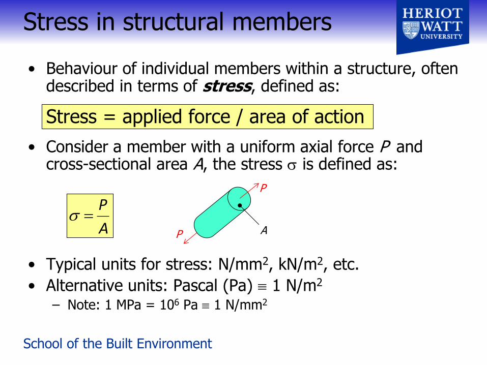
• Behaviour of individual members within a structure, often described in terms of stress, defined as:
Stress = applied force / area of action
• Consider a member with a uniform axial force P and cross-sectional area A, the stress is defined as:
• Typical units for stress: N/mm2, kN/m2, etc.
• Alternative units: Pascal (Pa) 1 N/m2
– Note: 1 MPa = 106 Pa 1 N/mm2
Stress in structural members
A
P
P
P A

School of the Built Environment
1. Compression
2. Tension
3. Shear
• Most loads can be analysed in terms of these three stresses:
– Example: bending of a beam involves compression, tension and shear at different places in the beam (as will be shown later in course)
Types of stress (and force)

School of the Built Environment
In-lecture question
• A steel reinforcement bar of diameter (D) 15 mm has an axial tensile force P of 15 kN applied to it.
What is the tensile stress within the bar?
Answer:
Cross-sectional area of steel A = .d2/4 = 176.7 mm2
Tensile stress = P/A = 15,000/176.7 = 84.9 N/mm2
P =15 kN
A = 3.14 x 𝐷2
4 = 3.14 x
152
4 mm2 Cross-sectional area :
Tensile stress: σ = F
𝐴 =
15 (kN)
3.14 x 1524 (mm2)
= 1 (kN)
3.14 x 154 (mm2)
σ = 0.85 ( kN mm2 ) = 0.85 ( 1000 N
mm2 ) = 850 ( N mm2 ) => σ = 850 MPa
Bar cross-section :

School of the Built Environment
• In response to an applied stress, a member can change shape i.e. ‘deform’.
• Resulting deformation is called strain, defined as follows:
Strain = change in length / original length
• Strain is dimensionless (length/length), but may be expressed as a fraction or a percentage, i.e.
– mm/mm or mm/mm 100 %
• However, because strains are also normally very small number, they are often expressed as micro strain :
– 1 (1 micro-strain) 1 10-6
Structural response to stress

School of the Built Environment
Types of strain
1. Tension
Original length
Length after extension
Extension =
Strain = / L or / L 100%
• Note: magnitude of strain is independent of member length:
– A strain of 1 x 10⁻³ (0.1%) is equivalent to an extension of 1 mm in 1 m or 100 mm in 100 m.
L
L +

School of the Built Environment
Types of strain
2. Compression
3. Shear
• In both cases = /L, as before
L
L

School of the Built Environment
In-lecture question (5)
• A 20 metre long wire supporting an axial tensile load stretches by 5 mm.
What is the strain in the wire? Express as percentage and as a micro-strain.
Answer:
/L = 5 / 20,000 = 0.00025 = 0.025 % = 250
= / L = 5mm / 20m =
= 5mm / 20000mm =
= 0.00025 mm/mm or 0.025%
L = 20 m 5 mm

School of the Built Environment
Linear-elastic behaviour
• Many materials behave in a linear-elastic manner at working loads within structures:
– Strain in a member increases linearly with applied stress
– Much of structural analysis based on linear-elastic behaviour
• Note: linear elastic behaviour is reversible:
– but only if material yield point or elastic limit has not been exceeded.
Str
ess
Strain
Relationship between stress and strain:
where E is known as the ‘modulus of elasticity’ or Young’s modulus (units same as stress, but often expressed in kN/mm2)
E

School of the Built Environment
Elastic behaviour: material stiffness
• Material stiffness defined by the amount of strain experienced by material for a given applied stress :
– A stiff material has a high / ratio (i.e. high Young’s modulus)
– e.g. steel E = 200 kN/mm2 (GPa)
– A flexible material has a low / ratio (i.e. low Young’s modulus)
– e.g. rubber E = 1 x 10⁻³ kN/mm2 (GPa) Str
ess
Strain
stiff
flexible

School of the Built Environment
Beyond the Elastic limit
• Yield point = the stress level at which the material yields and starts to deform irreversibly.
• Above the yield point the material flows continuously under the applied stress – Plastic behaviour
stress
strain
Plastic region
Elastic region
Yield point stress
Elastic limit
School of the Built Environment
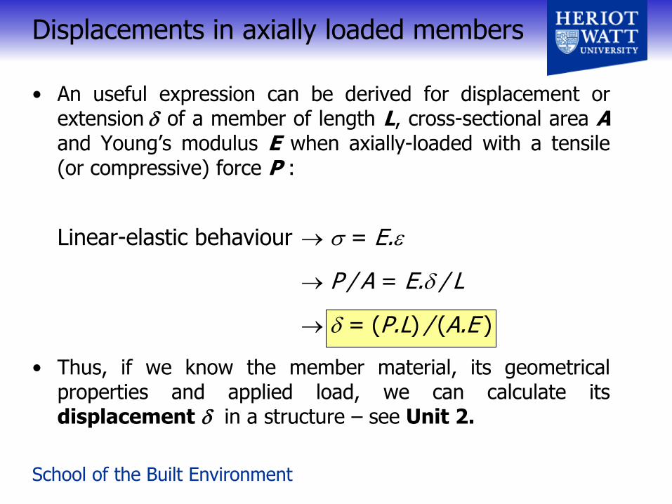
• An useful expression can be derived for displacement or extension of a member of length L, cross-sectional area A and Young’s modulus E when axially-loaded with a tensile (or compressive) force P :
Linear-elastic behaviour = E.
P / A = E. / L
= (P.L) / (A.E )
• Thus, if we know the member material, its geometrical properties and applied load, we can calculate its displacement in a structure – see Unit 2.
Displacements in axially loaded members

School of the Built Environment
In lecture question
• A 20 mm diameter steel bar is subjected to a axial tensile force of F=35 kN, calculate the tensile stress and strain assuming Young’s modulus for steel Es =200 kN/mm2.
• If the bar is 5 m long, what is the overall displacement for an increased load of 45 kN?
Answer: Bar area A = D2/4 = 314.16 mm2
Stress = F/A = 35000/314.16 = 111.4 N/mm2
Strain = /E = 111.4/200103 = 5.5710-4
Displacement = FL/AE = 455000/(314.16200) = 3.58 mm
School of the Built Environment
Upcoming Sessions
• Thursday 19th September (09:15 – 11:15)
– UNIT 1: Forces in pin-jointed frames