d2 turbo and d2 turbo low-voltage installation manual d2... · the d2 turbo low-voltageis a...
TRANSCRIPT

D2 Turbo and D2 Turbo Low-Voltage Installation Manual
Centurion Systems (Pty) Ltd www.CentSys.com
After-sales
multi-languageTechnical Support
from 07h00 to 18h00 UTC+2
Monday to Friday
Manufacture tointernational
quality standardISO 9001:2008
100% testing of products
In-houseR&Ddevelopmentteam
Centurion Systems (Pty) Ltd reserves the right to make changes to the products described in this manual without notice and without obligation to notify any persons of any such revisions or changes. Additionally, Centurion Systems (Pty) Ltd makes no representations or warranties with respect to this manual. No part of this document may be copied, stored in a retrieval system or transmitted in any form or by any means electronic, mechanical, optical or photographic, without the express prior written consent of Centurion Systems (Pty) Ltd.
1986 1990 1995 1999 Today
CO
MP
AN
Y P
RO
FILE
Company Profile
Sales and technical support to Africa, Europe, Asia, the Americas, Australia
and the Pacific
page 3www.CentSys.com
FAST TRACK
Mechanical SetupElectrical SetupCommissioning and Handover
page 5page 6page 6
SAFETYFIRST IMPORTANT SAFETY INSTRUCTIONS
Glossary of Terms
1. General Description
2. Icons Used in this Manual
3. Specifications
3.1. Physical Dimensions
3.2. TechnicalSpecifications
4. Product Identification
5. Required Tools and Equipment
6. D2 Turbo Low-voltage Site Considerations
7. Preparation of Site
8. Cabling Requirements
9. Lubrication
10. Operator Installation
10.1. Foundation plate installation
10.2. Route Cables and Secure Foundation Plate
10.3. Mount the gearbox
10.4. Mount the rack
10.5. Mount the origin marker
10.6. Apply warning decal
11. Electrical Setup
11.1. Connect all Wiring
11.2. Wiring Diagram for Closing Safety Beams/ Photocells
11.3. Wiring Diagram for Opening Safety Beams/ Photocells
11.4. Wiring Diagram for External Radio Receiver
page 7
page 9
page 11
page 12
page 13
page 13
page 13
page 15
page 16
page 17
page 18
page 21
page 22
page 23
page 25
page 31
page 31
page 34
page 38
page 41
page 42
page 42
page 43
page 44
page 45
Contents
CO
NT
EN
TS

page 4 www.CentSys.com
page 46
page 47
page 48
page 49
page 50
page 51
page 52
page 53
page 55
page 67
page 86
page 88
page 89
page 93
page 94
page 95
page 96
page 97
page 99
11.5. Wiring Diagram for Other Inputs
11.6. Wiring Diagram for Pillar Light to D2 Turbo
11.7. Wiring Diagram for Pillar Light to D2 Turbo Low-Voltage
11.8. Wiring Diagram for Solar Panel to D2 Turbo
11.9. Wiring Diagram for Solar Panel to D2 Turbo Low-Voltage
11.10. Mains Supply and Battery Connections
11.11.EarthingforEffectiveLightningProtection
12. Commissioning the System
13. Features and Functions
14. Customising the Features and Functions
15. Description of Terminal Functions
16. Diagnostics
17. Troubleshooting
18. Manual Operation
19. Additional Features
20. Basic Maintenance
21. Servicing the Operator
22. 24 Month Carry-in Product Warranty
23. Installation Handover
CO
NT
EN
TS

page 5www.CentSys.com
ME
CH
AN
ICA
L SE
TU
P
STEP1
These abbreviated instructions are for the experienced installer who needs a checklist to get a standard installation up and running in the minimum of time.
Detailed installation features and functions are referred to later in this manual.
Gather Required Tools and Equipment
STEP2
STEP3
Heed Necessary Site Considerations
Cabling requirements
STEP4
Lubrication
STEP5
STEP6
STEP7
STEP8
STEP9
Foundation plate installation
Cabling and Wiring
Mount Gearbox
Mount the Rack
Operator installation
FAST TRACK Mechanical Setup
FAS
T T
RA
CK
page 16
page 17
page 21
page 22
page 23
page 25
page 31
page 31
page 34

page 6 www.CentSys.com
ME
CH
AN
ICA
L S
ET
UP
Connect all wiring
Set the gate limits
Set additional features
Carry out a Professional Handover to Client
STEP10
STEP11
STEP12
STEP13
Electrical Setup
Commissioning & Handover
FAS
T T
RA
CK
page 42
page 53
page 67
page 99
page 7www.CentSys.com
SA
FET
Y FIR
ST
IMP
OR
TA
NT
SA
FET
Y IN
ST
RU
CT
ION
S
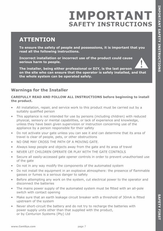
ATTENTIONTo ensure the safety of people and possessions, it is important that you read all the following instructions.
Incorrect installation or incorrect use of the product could cause serious harm to people.
The installer, being either professional or DIY, is the last person on the site who can ensure that the operator is safely installed, and that the whole system can be operated safely.
IMPORTANT SAFETY INSTRUCTIONS
Warnings for the Installer CAREFULLY READ AND FOLLOW ALL INSTRUCTIONS before beginning to install the product.
• All installation, repair, and service work to this product must be carried out by a suitablyqualifiedperson
• This appliance is not intended for use by persons (including children) with reduced physical, sensory or mental capabilities, or lack of experience and knowledge, unless they have been given supervision or instruction concerning use of the appliance by a person responsible for their safety
• Do not activate your gate unless you can see it and can determine that its area of travel is clear of people, pets, or other obstructions
• NO ONE MAY CROSS THE PATH OF A MOVING GATE. • Always keep people and objects away from the gate and its area of travel• NEVER LET CHILDREN OPERATE OR PLAY WITH THE GATE CONTROLS• Secure all easily-accessed gate opener controls in order to prevent unauthorised use
of the gate• Do not in any way modify the components of the automated system• Donotinstalltheequipmentinanexplosiveatmosphere:thepresenceofflammable
gasses or fumes is a serious danger to safety• Before attempting any work on the system, cut electrical power to the operator and
disconnect the batteries• Themainspowersupplyoftheautomatedsystemmustbefittedwithanall-pole
switch with contact opening• Makesurethatanearthleakagecircuitbreakerwithathresholdof30mAisfitted
upstream of the system• Never short-circuit the battery and do not try to recharge the batteries with
power supply units other than that supplied with the product, or by Centurion Systems (Pty) Ltd

page 8 www.CentSys.com
IMP
OR
TA
NT
SA
FET
Y I
NS
TR
UC
TIO
NS
SA
FET
Y F
IRS
T
• Make sure that the earthing system is correctly constructed, and that all metal parts of the system are suitably earthed
• Safetydevicesmustbefittedtotheinstallationtoguardagainstmechanicalmovement risks such as crushing, dragging and shearing
• Itisrecommendedthatatleastonewarningindicatorlightbefittedtoeverysystem• Alwaysfitthewarningsignsvisiblytotheinsideandoutsideofthegate• The installer must explain and demonstrate the manual operation of the gate in case
of an emergency, and must hand the User Guide/Warnings over to the user• Explain these safety instructions to all persons authorised to use this gate, and be
sure that they understand the hazards associated with automated gates• Do not leave packing materials (plastic, polystyrene, etc.) within reach of children as
such materials are potential sources of danger• Dispose of all waste products like packing materials, worn- out batteries, etc.,
according to local regulations• Always check the obstruction detection system, and safety devices for correct
operation• Neither Centurion Systems (Pty) Ltd, nor any of its subsidiaries, accepts any liability
caused by improper use of the product, or for use other than that for which the automated system was intended
• This product was designed and built strictly for the use indicated in this documentation. Any other use, not expressly indicated here, could compromise the service life/operation of the product and/or be a source of danger

page 9www.CentSys.com
GLO
SS
AR
Y O
F TE
RM
S
• DOSS: Digital Origin Seeking System. An opto-electronic system that counts pulses in order to determine the position of the gate and the distance that it needs to travel to its respective endstops
• IRBO: Opening infrared Safety Beams. If the opening beams are interrupted while the gate is in the closed position, it will prevent the gate from opening. If they are interrupted while the gate is travelling in the open direction, it will stop and close the gate.Itwillhavenoeffectuponaclosinggate
• IRBC: Closing infrared Safety Beams. If the closing beams are interrupted while the gate is in the open position, it will prevent the gate from closing. If they are interrupted while the gate is closing, it will stop and open the gate. Itwillhavenoeffectuponanopeninggate
• PIRAC Mode: Passive infrared Autoclose Mode. This feature allows the gate to close automatically as soon as a vehicle or pedestrian has passed through the closing beam. This security feature ensures that the gate stays open for the minimum amount of time possible, thus maximising security at the entrance
Glossary of Terms

page 10 www.CentSys.com
DE
CLA
RA
TIO
N O
F C
ON
FOR
MIT
Y
Declaration of Conformity
Manufacturer Centurion Systems (Pty) Ltd Unit 13 Production Park Intersection of Newmarket Road and Epsom Avenue North Riding Gauteng South Africa
Declares that the productProduct name: D2 Turbo/D2 Turbo Low-Voltage Sliding gate operator.
Conforms with the following specificationsEmissions: CISPR11CLASSA-RadiatedandconductedInterferencefield strength (emission tests) – 150KHz TO 6GHz
Immunity: IEC 61000-4-2 – Electrostatic discharge IEC 61000-4-3 – Radiated immunity – 80MHz TO 1000MHz IEC 61000-4-4 – Electrical fast transients/burst IEC 61000-4-5 – Surges IEC 61000-4-6 – Conducted immunity – 150KHz TO 80MHz IEC 61000-4-11– Voltage dips and interruption
Standard to which conformity is declared IEC 60335-1:2006 Safety IEC 61000-6-4:2006 Emissions IEC 61000-6-2:2005 Immunity
Signed at North Riding, South Africa on April 14, 2010
Ian RozowskyResearch & Development Director

page 11www.CentSys.com
The D2 Turbo is designed to open and close domestic sliding gates weighing up to 250kg. The gearbox, moulded from a high-tech engineering polymer not only looks good, but is corrosion-free and guarantees that even if you live on the coast, your D2 Turbo will just keep ongoing.ArobuststeelpinionensuresthatyourD2Turbocaneasilyberetrofittedonsites with existing steel rack and will deliver years of reliable service.
TheD2TurboLow-Voltageisacost-effectivedomesticslidinggatemotorforgatesweighing up to 250kg. Its logic controller and onboard charger require only a low-voltage AC or DC input, which means there is no need for costly high-voltage cable runs or expensive isolators.
The integral 12V 5Ah battery (charged by an internal charger) comes with full battery backup and advanced lightning protection so you can always get in – even when the power is out. For increased power capacity you can install a larger, 7Ah battery (your D2 Turbo was designed to cater for this), or you can even use a solar panel to power it (See the section on Solar Panels, for more details about solar charging).
Advanced features of the D2 Turbo logic controller:The D2 Turbo has various useful features and functions, all easily-accessible from a user-friendly dial-based setup system:• Opening and closing safety beam inputs with beam circuit functional test1
• High-security cleared-beam Autoclose in conjunction with safety beams (PIRAC)1
• Multiple Modes of Operation: Standard Mode, Open only Mode (multi-user), ReversingMode,andtwoPre-flashingModes
• Automatic closing with adjustable time delay, and pushbutton override• Remote gate-status indicator (gate position, power failure, low battery,
multiple collision detection and Pillar Light status indication)2
• Pedestrian Opening3 (with adjustable Autoclose time)• Holiday Lockout3
• Courtesy/Pillar-Lighttimer(fixedduration),withpre-delaysandtwoPre-flashingModes4
• Selectable gate speed modes - Low Speed/High Speed (High Speed is the default)• Positive Close Mode (e.g. ensure activation of electric fence contact switch)• Onboard multichannel code-hopping receiver with the ability to learn transmitter buttons
tospecificfunctions(e.g.Gatetrigger,PedestrianOpening,HolidayLockout)1.InfraredSafetyBeamsorequivalentdetectiondevicemustbefitted2.RemoteLEDmustbefitted3.Onboardreceivermustbeusedorexternalaccesscontroldevicesuchasakeypadorkeyswitchthatmustbefitted4.PillarLights/Pre-flashwarninglightmustbefitted
GE
NE
RA
L DE
SC
RIP
TIO
N
1. General Description
SE
CT
ION
1

page 12 www.CentSys.com
2. Icons Used in this Manual
This icon indicates tips and other information that could be useful during the installation.
This icon denotes variations and other aspects that should be considered during installation.
This icon indicates warning, caution or attention! Please take special note of critical aspects that MUST be adhered to in order to prevent injury.
ICO
NS
US
ED
IN
TH
IS M
AN
UA
LS
EC
TIO
N 2

page 13www.CentSys.com
SP
EC
IFICA
TIO
NS
SE
CT
ION
3
3.1. Physical Dimensions
3.1. Technical specifications
3. Specifications
FIGURE 1. OVERALL DIMENSIONS
31
0m
m
244mm 170mm
60
mm
D2 Turbo D2 Turbo Low-Voltage
Supply Voltage 90V - 240V AC ± 10%, 50Hz1
10V - 20V AC1 10V - 28V DC1
Battery Charger Amperage Output (dependant on PSU input voltage)
Voltage output: 13.76V DC
90V AC Input
1A Output
10V AC Input
400mA Output
20V AC Input
1A Output
240V AC Onput
1.2A Output
10V DC Input
200mA Output
20V DC Input
1A Outpu
Motor voltage 12V DCMotor Power Supply Battery-driven (Standard Capacity - 12V 5Ah)2
Current Consumption (mains) 70mA NA

page 14 www.CentSys.com
SE
CT
ION
3S
PE
CIF
ICA
TIO
NS
D2 Turbo D2 Turbo Low-VoltageCurrent Consumption (motor at rated load) 8A
Operator Push Force - Starting 18kgf
Operator Push Force - Rated 9kgfGate Mass - Maximum 250kgGate Length - Maximum 20mGate Speed (Varies with Load)3 24m/min
Manual Override Lockable with Key ReleaseLife Expectancy of Electric Motor Ten Years (based on ten operations per day)
Duty Cycle - Mains Present4,5 50%Operations in Standby with 5Ah Battery
Half Day6
Full Day63015
Collision Sensing ElectronicOperating Temperature Range -15°C to +50°C
Onboard Receiver Type Code-hopping Multichannel Receiver with Selective add and Delete
Receiver Code Storage Capacity 32 Transmitter Buttons
Receiver Frequency 433.92MHzDegree of Protection IP44Mass of Unit Packed (with standard kit, but excl. rack and battery)
4.83kg
Packaging Dimensions (with standard kit, but excl. rack and battery)
255mm wide x 188mm deep x 333mm high
TABLE 11.Canoperateoffasolarsupply,consultyourlocaldealerforassistance
2. Can increase battery capacity to 7Ah for longer standby times
3.Gateoperatingspeedcanbeconfiguredtorunslowerdependingontherequirementsofindividualinstallations
4. Based on 25°C ambient temperature and unit not in direct sunlight
5. Based on an operator push force of less than 50% of rated
6. Based on four metre gate, excluding infrared Safety Beams

page 15www.CentSys.com
SE
CT
ION
4P
RO
DU
CT
IDE
NT
IFICA
TIO
N
1. Motor fuse2. D2 Turbo 220V orange controller and
D2 Turbo Low-Voltage dark-green controller
3. 12V 7.2Ah or 5Ah battery4. Motor enclosure unit5. Camlock cover6. Manual Release thumbwheel7. Foundation plate8. Gate-mounted origin marker9. Origin marker bracket 10. Selection knob
11. Status LED12. Function Dial13. Selection knob14. Battery strap15. Spare fuse16. Pulley guard17. Pinion18. Pinion guard 19. Motor housing
4. Product Identification
FIGURE 2. PRODUCT IDENTIFICATION
1
2
3
10
11
12
13
14
15
16
19
17
18
4
5
6
7
8
9
Refer to the drawings below, for how to identify your D2 Turbo/D2 Turbo Low-Voltage motor and its parts.

page 16 www.CentSys.com
RE
qU
IRE
D T
OO
LS &
Eq
UIP
ME
NT
5. Required Tools & Equipment
SE
CT
ION
4
Spanners17mm/15mm
preferably socket set
Crimping tooland Pin lugs
Ø12mm masonry drill bit for wall mount bracket
Ø6.5mm steel drill bit for gate bracket
Connectorblock
Hole saw20mm
Angle grinder
Pin punch6mm
Hacksaw
Spirit level
Markingpen/chalk
Extension cord
Soldering iron
Safety equipment (goggles, gloves etc.)
Welding machine(including consumables)
and safety equipment
Measuringtape
G-clamps x2
Allen key5mm
Electric drillingmachine
Screwdrivers6mm Phillips3.5mm Flat
Hammer
Pliers
FIGURE 3. REqUIRED TOOLS & EqUIPMENT

page 17www.CentSys.com
D2
TU
RB
O LO
W-V
OLT
AG
E S
ITE
CO
NS
IDE
RA
TIO
NS
6. D2 Turbo Low-voltage Site Considerations
SE
CT
ION
6
IMPORTANT Site Considerations for the D2 Turbo Low-VoltageBefore you attempt to use your new gate motor for the first time, you should know::• At no point must 220V be supplied to the system! This is a low-voltage
model and connecting a mains voltage supply that exceeds its maximum specifications will irreparably damage the electronics
• No earth terminal is provided for the incoming power, and is not necessary, but the earthing lead must still be grounded to the motor base plate as this serves as lightning protection
• The thickness of the cable needed to supply power to the system will depend on the distance between the transformer and the motor, as well as on the output voltage of the transformer used. The table below shows the typical cable thicknesses for corresponding distance and assumes a 16V AC transformer output
Distance from transformer to operator Minimum cable thickness requiredUp to 20m 1mm2
20m - 40m 1.5mm2
40m - 60m 2.5mm2

page 18 www.CentSys.com
7.1. EndstopsFitendstopscapableofstoppingthegateatratedspeed.Refertospecificationsatthebeginning of this manual for the operating speed
Make H>h to ensure gate will not jump over endstop
7. Preparation of Site
FIGURE 4. FITTING ENDSTOPS
PR
EP
AR
AT
ION
OF
SIT
ES
EC
TIO
N 7
WARNING!Endstops are mandatory and must be fitted to prevent deathor accidental injury should the gate overrun its limit. They are also required to complete the setup procedure.
Endstop
EndstopØ16mmH
h
7.2. General Considerations for the InstallationAlwaysrecommendthefitmentofadditionalsafetyequipmentsuchasSafetyEdgesand Safety Beams/Photocells, for additional protection against entrapment or other mechanical risks.
Check that no pipes or electrical cables are in the way of the intended installation
Check that enough space is available for the gate operator with the gate in the required open position.
Check for loose, sandy soil if installing foundations, as the soil condition may require a larger foundation.
Neverfittheoperatorontheoutsideofthegate,wherethepublichasaccesstoit.
7.3. Install the gate operator only if:It will not pose a hazard to the public.
Thereissufficientclearancetoaroadwayand/orpublicthoroughfares
page 19www.CentSys.com
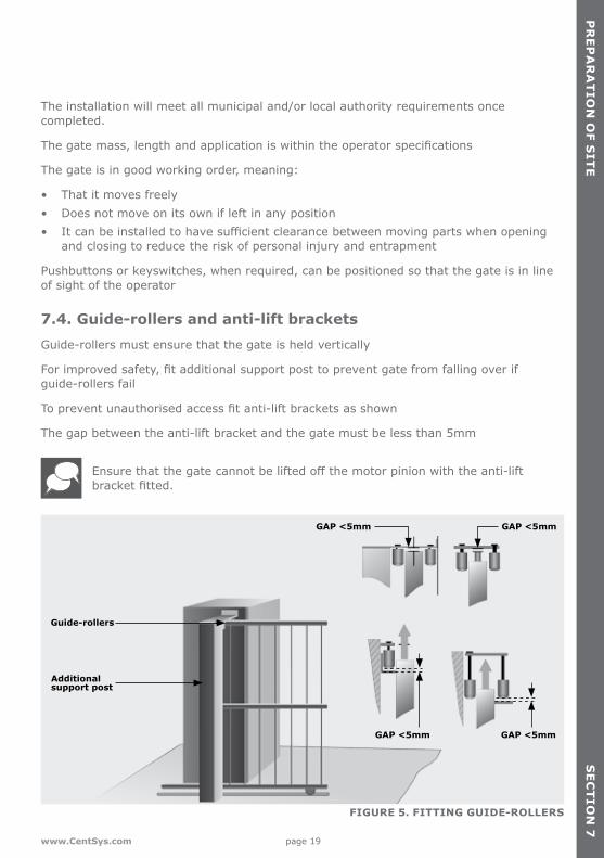
FIGURE 5. FITTING GUIDE-ROLLERS
PR
EP
AR
AT
ION
OF S
ITE
SE
CT
ION
7
Guide-rollers
Additional support post
The installation will meet all municipal and/or local authority requirements once completed.
Thegatemass,lengthandapplicationiswithintheoperatorspecifications
The gate is in good working order, meaning:
• That it moves freely• Does not move on its own if left in any position• Itcanbeinstalledtohavesufficientclearancebetweenmovingpartswhenopening
and closing to reduce the risk of personal injury and entrapment
Pushbuttons or keyswitches, when required, can be positioned so that the gate is in line of sight of the operator
7.4. Guide-rollers and anti-lift bracketsGuide-rollers must ensure that the gate is held vertically
Forimprovedsafety,fitadditionalsupportposttopreventgatefromfallingoverif guide-rollers fail
Topreventunauthorisedaccessfitanti-liftbracketsasshown
The gap between the anti-lift bracket and the gate must be less than 5mm
Ensurethatthegatecannotbeliftedoffthemotorpinionwiththeanti-liftbracketfitted.
GAP <5mm
GAP <5mm GAP <5mm
GAP <5mm
page 20 www.CentSys.com
PR
EP
AR
AT
ION
OF
SIT
ES
EC
TIO
N 7
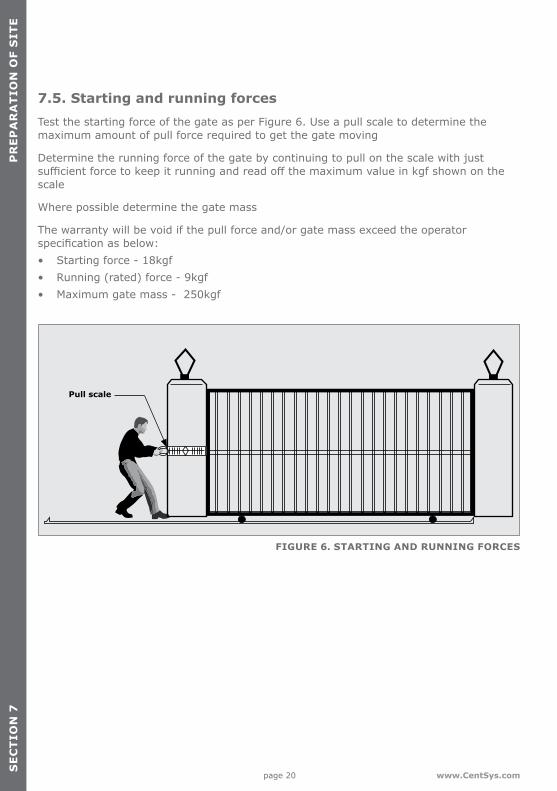
7.5. Starting and running forces Test the starting force of the gate as per Figure 6. Use a pull scale to determine the maximum amount of pull force required to get the gate moving
Determine the running force of the gate by continuing to pull on the scale with just sufficientforcetokeepitrunningandreadoffthemaximumvalueinkgfshownonthescale
Where possible determine the gate mass
The warranty will be void if the pull force and/or gate mass exceed the operator specificationasbelow:• Starting force - 18kgf• Running (rated) force - 9kgf• Maximum gate mass - 250kgf
FIGURE 6. STARTING AND RUNNING FORCES
Pull scale

page 21www.CentSys.com
CA
BLIN
G R
Eq
UIR
EM
EN
TS
SE
CT
ION
8
Legend 1. D2 Turbo: 220V - 240V AC mains cable via double mains isolator switch
(3 core LNE 1.5mm2 SWA) D2 Turbo Low-Voltage: 10V - 20V AC or 10-28V DC cable via transformer in dwelling1
Optional Wiring (all cable is multi-stranded):2. Intercom, cable from control box to dwelling (n1 6 + 6 core 2 0.5mm² multi-
stranded) or cable from control box to entry panel (n2 6 0.5mm² multi-stranded)3. Infrared Safety Beams (3 core 0.5mm² multi-stranded)4. Access control device (3 core 0.5mm² multi-stranded4)5. Pedestrian keyswitch (2 core 0.5mm² multi-stranded) or6. Keypad (3 core 0.5mm² multi-stranded)7. External radio receiver (3 core 0.5mm² multi-stranded5)8. Pillar Lights (3 core LNE SWA2, size according to power requirements)9. Inductive loop detector for free-exit
(1 core 0.5mm² multi-stranded - silicone-coated6)1. Possibly increase cable thickness if Pillar Lights are to be installed
2. SWA - steel wire armoured. Type of cable must adhere to municipal bylaws and preferably be screened. Screening provides better protection against lightning - earth one end of the screening
3. Allows for all features such as Pedestrian Opening, Status LED, etc. to be operated from the intercom handset inside the dwelling
4. Number of cores and type of cable could vary depending on the brand of access control system being used
5. For optimum range an external radio receiver can be mounted on the wall
6. Number of cores required by the intercom
FIGURE 7. CABLING REqUIREMENTS
8. Cabling Requirements
Mains isolator switch
5
6
9
1
1
2
2
3
3
8
84

page 22 www.CentSys.com
ThegearboxoftheD2Turboisfilledwithgreaseduringtheassemblyprocess,andthegearset does not have to be lubricated ex-factory.
LUB
RIC
AT
ION
SE
CT
ION
9
9. Lubrication
page 23www.CentSys.com
FIGURE 8B. BELOW PINION - RAZ RACKFIGURE 8A. ABOVE PINION - RAZ RACK
OP
ER
AT
OR
INS
TA
LLAT
ION
SE
CT
ION
10
10. Operator Installation
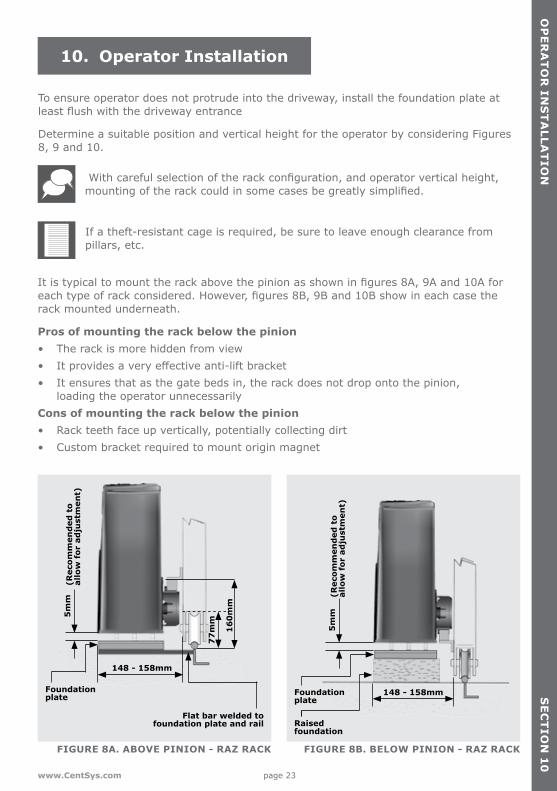
To ensure operator does not protrude into the driveway, install the foundation plate at leastflushwiththedrivewayentrance
Determine a suitable position and vertical height for the operator by considering Figures 8, 9 and 10.
Withcarefulselectionoftherackconfiguration,andoperatorverticalheight,mountingoftherackcouldinsomecasesbegreatlysimplified.
If a theft-resistant cage is required, be sure to leave enough clearance from pillars, etc.
Itistypicaltomounttherackabovethepinionasshowninfigures8A,9Aand10Aforeachtypeofrackconsidered.However,figures8B,9Band10Bshowineachcasetherack mounted underneath.
Pros of mounting the rack below the pinion• The rack is more hidden from view• Itprovidesaveryeffectiveanti-liftbracket• It ensures that as the gate beds in, the rack does not drop onto the pinion,
loading the operator unnecessarilyCons of mounting the rack below the pinion• Rack teeth face up vertically, potentially collecting dirt• Custom bracket required to mount origin magnet
(Rec
omm
end
ed t
o al
low
for
ad
just
men
t)
(Rec
omm
end
ed t
o al
low
for
ad
just
men
t)
Flat bar welded tofoundation plate and rail
Foundationplate
Raised foundation
Foundationplate
5m
m
5m
m
148 - 158mm
148 - 158mm
16
0m
m
77
mm

page 24 www.CentSys.com
OP
ER
AT
OR
IN
ST
ALL
AT
ION
SE
CT
ION
10
FIGURE 9B. ABOVE PINION - NYLON ANGLE RACK
FIGURE 10B. ABOVE PINION - STEEL RACK
FIGURE 9A. ABOVE PINION - NYLON ANGLE RACK
FIGURE 10A. ABOVE PINION - STEEL RACK
* Includes 3mm clearance required between rack and pinion
13
0m
m*
17
4m
m*
77
mm
74
mm
(Rec
omm
end
ed t
o al
low
for
ad
just
men
t)
Flat bar welded tofoundation plate and rail
Foundationplate
5m
m
148 - 158mm
(Rec
omm
end
ed t
o al
low
for
ad
just
men
t)Raised foundation
Foundationplate
5m
m
148 - 158mm
* Includes 3mm clearance required between rack and pinion
(Rec
omm
end
ed t
o al
low
for
ad
just
men
t)
Flat bar welded tofoundation plate and rail
Foundationplate
5m
m
146mm
(Rec
omm
end
ed t
o al
low
for
ad
just
men
t)
Raised foundation
Foundationplate
5m
m
146mm

page 25www.CentSys.com
OP
ER
AT
OR
INS
TA
LLAT
ION
SE
CT
ION
10
FIGURE 11
FIGURE 12
FIGURE 13
Foundationplate
Gate rail
Flat bar welded to foundation plate and rail
10.1. Foundation plate installation
When using a concrete foundation it is recommended that the foundation plate is welded to the rail/track of the gate using short length offlatbar,asinFigure11. This makes it possible to complete the whole mechanical and electrical installation, without having to wait for the concrete to set. After completing the installation the concrete can be poured and the operator left in the Manual Mode until the concrete has set.
The foundation plate can either be set into a concrete foundation, as in Figures 12 to 18, or bolted down onto an existing concrete plinth as shown in Figure 19 and 20. If the D2 Turbo is being used to replace a D3 gate operator, refer to Figures 22 to 27.
Option 1: Cast foundation plate into concrete
Bend the anchor brackets outwards as shown in Figure 13.

page 26 www.CentSys.com
OP
ER
AT
OR
IN
ST
ALL
AT
ION
FIGURE 16
SE
CT
ION
10
FIGURE 14
FIGURE 15
Using a pair of long-nosed pliers, bend the ends of the anchor brackets at a 90° angle.
Fit the mounting bolts to the foundation plate and secure in place with nuts and washer.
Long-nosed pliers
M10 washer
M10 gearboxmounting bolts
Anchorbrackets
M10 nut
page 27www.CentSys.com
FIGURE 19
OP
ER
AT
OR
INS
TA
LLAT
ION
SE
CT
ION
10
FIGURE 17
FIGURE 18
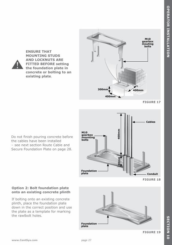
Donotfinishpouringconcretebeforethe cables have been installed – see next section Route Cable and Secure Foundation Plate on page 28.
Conduit
Cables
M10 gearbox mounting bolts 4
00
mm
40
mm
ENSURE THAT MOUNTING STUDS AND LOCKNUTS ARE FITTED BEFORE setting the foundation plate in concrete or bolting to an existing plate.
Option 2: Bolt foundation plate onto an existing concrete plinth
If bolting onto an existing concrete plinth, place the foundation plate down in the correct position and use the plate as a template for marking the rawlbolt holes.
300mm
400mm
400mm
M10gearboxmouting
bolts
Foundationplate
Foundationplate

page 28 www.CentSys.com
OP
ER
AT
OR
IN
ST
ALL
AT
ION
SE
CT
ION
10
FIGURE 20
FIGURE 21
Conduit
Cables
M10 gearbox mounting bolts 4
00
mm
40
mm
Route Cables and Secure Foundation Plate
Route cables as determined in Section 7, Cabling Requirements.
Make sure that all cables and conduits protrude at least 400mm above the foundation plate once installed.
Securely concrete or bolt the foundation plate in position.
Do not bend out the anchor brackets.
Fit the mounting studs to the foundation plate and secure in place with the stud locknuts.
M10 nut
Anchor brackets
M10 washer
M10 gearbox mounting bolts
Use two M12 plated nuts as spacers
M10 x 95expansion stud
Foundationplate

page 29www.CentSys.com
OP
ER
AT
OR
INS
TA
LLAT
ION
SE
CT
ION
10
FIGURE 22
FIGURE 23
FIGURE 24
Option 3: Retrofitting D2 Turbo to an existing D3 foundation plate.
Grindofftheexistingmountingstuds from the D3 foundation plate as shown in Figure 22.
Fit the three mounting studs to the D2 Turbo foundation plate and secure in place using the stud locknuts supplied with this kit. The half-height nuts should be used on the underside of the plate as shown in Figure 23, as these will later be used for height adjustment. However, if space allows –i.e.therewillbesufficientclearance between the rack and the pinion once the operator has been mounted – the orange height-adjustment nuts may be used
Do not attempt to mount the gearbox without using either the half-height nuts or the orange jacking nuts as doing so will result in the gearbox being damaged when the hold-down nuts are tightened.
Mounting studs
D3 foundation plate
Grinder
Stud locknut(M10 half-height nut)
Stud locknut(M10 half-height nut)
Mounting stud
Orange height-adjustment nuts
Washer

page 30 www.CentSys.com
OP
ER
AT
OR
IN
ST
ALL
AT
ION
SE
CT
ION
10
FIGURE 27
FIGURE 25
FIGURE 26
Use the supplied full-height hold-down nuts to temporarily secure the plate in place from above as shown in Figure 24.
Place the D2 Turbo foundation plate onto the existing D3 plate in the optimum position.
Carefully tack-weld the head of each individual mounting stud onto the D3 foundation plate.
Remove the hold-down nuts and lift theD2Turbofoundationplateoffofthe mounting studs.
Orange height-adjustment nuts
D3 foundation plateD2 Turbofoundation plate
D2 Turbofoundation plate
D3 foundation plate
D3 foundation plate
Mounting stud
Weling machine

page 31www.CentSys.com
OP
ER
AT
OR
INS
TA
LLAT
ION
SE
CT
ION
10
FIGURE 29
10.2. Route Cables and Secure Foundation Plate
Route cables as determined in Section 7, Cabling requirements
Make sure that all cables and conduits protrude at least 400mm above the foundation plate once installed. Cable entry is allowed for in the far left-hand side corner of the gearbox.
Securely anchor the foundation plate in concrete or bolt it in position.
10.3. Mount the gearboxFit the orange height-adjustment nuts to the base as shown in Figure 29 to level the gearbox
FIGURE 28
Foundationplate
Conduit
Cables
M10 gearbox mounting bolts 4
00
mm
40
mm
Stud locknut(M10 half-height nut)
Orange height-adjustment nuts
Washer

page 32 www.CentSys.com
FIGURE 29.
OP
ER
AT
OR
IN
ST
ALL
AT
ION
SE
CT
ION
10
At the start of the gearbox installation, install the gearbox so that the bottom of the gearbox is 7mm above the foundation plate. This is done so that the pinion of the operator can be used as a pivot point to ensure that the rack is installed level. Once the rack is on the gate, the gearbox is lowered so that it is 5mm above the foundation plate. This is done to ensure that there is enough space for future adjustment, in the case where the rack lowers on to the pinion over time, causing added friction.
FIGURE 32
FIGURE 30
FIGURE 31
Cable entry point
Secure the gearbox in place, fittingawasher,springwasher and M10 hold-down nut onto each gearbox mounting.
Feed the cables through the dedicated cable entry indent while fittingthegearboxtothefoundationplate.
M10 nut
M10 washer
7mm

page 33www.CentSys.com
FIGURE 29.
OP
ER
AT
OR
INS
TA
LLAT
ION
SE
CT
ION
10
Note how the cables route up into the control card.
FIGURE 35
FIGURE 33
FIGURE 34
Tighten the hold-down nuts when the gearbox is in the correct position.
Theft-resistant Nut and Discus padlock are available for sites requiring additional security.
Hold-downnuts
(M10 nuts)
Discuspadlock
Theft-resistant
Nut

page 34 www.CentSys.com
OP
ER
AT
OR
IN
ST
ALL
AT
ION
SE
CT
ION
10 FIGURE 29.
FIGURE 38
FIGURE 36
FIGURE 37
10.4. Mount the rackThe rack must be securely mounted to the side of the gate, it must be parallel with the gate rail and there must be a 2mm - 3mm gap between the teeth of the pinion and the rack along the entire travel of the gate.Follow this procedure whether mounting steel, RAZ or nylon angle rack.Refer to the sections that follow for specifics about the mounting of each type of rack
Before mounting the rack, raise the operator an additional 3mm.
Put the gearbox into Manual Mode. Refer to Section 18.
3mm toothgap
3mmRAISE
3mmRAISE
Rack parrallel
to rail
Gate rail
page 35www.CentSys.com
OP
ER
AT
OR
INS
TA
LLAT
ION
SE
CT
ION
10
FIGURE 29.
FIGURE 41
FIGURE 39
FIGURE 40
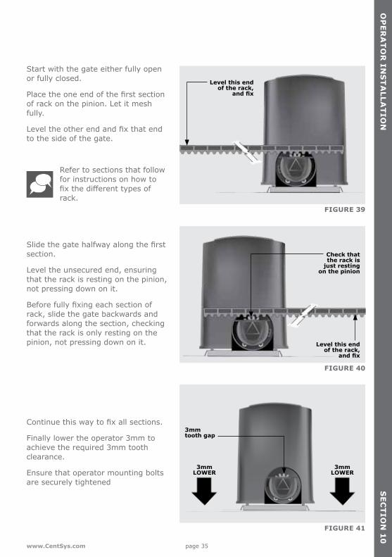
Start with the gate either fully open or fully closed.
Placetheoneendofthefirstsectionof rack on the pinion. Let it mesh fully.
Leveltheotherendandfixthatendto the side of the gate.
Slidethegatehalfwayalongthefirstsection.
Level the unsecured end, ensuring that the rack is resting on the pinion, not pressing down on it.
Beforefullyfixingeachsectionofrack, slide the gate backwards and forwards along the section, checking that the rack is only resting on the pinion, not pressing down on it.
Continuethiswaytofixallsections.
Finally lower the operator 3mm to achieve the required 3mm tooth clearance.
Ensure that operator mounting bolts are securely tightened
Refer to sections that follow for instructions on how to fixthedifferenttypesofrack.
Level this endof the rack,
and fix
Level this endof the rack,
and fix
Check thatthe rack is
just restingon the pinion
3mmLOWER
3mmLOWER
3mmtooth gap

page 36 www.CentSys.com
OP
ER
AT
OR
IN
ST
ALL
AT
ION
SE
CT
ION
10 FIGURE 29.
FIGURE 44
FIGURE 42
FIGURE 43
10.4.1. Steel rack
Fit the rack using the steel angle brackets provided.
Brackets must be spaced no more than 300mm apart.
Whenjoiningthedifferentlengthsofsteel rack, a simple way of ensuring correct pitch spacing, is to clamp asmalloff-cutbetweenthetwopieces.
10.4.2. RAZ rack
Fix the RAZ rack to the side of the gate using the TEK Screws provided. Use the vertical slots in order to allow for adjustment.
Use at least three TEK screws per half metre section of rack.
±300mm
±300mm
RAZ rackTEK screw
(Self drilling and tapping)

page 37www.CentSys.com
OP
ER
AT
OR
INS
TA
LLAT
ION
SE
CT
ION
10
FIGURE 29.
FIGURE 47
FIGURE 45
FIGURE 46
WhenfittingRAZrackitiseasiertostart on the right and work towards the left.
RAZ rack simply clips together.
10.4.3. Nylon Angle rack
Fix the rack to the side of the gate using the TEK screws provided.
Ensure that all the mounting holes provided in the angle section are used
Fit additional fixing screws through the horizontal slots to secure the rack to the gate directly above the pinion when the gate is in the closed, pedestrian and open positions.
Start on the right
Gateclosed
Pedestrianopening
Gateopen
TEK screw (Self drilling and tapping screw)
Use allmounting holes
Nylon angle rack
page 38 www.CentSys.com
OP
ER
AT
OR
IN
ST
ALL
AT
ION
SE
CT
ION
10
FIGURE 29.
FIGURE 50
FIGURE 48
FIGURE 49
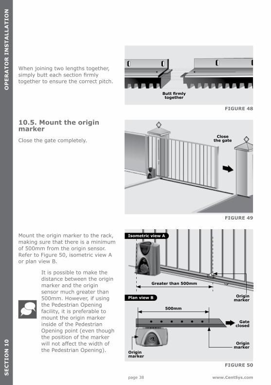
When joining two lengths together, simplybutteachsectionfirmlytogether to ensure the correct pitch.
10.5. Mount the origin markerClose the gate completely.
Mount the origin marker to the rack, making sure that there is a minimum of 500mm from the origin sensor. Refer to Figure 50, isometric view A or plan view B.
It is possible to make the distance between the origin marker and the origin sensor much greater than 500mm. However, if using the Pedestrian Opening facility, it is preferable to mount the origin marker inside of the Pedestrian Opening point (even though the position of the marker willnotaffectthewidthofthe Pedestrian Opening).
Butt firmlytogether
Closethe gate
500mm
Greater than 500mm
Origin marker
Origin marker
Isometric view A
Plan view B
Gateclosed
Origin marker

page 39www.CentSys.com
OP
ER
AT
OR
INS
TA
LLAT
ION
SE
CT
ION
10
For the steel rack, mount the origin marker onto the rack using the bracket provided.
Weld the bracket to the rack.
Bolt the origin marker onto the bracket using the fasteners provided.
FIGURE 29.
FIGURE 53
FIGURE 51
FIGURE 52
With RAZ rack the origin marker mounts directly on top of the rack without a bracket.
Drill mounting holes directly into the rack and bolt into position.
File away the front lip of the rack if you need to move the origin marker closer to the operator as the gate slides past.
With Nylon Angle rack it is necessary to use the bracket provided.
It is preferable to use self-tapping fasteners to secure the bracket into the side of the nylon rack as shown.
Make a small tack weld to secure the back of the bracket onto the angle iron section of the rack.
Bolt the origin marker onto the bracket using the fasteners provided
Bolt using fasteners provided
Origin marker bracket
Weld mounting bracket provided to steel rack
Steel rack
RAZ rack
Nylon angle rack
Bolt using fasteners provided
Origin marker bracket screw into side of the
nylon rack

page 40 www.CentSys.com
OP
ER
AT
OR
IN
ST
ALL
AT
ION
SE
CT
ION
10
Note the orientation of the origin marker.
FIGURE 54
FIGURE 55
Manually slide the gate open until the origin marker is in line with the origin sensor.
Ensure distance between the face of marker and front face of the sensor is between 13mm and 20mm.
Adjust distance by sliding the origin marker along the slotted mounting holesuntilthespecifieddistanceisachieved.
With Nylon Angle rack it is necessary to use the bracket provided.
For best results keep gap between marker and sensor as small as possible.
Gate
Rack
Gate
Rack
Origin marker
Origin sensor
13-20mm

page 41www.CentSys.com
10.6. Apply warning decalApply the supplied warning decals to both sides of the gate as indicated in the second drawing on the reverse side of the decal.
OP
ER
AT
OR
INS
TA
LLAT
ION
SE
CT
ION
10
FIGURE 56
1
2

page 42 www.CentSys.com
ELE
CT
RIC
AL
SE
TU
P
11. Electrical Setup
SE
CT
ION
11
1. Always check that the circuit breaker in the electrical panel is in the OFF position, and that all high-voltage circuits (more than 42.4V) are completely isolated from the mains supply before doing any work.
2. Ensure that all low-voltage systems (less than 42.4V) are suitably protected from damage, by disconnecting all sources of power such as chargers and batteries before doing any work.
3. All electrical work must be carried out according to the requirements of all applicable local electrical codes. (It is recommended that a licensed electrical contractor perform such work)
11.1. Connect all WiringConnect all cables as required to the control card, according to the wiring diagrams from page 43.
FIGURE 57
FIGURE 58
FIGURE 59
Check that the battery is connected to the controller. Refer to page 49.
Ensure that the battery polarity is correct.
Ensure that the controller is effectivelyearthedforimprovedlightning protection as shown on page 50.

page 43www.CentSys.com
ELE
CT
RIC
AL S
ET
UP
SE
CT
ION
11
FIGURE 60
Closing Safety Beam/Photocell
IRB Receiver
IRB Transmitter
12V/24V -
12V/24V -
12V/24V +
12V/24V +
COM
NC
NO
11.2 Wiring Diagram for Closing Safety Beams/ Photocells

page 44 www.CentSys.com
ELE
CT
RIC
AL
SE
TU
PS
EC
TIO
N 1
1
FIGURE 61
Opening Safety Beam/Photocell
IRB Receiver
IRB Transmitter
12V/24V -
12V/24V -
12V/24V +
12V/24V +
COM
NC
NO
11.3 Wiring Diagram for Opening Safety Beams/ Photocells
page 45www.CentSys.com
ELE
CT
RIC
AL S
ET
UP
SE
CT
ION
11
FIGURE 62
External radio receiver
Remote control circuitry
12V+
NEG
COM
NC
NO
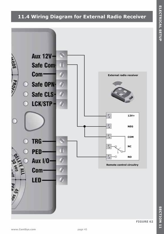
11.4 Wiring Diagram for External Radio Receiver

page 46 www.CentSys.com
ELE
CT
RIC
AL
SE
TU
PS
EC
TIO
N 1
1
FIGURE 63
Holiday Lockout keyswitch/keypad(normally-closed)
Intercom pushbutton
(normally-open)
Pedestrian keyswitch/keypad
(normally-open)
Status LED
11.5 Wiring Diagram for Other Inputs

page 47www.CentSys.com
ELE
CT
RIC
AL S
ET
UP
SE
CT
ION
11
FIGURE 64
E
N
L
90V - 240VMains in
Pillar Light/Courtesy Light1
1. Optional
Waterproofisolatorenclosurewithin one metreof motor
11.6 Wiring Diagram for Pillar Light to D2 Turbo

page 48 www.CentSys.com
ELE
CT
RIC
AL
SE
TU
P
FIGURE 65
E
N
L
90V - 240VMains in
Step-down transformer capable of supplyingthe controller with10V - 20V AC or 10V - 28V DC
SE
CT
ION
11
11.7 Wiring Diagram for Pillar Light to D2 Turbo Low-Voltage

page 49www.CentSys.com
Solar panel
12
V 0
- 3
0A
reg
ula
tor
Battery
Bat
tery
Pan
elLo
ad
11.8 Wiring Diagram for Solar Panel to D2 Turbo
ELE
CT
RIC
AL S
ET
UP
SE
CT
ION
11
FIGURE 66

page 50 www.CentSys.com
FIGURE 67
11.9 Wiring Diagram for Solar Panel to D2 Turbo Low-Voltage
ELE
CT
RIC
AL
SE
TU
PS
EC
TIO
N 1
1

page 51www.CentSys.com
ELE
CT
RIC
AL S
ET
UP
SE
CT
ION
11
FIGURE 69
FIGURE 68
11.10 Mains Supply and Battery Connections
Mainssupply
Battery leads

page 52 www.CentSys.com
ELE
CT
RIC
AL
SE
TU
PS
EC
TIO
N 1
1
11.11 Earthing for Effective Lightning Protection
FIGURE 70
E N L
90V - 240VMains in
Earth spike(>1m copper rodhammered into
the ground)
Optional40kAsurge
arrestor
Spadeconnector

page 53www.CentSys.com
CO
MM
ISS
ION
ING
TH
E S
YS
TE
MS
EC
TIO
N 1
2
12. Commissioning the System
IntroductionThe D2 Turbo and D2 Turbo Low-Voltage sliding gate operators’ advanced functions are controlled by intelligent microcontroller-based electronic controllers. These systems’ features and functions are enabled and disabled using the two user-friendly setting dials, with the top dial used for selecting the desired function, and the bottom dial used for selectingthespecificsettingtobeenabledordisabled.
Setting up the gate LimitsEnsure that the gate is in the fully closed position and the motor drive is engaged.
Rotate the Function Dial to the LIMITS position along the ‘A’ row of options.
Rotate the Setting Dial to the SETUP position along the ‘A’ row of options.
Press the pushbutton to select this feature.
FIGURE 71
FIGURE 72
FIGURE 73
Closethe gate

page 54 www.CentSys.com
CO
MM
ISS
ION
ING
TH
E S
YS
TE
MS
EC
TIO
N 1
2
The gate will then run through its automated procedure to determine the gate’s open and closed positions. If Setup is successful, the status LED will be green, which indicates that Setuphasfinished.
Return the Function Dial to the RUN position.
FIGURE 75
FIGURE 74

page 55www.CentSys.com
FIGURE 76. D2 TURBO CONTROLLER (ORANGE)
FIGURE 77. D2 TURBO LOW-VOLTAGE CONTROLLER (DARK GREEN)
13. Features and Functions
Functional Dial
Functional Dial
Select / Toggle pushbutton
Select / Toggle pushbutton
Settings Dial
Settings Dial
FEA
TU
RE
S A
ND
FUN
CT
ION
SS
EC
TIO
N 1
3

page 56 www.CentSys.com
FEA
TU
RE
S A
ND
FU
NC
TIO
NS
SE
CT
ION
13
Gate operationFull Gate Opening
The remote controls supplied with the D2 Turbo are used to operate the gate.
However, most automatic gate installationsarealsofittedwithan intercom which provides for communication between the house or building and the gate. Thehandsetisusuallyfittedwitha gate pushbutton which, when pressed, sends a signal to the D2 Turbo controller to operate the gate.
FIGURE 78
Modes of Operation
To operate the gate to open fully, the D2 Turbo has three modes to choose from depending on the application. Only one mode can be selected at any given time.
Standard Mode
Standard Mode is the most commonly used mode for domestic applications as it allows full control of the gate. Press the remote control button for approximately one second to set the gate in motion. If the remote control button is pressed while the gate is moving, the gate will stop. Press the remote control button again and the gate will go into reverse.
Autoclose, explained on page 57 and PIRAC (Beam/photocell Autoclose) on page 63, can be used with Standard Mode.
Open Only Mode
This mode is ideal for increased safety in multi-user, single dwelling applications.
If you select Open Only Mode, your gate will open when you press the button of the remote control or the gate pushbutton on the intercom – but pressing the button again while the gate is opening will be ignored. It will not cause the gate to stop or to reverse. Only the internal Autoclose feature described on page 57 of this installation manual, which is automatically enabled, will close the gate if you have selected Open Only Mode.
If the button of the remote control or intercom gate release is pressed while the gate is closing, the gate will immediately reopen. The gate cannot be stopped in a midway position and will therefore always close. If the button is pressed while the gate is in the open position, the Autoclose timer (page 57) will be reset.
page 57www.CentSys.com
FEA
TU
RE
S A
ND
FUN
CT
ION
SS
EC
TIO
N 1
3
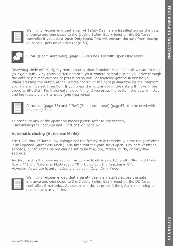
We highly recommend that a pair of Safety Beams are installed across the gate entrance and connected to the Closing Safety Beam input on the D2 Turbo controller if you select Open Only Mode. This will prevent the gate from closing on people, pets or vehicles (page 59).
PIRAC (Beam Autoclose) (page 63) can be used with Open Only Mode.
ReversingModeoffersslightlymoresecuritythanStandardModeasitallowsyoutocloseyour gate quickly by pressing, for instance, your remote control just as you drive through the gate to prevent children or pets running out - or anybody getting in behind you. When pressing the button of the remote control or the gate pushbutton on the intercom, your gate will be set in motion. If you press the button again, the gate will move in the opposite direction. So, if the gate is opening and you press the button, the gate will stop and immediately start to close (and vice versa).
Autoclose (page 57) and PIRAC (Beam Autoclose) (page63) can be used with Reversing Mode.
Toconfigureanyoftheoperatingmodespleaserefertothesection, ‘Customising the Features and Functions’ on page 67
Automatic closing (Autoclose Mode)
The D2 Turbo/D2 Turbo Low-Voltage has the facility to automatically close the gate after ithasopened(AutocloseMode).Thetimethatthegatestaysopenisbydefaultfifteenseconds,butthistimeperiodcanbesettobefive,ten,fifteen,thirty,orforty-fiveseconds.
As described in the previous section, Autoclose Mode is selectable with Standard Mode (page74)andReversingMode(page78)-bydefaultthefunctionisOff. However, Autoclose is automatically enabled in Open Only Mode.
We highly recommended that a Safety Beam is installed across the gate entrance and connected to the Closing Safety Beam input on the D2 Turbo controller, if you select Autoclose in order to prevent the gate from closing on people, pets or vehicles.
page 58 www.CentSys.com
FEA
TU
RE
S A
ND
FU
NC
TIO
NS
SE
CT
ION
13
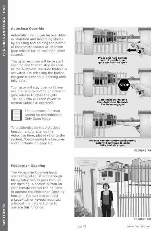
Autoclose Override
Automatic closing can be overridden in Standard and Reversing Modes by pressing and holding the button of the remote control or intercom gate release for no less than three seconds.
The gate response will be to start opening and then to stop as soon as the Autoclose Override feature is activated. On releasing the button, the gate will continue opening until fully open.
Your gate will stay open until you use the remote control or intercom gate release to close the gate. The D2 Turbo will then revert to normal Autoclose operation
FIGURE 79
FIGURE 80
The Autoclose function cannot be overridden in Only Open Mode.
To enable/disable the Autoclose function and/or change the Autoclose time, please refer to the section, ‘Customising the Features and Functions’ on page 67.
Pedestrian Opening
The Pedestrian Opening input opens the gate just wide enough for a pedestrian to pass through the opening. A second button on your remote control can be used to operate the Pedestrian Opening function. You can also connect a keyswitch or keypad mounted adjacent the gate entrance to operate this function.
Press and hold remote control pushbutton;
gate will start to open
Gate stops to indicate that Autoclose Override
has been engaged
Release remote control pushbutton; gate will continue to open
fully and stay open
page 59www.CentSys.com
FEA
TU
RE
S A
ND
FUN
CT
ION
SS
EC
TIO
N 1
3
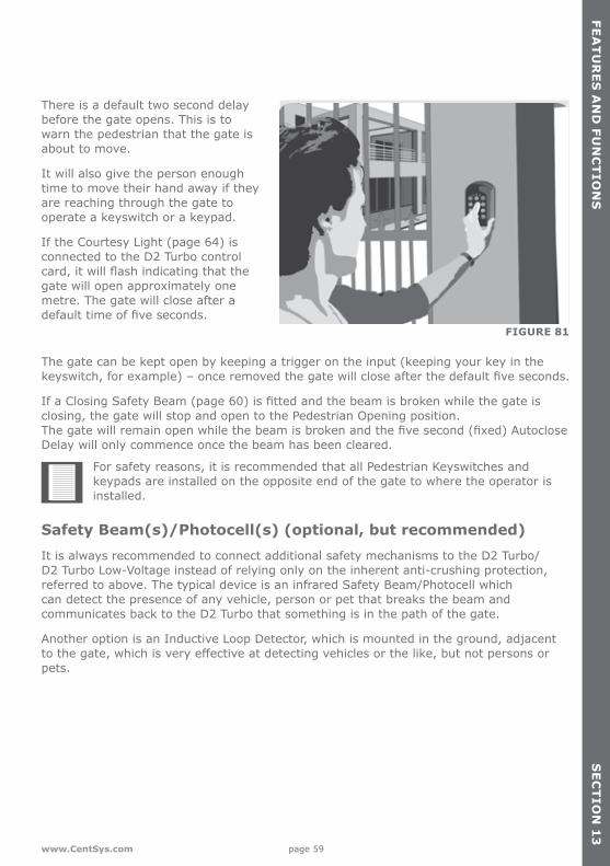
There is a default two second delay before the gate opens. This is to warn the pedestrian that the gate is about to move.
It will also give the person enough time to move their hand away if they are reaching through the gate to operate a keyswitch or a keypad.
If the Courtesy Light (page 64) is connected to the D2 Turbo control card,itwillflashindicatingthatthegate will open approximately one metre. The gate will close after a defaulttimeoffiveseconds.
FIGURE 81
The gate can be kept open by keeping a trigger on the input (keeping your key in the keyswitch,forexample)–onceremovedthegatewillcloseafterthedefaultfiveseconds.
IfaClosingSafetyBeam(page60)isfittedandthebeamisbrokenwhilethegateisclosing, the gate will stop and open to the Pedestrian Opening position. Thegatewillremainopenwhilethebeamisbrokenandthefivesecond(fixed)AutocloseDelay will only commence once the beam has been cleared.
For safety reasons, it is recommended that all Pedestrian Keyswitches and keypads are installed on the opposite end of the gate to where the operator is installed.
Safety Beam(s)/Photocell(s) (optional, but recommended)It is always recommended to connect additional safety mechanisms to the D2 Turbo/D2 Turbo Low-Voltage instead of relying only on the inherent anti-crushing protection, referred to above. The typical device is an infrared Safety Beam/Photocell which can detect the presence of any vehicle, person or pet that breaks the beam and communicates back to the D2 Turbo that something is in the path of the gate.
Another option is an Inductive Loop Detector, which is mounted in the ground, adjacent tothegate,whichisveryeffectiveatdetectingvehiclesorthelike,butnotpersonsorpets.

page 60 www.CentSys.com
FEA
TU
RE
S A
ND
FU
NC
TIO
NS
SE
CT
ION
13
Closing Safety Beams
Closing Safety Beams provide additional protection against your gate closing on people or vehicles.
If the beam is broken while the gate is opening, the gate will continue to open.
If the gate is open, the gate cannot be closed if the beam is broken, and if the gate is closing when the beam is broken, it will stop and re-open.
FIGURE 82
FIGURE 83
If you select the Autoclose (page 74) feature, the gate will remain open if the beam is broken and it will only close after the set Autoclose time has expired when the beam has been cleared.
Please contact us for more information on suitable protection devices.
Opening Safety Beams
These beams prevent your gate from opening if an object, person or pet is in the way.
If the beam is broken while the gate is closed, the gate will not open. If the gate is opening and the beams are broken, it will stop then close. If the gate is closing while the beams are broken, it will continue to close
Gate closed - gate cannot openGate opening - gate stops and re-closes
Gate closing - gate continues closing
page 61www.CentSys.com
FEA
TU
RE
S A
ND
FUN
CT
ION
SS
EC
TIO
N 1
0
FIGURE 84
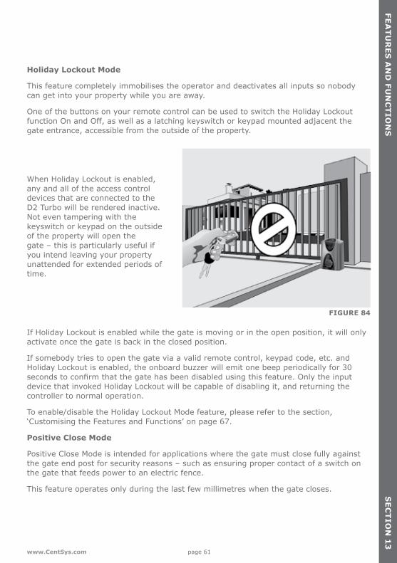
Holiday Lockout Mode
This feature completely immobilises the operator and deactivates all inputs so nobody can get into your property while you are away.
One of the buttons on your remote control can be used to switch the Holiday Lockout functionOnandOff,aswellasalatchingkeyswitchorkeypadmountedadjacentthegate entrance, accessible from the outside of the property.
When Holiday Lockout is enabled, any and all of the access control devices that are connected to the D2 Turbo will be rendered inactive. Not even tampering with the keyswitch or keypad on the outside of the property will open the gate – this is particularly useful if you intend leaving your property unattended for extended periods of time.
If Holiday Lockout is enabled while the gate is moving or in the open position, it will only activate once the gate is back in the closed position.
If somebody tries to open the gate via a valid remote control, keypad code, etc. and Holiday Lockout is enabled, the onboard buzzer will emit one beep periodically for 30 secondstoconfirmthatthegatehasbeendisabledusingthisfeature.Onlytheinputdevice that invoked Holiday Lockout will be capable of disabling it, and returning the controller to normal operation.
To enable/disable the Holiday Lockout Mode feature, please refer to the section, ‘Customising the Features and Functions’ on page 67.
Positive Close Mode
Positive Close Mode is intended for applications where the gate must close fully against the gate end post for security reasons – such as ensuring proper contact of a switch on the gate that feeds power to an electric fence.
This feature operates only during the last few millimetres when the gate closes. SE
CT
ION
13
page 62 www.CentSys.com
FEA
TU
RE
S A
ND
FU
NC
TIO
NS
SE
CT
ION
13
Itisrecommendedthatarubberstripbefixedtothefrontedgeofthegatetoreduce the noise when the gate closes against the end post
To enable / disable the Positive Close Mode feature, please refer to the section, ‘Customising the Features and Functions’ on page 67.
Speed Profiles
The D2 Turbo can be set to run in either a High Speed Mode (default) which is approximately 24 metres per minute, or a Low Speed Mode which is approximately 16 metres per minute.
Highspeedsofferagreaterlevelofconvenienceandsecurity,whileslowerspeedsensureincreased levels of safety at the gate.
TochangetheSpeedProfile,pleaserefertothesection,‘CustomisingtheFeaturesandFunctions’ on page 67.
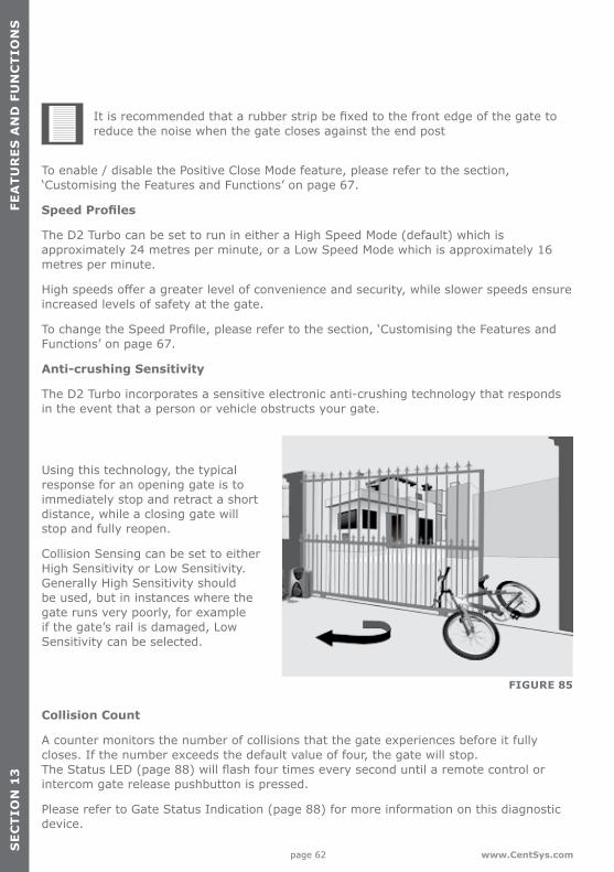
Anti-crushing Sensitivity
The D2 Turbo incorporates a sensitive electronic anti-crushing technology that responds in the event that a person or vehicle obstructs your gate.
Using this technology, the typical response for an opening gate is to immediately stop and retract a short distance, while a closing gate will stop and fully reopen.
Collision Sensing can be set to either High Sensitivity or Low Sensitivity. Generally High Sensitivity should be used, but in instances where the gate runs very poorly, for example if the gate’s rail is damaged, Low Sensitivity can be selected.
Collision Count
A counter monitors the number of collisions that the gate experiences before it fully closes. If the number exceeds the default value of four, the gate will stop. TheStatusLED(page88)willflashfourtimeseveryseconduntilaremotecontrolorintercom gate release pushbutton is pressed.
Please refer to Gate Status Indication (page 88) for more information on this diagnostic device.
FIGURE 85

page 63www.CentSys.com
FEA
TU
RE
S A
ND
FUN
CT
ION
SS
EC
TIO
N 1
3
PIRAC
With PIRAC Mode enabled, your gate will close as soon as you have driven through and passed the Safety Beams – giving intruders no time to follow behind you.
FIGURE 86
FIGURE 87
FIGURE 88
If Autoclose is enabled and the gate has been opened but nothing moves through the Closing Safety Beam, the gate will stay fully open for the duration of the Autoclose timer before closing. However, if something passes through the Closing Beam the gate will close immediately.
If something crosses the beam while the gate is opening, the gate will continue to open until the beam is cleared. Once the beam is cleared, the gate will stop and close. If the gate has reached its fully open position, it will stop and remain open until the beam is cleared.
To enable/disable PIRAC Mode, please refer to the section, ‘Customising the Features and Functions’ on page 65.
Gateopening
Gateopening
Gateclosing
Beam
Beam
Beam
page 64 www.CentSys.com
FEA
TU
RE
S A
ND
FU
NC
TIO
NS
SE
CT
ION
13
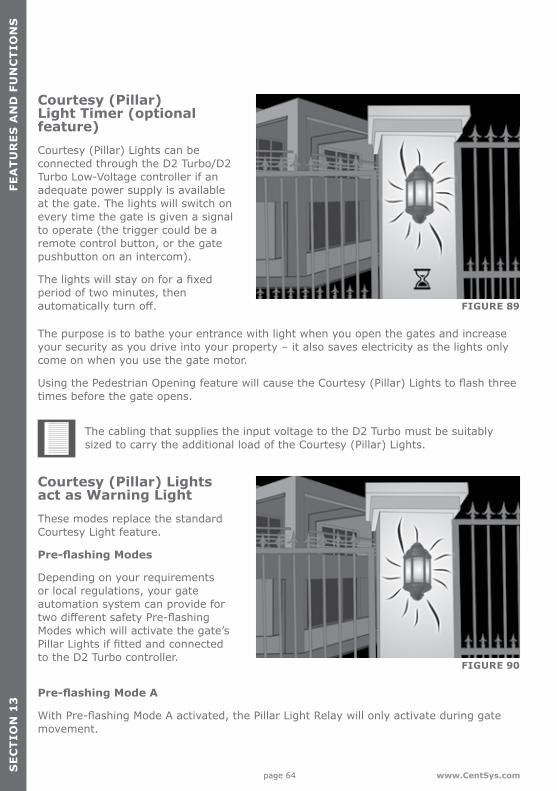
Courtesy (Pillar) Light Timer (optional feature)Courtesy (Pillar) Lights can be connected through the D2 Turbo/D2 Turbo Low-Voltage controller if an adequate power supply is available at the gate. The lights will switch on every time the gate is given a signal to operate (the trigger could be a remote control button, or the gate pushbutton on an intercom).
Thelightswillstayonforafixedperiod of two minutes, then automaticallyturnoff. FIGURE 89
FIGURE 90
The purpose is to bathe your entrance with light when you open the gates and increase your security as you drive into your property – it also saves electricity as the lights only come on when you use the gate motor.
UsingthePedestrianOpeningfeaturewillcausetheCourtesy(Pillar)Lightstoflashthreetimes before the gate opens.
The cabling that supplies the input voltage to the D2 Turbo must be suitably sized to carry the additional load of the Courtesy (Pillar) Lights.
Courtesy (Pillar) Lights act as Warning LightThese modes replace the standard Courtesy Light feature.
Pre-flashing Modes
Depending on your requirements or local regulations, your gate automation system can provide for twodifferentsafetyPre-flashingModes which will activate the gate’s PillarLightsiffittedandconnectedto the D2 Turbo controller.
Pre-flashing Mode A
WithPre-flashingModeAactivated,thePillarLightRelaywillonlyactivateduringgatemovement.
page 65www.CentSys.com
FEA
TU
RE
S A
ND
FUN
CT
ION
SS
EC
TIO
N 1
3
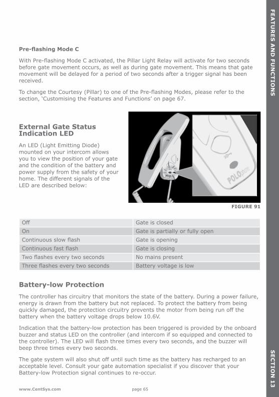
FIGURE 91
Pre-flashing Mode C
WithPre-flashingModeCactivated,thePillarLightRelaywillactivatefortwosecondsbefore gate movement occurs, as well as during gate movement. This means that gate movement will be delayed for a period of two seconds after a trigger signal has been received.
TochangetheCourtesy(Pillar)tooneofthePre-flashingModes,pleaserefertothesection, ‘Customising the Features and Functions’ on page 67.
External Gate Status Indication LED An LED (Light Emitting Diode) mounted on your intercom allows you to view the position of your gate and the condition of the battery and power supply from the safety of your home.ThedifferentsignalsoftheLED are described below:
Off Gate is closedOn Gate is partially or fully openContinuousslowflash Gate is openingContinuousfastflash Gate is closingTwoflasheseverytwoseconds No mains presentThreeflasheseverytwoseconds Battery voltage is low
Battery-low ProtectionThe controller has circuitry that monitors the state of the battery. During a power failure, energy is drawn from the battery but not replaced. To protect the battery from being quicklydamaged,theprotectioncircuitrypreventsthemotorfrombeingrunoffthebattery when the battery voltage drops below 10.6V.
Indication that the battery-low protection has been triggered is provided by the onboard buzzer and status LED on the controller (and intercom if so equipped and connected to thecontroller).TheLEDwillflashthreetimeseverytwoseconds,andthebuzzerwillbeep three times every two seconds.
Thegatesystemwillalsoshutoffuntilsuchtimeasthebatteryhasrechargedtoanacceptable level. Consult your gate automation specialist if you discover that your Battery-low Protection signal continues to re-occur.

page 66 www.CentSys.com
FEA
TU
RE
S A
ND
FU
NC
TIO
NS
SE
CT
ION
13
Solar ProfileD2 Turbo and D2 Turbo Low-Voltage controllers manufactured after August 2014 support Solar Mode.
Thisusefulprofileoptionallowsthemainsfailcircuitrytobebypassedininstanceswheresolar power is being used in lieu of an electrical mains supply. The standard response of the controller upon detecting a mains failure is to emit two short beeps every two secondsbut,iftheSolarProfilehasbeenselected,theconditionwillnotbeflagged.
To enable/disable Solar Mode, please refer to the section ‘Customising the Features and Functions’ on page 67.

page 67www.CentSys.com
CU
ST
OM
ISIN
G T
HE
FEA
TU
RE
S A
ND
FUN
CT
ION
SS
EC
TIO
N 1
4
FIGURE 92
FIGURE 93
FIGURE 94
Please always adjust the Function Dialfirst.
Set this to the desired function, and then move the Setting Dial to the preferred setting.
Ifasettingisforasinglefixedvalue,for example, 15 second Autoclose time, then the Select pushbutton acts as a select for that single choice.
However, if the setting has two options,forexampleOn/OfforHi/Lo, then the pushbutton acts as a toggle between the two preferences.
14. Customising the Features and Functions
Simplicity is the ultimate sophistication’. ~ Leonardo Da Vinci
The D2 Turbo and D2 Turbo Low-Voltage controllers make ordinarily complex settings as quick and easy as possible. Using the Function and Setting Dials, the Select/Toggle pushbutton, and the bi-colour (red and green) Status LED you can set up the many featuresandfunctionsinaflash.
Function Dial
Setting Dial

page 68 www.CentSys.com
CU
ST
OM
ISIN
G T
HE
FE
AT
UR
ES
AN
D F
UN
CT
ION
SS
EC
TIO
N 1
4
FIGURE 95
FIGURE 96
FIGURE 97
When using the Select pushbutton to toggle between preferences, the status LED will light up as green to indicate On or High; or alternatively redtoindicateOfforLow.
The Function Dial must always be returned to the Run position (rotated fully counter-clockwise) after youhavefinishedsettingupany of the features, modes orprofiles.Thisensuresthat it will be ready for use.
Remote control administrationThe D2 Turbo controllers incorporate an onboard multichannel receiver compatible with code-hopping technology.
The receiver will allow any combinationofthedifferentinputs-Trigger (Gate fully open), Pedestrian, Holiday Lockout, etc. to be operated from a single multi-button remote control.

page 69www.CentSys.com
CU
ST
OM
ISIN
G T
HE
FEA
TU
RE
S A
ND
FUN
CT
ION
SS
EC
TIO
N 1
4
FIGURE 98
Youcanalsoartificiallyincreasethe number of buttons by using a two-button combination. One of the buttons is used as a Shift button to allow the other buttons to be used again in combination with this button. Press and hold the allocated Shift button and then press one of the other buttons to create a new button. The Shift button cannot be used as a button on its own - it must always be used in combination with another button.
Use of the Shift button principle allows a three-button transmitter to gain an extra button and operate four functions and a four-button transmitter gains two extra buttons and can operate six functions. This is quite handy if you’d like to control additional devices from a single multi-button remote control, for example your garage doors if they are equipped with compatible code-hopping receivers.
However, it’s important to note that the other devices cannot be activated with the new Shift button, only the D2 Turbo (and other operators that are equipped with an onboard receiver) is able to recognise the Shift button signals.
Using the shift key principle also prevents you from enabling functions like Holiday Lockout Mode by accident. This is because you have to use both hands to press the two-button combination.
At any stage remote controls can be selectively added or deleted within the system. To selectively delete a remote control, the remote control must be available. Pleaserefertothesection,‘DeletingSpecificRemoteControls’onpage71.
5
6
1 2
3
4
Press andhold the
‘fourth’ buttonas a Shift button
together withbutton 1, 2 or
3 to operate 4, 5 or 6
Shift button
Shift button

page 70 www.CentSys.com
CU
ST
OM
ISIN
G T
HE
FE
AT
UR
ES
AN
D F
UN
CT
ION
SS
EC
TIO
N 1
4
Adding code-hopping remote controls To add a code-hopping remote control to the onboard receiver andassignabuttontoanyspecificfunction as described above, please follow the steps below:
Step 1: Rotate the Function Dial to the REMOTES position (B).
Step 2: Rotate the Setting Dial to the desired selection along the ‘B’ row of options. FIGURE 99
FIGURE 100
You can choose from the following settings:• Tx TRG to assign a remote control button to be learned into the system and
trigger the gate to fully open• Tx PED to assign a remote control button to be learned into the system and
partially open the gate for a pedestrian• Tx LCK to assign a remote control button to be learned into the system and
activate Holiday Lockout Mode
Step 3: Press the pushbutton to select the setting chosen from above – the Status LED will change from redtogreentoconfirmthesetting.

page 71www.CentSys.com
CU
ST
OM
ISIN
G T
HE
FEA
TU
RE
S A
ND
FUN
CT
ION
SS
EC
TIO
N 1
4
FIGURE 101
FIGURE 102
FIGURE 103
Step 4: Press the desired button on the remote control(s) that you want to activate the selected function.
TheStatusLEDwillflashtwiceindicating that the onboard receiver has learned in the remote control(s). The onboard buzzer will also pulse twice.
Step 5: Return the Function Dial to the RUN position.
Deleting specific remote controlsTodeletespecificremotecontrolsfromtheD2Turbo’sonboardreceiver,pleasefollowthesteps below:
Step 1: Rotate the Function Dial to the REMOTES position (B).
Step 2: Rotate the Setting Dial to DELETE Tx along the ‘B’ row of options.Thiswilldeletespecificremote controls from the onboard receiver’s memory.

page 72 www.CentSys.com
CU
ST
OM
ISIN
G T
HE
FE
AT
UR
ES
AN
D F
UN
CT
ION
SS
EC
TIO
N 1
4
FIGURE 104
FIGURE 105
FIGURE 106
Step 3: Press the pushbutton to select – the Status LED will change from red to green.
Step 4: Press any button on the specificremotecontrol(s)thatyouwant to delete from the onboard receiver’s memory. The Status LED willflashgreenthreetimesandthebuzzer will also beep three times indicating that the onboard receiver has deleted the remote control(s) from its memory.
Step 5: Return the Function Dial to the RUN position.

page 73www.CentSys.com
CU
ST
OM
ISIN
G T
HE
FEA
TU
RE
S A
ND
FUN
CT
ION
SS
EC
TIO
N 1
4
FIGURE 107
FIGURE 108
FIGURE 109
Deleting all remote controlsTo delete all the learned-in remote controls from the D2 Turbo onboard receiver, please follow the steps below:
Step 1: Rotate the Function Dial to the REMOTES position (B).
Step 2: Rotate the Setting Dial to DELETE ALL along the ‘B’ row of options. This will delete all remote controls from the onboard receiver’s memory.
Step 3: Press the pushbutton to select the setting.
TheStatusLEDwillinitiallyflashred. Hold down the pushbutton until the Status LED turns green and three beeps are heard. This will indicate that the onboard receiver has deleted the remote control(s) from its memory.
Step 4: Return the Function Dial to the RUN position.

page 74 www.CentSys.com
CU
ST
OM
ISIN
G T
HE
FE
AT
UR
ES
AN
D F
UN
CT
ION
SS
EC
TIO
N 1
4
FIGURE 110
FIGURE 111
FIGURE 112
Setting the Autoclose featureTheAutoclosefeaturecanbeselectedtobeeitherOfforActivated,withapre-selectedtime delay.
Activating the Autoclose feature
To activate the Autoclose, with a pre-selected time delay, please follow the steps below:
Step 1: Rotate the Function Dial to the AUTOCLOSE position (C).
Step 2: Rotate the Setting Dial to the desired time delay setting along the ‘C’ row of options. You can choose either 5 seconds, 10 seconds, 15 seconds, 30 seconds or 45 seconds.
Step 3: Press the pushbutton to select your choice.
The Status LED will change from red to green indicating that the Autoclose feature has been activated with the delay time selected in Step 2.

page 75www.CentSys.com
CU
ST
OM
ISIN
G T
HE
FEA
TU
RE
S A
ND
FUN
CT
ION
SS
EC
TIO
N 1
4
Deactivating the Autoclose feature
To deactivate the Autoclose feature, please follow the steps below:
Step 1: Rotate the Function Dial to the AUTOCLOSE position (C).
Step 2: Rotate the Setting Dial to the OFF selection along the ‘C’ row of options. The Status LED will be red if Autoclose is on. If it is already Off,theStatusLEDwillbegreen.
FIGURE 113
FIGURE 114
FIGURE 115
Step 4: Return the Function Dial to the RUN position.
Please note that if the operator is running Open Only Mode – the Autoclose feature is activated with a 15 second delay as the default – this can be changed if necessary.
Step 3: Press the pushbutton to select.
The Status LED will change from red to green indicating that the Autoclose feature has been deactivatedorswitchedOff.

page 76 www.CentSys.com
CU
ST
OM
ISIN
G T
HE
FE
AT
UR
ES
AN
D F
UN
CT
ION
SS
EC
TIO
N 1
4
FIGURE 116
FIGURE 117
FIGURE 118
Step 4: Return the Function Dial to the RUN position.
Setting the Mode of OperationThe D2 Turbo has three modes to choose from depending on the application. Only one mode can be selected at any given time
Step 1: Rotate the Function Dial to the AUTOCLOSE position (C).
Step 2: Rotate the Setting Dial to the OFF selection along the ‘C’ row of options. The Status LED will be red if Autoclose is on. If it is already Off,theStatusLEDwillbegreen.
Step 3: Press the pushbutton to select.
The Status LED will change from red to green indicating that the Autoclose feature has been deactivatedorswitchedOff.

page 77www.CentSys.com
CU
ST
OM
ISIN
G T
HE
FEA
TU
RE
S A
ND
FUN
CT
ION
SS
EC
TIO
N 1
4
FIGURE 119
FIGURE 120
FIGURE 121
Open Only Mode
To activate Open Only Mode please follow these steps:
Step 1: Rotate the Function Dial to the MODE position (D).
Step 2: Rotate the Setting Dial to the OPEN ONLY selection along the ‘D’ row of options.
Step 4: Return the Function Dial to the RUN position.
Please note that PIRAC Mode can be active in addition to this mode if so desired.
Step 3: Press the pushbutton to select the setting.
The Status LED will change from red to green indicating that the Open Only Operating Mode has been activated.

page 78 www.CentSys.com
CU
ST
OM
ISIN
G T
HE
FE
AT
UR
ES
AN
D F
UN
CT
ION
SS
EC
TIO
N 1
4
Step 4: Return the Function Dial to the RUN position.
Please note that PIRAC Mode can be active in addition to this mode if so desired.
FIGURE 123
FIGURE 122
FIGURE 124
Reversing Mode
To activate Reversing Mode, please follow the steps below:
Step 1: Rotate the Function Dial to the MODE position (D).
Step 2: Rotate the Setting Dial to the REVERSING selection along the ‘D’ row of options.
Step 3: Press the pushbutton to select the setting.
The Status LED will change from red to green indicating that the Reversing Operating Mode has been activated.

page 79www.CentSys.com
CU
ST
OM
ISIN
G T
HE
FEA
TU
RE
S A
ND
FUN
CT
ION
SS
EC
TIO
N 1
4
Step 4: Return the Function Dial to the RUN position.
Please note that PIRAC Mode can be active in addition to this mode if so desired.
FIGURE 126
FIGURE 125
FIGURE 127
Setting PIRAC ModePIRAC (Beam Autoclose) Mode can be activated when using any of the three Operating Modes (Standard, Open Only, or Reversing).
To select PIRAC Mode as either On or Off,pleasefollowthestepsbelow:
Step 1: Rotate the Function Dial to the MODE position (D).
Step 2: Rotate the Setting Dial to the PIRACon/offselectionalongthe‘D’row of options.
Step 3: Press the pushbutton to select the setting.
The Status LED will change from red to green indicating that PIRAC Mode has been activated, or it will change to red indicating that PIRAC Mode has been deactivated.

page 80 www.CentSys.com
CU
ST
OM
ISIN
G T
HE
FE
AT
UR
ES
AN
D F
UN
CT
ION
SS
EC
TIO
N 1
4
Step 4: Return the Function Dial to the RUN position.
FIGURE 128
FIGURE 129
FIGURE 130
Setting the Pre-flashing ModesPre-flashingModeAandPre-flashingModeCcanbeactivatedinadditiontoanyoftheabove Modes of Operation.
ToselectaPre-flashingModeaseitheronoroff,pleasefollowthesteps below:
Step 1: Rotate the Function Dial to the MODE position (D).
Step 2: Rotate the Setting Dial to eitherPFAon/offforPre-flashModeA,orPFCon/offforPre-flashModeC along the ‘C’ row of options.
Step 3: Press the pushbutton to togglethePre-flashModebetweenOnandOff.
The Status LED will change from red to green indicating that the selected Pre-flashModehasbeenactivated,or it will change to red indicating that it has been deactivated.

page 81www.CentSys.com
CU
ST
OM
ISIN
G T
HE
FEA
TU
RE
S A
ND
FUN
CT
ION
SS
EC
TIO
N 1
4
Step 4: Return the Function Dial to the RUN position.
FIGURE 131
FIGURE 132
FIGURE 133
Setting the Operating ProfilesThreeOperatingProfiles,PositiveCloseMode,SpeedandCollisionSensitivity,caneachbeconfigureddependingonyourindividualrequirements.
Positive Close Mode
To activate or deactivate Positive Close Mode, please follow the steps below:
Step 1: Rotate the Function Dial to the PROFILE position (E).
Step 2: Rotate the Setting Dial toPCMon/offalongthe‘E’rowofoptions.
Step 3: Press the pushbutton to toggle the chosen mode between On andOff.
The Status LED will change from red to green indicating that the selected Positive Close Mode has been activated, or it will change to red indicating that it has been deactivated.

page 82 www.CentSys.com
CU
ST
OM
ISIN
G T
HE
FE
AT
UR
ES
AN
D F
UN
CT
ION
SS
EC
TIO
N 1
4
Step 4: Return the Function Dial to the RUN position.
FIGURE 134
FIGURE 135
FIGURE 136
Setting the Speed Profile to High or LowToselectthedesiredspeedprofile,eitherHigh(approximately24m/min)orLow(approximately 16m/min) please follow the steps below:
Step 1: Rotate the Function Dial to the PROFILE position (E).
Step 2: Rotate the Setting Dial to SPEED hi/lo along the ‘E’ row of options.
Step 3: Press the pushbutton to toggleSpeedprofilebetweenHighand Low.
The Status LED will change from red to green indicating that the High SpeedProfilehasbeenactivated,or it will change to green indicating thattheLowSpeedProfilehasbeenactivated.

page 83www.CentSys.com
CU
ST
OM
ISIN
G T
HE
FEA
TU
RE
S A
ND
FUN
CT
ION
SS
EC
TIO
N 1
4
Step 4: Return the Function Dial to the RUN position.
FIGURE 137
FIGURE 138
FIGURE 139
Setting the Anti-crushing Sensitivity Profile To select the desired sensitivity of the anti-crushing technology as either High or Low, please follow the steps below:
Step 1: Rotate the Function Dial to the PROFILE position (E).
Step 2: Rotate the Setting Dial to SENS hi/lo along the ‘E’ row of options.
Step 3: Press the pushbutton to toggletheSensitivityProfilebetweenHigh and Low.
The Status LED will change from red to green indicating that the HighSensitivityProfilehasbeenactivated, or it will change to red indicating that the Low Sensitivity Profilehasbeenactivated.

page 84 www.CentSys.com
CU
ST
OM
ISIN
G T
HE
FE
AT
UR
ES
AN
D F
UN
CT
ION
SS
EC
TIO
N 1
4
Step 4: Return the Function Dial to the RUN position.
FIGURE 140
FIGURE 141
FIGURE 142
SolarToconfigurethecontrollerforsolarpower(controllersmanufacturedafterAugust2014only), please follow the steps below:
Step 1: Rotate the Function Dial to the PROFILE position (E).
Step 2: Rotate the Setting Dial to SOLARon/offalongthe‘E’rowofoptions.
Step 3: Press the pushbutton to toggletheSolarProfilebetweenOnandOff.
The Status LED will change from red to green indicating that the Solar Profilehasbeenactivated,oritwillchange to red indicating that it has been deactivated.

page 85www.CentSys.com
CU
ST
OM
ISIN
G T
HE
FEA
TU
RE
S A
ND
FUN
CT
ION
SS
EC
TIO
N 1
4
Step 4: Return the Function Dial to the RUN position.
FIGURE 143
Should you wish to verify your settings you can rotate the Function Dial to the function that you want to check the settings of. Then rotate the Setting Dial to the various selection options. The status LED will light up as green to indicate that the selected optioniseitherOnorHigh;oralternativelyredtoindicateOfforLow.
Reverting to Factory DefaultsIt is possible to clear and default the system completely, resetting all programmed settings to default values and clearing all learned remotes as well as gate limits.
To perform a complete reset:
• Remove power from the unit by disconnecting both the mains supply and one battery terminal
• Press and hold the pushbutton • Reapplypowertotheunit(itmakesnodifferencewhetherthebatteryormainsis
reconnectedfirst)• Release the pushbutton• The controller is now defaulted
Reverting to Factory Defaults
Parameter description Unit Minimum Default Maximum
Sensitivity Hi/Lo Lo Hi HiAutoclose status On/Off OffAutoclose timer s 15s Off 45sModes of Operation S, O, R SPIRAC On/Off OffPCM status On/Off OffSpeed Hi/Lo Lo Hi HiLightprofile CUR, PFA, PFC CUR
TABLE 2

page 86 www.CentSys.com
DE
SC
RIP
TIO
N O
F T
ER
MIN
AL
FUN
CT
ION
SS
EC
TIO
N 1
5
15. Description of Terminal Functions
Motor Motor output – connects to the Blue or Brown motor wire.
Motor Motor output – connects to the Blue or Brown motor wire.
Batt + Positive battery connection.
Battery terminal normally indicated as + or red (right-hand battery)
Batt - Negative battery connection.
Battery terminal normally indicated as - or black (right-hand battery)
COM The common termination point. All trigger signals, etc. have their return path to one of the COM terminals.
PED Pedestrian Opening input. (A normally-open potential-free input). Momentarily connecting this input to COM will cause the gate to open to the Pedestrian open position. For more information refer to the Pedestrian feature.
TRG Trigger input. (A normally-open potential-free input) Momentarily connecting this input to COM will cause the gate to open or close depending on the operating mode selected. For more information see the Autoclose feature and Modes of Operation.
LCK/STP Holiday Lockout or gate Stop input. (A normally-closed potential-free input). For as long as a connection between this input and COM is maintained the controller will behave normally. But, when this connection to COM is broken all inputs are inhibited and all triggers except the one that invoked the feature will be ignored, and if the gate is moving it will stop. As the name implies, this feature is mostly used in situations where the premises will be left uninhabited for a period of time, for example when the residents go away on holiday, and electronically locks the entire system for added security. While this is usually a remote control button, other typical devices include a pushbutton, keypad, keyswitch and any number of access control devices.
If this input is enabled while the gate is moving or in the open position, it will only activate and inhibit operation of all the inputs when the gate is back in the closed position
IftheLCKfunctionisnotrequiredalinkmustbefittedbetweenLCK and COM*(refer to note on page 80)
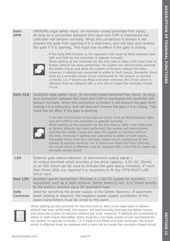
page 87www.CentSys.com
DE
SC
RIP
TIO
N O
F TE
RM
INA
L FUN
CT
ION
SS
EC
TIO
N 1
5
Safe OPN
OPENING edge safety input. (A normally-closed potential-free input). As long as a connection between this input and COM is maintained the controller will behave normally. When this connection is broken it will prevent the gate from opening if it is stationary, and will stop and reverse thegateifitisopening.Thisinputhasnoeffectifthegateisclosing.
IftheSafeOPNfunctionisnotrequiredalinkmustbefittedbetweensafeOPE and COM for the controller to operate normally.Whensettingupthecontrollerforthefirsttimeorafterafullresetbacktofactory default has been performed, the system will electronically override the Safety Inputs and allow the system to function without the links. However, if safeties are connected to either or both inputs, thereafter there must be a normally-closed circuit maintained for the system to operate correctly.I.e.ifbeamsarefittedandthenremoved,thecircuitwhichisaffectedmustbereplacedwithawirelinktocreatethenormally-closedcircuit.
Safe CLS CLOSING edge safety input. (A normally-closed potential-free input). As long as a connection between this input and COM is maintained the controller will behave normally. When this connection is broken it will prevent the gate from closing if it is stationary, and will stop and reverse the gate if it is closing. This inputhasnoeffectifthegateisopening.
IftheSafCLSfunctionisnotrequiredalinkmustbefittedbetweenSafeCLS and COM for the controller to operate normally. ) Whensettingupthecontrollerforthefirsttimeorafterafullresetbackto factory defaults has been performed, the system will electronically override the Safety Inputs and allow the system to function without the links. However, if safeties are connected to either or both inputs, thereafter there must be a normally-closed circuit maintained for the systemtooperatecorrectly.I.e.ifbeamsarefittedandthenremoved,thecircuitwhichisaffectedmustbereplacedwithawirelinktocreatethenormally-closed circuit.
LED External gate status indicator. (A low-current output signal.) An output terminal which provides a low-drive (approx. 4,5V DC, 20mA) to an LED which can be used to indicate the gate status remotely. If more thanthreeLEDsarerequireditisnecessarytofittheCP78MULTI-LEDdriver card.
Aux 12V Auxiliary power connection. Provides a +12V DC supply for auxiliary equipment such as a radio receiver, Safety Beam(s) etc. It is linked directly to the battery positive via a 3A resettable fuse.
Safe Common
Used for switching the power supply to the Safety Beam(s). If automatic beam testing is required, the negative power supply connection of the beam transmitters must be wired to this point.
Whensettingupthecontrollerforthefirsttimeorafterafullresetbacktofactorydefault has been performed, the system will electronically override the Safety Inputs and allow the system to function without the links. However, if safeties are connected to either or both inputs thereafter, there must be a normally-closed circuit maintained for thesystemtooperatecorrectly.I.e.ifbeamsarefittedandthenremoved,thecircuitwhichisaffectedmustbereplacedwithawirelinktocreatethenormally-closedcircuit.

page 88 www.CentSys.com
DIA
GN
OS
TIC
SS
EC
TIO
N 1
6
16. Diagnostics
Diagnostic LEDsThe D2 Turbo controller has a series of diagnostic LEDs which indicate the state of the inputs. Normally-open inputs are indicated by a RED LED, and normally-closed inputs by a GREEN LED. An illuminated RED LED indicates that the signal is present (e.g. intercom button pressed), while an illuminated GREEN LED indicates that the signal is absent (e.g. infrared Safety Beam not broken).
Buzzer feedbackA warning buzzer will sound (where applicable) as per the table below:
Safety OPN: Green On when the opening beam is not activated
Safety CLS: Green On when the closing beam is not activated
LCK/STP: Green On when the LCK/STP input is not activated
Status: Red This LED indicates the state of the gate as per the table below
TRG: Green On when a trigger signal is present
PED: Green On when the pedestrian signal is present
AUX: Green On when an auxiliary signal is present
Inhibitor name Priority Number of beeps
Faulttype
Gatecontinuesto operate
User can correct error
Battery-low 13 beeps every two
seconds for 30 seconds
Power system fault
Yes1 Yes
Multiple collisions 2Periodic until
condition is cleared by user
Collision No Yes
Holiday Lockout 3 3 beeps periodically for 30 seconds User No Yes
Mains failure 42 beeps every
two seconds for 30 seconds
Power system fault
Yes Yes
Beams broken (any) 5 1 beep periodically
for 30 seconds User No Yes
Beams broken (any) 6
3 beeps each timethe gate is triggered
User No Yes
1. Gate will close fully and then shutdown for two minutes TABLE 3

page 89www.CentSys.com
TR
OU
BLE
SH
OO
TIN
GS
EC
TIO
N 1
7
17. Troubleshooting
Problem Possible faults
Gate does not move
• Fuse is blown – Check 30A ATO fuse, and replace if necessary
• LCK (Holiday lockout) input activated. Green LCK light should be ON
• IRBC/IRBO (IR beams) inputs activated• LatchinginputonTRG.(TRGlightmustbeoffforgateto
operate• IRBC - gate will not close once open; IRBO - gate will not
open once closed • Green IRBC/IRBO lights should be ON - • Check the battery condition with Procedure A: Low battery
voltage condition, later in this section
Gate moves a short distance, and then stops
• Procedure B: False collision detection, later in this section• If the problem persists, the main controller might be faulty • IfStatuslightflashesfourtimes,thentheoperatorisin
Multiple Collision Mode. If required, check with• Check the battery condition with Procedure A: Low battery
voltagecondition,especiallyiftheStatusLightflashesthree times
• Check for false collisions with Procedure B: False Collision Detection, later in this section
• Intermittent IRBC/IRBO signals. Check that the voltage applied to the beams is appropriate
• False trigger. Intermittent short due to possible moisture on the TRG input. Monitor TRG LED
Gate starts closing, then stops and re-opens
• If the problem is still not solved, the main controller might be faulty
Gate overrides its limits
• Check collision sensitivity and other causes with Procedure B: False Collision Detection
• Besides a faulty controller, which will be considered last, the only factor that could cause this symptom is a missing origin or faulty DOSS module
• However, initially before the gate overrides its limits, if the origin is not detected, the controller will automatically start beeping when the gate is running, but it will allow normal operation.

page 90 www.CentSys.com
TR
OU
BLE
SH
OO
TIN
GS
EC
TIO
N 1
7
Gate overrides itslimits
Check for the following:
• Check that the origin marker is correctly positioned as shown on page 38
• Check that the DOSS sensor harness is properly plugged into the magnetic switch at one end and the controller at the other
• Carefully check the condition of the harness. • Look out for any bad crimp joints between the wires and
the connectors at both ends of the harness• Check that the magnetic switch is mechanically switching.
In manual mode, slide the gate backwards and forwards so that the magnet passes the switch each time. Listen out for a distinctive click as the switch operates
Unreliable Autoclose
• Check that the respective origin sensor is securely clipped into the housing
• Check that the origin magnet is correctly positioned as shown on page 38
• If the problem is not solved, the main controller might be faulty
Gate opens toPedestrian and closes
• Latching receiver on TRG would activate the Autoclose override feature
• Long pulse on TRG would activate the Autoclose override feature
Gate opens toPedestrian and stays open
• Faulty IRBC Beam signal• Intermittent power loss, check for low voltages with
Procedure A: Low Battery Voltage Condition• If the problem is still not solved, the main controller might
be faulty• Intermittent fault on PED (Pedestrian) input. Check wiring,
and key switch/keypad operation
Gate opens from the intercom, but not via the remote control
• Check Procedure B:False Collision Detection• If the problem is still not solved, the main controller might
be faulty• There is a continuous PED signal, the PED light will be
on continuously. (The PED light and signal must turn on momentarily for the gate to close after a pedestrian signal.) If an external receiver is operating the PED input, check for an accidentally latching contact, or a faulty keyswitch/ keypad
• If the problem is still not solved, the main controller might be faulty

page 91www.CentSys.com
TR
OU
BLE
SH
OO
TIN
GS
EC
TIO
N 1
7
Procedure A - Low-battery voltage conditionStatuslightflashesthreetimes
If the battery voltage is less than 10.5V, the motor will not operate at all. For any other voltage, the battery could still be the cause of the problem. Check that the battery is being properly charged.
• Check that the mains power is turned ON (measure 90V - 240V AC on the mains connector for the D2 Turbo, or 10V - 20V AC/10V - 28V DC for the D2 Turbo Low-Voltage)
• Check the condition of the battery leads, terminals and connectors. Look for and correct all loose connections and signs of corrosion
• The battery might be discharged. Measure the battery voltage with the charger connected; if the voltage is below 12.5V then the battery is discharged. The number of opening cycles per hour may be excessive, thus discharging the battery. Charge the battery if required
• The onboard charger might be faulty. Disconnect the battery, and measure the voltage on the battery leads.
• It must be between 13.6V and 13.8V. If not, replace the controller• Battery may be old, and might have to be replaced. If in doubt test as follows:• Check that the battery is charged by ensuring that the battery voltage is above 13.5V
with the onboard charger connected. (If the battery is in a good condition it would probably pass the test without being fully charged)
• Isolate the mains from the controller• Remove the DC motor leads from the DC Controller• Apply the DC motor leads directly to the battery, while measuring the battery voltage
First make sure that the moving gate will not pose any danger.
• If the gate does not move, the battery or motor could be faulty• If the battery voltage remains unchanged, then the motor is faulty and must be
serviced. If the battery voltage drops to below 11.2V then the battery must be replaced
• Before replacing the battery, measure the charging voltage on the battery leads with the battery disconnected. It must be between 13.6V and 13.8V. If not, replace the charger.
page 92 www.CentSys.com
TR
OU
BLE
SH
OO
TIN
GS
EC
TIO
N 1
7
Procedure B - False collision detectionStatuslightflashesfourtimestoindicatethatnumberofcollisionshaveexceededtheCollision Counter feature value.
With the operator in Manual Mode, check the following and correct if necessary:
• Check for badly running gate, or something physically obstructing the gate • Activate the manual override and manually move the gate to check for ease of
operation • Rack pressing down onto pinion• Bad rack joints• Seized or badly running wheels• Top guide-rollers restricting the gate• Dirt on rail• Physical damage to the rail• Wheel catching side of pinion• Gate hitting endstop• Check the DC motor wires for loose connections• Check that the sensor wire harness is securely plugged into controller• If the problem is not solved, replace the motor module and main controller
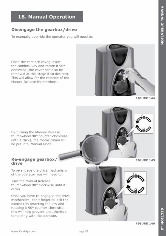
page 93www.CentSys.com
MA
NU
AL O
PE
RA
TIO
NS
EC
TIO
N 1
8
18. Manual Operation
Disengage the gearbox/driveTo manually override the operator you will need to:
FIGURE 144
FIGURE 145
FIGURE 146
Open the camlock cover, insert the camlock key and rotate it 90° clockwise (the cover can also be removed at this stage if so desired). This will allow for the rotation of the Manual Release thumbwheel.
By turning the Manual Release thumbwheel 90° counter-clockwise until it clicks, the motor pinion will be put into ‘Manual Mode’.
Re-engage gearbox/driveTo re-engage the drive mechanism of the operator you will need to:
Turn the Manual Release thumbwheel 90° clockwise until it clicks.
Once you have re-engaged the drive mechanism, don’t forget to lock the camlock by inserting the key and rotating it 90° counter-clockwise – this will help prevent unauthorised tampering with the operator.

page 94 www.CentSys.com
AD
DIT
ION
AL
FEA
TU
RE
SS
EC
TIO
N 1
9
19. Additional Features
Battery saverIn the event of a battery-low shutdown, only the motor will stop drawing current – the controller, infrared beams and any other peripheral devices will continue to flattenthebattery;however,atamuch slower rate.
An optional low cut-out switch (product code CP107) totally disconnects the battery and protects it from being fully discharged and potentially damaged.
Consult your gate automation specialist for further details.
Solar power supplyA solar panel can be used to charge the battery instead of the conventional charging circuit. A 20W panel will provide enough power for 20 daily operations of an average gate (less if 12V DC security lightsarefitted).
Youwillneedtofitadeep-cyclelow-maintenance battery (minimum 35Ah)inordertoprovidesufficientbackup capacity during days of poor weather.
These are typical values for Southern Africa. Contact your gate automation specialist for details on what solar panel to select in your area.
FIGURE 147
FIGURE 148
Refer to Figure 66 and 67 on pages 49 and 50 for instructions on how to connect a solar panel to your D2 Turbo/D2 Turbo Low-Voltage operator.
ThemainsfailbuzzercanbedisabledbyselectingtheSolarProfileoption(controllers manufactured after August 2014 only). Refer to ‘Customising the Features and Functions’ on page 65 for details.

page 95www.CentSys.com
BA
SIC
MA
INT
EN
AN
CE
SE
CT
ION
20
20. Basic Maintenance
Our operators are designed to be maintenance-free. However, there are some basic checks that should be carried out regularly (every six months). These checks will increase the long-term reliability of the system and prevent erratic operation of your gate.
FIGURE 149
FIGURE 150
Isolate mains supply to system before cleaning or working on the equipment
GeneralEven if the user has used a gate operator before, it does not mean that he knows how to SAFELY operate it. Make sure that the user fully understands the following safety requirementsbeforefinallyhandingoverthesite.
Show the user how to do the following:
• Keep the track clear of stones, dirt and obstructions
• Ensure that all rollers run freely• Put the operator into Manual
Mode and check that the gate runs freely on its rail and does not catch or foul against the walls or pillars
• Ensure that the gate wheels and guide-rollers are rotating freely and are not worn. In high-volume applications it will be necessary to replace these components regularly
• Ensure that the rack is properly secured to the gate and that it does not press down onto the operator pinion at any point along its travel
• Keep shrubs and vegetation clear of the motor and rack
• Check that the key still operates the camlock - spray with lubrication if necessary
• Keep the inside of the motor housing clean
• Theoperatorsarefittedwithhigh-quality,maintenance-freeleadacidbatterieswhichshould provide up to three years of normal service life.
• Check for corrosion of the battery terminals• Clean and apply copper-based grease as necessary
page 96 www.CentSys.com
SE
RV
ICIN
G T
HE
OP
ER
AT
OR
SE
CT
ION
21
21. Servicing the Operator
Referallservicingtoqualifiedservicepersonnel.Consultyourlocaldealerforassistance.
Your D2 Turbo sliding gate operator requires no special care other than that described in the Maintenance section. If you are having a problem with your D2 Turbo, please contact your installer or local dealer.
page 97www.CentSys.com
24
MO
NT
H C
AR
RY
-IN P
RO
DU
CT
WA
RR
AN
TY
SE
CT
ION
22
You can register your product(s) online at www.CentSys.co.za, which will assist you in keeping a record of your date of purchase or installation, serial numbers, etc.
All of our products are manufactured with extreme care, thoroughly inspected and tested.
The goods supplied by us shall be subject to the provisions of sections 55 to 57 of the Consumer Protection Act (68/2008) except where the provisions of the warranty contained in our product documentation are more favourable to the purchaser. Subject to the warranty contained in our product documentation, if applicable, our products are warranted for a period of twenty-four months after delivery. However, it is expressly noted that batteries carry a six month warranty due to the nature of these products being such that they are subject to possible misuse. Please note that warranties will be honoured on a carry-in basis; in other words, the product in question must be taken in to one of our branches, or to the authorised reseller that the product was purchased from, for assessment and, if necessary, repair. For equipment not of our manufacture, the warranty as supplied by the original manufacturer will apply if such warranty is more favourable to the purchaser than the relevant provisions of the Consumer Protection Act (Act68/2008ofSouthAfrica),oranyotherapplicablelawassorequiredindifferentcountries in which the product was sold. Such warranty is valid only once full payment has been received for such goods.
Australian customers:
Our goods come with guarantees that cannot be excluded under the Australian Consumer Law. You are entitled to a replacement or refund for a major failure and compensation for any other reasonably foreseeable loss or damage. You are also entitled to have the goods repaired or replaced if the goods fail to be of acceptable quality and the failure does not amount to a major failure
Any warranty may be voidable on any equipment which:
1. Has not been installed in accordance with the installation instructions provided.2. Has been subject to misuse or which has been used for any purpose other than that
designed for by the manufacturers.3. Has damage caused as a result of handling during transit, atmospheric conditions
(including lightning), corrosion of metal parts, insect infestation, power surges or other forces outside of the control of the manufacturer.
4. Has been repaired by any workshop and / or person NOT previously authorised by the manufacturer.
5. Has been repaired with components not previously tested, passed or authorised by Centurion Systems (Pty) Ltd, South Africa or one of its subsidiary companies.
Any warranty may be voidable on any equipment which:
1. There has been a failure to install the product in accordance with the installation instructions provided by the manufacturer, or
2. A failure to abide by the safety instructions provided by the manufacturer, or
22. 24 Month Carry-in Product Warranty
page 98 www.CentSys.com
24
MO
NT
H C
AR
RY
-IN
PR
OD
UC
T W
AR
RA
NT
YS
EC
TIO
N 2
2
3. There is no breach of a legal duty of care owed to you by us or by any of our employees or agents.
4. Such loss or damage is not a reasonably foreseeable result of any such breach, and any increase in loss or damage resulting from breach by you of any term of this contract.

page 99www.CentSys.com
INS
TA
LLAT
ION
HA
ND
OV
ER
SE
CT
ION
23
23. Installation Handover
Once the installation has been successfully completed and tested, it is important for the installer to explain the operation and safety requirements of the system.
Never assume the user knows how to safely operate an automated gate!
Even if the user has used a gate operator before, it does not mean he knows how to SAFELY operate it. Make sure that the user fully understands the following safety requirementsbeforefinallyhandingoverthesite.
1. The following needs to be understood by the user:• How to operate the Manual Release thumbwheel mechanism.
(Show them how by demonstration)• How the obstruction detection and all other safety features work.
(Show them how by demonstration)• Allthefeaturesandbenefitsoftheoperator,i.e.SafetyBeams,etc.• All the safety considerations associated with operating an automated gate. The user
should be able to pass this knowledge on to all other users of the automated system and must be made aware of this responsibility
• Do not activate the gate operator unless you can see it and can determine that its area of travel is clear of people, pets, or other obstructions
• NO ONE MAY CROSS THE PATH OF A MOVING GATE. Always keep people and objects away from the gate and its area of travel
• NEVER LET CHILDREN OPERATE OR PLAY WITH THE GATE CONTROLS, and do not allow children or pets near the gate area
• Becarefulwithmovingpartsandavoidcloseproximitytoareaswherefingersorhands could be pinched
• Secure all easily-accessed gate operator controls in order to prevent unauthorised use of the gate
• Keep the automated gate system properly maintained, and ensure that all working areasarefreeofdebrisandotherobjectsthatcouldaffectthegateoperationandsafety
• On a monthly basis, check the obstruction detection system and safety devices for correct operation
• Allrepairandserviceworktothisproductmustbedonebyasuitablyqualified person
• This product was designed and built strictly for the use indicated in this documentation. Any other use, not expressly indicated here, could compromise the good condition/operation of the product and/or be a source of danger!

page 100 www.CentSys.com
INS
TA
LLA
TIO
N H
AN
DO
VE
RS
EC
TIO
N 2
3
Neither Centurion Systems (Pty) Ltd, nor any of its subsidiaries, accepts any liability caused by improper use of the product, or for use other than that for which the automated system was designed.
Ensure that the customer is in possession of the User Guide and that you have completed the installation details in the back of the User Guide.
Once the installation has been successfully completed and tested, it is important for the installer to explain the operation and safety requirements of the system.
page 101www.CentSys.com
NO
TE
SNotes

page 102 www.CentSys.com
NotesNO
TE
S

page 103www.CentSys.com
NO
TE
SNotes

Call Centurion Systems (Pty) Ltd . South AfricaHead Office: +27 11 699 2400
Call Technical Support: +27 11 699 2481from 07h00 to 18h00 (UTC+2)
Connect with us on:
facebook.com/CenturionSystems
YouTube.com/CenturionSystems
@askCenturion
Subscribe to the newsletter: www.CentSys.com/Subscribe
www.CentSys.com
Doc number: 0.07.D.0038_21042015 ENGLISH