d1u86p-w-1600-12-hbxdc series | datasheet | murata power
TRANSCRIPT

D1U86P-W-1600-12-HBxDC.A03 Page 1 of 7
D1U86P-W-1600-12-HBxDC Series 86mm 1U Front End AC-DC Power Supply
www.murata-ps.com/support
www.murata-ps.com/en/3d/acdc.html www.murata-ps.com/en/3d/acdc.html www.murata-ps.com/en/3d/acdc.html www.murata-ps.com/en/3d/acdc.html www.murata-ps.com/en/3d/acdc.html www.murata-ps.com/en/3d/acdc.html
NB: D1U86P-W-1600-12-HB3DC Model Shown
PRODUCT OVERVIEW The D1U86P-W-1600-12-HBxDC products are high efficiency 1600 watt, power factor corrected front end supplies with a 12V main output and a 12V (30W) standby. They have current sharing and up to 8 supplies may be operated in parallel. The supplies may be hot plugged, they recover from over-temperature faults, and have logic and PMBus™ monitoring and control. Their low profile 1U package and >38.6W/cubic inch power density make them ideal for delivering reliable, efficient power to servers, workstations, storage systems and other 12V distributed power systems.
FEATURES
1600W output power
94% minimum efficiency at 50% load
12V main output
12V standby output of 30W
1U height: 3.4" x 7.78" x 1.59"
38.6 Watts per cubic inch density
N+1 redundancy, including hot plugging (up to 8
in parallel)
Droop Current sharing both outputs
Overvoltage, overcurrent, overtemperature
protection
Internal cooling fan (variable speed)
PMBus™ / I²C interface monitoring and control
RoHS compliant
Two Year Warranty
Available now at: http://power.murata.com/en/3d/acdc.html
ORDERING GUIDE
Part Number Power Output; AC Line Main
Output Standby Output
Airflow Handle Colour (90-264V) (108-264V) (180-264V)
D1U86P-W-1600-12-HB4DC 1200W 1350W 1600W 12V 12V
Back to Front
Red
D1U86P-W-1600-12-HB3DC Front to
Back Blue
INPUT CHARACTERISTICS Parameter Conditions Min. Nom. Max. Units Input Voltage Operating Range 90 115/230 264 Vac Frequency 47 50/60 63 Hz Turn-on Voltage Ramp up 81 89 Vac Turn-off Voltage Ramp down 70.5 73 78 Maximum Input Current 1200W, 100Vac 14.1 Arms Inrush Current At 264Vac at 25°C cold start 35 Apk Power Factor At 230Vac, half load 0.98
Efficiency (230Vac) excluding fan load
20% load 90 % 50% load 94
100% load 91 OUTPUT VOLTAGE CHARACTERISTICS
Output Voltage
Parameter
Conditions
Min.
Typ.
Max.
Units
12V
Voltage Set Point 50% load 12.17 12.2 12.23 Vdc Line and Load Regulation 11.4 12.6 Droop 3.10 mV/A Ripple Voltage & Noise1 20MHz Bandwidth 120 mV p-p Output Current (230 Vac)2 0 133.4 A Output Current (120 Vac)2 0 112.5 A Output Current (100 Vac)2 0 100.0 A Load Capacitance 10,000 μF
12VSB Voltage Set Point 50% load 11.97 12.0 12.02 Vdc Ripple Voltage & Noise1 20MHz Bandwidth 120 mV p-p Output Current 0 2.5 A
1Ripple and noise measured with a parallel combination of a 1.0μF ceramic and 10μF tantalum capacitor on each of the power module outputs. A short coaxial cable connected directly to the input of a scope is required.
2To meet ripple and transient step load specifications a minimum load of 4A is required.
For full details go to www.murata-ps.com/rohs
Certificate and Test Report

D1U86P-W-1600-12-HBXDC.A03 Page 2 of 7
D1U86P-W-1600-12-HBxDC Series 86mm 1U Front End AC-DC Power Supply
www.murata-ps.com/support
OUTPUT CHARACTERISTICS Parameter Conditions Min. Typ. Max. Units Output Rise Monotonicity No voltage excursion Startup Time AC ramp up 1.5 3 s Transient Response
12V, 50% load step, 1.0Aμs di/dt 600 mV
12VSB, 50% load step,1.0Aμs di/dt 600 Current sharing accuracy (up to 8 in parallel)3 At 100% load ±5 % Hot Swap Transients All outputs remain in regulation 5 % Holdup Time At full load 12 ms
3 Load current of 100% applies to each power module max load connected in an N+1 configuration; therefore the total load will be “N” x 100%. The share accuracy of ±5% is a fixed percentage irrespective of total loading and number of units connected in parallel.
ENVIRONMENTAL CHARACTERISTICS Parameter Conditions Min. Typ. Max. Units Storage Temperature Range -40 85
°C Operating Temperature Range 0 55 Operating Humidity Noncondensing 5 90
% Storage Humidity 5 95 Altitude (without derating at 45°C) 3000 m Shock 30G non-operating Vibration 10-500Hz, 0.5G (non-operational) MTBF Per Telcordia SR-322 M1C1@40°C 559K hrs Acoustic 65 dBA/@1m Safety Approvals
CSA 60950-1-07+A1:2011 ANSI/UL 60950-1-2011, Second Edition IEC 60950-1:2005 (2nd Edition) + A1:2009 EN 60950-1:2006 +A11+A1+A2
Input Fuse Power Supply has internal 16A/250V fast blow fuse on the AC line input Weight 2.33/1.06 lbs/Kg
PROTECTION CHARACTERISTICS Output Voltage
Parameter
Conditions
Min.
Typ.
Max.
Units
Overtemperature (intake)
An OTP warning will be issued via the PMBus™ interface when the air inlet exceeds 65°C; however the power module shall not shut down until critical internal hotspot temperatures are exceeded.
65
°C
12V
Overvoltage Latching 13.2 14.4 V Overcurrent at 220Vac
Shutdown of the output followed by auto- recovery after one second. The output shall attempt three such auto-recovery attempts and then enter a permanent latched state. Recovery of the permanent latched state shall require cycling of the incoming AC source or toggling of the PSON# signal.
140
153
A Overcurrent at 120Vac
118
129
12VSB
Overvoltage Latching 13.2 14.4 V Overcurrent Auto-recovery 2.75 3 A
ISOLATION CHARACTERISTICS Parameter Conditions Min. Typ. Max. Units Insulation Safety Rating / Test Voltage
Input to Output - Reinforced 3000 Vrms
Input to Chassis - Basic 1500 Vrms
Isolation Output to Chassis 500 Vdc
Leakage Current 1.5mA at 264Vac, 50/60Hz
D1U86P-W-1600-12-HBXDC.A03 Page 3 of 7
D1U86P-W-1600-12-HBxDC Series 86mm 1U Front End AC-DC Power Supply
www.murata-ps.com/support
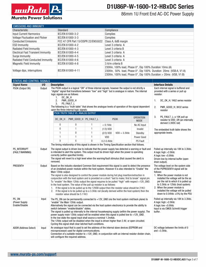
EMISSIONS AND IMMUNITY Characteristic Standard Compliance Input Current Harmonics IEC/EN 61000-3-2 Complies Voltage Fluctuation and Flicker IEC/EN 61000-3-3 Complies Conducted Emissions FCC 47 CFR Part 15/CISPR 22/EN55022 Class A, 6dB margin ESD Immunity IEC/EN 61000-4-2 Level 3 criteria A Radiated Field Immunity IEC/EN 61000-4-3 Level 3 criteria B Electrical Fast Transient Immunity IEC/EN 61000-4-4 Level 3 criteria A Surge Immunity IEC/EN 61000-4-5 Level 3 criteria A Radiated Field Conducted Immunity IEC/EN 61000-4-6 Level 3 criteria A Magnetic Field Immunity IEC/EN 61000-4-8 3 A/m criteria B Voltage dips, interruptions
IEC/EN 61000-4-11
230Vin, 100% load, Phase 0°, Dip 100% Duration 10ms (A) 230Vin, 50% load, Phase 0°, Dip 100% Duration 20ms (VSB:A, V1:A) 230Vin, 100% load, Phase 0°, Dip 100% Duration > 20ms (VSB, V1:B)
STATUS AND CONTROL SIGNALS Signal Name I/O Description Interface Details PSOK (Output OK) Output The PSOK output is a logical “OR” of three internal signals; however the output is not strictly a
“digital” signal that transitions between “low” and “high” but is analogue in nature. The internal logic signals are as follows:
1. DC_OK_H 2. PWR_GOOD_H 3. PS_FAULT_L
The following is a “truth table” that shows the analogue levels of operation of the signal dependent upon the three internal logic signals:
PSOK TRUTH TABLE VS. ANALOG OUTPUT
DC_OK_H PWR_GOOD_H PS_FAULT_L PSOK OPERATION MODE
0 0 1 < 0.1Vdc
VDD = 3.3Vdc
No AC Input 0 1 1 (1/3) VDD Invalid 1 0 1 (2/3) VDD Standby 1 1 1 VDD Power Good X X 0 0.2-0.4Vdc PS Fault
The timing relationship of this signal is shown in the Timing Specification section that follows.
Each internal signal is buffered and provided with a series or pull up resistor:
1. DC_OK_H; 1K62 series resistor
2. PWR_GOOD_H; 3K32 series
resistor
3. PS_FAULT_L; a 10K pull up resistor to VDD_OR (an internally derived 3.3VDC rail)
The embedded truth table shows the appropriate levels.
PS_INTERRUPT (FAULT/WARNING)
Output The signal output is driven low to indicate that the power supply has detected a warning or fault and is intended to alert the system. This output must be driven high when the power is operating correctly (within specified limits). The signal will revert to a high level when the warning/fault stimulus (that caused the alert) is removed.
Pulled up internally via 10K to 3.3Vdc. A logic high >2.0Vdc A logic low <0.8Vdc Driven low by internal buffer (open drain output).
PRESENT#
Output Based on the industry standard Common Slot requirement this signal is used to detect the presence of an (installed) power module within the host system. However it is also intended to “Enable” the Main 12Vdc output. The signal is also designed to control the power module during hot plug insertion/extraction in conjunction with the host system and is provided on a short “last to make; first to break” signal pin. To “enable” the Main 12Vdc output the signal requires to be pulled “high” with respect +12V_GND. In the host system. The value of the pull up resistor is as follows: 1. If the signal is to be pulled up to the 12VSB output then the resistor value should be 21KΩ 2. If the signal is to be pulled up to a 3.3Vdc rail (locally derived within the host system) then the
resistor value should be 5.11KΩ
The voltage level on the system side of the PSPRESENT# signal will be follows: 1. When the power module is not
installed the voltage will be the as per the rail to which it is pulled up to 3.3Vdc or 12Vdc (host system)
2. When the power module is installed the voltage will be pulled down to 0.54Vdc ±5%) by the PSU
PS_ON
(Power Supply Enable/Disable
Input The PS_ON can be permanently connected to +12V_GND (via the host system mid/back plane) to “enable” the Main 12Vdc output. Alternatively the signal can be connected via the host system electronics to provide the ability to switch between “enable/disable” states. The signal is pulled up internally to the internal housekeeping supply (within the power supply). The power supply main 12Vdc output will be enabled when this signal is pulled low to +12V_GND. In the low state the signal input shall source a nominal 1.2mAdc. The 12Vdc output will be disabled when the input is driven higher than 2.4V, or open circuited. Cycling this signal shall clear latched fault conditions.
Pulled up internally via 10K to 3.3Vdc. A logic high >2.0Vdc A logic low <0.8Vdc Input is via CMOS Schmitt trigger buffer.
ADDR (Address Select) Input An analogue input that is used to set the address of the internal slave devices (EEPROM and microprocessor) used for digital communications. Connection of a suitable resistor to +12V_GND, in conjunction with an internal resistor divider chain, will configure the required address.
DC voltage between the limits of 0 and +3.3Vdc.

D1U86P-W-1600-12-HBXDC.A03 Page 4 of 7
D1U86P-W-1600-12-HBxDC Series 86mm 1U Front End AC-DC Power Supply
www.murata-ps.com/support
STATUS AND CONTROL SIGNALS (CONTINUED) Signal Name I/O Description Interface Details SCL (Serial Clock) Both A serial clock line compatible with PMBusTM Power Systems Management Protocol Part 1 – General
Requirements Rev 1.1. No additional internal capacitance is added that would affect the speed of the bus. The signal is provided with a series isolator device to disconnect the internal power supply bus in the event that the power module is unpowered,
VIL is 0.8V maximum VOL is 0.4V maximum when sinking 3mA VIH is 2.1V minimum
SDA (Serial Data) Both A serial data line compatible with PMBusTM Power Systems Management Protocol Part 1 – General Requirements Rev 1.1. The signal is provided with a series isolator device to disconnect the internal power supply bus in the event that the power module is unpowered,
VIL is 0.8V maximum VOL is 0.4V maximum when sinking 3mA VIH is 2.1V minimum
IMONITOR Analogue Voltage
An analogue DC output voltage signal directly proportional to load current and can be used as an indication of the power supply’s load current. This signal of multiple connected units should not be tied together.
Analogue output voltage: 60.15mV/Amp
STATUS INDICATOR CONDITIONS LED State Mode Operating Condition 1. Off AC Turn-off The incoming AC source is below the minimum power module turn-on specification 2. Green – blinking 1Hz Standby The power module VStandby output is operating within normal parameters and main output is disabled 3. Green – solid Power-good The power module active; VStandby & Main outputs are operating within normal parameters and delivering
4. Yellow – blinking 1Hz Warning A warning condition within the power supply has been detected 5. Yellow – solid Fault A fault condition within the power supply has been detected.
TIMING DIAGRAM
AC Input
Vout_STBY
Vout_main
PSOK
PSON
TAC_OK_On
Tsb_On
Tsb_Vout
TPWR_GOOD_On
TAC_OK_OFF
TPWR_GOOD_Hold-up
TVout_Hold-up
Tsb_Hold-up
TPWR_GOOD_OFF
TPSON_On_Delay2.2 V
3.3 V*Note
*NOTE: The PSOK levels after the loss of the incoming AC source may be either 1.1V or 2.2V depending on the relative timing of the TACPOK_OFF and TPWRP_GOOD_HOLD-Up
TIMING SPECIFICATIONS Parameter Description Min Max Unit Tsb_On Delay from AC being applied to standby output being within regulation 0 3000 ms Tsb_Vout Delay from standby output to main output voltage being within regulation 50 500 ms TPWR_GOOD_On Delay from output voltages within regulation limits to PWR_GOOD assertion 20 500 ms TAC_OK_OFF Delay from loss of AC to deassertion of AC_OK 20 60 ms TAC_OK_On Delay from AC being applied to assertion of AC_OK 1 3000 ms TPWR_GOOD_Hold-up Delay from loss of AC to deassertion of PWR_GOOD 7 30 ms TVout_Hold-up Delay from loss of AC to main output being out of regulation 12 20 ms Tsb_Hold-up Delay from loss of AC to standby output being out of regulation 20 2000 ms TPWR_GOOD_OFF Delay from deassertion of PWR_GOOD to output falling out of regulation 0 2 ms TPSON_On_Delay Delay from PSON assertion to output being within regulation 1 200 ms

D1U86P-W-1600-12-HBXDC.A03 Page 5 of 7
D1U86P-W-1600-12-HBxDC Series 86mm 1U Front End AC-DC Power Supply
www.murata-ps.com/support
OUTPUT CONNECTOR AND SIGNAL SPECIFICATION Pin# Function Pin Type Description 14-26, 39-51
+12V_GND/RTN Power Ground
Power and Standby Return
1-13, 52-64 +12V Power 12V Output 37 +12VSB Power 12V Standby Output
38 PSINTERRUPT Output Active low; interrupt line for power supply fault & warning detection as per PMBus™ spec
36 PRESENT# Input Power Supply Present Signal (shortest pin)
35
PSOK
Analog output
Combination of three power supply output indicator signals: 1. AC input OK 2. Power Good 3. Power Supply Fault
34
IMONITOR
Analog I/O
main output current signal ypical analog voltage shall be 60.15mV/Amp of main output current.
33 PSON# Input Power Supply on/off control signal 32 SCL Input SMBus/PMBus Clock 31 SDA I/O SMBus/PMBus Data 30 +12V_GND/RTN Analog I/O Power Supply Signal Ground 29 N/A N/A Reserved; no User connection 28 N/A N/A Reserved; no User connection 27 ADDR Analog input PMBus Address
Power Supply Output Card Edge
PCB Top Side PCB Bottom Side
DERATING CURVES DERATING CURVES

D1U86P-W-1600-12-HBXDC.A03 Page 6 of 7
D1U86P-W-1600-12-HBxDC Series 86mm 1U Front End AC-DC Power Supply
www.murata-ps.com/support
WIRING DIAGRAM FOR OUTPUT
CURRENT SHARING NOTES Main Output: Current share is achieved using the droop method. Nominal output voltage (12.20V) is achieved at 50% load and output voltage varies at a rate of 3.10mv per amp increase/decrease. Startup of parallel power supplies is not internally synchronized. If more than 1600W combined power is needed, start-up synchronization must be provided by using a common PS_ON signal. To account for ±5% full load current sharing accuracy and the reduction in full load output voltage due to droop, available output power must be derated by 10% when units are operated in parallel. The Standby output can be tied together for redundancy however the total combined power must not exceed the Standby rail capability (30W) of a single supply. Internal MOSFET ORING devices are employed.
VSB Load
+12V Load
D1U86x
RTN
+12V
12VSB 12VSB
PSON# PSON#
1-13, 52-64
D1U86x
1-13, 52-64
14-26, 39-51 14-26, 39-51
37 37
33 33
+12V
RTN
FET, BJT, wire or switch (debounced)
to turn on +12V Main Output
FET, BJT, wire or switch (debounced)
to turn on +12V Main Output
RTN RTN14-26, 39-51 14-26, 39-51
PRESENT#
SYSTEM12V OR 3.3V
PRESENT#
SYSTEM12V OR 3.3V
36 36

D1U86P-W-1600-12-HBXDC.A03 Page 7 of 7
D1U86P-W-1600-12-HBxDC Series 86mm 1U Front End AC-DC Power Supply
www.murata-ps.com/support
MECHANICAL DIMENSIONS
1. AC input connector: IEC 320-C14 2. 86.4mm x 197.7mm x 40.5mm [3.4" x 7.78" x 1.59"] 3. This drawing is a graphical representation of the product and may not show all fine details. 4. Reference File: D1U86P-W-1600-12-HBxDC (TG1748-M1822)_Drawing for Product Datasheet_20160106.PDF
MATING CONNECTOR
Part Number Description FCI 10053363-200LF Right Angle FCI 10046971-001LF Vertical
OPTIONAL ACCESSORIES Description Part Number
12V D1U86P Output Connector Card D1U86P-12-CONC
APPLICATION NOTES Document Number Description Link
ACAN-50 D1U86P-12-CONC Interface Connector Card http://power.murata.com/datasheet?/data/apnotes/acan-50.pdf
ACAN-51 D1U86P PMBusTM Communication Protocol http://power.murata.com/datasheet?/data/apnotes/acan-51.pdf
Murata Power Solutions, Inc. 129 Flanders Rd. Westborough, Ma 01581, USA. ISO 9001 and 14001 REGISTERED
This product is subject to the following operating requirements and the Life and Safety Critical Application Sales Policy. Refer to: http://www.murata-ps.com/requirements/
Murata Power Solutions, Inc. (“Murata”) makes no representation that the use of its products in the circuits described herein, or the use of other technical information contained herein, will not infringe upon existing or future patent rights. The descriptions contained herein do not imply the granting of licenses to make, use, or sell equipment constructed in accordance therewith. Buyer represents and agrees that it has all the necessary expertise to create and implement safeguards that anticipate dangerous consequences of failures, monitor failures and their consequences, lessen the likelihood of failures that might cause harm, and take appropriate remedial actions. Buyer will fully indemnify Murata, its affiliated companies, and its representatives against any damages arising out of the use of any Murata products in safety-critical applications. Specifications are subject to change without notice. © 2018 Murata Power Solutions, Inc.